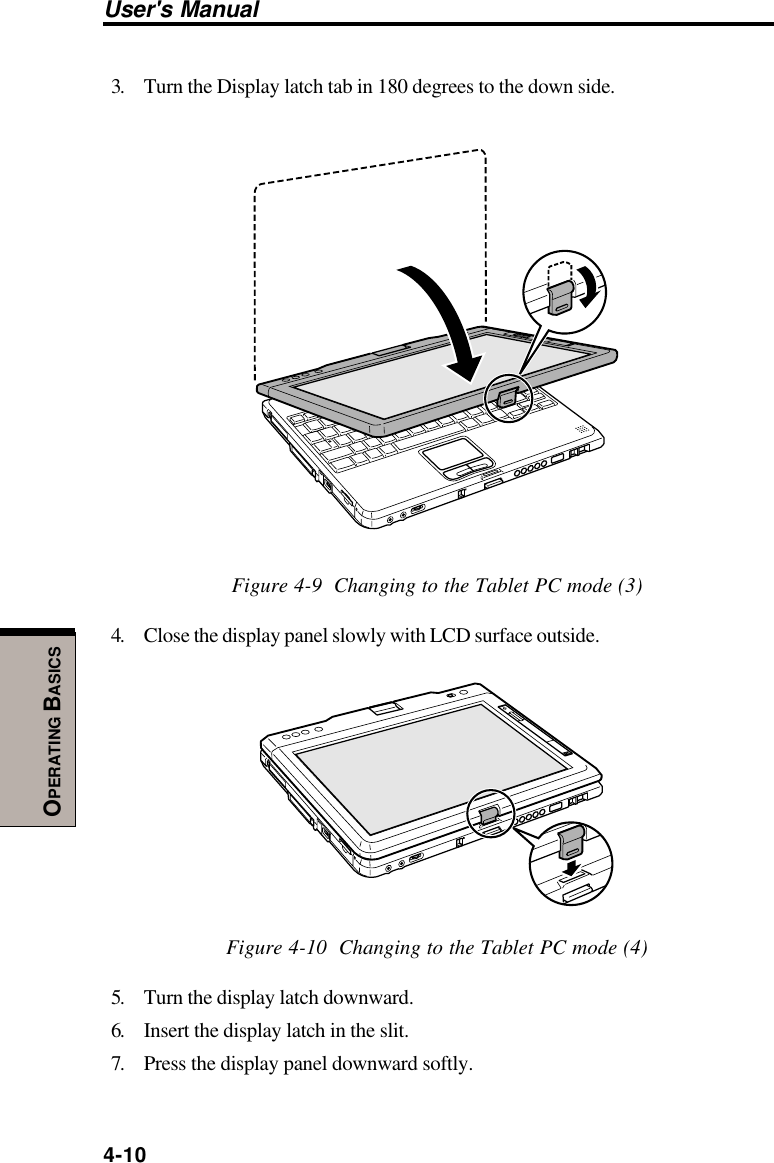
Dynabook UPP350BT Notebook PC with Bluetooth. Portégé 3500 User Manual cvr Guam
Toshiba Corporation Notebook PC with Bluetooth. Portégé 3500 cvr Guam
Dynabook >
Contents
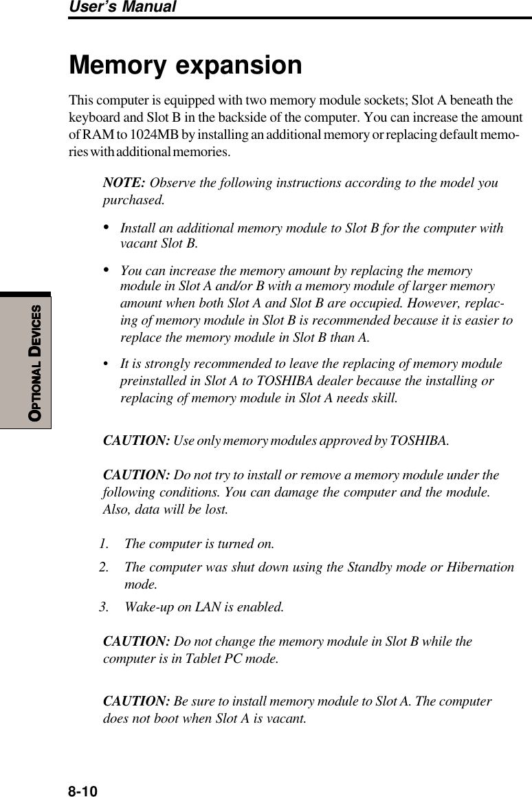
- 1. Notebook user manual
- 2. Bluetooth portion of user manual with RF exposure information
Notebook user manual

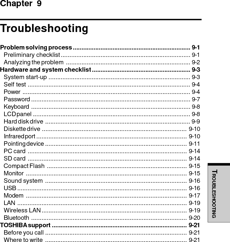
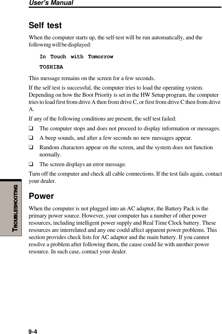
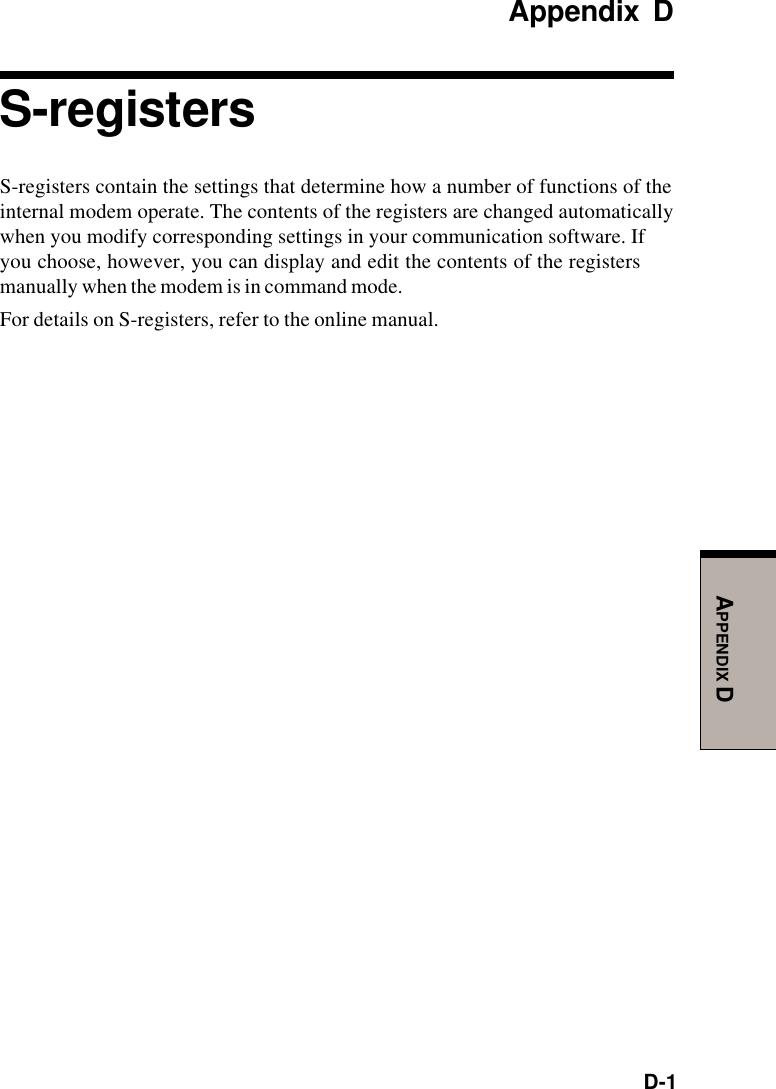
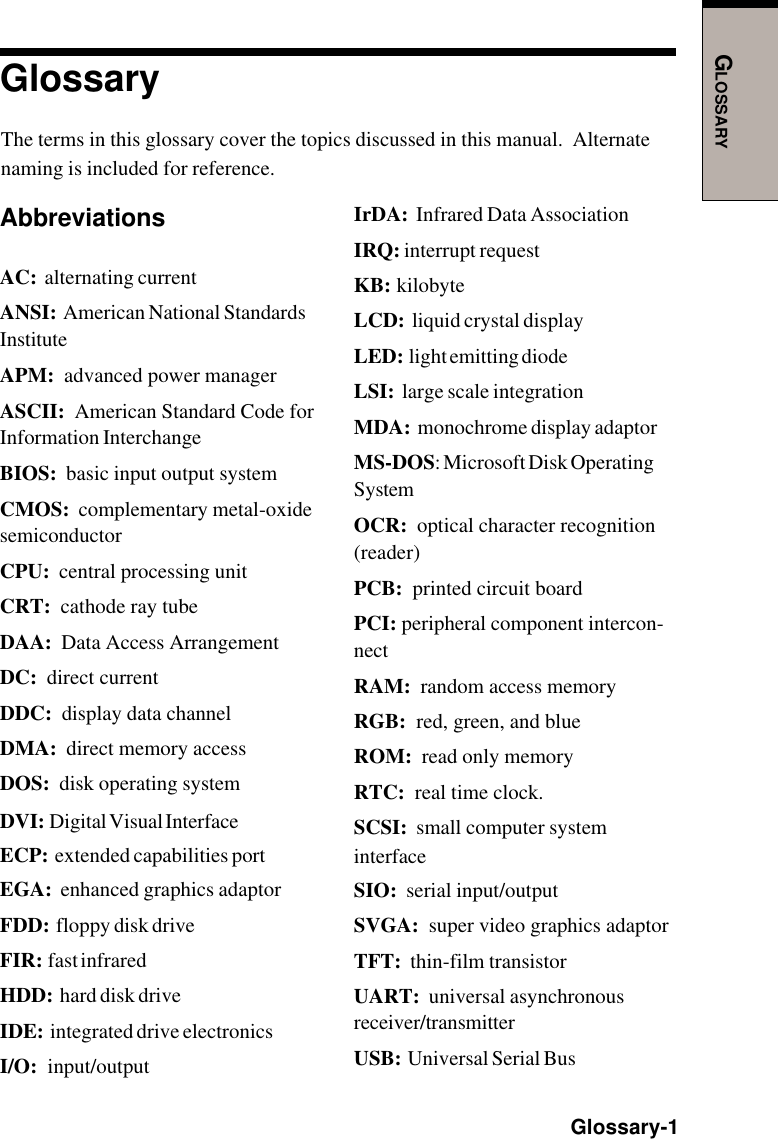
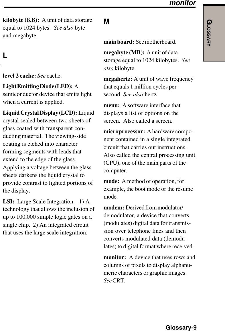
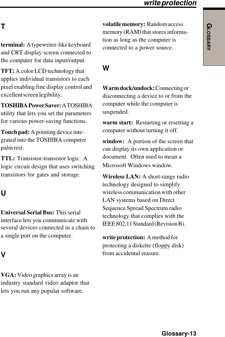
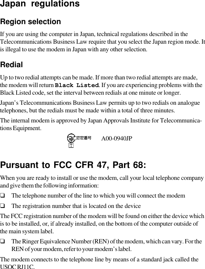
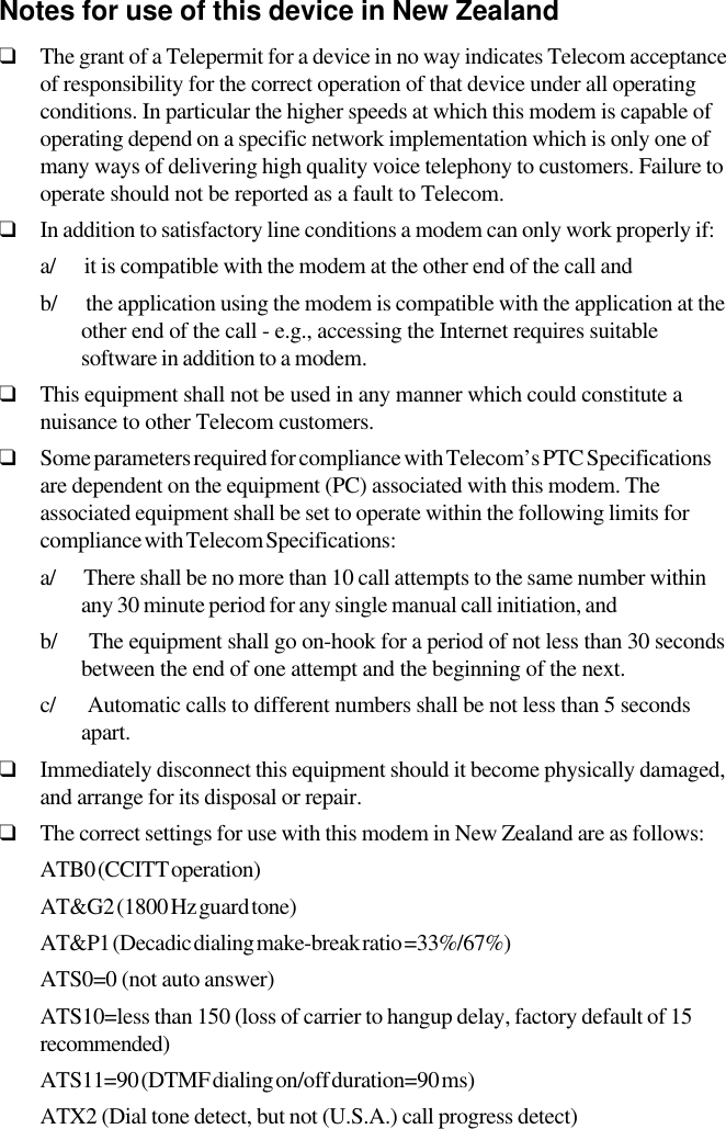
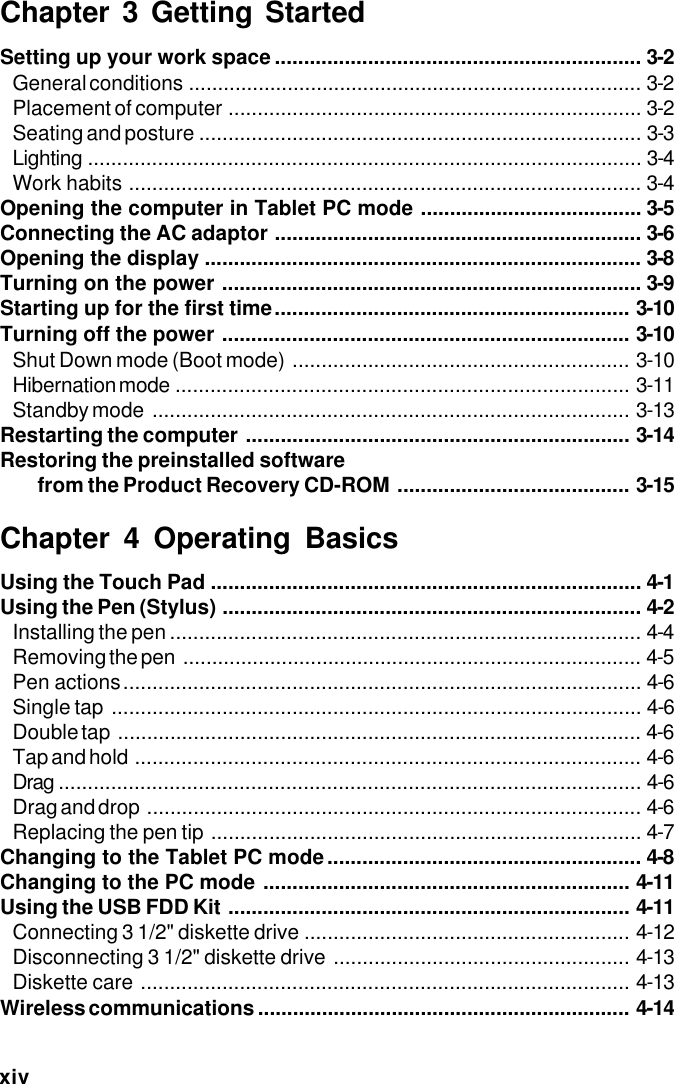
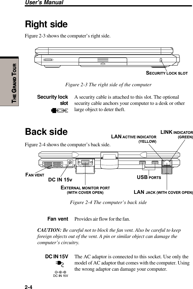
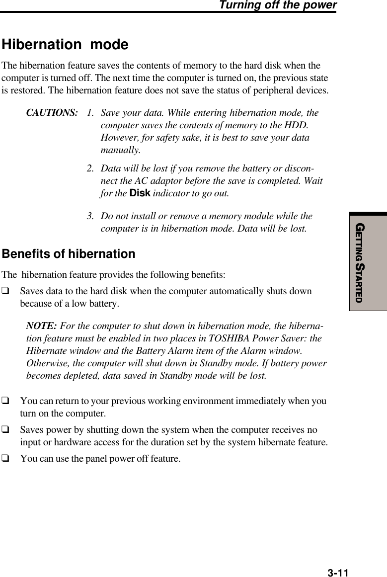
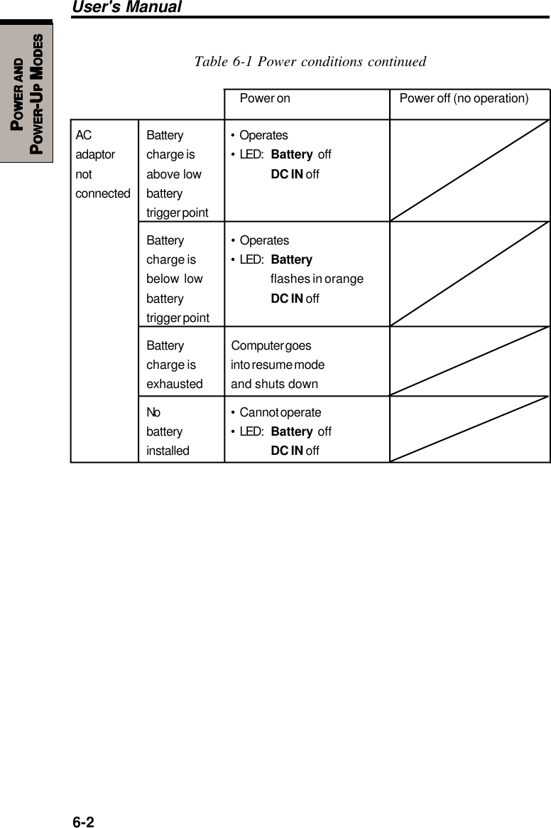
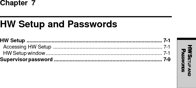
![Modem warning noticeConformity StatementThe equipment has been approved to [Commission Decision “CTR21”] for pan-European single terminal connection to the Public Switched Telephone Network(PSTN).However, due to differences between the individual PSTNs provided in differentcountries/regions the approval does not, of itself, give an unconditional assuranceof successful operation on every PSTN network termination point.In the event of problems, you should contact your equipment supplier in the firstinstance.Network Compatibility StatementThis product is designed to work with, and is compatible with the followingnetworks. It has been tested to and found to conform with the additional require-ments conditional in EG 201 121.Germany ATAAB AN005,AN006,AN007,AN009,AN010 andDE03,04,05,08,09,12,14,17Greece ATAAB AN005,AN006 and GR01,02,03,04Portugal ATAAB AN001,005,006,007,011 and P03,04,08,10Spain ATAAB AN005,007,012, and ES01Switzerland ATAAB AN002All other countries/regions ATAAB AN003,004Specific switch settings or software setup are required for each network, please referto the relevant sections of the user guide for more details.The hookflash (timed break register recall) function is subject to separate nationaltype approvals. It has not been tested for conformity to national type regulations,and no guarantee of successful operation of that specific function on specificnational networks can be given.](https://usermanual.wiki/Dynabook/UPP350BT.Notebook-user-manual/User-Guide-301519-Page-5.png)
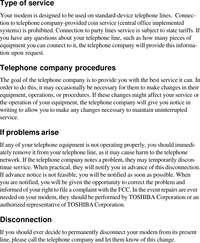
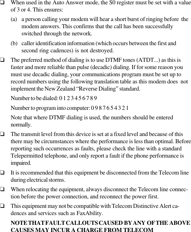
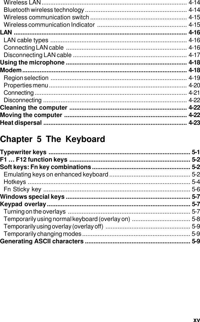
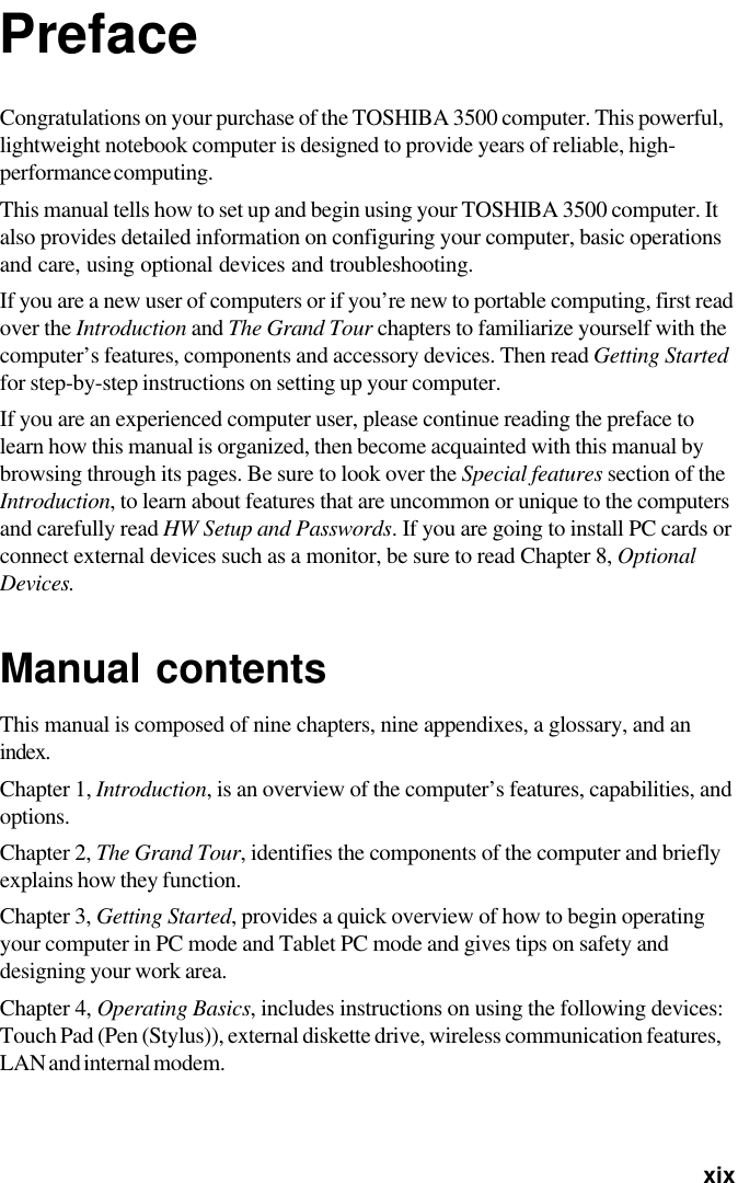

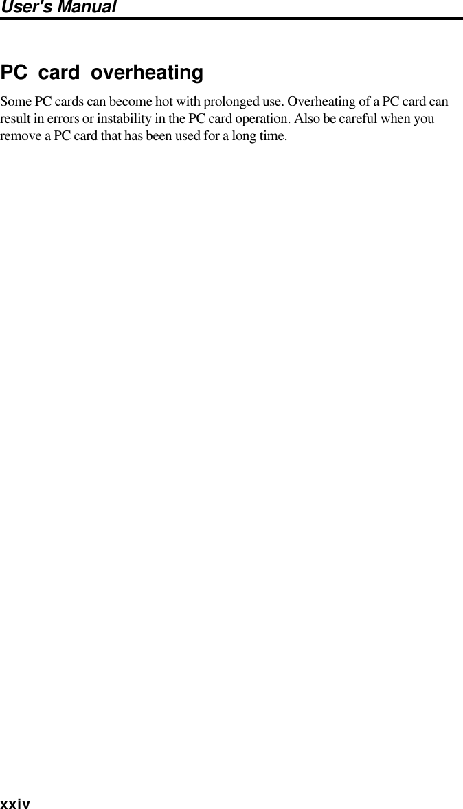
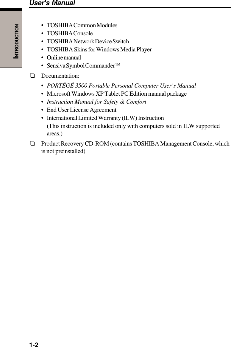
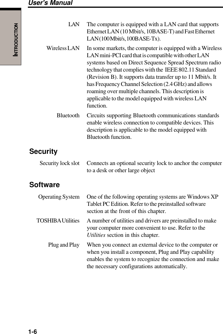
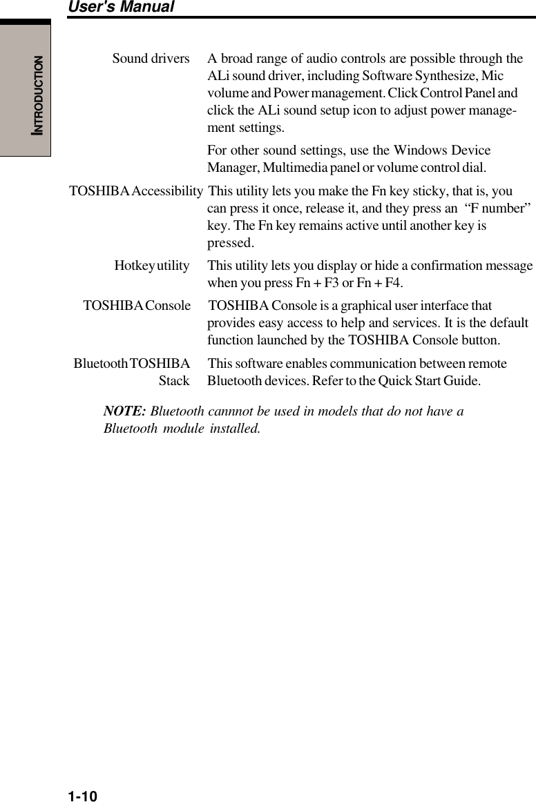

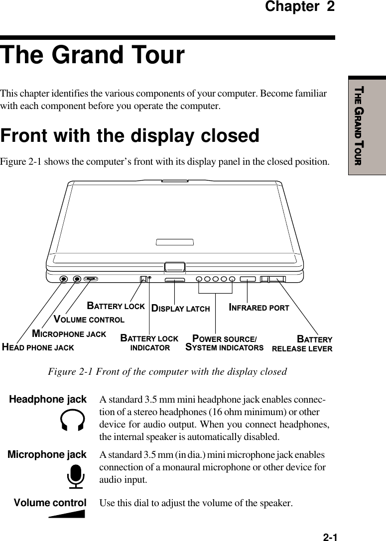
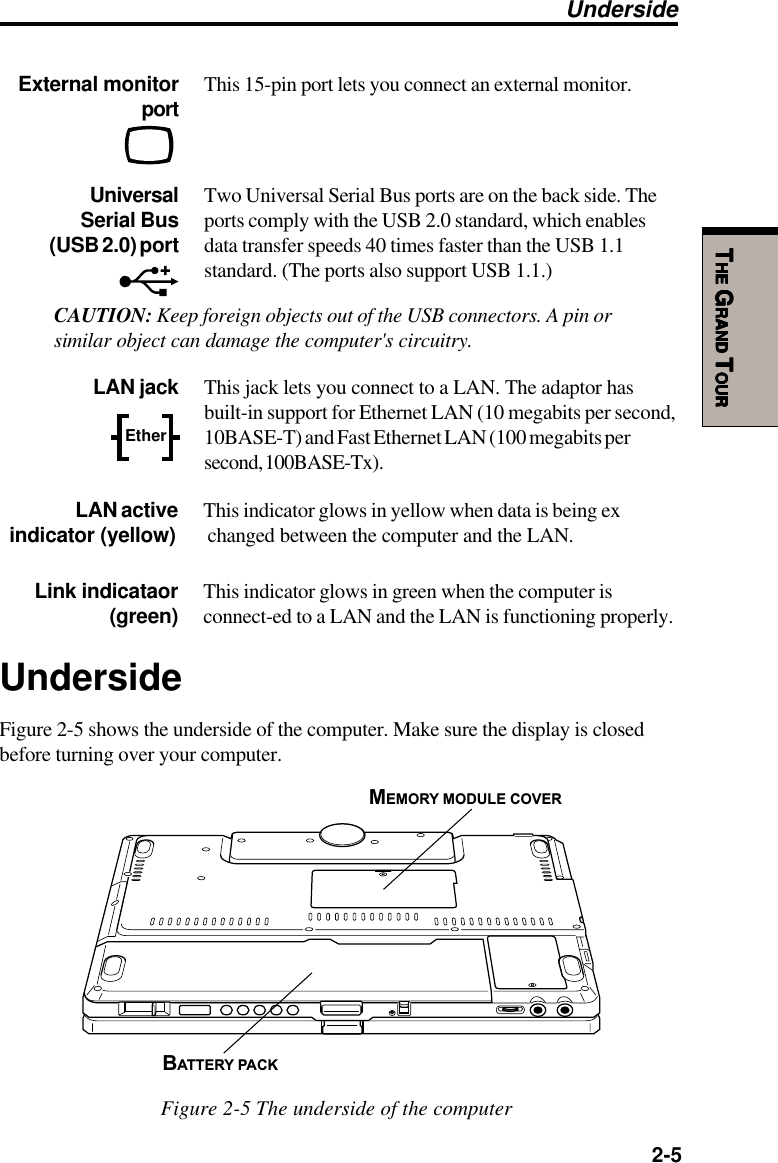

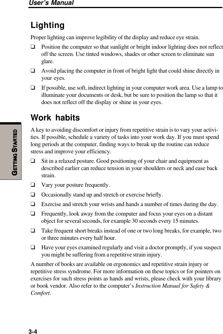
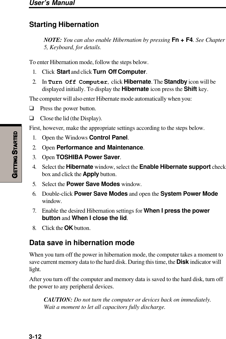

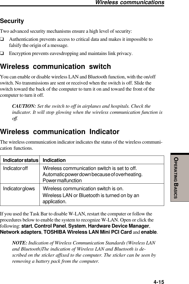
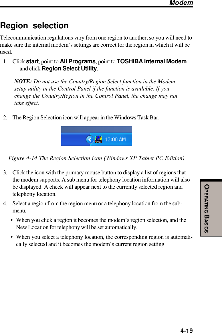
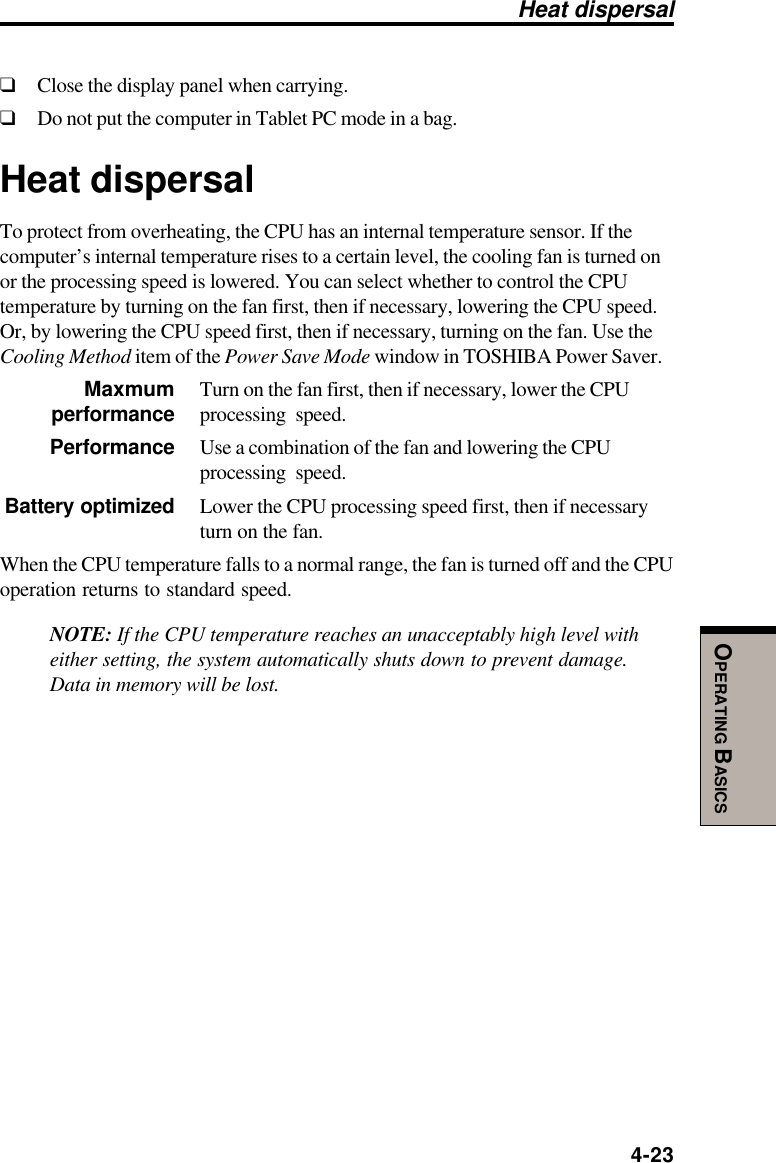
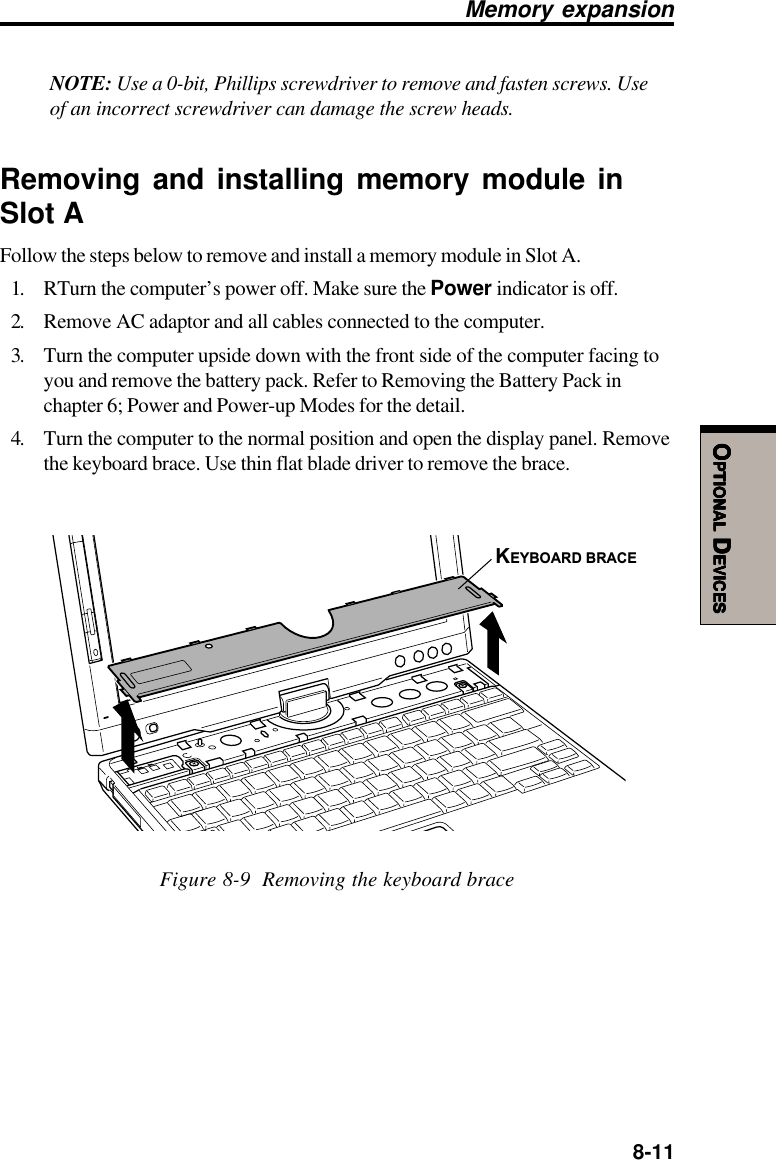
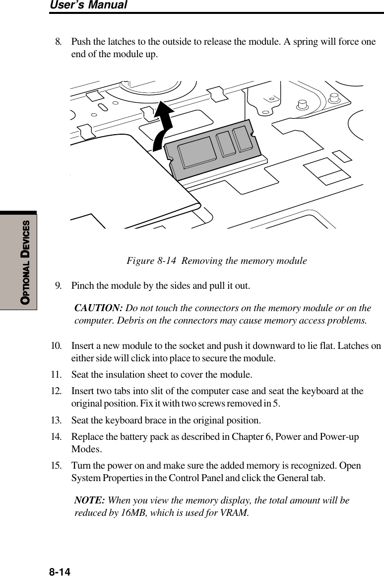
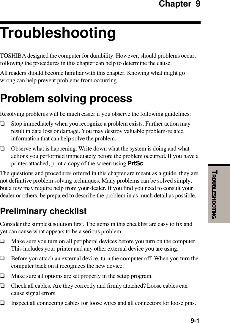
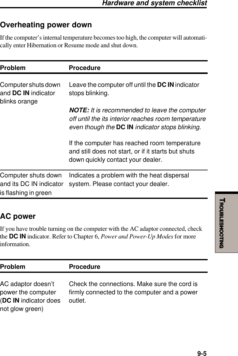
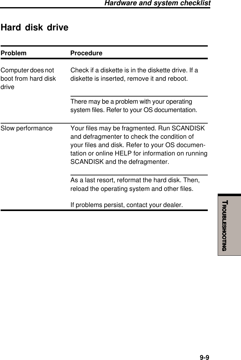
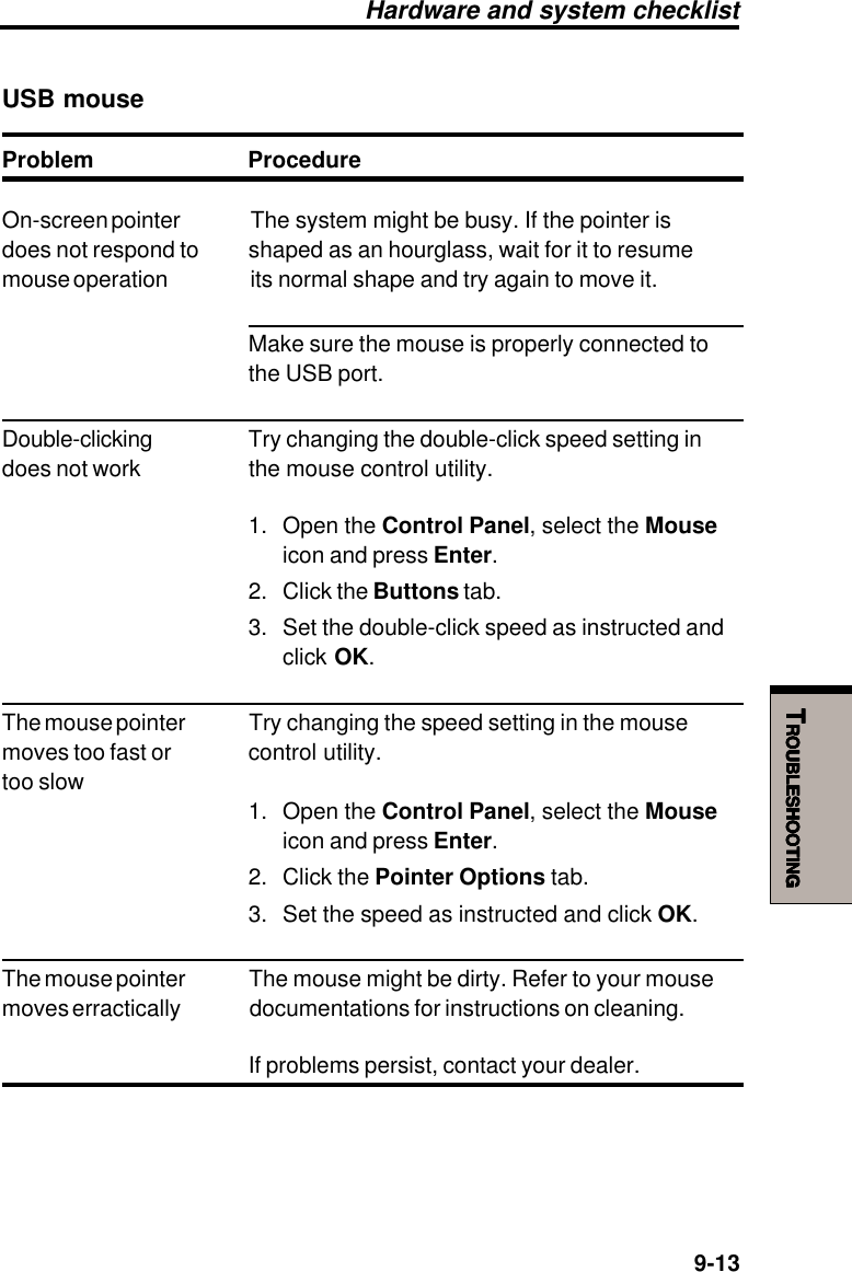
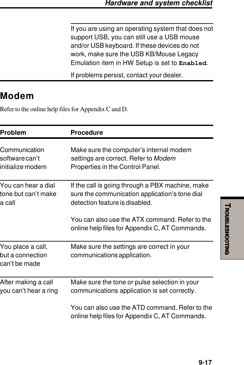
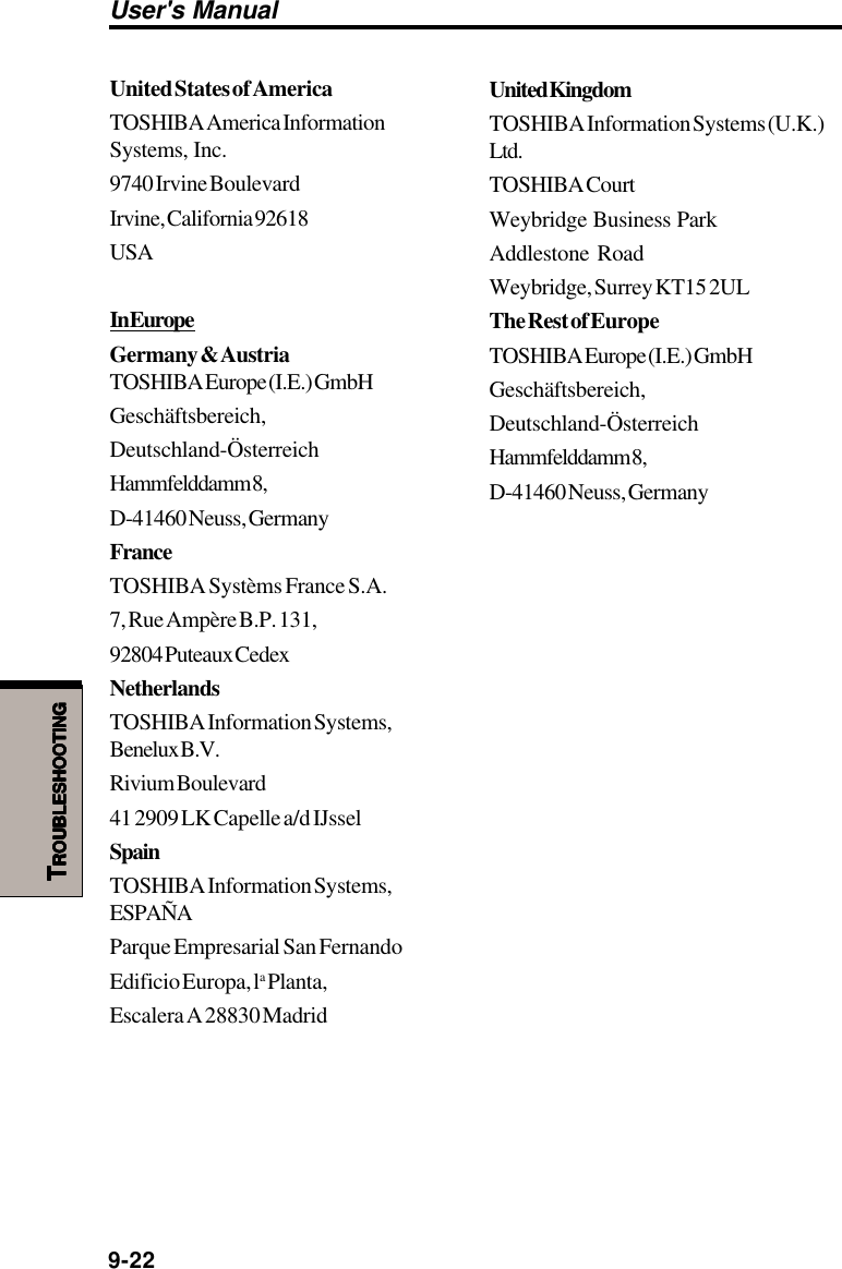
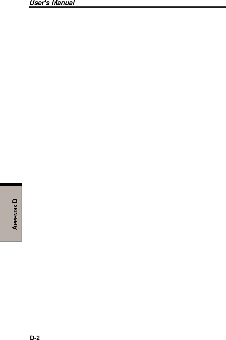
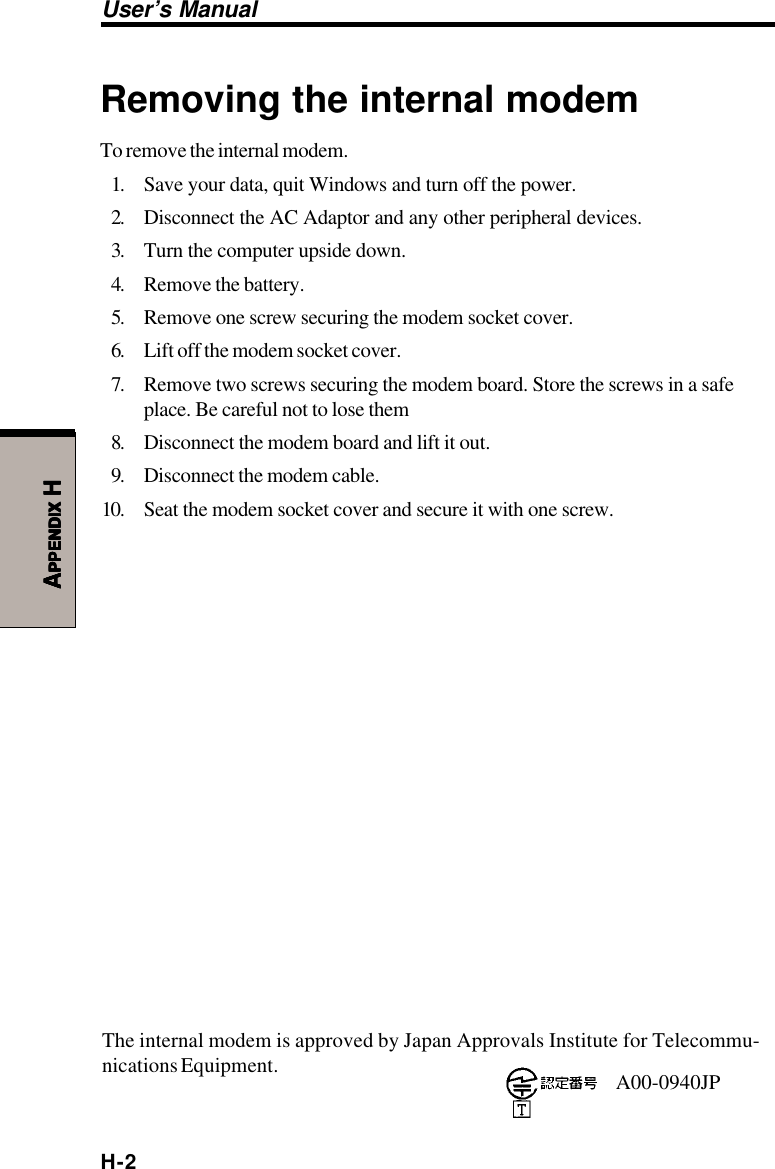
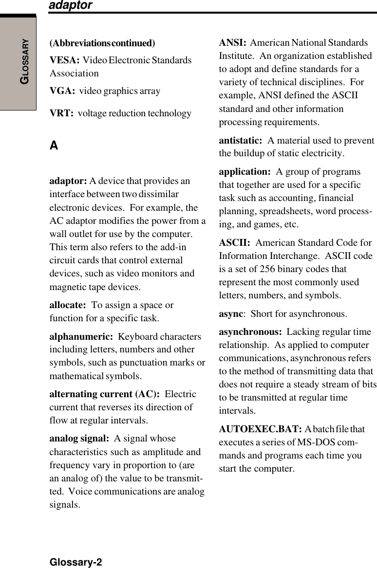
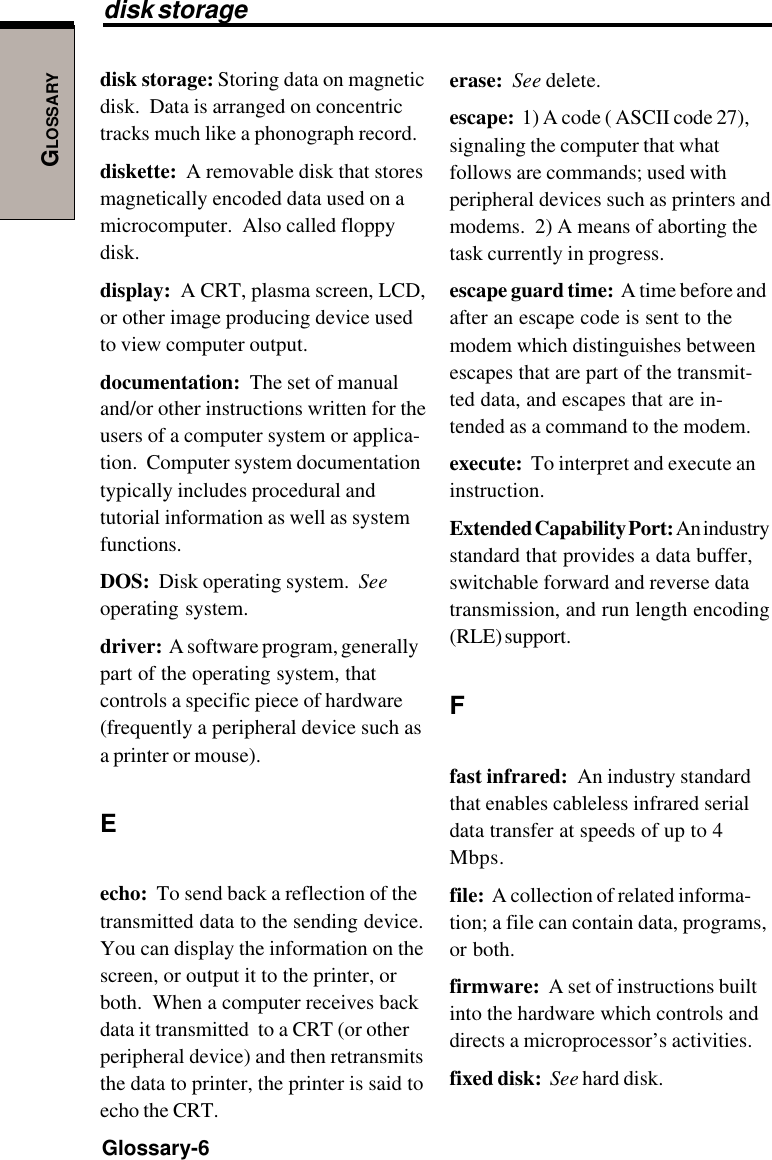
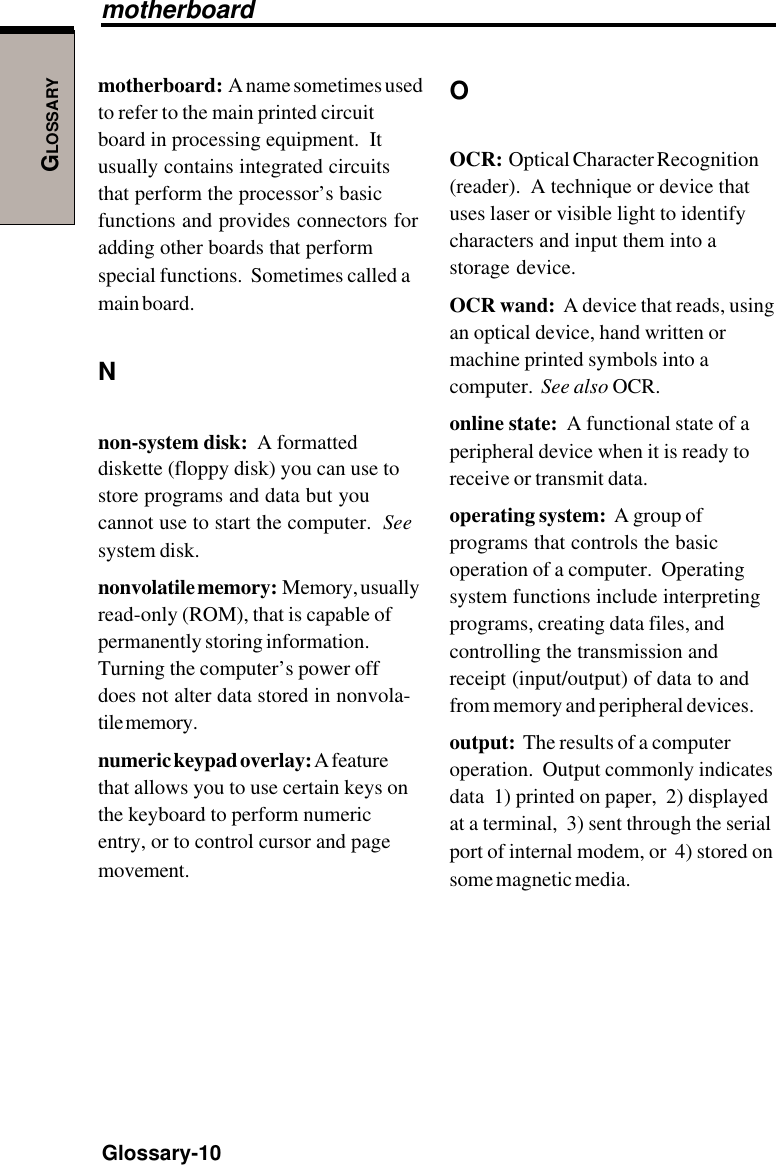
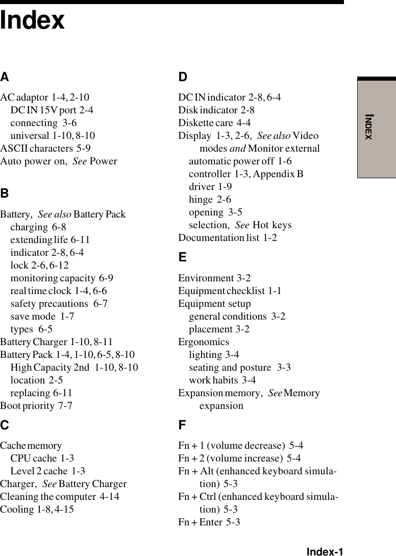
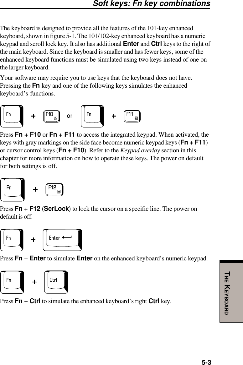
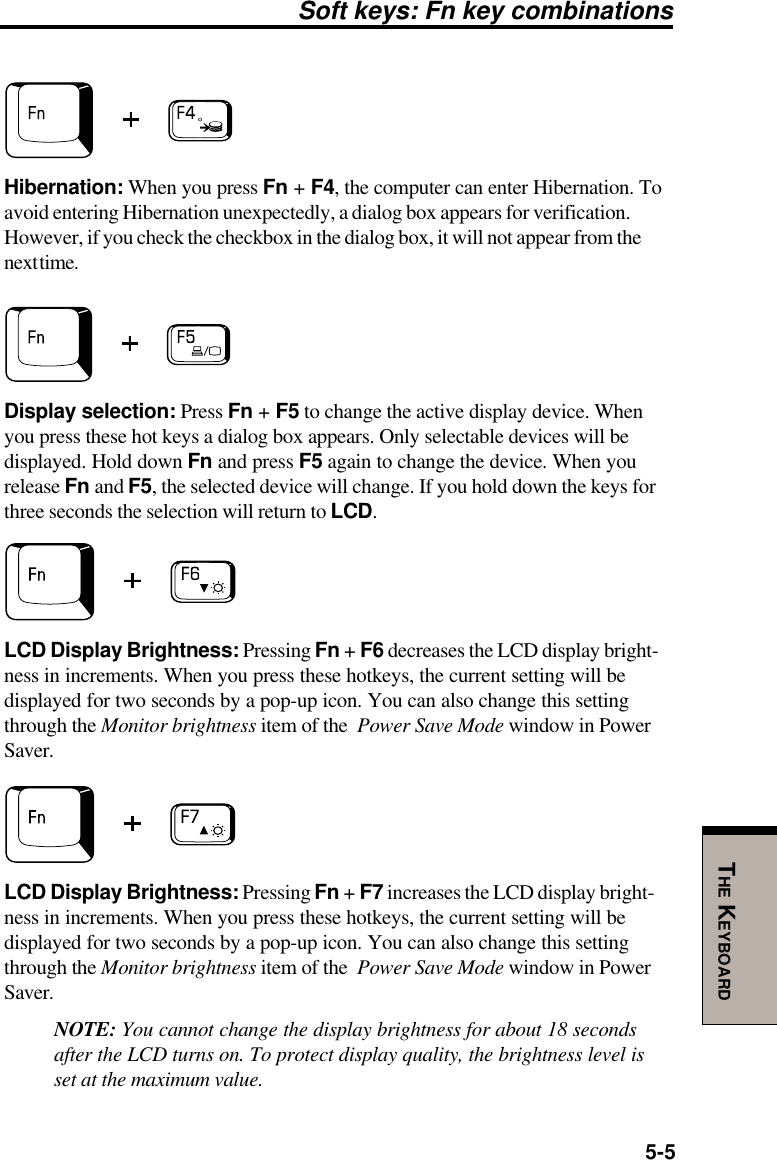
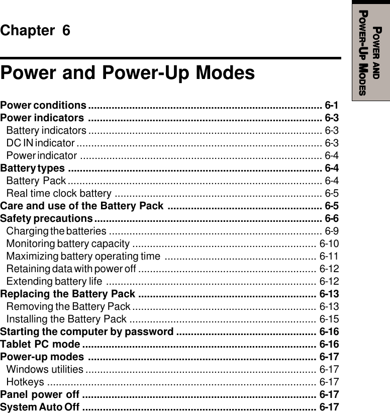
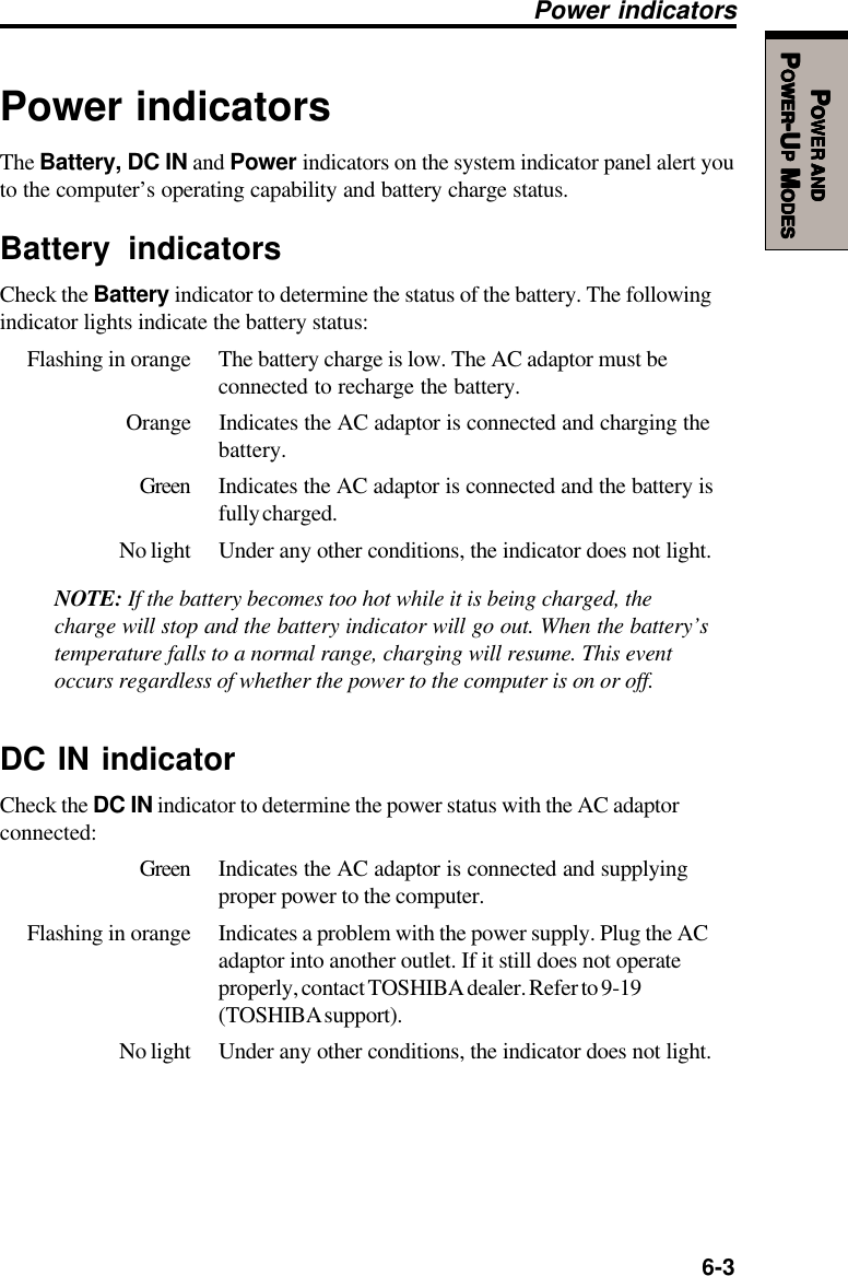
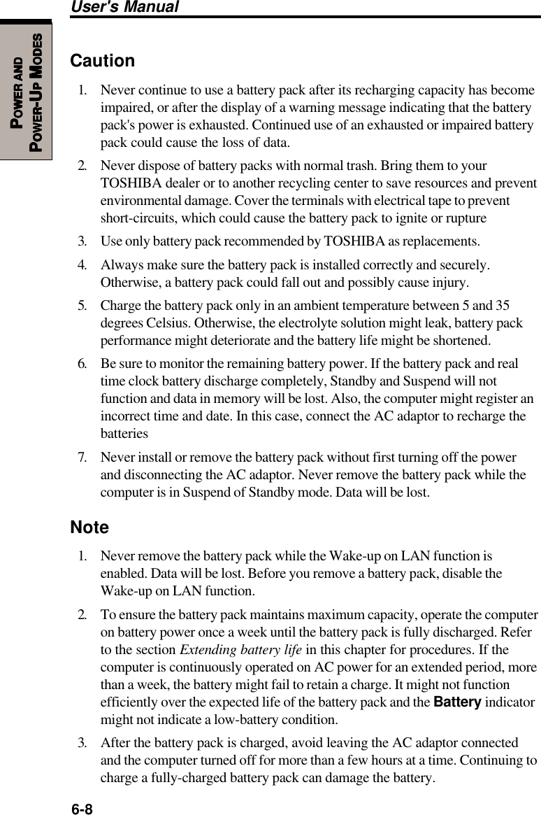
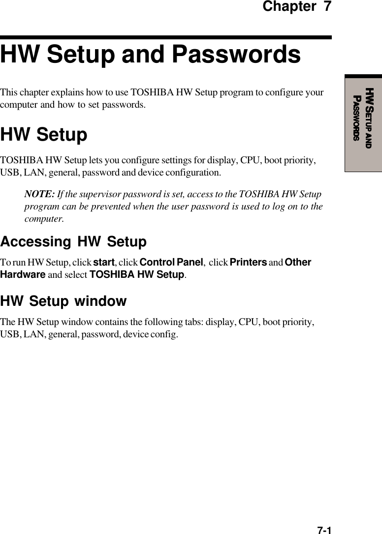
![User's Manual5-2THE KEYBOARDF1 … F12 function keysThe function keys, not to be confused with Fn, are the 12 keys at the top of yourkeyboard. These keys are dark gray, but function differently from the other darkgray keys.F1 through F12 are called function keys because they execute programmedfunctions when pressed. Used in combination with the Fn key, keys marked withicons execute specific functions on the computer. See the section, Soft keys: Fn keycombinations, in this chapter. The function executed by individual keys dependson the software you are using.Soft keys: Fn key combinationsThe Fn (function) is unique to TOSHIBA computers and is used in combinationwith other keys to form soft keys. Soft keys are key combinations that enable,disable or configure specific features.NOTE: Some software may disable or interfere with soft-key operations.Soft-key settings are not restored by the Resume feature.Emulating keys on enhanced keyboardEsc#3Home PgUpBk SpF1 F2 F3 F4 F5 F6 F7 F8 F9 F10 F11 F12 ! 12$4%568 (9 )0&7_+=PgDnEndShiftDelInsCapsLockShiftEnterQW RTYU I OP{[}]E~‘ASDFGHJ KL:;@?/> .< ,MNVCXZB\^*+-TabAltAltEnter 7Home8 9PgUp654 1End2 3PgDn 0InsNumLock .Del PrtScScroll lockPauseBreakCtrlCtrlSysReg/*.,,,Figure 5-1 A 101-key enhanced keyboard layout](https://usermanual.wiki/Dynabook/UPP350BT.Notebook-user-manual/User-Guide-301519-Page-100.png)

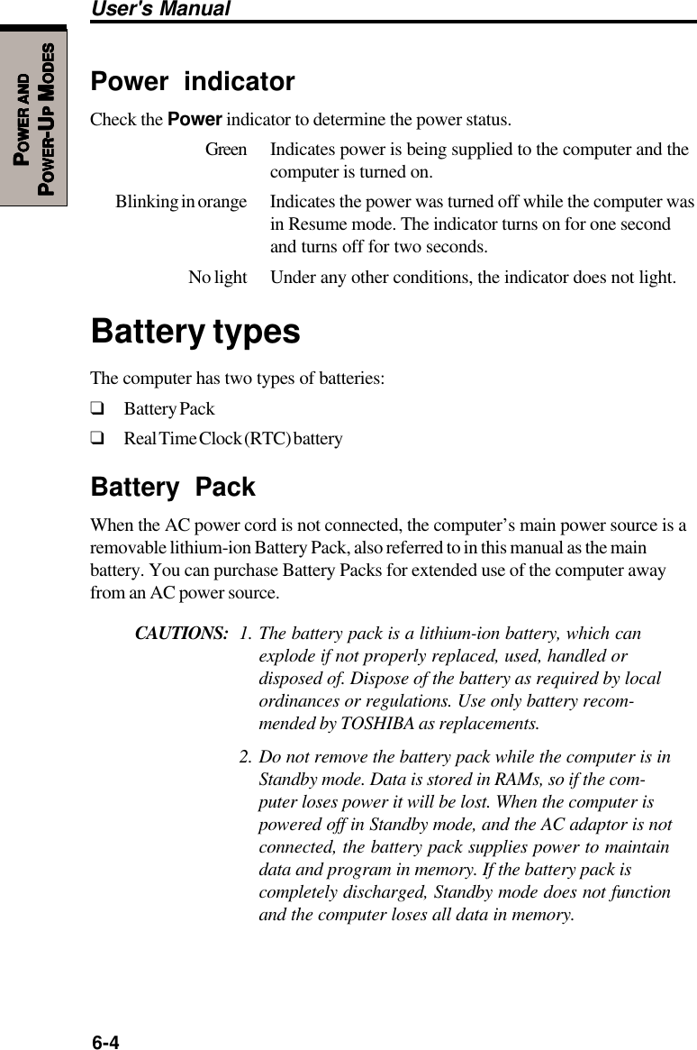
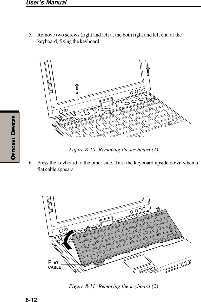
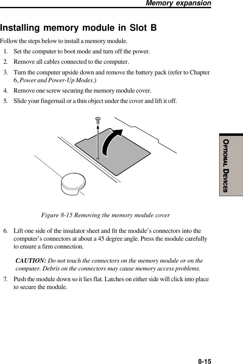
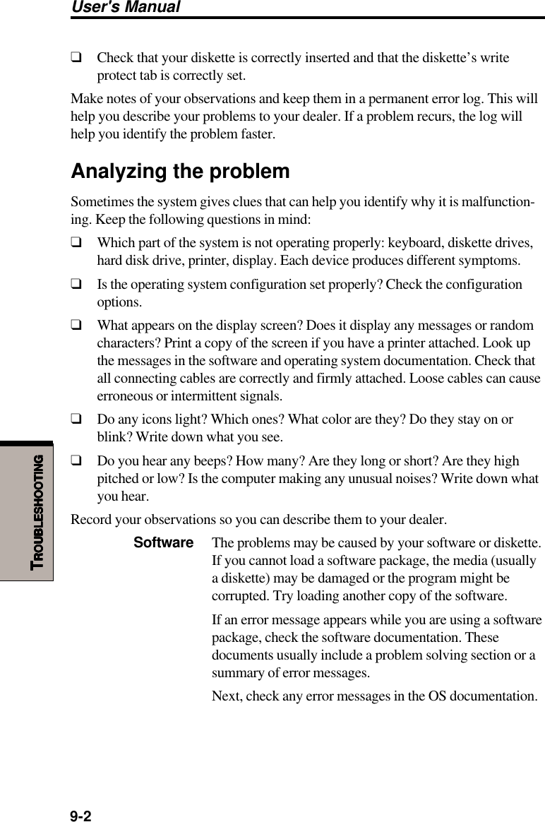
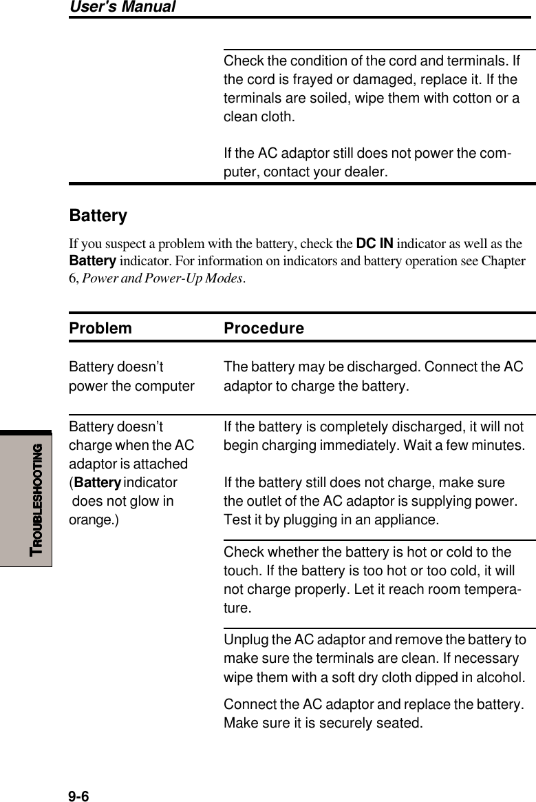
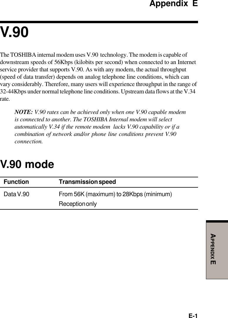
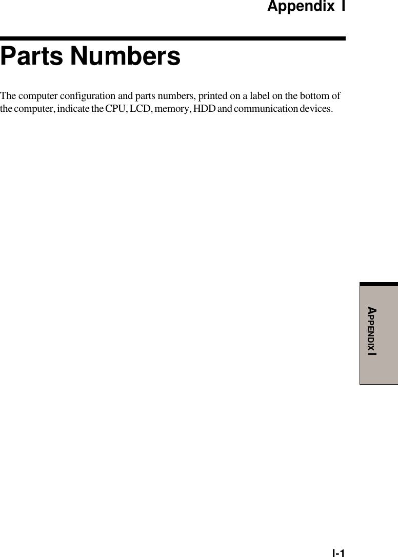
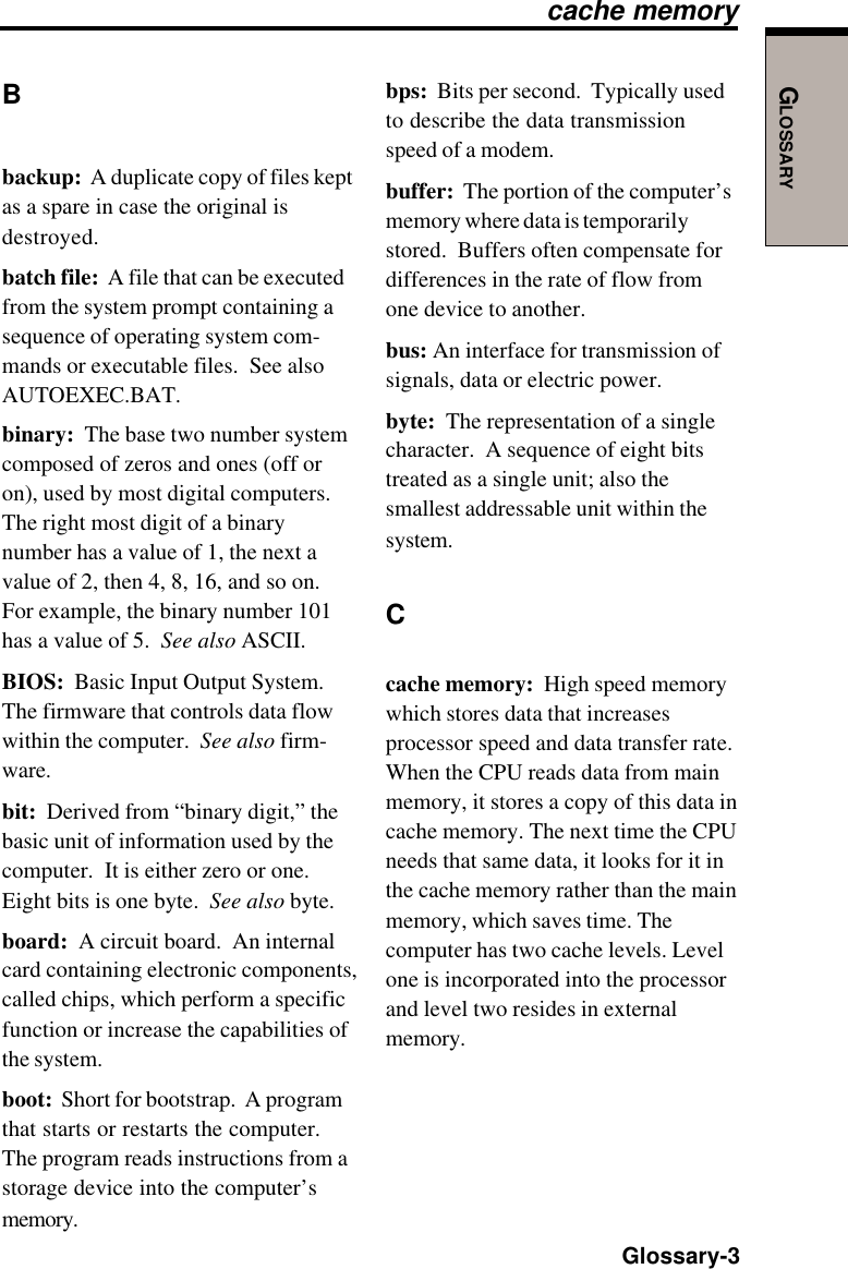
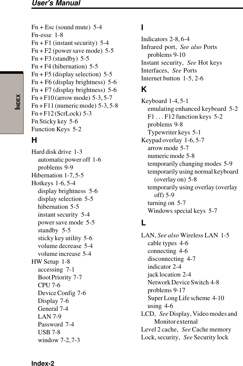
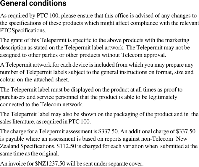
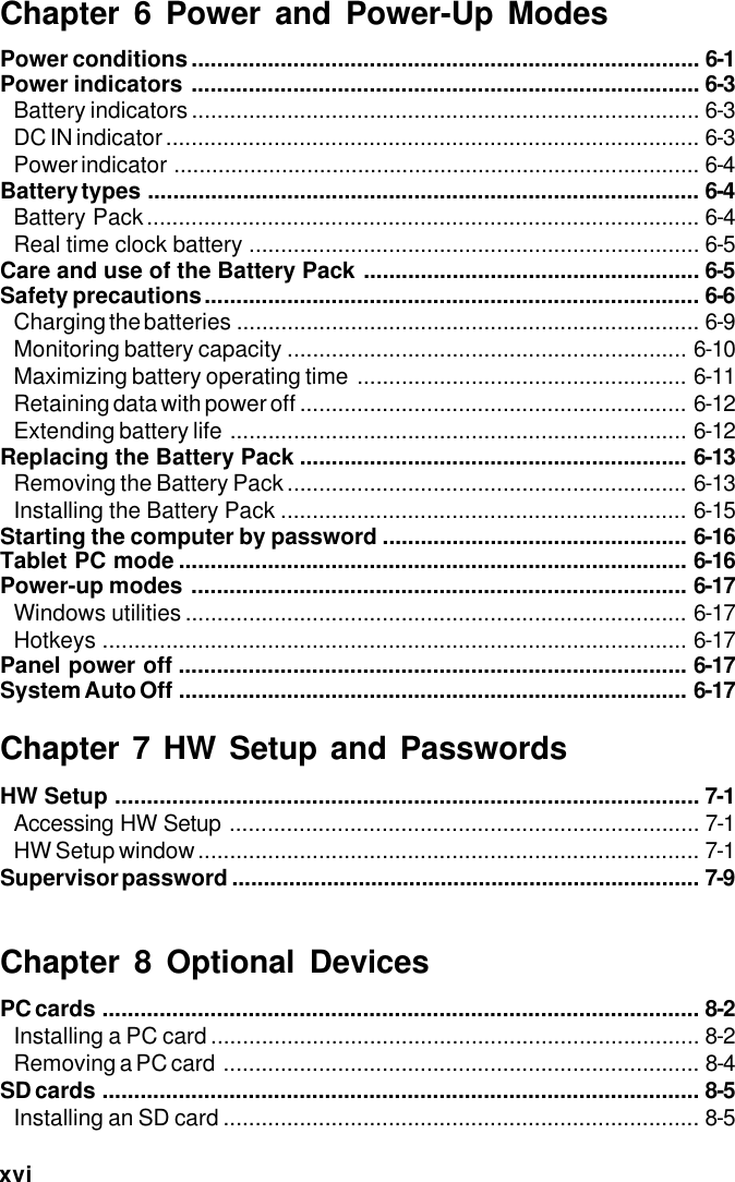
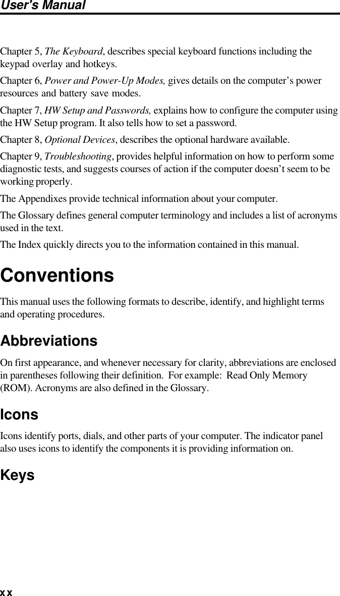
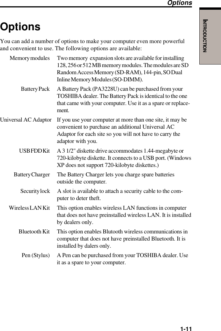
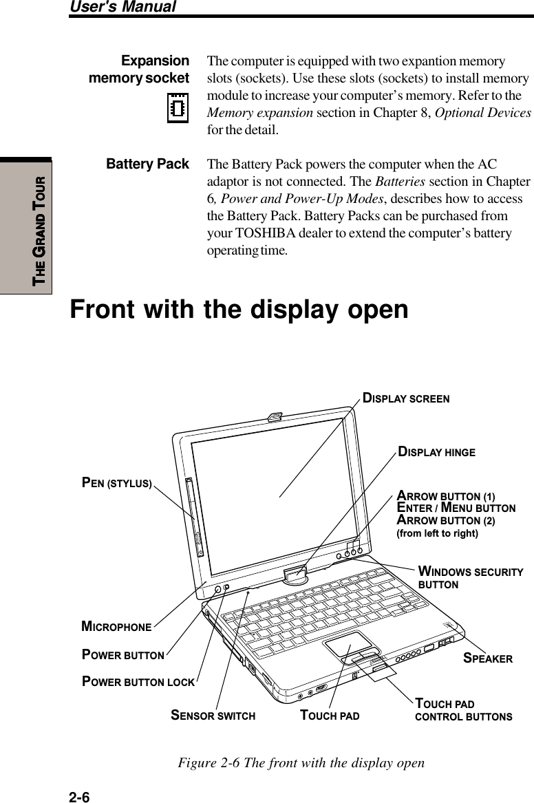
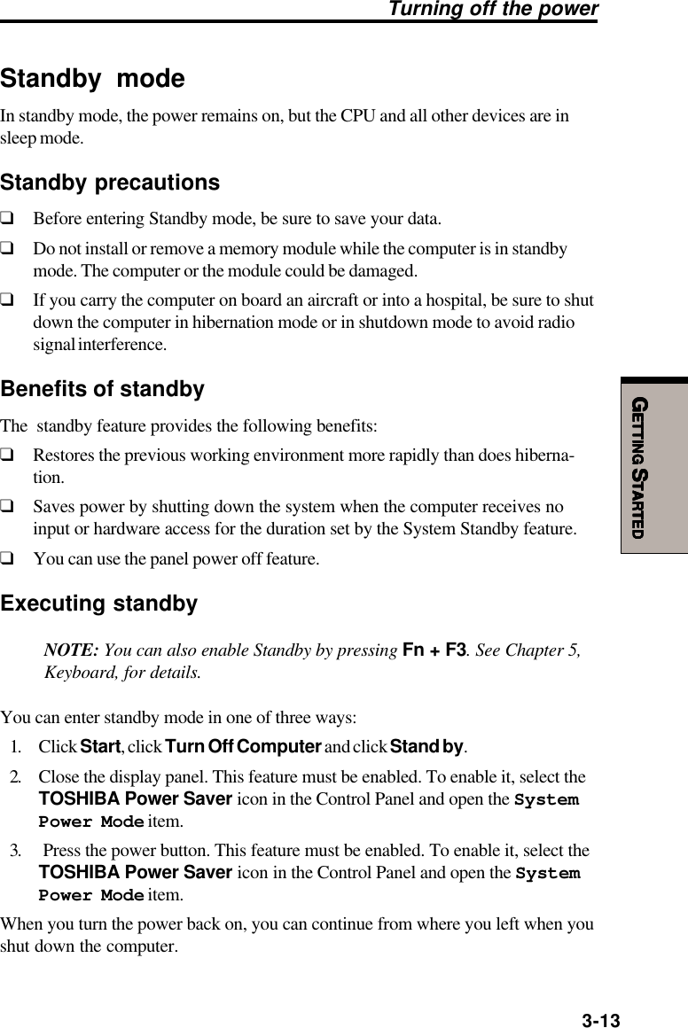
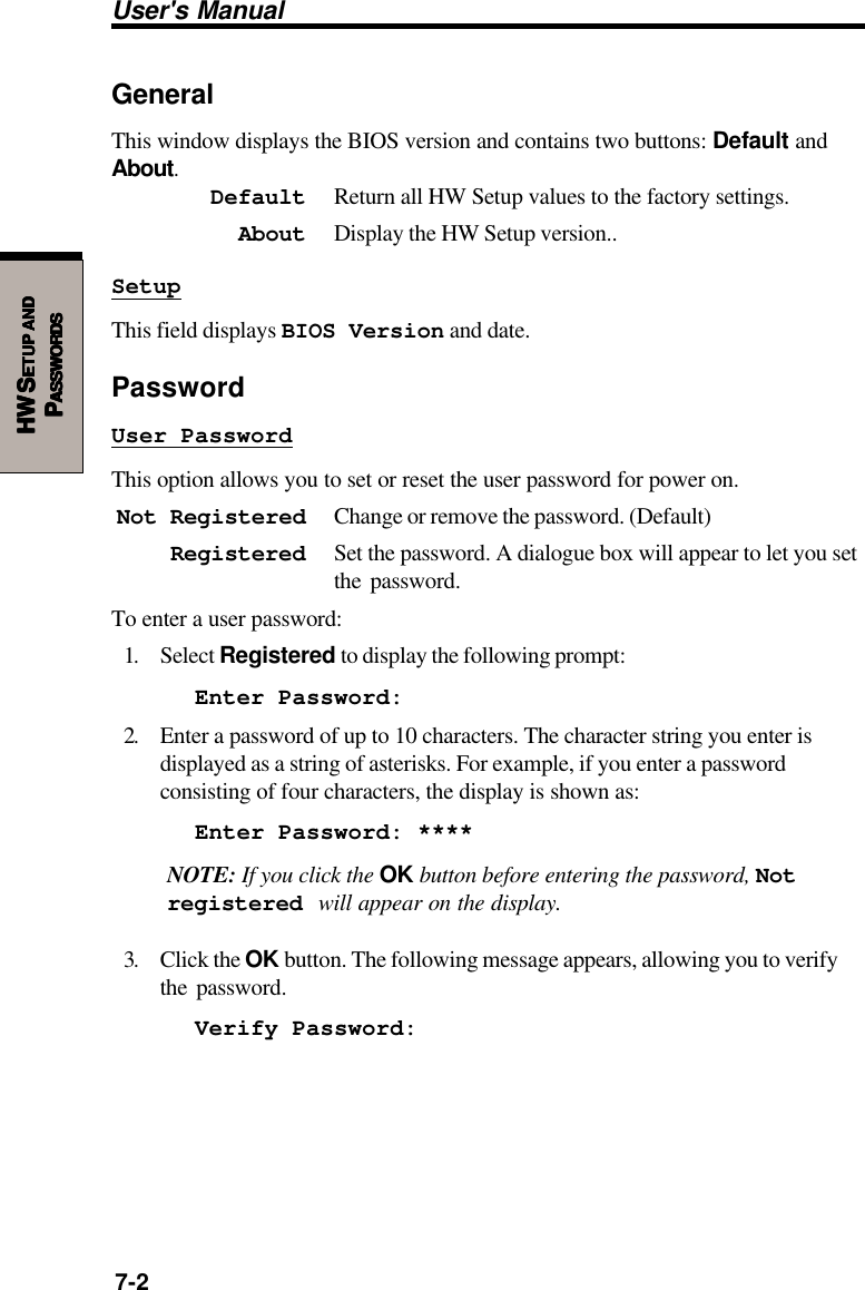
![6-5PPPPPOWEROWEROWEROWEROWER ANDANDANDANDANDPPPPPOWEROWEROWEROWEROWER-U-U-U-U-UPPPPP M M M M MODESODESODESODESODESTo ensure that the Battery Pack maintains its maximum capacity, operate thecomputer on battery power at least once a month until the Battery Pack is fullydischarged. Refer to Extending battery life in this chapter for procedures. If thecomputer is continuously operated on AC power, through an AC adaptor for anextended period, more than a month, the battery may fail to retain a charge. It maynot function efficiently over the expected life of the battery and the Battery LEDmay not indicate a low-battery condition.Real time clock batteryThe Real Time Clock (RTC) battery provides power for the internal real time clockand calendar. It also maintains the system configuration.If the RTC battery becomes completely discharged, the system loses this data andthe real time clock and calendar stop working. The following message appears whenyou turn on the power:*** Bad RTC battery ***Check system. Then press [F1] key . . . . . .CAUTION: The computer’s RTC battery is a lithium ion battery andshould be replaced only by your dealer or by a TOSHIBA servicerepresentative. The battery can explode if not properly replaced, used,handled or disposed of. Dispose of the battery as required by localordinances or regulations.Care and use of the Battery PackThe Battery Pack is a vital component of portable computing. Taking proper care ofit will help ensure longer operating time on battery power as well as a longer life foryour Battery Pack. Follow the instructions in this section carefully to ensure safeoperation and maximum performance.Care and use of the Battery Pack](https://usermanual.wiki/Dynabook/UPP350BT.Notebook-user-manual/User-Guide-301519-Page-115.png)
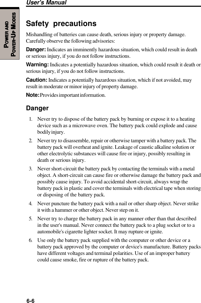

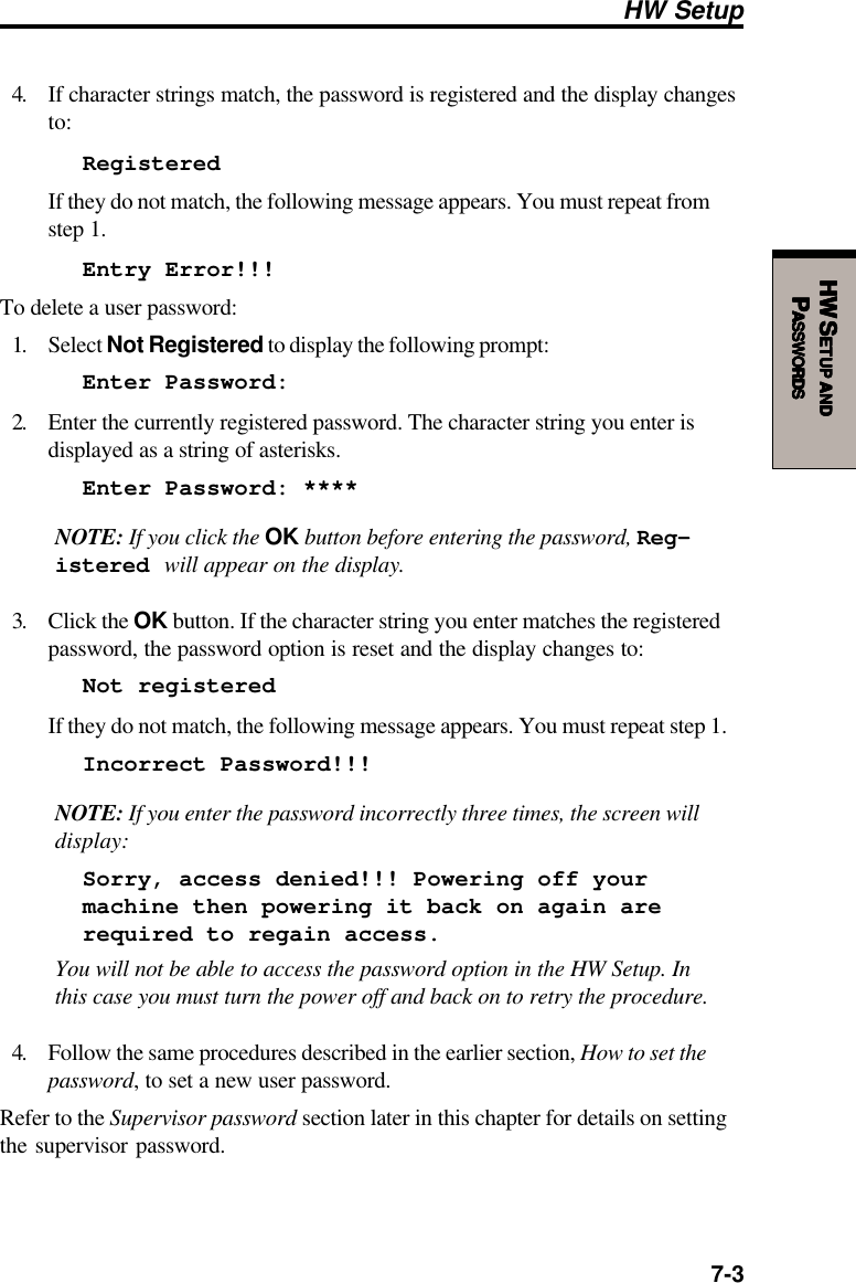
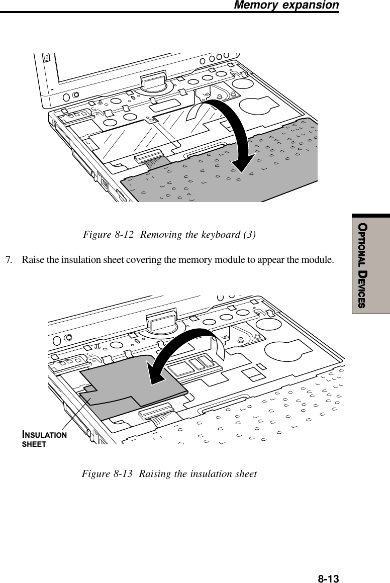
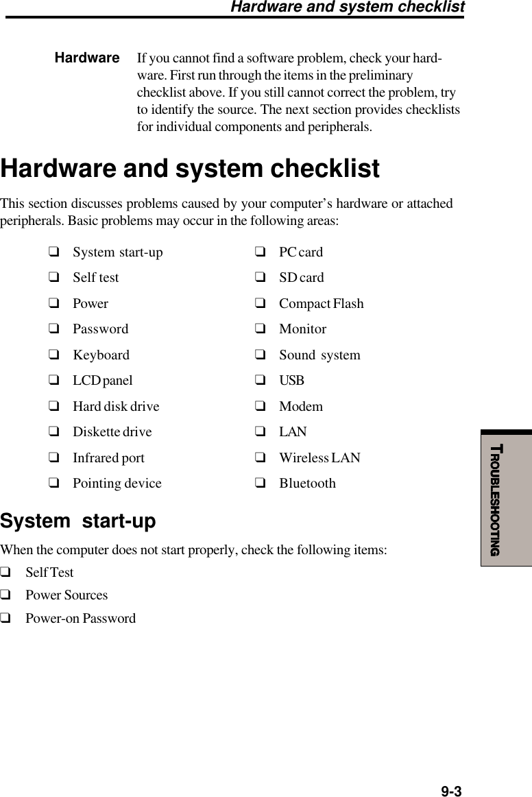
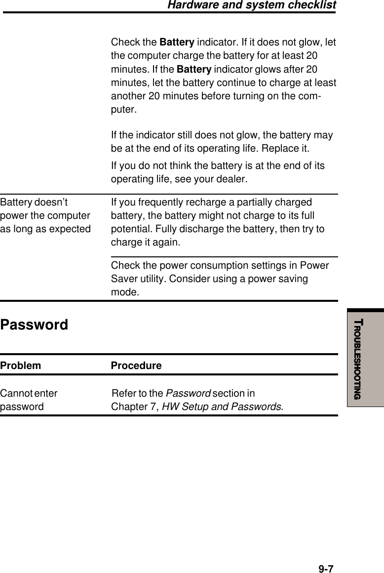
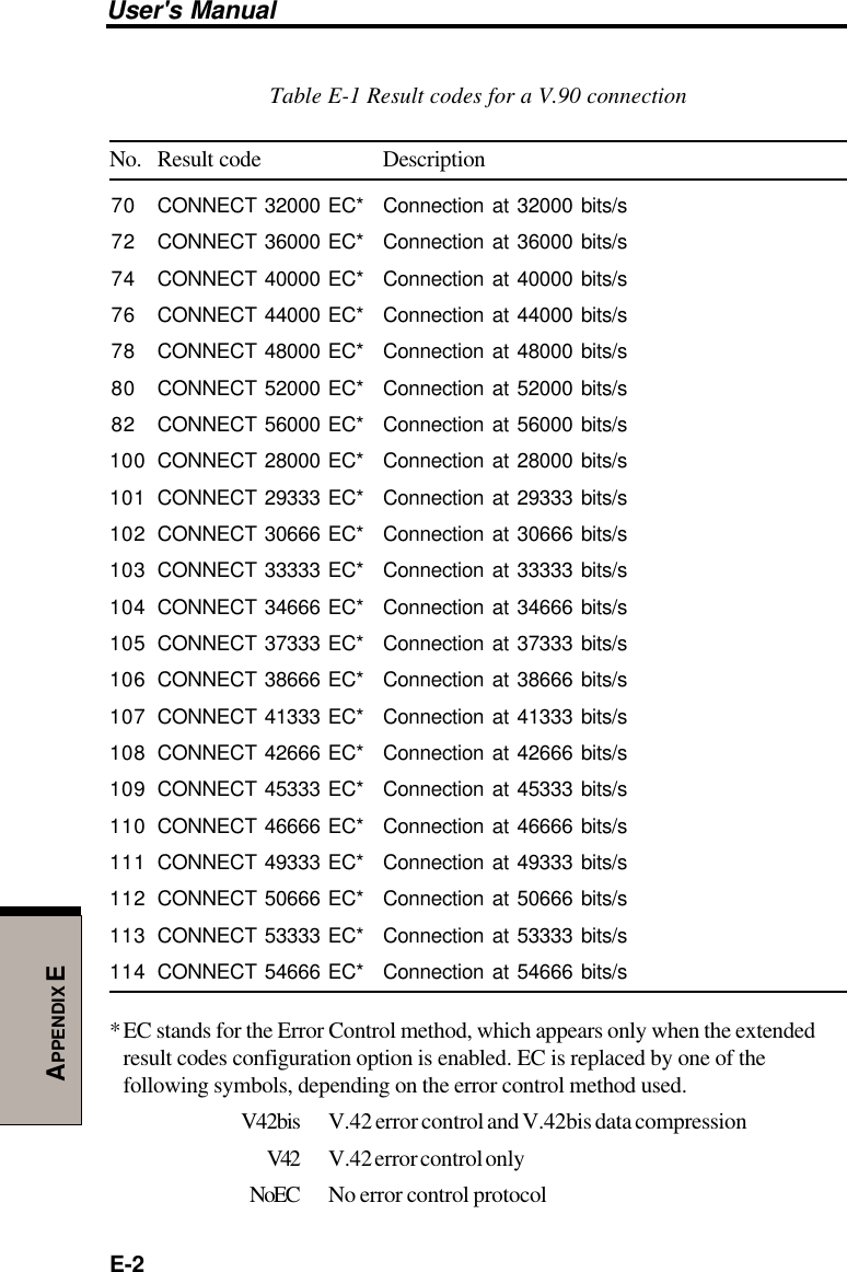
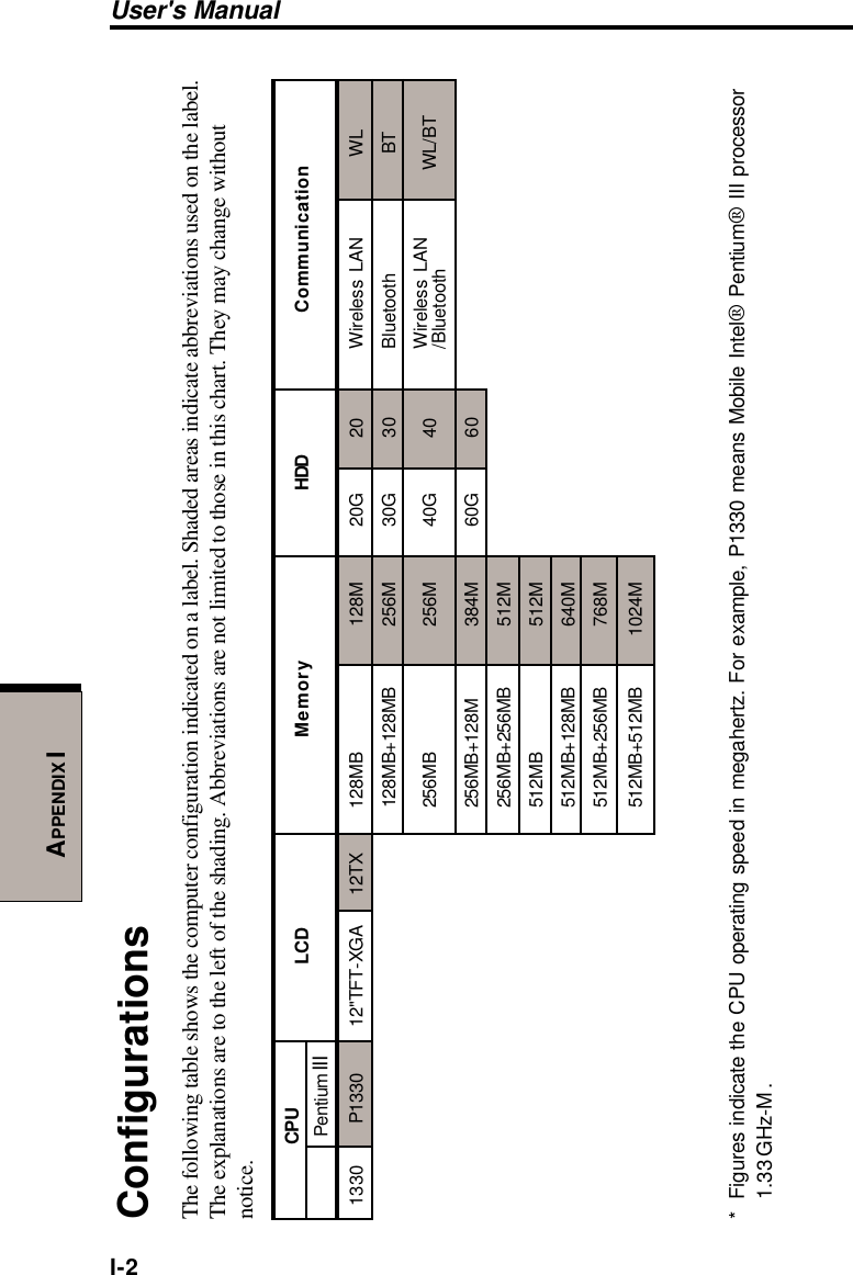
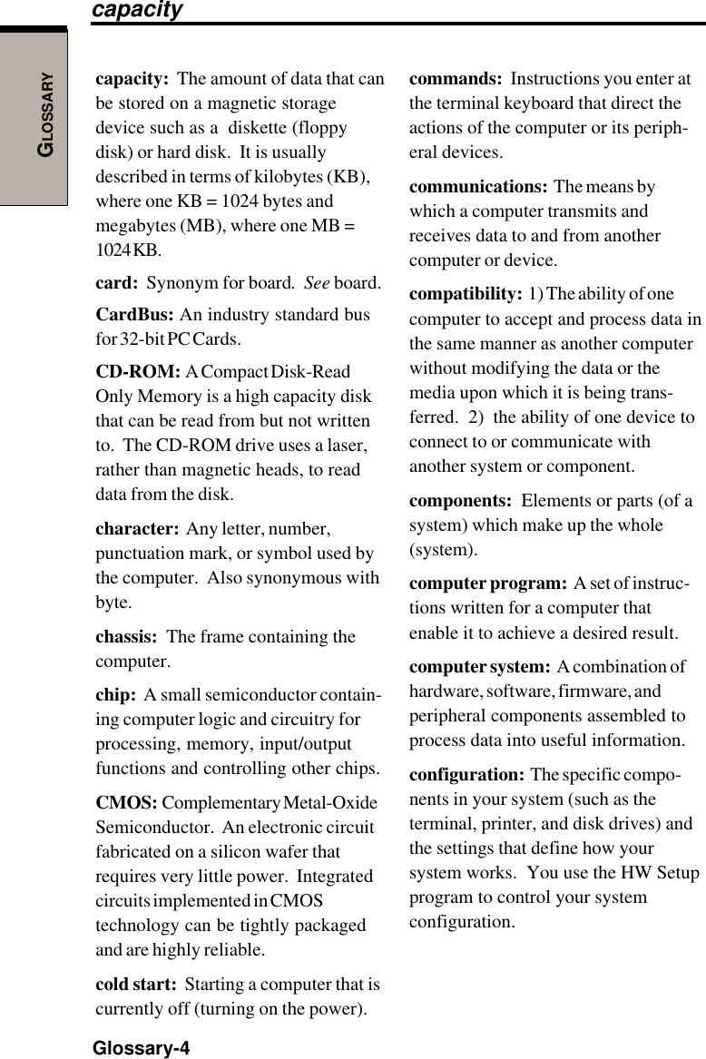
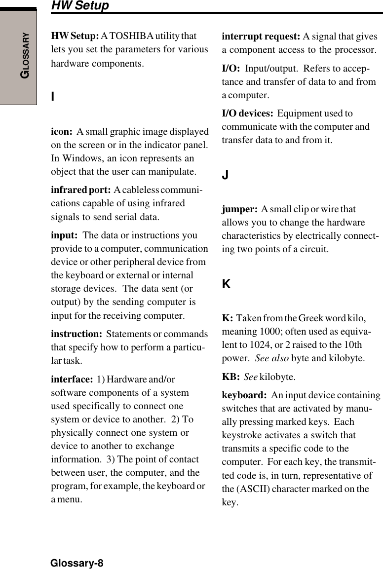
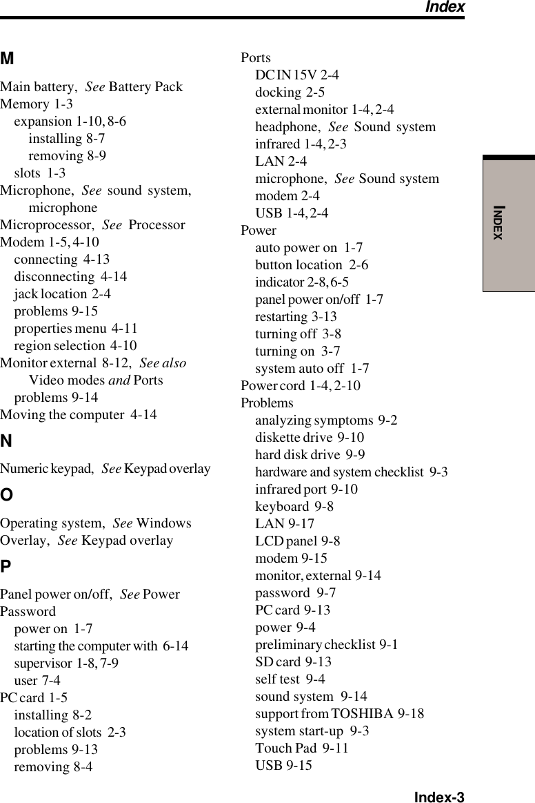
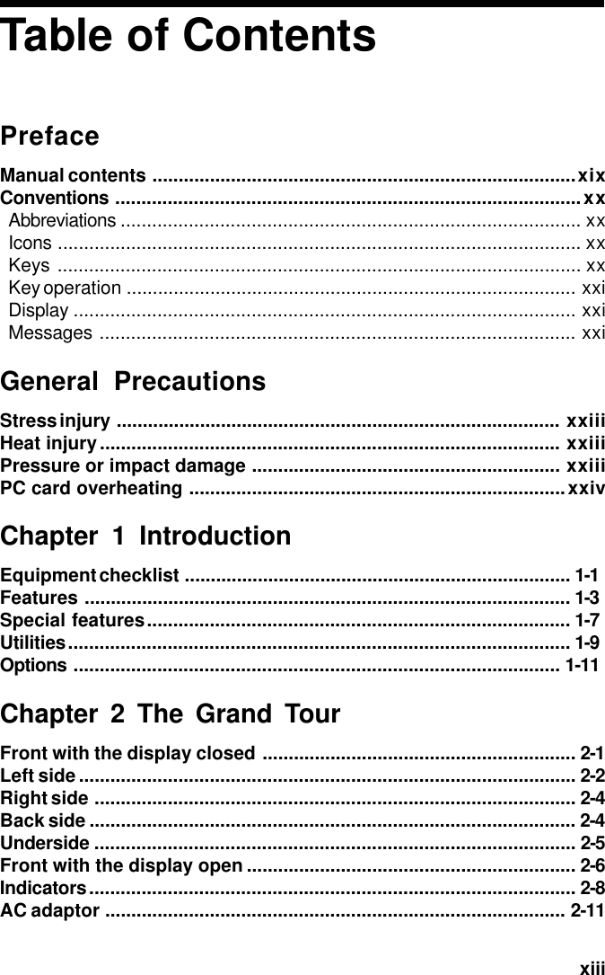
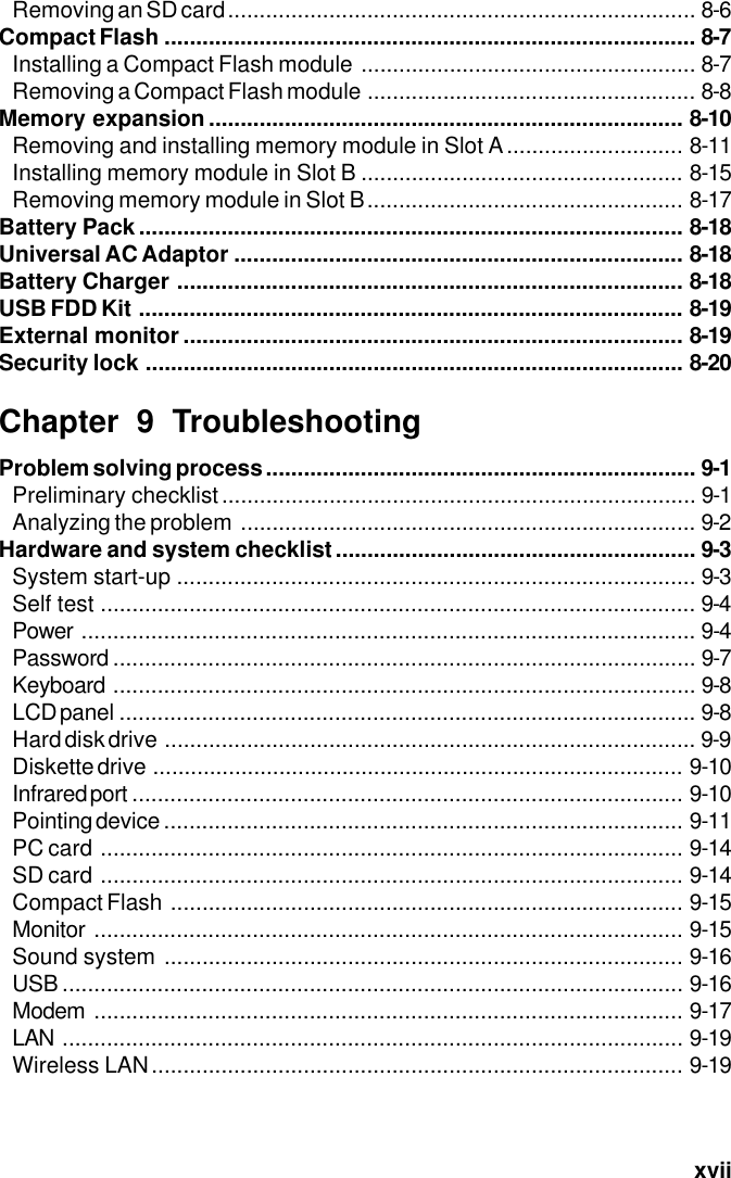
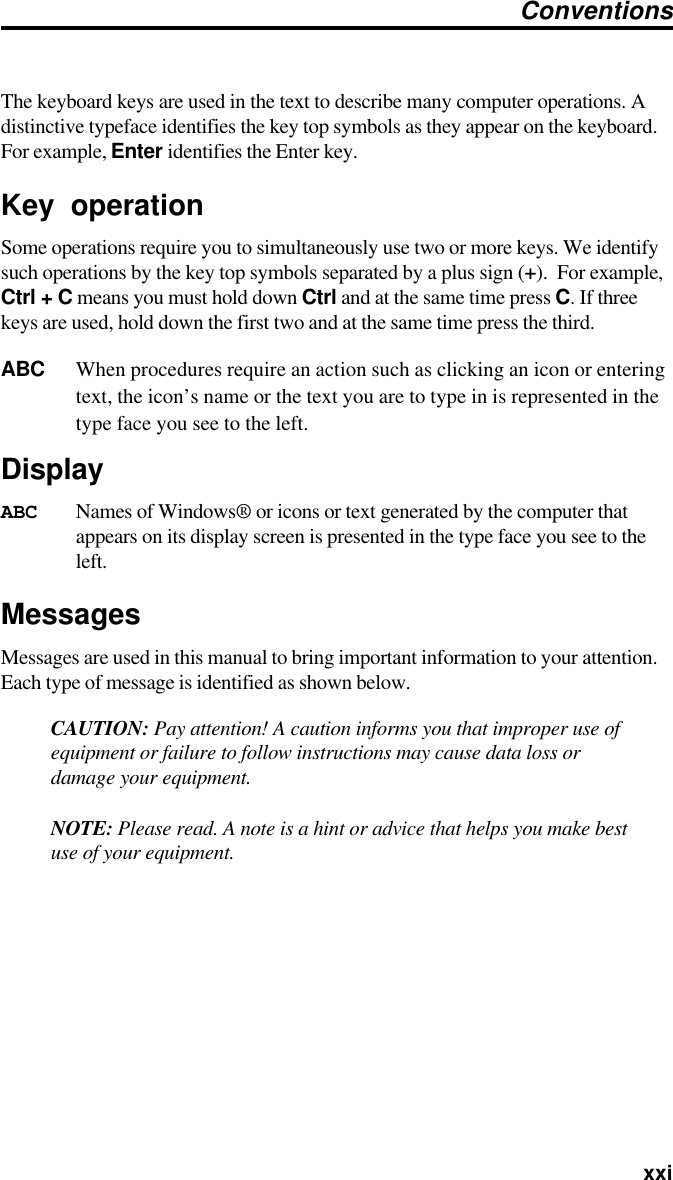
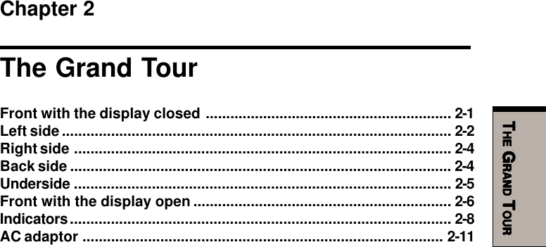
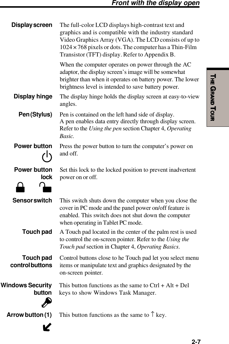
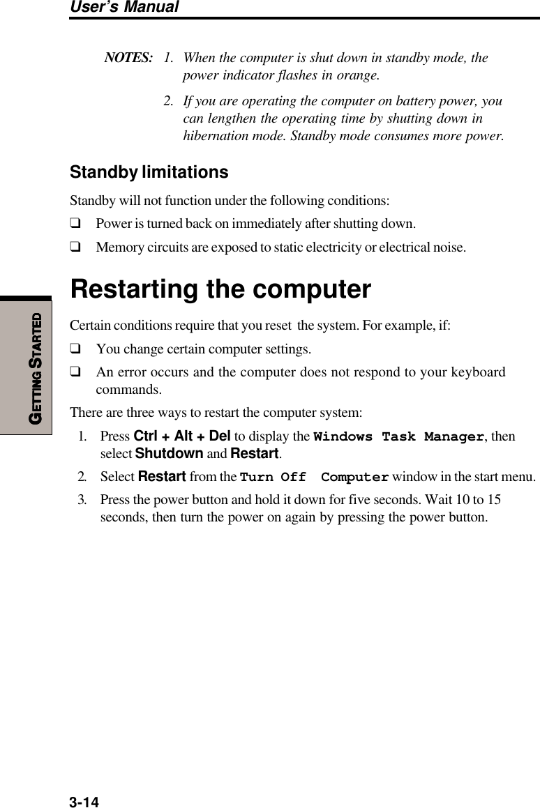
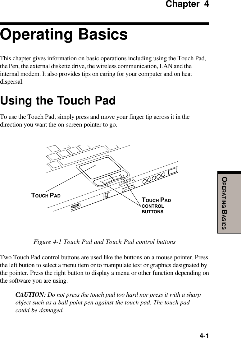
![7-7HW SHW SHW SHW SHW SETUPETUPETUPETUPETUP ANDANDANDANDANDPPPPPASSWORDSASSWORDSASSWORDSASSWORDSASSWORDSHW SetupThis procedure does not affect the settings.❑Use hot keys.1. Hold down F12 and boot the computer.2. The following menu will be displayed with the following icons: Built-in HDD,CD-ROM, FDD, Network (LAN), PCA (ATA) card boot.NOTE: A bar will appear only under the selected device.3. Use the left/right cursor keys to highlight the boot device you want and pressEnter.NOTES: 1. If a supervisor password is set, the menu above does notappear when you use the user password to start thecomputer.2. The selection method above does not change the bootpriority settings in HW Setup.3. If you press a key other than one of those above or if theselected device is not installed, the system will boot accordingto the current setting in HW Setup.Network Boot ProtocolThis feature sets the protocol to remotely boot from the network.[PXE] Sets PXE as the protocol. (Default)[RPL] Sets RPL as the protocol.NOTES: 1. PC card HDD boot is supported only by the PC card sloton the computer. Support is guaranteed only for TOSHIBAPC card HDDs.](https://usermanual.wiki/Dynabook/UPP350BT.Notebook-user-manual/User-Guide-301519-Page-137.png)