E F Johnson 2424110 VHF-FM PTT Transceiver User Manual CERTIFICATE OF COMPLIANCE
E. F. Johnson Company VHF-FM PTT Transceiver CERTIFICATE OF COMPLIANCE
UserManual.wiki
>
E F Johnson
>
2424110 User Manual
Manual
Navigation menu
Upload a User Manual
Namespaces
Wiki Guide
HTML
PDF
Info
Views
User Manual
Discussion / Help
Navigation

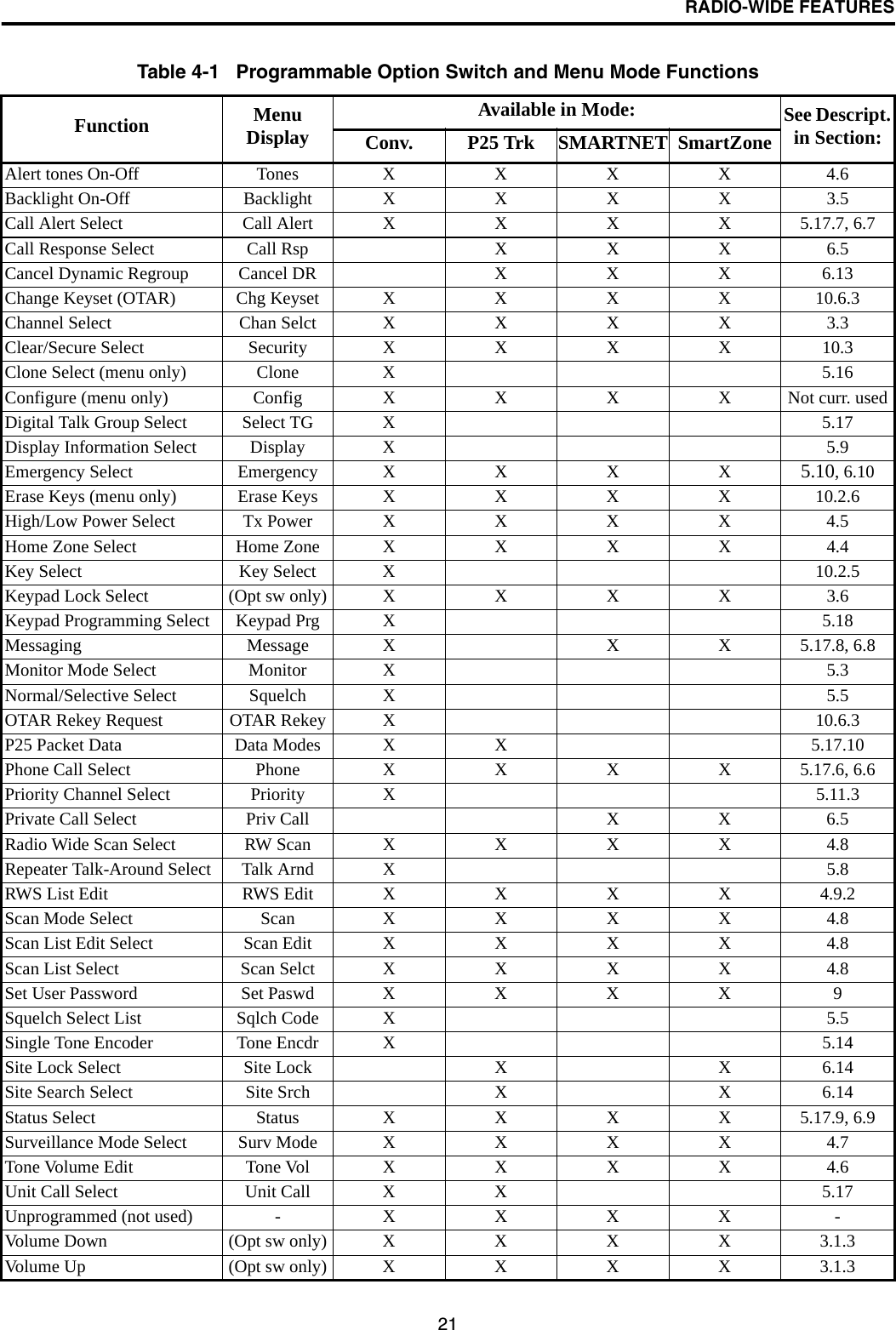
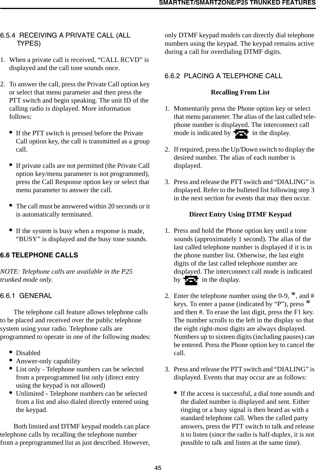
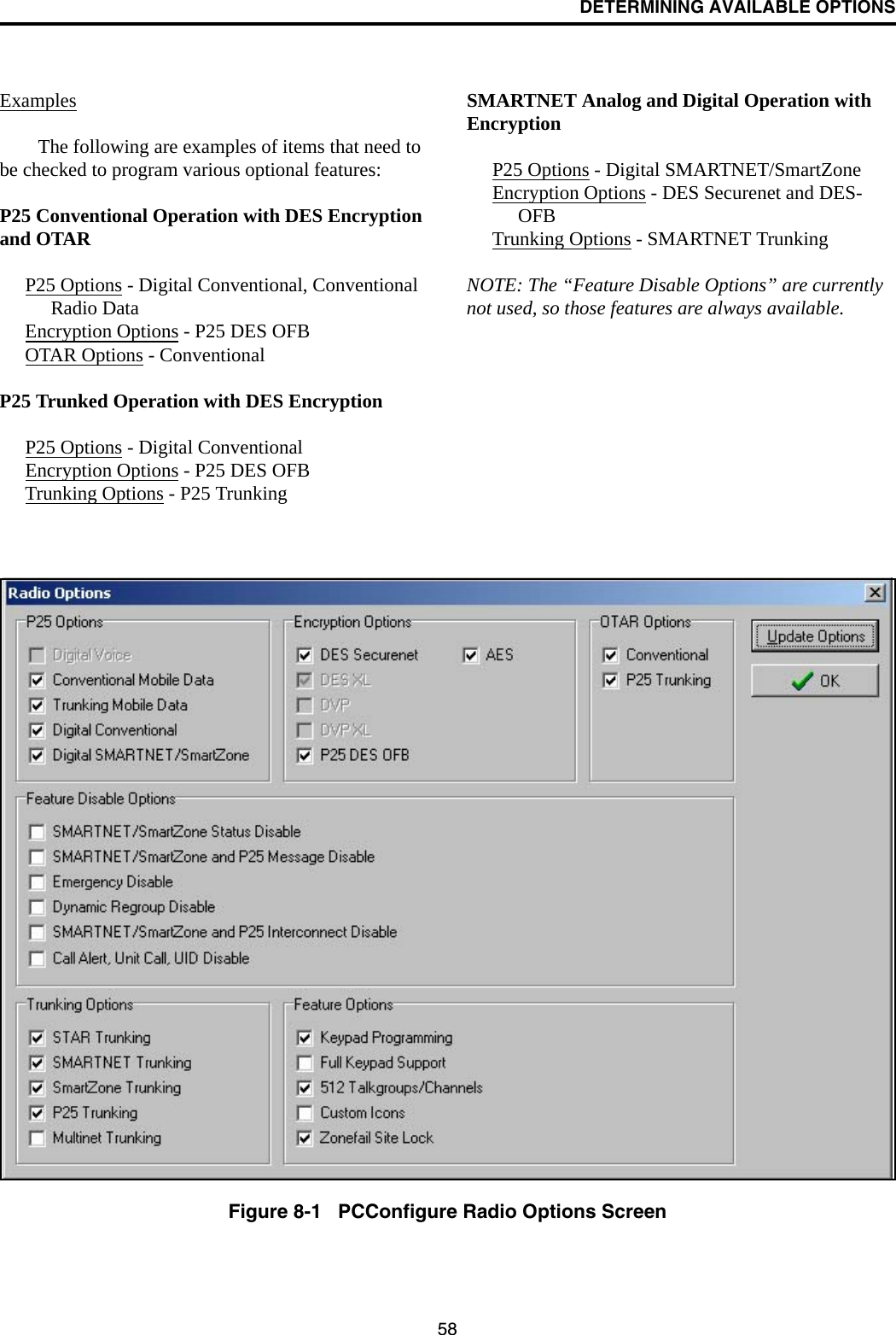
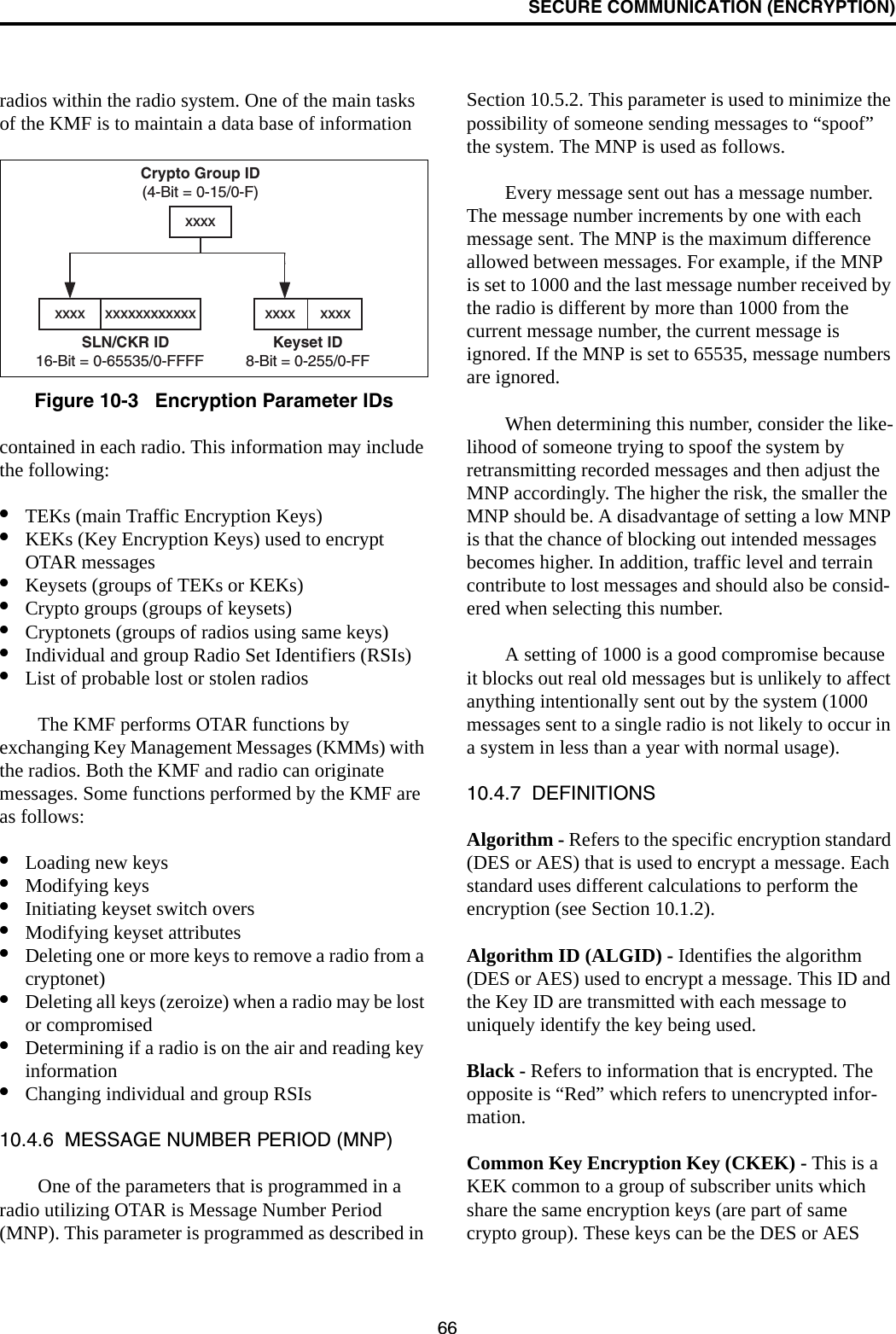
![57DETERMINING AVAILABLE OPTIONSSECTION 8 DETERMINING AVAILABLE OPTIONS8.1 GENERALThis manual describes the operation of all features that are currently available for the 41xx radio. However, many of these features are optional and therefore may not be available in your radio. For example, Project 25 trunked operation is optional and may not be available.Availability of optional features is controlled by factory programming of the control logic. Only those features that are specifically ordered and enabled in a particular radio are available for use and can be programmed. The features controlled by factory programming are as follows:P25 Options•P25 conventional data•P25 trunked data•P25 conventional operation•P25 trunked operationEncryption Options•DES •DES-XL •DES-OFB•AES OTAR Options•OTAR P25 conventional•OTAR P25 trunkedTrunking Options•STAR roaming with P25 trunked operation [1]•SMARTNET analog operation•SmartZone analog operation•Digital SMARTNET/SmartZoneFeature Options•Keypad programming (Federal Gov’t users only)•512 channels/talk groups (41xx only, currently standard)•DTMF Keypad support (4100 only)•Zonefail site lock[1] 4100 radios require that this option be enabled to roam across zone controller boundaries. Currently, the only operating mode that is stan-dard with all models is the conventional analog mode. Other variables such as frequency range are hardware dependent instead of software dependent.8.2 UPGRADING A RADIO WITH NEW OPTIONSThe capability exists to upgrade radios in the field with new features. A new feature can be purchased and a special encrypted code string keyed to the ESN (Electronic Serial Number) of the radio is then provided by the E.F. Johnson Company. This string is in the form of a computer file, and is downloaded to the radio using the PCConfigure programming soft-ware. This is initiated by clicking the “Update Options” button on the Radio Options screen shown in Figure 8-1.8.3 USING PCCONFIGURE TO DETERMINE OPTIONSTo determine what software options have been enabled in a particular radio, it is recommended that you use the PCConfigure™ programming software to read and display what options are installed. Proceed as follows:1. Connect the computer to the radio and start the program as described in the documentation included with the PCConfigure software.2. Select the 41xx radio type by selecting menu parameter Radio > Series > 4100 Portable.3. To display the Radio Options screen shown in Figure 8-1, select Transfer > Read Options From Radio.4. The check boxes indicate which options are enabled in the radio. They are for informational purposes only and cannot be edited.](https://usermanual.wiki/E-F-Johnson/2424110/User-Guide-497656-Page-58.png)