E F Johnson 2424110 VHF-FM PTT Transceiver User Manual CERTIFICATE OF COMPLIANCE
E. F. Johnson Company VHF-FM PTT Transceiver CERTIFICATE OF COMPLIANCE
Manual

Rhein Tech Laboratories Report #: 2004210
360 Herndon Parkway FCC ID: ATH2424110
Suite 1400 Model: 242-41xx
Herndon, VA 20170 Standards: FCC Part 90 &IC RSS-119
http://www.rheintech.com Date: December 13, 2004
. Page 50 of 70
APPENDIX J: USER’S MANUAL
Please refer to the Operator’s Manual.

DIGITAL/ANALOG PORTABLE RADIO
OPERATING
MANUAL
4100 SERIES
PORTABLE RADIO
■APCO Project 25
– Conventional
– Trunked
■SMARTNET®/
SmartZone®
■Analog (FM)
Conventional
VHF
UHF
700/800 MHZ
Part No. 242-41xx-xxx
Part Number 002-4100-xxxx
December 2004
4100

4100 SERIES PORTABLE
OPERATING MANUAL
■APCO PROJECT 25 CONVENTIONAL
■APCO PROJECT 25 TRUNKED
■SMARTNET®/SmartZone®
■ANALOG (FM) CONVENTIONAL
■VHF/UHF/800 MHz
Copyright© 2004 by the E.F. Johnson Company
The E.F. Johnson Company, which was founded in 1923, provides wireless communication
systems solutions for public safety, government, and commercial customers. The company
designs, manufactures, and markets conventional and trunked radio systems, mobile and
portable subscriber radios, repeaters, and Project 25 digital radio products. EFJohnson is a
wholly owned subsidiary of EFJ, Inc.
Viking Head/EFJohnson logo, PCConfigure™, and Call Guard® are trademarks of the E.F.
Johnson Company. SMARTNET®, SmartZone®, SecureNet™, Call Alert™, Enhanced Pri-
vate Conversation™, and Private Conversation II™ are trademarks of Motorola, Inc. All other
company and/or product names used in this manual are trademarks and/or registered trade-
marks of their respective manufacturer. The IMBE™ voice coding technology embodied in
this product is protected by intellectual property rights including patent rights of Digital Voice
Systems, Inc.
LAND MOBILE PRODUCT WARRANTY - The manufacturer’s warranty statement for this
product is available from your product supplier or from E.F. Johnson Company, 1440
Corporate Drive, Irving, TX 75038-2401. Phone toll free 1-800-328-3911.
Information in this manual is subject to change without notice.

3
TABLE OF CONTENTS
TABLE OF CONTENTS
SAFETY INFORMATION
• Federal Communications Commission Regulations 6
• Compliance with RF Exposure Standards . . . . . . . .6
• RF Exposure Compliance and Control Guidelines
and Operating Instructions. . . . . . . . . . . . . . . . . . . .7
• Contact Information. . . . . . . . . . . . . . . . . . . . . . . . .7
• Electromagnetic Interference. . . . . . . . . . . . . . . . . .7
• Usage Compatibility . . . . . . . . . . . . . . . . . . . . . . . .7
• Battery Disposal. . . . . . . . . . . . . . . . . . . . . . . . . . . .7
1 FEATURES
1.1 General Features . . . . . . . . . . . . . . . . . . . . . . . . . . .8
1.2 Conventional Features . . . . . . . . . . . . . . . . . . . . . . .8
1.3 SMARTNET/SmartZone Features . . . . . . . . . . . . .8
1.4 Project 25 Trunked Features . . . . . . . . . . . . . . . . . . 9
2 CONTROLS AND DISPLAY
2.1 Front Panel Controls . . . . . . . . . . . . . . . . . . . . . . .10
2.2 Top Panel Controls . . . . . . . . . . . . . . . . . . . . . . . .11
2.3 Side Controls . . . . . . . . . . . . . . . . . . . . . . . . . . . . .11
2.4 Display. . . . . . . . . . . . . . . . . . . . . . . . . . . . . . . . . .12
3 GENERAL OPERATION
3.1 Turning Power On and Setting Volume . . . . . . . .13
Power Up . . . . . . . . . . . . . . . . . . . . . . . . . . . . . 13
Standard and Soft Power Down . . . . . . . . . . . . 13
Setting Volume Level . . . . . . . . . . . . . . . . . . . . 13
3.2 Power-Up Password. . . . . . . . . . . . . . . . . . . . . . . .13
General . . . . . . . . . . . . . . . . . . . . . . . . . . . . . . . 13
Password Features. . . . . . . . . . . . . . . . . . . . . . . 14
3.3 Zone and Channel Select . . . . . . . . . . . . . . . . . . . .14
3.4 Low Battery Indication . . . . . . . . . . . . . . . . . . . . .15
General . . . . . . . . . . . . . . . . . . . . . . . . . . . . . . . 15
Battery Charging. . . . . . . . . . . . . . . . . . . . . . . . 16
3.5 Backlight . . . . . . . . . . . . . . . . . . . . . . . . . . . . . . . . 16
3.6 Keypad Lock . . . . . . . . . . . . . . . . . . . . . . . . . . . . .16
3.7 Setting Squelch . . . . . . . . . . . . . . . . . . . . . . . . . . .17
3.8 Transmit Disable . . . . . . . . . . . . . . . . . . . . . . . . . .17
3.9 Radio Operating Modes. . . . . . . . . . . . . . . . . . . . .17
General . . . . . . . . . . . . . . . . . . . . . . . . . . . . . . . 17
Conventional Mode. . . . . . . . . . . . . . . . . . . . . . 17
SMARTNET/SmartZone Mode . . . . . . . . . . . . 17
P25 Trunked Mode . . . . . . . . . . . . . . . . . . . . . . 18
Systems, Channels, and Zones . . . . . . . . . . . . . 18
4 RADIO-WIDE FEATURES
4.1 Option Switches . . . . . . . . . . . . . . . . . . . . . . . . . . 20
4.2 Menu Mode. . . . . . . . . . . . . . . . . . . . . . . . . . . . . . 20
4.3 Time-Out Timer . . . . . . . . . . . . . . . . . . . . . . . . . . 20
4.4 Home Zone/Channel Select . . . . . . . . . . . . . . . . . 22
4.5 Power Output Select. . . . . . . . . . . . . . . . . . . . . . . 22
4.6 Alert Tone Select . . . . . . . . . . . . . . . . . . . . . . . . . 22
4.7 Surveillance Mode . . . . . . . . . . . . . . . . . . . . . . . . 22
4.8 Scanning . . . . . . . . . . . . . . . . . . . . . . . . . . . . . . . . 23
Introduction . . . . . . . . . . . . . . . . . . . . . . . . . . . . 23
Priority Scanning . . . . . . . . . . . . . . . . . . . . . . . . 23
Radio Wide Scanning . . . . . . . . . . . . . . . . . . . . 23
Scan Hold Time. . . . . . . . . . . . . . . . . . . . . . . . . 23
Transmitting in the Scan Mode . . . . . . . . . . . . . 24
Nuisance Channel Add/Delete. . . . . . . . . . . . . . 24
4.9 Scan Lists . . . . . . . . . . . . . . . . . . . . . . . . . . . . . . . 24
Priority Scan Lists . . . . . . . . . . . . . . . . . . . . . . . 24
Radio Wide Scan Lists. . . . . . . . . . . . . . . . . . . . 26
5 CONVENTIONAL MODE FEATURES
5.1 Introduction . . . . . . . . . . . . . . . . . . . . . . . . . . . . . 27
5.2 Monitoring Before Transmitting . . . . . . . . . . . . . 27
5.3 Monitor Mode. . . . . . . . . . . . . . . . . . . . . . . . . . . . 27
5.4 Busy Channel Lockout . . . . . . . . . . . . . . . . . . . . . 27
5.5 Call Guard Squelch. . . . . . . . . . . . . . . . . . . . . . . . 28
Introduction . . . . . . . . . . . . . . . . . . . . . . . . . . . . 28
Call Guard Squelch Enable/Disable . . . . . . . . . 28
Tone Call Guard Squelch. . . . . . . . . . . . . . . . . . 28
Digital Call Guard Squelch . . . . . . . . . . . . . . . . 28
Selective Squelch Code Select. . . . . . . . . . . . . . 29
5.6 Penalty Timer . . . . . . . . . . . . . . . . . . . . . . . . . . . . 29
5.7 Conversation Timer . . . . . . . . . . . . . . . . . . . . . . . 29
5.8 Repeater Talk-Around . . . . . . . . . . . . . . . . . . . . . 30
5.9 Displaying Transmit/Receive Frequency . . . . . . . 30
5.10 Emergency Alarm and Call . . . . . . . . . . . . . . . . . 30
Introduction . . . . . . . . . . . . . . . . . . . . . . . . . . . . 30
Emergency Alarms . . . . . . . . . . . . . . . . . . . . . . 30
Emergency Calls . . . . . . . . . . . . . . . . . . . . . . . . 31
Emergency Man-Down Feature. . . . . . . . . . . . . 31
5.11 Conventional Mode Scanning . . . . . . . . . . . . . . 31
General. . . . . . . . . . . . . . . . . . . . . . . . . . . . . . . . 31
Transmitting in Scan Mode . . . . . . . . . . . . . . . . 32
Priority Channel Sampling . . . . . . . . . . . . . . . . 32
5.12 Standard Conventional Calls. . . . . . . . . . . . . 33
5.13 DTMF/ANI Signaling. . . . . . . . . . . . . . . . . . . . . . 33
5.14 Single Tone Encoder . . . . . . . . . . . . . . . . . . . . . . 33
5.15 MDC1200 Compatibility . . . . . . . . . . . . . . . . . . . 34

TABLE OF CONTENTS
4
5.16 Clone Mode . . . . . . . . . . . . . . . . . . . . . . . . . . . . . .34
General . . . . . . . . . . . . . . . . . . . . . . . . . . . . . . . 34
Wireless Cloning. . . . . . . . . . . . . . . . . . . . . . . . 34
Cloning Procedure . . . . . . . . . . . . . . . . . . . . . . 34
5.17 Project 25 Mode Features . . . . . . . . . . . . . . . . . . .35
Unit ID Code. . . . . . . . . . . . . . . . . . . . . . . . . . . 35
Group ID Code . . . . . . . . . . . . . . . . . . . . . . . . . 35
Network Access Code. . . . . . . . . . . . . . . . . . . . 35
P25 Group Calls . . . . . . . . . . . . . . . . . . . . . . . . 35
P25 Unit Calls. . . . . . . . . . . . . . . . . . . . . . . . . . 35
P25 Conventional Telephone Calls. . . . . . . . . . 36
Call Alert. . . . . . . . . . . . . . . . . . . . . . . . . . . . . . 37
Messaging . . . . . . . . . . . . . . . . . . . . . . . . . . . . . 38
Status Messaging . . . . . . . . . . . . . . . . . . . . . . . 38
P25 Packet Data . . . . . . . . . . . . . . . . . . . . . . . . 38
5.18 Keypad Programming . . . . . . . . . . . . . . . . . . . . . .38
Introduction. . . . . . . . . . . . . . . . . . . . . . . . . . . . 38
Menu Description . . . . . . . . . . . . . . . . . . . . . . . 39
Zone Password . . . . . . . . . . . . . . . . . . . . . . . . . 39
Zone Change Parameter . . . . . . . . . . . . . . . . . . 39
Channel Change Parameter. . . . . . . . . . . . . . . . 40
System Parameters . . . . . . . . . . . . . . . . . . . . . . 40
Channel Parameters . . . . . . . . . . . . . . . . . . . . . 40
6 SMARTNET/SMARTZONE/P25
TRUNKED FEATURES
6.1 Introduction . . . . . . . . . . . . . . . . . . . . . . . . . . . . . .42
6.2 Analog and Digital Operation . . . . . . . . . . . . . . . .42
6.3 Viewing Unit ID . . . . . . . . . . . . . . . . . . . . . . . . . .42
6.4 Standard Group Calls. . . . . . . . . . . . . . . . . . . . . . .42
Introduction. . . . . . . . . . . . . . . . . . . . . . . . . . . . 42
Placing a Standard Group Call . . . . . . . . . . . . . 42
Receiving a Standard Group Call . . . . . . . . . . . 42
6.5 Private (Unit-To-Unit) Calls . . . . . . . . . . . . . . . . .43
General . . . . . . . . . . . . . . . . . . . . . . . . . . . . . . . 43
Placing an Enhanced Private Conversation Call 43
Placing a Standard Private Conversation Call . 44
Receiving a Private Call (All Types) . . . . . . . . 45
6.6 Telephone Calls . . . . . . . . . . . . . . . . . . . . . . . . . . .45
General . . . . . . . . . . . . . . . . . . . . . . . . . . . . . . . 45
Placing a Telephone Call . . . . . . . . . . . . . . . . . 45
Answering a Telephone Call. . . . . . . . . . . . . . . 46
6.7 Call Alert . . . . . . . . . . . . . . . . . . . . . . . . . . . . . . .46
General . . . . . . . . . . . . . . . . . . . . . . . . . . . . . . . 46
Answering a Page . . . . . . . . . . . . . . . . . . . . . . . 46
Initiating a Page . . . . . . . . . . . . . . . . . . . . . . . . 47
6.8 Messaging . . . . . . . . . . . . . . . . . . . . . . . . . . . . . . .47
6.9 Sending Status Conditions. . . . . . . . . . . . . . . . . . .47
6.10 Emergency Alarm and Call . . . . . . . . . . . . . . . . . .47
Introduction. . . . . . . . . . . . . . . . . . . . . . . . . . . . 47
Emergency Alarms . . . . . . . . . . . . . . . . . . . . . . 48
Emergency Calls . . . . . . . . . . . . . . . . . . . . . . . . 48
Emergency Man-Down Feature. . . . . . . . . . . . . 49
6.11 Failsoft Operation. . . . . . . . . . . . . . . . . . . . . . . . . 49
6.12 SMARTNET/Smartzone/P25 Trunked Scanning Fea-
tures49
General. . . . . . . . . . . . . . . . . . . . . . . . . . . . . . . . 49
Priority Talk Group Sampling . . . . . . . . . . 49
6.13 Dynamic Regrouping . . . . . . . . . . . . . . . . . . . . . . 50
6.14 SmartZone and P25 Trunked Unique Features. . . 50
Introduction . . . . . . . . . . . . . . . . . . . . . . . . . . . . 50
Busy Override . . . . . . . . . . . . . . . . . . . . . . . . . . 50
Site Trunking . . . . . . . . . . . . . . . . . . . . . . . . . . . 50
Determining Current Site and Searching For New
Site 51
Locking/Unlocking a Site . . . . . . . . . . . . . . . . . 51
ZoneFail Site Lock . . . . . . . . . . . . . . . . . . . . . . 51
P25 Wide Area Scan . . . . . . . . . . . . . . . . . . . . . 51
7 MISCELLANEOUS
7.1 Supervisory Tones . . . . . . . . . . . . . . . . . . . . . . . . 53
7.2 Error Messages . . . . . . . . . . . . . . . . . . . . . . . . . . . 54
7.3 System Operator Programming . . . . . . . . . . . . . . 55
7.4 Speaking Into Microphone . . . . . . . . . . . . . . . . . . 56
7.5 Operation At Extended Range . . . . . . . . . . . . . . . 56
7.6 Licensing . . . . . . . . . . . . . . . . . . . . . . . . . . . . . . . 56
7.7 Radio Service . . . . . . . . . . . . . . . . . . . . . . . . . . . . 56
8 DETERMINING AVAILABLE OPTIONS
8.1 General . . . . . . . . . . . . . . . . . . . . . . . . . . . . . . . . . 57
8.2 Upgrading A Radio With New Options . . . . . . . . 57
8.3 Using PCConfigure To Determine Options . . . . . 57
9 PASSWORD DESCRIPTION
9.1 New Password Enhancements . . . . . . . . . . . . . . . 59
Introduction . . . . . . . . . . . . . . . . . . . . . . . . . . . . 59
9.2 Programming Passwords . . . . . . . . . . . . . . . . . . . 59
General. . . . . . . . . . . . . . . . . . . . . . . . . . . . . . . . 59
Lost Passwords . . . . . . . . . . . . . . . . . . . . . . . . . 59
Changing Password . . . . . . . . . . . . . . . . . . . . . . 59
Password Entry Procedure. . . . . . . . . . . . . . . . . 59
9.3 Password Description . . . . . . . . . . . . . . . . . . . . . . 60
User (Power-On) Passwords . . . . . . . . . . . . . . . 60
Download/Upload Passwords . . . . . . . . . . . . . . 60
Master Password . . . . . . . . . . . . . . . . . . . . . . . . 60
9.4 Zone Password . . . . . . . . . . . . . . . . . . . . . . . . . . . 60

TABLE OF CONTENTS
5
10 SECURE COMMUNICATION
(ENCRYPTION)
10.1 General . . . . . . . . . . . . . . . . . . . . . . . . . . . . . . . . .61
Introduction. . . . . . . . . . . . . . . . . . . . . . . . . . . . 61
Encryption Algorithms . . . . . . . . . . . . . . . . . . . 61
Encryption Available With Various Channel Types
61
FIPS and Non-FIPS Modes. . . . . . . . . . . . . . . . 61
10.2 Encryption Keys . . . . . . . . . . . . . . . . . . . . . . . . . .62
Introduction. . . . . . . . . . . . . . . . . . . . . . . . . . . . 62
Key and Algorithm IDs. . . . . . . . . . . . . . . . . . . 62
PID/SLN Key Management Modes . . . . . . . . . 62
Maintaining Keys in Memory. . . . . . . . . . . . . . 63
Encryption Key Select . . . . . . . . . . . . . . . . . . . 63
Encryption Key Erase . . . . . . . . . . . . . . . . . . . . 63
Encryption Icon Operation . . . . . . . . . . . . . . . . 63
10.3 Clear/Secure Strapping . . . . . . . . . . . . . . . . . . . . .63
Transmit Mode Options . . . . . . . . . . . . . . . . . . 63
Receive Mode Options. . . . . . . . . . . . . . . . 64
Talk Group Encryption Override . . . . . . . . . . . 64
10.4 OTAR (Over-The-Air Rekeying) . . . . . . . . . . . . .64
Introduction. . . . . . . . . . . . . . . . . . . . . . . . . . . . 64
Encryption Key Types . . . . . . . . . . . . . . . . . . . 65
Keysets. . . . . . . . . . . . . . . . . . . . . . . . . . . . . . . . 65
Crypto Groups . . . . . . . . . . . . . . . . . . . . . . . . . . 65
Key Management Facility . . . . . . . . . . . . . . . . . 65
Message Number Period (MNP) . . . . . . . . . . . . 66
Definitions . . . . . . . . . . . . . . . . . . . . . . . . . . . . . 66
10.5 Radio Setup For Encryption . . . . . . . . . . . . . . . . . 68
General Encryption Setup . . . . . . . . . . . . . . . . . 68
Additional Setup For OTAR . . . . . . . . . . . . . . . 69
10.6 Radio OTAR Capabilities. . . . . . . . . . . . . . . . . . . 69
SEM 4100/53xx, Standard 41xx . . . . . . . . . . . . 69
UCM Equipped 4100. . . . . . . . . . . . . . . . . . . . . 70
OTAR Option Switches. . . . . . . . . . . . . . . . . . . 70
INDEX . . . . . . . . . . . . . . . . . . . . . . . . . . . . . . . . 74

6
SAFETY INFORMATION
RF ENERGY EXPOSURE AWARENESS AND CONTROL INFORMATION, AND
OPERATIONAL INSTRUCTIONS FOR FCC OCCUPATIONAL USE REQUIREMENTS
Before Using Your Portable Two-Way Radio, Read
This Important RF Energy Awareness And Control
Information And Operational Instructions To
Ensure Compliance With The FCC’s RF Exposure
Guidelines.
NOTICE: This radio is intended for use in occupa-
tional/controlled conditions where users have full
knowledge of their exposure and can exercise control
over their exposure to meet FCC limits. This radio
device is NOT authorized for general population,
consumer, or any other use.
This two-way radio uses electromagnetic energy
in the radio frequency (RF) spectrum to provide
communications between two or more users over a
distance. It uses radio frequency (RF) energy or radio
waves to send and receive calls. RF energy is one form
of electromagnetic energy. Other forms include, but
are not limited to, electric power, sunlight and x-rays.
RF energy, however, should not be confused with
these other forms of electromagnetic energy, which
when used improperly can cause biological damage.
Very high levels of x-rays, for example, can damage
tissues and genetic material.
Experts in science, engineering, medicine, health
and industry work with organizations to develop stan-
dards for exposure to RF energy. These standards
provide recommended levels of RF exposure for both
workers and the general public. These recommended
RF exposure levels include substantial margins of
protection. All two-way radios marketed in North
America are designed, manufactured and tested to
ensure they meet government established RF expo-
sure levels. In addition, manufacturers also recom-
mend specific operating instructions to users of two-
way radios. These instructions are important because
they inform users about RF energy exposure and
provide simple procedures on how to control it. Please
refer to the following web sites for more information
on what RF energy exposure is and how to control
your exposure to assure compliance with established
RF exposure limits.
•http://www.fcc.gov/oet/rfsafety/rf-faqs.html
•http://www.osha.gov/SLTC/radiofrequencyradia-
tion/index.html
FEDERAL COMMUNICATIONS COMMISSION
REGULATIONS
The FCC rules require manufacturers to comply
with the FCC RF energy exposure limits for portable
two-way radios before they can be marketed in the U.S.
When two-way radios are used as a consequence of
employment, the FCC requires users to be fully aware of
and able to control their exposure to meet occupational
requirements. Exposure awareness can be facilitated by
the use of a product label directing users to specific user
awareness information. Your EFJohnson two-way radio
has a RF exposure product label. Also, your EFJohnson
user manual, or product manual, or separate safety
booklet includes information and operating instructions
required to control your RF exposure and to satisfy
compliance requirements.
COMPLIANCE WITH RF EXPOSURE
STANDARDS
Your EFJohnson two-way radio is designed and
tested to comply with a number of national and interna-
tional standards and guidelines (listed below) for human
exposure to radio frequency electromagnetic energy. This
radio complies with the IEEE and ICNIRP exposure
limits for occupational/controlled RF exposure environ-
ment at operating duty factors of up to 50% transmitting
and is authorized by the FCC for occupational use only.
In terms of measuring RF energy for compliance with the
FCC exposure guidelines, your radio radiates measurable
RF energy only while it is transmitting (during talking),
not when it is receiving (listening) or in standby mode.
NOTE: The approved batteries supplied with this radio
are rated for a 5-5-90 duty factor (5% talk-5% listen -
90% standby), even though this radio complies with the
FCC occupational RF exposure limits and may operate
at duty factors of up to 50% talk.
Your EFJohnson two-way radio complies with the
following RF energy exposure standards and guidelines:
•United States Federal Communications Commission,
Code of Federal Regulations; 47 CFR §§ 1.1307,
1.1310, 2.1091 and 2.1093
•American National Standards Institute (ANSI) / Insti-
tute of Electrical and Electronic Engineers (IEEE)
C95. 1-1992

SAFETY INFORMATION
7
•Institute of Electrical and Electronic Engineers (IEEE)
C95.1-1999 Edition
RF EXPOSURE COMPLIANCE AND CONTROL
GUIDELINES AND OPERATING INSTRUCTIONS
To control your exposure and ensure compliance
with the occupational/controlled environment exposure
limits, always adhere to the following procedures.
Guidelines:
•Do not remove the RF Exposure Label from the
device.
•User awareness instructions should accompany the
device when it is transferred to other users.
•Do not use this device if the operational requirements
described herein are not met.
Operating Instructions:
•Transmit no more than the rated duty factor of 50% of
the time. To transmit (talk), push the Push-To-Talk
(PTT) button. To receive calls, release the PTT button.
Transmitting 50% of the time, or less, is important
because this radio generates measurable RF energy
exposure only when transmitting (in terms of
measuring for standards compliance).
•Hold the radio in a vertical position in front of face
with the microphone (and the other parts of the radio,
including the antenna) at least one inch (2.5 cm) away
from the nose. Keeping the radio at the proper distance
is important because RF exposures decrease with
distance from the antenna. The antenna should be kept
away from eyes.
•When worn on the body, always place the radio in an
EFJohnson approved clip, holder, holster, case, or
body harness for this product. Using approved body-
worn accessories is important because the use of
EFJohnson or other manufacturer’s non-approved
accessories may result in exposure levels which
exceed the FCC’s occupational/controlled environ-
ment RF exposure limits.
•If you are not using a body-worn accessory and are not
using the radio in the intended use position in front of
the face, then ensure the antenna and the radio are kept
at least one inch (2.5 cm) from the body when trans-
mitting. Keeping the radio at the proper distance is
important because RF exposures decrease with
increasing distance from the antenna.
•Use only EFJohnson approved supplied or replace-
ment antennas, batteries, and accessories. Use of non-
EFJohnson approved antennas, batteries, and accesso-
ries may exceed the FCC RF exposure guidelines.
•For a list of EFJohnson approved accessories, see the
service manual or marketing accessory lists or contact
the E.F. Johnson Company
CONTACT INFORMATION
Toll-Free: 1-800-328-3911
FAX: 972-818-0639
E-Mail: customerservice@efjohnson.com. You can also
e-mail a person directly if you know their first initial/last
name (example: jsmith@efjohnson.com).
You may also contact the Customer Service Depart-
ment by mail. Please include all information that may be
helpful in solving your problem. The mailing address is
as follows:
E.F. Johnson Company
Customer Service Department
1440 Corporate Drive
Irving, TX 75038-2401
ELECTROMAGNETIC INTERFERENCE
This device complies with Part 15 of the FCC rules.
Operation is subject to the condition that this device does
not cause harmful interference. In addition, changes or
modification to this equipment not expressly approved
by the E.F. Johnson Company could void the user’s
authority to operate this equipment (FCC Rules, 47CFR
Part 15.19).
USAGE COMPATIBILITY
DO NOT operate it in areas that are sensitive to RF
energy such as aircraft, hospitals, blasting sites, and fuel
storage sites. Areas with potentially flammable atmo-
spheres are usually, but not always, clearly posted. These
may include gas stations, fuel and chemical storage and
transfer stations, below deck on boats, and areas where
the air contains flammable chemicals or particles such as
grain dust or metal powders.
BATTERY DISPOSAL
Dispose of the nickel metal-hydride (NiMH) battery
used by this radio in accordance with local regulations.
DO NOT dispose of it in fire because it can explode.
Also, do not short the terminals because it may become
very hot.

8
FEATURES
SECTION 1 FEATURES
NOTE: The availability of many of the following
features is controlled by factory coding of your radio,
installed options, firmware version, and field
programming. Refer to Section 8 for more information.
1.1 GENERAL FEATURES
•The following operating modes are programmable:
– Conventional analog
– Conventional Project 25 (digital)
– Trunked Project 25 (digital)
– SMARTNET™/SmartZone® trunked (analog
or digital)
•Up to 32 zones with 16 channels each (512 channels
total) are standard.
•Large graphic display with backlight
•16-position channel select switch
•3-position rotary option switch
•Up to 9 (limited keypad) or 21 (DTMF keypad)
programmable option switches
•Each option button programmable with a different
function for each operating mode (Conventional,
SMARTNET/SmartZone, Trunked P25)
•Menu mode
•AES 256-bit FIPS 140-2 approved encryption
available on P25/digital channels
•DES/DES-XL 64-bit encryption available on analog
channels, DES-OFB on digital channels (see
Section 10).
•Emergency calls for high priority system access
•Priority (standard) and Radio Wide scan modes with
user programmable scan lists
•User selectable high and low power output
•Surveillance mode
•Time-out timer
•Keypad lock to prevent accidental key presses
•Power up password to prevent unauthorized use.
•Programmable and user adjustable tone volume
•Programmable minimum volume level
•Soft power down to prevent accidental power off
•Operates on both wide and narrow band channels
1.2 CONVENTIONAL FEATURES
•Up to 512 channels or talk groups programmable
•Repeater talk-around
•Carrier or Call Guard® (CTCSS/DCS) controlled
squelch on analog channels, NAC and talk group
IDs on P25 channels.
•Normal/selective squelch selectable by option
switch or menu
•Monitor mode selectable by option switch or menu
•Penalty and conversation timers
•Dual priority channel sampling when scanning
(analog and digital channels)
•Busy channel lockout (transmit disable on busy)
•Unit calls on P25 channels
•Telephone calls on P25 channels with overdial.
•Cloning capability (wireless or using cable)
•Emergency alarms and calls to alert a dispatcher of
an emergency condition.
•Single tone encoder controllable by user on analog
channels
•ANI (Automatic Number Identification) on analog
channels
•MDC1200 ANI and Emergency Alert support.
•Call Alert™ on P25 channels (send and receive
pages).
•Predefined messages (up to 16) can be sent to a
dispatcher (P25 mode only)
•Predefined status conditions (up to 8) can be sent to
a dispatcher (P25 mode only)
•OTAR (Over-The-Air-Rekeying) compatible (P25
channels only).
•Keypad programming with password access
(Federal Government users only)
1.3 SMARTNET/SMARTZONE FEATURES
•Up to 512 talk groups programmable (channels
select talk groups)
•Group, Enhanced Private Conversation™, standard
Private Conversation, and Telephone calls
•Emergency alarms to alert a dispatcher of
emergency conditions
•Emergency calls for high priority system access
•Failsoft operation on a predefined conventional
channel if trunked system fails
•Priority group calls detected while listening to other
group calls when scanning
•Call Alert™ (send and receive pages)
•Predefined messages (up to 16) can be sent to a
dispatcher

FEATURES
9
•Predefined status conditions (up to 8) can be sent to
a dispatcher
•Dynamic regrouping (dispatcher can automatically
gather users on a channel to receive a message)
•Roaming (SmartZone only)
1.4 PROJECT 25 TRUNKED FEATURES
•Up to 512 talk groups programmable (channels
select talk groups)
•Group and Unit Calls
•Telephone calls with overdial
•Emergency alarms to alert a dispatcher of
emergency conditions
•Emergency calls for high priority system access
•Failsoft operation on a predefined conventional
channel if trunked system fails
•Priority group calls detected while listening to other
group calls when scanning
•Call Alert™ (send and receive pages)
•Predefined status conditions (up to 8) can be sent to
a dispatcher
•Dynamic regrouping (dispatcher can automatically
gather users on a channel to receive a message)
•Roaming

10
CONTROLS AND DISPLAY
SECTION 2 CONTROLS AND DISPLAY
Figure 2-1 Front Panel Controls
2.1 FRONT PANEL CONTROLS
NOTE: The location of these controls is shown in
Figure 2-1.
Microphone - The microphone is located behind the
small opening shown in Figure 2-1. For best results,
hold the radio 2-3 inches from you mouth and speak at
a normal conversational level. Do not shout since it
distorts your voice and does not increase range.
Display - This is a graphical LCD (Liquid Crystal
Display). The display backlight can be programmed to
turn on when any key is pressed or when the Backlight
option switch is pressed or menu parameter selected
(see Section 3.5).
Up/Down Switch - Selects zones when multiple zones
are programmed (see Section 3.3). Pressing the upper
part of the switch selects the next higher number and
pressing the lower part selects the next lower number.
This control also provides up/down select in the menu
mode and in other modes when up/down select is
required.
F1 - In menu mode (see Section 4.2), functions as a
step back and exit switch. If menu mode is not used, it
is a programmable option switch.
F2 - Selects the menu mode when that mode is
enabled by programming. Also functions as an Enter
or Select switch in the menu and other modes. If menu
mode is not used, it is a programmable option switch.
F3, F4 - Programmable option switches.

CONTROLS AND DISPLAY
11
DTMF Keypad - The full keypad DTMF models
include the 12 keys required to dial telephone and unit
ID numbers.
Speaker - The radio speaker is located near the
bottom of the front panel. When a speaker/microphone
is used, it is automatically detected when the Opt Sel 1
line of the accessory connector is pulled low. The logic
then automatically disables the internal speaker.
Figure 2-2 Top Panel Controls
2.2 TOP PANEL CONTROLS
Multi-Function Indicator - Indicates the following
conditions:
Steady Red - Transmitter keyed.
Flashing Red - Low battery in receive mode.
Steady Green - Carrier detected in receive mode.
NOTE: This indicator is disabled if the Surveillance
mode is programmed (see Section 4.7).
On-Off/Volume - Turning the knob clockwise turns
power on and sets the volume level. Turning it coun-
terclockwise to the detent turns power off. The
minimum volume level can be set by programming.
Soft power down can be programmed as described in
Section 3.1.2, and the volume control can be disabled
as described in Section 3.1.3.
Channel Switch - This 16-position switch selects up
to 16 channels in the current zone. Additional zones
can be programmed to allow up to 512 channels to be
selected by this switch. This control can be disabled as
described in Section 3.3.
Rotary Option Switch - This is a three-position
switch that can be programmed to control various
options. The “A” position is “on” and the “B” and “C”
positions are “off” (see Section 4.1). When this switch
is programmed to select zones, “A” selects Zone 1,
“B” Zone 2, and “C” Zone 3 if applicable.
Antenna Connector - Connection point for the
antenna. Make sure the antenna is tight before using
the radio.
Emergency Switch - This switch or some other option
switch can be programmed as an Emergency switch to
alert a dispatcher of an emergency condition. Refer to
Sections 5.10 and 6.10 for more information. This
switch can also be programmed for other functions.
2.3 SIDE CONTROLS
Figure 2-3 Side Controls and Jacks
PTT (Push-To-Talk) Switch - This switch is pressed
to turn the transmitter on to transmit a message. It is
then released to listen. Transmitting is indicated when
the top panel indicator is constant red or is
displayed (surveillance mode only, see Section 4.7).
Option Switches 1, 2, and 3 - Each of these switches
can be programmed to control a specific function (see
Section 4.1). In addition, they can be programmed for
CONTROLS AND DISPLAY
12
soft power down (see Section 3.1.2). These switches
can also be temporarily disabled by the keypad lock
feature (see Section 3.6) or permanently disabled.
Battery - To remove the battery, press the release
button on the bottom and pivot the bottom of the
battery outward.
Accessory Connector - Connection point for optional
accessories such as a speaker/microphone or earphone.
It is also the connection point for the computer when
programming the radio or for data equipment when the
P25 Packet Data feature is used (see Section 5.17.10).
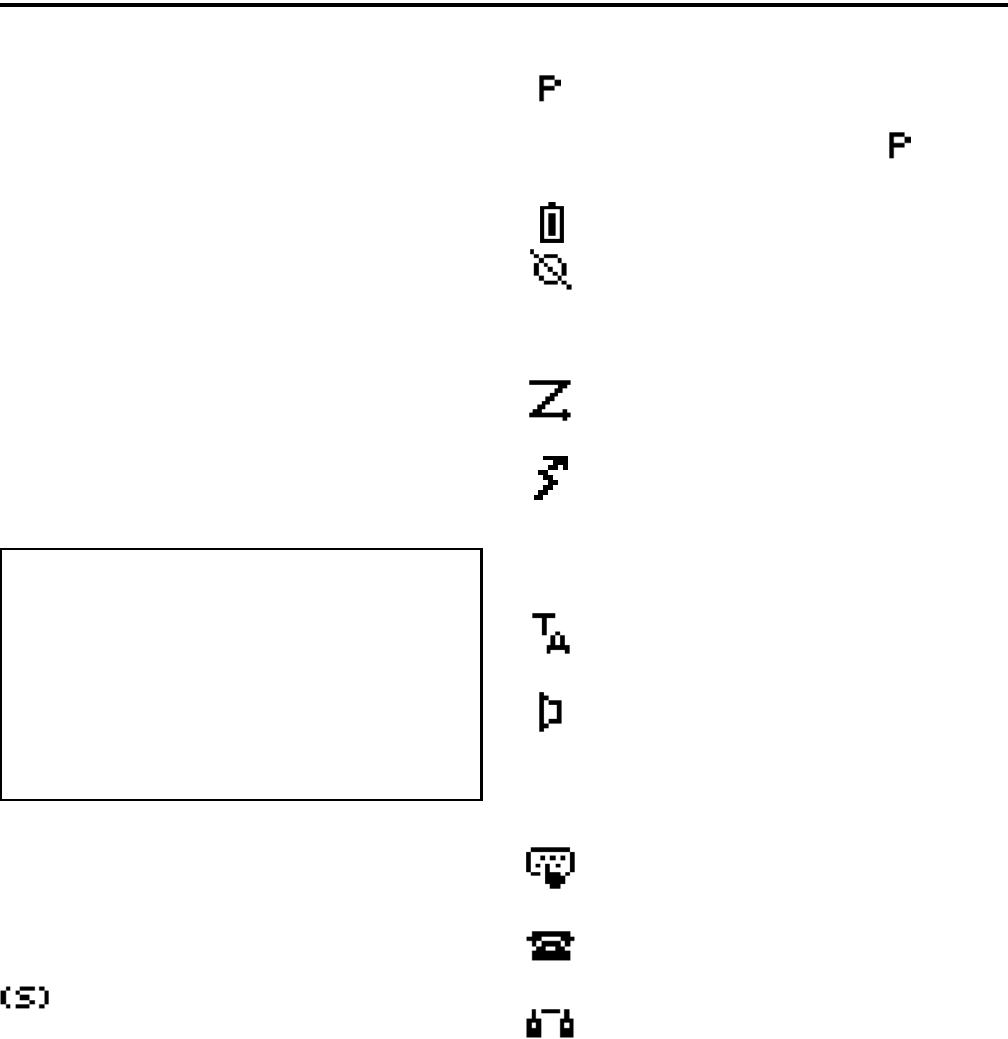
2.4 DISPLAY
Figure 2-4 Graphical Display
The front panel display is shown above. Icons are
typically shown in the upper part of the display and
text messages in the lower part. The icons are as
follows:
- When the scan or the scan list edit mode is
enabled, indicates that the displayed channel is in the
scan list and scanned (see Section 4.8).
- When the scan or the scan list edit mode is
enabled, indicates that the displayed channel is a
priority channel. If dual priority is used, indicates
that it is a second priority channel.
- Low battery indication (see Section 3.4).
- Voice encryption is enabled or an encrypted
call is being received. This indication flashes when an
encrypted call is received on a digital channel (see
Section 10.2.7).
- Priority or radio wide scanning is enabled (see
Section 4.8).
- In the surveillance mode only, indicates that
the transmitter is keyed (see Section 4.7). This icon is
displayed in place of the preceding scan mode icon
when applicable. They do not conflict because the
scan icon is not displayed in the transmit mode.
- Repeater talk-around is enabled (see
Section 5.8).
- The Monitor mode is enabled by the Monitor
option switch or menu parameter (see Section 5.3).
The radio can also be programmed so this icon is
displayed when the Normal mode is selected by the
Normal/Selective function (see Section 5.5.2).*
- Keypad programming or another mode is
enabled which allows the user to edit radio parameters.
- An interconnect (telephone) call is in progress
(see Section 6.6).
- A Project 25 or SMARTNET/SmartZone
private (unit-to-unit) call is in progress.
2

13
GENERAL OPERATION
SECTION 3 GENERAL OPERATION
3.1 TURNING POWER ON AND SETTING
VOLUME
3.1.1 POWER UP
Power is turned on and off by the top panel On-
Off/Volume switch. When power is initially turned on,
the following events occur:
•The software version number is displayed.
•A self test is performed.
•The currently selected zone is displayed.
•If a conventional P25 channel is selected, the
Individual ID of the radio is displayed.
•If a SMARTNET/SmartZone or P25 Trunked
channel is selected, the Unit ID of the radio is
displayed.
•A tone sounds (if tones are enabled)
•The selected channel alias is displayed continuously
when power-up is complete.
Programming determines if the radio powers up
on the last selected zone or the pre-programmed home
zone. Refer to Section 3.3 for information on the
channel that is selected. The minimum volume level
may be set by programming. This can prevent missed
messages resulting from inadvertently turning the
volume to an inaudible level.
3.1.2 STANDARD AND SOFT POWER DOWN
To turn power off, rotate the On-Off/Volume
control counterclockwise until a click occurs. Power
may remain on for an instant after turn-off occurs.
A soft power down feature can be programmed to
prevent radio power from being turned off by acciden-
tally turning the on-off/volume control. Any side
button can be programmed for this function in addition
to its normal function. Then for power to turn off, this
button must be pressed during or after power is turned
off in the normal manner using the knob (there is no
time out).
3.1.3 SETTING VOLUME LEVEL
The volume level is adjusted by the top panel
volume control knob or by option buttons programmed
for the Up/Down volume function. When the buttons
are used, the volume control function of the knob is
disabled (it is still used to switch power). Volume
buttons may be used instead of the knob, for example,
if accidental turning of the volume knob is a problem.
When the volume control buttons are used, the
number of steps (ticks) required to change the volume
from the minimum level to maximum level is
programmable for 1-50. For example, if “20” is
programmed, there are 20 adjustment steps from
minimum to maximum volume. Only one volume
control button can be programmed if desired and
wrap-around then occurs after the maximum or
minimum level is selected.
The radio can also be programmed so that volume
control is also be disabled by the Keypad Lock feature.
Refer to Section 3.6 for more information.
The relative volume level can be determined by
the position of the index on the volume knob or by a
reference signal as follows:
•If a key press tone is enabled, a short tone sounds
when a key is pressed.
•If a conventional channel is selected and the
Monitor option switch or menu parameter is
programmed, pressing that switch unsquelches the
receiver and either voice or background noise is
heard (see Section 5.3). If a SMARTNET/Smart-
Zone or P25 Trunked channel is selected, the
receiver cannot be manually unsquelched.
3.2 POWER-UP PASSWORD
3.2.1 GENERAL
The power-up password feature prevents unau-
thorized use of the radio by locking the keypad on
power up until the proper password is entered. This
feature is enabled or disabled by programming.
When it is enabled, “ENTER PSWD” is briefly
displayed when power is turned on. The eight-digit

GENERAL OPERATION
14
numeric password must be then be entered as follows.
If an incorrect password is entered, “INCORRECT” is
displayed and it must be re-entered.
DTMF Keypad Models - Enter the password using
the 1-8 keys and then press the Enter (F2) key when
finished. If a mistake is made, the last digit can be
erased by pressing the F1 (Clear) key.
Limited Keypad Models - Select the proper number
for each position by pressing the Up/Down switch.
When the proper number for a position is displayed,
select it and move on to the next position by pressing
the F2 (Enter) key. If the password is less than eight
digits, press F2 twice after the last digit.
3.2.2 PASSWORD FEATURES
An enhanced password scheme allows up to four
power-on (user) passwords, download and upload
passwords, and a master password to be programmed.
The current User password can be changed if the
“Set User Password” option switch or menu param-
eter is programmed. Selecting this function displays
prompts for entering and confirming a new password.
It is recommended that a number key not be used for
this function because the password mode is exited if
that key is pressed to enter a number. Refer to Section
9 for more information on passwords.
3.3 ZONE AND CHANNEL SELECT
The selected zone and channel are selected and
displayed as follows. For more information on zones
and channels, refer to Section 3.9.5.
Zone Select
The front panel Up/Down switch briefly displays
and changes the alias of the current zone. When not in
special modes such as the menu mode, pressing either
the top or bottom part of this switch once displays the
alias of the current zone. Then quickly pressing it
again changes the selected zone up or down. The
rotary A/B/C switch on the top panel can also be
programmed for zone select. The “A” position then
selects Zone 1, “B” Zone 2, and “C” Zone 3 (if appli-
cable).
After the highest programmed zone is displayed,
wrap-around to the lowest programmed zone occurs
and vice versa. The selected zone is also displayed
briefly on power up. If the selected zone alias needs to
be displayed continuously, it must be programmed as
part of the channel alias.
Channel Select
Channels are selected by the rotary 16-position
switch on the top panel. The alias (identification) for
the selected channel/group is displayed continuously
during normal operation.
When an unprogrammed channel is selected,
“UNPROGRAMD” is displayed and a tone sounds (if
tones are enabled). When conventional channels are
selected and the Display Information option key or
menu parameter is programmed, either the channel
frequency or alias can be displayed (see Section 5.9).
The channel selector knob can also be disabled by
programming. Channels must then be directly selected
as described next (if applicable). It may be desirable to
disable the channel select knob when direct selection
is used in order to prevent confusion since the channel
knob then may not indicate the selected channel.
The radio can also be programmed so that the
channel select control is also be disabled by the
Keypad Lock feature (Section 3.6) similar to the
volume control described in Section 3.1.3.
Direct Zone/Channel Selection
The direct Channel Select feature is available if
the Channel Select option switch or menu parameter is
programmed. This feature allows channels to be
directly selected using the DTMF keypad numeric
keys (DTMF models only) or Up/Down switch (all
models).
For direct selection purposes, channels are
numbered sequentially starting with the lowest zone.
Each zone can be programmed with up to 16 channels,
so Zone 1 channels are numbered 1-16, Zone 2 chan-
nels 17-32, and so on as shown below. For example,
Zone 1/Channel 16 is selected by Channel 16, and
Zone 2/Channel 16 is selected by Channel 32.
GENERAL OPERATION
15
Proceed as follows to select channels using this
mode:
1. Enable the direct Channel Select mode by pressing
the Channel Select option switch or selecting the
“Chan Selct” menu parameter. The alias and
sequential number of the current channel are
alternately displayed.
2. Select the desired channel using the Up/Down keys
or directly enter it using the 0-9 keys (if available).
If using the 0-9 keys, the radio attempts to display
the entered number after the 3rd digit is entered or
approximately 2 seconds after the last key is
pressed.
3. To exit the this mode and select the entered channel,
press the Channel Select switch again or the F2 key.
To exit without changing the channel, press the F1
key. This mode is also exited automatically without
changing the channel after approximately 1 minute
of no activity.
NOTE: The Channel Select function should probably
not be assigned to a number key because pressing that
key to select a channel then exits the select mode.
Other features of this mode are as follows:
•When using the Up/Down keys, wrap-around to the
lowest zone/channel occurs after the last channel in
the highest programmed zone is displayed and vice
versa. For example, if Zone 1/Channel 5 is the
highest programmed channel, wrap-around occurs
after Zone 1/Channel 16 is displayed.
•When an unprogrammed channel is displayed, the
sequential channel number and “Unprogramd” are
alternately displayed.
•If an invalid channel number is entered using the
0-9 keys, or the F2 or Channel Select option switch
is pressed with “Unprogrammed” displayed, an
error tones sounds, “Invalid” is briefly displayed,
and the displayed channel does not change.
•The rotary Channel Select switch may not correctly
indicate the selected channel after direct channel
selection is used. However, if this switch is enabled
and rotated, it selects the channel it is indicating. For
example, if the switch index is pointing to channel 3
and channel 15 of the current zone is being
displayed, rotating it to channel 4 selects channel 4
of the current zone.
•If the rotary Channel Select switch is enabled, the
radio always powers up on the channel it is
selecting.
If it is disabled, the radio can be programmed to
power-up on the last selected or home channel
number of the last selected or home zone. With the
“Last Zone”/“Home Channel” configuration, the
programmed home channel number of the last active
zone is selected. If it is not programmed, “Unpro-
grammd” is displayed. With earlier models, the last
selected channel is displayed when powering up on
the last selected zone, and channel 1 is displayed
when powering up on the home zone.
3.4 LOW BATTERY INDICATION
3.4.1 GENERAL
NOTE: If the radio contains encryption keys and is not
programmed for infinite key retention, be sure to reat-
tach a battery within approximately 30 seconds to
prevent the loss of these keys (see following).
A low-battery condition is indicated by the
icon in the display. The battery should be recharged or
replaced as soon after this indication appears. Once
this indication appears, it stays on until power is
cycled.
Seq. Ch. No. Zone Channel
111
16 16
17 2 1
32 16
33 3 1

GENERAL OPERATION
16
The following additional low battery indications
and conditions may be enabled by programming:
•A chirp sounds once a minute in the receive standby
and transmit modes.
•A chirp sounds each time the PTT switch is pressed.
•The top panel LED indicator flashes red every 30
seconds in the receive mode.
•Low power is selected when transmitting.
As indicated in the preceding note, the radio may
need to be connected to a constant power source to
preserve the encryption keys in memory. This is
required if “infinite key retention” is not programmed.
To allow the battery to be changed without losing the
keys with this feature disabled, storage capacitors
maintain the supply voltage to memory for approxi-
mately 30 seconds without a battery attached. There-
fore, be sure to reattach a battery within that time. Refer
to Section 8.1.6 for more information on encryption
keys.
There is a battery saver feature that can be
enabled by programming. This feature functions on
trunked channels only, and it automatically selects low
transmit power when the receive signal strength
(RSSI) indicates that the site is nearby.
3.4.2 BATTERY CHARGING
NOTE: When a battery is charged while attached to
the radio, make sure radio power is off (see following).
The battery can be charged separately or while
attached to the radio. When it is charged while
attached to the radio, radio power should be turned off.
If it is not, the battery begins slowly discharging when
the charger enters the trickle charge mode. This mode
is indicated by a green Ready indication, and it is
entered automatically when the battery is nearly fully
charged. Gradual discharging occurs in the trickle
mode because the charge current of approximately 50
mA is less than the radio standby current of approxi-
mately 200 mA.
CAUTION: Do not transmit in close proximity to the
charger base (see following).
Do not expose the charger base to high level RF
signals while a battery is being charged because this
may cause a charger fuse to blow (especially in the
UHF range). Radios programmed for SMARTNET/
SmartZone operation, for example, may affiliate while
in the charger which causes them to automatically key.
Therefore, do not leave radio power on while charging
as described above.
3.5 BACKLIGHT
The backlight for the display and option keys can
be programmed to automatically turn on when any key
is pressed. It then automatically turns off after a
programmed delay of 0-7.5 seconds so that battery
drain is minimized. If the Backlight option switch or
menu parameter is programmed, the user can manually
turn the backlight on and off (it then stays on). If the
Surveillance mode is programmed, the backlight is
disabled (see Section 4.7). The radio can be
programmed so that the backlight turns on in the
keypad lock mode when a key is pressed (see next
section).
3.6 KEYPAD LOCK
The Keypad Lock feature temporarily disables
the front panel keys to prevent keys from being acci-
dentally pressed. This feature is available if the
Keypad Lock option switch is programmed. To lock
the keypad, simply press the Keypad Lock option
switch. Then to unlock the keypad again, press and
hold this switch until a tone sounds (approximately 1
second).
Permanent Keypad Lockout can also be
programmed. The keypad is then permanently disabled
and cannot be enabled by the user. Additional informa-
tion on this feature is as follows:
•A global “Front Keypad Lockout Only” function
can be selected by programming. The front panel
keys but not the side panel option keys are then
disabled by the preceding Keypad Lock and Perma-
nent Lock functions. If this function is not selected,
both the front and side panel keys are disabled. The
PTT switch is never disabled.
•The Channel Selector and Volume controls can be
programmed so that they are locked by the Keypad
Lock function.
•The “Channel Selector Enabled” function can be
programmed globally. If this is not selected, the

GENERAL OPERATION
17
channel selector is always disabled regardless of the
Permanent Lockout or Keypad Lock status. Chan-
nels can then be selected only by direct channel
select (see Section 3.3).
•The volume control is permanently disabled if a
Volume Up/Down option switch is programmed
regardless of the Permanent Lockout or Keypad
Lock status. Refer to Section 3.1.3 for more
information.
•There is the option to enable the backlight when a
key is pressed in the Keypad Lock mode. There is
also the option when programming conventional
channels to disable DTMF dialing.
3.7 SETTING SQUELCH
This radio does not have a squelch control. The
squelch level is preset during alignment. If the keypad
programming feature is available (see Section 5.18),
the squelch level can be changed by the user on each
conventional analog channel.
3.8 TRANSMIT DISABLE
Transmitting can be disabled on each conven-
tional, SMARTNET, SmartZone, and P25 Trunked
channel so that the channel is monitor-only. When
transmitting is attempted on a receive-only channel,
“Rx Only” is displayed and an error tone sounds.
3.9 RADIO OPERATING MODES
3.9.1 GENERAL
Each selectable channel can be programmed for
the conventional (analog or APCO Project 25 digital),
SMARTNET/SmartZone, or APCO Project 25 digital
trunked operating mode. For example, Zone 1/Channel
1 could be a conventional channel, Zone 1/Channel 2 a
SMARTNET channel, and so on. More information on
these modes follows.
3.9.2 CONVENTIONAL MODE
This is a non-trunked operating mode which
accesses independent radio channels. There is no auto-
matic access to several channels. Selecting a conven-
tional channel selects a transmit and receive frequency
and other channel parameters such as squelch control
coding.
Conventional channels can be either standard
(analog) or Project 25 (digital). With digital operation,
the DSP (Digital Signal Processor) converts the audio
signal to digital data which is sent over the air as
complex tones. Another difference is that analog chan-
nels use Call Guard (CTCSS/DCS) squelch control
and Project 25 channels use a NAC (Network Access
Code) and talk group ID codes.
With Project 25 operation, a NAC is transmitted
and it must match the NAC programmed in the base
equipment and the radio(s) being called for communi-
cation to occur. In addition, to receive standard group
calls, the receiving radio must be programmed to detect
the transmitted talk group ID code.
With conventional operation, a busy channel
condition is detected automatically if the busy channel
lockout (transmit disable on busy) feature is
programmed. Otherwise, it must be detected manually.
An out-of-range condition is not indicated by special
tones or messages as with SMARTNET operation
because there is no initial data exchange with the
repeater that allows this condition to be detected.
Operating features unique to conventional channels
are described in Section 5.
3.9.3 SMARTNET/SMARTZONE MODE
This is a trunked operating mode in which auto-
matic access is provided to several RF channels. ID
codes are used to select what radios are being called
and what calls are received. Monitoring is performed
automatically and special messages and tones indicate
busy and out-of-range conditions.
SMARTNET and SmartZone operation and
programming is very similar. Basically, SMARTNET
operation is limited to a single repeater site and Smart-
Zone operation allows automatic roaming between
sites. Enhanced SMARTNET/SmartZone features
include roaming (SmartZone only), telephone, private,
and emergency calls, Call Alert™, and messaging.
Either analog or digital signaling may be used (digital
is optional).

GENERAL OPERATION
18
When a SMARTNET or SmartZone channel is
selected or the radio is powered up on one of those
channels, it searches for a control channel. Once a
control channel is found, the alias (name) of the
selected channel is displayed and the radio attempts to
register on the radio system. If a control channel could
not be found (because of an out of range condition or
the system ID is not correct, for example), “NO SYS”
(early units) or “Out Rnge” (later units) is displayed
and the radio continues to search for a control channel.
The control channel transmits and receives
system information to and from all radios registered on
the system. Therefore, once a control channel is found,
it is continuously monitored for incoming call infor-
mation and is used to make call requests. The radio
automatically changes to a traffic channel to place and
receive calls and then returns to the control channel
when the call is complete. Operating features unique
to SMARTNET/SmartZone channels are described in
Section 6.
3.9.4 P25 TRUNKED MODE
The P25 Trunked operating features are very
similar to the SmartZone type just described. Since
SmartZone features are also similar to SMARTNET
features, all three modes are described in the
Section 6. Some differences between the P25 Trunking
and SmartZone modes are as follows:
•Digital signaling is always used with P25 calls.
Either analog or digital signaling may be used for
SmartZone calls.
•Calls made to a specific radio in the P25 mode are
called Unit Calls. In the SMARTNET/SmartZone
mode they are called Private Calls.
•Messaging is not available with P25 calls.
•The P25 control channel data rate is 9600 baud and
the digital voice data rate is also 9600 baud. With
SmartZone operation, the control channel data rate
is 3600 baud (both digital and analog calls) and the
narrowband digital voice data rate is 9600 baud.
•The P25 mode uses a system ID, Wide Area
Communications Network (WACN) ID, and RF
Subsystem ID (RFSS). The SmartZone mode does
not use the WACN and RFSS IDs.
•P25 Unit IDs can be 1-16,777,215 (000001-FFFFFF
hex) and SmartZone Unit IDs can be 1-65,535
(0001-FFFF hex).
3.9.5 SYSTEMS, CHANNELS, AND ZONES
A zone and channel are selected to place and
receive calls. The following describes the relationship
between systems, channels, and zones.
Systems
A system is a collection of channels or talk
groups belonging to the same repeater site. It defines
all the parameters and protocol information required to
access a site. Up to 16 systems of any type can be
programmed.
The maximum number of channels assignable to
a system is limited to 512. Channels may also be
limited by available memory space as described in the
following information.
Channels
A channel selects a radio (RF) channel or talk
group as follows:
Conventional Analog Mode - A channel selects a
specific radio channel, Call Guard (CTCSS/DCS)
squelch coding, and other parameters unique to that
channel.
Conventional Project 25 Mode - A channel selects a
specific radio channel, NAC squelch coding, talk
group ID, and other parameters unique to that channel.
SMARTNET/SmartZone and Trunked Project 25
Modes - A channel selects a specific talk group,
announcement group, emergency group, and other
parameters unique to that talk group.
A maximum of up to 512 channels can be
programmed with the preceding modes. These chan-
nels can belong to a single system or multiple systems.

GENERAL OPERATION
19
The maximum number is also limited by the available
memory. For example, since more memory is required
to program a SMARTNET system than a conventional
system, the total number of channels decreases as the
number of SMARTNET channels increases. The
programming software displays a bar graph which
shows the amount of available memory space that is
used by the current data.
Zones
A zone is a collection of up to 16 channels of any
type. For example, a zone could include 12 conven-
tional channels and 4 SMARTNET channels. One use
of zones may be to program the channels used for
operation in a different geographical areas. The
maximum number of zones is 32.

20
RADIO-WIDE FEATURES
SECTION 4 RADIO-WIDE FEATURES
4.1 OPTION SWITCHES
NOTE: For descriptions of the functions controlled by
these switches, refer to the section of this manual
referenced in the last column of Table 4-1.
Almost all the buttons on this radio are
programmable as follows:
•On the side panel, the three buttons above the PTT
switch (see Figure 2-3 on page 11).
•On the top panel, the rotary three-position switch
and the orange button (see Figure 2-2 on page 11).
•On the front panel, F1 and F2 unless the menu mode
is used (see next section), and F3 and F4.
•With DTMF keypad models, all 12 DTMF keys.
The functions that can be controlled by option
switches are shown in Table 4-1. Each option switch
can be programmed to control a different function in
each of the three operating modes. For example, F3
can control one function when a conventional channel
is selected, another when a SMARTNET/SmartZone
channel is selected, and still another when a Project 25
trunked channel is selected.
4.2 MENU MODE
NOTE: For descriptions of the functions controlled by
the menu mode parameters, refer to the section of this
manual referenced in the last column of Table 4-1.
Most functions that can be controlled by an
option switch can also be controlled by the menu
mode. The functions that can be controlled by the
menu mode are shown in Table 4-1. Functions can be
controlled by both an option switch and a menu
parameter if desired.
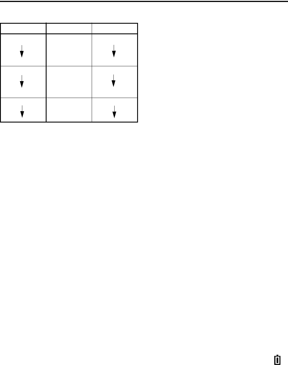
When the menu mode is used, the F1 and F2
switches become dedicated menu mode control
switches (see following illustration). The F1 switch is
Back/Clear, and the F2 switch is Menu Select/Enter. If
the menu mode is disabled, these switches can be
programmed for other functions.
Menu Mode Buttons
Only the enabled menu items which apply to the
selected channel type are displayed. For example, if a
conventional channel is selected, only the enabled
functions for conventional channels are displayed.
When in the menu mode, messages continue to be
received on the selected channel. However, the display
does not indicate who is calling. Pressing the PTT
switch exits the menu mode and keys the transmitter.
The menu mode operates as follows:
1. To select the menu mode, press the F2 key. Up to
three menu parameters are then displayed as shown
in the preceding illustration.
2. To scroll up or down through the menu parameter
list, press the Up/Down switch. The selected
parameter is indicated by a dark bar.
3. To display the available modes for a highlighted
parameter, press the F2 switch. The currently
selected mode is indicated by an asterisk.
4. Press the Up/Down switch to highlight the desired
mode. Then press the F2 key to select that mode.
5. To step back to the previous level or exit the menu
mode, press the F1 (Back) key.
4.3 TIME-OUT TIMER
The time-out timer disables the transmitter if it is
keyed continuously for longer than the programmed

RADIO-WIDE FEATURES
21
Table 4-1 Programmable Option Switch and Menu Mode Functions
Function Menu
Display
Available in Mode: See Descript.
in Section:
Conv. P25 Trk SMARTNET SmartZone
Alert tones On-Off TonesXXXX4.6
Backlight On-Off BacklightXXXX3.5
Call Alert Select Call AlertXXXX5.17.7, 6.7
Call Response Select Call Rsp X X X 6.5
Cancel Dynamic Regroup Cancel DR X X X 6.13
Change Keyset (OTAR)Chg KeysetXXXX10.6.3
Channel Select Chan SelctXXXX3.3
Clear/Secure Select SecurityXXXX10.3
Clone Select (menu only) Clone X 5.16
Configure (menu only)ConfigXXXXNot curr. used
Digital Talk Group Select Select TG X 5.17
Display Information Select Display X 5.9
Emergency Select EmergencyXXXX
5.10, 6.10
Erase Keys (menu only)Erase KeysXXXX10.2.6
High/Low Power SelectTx PowerXXXX4.5
Home Zone SelectHome ZoneXXXX4.4
Key Select Key Select X 10.2.5
Keypad Lock Select (Opt sw only) X X X X 3.6
Keypad Programming Select Keypad Prg X 5.18
Messaging Message X X X 5.17.8, 6.8
Monitor Mode Select Monitor X 5.3
Normal/Selective Select Squelch X 5.5
OTAR Rekey Request OTAR Rekey X 10.6.3
P25 Packet Data Data Modes X X 5.17.10
Phone Call Select PhoneXXXX5.17.6, 6.6
Priority Channel Select Priority X 5.11.3
Private Call Select Priv Call X X 6.5
Radio Wide Scan SelectRW ScanXXXX4.8
Repeater Talk-Around Select Talk Arnd X 5.8
RWS List Edit RWS EditXXXX4.9.2
Scan Mode Select ScanXXXX4.8
Scan List Edit SelectScan EditXXXX4.8
Scan List Select Scan SelctXXXX4.8
Set User Password Set PaswdXXXX 9
Squelch Select List Sqlch Code X 5.5
Single Tone Encoder Tone Encdr X 5.14
Site Lock Select Site Lock X X 6.14
Site Search Select Site Srch X X 6.14
Status Select StatusXXXX5.17.9, 6.9
Surveillance Mode SelectSurv ModeXXXX4.7
Tone Volume Edit Tone VolXXXX4.6
Unit Call Select Unit Call X X 5.17
Unprogrammed (not used)- XXXX -
Volume Down (Opt sw only)XXXX3.1.3
Volume Up (Opt sw only)XXXX3.1.3

RADIO-WIDE FEATURES
22
time. It can be programmed for 15 seconds to 3
minutes, 45 seconds or it can be disabled.
If the transmitter is keyed for longer than the
programmed time, the transmitter is disabled, a contin-
uous tone sounds, and “TX TIMEOUT” is displayed.
Five seconds before time-out occurs, a warning beep
sounds to indicate that time-out is approaching. The
timer and tone are reset by releasing the PTT switch.
A different time can be programmed for each
system, and the timer can be enabled or disabled on
each conventional channel. With conventional chan-
nels, a penalty time may also be programmed that
prevents transmissions for a certain time after the
transmitter is disabled (see Section 5.6).
One use of this feature is to prevent a channel
from being kept busy for an extended period by an
accidentally keyed transmitter. It can also prevent
possible transmitter damage caused by transmitting for
an excessively long period.
4.4 HOME ZONE/CHANNEL SELECT
If the Home Zone option switch or menu param-
eter is programmed, it selects the preprogrammed
home zone. The selected channel is displayed if the
channel switch is enabled, and the preprogrammed
home channel is selected if it is disabled.
Pressing and holding the Home Zone option
switch until a tone sounds makes the currently selected
zone the new Home zone. The radio is also
programmed so that either the home or last selected
zone is selected when power is turned on. Refer to
Section 3.3 for more information.
4.5 POWER OUTPUT SELECT
Each conventional channel and SMARTNET/
SmartZone and P25 Trunked system can be
programmed for high, low, or switchable power. If the
High/Low Power option switch or menu parameter is
programmed and selectable power is programmed on
the current channel or system, high and low trans-
mitter power can be selected. All models support high
and low power. The low power level is typically 1 watt
and the high power level the rated power output of the
radio (2.5 - 5 watts, depending on frequency band).
The new level is flashed in the display as either
“HI POWER” or “LOW POWER”. If selectable
power is not permitted on the current channel,
“FIXED LOW” or “FIXED HIGH” is flashed and no
change occurs. The selected power level for a channel
or system is permanent until it is manually changed
again. The low power mode may be automatically
selected during a low battery condition (see
Section 3.4).
4.6 ALERT TONE SELECT
The various alert tones that sound are described
in Section 7.1. These tones can be turned on and off if
the Alert Tone option switch or Tones menu parameter
is programmed. When all tones are off, “TONE OFF”
is momentarily displayed, and when all tones are on,
“TONE ON” is momentarily displayed. If this switch
or menu parameter is not programmed, tones are fixed
in the on or off mode by programming. If the Surveil-
lance mode is programmed (see following), tones are
totally disabled.
The Alert Tone volume can be adjusted relative to
the volume control setting. This is done by program-
ming and also by the user if the Tone Volume Adjust
option button or menu parameter is programmed.
Relative levels of –170 to +170 can be set with “0” the
default setting. A minus value decreases the tone
volume and a plus value increases it. The user adjusted
level permanently overrides the programmed level if
applicable.
4.7 SURVEILLANCE MODE
The Surveillance mode totally disables the back-
light, all alert tones, and front panel LED indicator in
all operating modes. The radio can be fixed in this
mode by programming or it can be turned on and off
by the user if the Surveillance Mode option button or
menu parameter is programmed. The user selected
mode permanently overrides the programmed mode if
applicable. To provide a transmit indication when the
front panel LED is disabled, the icon is displayed
(see Section 2.4). This icon is displayed only in the
surveillance mode.

RADIO-WIDE FEATURES
23
4.8 SCANNING
4.8.1 INTRODUCTION
Scanning monitors the channels in the scan list
for messages that the radio is programmed to receive.
When a message is detected, scanning stops and the
message is received. Shortly after the message is
complete, scanning resumes (unless it has been
disabled). When a call is received in the scan mode,
the alias of the channel on which a call is received
(and any other display parameters that may be
programmed) are displayed until scanning resumes.
The selected channel alias is then displayed if
applicable.
There are two basic scan modes available:
Priority (Standard) and Radio Wide. The operation of
the priority type is unique to the type of channel
selected, and the operation of Radio Wide type is the
same regardless of the type of channel selected. Only
one type can be enabled at a time. For example, if
priority scanning is enabled and radio wide scanning is
selected, priority scanning is automatically disabled
and vice versa. More information on these types of
scanning follows.
4.8.2 PRIORITY SCANNING
Priority scanning (also referred to as standard
scan) monitors only channels that are the same type as
that currently selected. For example, if a conventional
channel is selected, only conventional channels are
scanned and likewise for SMARTNET/SmartZone and
Project 25 Trunked channels.
More information on how priority scanning oper-
ates in the Conventional Mode is located in Section
5.11, and for the other modes in Section 6.12. Priority
scanning is turned on and off by the Scan option
switch or menu parameter as follows. If this switch or
menu parameter is not programmed, Priority scanning
is not available.
•Enable scanning using the Scan option switch or
menu parameter. Scanning is enabled when “Scan
On” is briefly displayed and the icon is
indicated.
•To turn scanning off, press the Scan option switch
again or select “Off” in the scan menu. Scanning is
disabled when “Scan Off” is briefly displayed and
the icon is no longer indicated.
•If the zone or channel is changed while scanning is
selected, scanning continues on the same or a
different scan list (see Section 4.9.1).
NOTE: Each SMARTNET/SmartZone and P25 trunked
channel can be programmed so that scanning is auto-
matically enabled when the channel is selected.
4.8.3 RADIO WIDE SCANNING
NOTE: Use radio wide scanning only if two different
channel types need to be scanned at the same time
such as conventional and SMARTNET/SmartZone.
Otherwise, use the more efficient priority scanning
because there is less chance of missed calls.
Radio wide scanning monitors the channels in the
preprogrammed radio-wide scan list. This scan list can
include up to 16 channels of any type and assigned to
any zone (see Section 4.9.2). Radio wide scanning is
turned on and off by the Radio Wide Scan option
switch or menu parameter as follows. If this switch or
menu parameter is not programmed, radio wide scan-
ning is not available.
•Enable Radio Wide Scanning using the Radio Wide
Scan option switch or menu parameter. Radio wide
scanning is enabled when “RW Scn On” is briefly
displayed and the icon is indicated.
•To turn radio wide scanning off, press the Radio
Wide Scan option switch again or select “Off” in the
menu. Scanning is disabled when “RW Scn Off” is
briefly displayed and the icon is no longer
indicated.
•If the zone or channel is changed while radio wide
scanning, scanning continues normally.
4.8.4 SCAN HOLD TIME
When a message is received or transmitted while
scanning, there is a delay before scanning resumes.
The delay after receiving a call prevents another
message from being received before a response can be
made. The delay after transmitting a call ensures that a
response is heard instead of another message occurring
on some other channel.

RADIO-WIDE FEATURES
24
Separate delay times are programmable for Radio
Wide and Priority scanning. With radio wide and
conventional priority scanning, delays of 0-7.5
seconds are programmable in 0.5-second steps. With
SMARTNET/SmartZone and P25 Trunked priority
scanning, a scan delay of 2-10 seconds can be
programmed in 0.5-second steps.
4.8.5 TRANSMITTING IN THE SCAN MODE
Priority Scan Mode
When the transmitter is keyed while scanning is
enabled, the transmission may occur on various
channels as follows.
Conventional Operation - Transmissions can be
programmed to always occur on the priority,
selected, or receive channel (if applicable). Refer to
Section 5.11 for more information.
SMARTNET/SmartZone/P25 Trunked
Operation - If scanning is halted to receive a
message, programming determines if transmis-
sions occur on the selected or active channel.
Transmissions at other times occur on the selected
channel.
Radio Wide Scan Mode
The radio can be programmed to transmit on the
selected or active channel similar to SMARTNET/
SmartZone and P25 trunked operation just described.
4.8.6 NUISANCE CHANNEL ADD/DELETE
With priority scanning, channels can be tempo-
rarily deleted from the scan list, for example, if
messages become annoying. This feature is not avail-
able with radio wide scanning. Channels can also be
permanently added or deleted from a scan list as
described in the next sections. Proceed as follows to
temporarily delete a nuisance channel:
NOTE: The selected channel and also priority chan-
nels cannot be deleted from the scan list.
1. While receiving a message on the channel to be
deleted, press and hold the Scan option switch until
a tone sounds (about 1 second).
2. The channel is then deleted and scanning of the
remaining channels in the scan list resumes.
3. Deleted channels are added back into the scan list if
any of the following occur:
•Scanning is turned off and then on again using the
Scan option switch or menu parameter.
•Radio power is turned off and then on again.
•The selected channel is changed.
4.9 SCAN LISTS
4.9.1 PRIORITY SCAN LISTS
General
NOTE: The selected channel is always scanned.
A scan list is simply the channels that are scanned
when scanning is enabled. With all operating modes,
as many priority scan lists as are required can usually
be programmed (up to 256). The only limitation is the
available memory. Each scan list can include up to 512
channels/talk groups. More information on selecting
and editing priority scan lists follows.
Determining Channels in Priority Scan List
The channels in conventional priority scan lists
are indicated by selecting the scan mode as follows.
Channels in SMARTNET/SmartZone/P25 Trunked
priority scan lists are indicated only when editing a
scan list (see “Editing a Priority Scan List” which
follows).
1. Enable priority scanning using the Scan switch or
menu parameter. Also select the scan list if appli-
cable as described in the following “Selecting a
Priority Scan List” description.
2. Select the desired zone and then scroll through the
channels by rotating the channel switch. When the
displayed channel is in the scan list (scanned
normally), the icon is displayed.

RADIO-WIDE FEATURES
25
Selecting a Priority Scan List
NOTE: Only priority scan lists are selectable.
Conventional Channels - Conventional systems are
programmed with a default scan list that is normally
selected by all channels in that system. However, there
is a programmable option to slave a particular conven-
tional scan list to a zone. This then becomes the
default list for all conventional channels in that zone
(it overrides the system programming). This slave
feature is programmed on the Edit Zone screen.
If the Scan (List) Select option switch or menu param-
eter is programmed, the default list selected by all
conventional channels (even those belonging to slaved
zones) is temporarily changed. The preceding default
scan lists are automatically reselected whenever radio
power is cycled.
SMARTNET/SmartZone and Project 25 Trunked
Channels - Each channel (talk group) can be
programmed so that one of the programmed lists is
selected or scanning is disabled (No List). In addition,
channels can be programmed so that scanning is auto-
matically enabled (Auto Scan) when they are selected.
If the Scan (List) Select option switch or menu param-
eter is programmed, the list that is selected by all talk
and announcement groups in the current system can be
temporarily changed by the user as follows. “No List”
(scanning disabled) or “Programmed” (default list) can
also be selected if desired. The programmed default
scan list is automatically reselected on power up.
To change the currently selected scan list (all
channel types), proceed as follows:
1. With scanning disabled ( icon not displayed),
press the Scan List option switch or select the Scan
Selct menu parameter.
2. The currently selected list is displayed as “List x”,
where “x” is the currently selected list. To exit
without changing the selected list, simply press the
Scan List option switch again or the F1 key.
3. To select another list, press the Up/Down switch.
When the desired list is displayed, select it and exit
this mode by pressing the Scan List option switch
again or the F1 or F2 key.
Editing a Priority Scan List
If the Scan Edit option switch or menu parameter
is programmed, conventional, SMARTNET/
SmartZone, and P25 Trunked priority (standard) scan
lists can be user programmed. Changes are permanent
(cycling power does not reselect a default condition).
Proceed as follows:
1. Make sure that both priority and radio wide scan-
ning are off ( icon not displayed). Select a
conventional or SMARTNET/SmartZone/P25
Trunked channel corresponding to the scan list
being programmed.
2. Select the scan edit mode using the Scan Edit option
switch or menu parameter. This mode is indicated
by in the display.
3. If applicable, select the list to be edited by pressing
the Up/Down switch. Select the desired list by
pressing the F2 key. The selected list is indicated as
“LIST x”. If user programming is disabled on a list,
(conventional only) “NO EDIT” is momentarily
displayed and it cannot be edited.
4. Select the channel you want to add or delete by
pressing the Up/Down switch. After the last channel
in the current zone is displayed, the first valid
channel in the next zone is displayed and vice versa.
Lists are limited to 512. If an attempt is made to add
more than 512, “LIST FULL” is displayed and a
channel must be deleted before another can be
added.
NOTE: Priority channels can be deleted.
5. If the selected channel is in the scan list (scanned),
the icon is displayed. To change the status of
the displayed channel, press the F2 (Enter) switch.
With conventional channels only, if the selected
scan list is programmed with fixed priority
channel(s), the next press of F2 makes the current
channel the priority channel indicated by . If
dual priority channels are used, pressing F2 again
makes it the second priority channel indicated by
RADIO-WIDE FEATURES
26
. Then pressing F2 again takes the channel out
of the scan list. Refer to Sections 5.11.3 and 6.12.2
for more information on priority channel sampling.
6. To exit this mode and save the changes, press the F1
(Exit) key or the Scan Edit option switch again.
7.
4.9.2 RADIO WIDE SCAN LISTS
General
With radio wide scanning, there is only one scan
list available regardless of the type of channel selected.
This list is user programmable in later units, and can
contain up to 16 channels of any type. For example, it
could include six conventional channels and ten
SMARTNET/SmartZone channels. More information
on selecting and editing radio wide scan lists follows.
Determining Channels in Radio Wide Scan List
The channels in radio wide scan lists are deter-
mined by selecting the scan list edit mode (see
“Editing Radio Wide Scan List” which follows).
When the displayed channel is in the radio wide
scan list (scanned normally), the icon is
displayed.
Editing a Radio Wide Scan List
If the RWS Edit option switch or menu param-
eter is programmed, the radio wide scan list can be
edited. Changes are permanent (cycling power does
not reselect a default condition). Proceed as follows:
1. Make sure that both priority and radio wide scan-
ning are off ( icon not displayed). Select the
scan edit mode using the RWS Edit option switch or
menu parameter. This mode is indicated by in
the display.
2. Select the channel you want to add or delete by
pressing the Up/Down switch. After the last channel
in the current zone is displayed, the first valid
channel in the next zone is displayed and vice versa.
Lists are limited to 16 channels. If an attempt is
made to add more than 16, “LIST FULL” is
displayed and a channel must be deleted before
another can be added.
3. If the selected channel is in the scan list (scanned),
the icon is displayed. To change the status of
the displayed channel, press the F2 (Enter) switch.
4. To exit this mode and save the changes, press the F1
(Exit) key or the RWS Edit option switch again.
2
27
CONVENTIONAL MODE FEATURES
SECTION 5 CONVENTIONAL MODE FEATURES
5.1 INTRODUCTION
An overview of the conventional operating mode
is located in Section 3.9.2. The following information
describes the features unique to analog and digital
(Project 25) conventional operation. Refer to the
preceding “Radio Wide Features” section (4) for infor-
mation on features common to all operating modes.
5.2 MONITORING BEFORE TRANSMITTING
With conventional operation, you may need to
manually monitor the channel before transmitting to
make sure that it is not be used by someone else. If
you were to transmit while someone else was using the
channel, you would probably disrupt their conversa-
tion. With SMARTNET/SmartZone and P25 Trunked
operation, monitoring is performed automatically.
Monitor conventional channels automatically or
manually as follows:
Automatic Channel Monitoring
If the selected channel is programmed for Busy
Channel Lockout (also called Transmit Disable On
Busy), monitoring is performed automatically. Refer
to Section 5.4 for more information on this feature.
Manual Channel Monitoring
The automatic monitoring just described may
occasionally disable the transmitter when the channel
is not in use, such as if the repeater has extended hang
time. In this case, you may not want to use it and the
channel must then be monitored manually as follows:
Busy Indicator - With scanning disabled, note if the
multi-function indicator on the front panel is steady
green. If it is not, the channel is not being used and a
call can be transmitted. It it is green, a carrier is being
detected, so the channel may be busy (see following).
Monitor Mode - There may be times when a busy
condition is indicated even though no one is using the
channel. Monitoring should then be performed by
disabling Call Guard squelch (or group ID detect on
Project 25 channels). This is usually done by selecting
the Monitor Mode (see following) or by the Normal/
Selective option switch or menu parameter (see Section
5.5.5).
5.3 MONITOR MODE
The monitor mode unsquelches the receiver and
monitors the channel even if a carrier is not detected.
Other features of this mode are as follows:
•Call Guard (CTCSS/DCS) squelch is disabled on
analog channels and NAC and group ID detect are
disabled on P25 (conventional) channels.
•Busy Channel Lockout is overridden (see next
section)
•Scanning temporarily halts
The Monitor Mode operates as follows:
1. To monitor the transmit frequency for activity
before transmitting, briefly press the Monitor option
switch or select the Monitor menu “Tx Channel”
parameter. The icon is then displayed to indicate
the monitor mode and the receiver unsquelches.
2. To monitor the receive frequency instead, press and
hold the Monitor option switch until a tone sounds
or approximately 2 seconds, or select the Monitor
menu “Sqlch Ovrd” parameter. This can be used, for
example, to improve reception if intermittent
squelching is making a weak message difficult to
understand.
3. To disable the monitor mode and return to normal
operation, press the Monitor option switch again of
select the Monitor menu “Off” parameter.
The Normal/Selective function disables Call
Guard squelch and P25 group ID detect but not
scanning and P25 NAC detect (see Section 5.5.5).
5.4 BUSY CHANNEL LOCKOUT
The Busy Channel Lockout feature (also called
Transmit Disable on Busy) automatically disables the
transmitter if the channel is busy when the PTT switch
is pressed. When the transmitter is disabled by this

CONVENTIONAL MODE FEATURES
28
feature, “BUSY” is displayed, a busy tone sounds, and
the transmitter is disabled.
The Busy Channel Lockout feature can be
programmed to operate as follows. Each conventional
channel can be programmed differently.
Off - Busy channel lockout is disabled and the trans-
mitter keys even if the channel is busy.
Noise - If a carrier is detected on the channel, the
transmitter is disabled when the PTT switch is pressed.
Tone (NAC) - If an incorrect Call Guard (CTCSS/
DCS) or NAC code (see Section 5.17) is detected, the
transmitter is disabled when the PTT switch is pressed.
An incorrect code is any code other than the one
programmed for the current channel.
If Busy Channel Override is permitted by
programming, it is possible to transmit even when the
transmitter is disabled by this feature. Simply release
the PTT switch and then quickly press it again.
5.5 CALL GUARD SQUELCH
5.5.1 INTRODUCTION
Tone or digital Call Guard squelch (also called
CTCSS/DCS signaling) can be programmed on each
conventional analog transmit and receive channel in
any order desired. The reverse burst and turn-off code
are always transmitted and also detected on channels
programmed with Call Guard squelch.
The Call Guard squelch feature eliminates
distracting messages intended for others using the
channel. This is done by using a subaudible tone or
digital code to control the squelch. This tone or code is
unique to a user or a group on that channel. This tone
or code is transmitted with the voice signal but is not
heard because it is in the subaudible range and is atten-
uated by a filter. Call Guard squelch must be used in
both the transmitting and receiving radio to be func-
tional.
5.5.2 CALL GUARD SQUELCH ENABLE/
DISABLE
The Normal/Selective option switch or menu
parameter (if programmed) can be used to disable
receive Call Guard squelch on analog channels or
group ID code detection on P25 channels. When selec-
tive squelch is disabled, “Sq Normal” is flashed in the
display, and when it is enabled, “Sq Select” is flashed.
When “Normal” is selected, the receiver
unsquelches only if a carrier is detected. Scanning and
Project 25 NAC detection are not disabled with this
mode selected. The selected mode is in effect until it is
manually changed again. Selecting another channel or
cycling power does not reselect a default condition.
There is a programmable option to display the monitor
icon when the “Normal” mode is selected.
5.5.3 TONE CALL GUARD SQUELCH
Tone-type Call Guard squelch utilizes subaudible
CTCSS tones from 67-254.1 Hz. Although there are 42
tones assigned, those above 33 (210.7 Hz) are normally
not used because of their close proximity to the voice
band which starts at 300 Hz. In addition, tones 11 (97.4
Hz), 39 (69.3 Hz), 40 (206.5 Hz), 41 229.1 Hz), and 42
(254.1 Hz) are normally not used because they may
cause interference with adjacent tones.
A reverse burst is transmitted when the push-to-
talk switch is released and also detected when calls are
received. It is a 180-degree phase reversal for a period
of time determined by the tone frequency, and it elimi-
nates the squelch tail (noise burst) in the receiving
radio. Both the transmitting and receiving radio must
be equipped with this feature for it to be utilized.
5.5.4 DIGITAL CALL GUARD SQUELCH
Digital Call Guard squelch (DCS) uses digital
data instead of subaudible tones to control the squelch.
This data consists of continuous repetitions of 23-bit
words. No bit or word synchronization information is
used. When the push-to-talk switch is released, a turn-
off code is transmitted which eliminates the squelch
tail similar to the reverse burst.
Although there are thousands of possible code
combinations with 23 bits, only 83 are unique with the
data scheme used. The number specified when the
code is programmed is actually a seed for a special
algorithm used to generate the 23-bit data word. The
data is transmitted at a rate of 134.4 bits per second.
Therefore, approximately six words are transmitted
each second. When the data is decoded, 23-bit samples

CONVENTIONAL MODE FEATURES
29
are taken and then the bits are rotated to determine if a
valid code was received.
5.5.5 SELECTIVE SQUELCH CODE SELECT
(CTCSS/DCS/NAC)
NOTE: Call Guard codes can be permanently repro-
grammed by keypad programming described in
Section 5.18.
This feature allows the normal transmit and
receive Call Guard (CTCSS/DCS/NAC) program-
ming to be temporarily overridden with a code
selected from a preprogrammed list. It is available if
the Squelch Select List option switch or menu param-
eter and a CTCSS/NAC code list have been
programmed.
In addition, conventional systems can be
programmed for the Keypad CTCSS/DSC feature.
Codes can then be selected directly from the table by
pressing the key for the code. For example, to select
code 3 from the table, simply press the “3” key. No
other conventional mode functions can then be
assigned to these keys.
The CTCSS/DCS/NAC list is programmed with
up to 64 tone (CTCSS) or digital (DCS) Call Guard
codes. Different codes can be programmed for the
transmit and receive modes, and carrier squelch (selec-
tive squelch disabled) can be programmed if desired.
In addition, each position can be programmed with an
NAC code for use with P25 operation.
When the Call Guard code is changed using this
feature, it remains selected even if other channels are
selected. However, if radio power is cycled or a talk-
around channel is selected, the normal codes are rese-
lected. When scanning, the selected code also applies
to all scanned channels. Each channel can also be
programmed to always ignore the code selected from
this list and use the default code instead.
If both analog and digital (Project 25) channels
can be selected or scanned, the CTCSS/DCS code for
the selected position is used for analog channels and
the NAC code for the selected position is used for P25
channels. If a channel is programmed for mixed mode
operation, the selective squelch type (analog or digital)
programmed for the transmit mode determines the
selective squelch type used.
Proceed as follows to select a code using the
Squelch Select List option button or menu parameter:
1. Press the Squelch Select List option switch or select
the Sqlch Code menu mode parameter. Then press
the Up/Down switch to select the desired code. The
display indicates “SEL SQ xx” where, “xx” is the
selected code from 1-64. The code number and
actual code are alternately displayed (NACs are
displayed in hexadecimal).
2. To select the displayed code and return to the normal
display, press the F2 (Select) key or the Squelch
Select List switch again.
3. To check which code is selected, press the Squelch
Select List switch once to display the current selec-
tion and then again to return to normal operation.
4. To return to the normal selective squelch codes,
select “DEFAULT” in this mode. As previously
described, the normal codes are also automatically
reselected whenever radio power is cycled or a talk-
around channel is selected.
5.6 PENALTY TIMER
A penalty timer may be programmed on conven-
tional systems to prevent transmissions for the
programmed time after the time-out timer disables the
transmitter (see Section 4.3). The penalty timer can be
programmed for the same times as the time-out timer,
and timing starts when the PTT switch is released. If
the PTT switch is pressed during the penalty time, the
time-out indication occurs again and the transmitter
remains disabled. When the penalty timer expires, a
beep sounds and the transmitter can be keyed.
5.7 CONVERSATION TIMER
A conversation timer can be programmed on
conventional systems in addition to the time-out timer
(see Section 4.3). This timer limits the total length of a
conversation rather than just the length of each trans-
mission as with the time-out timer. The following is
more information on this timer.

CONVENTIONAL MODE FEATURES
30
•It can be programmed for times up to 7.5 minutes.
•It is reset when the time between transmissions
exceeds the time programmed for the penalty timer.
•A warning beep sounds 5 seconds before this timer
disables the transmitter.
•When this timer disables the transmitter, a contin-
uous tone sounds and the red transmit indicator
turns off. The PTT switch must then be released
until the penalty timer expires (indicated by a beep).
5.8 REPEATER TALK-AROUND
Normally, all transmissions go through a repeater
which usually increases range. However, there may be
times when a user is out of range of the repeater and
therefore unable to talk to anyone even though the user
being called is only a short distance away. To allow
communication in this situation, repeater talk-around
can be selected. Transmissions then occur on the
receive frequency which permits direct radio-to-radio
communication.
Repeater talk-around can be selected if the RTA
option switch or menu parameter is programmed.
When talk-around is enabled by this switch, is
displayed. This feature remains enabled during scan-
ning, and changing channels or turning power off does
not change the selected condition. Talk-around is
available on conventional channels only, and power
output is reduced in this mode.
5.9 DISPLAYING TRANSMIT/RECEIVE
FREQUENCY
If the Displayed Information option switch or
menu parameter is programmed (see Section 4.1), it can
be used to display the channel frequency in megahertz.
Pressing this switch toggles between displaying the
standard channel alias and the channel frequency. The
receive frequency is displayed when receiving and the
transmit frequency is displayed when transmitting. This
feature is available on conventional channels only.
5.10 EMERGENCY ALARM AND CALL
5.10.1 INTRODUCTION
Emergency Alarms and Calls are separate func-
tions that can be individually enabled or disabled on
each analog and P25 conventional system. The Emer-
gency option switch or menu parameter is required for
these functions. Emergency Alarms and Calls are
transmitted on the global (radio wide) emergency
zone/channel if one is programmed. If it is not
programmed, the emergency is transmitted on the
selected channel. The emergency programming of the
system to which that channel is linked controls the
emergency operation.
5.10.2 EMERGENCY ALARMS
An emergency alarm is a special transmission that
alerts a dispatcher of an emergency situation. It is sent
automatically by simply pressing the Emergency
option switch or selecting the Emergency menu
parameter. The system to which the emergency
channel is linked must have Emergency Alarms
enabled. If it does not, Emergency Alarms are
disabled.
In the P25 conventional mode, a special P25
emergency data transmission is sent, and in the
conventional analog mode, an DTMF emergency ID is
sent. This ID is programmed on the Conventional
Radio Wide screen. Refer to Section 5.15 for informa-
tion on MDC1200 Emergency Alert.
Proceed as follows to send an emergency alarm:
1. If required, select a channel of a system on which
Emergency Alarms are enabled and then press the
Emergency option switch or select that menu
parameter. The radio then automatically transmits
the emergency alarm.
2. Either Normal or Silent operation can be
programmed. With Normal operation, the red LED
lights, the emergency tone sounds, and
“EMERGNCY” flashes in the display. This indica-
tion continues to flash until the alarm mode is ended
(see step 4). If silent operation is programmed or the
Surveillance mode is selected (see Section 4.7),
none of these indications occur. If “No Receive
Activity During Emergency” is programmed,
receive audio, the front panel LED, and receive
icons are disabled in the receive mode.
3. When the emergency alarm is acknowledged by the
dispatcher, “ACK RCVD” is briefly displayed and
the emergency acknowledge tone (two beeps)

CONVENTIONAL MODE FEATURES
31
sounds. This alert tone can be disabled if desired,
and neither occur if Silent operation is programmed.
4. The emergency alarm mode is exited when radio
power is cycled or by pressing and holding the
Emergency option switch.
5.10.3 EMERGENCY CALLS
General
The Emergency Call feature allows a user to
place an emergency voice call by pressing the PTT
switch after pressing the Emergency option button or
selecting the Emergency menu parameter. If the Emer-
gency Hot Mic feature is enabled, the emergency call
is automatically transmitted without having to press
the PTT switch (see following description). The
system to which the emergency channel is linked must
have Emergency Calls enabled. Analog and Digital
(P25) calls can be individually enabled.
If the emergency call is sent on a P25 channel, an
emergency indication is sent according to the P25
standard (the emergency bit is set in the Common Air
Interface). If it is sent on an analog channel, the
DTMF Emergency ID is sent in place of the ANI
DTMF PTT ID if applicable. NOTE: The DTMF
Emergency ID is sent only if pre- or post- DTMF ANI
is enabled on the channel by programming.
Emergency Hot Mic
If Emergency Hot Mic has been enabled for
emergency calls, automatic transmitting occurs with
microphone audio unmuted without having to manu-
ally press the PTT switch. The automatic transmit
period is programmed for 10-120 seconds in 10-
second steps. If this feature or emergency calls are not
enabled by programming, automatic transmitting does
not occur. This feature is initiated only on the first
press of the Emergency switch. Subsequent presses do
not trigger automatic transmissions. To reset this func-
tion, the channel must be changed or power cycled.
Placing an Emergency Call
1. If required, select a channel of a system on which
Emergency Calls are enabled and press the Emer-
gency option switch or select that menu parameter.
The Emergency Alarm is then sent as described in
Section 5.10.2 if applicable.
2. If the preceding Emergency Hot Mic feature is
enabled, the call is automatically transmitted
without pressing the PTT switch. If it is disabled,
press the PTT switch and begin speaking as with a
standard call. If the channel is changed, operation
continues on the new channel in the emergency
mode.
3. With analog calls, subsequent presses of the PTT
switch cause the DTMF emergency ID to be sent
according to the ANI programming (if DTMF ANI
is enabled on the channel). With digital calls, the
calls continue to have the emergency bit set.
4. If the Surveillance Mode is enabled (see Section
4.7), all indicators, lights, and tones are disabled. If
“No Receive Activity During Emergency” is
programmed, receive audio, the front panel LED,
and receive icons are disabled in the receive mode.
5. To exit this mode, cycle radio power or press and
hold the Emergency switch.
5.10.4 EMERGENCY MAN-DOWN FEATURE
To have this feature, a special man-down switch
(currently available only from third-party vendors) is
attached to the accessory connector of the radio. Then
if this feature is enabled by programming and the radio
is in a horizontal position for longer than the
programmed time (0-63 seconds), an emergency
condition is triggered the same as if the Emergency
switch was pressed. The emergency can be canceled
by a press and release of the Emergency switch. Note
that accessories such as speaker-microphones cannot
be used with this feature.
5.11 CONVENTIONAL MODE SCANNING
5.11.1 GENERAL
Channel scanning features common to all oper-
ating modes are described in Sections 4.8 and 4.9. The
following information describes features unique to
conventional operation.

CONVENTIONAL MODE FEATURES
32
5.11.2 TRANSMITTING IN SCAN MODE
Each conventional scan list can be programmed
for one of the following modes. These modes deter-
mine if priority sampling occurs and also the channel
on which transmissions occur while scanning. Refer to
the next section for more information on priority
sampling.
No Priority - No priority channel sampling occurs
when the list is selected. The radio transmits on the
selected channel.
Priority/Tx Selected - Priority sampling occurs and
the priority channel or channels are those programmed
in the selected scan list. The radio transmits on the
selected channel.
Priority/Tx Priority (1) - Priority sampling occurs
and the priority channel or channels are those
programmed in the selected scan list. The radio
transmits on the priority (1) channel.
Priority (1) on Selected - The priority (1) channel is
always the selected channel. The radio transmits on
the selected channel.
Talkback - No priority sampling occurs. The radio
transmits on the channel of a call while scanning is
halted. Then once scanning resumes, it transmits on
the selected channel.
5.11.3 PRIORITY CHANNEL SAMPLING
NOTE: The following describes priority sampling
when scanning conventional channels. Priority
sampling when scanning SMARTNET/SmartZone/P25
Trunked channels is described in Section 6.12.
General
The priority channel sampling feature ensures
that when priority scanning, messages on the priority
channel are not missed while listening to a message on
some other channel. The radio can be programmed as
just described so that the priority channel is a fixed
channel programmed in the current scan list, the
currently selected channel, or not used.
NOTE: The priority channel is not scanned if the
active channel is an analog channel on the same
frequency as the priority channel and is programmed
with CTCSS/DCS squelch control.
Either a single or dual priority channels can be
programmed if desired. With dual priority, a call on
the second priority channel is interrupted by a call on
the first priority channel but not vice versa. When
scanning and the selected channel is a single or first
priority channel, is indicated in the display. This
indication is displayed regardless of whether the
priority channel is fixed or always the selected
channel. When it is a second priority channel, is
displayed.
The priority channel sampling frequency is deter-
mined by the programmed Priority Lookback Time A
(see description which follows). For example, if 2.0
seconds is programmed, the priority channel is
sampled every 2.0 seconds when listening to a
message on a non-priority channel. When not listening
to a message, the priority channels are scanned in the
normal scan sequence. With dual priority, the first and
second priority channels are alternately sampled at the
Lookback Time.
Priority channel sampling occurs only with
conventional priority scanning. It does not occur with
radio wide scanning, when listening to any type of
SMARTNET/SmartZone/P25 trunked call, encrypted
call, or when transmitting (see preceding note). A
series of “ticks” may be heard when the priority
channel is sampled while listening to a message on
some other conventional channel.
The priority sampling times are programmed by
the following parameters:
Lookback Time A - This time determines how often
the priority channel is checked for activity. Times of
0.25-4.00 seconds in 0.25-second steps can be
programmed.
Lookback Time B - This time determines how often
the priority channel is checked once an incorrect Call
Guard (CTCSS/DCS) or NAC code is detected. Since
it takes much longer to detect an incorrect Call Guard
signal than a carrier, this time should be relatively long
to prevent the interruptions from making a message
difficult to understand. Times of 0.5-8.0 seconds can
be programmed in 0.5-second steps.
2

CONVENTIONAL MODE FEATURES
33
Changing the Priority Channel
If a fixed priority channel is associated with the
current scan list, it can be changed if the Priority
option switch or menu parameter is programmed. With
dual priority, this function changes only the first
priority channel. To change both priority channels, use
the Scan List Edit function described in Section 4.9.1.
Proceed as follows to change the priority channel
using the Priority option switch/menu parameter:
1. Make sure scanning is disabled ( icon not
displayed) and the desired scan list is selected (see
Section 4.9).
2. Select the channel you want to be the priority
channel and then press the Priority option switch or
select that menu parameter. “Priority” is then
flashed to indicate that the current channel is now
the priority channel when scanning that list. Other
indications that may occur are as follows:
•If “No Priority” is displayed, priority sampling
may not be enabled on the scan list.
•If “Sel Chan” is displayed, the priority channel is
always the selected channel and cannot be
changed.
•If no indication displayed, the scan list may not be
user editable or the channel may not be in the scan
list.
5.12 STANDARD CONVENTIONAL CALLS
Standard conventional calls are placed to other
radio units monitoring the selected channel. The
proper coded Call Guard squelch tone or code or P25
NAC may need to be transmitted by your radio for
them to receive a call (see Sections 5.5 and 5.17.3).
Placing a Standard Conventional Call
1. Turn power on and set the volume as described in
Section 3.1. Select the channel programmed for the
radio you want to call as described in Section 3.3.
2. Monitor the channel automatically or manually as
described in Section 5.2.
3. Press the PTT switch and if the Busy Channel
Lockout feature is programmed on the channel (see
Section 5.4), the transmitter is automatically
disabled if the channel is busy. Otherwise, busy and
out-of-range conditions are not indicated.
4. Press (and hold) the PTT switch to talk and release
it to listen.
Receiving a Standard Conventional Call
1. Select or scan the channel programmed for the call
you want to receive (refer to Sections 4.8 and 4.9 for
more scanning information).
2. When the call is received, press the PTT switch to
talk and release it to listen. If scanning, responses
may occur on the priority, selected, or receive
channel as described in Section 5.11.2.
5.13 DTMF/ANI SIGNALING
DTMF (Dual Tone Multi-Frequency) tones can
be generated for ANI (Automatic Number Identifica-
tion) and other purposes on conventional analog
channels. One of the following options may be
enabled on each channel:
Pre-Tx ANI - A preprogrammed ANI sequence is
automatically sent each time the PTT switch is
pressed.
Post-Tx ANI - A preprogrammed ANI sequence is
automatically sent each time the PTT switch is
released.
When an emergency alarm or call is placed, this
ANI signaling is replaced by the Emergency DTMF
ID (see Section 5.10). Refer to Section 5.15 for
information on MDC1200 ANI.
5.14 SINGLE TONE ENCODER
This feature allows the user to transmit a single
tone by pressing the Single Tone Encoder option
switch or selecting that menu parameter. Each conven-
tional system can be programmed for a tone of 500-
2500 Hz in 1 Hz steps with a duration of 0.5-2.5
seconds in 0.1 second steps.

CONVENTIONAL MODE FEATURES
34
5.15 MDC1200 COMPATIBILITY
MDC1200 is a signaling protocol designed and
implemented by Motorola for analog channels only.
The following features of this protocol are supported.
Either MDC1200 or standard DTMF ANI/Emergency
signaling can be programmed on each conventional
system.
MDC1200 ANI - Both pre and post ANI are
supported.
MDC1200 Emergency Alert - A retry counter is
implemented. Currently, ACKs are not decoded so the
radio retrys the programmed number of times with
each emergency.
5.16 CLONE MODE
5.16.1 GENERAL
The Clone feature enables one radio to program
another with identical information. The PCConfigure
programming software is not required. This feature is
is not available with 53xx mobiles. Other requirements
are as follows:
•The Clone menu parameter must be enabled in the
master (sending) radio. This parameter is not
required with the slave (receiving) radio.
•The master and slave radios must be identical
models (same frequency range and options).
Only zones with conventional analog and P25
channels can be transferred using this function. Any
SMARTNET/SmartZone and P25 trunked informa-
tion is not transferred. In addition, the P25 Unit ID,
encryption keys, and the RSI ID and other OTAR
information are not transferred. Cloned zones are indi-
cated in the slave radio by an asterisk in the first char-
acter position of the zone alias (the first character is
replaced by this asterisk).
5.16.2 WIRELESS CLONING
A new wireless cloning feature is available that
allows one radio to program another using an RF link
instead of having to be physically connected by a
cloning cable. This feature is available on P25 conven-
tional channels only.
The wireless cloning feature utilizes the P25 data
functionality of the radio. Therefore, a conventional
P25 channel must be programmed in both radios and
the slave radio must have been programmed with a
P25 Unit ID. In addition, Data Registration must be
enabled in both radios. If it is not programmed,
“Disabled” is displayed. Radios with wireless cloning
capability have a new selection in the cloning menu to
select either Clone N (Normal) or Clone W (Wireless).
If Wireless is selected, an additional menu is displayed
for entering the P25 Unit ID of the destination radio
(slave). The Zone/Complete mode is then selected.
5.16.3 CLONING PROCEDURE
1. With normal (non-wireless) cloning, connect the
master (sending) radio to the slave (receiving) radio
using Cloning Cable, Part No. 023-5100-930.
2. On the master radio, select the Clone menu param-
eter and press the F2 key. If applicable, select either
“Clone W” (Wireless) or “Clone N” (Normal). If
normal cloning was selected or if this is not select-
able, proceed to step 4.
3. With wireless cloning, a screen is then displayed for
entering the P25 Unit ID of the destination (slave)
radio. Enter this ID using the keypad (or the Up/
Down keys) and F2.
4. The clone mode “Zone” or “Complete” is then
selected. Select the desired mode. Operation is as
follows:
Zone - This mode allows channel information for
only the selected zone to be transferred. Informa-
tion programmed on the Global, Radio Wide, and
By System screens is not changed. A list of the
current conventional zones is displayed. Select the
desired zone by highlighting it and pressing the F2
key. A selected zone is indicated by an asterisk (*).
Scroll to “OK” and press F2 to begin the data
transfer. The selected zone in the slave radio is
overwritten. Previously, multiple zones could be
selected and they were appended to those in the
slave radio.
Complete - This mode transfers all conventional
programming information. This includes informa-
tion on the Global, Radio Wide, and By System
screens. Simply highlight “Complete” and press the

CONVENTIONAL MODE FEATURES
35
F2 key to begin the data transfer. This mode over-
writes all this information currently in the slave
radio. None of the previous information is retained
except for the IDs as described in Section 5.16.1.
5.17 PROJECT 25 MODE FEATURES
NOTE: The following features are unique to
conventional P25 channels.
5.17.1 UNIT ID CODE
Each radio that operates on Project 25 (digital)
channels is programmed with an eight-digit unit ID.
This ID is unique for each radio and can be any
number from 1-16,777,216. When power is turned on
with a Project 25 channel selected, this ID is briefly
displayed.
5.17.2 GROUP ID CODE
Each Project 25 channel is programmed with a
group ID that determines which group of radios will
receive the call. A call is received on a channel if a
selected or scanned channel is programmed with that
ID and the correct NAC is detected (see following).
Group IDs can be any number from 0-65,535. Group
ID detect can be disabled by the Normal/Selective
squelch function described in Section 5.5.2 or the
monitor mode described in Section 5.3
5.17.3 NETWORK ACCESS CODE
Project 25 conventional channels also use a NAC
(Network Access Code) to control which calls are
received on a channel. The NAC can be 0-4095, and
each transmit and receive channel can be programmed
for a different code. Other operation, such as moni-
toring before transmitting, is similar to that of analog
channels. NAC (and group ID) detect can be disabled
by the monitor mode described in Section 5.3.
5.17.4 P25 GROUP CALLS
P25 group calls are placed by simply selecting the
channel programmed for the desired group, monitoring
the channel if required, and transmitting.
When a P25 group call is received, the alias (or
frequency) of the selected channel is displayed. The
radio can be programmed so that the following are
also displayed for 0.5-7.0 seconds or continuously
during the call.
P25 PTT ID- The unit ID of the radio placing the
call is displayed.
P25 Talk Group - The alias of the talk group on
which the call is being received is displayed.
User Group ID - If the group ID of the call being
received is included in a preprogrammed User
Group ID list, the alias programmed in that list for
that group is displayed.
Changing a Channel Talk Group
If the Digital Talk Group Select option switch or
Select TG menu parameter is programmed, the talk
group assigned to a channel can be changed by the
user. The new talk group continues to be assigned to
the channel until it is manually changed again (cycling
radio power or selecting another channel does not
reselect a default talk group). Change the talk group
assigned to a channel as follows:
1. Select the channel to be changed.
2. To select the talk group from the list of programmed
talk groups, briefly press the Talk Group Select
option switch or select the Select TG > ID List
menu parameter. Then press the Up/Down switch
until the alias of the desired talk group is displayed.
If talk group selection has been disabled on the
channel by programming, “NO LIST” is displayed,
a tone sounds, and no change occurs. Press the F2
switch to select the talk group and return to normal
operation.
3. To enter a new talk group number from 1-65,535,
press and hold the Talk Group Select option switch
or select the Select TG > Enter ID menu parameter.
Enter the desired talk group directly using the
keypad. If less than five digits are entered, press the
F2 switch to select the talk group and return to
normal operation.
5.17.5 P25 UNIT CALLS
Unit Calls (also called Individual Calls) can be
placed to a specific radio on a Project 25 channel if the
Unit Call option switch or menu parameter is

CONVENTIONAL MODE FEATURES
36
programmed. Only the individual ID of the target radio
is sent (a talk group ID is not sent). The radios that can
be called are preprogrammed in the Unit Call list.
To receive a Unit Call, the RF channel of the call
must be selected or scanned and the correct NAC and
unit ID must be detected. The ID of the calling radio is
then transmitted back. To respond to the call, the radio
must be programmed with the Unit ID option switch
or menu parameter, and have a Unit Call programmed
for the ID of the calling radio.
Place and receive a Unit Call as follows:
1. To transmit a Unit Call, press the Unit Call option
switch or select the Unit Call menu parameter. The
alias (tag) of the last Unit Call is displayed.
2. If required, press the Up/Down switch to display the
desired call. The alias and ID of the calls that have
been programmed are alternately displayed.
3. Press and then release the PTT switch. Ringing is
then heard and “WAIT” displayed to indicate that
the radio is being rung. To disable this ringing but
not the call, briefly press the PTT switch again.
Ringing occurs for 20 seconds or until the call is
answered, whichever occurs first.
4. When a Unit Call is received, two beeps sound (if
tones are enabled), and “Call Rcvd” and the alias of
the unit ID are alternately flashed.
5. To respond, select the Unit Call mode by pressing
the Unit Call option switch or selecting the menu
parameter. The following operation then occurs:
•If a unit call has been programmed with the ID of
the calling radio, it is automatically selected. A
response can then be made without changing the
selected channel.
•If no Unit Call has been programmed with the ID
of the calling radio, a response cannot be made in
this mode.
•If the call timer times out (set by programming) or
the channel is changed before a response is made,
the unit call mode is exited.
5.17.6 P25 CONVENTIONAL TELEPHONE
CALLS
General
Telephone calls can be placed and received on
P25 conventional channels. This feature allows tele-
phone calls to be placed and received over the public
telephone system using your radio. Telephone calls are
programmed to operate in one of the following modes:
•Disabled
•Answer-only capability
•List only - Telephone numbers can be selected
from a preprogrammed list only (direct entry
using the keypad is not allowed)
•Unlimited - Telephone numbers can be selected
from a list and also dialed directly entered using
the keypad.
Both limited and DTMF keypad models can place
telephone calls by recalling the telephone number
from a preprogrammed list as just described. However,
only DTMF keypad models can directly dial telephone
numbers using the keypad.
Access/De-Access Codes
P25 conventional telephone calls utilize an access
to access the system when placing a telephone call,
and a de-access code to terminate the call when it is
finished. These codes are preprogrammed in pairs by
the Access/De-Access Code list selected on the
conventional Per System screen, and up to 16 pair can
be programmed. Each conventional P25 channel can
be programmed to automatically select one of these
code pairs. They must match the system codes, and the
default code is *1P(pause)#.
Placing a Telephone Call
Recalling From List
1. Select the conventional channel that is programmed
to select the desired access and de-access codes.
2. Momentarily press the Phone option key or select
the Phone > Num List menu parameter. The display
indicates the last number dialed by alternately
displaying “Last Num” and the telephone number.

CONVENTIONAL MODE FEATURES
37
In addition, the phone mode is indicated by the
icon.
3. If required, press the Up/Down switch to display the
desired number. The alias and telephone number are
alternately displayed.
4. Briefly press the PTT switch to send the access
code. A dial tone sound should then be heard.
Briefly press the PTT switch again to send the digits.
Proceed to step 5.
Direct Entry Using DTMF Keypad
1. Select the conventional channel that is programmed
to select the desired access and de-access codes.
2. Press and hold the Phone option key until a tone
sounds (approximately 1 second) or select the
Phone > Enter Num menu parameter. The alias of
the last called telephone number is displayed if it is
in the phone number list. Otherwise, only the last
eight digits are displayed. In addition, the phone
mode is indicated by the icon.
3. Enter the telephone number using the 0-9, *, and #
keys. To enter a pause (indicated by “P”), press * #.
The number scrolls to the left in the display so that
the eight right-most digits are always displayed.
Numbers up to sixteen digits (including pauses) can
be entered.
4. Briefly press the PTT switch to send the access
code. A dial tone sound then be heard. Briefly press
the PTT switch again to send the digits.
5. Press the PTT switch to talk and release it to listen.
Since the radio operates half duplex, it is not
possible to talk and listen at the same time.
6. When the telephone call is finished or if it could not
be completed for some reason, end it by pressing the
Phone option key or F1 key. This sends the de-
access code which tells the system that the call is
finished and that the repeater can be released.
Answering a Telephone Call
1. When a telephone call is received, “ringing” similar
to a standard telephone is heard and “PHONE” is
displayed.
2. To answer the call, press the Phone option switch or
select that menu parameter and press the PTT switch
to talk and release it to listen.
3. When the call is finished, end it as in the preceding
step 6.
5.17.7 CALL ALERT
General
The Call Alert™ feature allows pages to be sent
and received on P25 conventional channels. Opera-
tion is similar to SMARTNET/SmartZone and P25
Trunked channels.
Answering a Page
1. When a page is received, five beeps sound and
“PAGE” is displayed. The ID of the radio paging
you is stored as the last ID received.
2. To clear or ignore the page, press any option switch.
If the PTT switch is pressed, a group call is placed
on the selected channel.
3. To answer the page as a unit call (see Section
5.17.5), press the Unit Call option switch or select
that menu parameter and the alias of the radio
paging you is displayed. Press the PTT switch and
respond. One of the following conditions then
occur:
•If the radio being called is on the air, ringing is
heard until the called party answers or for 20
seconds, whichever occurs first. If no answer
occurs within 20 seconds, a continuous tone
sounds and “NO ANS” is displayed.
•If the radio being called is not on the air, a contin-
uous tone is heard instead of ringing and “NO
ACK” is displayed.
4. When the call is finished or if it could not be
completed for some reason, end it by pressing the
Unit Call option switch or the F1 (Exit) key.
Initiating a Page
1. With a P25 conventional channel selected, momen-
tarily press the Call Alert option switch or select that

CONVENTIONAL MODE FEATURES
38
menu parameter. The alias of the last ID called is
displayed.
2. If required, press the Up/Down switch to display the
desired radio. The alias of each number is
displayed.
3. Press the PTT switch or the F2 key and one of the
following occur:
•If five beeps sound, the system received the page
and the paged radio is on the air and received it.
The page mode is automatically exited.
•If the system received the page but the called radio
is not on the air, a single beep sounds and “NO
ACK” is displayed 6 seconds after the PTT switch
is pressed. Auto exit then occurs.
5.17.8 MESSAGING
The messaging feature allows preprogrammed
messages to be sent to a dispatcher on P25 channels.
Up to 16 messages can be preprogrammed, and they
are identified by an alias. If a Message option switch
or menu parameter is programmed, messages are sent
as follows:
1. Momentarily press the Message option switch or
select that menu parameter. The alias of the last
message sent is displayed.
2. If required, press the Up/Down switch to display the
desired message. Then send the message by
pressing the F2 key or momentarily pressing the
PTT switch. One of the following events then
occurs:
•If five beeps sound and “ACK RECVD” is
displayed, the message was received and automat-
ically acknowledged by the system.
•If after five tries the message is not acknowledged,
a tone sounds and “NO ACK” is displayed.
5.17.9 STATUS MESSAGING
The status messaging feature allows you to manu-
ally or automatically send your current status to your
dispatcher on P25 channels. Up to eight status condi-
tions can be preprogrammed, and they are identified
by an alias. If the Status option switch or menu param-
eter is programmed, status conditions are sent as
follows:
1. Momentarily press the Status option switch or select
that menu parameter. The alias of the current status
condition is displayed.
2. To change the current status, press the Up/Down
switch until the desired status is displayed. Then to
send the status, press the F2 (Select) switch or
momentarily press the PTT switch. One of the
following events then occurs:
•If five beeps sound and “ACK RCVD” is
displayed, the status was received and acknowl-
edged by the system.
•If after five tries the message is not acknowledged,
a tone sounds and “NO ACK” is displayed.
5.17.10 P25 PACKET DATA
P25 packet data transmission capability is avail-
able with 4100 portables. A P25 Packet Data option
button or menu parameter must be programmed to
toggle the data mode on and off.
The P25 Packet Data mode allows a subscriber
unit to act as a packet data modem for a remote appli-
cation connected to the subscriber unit via an RS-232
or SLIP (Serial Line Internet Protocol) connection.
The SLIP connection requires an Ethernet port which
is currently not available. The standard PCConfigure
programming cable provides the RS-232 port (female
DB9 connector) for connecting the external data
equipment to a 4100 portable.
5.18 KEYPAD PROGRAMMING
NOTE: The Keypad programming feature is available
to Federal Government users only. Users regulated by
the Federal Communications Commission are not
allowed to have this feature.
5.18.1 INTRODUCTION
Keypad programming can be enabled only if it
has been enabled at the factory and a conventional
mode option switch or menu parameter is programmed
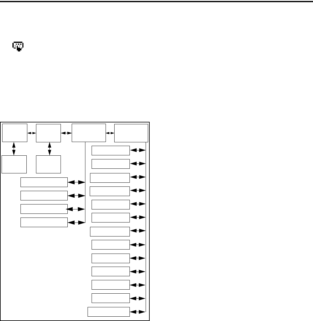
CONVENTIONAL MODE FEATURES
39
for the “Keypad Programming” function. The keypad
programming mode is indicated by “CHNG ZONE”
and in the display.
Keypad programming allows conventional
channel parameters such as the transmit and receive
frequency, Call Guard squelch code, and encryption
key to be changed. In addition, several conventional
mode timers can be changed. It cannot be used to
reprogram disabled channels or any SMARTNET/
SmartZone/P25 Trunked information.
Figure 5-1 Keypad Programming Menu
Flowchart
5.18.2 MENU DESCRIPTION
A menu system is used to select parameters in the
keypad programming mode. A flowchart showing the
keypad programming mode menu structure is located
in Figure 5-1. When the keypad programming mode is
selected by the Keypad Programming option switch or
menu parameter, the first menu parameter “CHNG
ZONE” is displayed as just described. Press the Up/
Down switch to scroll through the available
parameters which are as follows.
•CHNG ZONE
•CHNG CHAN
•SYS PARMS
•CHAN PARMS
Press the F2 (Select) key to select a highlighted
parameter, and press the F1 key from one of the main
menus to exit keypad programming. Pressing it in the
other menus returns to the previous menu. The Up/
Down switch is also used in several menus to scroll
through available selections. Additional information
on this parameters is located in the following sections.
5.18.3 ZONE PASSWORD
NOTE: Make sure that the zone password(s) are not
lost because they cannot be overridden in the field.
The PCConfigure software must be used to display the
lost password or program a new password.
Each zone can be programmed with a password
by the PCConfigure software to prevent unauthorized
reprogramming of zone by keypad programming.
When this password is programmed, it must be entered
before system or channel parameters in that zone can
be changed by keypad programming. The zone pass-
word is programmed in the Zones > Edit Zone screen
of the PCConfigure programmer. This screen is
displayed by clicking the Edit Zone button. A different
password can be programmed for each zone.
When an attempt is made to select a system or
channel parameter in a password protected zone,
“PASSWORD” is flashed. The password is always
eight digits long and is entered using the same proce-
dure as used for the power-up password described in
Section 3.2. After the password is entered, system and
channel parameters for that zone can be reprogrammed
normally.
5.18.4 ZONE CHANGE PARAMETER
The “CHNG ZONE” menu parameter selects the
zone containing the conventional channel to be repro-
grammed. It does not change the zone selected for
normal operation.
Zone Channel
Change
Change
System
Parameters
Channel
Parameters
Select
Zone
Select
Channel
Scan Hold Timer
Tx Timer
Penalty Timer
Conver. Timer
Rx Freq
Tx Freq
Rx Code/NAC
Tx Code/NAC
Tx Power
Tx Tmr On-Off
Squelch Adj*
Chan Spacing*
F1 = Exit/Back
F2 = Select
Up/Down = Scroll
Talk Grp ID**
* Analog Only
** Digital Only
Tx Type Sel***
*** Mixed Mode Ch Only
Key Select
Strapping
Chan Alias

CONVENTIONAL MODE FEATURES
40
Press the F2 switch to select the “ZONE CHG”
parameter and then scroll through the programmed
zones by pressing the Up/Down switch. When the
desired zone is displayed, select it by pressing the F2
switch.
5.18.5 CHANNEL CHANGE PARAMETER
The “CHNG CHAN” menu parameter selects the
conventional channel to be reprogrammed. Disabled or
SMARTNET/SmartZone/P25 Trunked channels
cannot be selected. This does not change the channel
selected for normal operation.
Press the Select switch to select the “CHNG
CHAN” parameter and then scroll through the
programmed channels by pressing the Up/Down
switch. When the desired channel is displayed, select it
by pressing F2 switch.
5.18.6 SYSTEM PARAMETERS
NOTE: If “PASSWORD” is briefly displayed when
attempting to select a parameter, see Section 5.18.3.
The “SYS PARMS” menu parameter selects the
conventional mode timers to be reprogrammed (see
following). Press the F2 switch to select the “SYS
PARMS” parameter and then press the Up/Down
switch to display the desired parameter. Then press the
F2 switch again to select it.
SCAN TIMER - Selects the Scan Hold timer.
Press the Up/Down switch to increment/decrement
the timer in 0.5-second steps from 0-7.5 or set it to
0 seconds to disable it. When the desired value is
displayed, store it by pressing the F2 switch.
TX TIMER - Selects the transmit time-out timer.
Press the Up/Down switch to increment/decrement
the timer in 15-second steps from 0-225 or disable
it by selecting 0 seconds. When the desired value is
displayed, store it by pressing the F2 switch.
PEN TIMER - Selects the penalty timer. Press the
Up/Down switch to increment/decrement the timer
in 15-second steps from 0-225 or disable it by
selecting 0 seconds. When the desired value is
displayed, store it by pressing the F2 switch.
CONV TIMER - Selects the conversation timer.
Press the Up/Down switch to increment/decrement
the timer in 30-second steps from 0-450 or disable
it by selecting 0 seconds. When the desired value is
displayed, store it by pressing the F2 switch.
5.18.7 CHANNEL PARAMETERS
NOTE: If “PASSWORD” is briefly displayed when
attempting to select a parameter, see Section 5.18.3.
The “CHAN PARMS” menu parameter selects
the following conventional channel parameters that
can be reprogrammed. Press F2 switch to select the
“CHAN PARMS” parameter and then press the
Up/Down switch to display the desired parameter.
Then press the F2 switch to select it. The squelch
control parameters are unique to the type of conven-
tional channel selected (analog or Project 25).
NOTE: If a mixed mode channel is selected, both the
Rx Code (analog) and Rx NAC (P25) can be
programmed. In addition, if the Tx Type is Analog, a
Tx Code is programmed, and if it is Digital (P25), a Tx
NAC is programmed.
TX FREQ - Programs the transmit channel frequency.
The digit being changed flashes, and press the Up/
Down switch to select the desired number for that digit
or enter it using the keypad. Then press the F2 switch
to move to the next digit if applicable. If an invalid
frequency is entered, a beep sounds, “INVALID” is
briefly displayed, and the number must be re-entered.
RX FREQ - Programs the receive frequency the same
as the preceding TX FREQ.
SQ ADJ (Analog Only) - Changes the preset squelch
setting on that channel. The default setting is “0” and
values of –7 to +7 can be selected. Increasing this
setting toward +7 causes the squelch to open sooner so
that weaker signals can be received, and decreasing it
toward –7 causes the opposite to occur.
NOTE: The channel spacing is not set with P25 chan-
nels because it is always narrow, and the squelch
cannot be changed because the setting is critical for
proper receiver operation.

CONVENTIONAL MODE FEATURES
41
CHAN SPC (Analog Only) - Selects either wide or
narrow band channel spacing on analog channels only.
Press the Up/Down switch to select “WIDE” or
“NARROW”, and when the desired setting is
displayed, store it by pressing the F2 switch.
NOTE: The next two parameters are programmed only
if the radio is programmed for encryption.
Key Select - Selects the encryption key for the
channel if applicable. The key storage location of 0-15
or 1-16 is displayed. If no keys are programmed, “No
Keys” is displayed. Refer to Section 10.2 for more
information.
Strapping - Selects the encryption strapping mode for
the channel as Clear, Secure, or Switched. Refer to
Section 10.3 for more information.
TG ID (P25 Only) - Selects the talk group for the
selected channel. Press F2 to display the current talk
group ID and then press F2 again to enter a different
ID from 1-65,535. This number must be entered
directly using the DTMF keypad.
Channel Alias - Programs the alias for the channel
(DTMF keypad models only). Up to ten characters can
be entered. Press F2 once to display the current alias
and then press it again to program a new alias. Alpha-
numeric characters are programmed using the 0-9
keys. Pressing a key once enters the first letter on the
key and then pressing it successive times enters the
letters and the number on the key. For example, press
the “2” key twice to enter “B”. Press the F2 key to
move to the next position or press it twice to enter a
space.
TX TIMER - Enables or disables the time-out timer
on the current channel. Press the Up/Down switch to
select the on and off mode, and when the desired
setting is displayed, store it by pressing the F2 switch.
TX POWER - Selects the desired power output level.
Press the Up/Down switch to scroll through the
following choices. When the desired setting is
displayed, store it by pressing the F2 switch.
•Power High - High transmit power
•Power Low - Low transmit power
•Power SW - Switchable power selectable by the
High/Low power switch. This choice is not avail-
able if that switch is not programmed.
CTCSS/DCS Squelch Control (Analog Channel)
TX CODE - Programs the transmit Call Guard
(CTCSS/DCS) code. The currently selected code
and is initially displayed. Press the Up/Down
switch to select the desired code type (CTCSS
analog or DCS digital). Then press F2 to select it
and enter the code number similar to programming
a channel frequency as just described.
RX CODE - Selects the receive codes the same as
TX CODE above.
NAC Squelch Control (Project 25 Channel)
TX NAC - Programs the transmit Network Access
Code (NAC) which can be any number from
0-4095. With later models, this number is displayed
in hexadecimal from 000-FFF. The procedure is
similar to programming a TX FREQ just described.
If an invalid code is entered, a beep sounds,
“INVALID” is briefly displayed, and the code must
be re-entered.
RX NAC - Selects the receive NAC the same as
RX NAC above.
Transmit Type (P25 Mixed Mode Only) - If the
selected channel is a mixed mode, analog and P25
channel, this selects the transmit type. Either Analog
or Digital (P25) can be selected. This then determines
if a Tx Code or Tx NAC is programmed above.

42
SMARTNET/SMARTZONE/P25 TRUNKED FEATURES
SECTION 6 SMARTNET/SMARTZONE/P25 TRUNKED FEATURES
6.1 INTRODUCTION
An overview of the SMARTNET/SmartZone and
P25 Trunked operating modes is located in Section
3.9. The following information describes the features
unique to these modes of operation. Refer to the
“Radio Wide Features” section starting on page 20 for
information on features common to all operating
modes.
6.2 ANALOG AND DIGITAL OPERATION
Either analog or digital operation can be selected
for communication on SMARTNET traffic channels.
Each talk group can be programmed for either type of
operation. Digital operation may be an optional
feature.
6.3 VIEWING UNIT ID
When power is turned on with a SMARTNET/
SmartZone channel selected, the five-digit Unit ID
from 1-65,535 is briefly displayed as IDxxxxx. When
a P25 channel is selected, the eight-digit unit ID from
1-16,777,216 is briefly displayed (see Section 5.17.1).
6.4 STANDARD GROUP CALLS
6.4.1 INTRODUCTION
Standard group calls may be placed to another
radio, group of radios, or a dispatcher, depending on
programming. Most calls are probably this type.
Proceed as follows to place and receive group calls:
6.4.2 PLACING A STANDARD GROUP CALL
1. Turn power on and set the volume as described in
Section 3.1. Select the channel programmed for the
talk group you want to call (see Section 3.3).
2. If the talk group is programmed for encryption and
is not strapped to Clear or Coded, select the desired
mode by pressing the Clear/Secure option switch or
selecting that menu parameter. The status cannot be
changed if the talk group is strapped to Clear or
Coded. Refer to Section 10.3 for more information.
3. Press the PTT switch and begin talking. An optional
talk permit tone may sound to indicate when talking
can begin. Events that may occur are as follows:
•If in the secure mode and your radio is not
programmed with the proper encryption key,
“KEYFAIL” is displayed and the call must be
made in the clear mode or the proper key must be
programmed.
•If the busy tone sounds and “BUSY” is displayed,
the system is busy. Release the PTT switch and
wait for the call back tone to sound. Then press
the PTT switch within 3 seconds.
•If a continuous tone sounds and “NO SYS” is
displayed, you may be out-of-range. Drive closer
or away from shielding objects and try again.
•If your unit ID is invalid, the call is being made to
an invalid group ID, or group calls are not
enabled, “DISABLED ID” is displayed and an
alert tone sounds.
•If an attempt is made to change an analog call
from the clear to secure mode and there is no
available secure channel, “NO SEC” is flashed,
an error tone sounds, and the call is terminated.
•If an attempt is made to change an analog channel
from the secure to clear mode, “SEC ONLY” is
displayed, an error tone sounds, and the call is
terminated. (Calls on digital channels can be
changed if not strapped to clear or secure.)
•If the secure mode is selected by the Secure/Clear
option switch or menu parameter and an attempt
is made to transmit on a channel strapped as clear,
“Clear Only” is displayed and the transmitter is
disabled. Likewise, if the clear mode is selected
and the channel is strapped as secure, “Secure
Only” is displayed and the transmitter is disabled.
6.4.3 RECEIVING A STANDARD GROUP CALL
Calls are received on only the talk group and/or
announcement group programmed for the selected

SMARTNET/SMARTZONE/P25 TRUNKED FEATURES
43
channel (with scanning disabled). When the selected
channel is programmed with both Talk and Announce-
ment groups, only the Talk and Announcement group
IDs are detected. Other IDs in the Announcement
group are detected only if no talk group is
programmed.
When a group call is received, the alias of the
selected channel is displayed. The radio can be
programmed so that the following are also displayed
for 0.5-7.0 seconds or continuously during the call.
PTT ID- The unit ID of the radio placing the call
is displayed.
TG on Rx - The alias of the talk group on which
the call is being received is displayed.
User Group ID - If the group ID of the call being
received is included in a preprogrammed User
Group ID list, the alias programmed in that list for
that group is displayed.
6.5 PRIVATE (UNIT-TO-UNIT) CALLS
NOTE: With P25 Trunked operation, these calls are
called Unit Calls, and they function the same as
Enhanced Private Conversation calls described in the
following information.
6.5.1 GENERAL
Private calls allow calls to be placed to a specific
radio unit. Either the Enhanced Private Conversa-
tion™ or standard Private Conversation modes may be
programmed depending on the capabilities of the radio
system. One difference between these call types is that
the Enhanced type provides an indication that the
called radio is not on the air and the standard version
does not. Operation in each of these modes is
described in the following information.
The Private Call option key is required to place
these calls, and either that key or the Call Response
option key is required to receive them. Private calls are
programmed to operate in one of the following modes:
•Disabled
•Answer-only capability
•List only - Unit IDs can be selected from a prepro-
grammed list only (direct entry using the keypad
is not allowed)
•Unlimited - Unit IDs can be selected from a list
and also dialed directly entered using the keypad.
Both limited and DTMF keypad models can be
programmed to recall the unit IDs from a prepro-
grammed list. However, only DTMF keypad models
can be programmed to directly dial unit IDs.
6.5.2 PLACING AN ENHANCED PRIVATE
CONVERSATION CALL
Recalling From List
1. Momentarily press the Private Call option key or
select that menu parameter and the alias of the last
called radio is displayed. The private call mode is
indicated by in the display.
2. If required, select another radio by pressing the Up/
Down switch until the alias of the desired radio is
displayed.
3. Press the PTT switch of the F2 key to initiate the
call.
(Proceed to the bulleted list which follows Item 3 in
the next section for events that may occur next.)
Direct Entry Using DTMF Keypad
1. Press and hold the Private Call option key until a
tone sounds (approximately 1 second). The last ID
called is displayed, and the private call mode is indi-
cated by in the display.
2. Using the 0-9 keys, dial the ID of the radio you are
calling (five digits must be entered). To erase the last
digit, press the Down key, and to cancel the call,
press the Private Call Option key again.
3. Press the PTT switch to initiate the call. If the
entered number is valid, the display indicates the
alias of the ID if it matches an ID in the call list.
Otherwise, the ID you entered continues to be
displayed.
Events that may then occur are as follows:

SMARTNET/SMARTZONE/P25 TRUNKED FEATURES
44
•If the radio being called is on the air, “WAIT” is
displayed and ringing is heard until the called
party answers or for 20 seconds, whichever
occurs first. Pressing the PTT switch or an option
key stops the ringing but not the call. When the
call is answered, the voice of the called party is
heard.
•If the called radio does not answer within 20
seconds, a continuous tone sounds and “NO
ANS” is displayed.
•If the called radio is not on the air, a continuous
tone sounds instead of the ringing tone and “NO
ACK” is displayed.
•If the busy tone sounds and “BUSY” is displayed,
the called radio has answered the call but the
system is busy. When the system is no longer
busy, the call back tone sounds.
•If your radio or the called radio is inhibited or not
programmed to make this type of call or for the
requested secure mode, “Rspns Only” is
displayed and an alert tone sounds.
•If your radio does not have the proper encryption
key, “KEYFAIL” is displayed and the call must
be made in the clear mode by pressing the Clear/
Secure option key (if strapped to switchable).
Otherwise, load the correct key.
4. When the call is finished or is not answered, end it
by pressing the Private Call option key or the F1
(Exit) key.
6.5.3 PLACING A STANDARD PRIVATE
CONVERSATION CALL
Recalling From List
1. Momentarily press the Private Call option key or
select that menu parameter. The alias of the last
called radio is displayed, and the private call mode
is indicated by in the display.
2. If required, select another radio by pressing the Up/
Down switch until the alias of the desired radio is
displayed.
3. Press the PTT sw or the F2 key to initiate the call.
(Proceed to the bulleted list which follows Item 3 in
the next section for events that may occur next.)
Direct Entry Using DTMF Keypad
1. Press and hold the Private Call option key until a
tone sounds (approximately 1 second). The last ID
called is displayed, and the private call mode is indi-
cated by in the display.
2. Using the 0-9 keys, dial the ID of the radio you are
calling (all six digits). To erase the last digit, press
the Down key, and to cancel the call, press the
Private Call Option key again.
3. Press the PTT switch to initiate the call. If the
entered number is valid, the display indicates the
alias of the ID if it matches an ID in the call list.
Otherwise, the ID you entered continues to be
displayed.
Events that may then occur are as follows:
•The called party answers the call.
•The called party does not answer. Press the
Private Call option key or F1 (Exit) to end the
call.
•If the selected radio ID is not valid, “INVALID
ID” is displayed and an alert tone sounds.
•If the radio system is busy, four low tones sound
and “BUSY” is displayed. When the system is no
longer busy, the call back tone (four beeps) is
heard and the channel is automatically acquired.
Press the PTT switch to continue the call.
•If the call is in the secure mode and the radio does
not have the proper encryption key, “KEYFAIL”
is displayed and the call must be made in the clear
mode by pressing the Clear/Secure option key or
selecting that menu parameter (if strapped to
switchable). Otherwise, load the correct key.
4. When the call is finished or if it is not answered, end
it by pressing the Private Call option key or the F1
(Exit) key.

SMARTNET/SMARTZONE/P25 TRUNKED FEATURES
45
6.5.4 RECEIVING A PRIVATE CALL (ALL
TYPES)
1. When a private call is received, “CALL RCVD” is
displayed and the call tone sounds once.
2. To answer the call, press the Private Call option key
or select that menu parameter and then press the
PTT switch and begin speaking. The unit ID of the
calling radio is displayed. More information
follows:
•If the PTT switch is pressed before the Private
Call option key, the call is transmitted as a group
call.
•If private calls are not permitted (the Private Call
option key/menu parameter is not programmed),
press the Call Response option key or select that
menu parameter to answer the call.
•The call must be answered within 20 seconds or it
is automatically terminated.
•If the system is busy when a response is made,
“BUSY” is displayed and the busy tone sounds.
6.6 TELEPHONE CALLS
NOTE: Telephone calls are available in the P25
trunked mode only.
6.6.1 GENERAL
The telephone call feature allows telephone calls
to be placed and received over the public telephone
system using your radio. Telephone calls are
programmed to operate in one of the following modes:
•Disabled
•Answer-only capability
•List only - Telephone numbers can be selected
from a preprogrammed list only (direct entry
using the keypad is not allowed)
•Unlimited - Telephone numbers can be selected
from a list and also dialed directly entered using
the keypad.
Both limited and DTMF keypad models can place
telephone calls by recalling the telephone number
from a preprogrammed list as just described. However,
only DTMF keypad models can directly dial telephone
numbers using the keypad. The keypad remains active
during a call for overdialing DTMF digits.
6.6.2 PLACING A TELEPHONE CALL
Recalling From List
1. Momentarily press the Phone option key or select
that menu parameter. The alias of the last called tele-
phone number is displayed. The interconnect call
mode is indicated by in the display.
2. If required, press the Up/Down switch to display the
desired number. The alias of each number is
displayed.
3. Press and release the PTT switch and “DIALING” is
displayed. Refer to the bulleted list following step 3
in the next section for events that may then occur.
Direct Entry Using DTMF Keypad
1. Press and hold the Phone option key until a tone
sounds (approximately 1 second). The alias of the
last called telephone number is displayed if it is in
the phone number list. Otherwise, the last eight
digits of the last called telephone number are
displayed. The interconnect call mode is indicated
by in the display.
2. Enter the telephone number using the 0-9, *, and #
keys. To enter a pause (indicated by “P”), press *
and then #. To erase the last digit, press the F1 key.
The number scrolls to the left in the display so that
the eight right-most digits are always displayed.
Numbers up to sixteen digits (including pauses) can
be entered. Press the Phone option key to cancel the
call.
3. Press and release the PTT switch and “DIALING” is
displayed. Events that may occur are as follows:
•If the access is successful, a dial tone sounds and
the dialed number is displayed and sent. Either
ringing or a busy signal is then heard as with a
standard telephone call. When the called party
answers, press the PTT switch to talk and release
it to listen (since the radio is half-duplex, it is not
possible to talk and listen at the same time).

SMARTNET/SMARTZONE/P25 TRUNKED FEATURES
46
Each time the PTT switch is released, a go-ahead
tone is sent to the landside party to indicate when
they can respond. To dial a number after the
connection is made, press the PTT switch and dial
the number using the microphone keypad.
•If the selected telephone number is not valid,
“INVALID” is displayed and an alert tone sounds.
Select a valid number.
•If the system is busy, “BUSY” is displayed and
the busy tone sounds. The call will automatically
proceed when the system becomes available.
•If you are out-of-range or the radio cannot be
accessed for some reason, “NO PHONE” is
displayed and an alert tone sounds.
•If the interconnect call you are making or the
selected secure mode is not authorized,
“REJECT” is displayed and an alert tone sounds.
•If your radio does not have the proper encryption
key, “KEYFAIL” is displayed and the call must
be made in the clear mode using the Clear/Secure
option key or menu parameter (if encryption is
selectable on the channel). Otherwise, load the
proper encryption key.
4. When the telephone call is finished or if it could not
be completed for some reason, end it by pressing the
Phone option key or F1 (Exit) key.
6.6.3 ANSWERING A TELEPHONE CALL
1. When a telephone call is received, “ringing” similar
to a standard telephone is heard and “PHONE” is
displayed.
2. To answer the call, press the Phone option switch or
select that menu parameter and press the PTT switch
to talk and release it to listen. Since the radio oper-
ates half duplex, it is not possible to talk and listen
at the same time.
3. When the call is finished, end it by pressing the
PHONE option switch or F1 (Exit) key.
6.7 CALL ALERT
6.7.1 GENERAL
The Call Alert™ feature allows pages to be sent
and received. With SMARTNET/SmartZone opera-
tion, either the Enhanced Private Conversation™ or
Standard Private Conversation mode may be
programmed depending on the capabilities of the radio
system. With P25 Trunked operation, operation is
similar to the enhanced mode.
6.7.2 ANSWERING A PAGE
1. When a page is received, five beeps sound and
“PAGE” is displayed. The ID of the radio paging
you is stored as the last ID received.
2. To clear or ignore the page, press any option switch.
If the PTT switch is pressed, a group call is placed
on the selected channel.
3. To answer the page as a private call (see Section
6.5), press the Private Call option switch or select
that menu parameter and the alias of the radio
paging you is displayed. Press the PTT switch and
respond. One of the conditions that follow may also
occur:
Enhanced Private Conversation Mode
•If the radio being called is on the air, ringing is
heard until the called party answers or for 20
seconds, whichever occurs first. If no answer
occurs within 20 seconds, a continuous tone
sounds and “NO ANS” is displayed.
•If the radio being called is not on the air, a contin-
uous tone is heard instead of ringing and “NO
ACK” is displayed.
Standard Private Conversation Mode
•If the radio being called is not on the air or does
not answer, you will simply not hear a response.
4. When the call is finished or it could not be
completed for some reason, end it by pressing the
Private Call option switch or the F1 (Exit) key.

SMARTNET/SMARTZONE/P25 TRUNKED FEATURES
47
6.7.3 INITIATING A PAGE
1. With a SMARTNET/SmartZone or P25 Trunked
channel selected, momentarily press the Call Alert
option switch or select that menu parameter. The
alias of the last ID called is displayed.
2. If required, press the Up/Down switch to display the
desired radio. The alias of each number is
displayed.
3. Press the PTT switch or the F2 key and one of the
following occur:
•If five beeps sound, the system received the page
and the paged radio is on the air and received it.
The page mode is automatically exited.
•If the system received the page but the called
radio is not on the air, a single beep sounds and
“NO ACK” is displayed 6 seconds after the PTT
switch is pressed. Auto exit then occurs.
6.8 MESSAGING
NOTE: This feature is not available with P25 trunked
operation.
The messaging feature allows preprogrammed
messages to be sent to a dispatcher. Up to 16 messages
can be preprogrammed, and they are identified by an
alias. If a Message option switch or menu parameter is
programmed, messages are sent as follows:
1. Momentarily press the Message option switch or
select that menu parameter. The alias of the last
message sent is displayed.
2. If required, press the Up/Down switch to display the
desired message. Then send the message by
pressing the F2 key or momentarily pressing the
PTT switch. One of the following events then
occurs:
•If five beeps sound and “ACK RECVD” is
displayed, the message was received and auto-
matically acknowledged by the system.
•If after five tries the message is not acknowl-
edged, a tone sounds and “NO ACK” is
displayed.
6.9 SENDING STATUS CONDITIONS
The status feature allows you to manually or
automatically send your current status to your
dispatcher. Up to eight status conditions can be prepro-
grammed, and they are identified by an alias. If the
Status option switch or menu parameter is
programmed, status conditions are sent as follows:
1. Momentarily press the Status option switch or select
that menu parameter. The alias of the current status
condition is displayed.
2. To change the current status, press the Up/Down
switch until the desired status is displayed. Then to
send the status, press the F2 (Select) switch or
momentarily press the PTT switch. One of the
following events then occurs:
•If five beeps sound and “ACK RCVD” is
displayed, the status was received and acknowl-
edged by the system.
•If after five tries the message is not acknowl-
edged, a tone sounds and “NO ACK” is
displayed.
6.10 EMERGENCY ALARM AND CALL
6.10.1 INTRODUCTION
Emergency Alarms and Calls are separate func-
tions that can be individually enabled or disabled on
each SMARTNET/SmartZone and P25 Trunked
system. The Emergency option switch (or menu
parameter) is required for these functions. Other emer-
gency features are as follows:
•Emergency Alarms are transmitted on the selected
talk group if emergency calls are disabled, and on
the emergency talk group if emergency calls are
enabled.
•Emergency Call talk group selection priority is as
follows. For example, if a global emergency channel
is not programmed, the emergency talk group of the
selected channel is used and so on.
1. Global (radio wide) emergency channel
2. Emergency group of the selected channel

SMARTNET/SMARTZONE/P25 TRUNKED FEATURES
48
3. Talk group of the selected channel
4. Announcement group of the selected channel
•The emergency programming of the system to
which that emergency talk group is linked controls
the emergency operation.
6.10.2 EMERGENCY ALARMS
An emergency alarm is a special transmission that
alerts a dispatcher of an emergency situation. It is sent
automatically by simply pressing Emergency option
switch or selecting the Emergency menu parameter.
The system to which the emergency channel is linked
must have Emergency Alarms enabled. If not, Emer-
gency Alarms are disabled. The alarm is sent on the
control channel using Motorola proprietary signaling.
Proceed as follows to send an emergency alarm:
1. If required, select a channel of a system on which
Emergency Alarms are enabled and then press the
Emergency option switch or select that menu
parameter. The radio then automatically transmits
the emergency alarm.
2. Either Normal or Silent operation can be
programmed. With the Normal mode, the red LED
lights, the emergency tone sounds, and
“EMERGNCY” flashes in the display. This indica-
tion continues to flash until the alarm mode is ended
(see step 4). If silent programmed or the Surveil-
lance mode is selected (see Section 4.7), none of
these indications occur. If “No Receive Activity
During Emergency” is programmed, receive audio,
the front panel LED, and receive icons are disabled
in the receive mode.
3. When the emergency alarm is acknowledged, “ACK
RCVD” is briefly displayed and the emergency
acknowledge tone (two beeps) sounds. Silent opera-
tion may also be programmed in which case no tone
sounds and there is no indication that an acknowl-
edgment occurred.
4. The radio continues to transmit this message until an
acknowledgment is received or the programmed
number of attempts have been made. The emer-
gency alarm mode is exited when radio power is
cycled or by pressing and holding the Emergency
option switch.
6.10.3 EMERGENCY CALLS
General
An emergency call urgently requests access to a
voice channel (an emergency tone usually does not
sound at the console). An emergency call is placed by
pressing the PTT switch after pressing the Emergency
option button or selecting the Emergency menu
parameter. If the Emergency Hot Mic feature is
enabled, the emergency call is automatically trans-
mitted without having to press the PTT switch (see
following description). The system to which the emer-
gency channel is linked must have Emergency Calls
enabled.
Emergency Hot Mic
If Emergency Hot Mic has been enabled for
emergency calls, automatic transmitting occurs with
microphone audio unmuted without having to manu-
ally press the PTT switch. The automatic transmit
period is programmed for 10-120 seconds in 10-
second intervals. If this feature or emergency calls are
not enabled by programming, automatic transmitting
does not occur. This feature is initiated only on the
first press of the Emergency switch. Subsequent
presses do not trigger automatic transmissions. To
reset this function, the channel must be changed or
power cycled.
Placing an Emergency Call
1. If required, select a channel of a system on which
Emergency Calls are enabled and press the Emer-
gency option switch or select that menu parameter.
The Emergency Alarm is then sent as described in
Section 5.10.2 if applicable.
1. The emergency mode is indicated when “ACK
RCVD” is briefly displayed and then
“EMERGNCY” and the emergency talk group are
alternately displayed.
2. If the preceding Emergency Hot Mic feature is
enabled, the call is automatically transmitted
without pressing the PTT switch. If it is disabled,

SMARTNET/SMARTZONE/P25 TRUNKED FEATURES
49
press the PTT switch and begin speaking as with a
standard call.
3. All group calls which follow are then emergency
calls (private, telephone, and call alert calls are not
allowed). If the channel is changed, the call is made
on the emergency talk group programmed for the
new channel. If the Surveillance Mode is enabled
(see Section 4.7), all indicators, lights, and tones are
disabled. If “No Receive Activity During Emer-
gency” is programmed, receive audio, the front
panel LED, and receive icons are disabled in the
receive mode.
4. To exit this mode, cycle radio power or press and
hold the Emergency switch.
6.10.4 EMERGENCY MAN-DOWN FEATURE
This feature requires a special man-down switch
(currently available only from third-party vendors)
that is attached to the accessory connector of the radio.
Then if this feature is enabled by programming and the
radio is in a horizontal position for longer than the
programmed time (0-63 seconds), an emergency
condition is triggered the same as if the Emergency
switch was pressed. The emergency can be canceled
by a press and release of the Emergency switch. Note
that accessories such as speaker-microphones cannot
be used with this feature.
6.11 FAILSOFT OPERATION
If a failure occurs in the SMARTNET/Smart-
Zone or P25 Trunked system so that it cannot be used,
the system directs the radio to automatically enter the
failsoft mode. When in this mode, “FAILSOFT” and
the alias of the selected channel are alternately
displayed. A failsoft tone may also be heard,
depending on how the repeater is programmed.
When in the failsoft mode, operation is in the
conventional mode on the preprogrammed failsoft
channel (a different failsoft channel can be
programmed on each talk group). If a transmission is
attempted before a failsoft channel is located, a contin-
uous tones sounds until the PTT switch is released.
When the radio system returns to normal operation,
this is automatically detected and normal operation
resumes.
6.12 SMARTNET/SMARTZONE/P25 TRUNKED
SCANNING FEATURES
6.12.1 GENERAL
Scanning on a SMARTNET/Smartzone and P25
Trunked systems is called Priority Monitor Scan. The
following are unique features of this type of scanning.
For general scanning information applicable to all
operating modes, refer to Sections 4.8 and 4.9.
•Scanning is turned on and off by the Scan option
switch or menu parameter. Talk groups (channels)
can be programmed so that scanning automatically
starts when the talk group is selected (Autoscan).
•When responding to calls in the scan mode, the
programming of the Talkback Scan parameter deter-
mines if a response always occurs on the talk group
of the call (Active Group) or the Selected Group if
they are different. Transmissions at other times
always occur on the selected talk group.
•Each talk group can be programmed to select one of
the programmed scan lists or “No List” (scanning is
disabled). If scanning is enabled and the selected
channel does not permit scanning, it is automatically
enabled again when a channel is selected that
permits scanning.
•Up to 256 scan lists, each with up to 512 talk groups
from the same system can be programmed. The
selected scan list can be temporarily changed and
edited as described in Section 4.9.1.
•In addition to calls on channels in the scan list,
pages, private/unit calls, and telephone calls are
received while scanning. Private and telephone calls
are not interrupted by priority messages.
6.12.2 PRIORITY TALK GROUP SAMPLING
One talk group in the scan list can be designated a
priority talk group by programming or it can be the
selected talk group. When scanning, messages on a
non-priority talk group are interrupted by messages on
the priority talk group. Priority scanning must also be
supported at the system level for it to occur as
programmed in the radio.

SMARTNET/SMARTZONE/P25 TRUNKED FEATURES
50
6.13 DYNAMIC REGROUPING
The dynamic regrouping feature allows a
dispatcher to change the current talk group or switch
radios to a predefined regrouping channel to receive an
important message. When the console issues a regroup
order, the radio switches to the preprogrammed
regroup talk group.
If the Cancel Dynamic Regrouping option switch
or menu parameter is programmed, it can be used to
exit the dynamic regrouping mode if desired.
Otherwise, if the lock mode was not specified, the
selected talk group can be manually changed and the
previous talk group is reselected if power is cycled. If
a locked regroup command is received, the displayed
talk group cannot be changed manually or by cycling
power. It can be changed only after a clear order is
received from the console.
Dynamic regrouping operates as follows:
1. When this command is received, alternating tones
sound and the radio automatically changes to the
regrouping channel and “DYN REGRP” is
displayed.
2. Manually select the channel corresponding to that
alias. If this is not done, transmission still occurs on
the new channel, but the alternating tones sound
each time the PTT switch is pressed.
3. Talk and listen as usual. When dynamic regrouping
is canceled by the dispatcher, a short tone sounds. If
a standard channel is not selected after this occurs,
transmission is not allowed if the talk group is
assigned as a dynamic regrouping talk group only. If
it is assigned as a normal talk group, normal trans-
missions are allowed.
6.14 SMARTZONE AND P25 TRUNKED
UNIQUE FEATURES
6.14.1 INTRODUCTION
As described in Section 3.9.3, the SmartZone®
mode provides wide area coverage by allowing
roaming between SMARTNET and conventional sites.
The P25 Trunked mode can provide access to a single
trunked site or roaming between several trunked sites.
Operation in these modes is the same as just described
in the preceding sections (6.1-6.13) with the following
additional features:
6.14.2 BUSY OVERRIDE
The busy override feature is enabled at the system
level by the system manager and is not a program-
mable radio feature. It allows a call to be placed even
if not all sites you are calling have a free traffic
channel. The only sites guaranteed to be included are
the Critical Sites and the sites where a Critical User is
located. This feature operates as follows:
1. Assume that you have attempted to place a call and
the system was busy (“BUSY” displayed and busy
tone sounded).
2. Release the PTT switch and then press it for 5
seconds or more. If a chirp tone sounds with the PTT
switch pressed, busy override is occurring.
NOTE: Remember that not all members of the talk
group are receiving your message. Missing
members will start receiving your message as
channels become available.
6.14.3 SITE TRUNKING
Site trunking occurs when a site can no longer
participate in wide area trunking. It is disconnected
from other sides and only supports calls with other
radios on that site and cannot route audio to other
sites. When site trunking is occurring, the radio
searches for other sites that may provide wide area
coverage.
Site trunking ends when a wide area coverage site
is located, the current site is operating again as a wide
area coverage site, an out-of-range condition occurs,
or the failsoft mode is entered. The radio can be
programmed so that “Site Trunking” is displayed and/
or an alert tone sounds when site trunking occurs.
SmartZone and P25 trunked systems can be
programmed for “Disable Site Trunking Operation”.
The radio is then not allowed to start or operate on a
site trunking site. If a site goes into site trunking, the
radio leaves that site’s control channel and attempts to

SMARTNET/SMARTZONE/P25 TRUNKED FEATURES
51
find another valid wide area site. If no wide area site is
available, the radio displays “Out-of-Range”. If a site
adjacent to the current Home Site was in site trunking
but then enters wide area trunking, it is evaluated to
determine if it should move to that site as a better site.
6.14.4 DETERMINING CURRENT SITE AND
SEARCHING FOR NEW SITE
To display the RSSI level of the current site, press
the Site Search option switch or select that menu
parameter. The display then indicates the current site
number as “SITE xx” and the RSSI level as “RSSI
xx”. This mode is then automatically exited.
To scroll through the other programmed sites,
press and hold the Site Search option switch while
“SITE xx” or “RSSI xx” is displayed. If site lock is on
when site search is entered (see following), the radio
will be locked on the new site when this function is
exited.
6.14.5 LOCKING/UNLOCKING A SITE
It is sometimes desirable to stay on a site. To
prevent the radio from searching for a new site, lock it
on the current site by pressing the Site Lock option
switch or selecting that menu parameter. The display
then momentarily indicates the site alias to indicate
that the current site is locked (“x” is the current site
number). To unlock the site, press the Site Lock switch
again or the F2 (Select) key and “UNLOCK” is
momentarily displayed.
6.14.6 ZONEFAIL SITE LOCK
This is an optional feature that can be enabled
only by factory programmed. It is not programmed by
the PCConfigure software, and does not require any
special inputs from the infrastructure to operate. This
feature is intended to prevent some of the confusion
resulting from a site controller failure. When this
occurs, all sites go into the Site Trunking mode and
radios continue to roam normally according to RSSI
level. The result is that the various radios selected by a
particular talk group may be operating on different
sites and are unable to talk to each other (see Section
6.14.3 for more Site Trunking information).
With the Zone Fail Site Lock feature enabled, the
radio continues to roam normally when the system
zone controller is active. However, if the zone
controller fails, this is detected and the Zone Fail Site
Lock mode is entered. The only site the radio is then
allowed to operate on is its home site. If its home site
is not available, “Out-of-Range” is displayed. A zone
controller failure is detected by determining that every
site in the dynamic site list is in Site Trunking.
Currently, this condition must be detected for at least 1
minute for the Zone Fail Site Lock mode to be
selected.
The result of this operation is that all radios with
the same programmed home site are forced to the
home site to communicate which ensures that they can
continue to communicate. If the home site is not avail-
able, the Out-of-Range condition tells the user to
attempt communication on another system or by some
other means.
6.14.7 P25 WIDE AREA SCAN
Introduction
This feature is intended to enhance roaming
performance, especially when system level steering
via radio or talk group permissions is used.
Normal P25 and SmartZone Control Channel Hunt
The following control channel search methods are
normally used to find a control channel:
Short Hunt - The dynamic array of 7 (or 15) adja-
cent sites is searched. This list is saved on power
down and loaded again at power up. It is erased
whenever parameters are downloaded to the radio
by the PCConfigure programmer.
Long Hunt - If no valid control channel is located
by the preceding short hunt method, the radio
searches the list of control channels programmed
into the radio by the PCConfigure programmer.
Full Spectrum CC Scan - If the two preceding
methods do not locate a control channel, every
channel available to the radio is searched.
Talkgroup Steering Via System Access Permissions
In order to use system channel resources more
efficiently, some system operators are using system

SMARTNET/SMARTZONE/P25 TRUNKED FEATURES
52
access permissions to steer certain talkgroups to
particular sites. For example, a police department may
be allowed to use only Site 1, and a public works
department may be allowed to use only Site 2.
The problem with this operation is that every time
a different talk group is selected, the access permission
may be different and a different site may need to be
accessed. This could result, in a worst case, in a delay
of up to 30 seconds in finding a new site. This could
occur if there are no valid sites for the new talk group
in the dynamic site list.
P25 Wide Area Scan
A feature called Wide Area Scan can be
programmed to minimize the problem just outlined.
This feature is programmed on the Talk Group list
screen selected on the P25 System screen. When Wide
Area Scan is selected, talk group site preferences are
no longer available. However, System Site Preference
lists can still be used. The Wide Area Scan feature
functions as follows:
1. Assume TG1 is selected. If it is the first time this
talk group is selected, normal searching for a control
channel occurs according to the hunt methods
previously described.
2. When another talk group is selected, the active valid
site for TG1 is stored in EEPROM memory.
3. The next time TG1 is selected, the following proce-
dure is performed before performing the normal
hunt methods previously described.
a. The last valid site ID and its receive and transmit
channel numbers are loaded from EEPROM
memory.
b. The dynamic site list is checked to see if any
newer receive/transmit channel information is
available for the last site ID.
c. The best receive/transmit information is used and
the radio checks to see if this control channel is
available.
The result of the preceding operation is that the
radio has a reasonable chance of finding a valid site,
usually on the first try. This greatly reduces access
time, even on systems which have highly restricted
talk group based access.

53
MISCELLANEOUS
SECTION 7 MISCELLANEOUS
7.1 SUPERVISORY TONES
Single Beep (Alert Tone)
•Power was turned on and a successful power-up
sequence occurred (Section 3.1).
•The time-out timer is about to expire or the penalty
timer has expired (Section 4.3).
•The conversation timer is about to expire (Section
5.7).
•The system received your page but the paged radio
is not on the air (Section 6.7).
•Telephone interconnect is not operational (Section
6.6).
Continuous Tone (Invalid Condition)
•A transmission is being attempted on a conventional
channel programmed as receive-only.
•The transmitter is disabled by the busy channel
lockout feature (Section 5.4).
•The transmitter has been disabled by the time-out
timer feature (Section 4.3).
•The transmitter has been disabled by the conversa-
tion timer (Section 5.7).
•An out-of-range condition exists (SMARTNET/
SmartZone and P25 trunking only).
•A transmission is being attempted before the penalty
timer has expired (Section 5.6).
•Dynamic regrouping has been exited but the
dynamic regrouping channel is still selected
(Section 6.13).
Single Short Medium-Pitch Tone
•A valid key has been pressed.
Single Short Low-Pitch Tone
•An invalid key has been pressed.
Medium Tone (No Acknowledge)
•The paged radio did not acknowledge the page
(Section 6.7).
•The message that was sent has not been acknowl-
edged (Section 6.8).
•The status condition that was sent has not been
acknowledged (Section 6.9).
Five Beeps (Recurring)
•The page was received (Section 6.7).
Two Short Tones
•A private call was received (Section 6.5).
Five Beeps
•The paged radio received the page and acknowl-
edged it (Section 6.7).
•The message that was sent has been received and
acknowledged (Section 6.8).
•The status condition that was sent has been received
and acknowledged (Section 6.9).
Four Beeps
•The emergency alarm condition was acknowledged
(Section 6.10).
•Four low tone beeps indicate call back mode (the
system is no longer busy)
Alternating Tone
•Dynamic regrouping has occurred (Section 6.13).
•Dynamic regrouping has occurred but the
regrouping channel is not selected (Section 6.13).
Busy Signal
•The radio system is busy or a busy condition exists
when making a telephone call.
Three Medium Pitch Tones
•A channel is available after a busy condition
occurred (SMARTNET/SmartZone only).

MISCELLANEOUS
54
7.2 ERROR MESSAGES
The following are definitions of the various error
messages that may be displayed.
Aff Failed - A group affiliation attempt has received a
FAILED response from the system. The precise reason
for a FAILED response is manufacturer dependent.
Aff Deny - A group affiliation attempt has received a
DENIED response from the system. The precise
reason for a DENIED response is manufacturer depen-
dent. One common cause is that the group is
disallowed on the site/RFSS that the radio is
attempting to affiliate on.
Aff Refusd - A group affiliation attempt has received
a REFUSED response from the system. The precise
reason for a REFUSED response is manufacturer
dependent.
Answr Only - The user has attempted to initiate a
private call or interconnect call and the feature is
programmed for answer only.
Bad Band - A profile/or user parameters have been
downloaded with PCConfigure that are for a band
different from the hardware of the radio.
Bad ESN -The ESN of the radio is not valid. This
error is usually only seen in the factory when first
programming brand new logic boards.
Bad Fl Fmt - A profile/or user parameters have been
downloaded to the radio that do not match the file
format supported by the firmware/software in the
radio.
Bad Hrdwar - The ESN of the radio is not valid. This
error is usually only seen in the factory when first
programming brand new logic boards.
Batt Low - The battery voltage has been detected as
being low.
Busy - A call has been attempted and the system has
responded that no channels are available for assign-
ment.
Busy Tmout - The radio previously received a busy
response from the system and it has not received a
channel grant before the busy time-out timer has
expired
Disabled - The selected channel is disabled.
Clear Only - The selected channel or group is
strapped clear only and that a secure call can not be
made.
Corupt Prm - The radio has detected that its profile/
user parameters are not valid because the functional
blocks can not be identified.
Denied - A group call attempt has received a DENIED
response from the system.
Deny - A unit or interconnect call attempt has received
a DENIED response from the system.
Disabled - The feature that the user is attempting to
use has been disabled on the radio either by program-
ming or by factory options.
DSP Failed - The main processor and the DSP have
failed to complete their startup procedure at powerup.
EEPRM Fail - The main processor has timed out
while trying to validate or invalidate the profile/user
parameters in the EEPROM.
Encryp Bad - The main processor and the Encryption
Module have failed to complete their startup procedure
at power up.
Fixed High - The selected channel or group is
strapped to high power and thus low power can not be
selected.
Fixed Low - The selected channel or group is strapped
to low power and thus high power can not be selected.
Too Hot - The mobile has passed the hot temperature
threshold. Under these conditions the radio will only
transmit in low power.
Invalid - The received input from the user does not fit
the criteria necessary for the feature.
Invalid ID - The received ID from the user was not a
valid ID.

MISCELLANEOUS
55
Invald Key - The key pressed by the user was not
valid for the current situation.
Invld Ch - The channel entered by the user in keypad
programming is not valid.
Key Fail - The encryption key required by the current
selected group/channel is not valid.
Kypd Lockd - The keypad lock function is active and
key presses are not accepted in this mode.
Kset Fail - The encryption key set chosen by the user
is not valid.
List Only - Direct entry of a unit ID or phone number
is disabled.
Locked - A selector lock command has been received
and zone and channel changes are not accepted.
Lost Signl - Signal from the infrastructure has been
lost during an interconnect call.
Low Power - The current channel is strapped to low
power and that the user can not select high power at
this time.
Msg Failed - The current channel is strapped to low
power and that the user can not select high power at
this time.
Narrow - The current conventional channel is
programmed as a narrow channel.
No Ack - The radio did not receive an ACK for the
current signaling attempt.
No Edit - The current list is not able to be edited.
No Encrypt - Encryption is not available for the
selected channel.
No List - No list is available for the selected channel.
No Message - No message is programmed for trans-
mission.
No Reply - Radio cloning failed due to no response.
No Service - OTAR service is not available.
No Site - No site with a verified ID is yet on the
dynamic site list.
No Keys - No keys are available for the key select
function.
Out Of Rng - This error indicates no control channel
has been found for trunking operation.
Parms Fail - The checksum of the profile / user
parameters does not match the calculated checksum.
This indicates that there is an error in the parameters
file. This message only occurs if the redundant copy of
the parameters is also corrupt or is unable to be used.
Rekey Fail - This error indicates a failure in a
rekeying process.
Rx Only - The selected channel is Rx only.
Sts Failed - No acknowledgement was received while
sending a status report.
Timeout - A time out has occurred in attempting the
current function.
Too Hot - The mobile has passed the TOO HOT
temperature threshold. Under these conditions the
radio will not allow Tx.
Tx Timeout - The Tx time-out timer has expired and
Tx has been terminated.
VOLTAGE HI - The input voltage to the mobile is
too high.
VOLTAGE LO - The input voltage to the mobile is
too low.
Write Fail - The radio is unable to write to the
EEPROM.
7.3 SYSTEM OPERATOR PROGRAMMING
As noted several times in this manual, program-
ming determines the availability and specific operation
of many features. This usually refers to the program-
ming performed by the PCConfigure programmer

MISCELLANEOUS
56
when the radio was set up, not to any programming a
user can perform. If a feature is controlled by a front
panel option switch and that switch is not available, it
is probably not available.
If the Keypad Programming option switch is
available, you can reprogram some conventional
channel parameters. Refer to Section 5.18 for more
information.
7.4 SPEAKING INTO MICROPHONE
For best results, hold the radio about 1-2 inches
from your mouth and speak at a normal conversational
level. Do not shout since it distorts your voice and
does not increase range. Make sure that the PTT (push-
to-talk) switch is pressed before you begin to speak
and released as soon as the message is complete.
7.5 OPERATION AT EXTENDED RANGE
When approaching the limits of radio range, the
other party may not be able to hear your transmissions
and there may be an increase in background noise
when messages are received. You may still be out of
range even though you can hear a message. The reason
for this is that the signal you are receiving is usually
transmitted at a higher power level than the one trans-
mitted by your radio. Communication may be
improved by moving to higher ground or away from
shielding objects such as tall buildings or hills.
7.6 LICENSING
A government license is usually required to
operate this radio on the air.
7.7 RADIO SERVICE
If the radio is not responding to any key presses,
the keypad may be locked. Refer to Section 3.6 for
more information.
If “PASSWORD” is briefly displayed when
power is turned on and you are prompted to enter a
password, the Power-Up Password feature is enabled.
Refer to Section 3.2 for more information.
If “UNPROGRAMD” is displayed, the cause
could be any of the following:
•An unprogrammed channel is selected. Select a
programmed channel.
•The selected channel is programmed for an option
that is not installed or an error in programming was
detected. Reprogram the radio.
If no characters appear in the display, the battery
may be discharged or defective. Try another battery. If
some other problem is occurring, turn power off and
then on again to reset the control logic. Also make
sure that the controls are properly set. If it still does
not operate correctly, return it for service.
NOTE: There are no user-serviceable components in
the radio. Altering internal adjustments can cause
illegal emissions, void the warranty, and result in
improper operation that can seriously damage the
radio.

57
DETERMINING AVAILABLE OPTIONS
SECTION 8 DETERMINING AVAILABLE OPTIONS
8.1 GENERAL
This manual describes the operation of all
features that are currently available for the 41xx radio.
However, many of these features are optional and
therefore may not be available in your radio. For
example, Project 25 trunked operation is optional and
may not be available.
Availability of optional features is controlled by
factory programming of the control logic. Only those
features that are specifically ordered and enabled in a
particular radio are available for use and can be
programmed. The features controlled by factory
programming are as follows:
P25 Options
•P25 conventional data
•P25 trunked data
•P25 conventional operation
•P25 trunked operation
Encryption Options
•DES
•DES-XL
•DES-OFB
•AES
OTAR Options
•OTAR P25 conventional
•OTAR P25 trunked
Trunking Options
•STAR roaming with P25 trunked operation [1]
•SMARTNET analog operation
•SmartZone analog operation
•Digital SMARTNET/SmartZone
Feature Options
•Keypad programming (Federal Gov’t users only)
•512 channels/talk groups (41xx only, currently
standard)
•DTMF Keypad support (4100 only)
•Zonefail site lock
[1] 4100 radios require that this option be enabled to roam
across zone controller boundaries.
Currently, the only operating mode that is stan-
dard with all models is the conventional analog mode.
Other variables such as frequency range are hardware
dependent instead of software dependent.
8.2 UPGRADING A RADIO WITH NEW
OPTIONS
The capability exists to upgrade radios in the field
with new features. A new feature can be purchased
and a special encrypted code string keyed to the ESN
(Electronic Serial Number) of the radio is then
provided by the E.F. Johnson Company. This string is
in the form of a computer file, and is downloaded to
the radio using the PCConfigure programming soft-
ware. This is initiated by clicking the “Update
Options” button on the Radio Options screen shown in
Figure 8-1.
8.3 USING PCCONFIGURE TO DETERMINE
OPTIONS
To determine what software options have been
enabled in a particular radio, it is recommended that
you use the PCConfigure™ programming software to
read and display what options are installed. Proceed as
follows:
1. Connect the computer to the radio and start the
program as described in the documentation included
with the PCConfigure software.
2. Select the 41xx radio type by selecting menu
parameter Radio > Series > 4100 Portable.
3. To display the Radio Options screen shown in
Figure 8-1, select Transfer > Read Options From
Radio.
4. The check boxes indicate which options are enabled
in the radio. They are for informational purposes
only and cannot be edited.
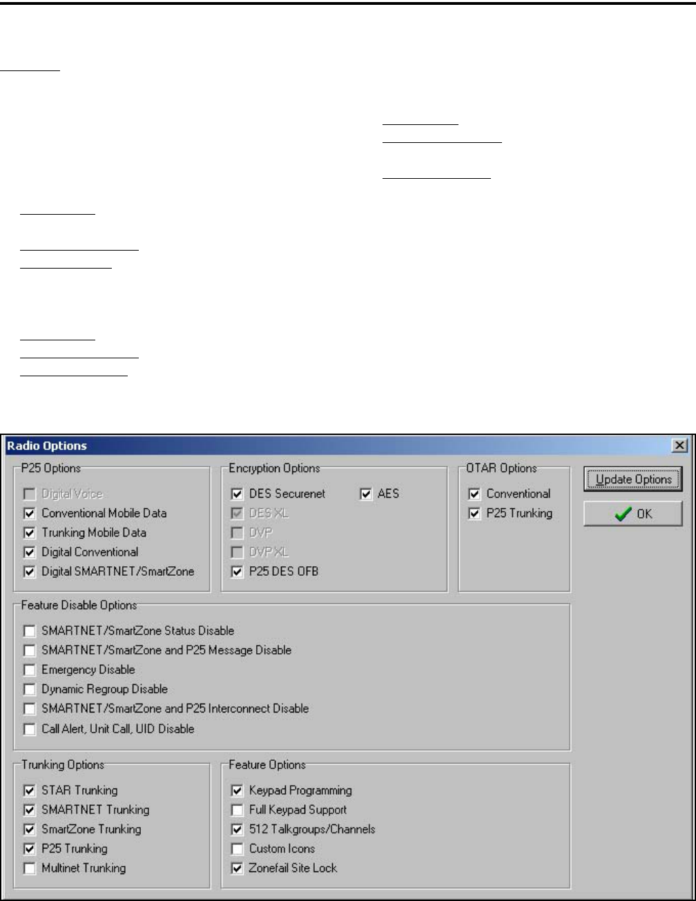
DETERMINING AVAILABLE OPTIONS
58
Examples
The following are examples of items that need to
be checked to program various optional features:
P25 Conventional Operation with DES Encryption
and OTAR
P25 Options - Digital Conventional, Conventional
Radio Data
Encryption Options - P25 DES OFB
OTAR Options - Conventional
P25 Trunked Operation with DES Encryption
P25 Options - Digital Conventional
Encryption Options - P25 DES OFB
Trunking Options - P25 Trunking
SMARTNET Analog and Digital Operation with
Encryption
P25 Options - Digital SMARTNET/SmartZone
Encryption Options - DES Securenet and DES-
OFB
Trunking Options - SMARTNET Trunking
NOTE: The “Feature Disable Options” are currently
not used, so those features are always available.
Figure 8-1 PCConfigure Radio Options Screen

59
PASSWORD DESCRIPTION
SECTION 9 PASSWORD DESCRIPTION
9.1 NEW PASSWORD ENHANCEMENTS
9.1.1 INTRODUCTION
A new enhanced password feature is now avail-
able for 4100 portables and 4300 mobiles. The number
of passwords have been increased along with the
number of functions that can be under password
control. The single Power-On password has been
replaced by the following passwords:
•Four Power-On (User x) Passwords
•Download and Upload Passwords
•Master Password
9.2 PROGRAMMING PASSWORDS
9.2.1 GENERAL
With new versions of PCConfigure, the “Pass-
word at Power Up” parameter has been removed from
the Global screen as just described. Passwords are now
programmed using a password management screen
displayed by the Tools > Password Management
menu. The applicable radio must be connected to the
computer and powered up to display this screen.
Password data is transferred and stored in an
encrypted format for security purposes. In addition,
actual passwords are never displayed. They are always
indicated by eight asterisks (********). Therefore, it
is not possible to determine what passwords are in a
radio using the PCConfigure software.
Passwords must be 1-8 characters in length and
consist of the numbers 0-9. Zeros are valid characters
in any location, even as leading characters. Initially, all
passwords are null (deleted) characters. Therefore,
when initially programming a password, no entry is
required in the “Original/Master Password” box.
9.2.2 LOST PASSWORDS
If a password is lost, it can be changed using
PCConfigure by entering the Master password (see
following). If even the Master password is lost or was
not used, all passwords can be erased using the
PCTune software as follows:
1. With PCTune 1.1.1.0 or later, simply select Radio >
Reset Passwords. Only password information is
erased.
2. With earlier versions of PCTune, after starting the
PCTune program, press SHIFT CTRL E to toggle
the following Erase EEPROM function (otherwise it
is grayed and not selectable). Then Select Radio >
Erase EEPROM > Params Only. All password and
personality information is erased, so the radio must
be reprogrammed. NOTE: DO NOT SELECT
“COMPLETE” because that erases all information
and the radio must then be sent back to the factory
to make it usable again.
9.2.3 CHANGING PASSWORD
An assigned password can be changed by the user
if the “Set User Password” option switch or menu
parameter (4100 only) is programmed. Selecting this
function displays prompts for entering and confirming
a new password.
NOTE: With the 4100 portable and 4300 Handheld
Control Unit, it is recommended that a number key not
be used for this function because the password mode is
exited if that key is pressed to enter a number.
9.2.4 PASSWORD ENTRY PROCEDURE
Whenever a password is requested, it is entered as
follows:
43xx Mobile - Rotate and press the Select switch.
41xx Portable - With DTMF keypad models, enter
each number using the keypad and press the F2 (Enter)
key after the last digit is entered. With limited keypad
models, enter each number by pressing the Up/Down
switch and press the F2 key after each digit.

PASSWORD DESCRIPTION
60
9.3 PASSWORD DESCRIPTION
9.3.1 USER (POWER-ON) PASSWORDS
When a User Password is enabled, it must be
entered each time radio power is turned on. Up to four
different User Passwords (User 1/User 2/User 3/
User 4) can be programmed. Currently, the same radio
features are enabled for each. Entering any User Pass-
word at power up enables normal radio operation.
9.3.2 DOWNLOAD/UPLOAD PASSWORDS
Separate Download (write) and Upload (read)
passwords can be programmed to prevent unautho-
rized downloading or uploading of radio programming
parameters. When one or both of these passwords are
used, the proper password must be entered to perform
the operation. A “User” password is not required to
upload or download parameters.
9.3.3 MASTER PASSWORD
The Master Password overrides all the preceding
passwords. It can be used by a system administrator as
a “pass key” to a password controlled function or to
change a lost or inadvertently changed password.
Master passwords are set up and changed the same as
the other passwords. It does not override the following
Zone Password.
9.4 ZONE PASSWORD
NOTE: The programming and usage of this password
has not changed. It is independent from the preceding
passwords, and programmed in the Zone > Edit Zones
and Channels screen.
A zone password can also be programmed with
the 43xx mobile and 41xx portable. It prevents unau-
thorized reprogramming of zones by keypad program-
ming. When this password is used, it must be entered
before system or channel parameters in that zone can
be changed. The zone password is programmed in the
Edit Zones and Channels screen. This screen is
displayed by clicking the Edit Zone button on the
Zone screen.
A different password can be programmed for
each zone. When a password protected zone is
selected, “PASSWORD” is flashed the first time an
attempt is made to select a system or channel
parameter in that zone. Each digit of the password is
then entered as previously described. The password is
always eight digits long, and after the eighth digit is
entered, system and channel parameters for that zone
can be reprogrammed normally.

61
SECURE COMMUNICATION (ENCRYPTION)
SECTION 10 SECURE COMMUNICATION (ENCRYPTION)
10.1 GENERAL
10.1.1 INTRODUCTION
This radio may be equipped to provide secure
communication on some or all channels. This feature
encrypts the voice so that it can be understood only by
someone using a radio equipped with a similar encryp-
tion device and encryption codes.
When a secure call is received or transmitted,
is indicated in the display (see Section 10.2.7). If
equipped with the Clear/Secure option switch and the
current channel is programmed to allow switch selec-
tion, secure communication can be manually enabled
and disabled by that switch. Otherwise, channels are
strapped to Clear or Coded operation (see Section
10.3). Secure communication can be programmed on a
per channel or per talk group basis to operate in
various ways. More information follows.
10.1.2 ENCRYPTION ALGORITHMS
SecureNet™
SecureNet encryption digitizes the voice and then
encrypts it using the DES or DVP algorithm. It uses a
64-bit encryption key. The SecureNet protocols
include the following algorithms:
•DVP (Digital Voice Privacy) is an earlier encryption
method that is self synchronizing using cipher feed-
back. It was originally designed to be used by
anyone needing protection from unauthorized
eavesdropping.
•DES (Data Encryption Standard) provides a higher
level of security, and also uses cipher feedback. It
was originally designed to be used only by the
Federal government.
•DVP-XL/DES-XL - A disadvantage of the DVP and
DES encryption types is reduced communication
range when compared to clear voice. The DES-XL
and DVP-XL methods were designed to provide
better range but at the cost of lower voice quality.
They use a different type of feedback called counter
addressing.
•DES-OFB - A form of DES encryption for digital
channels that uses output feedback. This protocol
does not result in the degraded range that occurs
with analog channels.
AES (Advanced Encryption Standard)
A new encryption standard called AES is
replacing DES-OFB encryption on digital (P25) chan-
nels. It uses a 128-, 192-, or 256-bit encryption key
instead of the 64-bit key used with DES. EFJohnson
radios currently support only 256-bit AES keys. The
type of encryption (DES or AES) is determined by the
type of encryption key that is loaded (see Section
10.2), and not by the PCConfigure programming soft-
ware. AES encryption, like DES encryption, is an
optional radio feature that must be purchased and then
enabled at the factory.
10.1.3 ENCRYPTION AVAILABLE WITH
VARIOUS CHANNEL TYPES
Analog Channels
On analog conventional and SMARTNET/Smart-
Zone channels, DES and DES-XL encryption is used
to provide secure communication. The DES-XL type
is available only with later 41xx portables equipped
with the Motorola UCM (Universal Crypto Module).
Digital Channels
On digital Project 25 and SMARTNET/Smart
Zone channels, the DES-OFB or AES protocol is used.
10.1.4 FIPS AND NON-FIPS MODES
FIPS 140-2 is a Federal Information Processing
Standard for encrypted radios used by the Federal
Government. This standard specifies Federal security
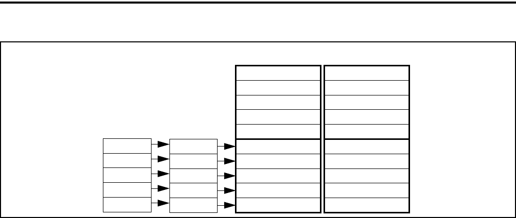
SECURE COMMUNICATION (ENCRYPTION)
62
Figure 10-1 Key Selection Example
Keyset ID 2
Algorithm ID
Update Item (Opt)
Time/Date (Opt)
Keyset Name (Opt)
SLN 23
SLN 25
Keyset ID 1
Algorithm ID
Update Item (Opt)
Time/Date (Opt)
Keyset Name (Opt)
Key #21: Key ID 54
Storage Loc.
SLN 24
SLN 22
SLN 21
Number (CKR)
3
5
4
2
1
PID
Key #22: Key ID 65
Key #23: Key ID 67
Key #24: Key ID 69
Key #25: Key ID 73 Key #25: Key ID 90
Key #24: Key ID 91
Key #23: Key ID 99
Key #22: Key ID 98
Key #21: Key ID 94
Crypto Group A
Keyset A1 Keyset A2
Zone 1, Chan 2
Zone 2, Chan 4
Zone 2, Chan 5
Zone 3, Chan 1
Zone 3, Chan 2
requirements for cryptographic modules for a wide
range of applications and environments.
10.2 ENCRYPTION KEYS
10.2.1 INTRODUCTION
An encryption key is a cryptographic variable
that is required by the encryption algorithm to encrypt
and decrypt voice or data. To maintain system security,
these keys must be protected from disclosure and also
periodically replaced or updated.
With the AES and DES encryption used by
EFJohnson radios (see Section 10.1.2), the same
encryption key is used by both the encrypting
(sending) and decrypting (receiving) radio. AES
encryption keys are generated from a string of 64
hexadecimal characters, and DES keys are generated
from a string of 16 hexadecimal characters. Another
four hexadecimal characters are used to specify the
key ID. Multiple keys can be loaded into a radio using
OTAR or manual loading.
When an encrypted message is transmitted, the
encryption Algorithm ID (ALID) and key ID (KID)
are usually included in the message. This tells the
receiving radio which key and algorithm must be used
to decrypt the message.
If an attempt is made to transmit a secure
message without loading the corresponding key,
“KEYFAIL” is displayed. The message must then be
transmitted in the clear mode (this is possible only if
the channel is strapped to “switchable”) or the key
must be loaded.
10.2.2 KEY AND ALGORITHM IDS
Each encryption key is programmed with a Key
ID (also called Logical ID). This ID plus the algorithm
ID (ALGID) is transmitted in the message. The radio
receiving the message must have a key programmed
with the same IDs in order to decrypt it.
10.2.3 PID/SLN KEY MANAGEMENT MODES
NOTE: The term “SLN” from the Project 25 specifica-
tion is equivalent to “CKR” (Common Key Reference)
also used to define this parameter.
The channels, talk groups, and other calls that use
encryption are linked to a specific Physical ID (PID)
when the radio is programmed using the PCConfigure
programming software. For example, Zone 1, channel
1 could be programmed to select the key in PID 1 and
Zone 1, channel 2 could select the key in PID 3. The
PID ranges are 0-15 when the PID mode is selected,
and 1-16 when the SLN mode is selected (see
Figure 10-1).
PID or SLN key management modes can be
programmed on the Global programming screen. More
information on these modes follows.
PID Mode - The PID mode can be used only when
keys are loaded using the Motorola KVL 3000

SECURE COMMUNICATION (ENCRYPTION)
63
keyloader. When this mode is selected, keys are loaded
directly into a PID of 0-15 that corresponds to the PID
programmed for each channel (if applicable). A Keys
Table is not programmed with this mode.
SLN Mode - The SLN mode must be selected is either
OTAR (Over-The-Air-Rekeying) or the EFJohnson
System Management Assistant (PDA keyloader) is
used. It can also be used if OTAR is not used. With
this mode, keys are loaded into a SLN (Storage Loca-
tion Number), typically from 0-4095. A Keys Table
must then be programmed to link channel PIDs to a
specific SLN.
The use of this type of indirect linking allows keysets
and key IDs to be changed via OTAR while keeping
the mapping from the channel or talk group the same.
For example, as shown in Figure 10-1, PID 4 selects
SLN 24 which selects key slot 24 in both keysets. This
slot contains Key ID 69 in Keyset 1 and Key ID 91 in
Keyset 2. Only one keyset is active at a time.
10.2.4 MAINTAINING KEYS IN MEMORY
The radio may need to be connected to a constant
power source to preserve the encryption keys in
memory. The programming of the Infinite Key Reten-
tion parameter determines if keys are permanently
stored in memory or erased soon after power is
removed.
When Infinite Key Retention is enabled, keys are
stored in memory and are not lost when power is
removed. If it is disabled, they are maintained only
until the storage capacitance discharges. With 4100
models, storage capacitors maintain the supply voltage
(and encryption keys) for approximately 30 seconds
without power applied. Therefore, when changing the
battery, make sure to reattach another within 30
seconds.
With 5300 models, the keys are maintained for
approximately 8 hours with this feature disabled.
However, a tamper switch causes immediate key
erasure when the radio cover over the logic board is
removed.
10.2.5 ENCRYPTION KEY SELECT
NOTE: This feature is available on conventional
channels only.
When multiple encryption keys are programmed
(see preceding information), the Key Select option
switch can be programmed to allow selection of
another key for the current channel. This feature
changes the PID (hardware location) of the key, and
the change is permanent (cycling power or selecting a
different channel does not reselect the original key).
Therefore, to switch back to the original key, it must
be manually reselected. Proceed as follows to select a
key:
1. Press the Key Select switch or select that menu
parameter and HWKEY x is displayed. The “x”
indicates the current key PID selection.
2. Press the Up/Down switch to display the desired key
and then press the F2 (Select) key to select it. Press
the F1 (Exit) or Key Select switch again to return the
display to normal operation.
10.2.6 ENCRYPTION KEY ERASE
A Key Erase menu item can be programmed that
allows the user to permanently erase all stored keys. If
OTAR TEK and KEK keys are stored, all keys of both
types are erased. This function can be used to ensure
that unauthorized encrypted calls can no longer be
placed or received by a radio.
10.2.7 ENCRYPTION ICON OPERATION
Basically, the encryption icon is on continu-
ously whenever a secure call is received or trans-
mitted. Other operation is as follows:
•When a secure call is received on a digital channel
in either the secure or clear mode, this icon flashes.
•When a clear call is received on a digital channel in
the secure mode, this icon is on continuously.
•There is a programmable option on the Radio Wide
screen to sound a beep whenever a secure call is
received on a clear channel.
10.3 CLEAR/SECURE STRAPPING
10.3.1 TRANSMIT MODE OPTIONS
The following transmit options are available
when encryption is selected:

SECURE COMMUNICATION (ENCRYPTION)
64
Clear - All calls are in the clear mode unless
responding to a secure call. If the response is then
made within the delay time (see Section 4.8.4), it
occurs in the secure mode.
Secure - All calls are made in the selected secure
mode.
Switched - The mode is selected by the Clear/Secure
switch. When the clear mode is selected by this
switch, “CLEAR” is flashed, and when the secure
mode is selected, “SECURE” is flashed.
If the channel has been strapped “Clear” and the
option switch selects the “Secure” mode on power up
and a transmission is attempted, “Clear Only” is
displayed and transmitting is disabled. Likewise, if the
channel is strapped “Secure” and the option switch
selects the “Clear” mode on power up and a transmis-
sion is attempted, “Secure Only” is displayed and the
transmitter is disabled.
The radio can be programmed to ignore the
“Clear” or “Secure” switch setting (“Ignore Clear/
Secure Switch When Strapped” selected on Global
screen). These preceding indications then do not occur
and transmissions always occur in the strapped mode.
NOTE: If all channels/talk groups are strapped clear
or secure and no Clear/Secure option switch or menu
parameter is programmed, this parameter must always
be selected (see following).
If the Clear/Secure switch or menu parameter are
not programmed, the radio is always in the last known
state (usually Clear) and there is no way to change it.
For example, if the last known state is Clear and this
parameter is not selected, it is never possible to
transmit a Secure message on a channel strapped
Secure because all that happens is transmitting is
disabled, an error tone sounds, and “Sec Only” is
displayed.
10.3.2 RECEIVE MODE OPTIONS
The following receive options can be
programmed with conventional operation. With
SMARTNET/SmartZone and P25 Trunked operation,
encrypted calls are received if the proper key is
programmed.
No Autodetect - Only signals coded like the transmit
signals are received.
Secure Autodetect - Both clear and secure signals are
automatically detected. This mode is automatically
selected if the transmit mode is switch selectable.
Proper Key Autodetect
Analog Channels
When this feature is disabled and a message is
received with the wrong key, the audio unmutes
and garbled (encrypted) audio is heard. However, if
this occurs with this feature enabled, the audio
remains muted.
Digital Channels
When this feature is enabled and a message is
received with a different key, but the key resides in
the radio, the audio is decrypted and received
normally even though the key is assigned to a
different talk group. If this feature is disabled or the
key does not reside in the radio, the audio remains
muted.
10.3.3 TALK GROUP ENCRYPTION OVERRIDE
On conventional digital (P25) channels, the
encryption strapping mode and PID are programmed
on a per talk group basis similar to the trunked modes
(SMARTNET/SmartZone/P25 Trunked). However,
with this mode only, there is the option to override the
talk group encryption programming and program it on
a per channel basis. Therefore, if desired on conven-
tional digital channels, encryption can be programmed
differently for each channel. Conventional analog
channel encryption is always programmed on a per
channel basis.
10.4 OTAR (OVER-THE-AIR REKEYING)
10.4.1 INTRODUCTION
OTAR stands for “Over-The Air-Rekeying”. This
is the process of sending encryption keys and related
key management messages over-the-air to specific
radios. The advantage of OTAR is that it allows these
keys to be quickly and conveniently updated when
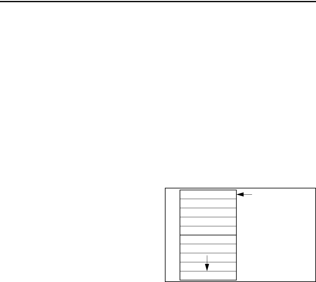
SECURE COMMUNICATION (ENCRYPTION)
65
necessary. It is no longer necessary to periodically
travel to the radio location or bring the radio into a
maintenance facility to load new keys.
The actual OTAR rekeying functions are
performed by a Key Management Facility (KMF) that
sends Key Management Messages (KMM) to the
radios. These messages are themselves encrypted
using a unique key. Radios must be OTAR-compatible
and programmed for OTAR for this type of rekeying to
occur.
Currently, OTAR is available only on P25
conventional channels, and to program DES-OFB and
AES keys (future programming on P25 trunked chan-
nels is planned). It is not used on SMARTNET/Smart-
Zone channels or to load DES/DES-XL keys.
10.4.2 ENCRYPTION KEY TYPES
There are two types of keys used with OTAR:
TEK (Traffic Encryption Key) - The key used to
encrypt voice and data traffic. All radios using encryp-
tion must have at least one of these keys. This is also
another name for the keys used without OTAR.
KEK (Key Encryption Key) - The key used to
encrypt keys contained in OTAR Key Management
Messages (KMMs). All radios which use OTAR must
contain at least one of these keys. The KEK used to
decrypt/encrypt keys in an OTAR message is defined
by the algorithm and key IDs transmitted in the
decryption instructions field. A KEK may be unique to
a particular radio (UKEK) or common to a group of
radios (CKEK).
10.4.3 KEYSETS
To simplify key management, a number of keys
may be grouped together in a keyset. A keyset is
simply a set of one or more keys of the same type
(either TEK or KEK). Keysets are identified by Keyset
IDs, and the upper four bits of this ID specify the
crypto group (see next section).
The KEK keyset is considered always active and
is ID 255. Two TEK keysets are normally used, and
one is always active and the other inactive. This allows
the inactive keyset to be replaced without interrupting
operation. One is Keyset ID 1 and the other Keyset ID
2. With EFJohnson radios, each keyset can contain up
to 128 keys, but less than 16 are normally used for
optimum keying efficiency and because only up to 16
can be selected by the radio.
The active keyset is usually selected by the Key
Management Facility. It can also be selected by the
keyloader function of the EFJohnson SMA
(Subscriber Management Assistant) or by the user if
the Change Keyset option switch or menu parameter is
programmed. Automatic keyset changeovers are not
supported by EFJohnson radios. In the SLN mode (see
Section 10.2.3), two TEK keysets can be used if
desired even if OTAR is not used.
A diagram of a keyset is shown in Figure 10-2.
Some information may be optional as shown. The
41xx portable does not support or use the Update Item
and Time/Date parameters.
Figure 10-2 Keyset Diagram
10.4.4 CRYPTO GROUPS
A crypto group contains up to 16 keysets of the
same type of key, either TEK or KEK (see Section
10.4.2). However, only two keysets are typically used
as just described. Crypto groups are used to help
manage keys such as when a radio uses keys with
different active times or multiple algorithms.
Currently, only one crypto group is supported, and it is
always ID 0. As shown in Figure 10-3, the crypto
group ID is the upper four bits of both the SLN and
Keyset IDs.
10.4.5 KEY MANAGEMENT FACILITY
The Key Management Facility (KMF) provides
key management and OTAR functions to applicable
16-Bit Keyset ID
Algorithm ID
Update Item (Opt)
Time/Date (Opt)
Keyset Name (Opt)
Key 1
Key 2
Key 4096
(upper 4 bits are
Crypto Group)
SECURE COMMUNICATION (ENCRYPTION)
66
radios within the radio system. One of the main tasks
of the KMF is to maintain a data base of information
Figure 10-3 Encryption Parameter IDs
contained in each radio. This information may include
the following:
•TEKs (main Traffic Encryption Keys)
•KEKs (Key Encryption Keys) used to encrypt
OTAR messages
•Keysets (groups of TEKs or KEKs)
•Crypto groups (groups of keysets)
•Cryptonets (groups of radios using same keys)
•Individual and group Radio Set Identifiers (RSIs)
•List of probable lost or stolen radios
The KMF performs OTAR functions by
exchanging Key Management Messages (KMMs) with
the radios. Both the KMF and radio can originate
messages. Some functions performed by the KMF are
as follows:
•Loading new keys
•Modifying keys
•Initiating keyset switch overs
•Modifying keyset attributes
•Deleting one or more keys to remove a radio from a
cryptonet)
•Deleting all keys (zeroize) when a radio may be lost
or compromised
•Determining if a radio is on the air and reading key
information
•Changing individual and group RSIs
10.4.6 MESSAGE NUMBER PERIOD (MNP)
One of the parameters that is programmed in a
radio utilizing OTAR is Message Number Period
(MNP). This parameter is programmed as described in
Section 10.5.2. This parameter is used to minimize the
possibility of someone sending messages to “spoof”
the system. The MNP is used as follows.
Every message sent out has a message number.
The message number increments by one with each
message sent. The MNP is the maximum difference
allowed between messages. For example, if the MNP
is set to 1000 and the last message number received by
the radio is different by more than 1000 from the
current message number, the current message is
ignored. If the MNP is set to 65535, message numbers
are ignored.
When determining this number, consider the like-
lihood of someone trying to spoof the system by
retransmitting recorded messages and then adjust the
MNP accordingly. The higher the risk, the smaller the
MNP should be. A disadvantage of setting a low MNP
is that the chance of blocking out intended messages
becomes higher. In addition, traffic level and terrain
contribute to lost messages and should also be consid-
ered when selecting this number.
A setting of 1000 is a good compromise because
it blocks out real old messages but is unlikely to affect
anything intentionally sent out by the system (1000
messages sent to a single radio is not likely to occur in
a system in less than a year with normal usage).
10.4.7 DEFINITIONS
Algorithm - Refers to the specific encryption standard
(DES or AES) that is used to encrypt a message. Each
standard uses different calculations to perform the
encryption (see Section 10.1.2).
Algorithm ID (ALGID) - Identifies the algorithm
(DES or AES) used to encrypt a message. This ID and
the Key ID are transmitted with each message to
uniquely identify the key being used.
Black - Refers to information that is encrypted. The
opposite is “Red” which refers to unencrypted infor-
mation.
Common Key Encryption Key (CKEK) - This is a
KEK common to a group of subscriber units which
share the same encryption keys (are part of same
crypto group). These keys can be the DES or AES
Crypto Group ID
(4-Bit = 0-15/0-F)
Keyset ID
8-Bit = 0-255/0-FF
xxxx xxxx
xxxx
SLN/CKR ID
16-Bit = 0-65535/0-FFFF
xxxx xxxxxxxxxxxx

SECURE COMMUNICATION (ENCRYPTION)
67
type. The use of a common key allows the subscriber
units to be rekeyed by the KMF using one Key
Management Message. Refer to “KEK” for more
information.
Common Key Reference (CKR) Group - Same as
Storage Location Number (SLN).
Crypto Group - A group of up to 16 keysets
containing the same type of keys (either TEK or
KEK). Although a crypto group can contain up to 16
keysets, only two are normally used. Only one keyset
in a crypto group is active at a time. EFJohnson radios
currently support only one crypto group.
Cryptographic Variable - The variable used by a
cryptographic algorithm to encrypt a message. Also
called a “key”.
Currency - Relates to the need for key updates. If a
subscriber unit is current, it does not require a key
update at the current time. If it is not current, the KMF
has new keys for that subscriber unit or CKR group
have not been sent or have been sent but not acknowl-
edged.
Group Rekeying - The process of changing the keys
in several subscriber units with a single message
addressed to the group rather than changing each
subscriber unit separately. This addressing is done
using a group RSI. Group rekeying reduces system
overhead and makes rekeying more efficient.
Subscriber units in the same group must be
programmed with a common KEK (CKEK) and use
the same TEKs.
Key - A variable used by a cryptographic algorithm to
encrypt voice or data. Also called “Cryptographic
Variable”.
Key Encryption Key (KEK) - A key used to encrypt
keys contained in Key Management Messages
(KMMs) during OTAR. These messages may them-
selves be encrypted by the currently active TEK.
These keys can be the AES or DES type. There are
KEKs unique to a subscriber unit (UKEK) and
common to a group (CKEK). The other type of key is
the Traffic Encryption Key (TEK) used to encrypt
voice and data messages.
Key ID - This is a 16-bit (four hex digit) number iden-
tifier from 1-65535 for an encryption key which
allows the key to be identified without revealing the
actual key variable. This ID and the Algorithm ID
uniquely identify a key within the KMF or subscriber
unit. Therefore, two keys can have the same ID if they
have different algorithm IDs and vice versa. The Key
ID and Algorithm ID are usually transmitted with a
message to identify the key that must be used to
decrypt it. Key ID 0 is not used with OTAR.
Key Management Facility (KMF) - The equipment
and software which provide OTAR and related key
management services to the subscriber units.
Key Management Message (KMM) - These are the
messages composed by the KMF to send encryption
information to subscriber units via the keyloader or
OTAR. KMMs are themselves encrypted using two
layers of encryption: inner and outer. The inner layer
of encryption is the KEK and the outer layer is the
TEK. At this layer, the KMMs are also included in a
Common Air Interface (CAI) message which adds
another layer of addressing. In addition, a Message
Authentication Code (MAC) is used.
Keyset - A group of keys of the same type (KEK or
TEK) that are managed as a single entity (they can be
updated, deleted, and rekeyed with a single
command).
Keyset Changeover - The process used to switch a
subscriber unit to another keyset so that the unused
keyset can be replaced without interrupting encrypted
communication.
Key Loader - Any type of device used to load encryp-
tion keys into a radio. With OTAR, this device must be
used to provide the initial key loading of a subscriber
unit so that it contains the basic keys needed for
OTAR by the KMF. If OTAR is not utilized, is always
used to load encryption keys. All keys stored in the
key loader are themselves encrypted. EFJohnson
offers a PDA-based keyloader.
Logical Link ID (LLID) - An ID transmitted with a
data message to identify the destination of the
message.

SECURE COMMUNICATION (ENCRYPTION)
68
Message Number Period (MNP) - The maximum
difference between message numbers that can occur
before a message is declared invalid (see Section
10.4.6).
Over-The-Air-Rekeying (OTAR) - The process of
sending new encryption keys over the air using an RF
interface.
Red - Refers to information that is not encrypted. The
opposite is “Black”.
Rekey - The process of preparing, sending, and
loading encryption keys into a subscriber unit for
current or future use. This may be done over-the-air
(OTAR) or by directly connecting a keyloader to the
subscriber unit.
Radio Set Identifier (RSI) - Subscriber units are
programmed with one or more Radio Set Identifier
(RSI) numbers that identify the unit for OTAR
purposes. The RSI can be unique to a individual
subscriber unit or unique to a group of subscriber
units. An individual (unit) RSI is always assigned and
one or more group RSIs may be assigned. The indi-
vidual RSI is typically programmed when the
subscriber unit is initially brought into service. The
KMF is also identified by an RSI (KMFRSI) to use as
the destination of any KMMs a subscriber unit origi-
nates. The KMMs (Key Management Messages)
generated by the KMF (Key Management Facility) are
addressed to a specific RSI.
Storage Location Number (SLN) - A link to a
specific key (TEK or KEK) in the active keyset. The
SLN specifies both a crypto group and a key within
the keysets in that crypto group (the first four bits of
the SLN are the crypto group ID). SLNs and CKRs are
equivalent terms (see Section 10.2).
Traffic Encryption Key (TEK) - A key used to
encrypt voice or data. The other type of key is the Key
Encryption Key (KEK) which is used to encrypt keys
contained in Key Management Messages. TEKs can
be either the AES or DES type.
Unique Key Encryption Key (UKEK) - A KEK
unique to a particular subscriber unit. Refer to “KEK”
for more information. These keys can be either the
AES or DES type.
Zeroize - The process of deleting all keys from a
compromised subscriber unit to disable it. To make the
unit functional again, the keys must be reloaded by a
keyloader.
10.5 RADIO SETUP FOR ENCRYPTION
10.5.1 GENERAL ENCRYPTION SETUP
The following radio setup is required for encryp-
tion regardless of whether OTAR is used:
Options Enabled - The desired encryption type must
have been enabled at the factory (DES, DES-XL,
DES-OFB, AES). To determine what options are
enabled, using the PCConfigure programming soft-
ware, select the Transfer > Read Options From Radio
menu parameter.
PCConfigure Programming
PID/SLN Mode - On the global screen, select
either the PID or SLN mode (see Section 10.2.3).
If the SLN mode is used, also program the Keys
Table by clicking the button.
Infinite Key Retention - On the global screen,
select this parameter to store keys permanently
in memory (see Section 10.2.4).
Erase Keys On Keyset Change - On the global
screen, if the SLN mode is selected and more
than one keyset is used (see Section 10.4.3),
select this parameter to erase keys when
changing keysets (see Section 10.2.6).
Program Channel/Group PIDs and Encryption
Type - With conventional analog calls, this infor-
mation is programmed on the channel screen.
With other types, it is programmed in the talk
group list selected on the system screen. In addi-
tion, with conventional digital calls, the group
programming can be overridden on the channel
screen (see Section 10.3.3). Additional PIDs for
special calls can also be specified on the system
screen for digital and trunked calls. NOTE: The
encryption type is not selectable on digital chan-
nels because the AES/DES mode is determined
by the key type loaded, not by PCConfigure
programming.

SECURE COMMUNICATION (ENCRYPTION)
69
Currently, EFJohnson 41xx portables and 43xx
mobiles that meet the following requirements support
OTAR:
Programming - An RSI and UKEK and other infor-
mation must be programmed as described in the next
section.
10.5.2 ADDITIONAL SETUP FOR OTAR
Additional PCConfigure Programming For OTAR
The following parameters must be programmed
for OTAR operation in addition to those in Section
10.5.1 .
1. On the Radio Wide Conventional screen, program
the Digital Unit and Unit RSI IDs. The Unit RSI
ID can be set to the Digital Unit ID only, but later
can be changed by the KMF or keyloader if desired.
Note these two numbers.
2. On the Per System Conventional screen, select
OTAR Enabled = On and Data Registration
Enabled = On. When data registration is enabled,
the radio registers with the data system on a channel
change.
3. Also on the Per System Conventional screen, set the
OTAR Time Out Time. When rekeying is
requested by the radio (OTAR Rekey option button
pressed or menu selected), this setting determines
how long the radio waits for a response from the
KMF. Times of 20-180 seconds can be programmed,
and the default is 30 seconds.
Motorola RNC Registration (If Required)
The 41xx portable does not support Motorola
dynamic data registration. Therefore, each radio must
be manually registered on the Motorola RNC Console
by entering the following command:
LCRD 03 06 00 1234 7F xx xx xx 0A 0A 00 07 00 yy
Where, “xx xx xx” is the hex value of the Digital
Unit ID entered by the PCConfigure software. Refer to
the console documentation for the value of “yy” or use
“00”. This registration needs to be done only once.
Programming By Keyloader
The following are the minimum parameters that
need to be programmed in the radio to perform OTAR.
It is not necessary to program a TEK to perform
OTAR. If the radio does not contain a TEK, the KMF
initiates a warm start-up sequence in which a tempo-
rary TEK is transferred to the radio to perform the key
transfer.
1. UKEK - This key normally has SLN (CKR) 61440
and Key ID 62880 (F5A0 hex). Create a key (either
AES or DES type as required) and download it to
the radio.
2. RSI - This is normally initially the same as the P25
Unit ID and is programmed by the PCConfigure
software as described in Section 10.5.1. Therefore,
the RSI should not need to be loaded if it is the first
time the radio is being set up for OTAR or if the
radio dumps keys due to long-term battery discon-
nect. However, it may need to be loaded if the radio
is manually deleted from the KMF and then recre-
ated since the message number must be reset to 0
(the Load Target RSI command resets the message
number to 0).
3. KMF RSI - This RSI is normally 9,999,999 and
should not need to be loaded since it defaults to this
number.
4. MNP (Message Number Period) - Load the proper
message number period into the radio (typically
1000). Refer to Section 10.4.6 for more information.
5. Verify that the above information was properly
stored in the radio by viewing it using the keyloader.
10.6 RADIO OTAR CAPABILITIES
10.6.1 SEM 4100/53XX, STANDARD 41XX
The OTAR capabilities of the SEM equipped
4100 portable and 4300 mobile are as follows.
Keysets
•Up to three keysets are used and it is assumed all
three are always present.Keyset IDs 1 and 2 are for

SECURE COMMUNICATION (ENCRYPTION)
70
TEKs and only one is active at a time. Keyset ID 255
is for KEKs and is considered active all the time
•Each keyset can have up to 128 keys. However, 16
or less are normally used.
•AES encryption is supported (with Flash code 1.8.0
or later) but not currently available with OTAR
(future availability is planned).
RSI (Radio Set Identifier)
•One individual RSI and it is usually initially the
same as the P25 Unit ID.
•One group RSI (usually initially “0”).
•One KMF RSI (usually always 9,999,999).
OTAR Messages That Are Supported
The following KMM Message IDs are recognized
by or sent:
CHANGE RSI 0x03
CHANGE RSI RESPONSE 0x04
KEYSET CHANGEOVER 0x05
KEYSET CHANGEOVER RESPONSE 0x06
DELAYED ACK 0x07
HELLO 0x0C
INVENTORY 0x0D
INVENTORY RESPONSE 0x0E
MODIFY KEY 0x13
MODIFY KEYSET ATTRIBUTES 0x14
MODIFY KEYSET ATTRIBUTES RESPONSE0x15
NEGATIVE ACK 0x16
NO SERVICE 0x17
REKEY ACK 0x1D
REKEY 0x1E
WARM START 0x20
ZEROIZE 0x21
ZEROIZE RESPONSE 0x22
10.6.2 UCM EQUIPPED 4100
The 41xx UCM version uses the Motorola UCM
encryption module. Therefore, the OTAR capabilities
are determined by that module. All capabilities of the
Motorola KVL and KMF are supported. Initial radio
programming by the PCConfigure software is the
same as described in
Section 10.5.
10.6.3 OTAR OPTION SWITCHES
The following additional option switches can be
programmed with the 4100 portable and 4300 mobile
to control OTAR functions. They are also available as
4100 menu parameters unless noted otherwise.
Change Keyset - Toggles the active keyset between
Keyset 1 and Keyset 2. The new active keyset is
briefly displayed and then normal operation resumes.
When the 4100 menu is used, the current active keyset
is indicated by an asterisk. To change to the other
keyset, highlight it and press the F2 key.
Clear/Secure Select - This enables and disables
encryption regardless of whether OTAR is used. Refer
to Section 10.3 for more information.
Erase Keys - Erases all TEK and KEK keys contained
in the radio. With the 4100, this function is available
as menu parameter only.
Key Select - This allows a different key to be selected
for the current channel or group (conventional chan-
nels only). Refer to Section 10.2.5 for more
information.
OTAR Rekey Request - Sends a message which tells
the KMF that the radio is on the air and requests
rekeying. The following status messages are displayed
which indicate the progress of this function. Addi-
tional functions that are available when this is selected
using the 4100 menu mode are described in the next
section.
Rekeying - A radio-initiated rekeying session is in
process.
No Ack - No response was received from the KMF
in response to an Identify request before time out
occurred (approximately 30 seconds).
Ack Rcvd - An acknowledgement was received in
response to an Identify request.
No Service - A “No Service” reply was received
from the KMF. No rekeying will take place.

SECURE COMMUNICATION (ENCRYPTION)
71
Rekey Fail - Either the rekey command failed or
timed out (after approximately 30 seconds). This
message could indicate that the rekey request
message was not received by the KMF. However,
depending on the KMF configuration and channel
traffic, it is possible that the message was received
and a response is still pending.
Rekeyed! - The rekey session initiated by the radio
was successful.
Additional Functions Selectable by 4100 Menu:
(To select one a parameter, highlight it and press
F2.)
Rekey - Performs the same function as the OTAR
Rekey Request option switch described in the
preceding section.
Need KEK - Sends a request for a new KEK (Key
Encryption Key). Upon receiving this message, the
KMF marks the radio as requiring service. One time
this function may be selected is if the radio dumps it
keys.
Identify - Sends a message which tells the KMF that
the radio is on the air. Currently, the KMF always
responds with “No Service”, even if the keys are not
up to date. If “No Ack” is displayed, the KMF may
not have received the message (see preceding
section). This function can be used to test communi-
cation without initiating the rekeying that occurs
with the preceding “Rekey” function.
Erase Keys - Erases all keys in the radio the same as
the Erase Keys option switch described in the
preceding section.

74
INDEX
INDEX
A
Accessory Connector 12
AES Encryption 61
Alert Tones 22
Algorithm 66
Algorithm ID 66
Analog and Digital Operation 42
ANI Signaling 33
Antenna Connector 11
Autodetect 64
B
Backlight 16
Battery 12
Battery Charging 16
Battery Saver Feature 16
Black 66
Busy Indicator 27
Busy Override 50
C
Call Alert 46
Call Alert (P25 Conv) 37
Call Guard Squelch 28
Channel Select 14
Channel Switch 11
Channels 18
CKEK 66
CKR 67
Clear/Secure Strapping 63
Clone Feature 34
Conventional Mode 17
Conversation Timer 29
Crypto Graphic Variable 67
Crypto Group 65, 67
CTCSS/DCS Signaling 28
Currency 67
D
Delay, Scan Resume 23
DES-OFB 61
DES-XL 61
Determining Available Options 57
Direct Channel Selection 14
Display 12
DTMF Keypad 11
Dynamic Regrouping 50
E
Emergency Alarms (Conv) 30
Emergency Alarms (SN/SZ) 48
Emergency Calls 48
Emergency Calls (Conv) 31
Emergency Hot Mic 31, 48
Emergency Man-DOwn Feature 49
Encryption 61
Encryption Key 62
Encryption Key Select 63
Encryption Keys 62
Enhanced Private Conversation
Mode 43
Extended Range Operation 56
F
F1 Key 10
F2 Key 10
F3, F4 10
Facility 65
Failsoft Operation 49
Features
Conventional 8
General 8
P25 Trunked 9
Project 25 35
Project 25 Trunked 9, 42
SMARTNET/SmartZone 8
SmartZone 50
FIPS 140-2 61
Frequency Display 30
Front Display 10
G
Group Calls 42
P25 35
Group ID Code 35
Group Rekeying 67
H
Home Zone Select 22
Hot Mic 31, 48
I
Indicator
Priority Channel 32
Top Panel 11
Individual Calls 35
Infinite Key Retention 16, 63
K
KEK 67
Key 67
Key Encryption Key 65
Key Erase Menu Parameter 63
Key ID 62, 67
Key Loader 67
Key Management Facility 65
Keypad Lock 16
Permanent 16
Keypad Programming 38
Keyset 65, 67
KMF 67
KMM 67
L
Licensing 56
Lookback Time 32
Lost Passwords 59
Low Battery Indicator 15
M
Man-DOwn Feature 31
Master Radio 34
Menu Mode 20
Menu Mode Functions 21
Message Number Period 68
Message Number Period (MNP) 66
Messaging 47
Messaging (Conv P25) 38
Microphone 10
Mode
Conventional 17
Project 25 Conv 17
Project 25 Trunked 18
SMARTNET/SmartZone 17
Monitor Mode 27
Monitoring Before Transmitting 27
N
NAC 35
Network Acess Code 35
Nuisance Channel Delete 24
O
On-Off/Volume Control 11
Operating Modes 17
Option Button
Key Select 63
Option Switch 11
Alert Tones 22
Backlight 16
Call Alert 37, 47
Call Response 45
Change Keyset 70
Channel Select 14, 15
Clear/Secure 42, 70
Digital Talk Group Select 35
Display Information 30
Emergency 11, 30, 31, 48
Erase Keys 70

INDEX
75
High/Low Power 22
Home 22
Key Select 63, 70
Keypad Lock 16
Keypad Programming 39
Message 38, 47
Monitor Mode 27
Normal/Selective 28
OTAR Rekey Request 70
P25 Packet Data 38
Phone 37, 45
Priority Select 33
Private Call 43, 44, 45
Private Call (SmartNet) 43, 44, 46
Radio Wide Scan 23
Repeater Talk-Around 30
RWS List Edit 26
Scan 23
Scan List Edit 25
Scan List Select 25
Selective Squelch 29
Set User Password 14, 59
Single Tone Encoder 33
Site Lock 51
Site Search 51
Squelch Select List 29
Status 38, 47
Surveillance Mode 22
Talk Group Select 35
Tone Volume 22
Unit Call 36, 37
Volume Up/Down 13
Option Switch Functions 21
Option Switches 20
Option Upgrading 57
Optional Features 57
OTAR 68
OTAR Definitions 64
OTAR Messages Supported 70
P
P25 Packet Data 38
Paging 37, 46
Answering 46
Answering (Conv P25) 37
Initiating 37, 47
Password
Changing 59
Download/Upload 59, 60
Master 59, 60
Operation 59
Power On 59, 60
Power-Up 13
User 59, 60
Zone 60
Penalty Timer 29
PID Mode 62
Power On-Off 13
Power Output Select 22
Power Up Sequence 13
Power-Up Password 13
Priority Channel
Changing 33
Priority Sampling
Conv 32
P25 Trunked 49
SMARTNET/SmartZone 49
Programming 55
Project 25
Group ID Code 35
Unit Calls 35
Unit ID 35
Project 25 Mode 18, 35
PTT ID 43
PTT Switch 11
R
Radio Options Screen 58
Radio Set Identifier 68
Radio Wide Mode Scan List 26
Radio Wide Scan 23
Receive Only 17
Red 68
Rekey 68
Repeater Talk-Around 30
RS-232 Port 38
RSI 68
RW Scan List
Determining Channels in 26
Editing 26
S
Scan Hold Time 23
Scan List 24
Channel Delete 24
Determining Channels in 24
Editing 25
Selecting 25
Scanning 23
Conv 31
P25 Trunked 49
Priority 23
Radio Wide 23
SMARTNET/SmartZone 49
Secure Communication 61
SecureNet 61
Servicing 56
Silent Mode 30
Single Tone Encoder 33
Site ID (SmartZone) 51
Site Locking/Unlocking 51
Site Trunking 50
Slave Radio 34
SLN Mode 62
SMARTNET/SmartZone Mode 17
Soft Power Down 13
Speaker 11
Speaking Into Microphone 56
Squelch Adjust 17
Squelch Code Select 29
Squelch Control 17
Standard Calls
Placing (Conv) 33
Receiving (Conv) 33
Receiving (SMARTNET) 42
Standard Private Conversation
Mode 43
Status Messages 38, 47
Storage Location Number 68
Supervisory Tones 53
Surveillance Mode 22
Systems 18
T
TEK 68
Telephone Calls 45
Telephone Calls) 36, 45
TG on Rx 43
Time-Out Timer 20
Tone Select 22
Tones 53
Trademark Information 2
Traffic Encryption Key 65, 68
Transmit Disable 17
Transmit Disable On Busy 27
Transmit Type 41
Transmitting in Scan Mode 24, 32
Troubleshooting 56
U
Unit Calls
P25 35
Unit ID
Project 25 Conv 35
SMARTNET/SmartZone 42
Unit-To-Unit Calls 43
Up/Down Switch 10
User Group ID 43
V
Voice Encryption 61
Volume Adjust 13
Volume Control Disable 13
Volume Up/Down 13
W
Warranty 2
Wireless Cloning 34
Z
Zeroize 68
Zone Password 39, 60
Zone Select 11, 14
Zones 19

Part Number 002-4100-xxx x
12-04 Printed in U.S.A.