E F Johnson 2425112 5100 ES Series VHF Radio User Manual User operating manual 2
E. F. Johnson Company 5100 ES Series VHF Radio User operating manual 2
Contents
- 1. Manual
- 2. User operating manual
- 3. User operating manual 2
- 4. User operating manula 3
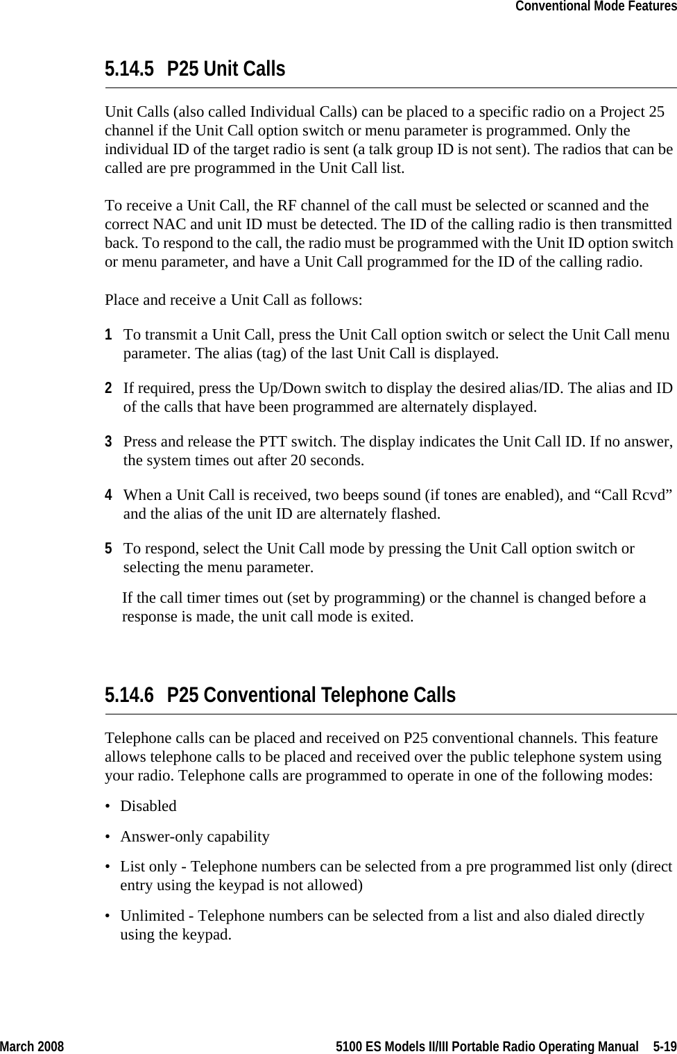
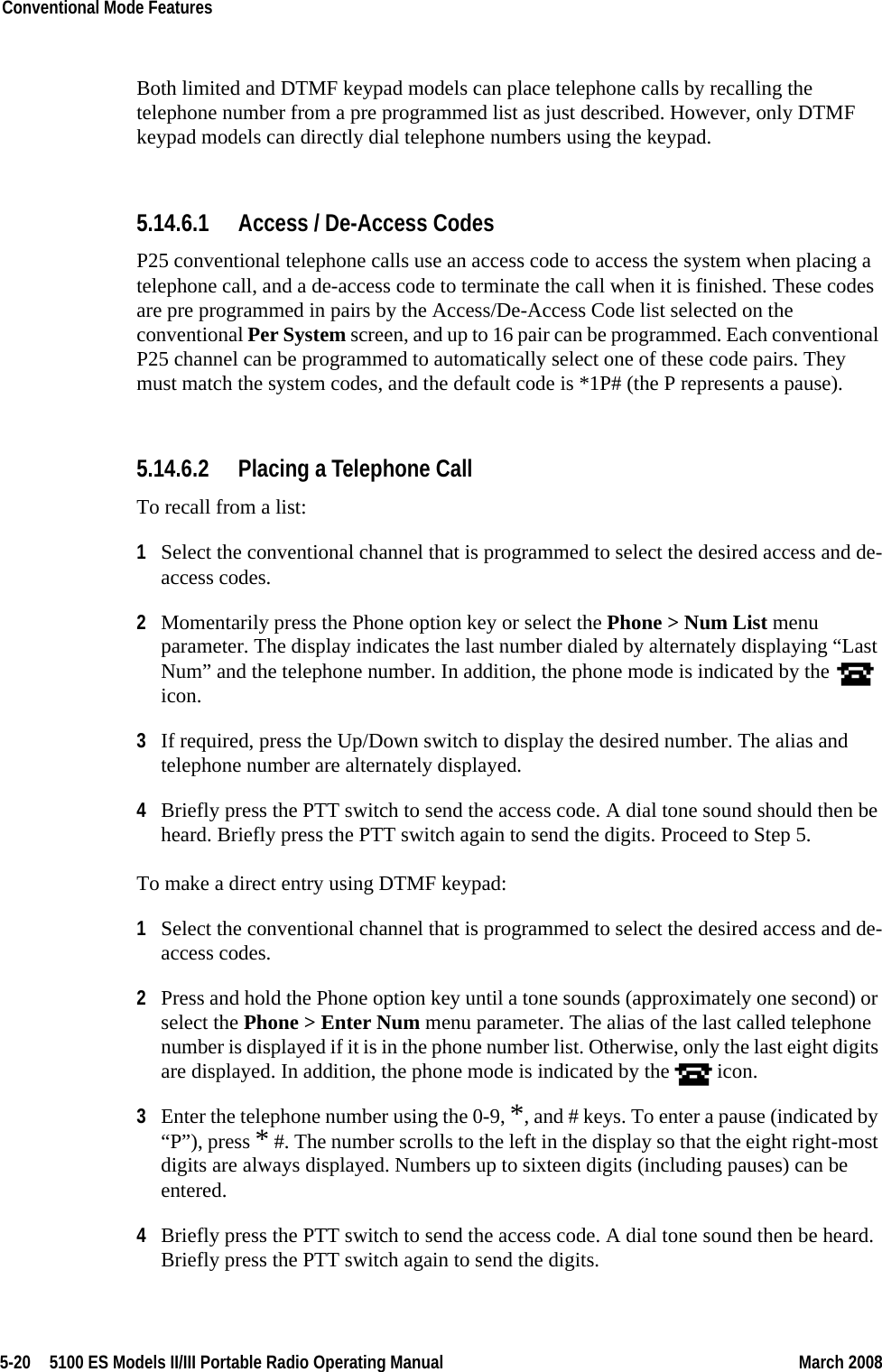
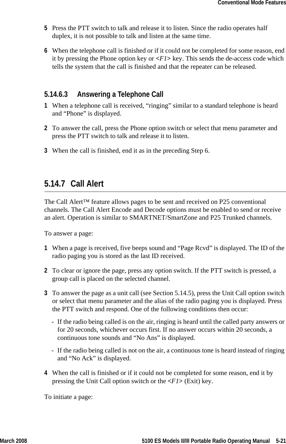
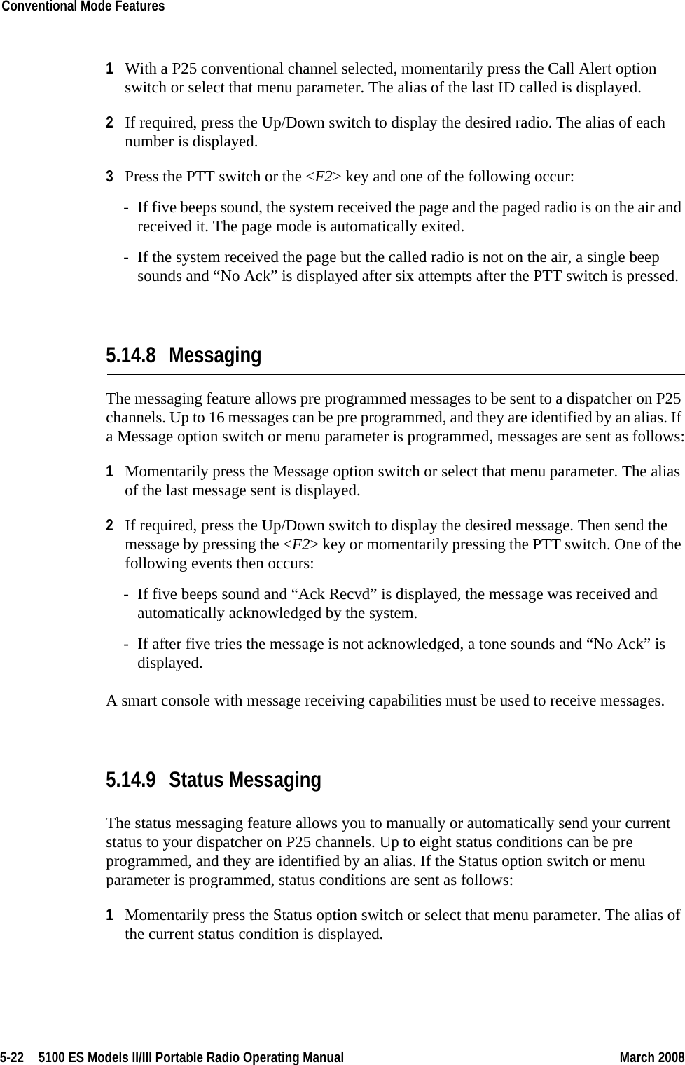
User operating manual 2
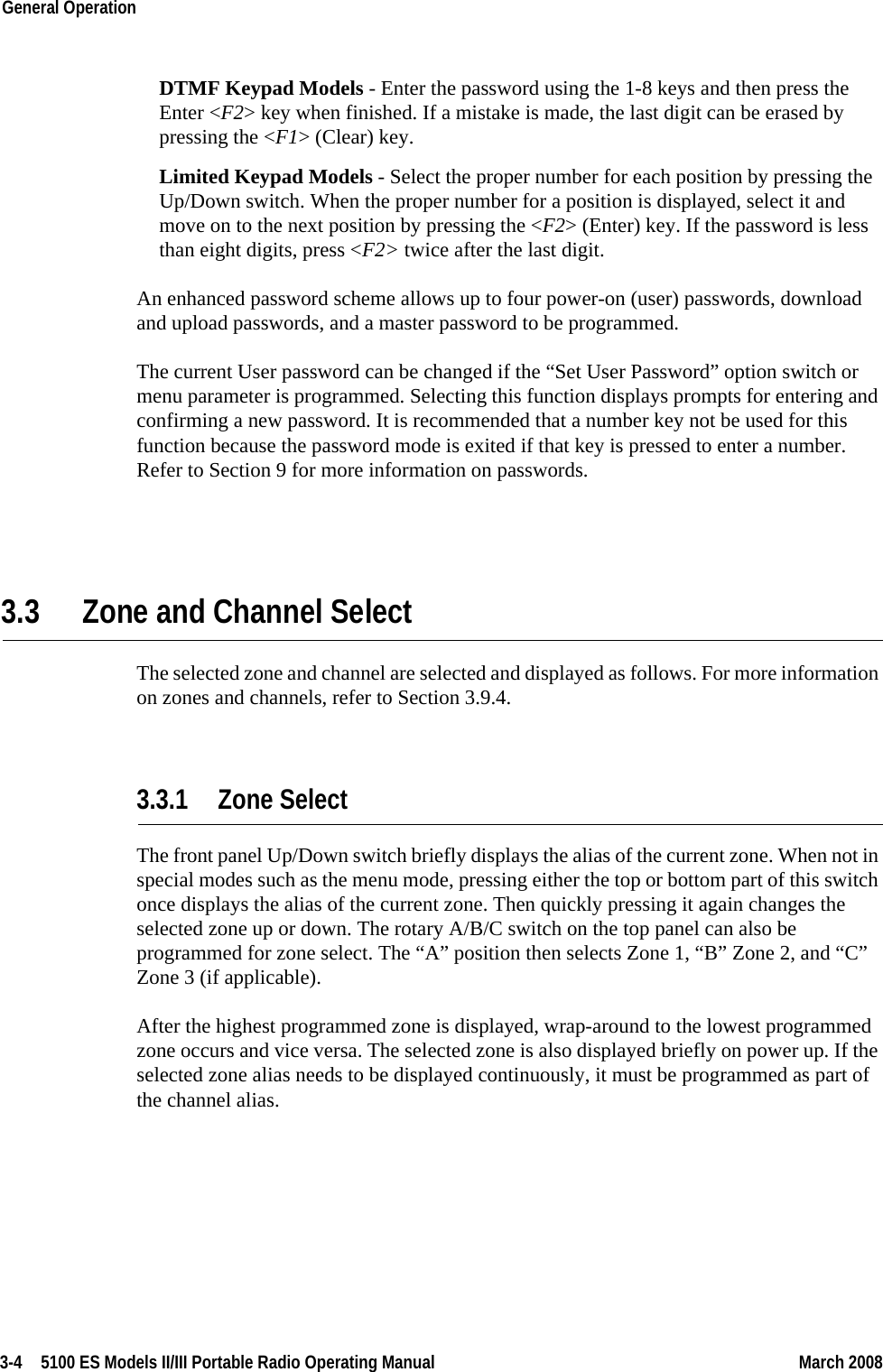
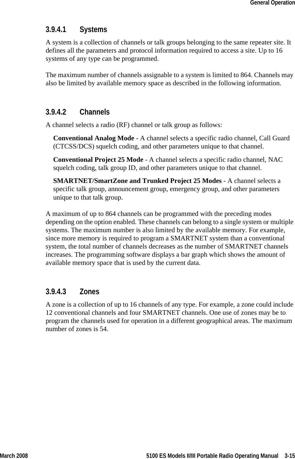
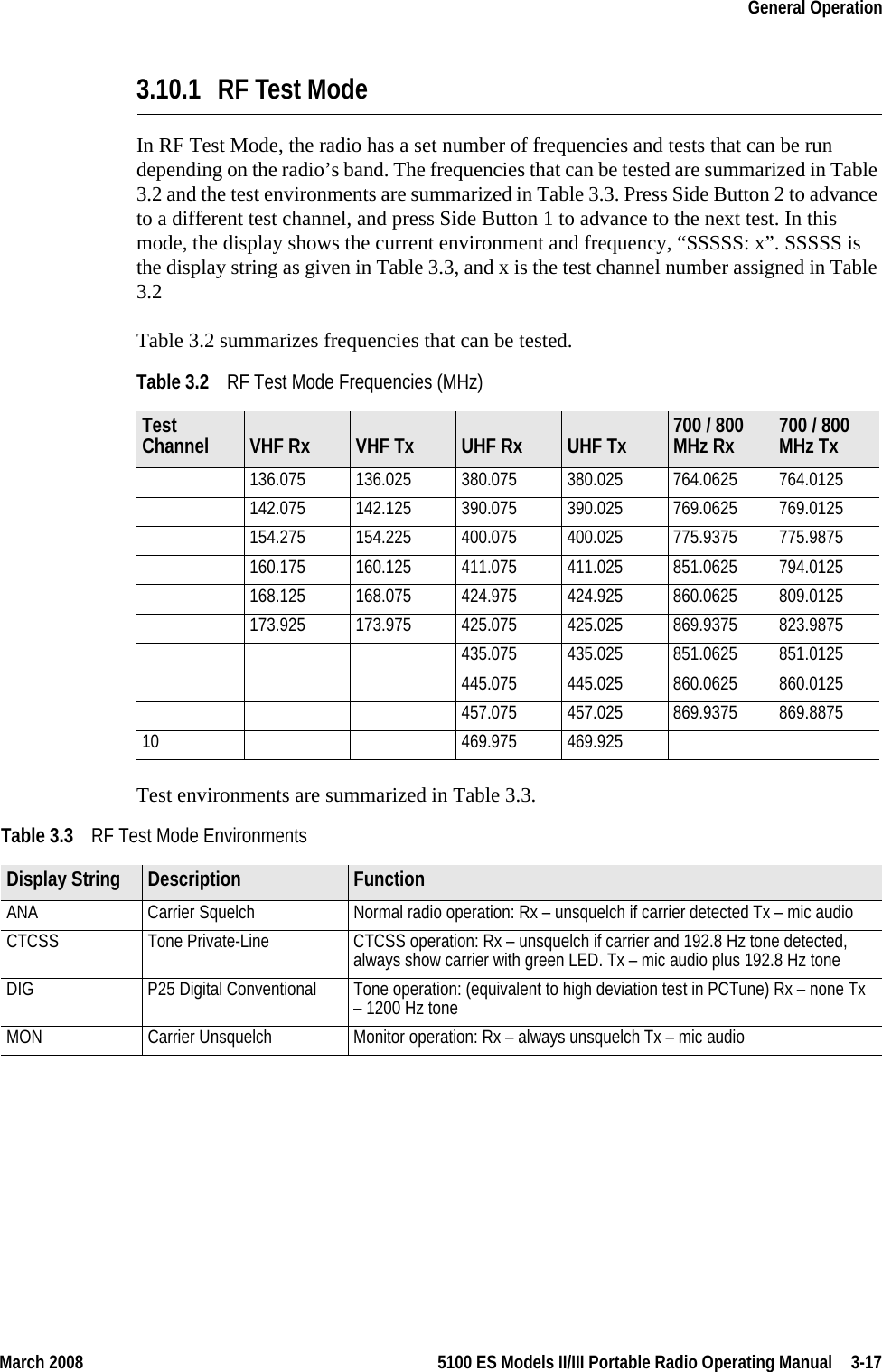
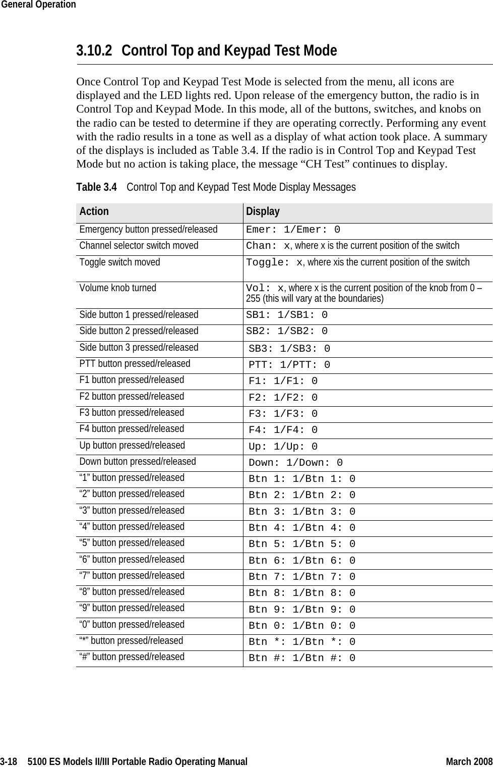
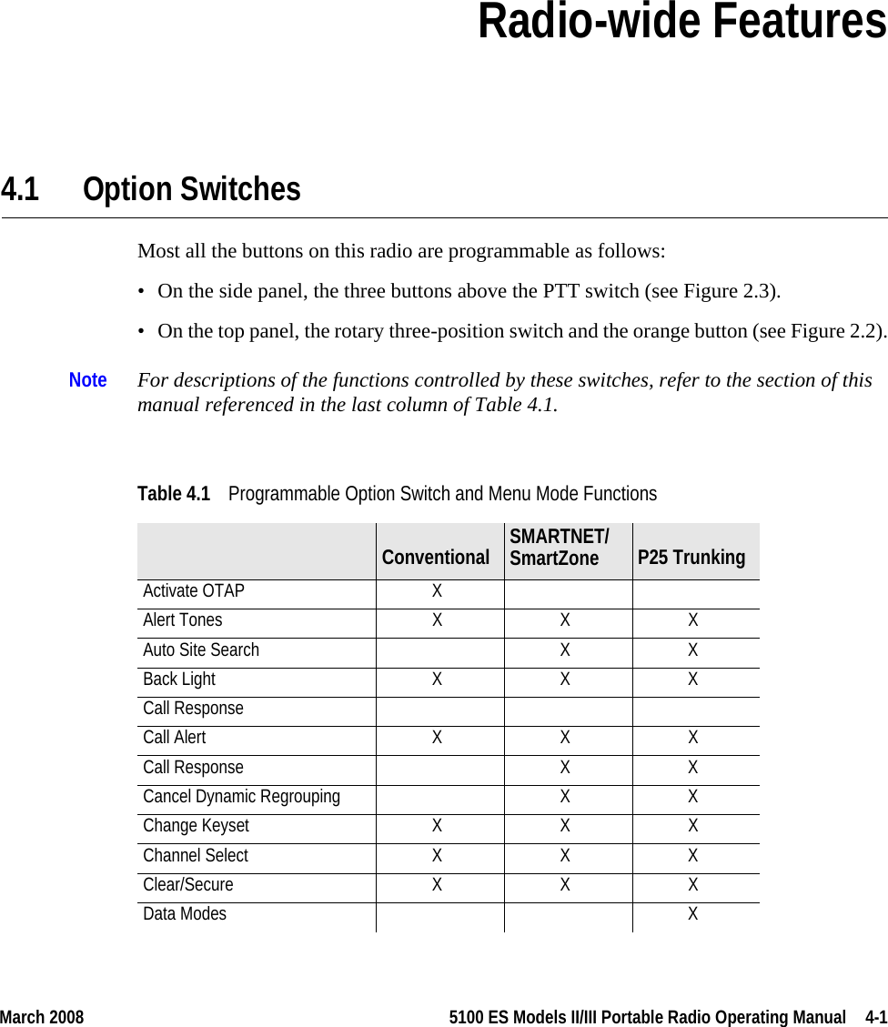
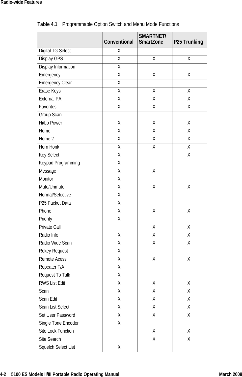
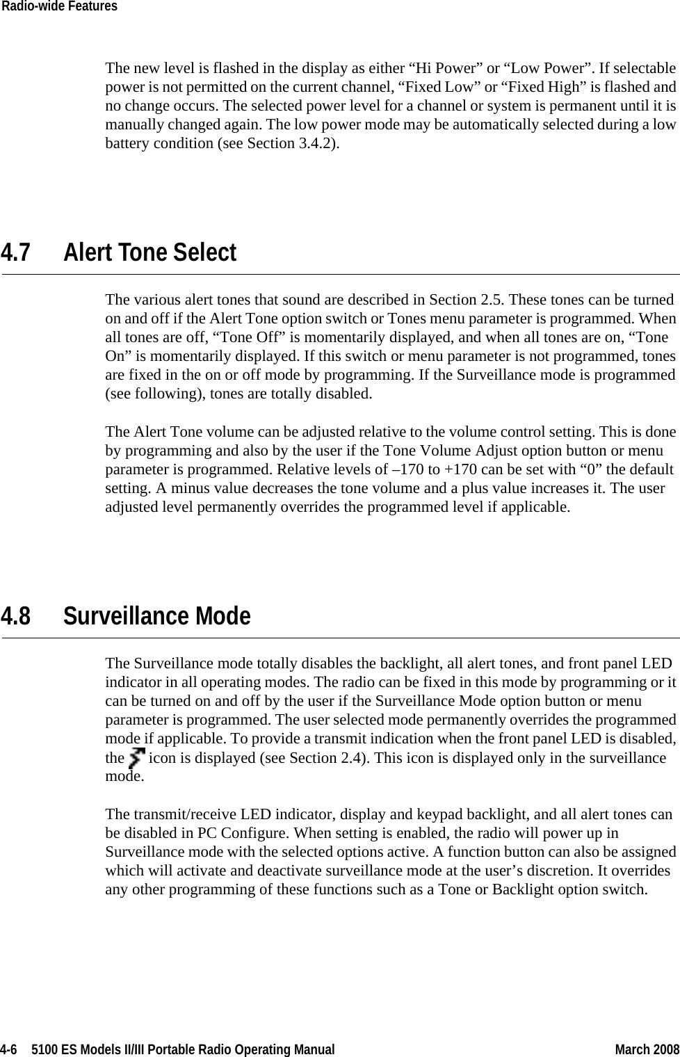
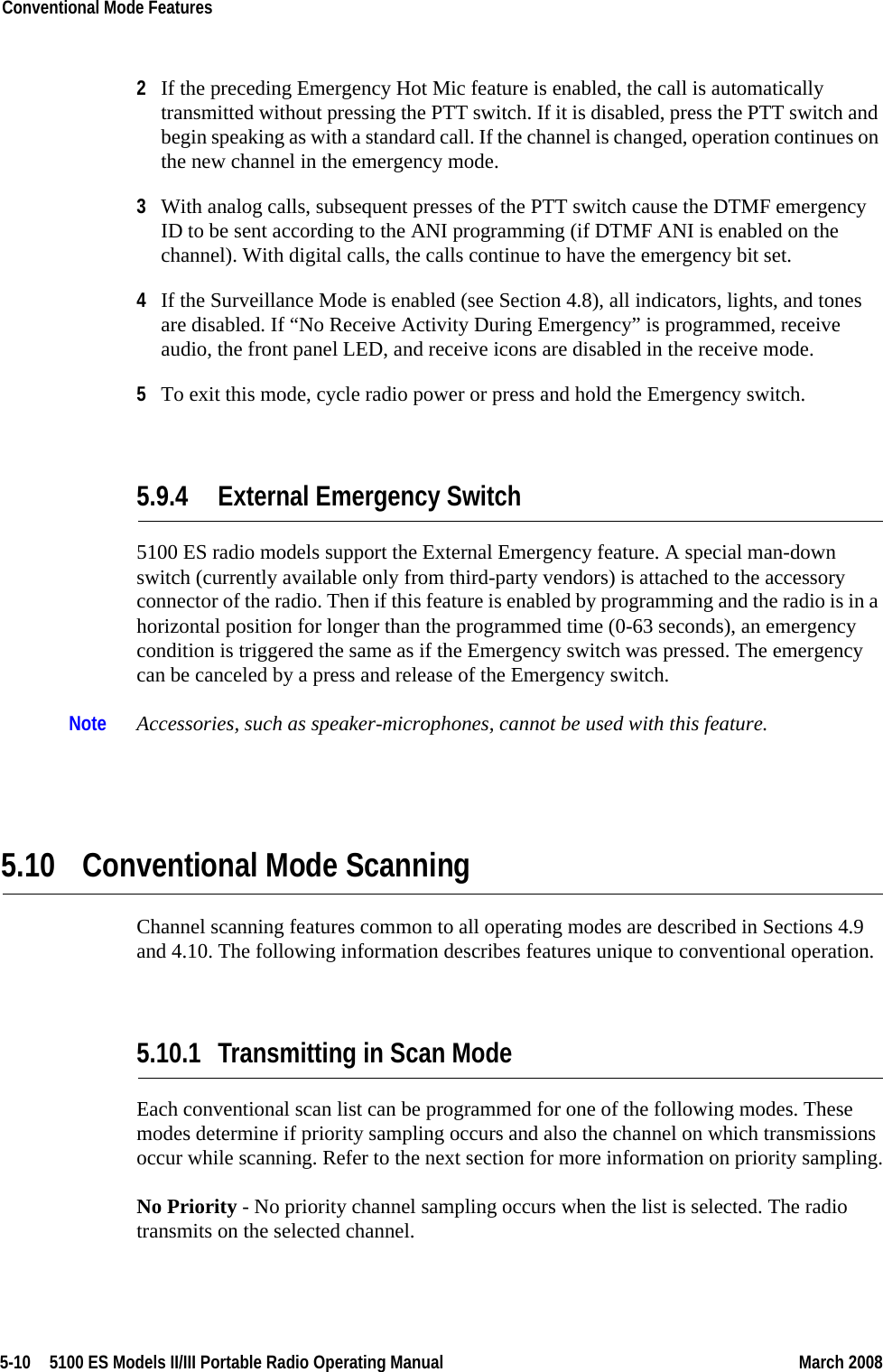
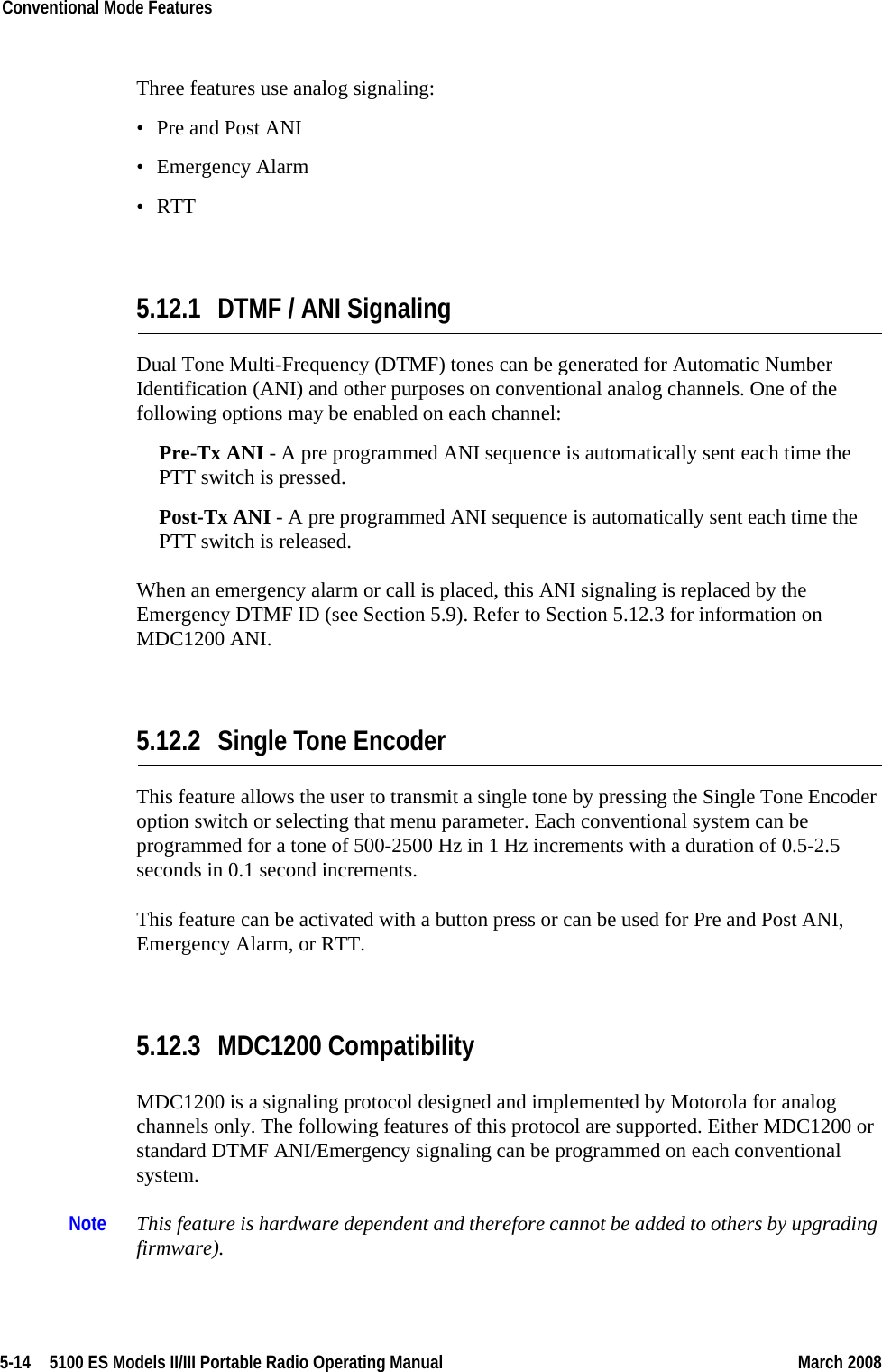
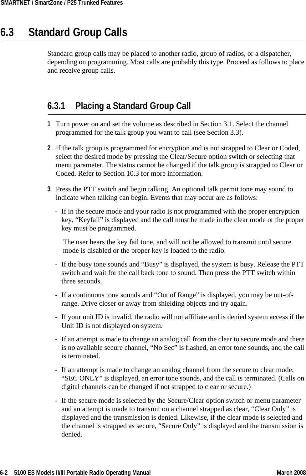
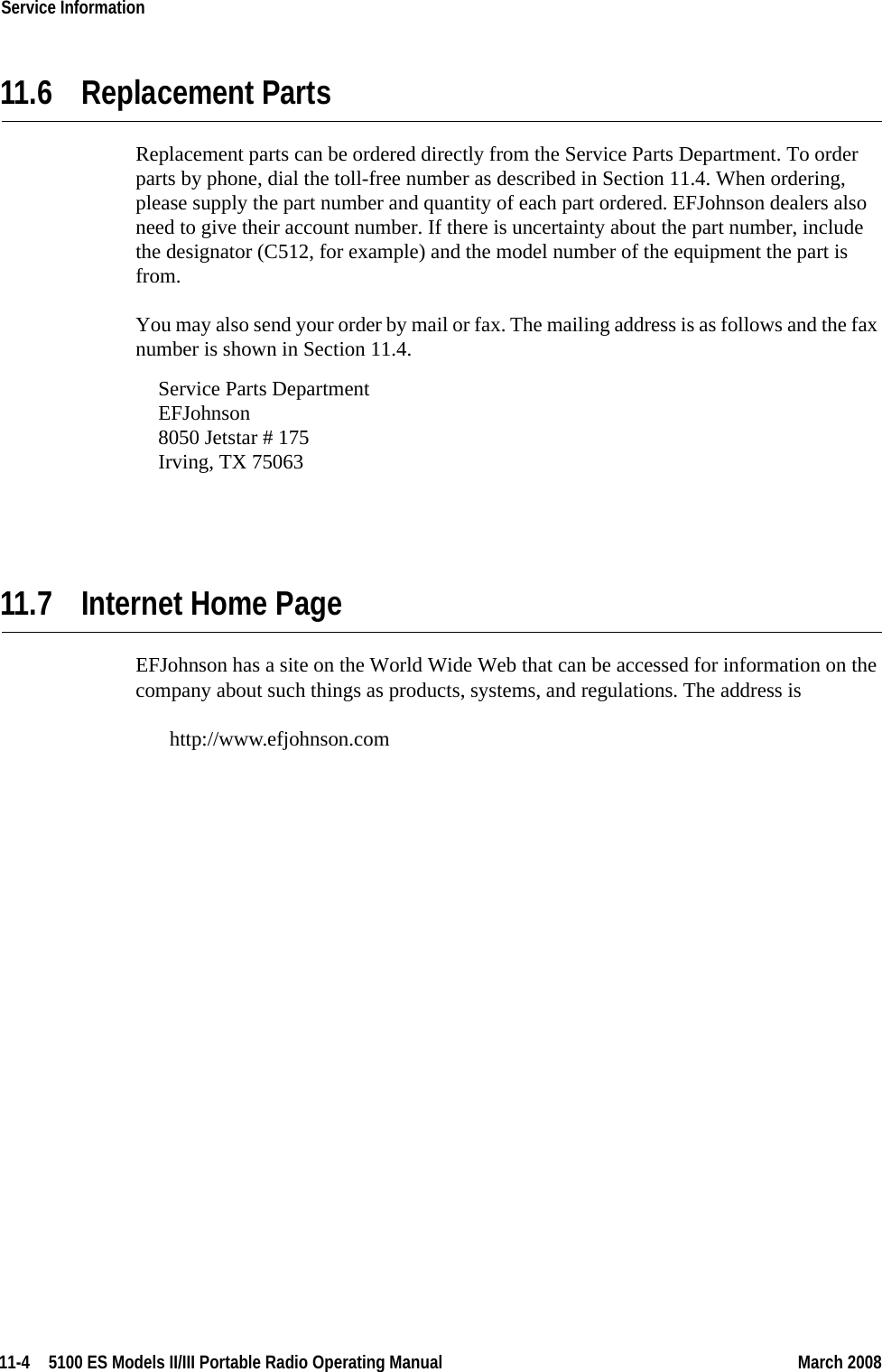
![3-16 5100 ES Models II/III Portable Radio Operating Manual March 2008General Operation 3.10 Radio Tune Test ModeThe Radio Tune Test function is used primarily by technical personnel. To enter Radio Tune Test Mode, press Side Button 2 during the interval between the initial display and the completion of the self test. Pressing Side Button 2 after the self test has completed has no noticeable effect on the radio other than its programmed functionality. I.e., if Side Button 2 is pressed after the self test has completed, the radio operates normally and Radio Tune Test Mode cannot be entered while the radio remains powered.After pressing Side Button 2 during the self test, the radio completes the self test and displays the message “Service”. The radio cycles through several informational displays, which are summarized in Table 3.1. To stop a display, press the Up Button. To continue displays, press the Down Button. To quickly cycle through the displays, continue to press the Down button. You cannot go back to displays that have already been shown.Upon completion of the information displays, the radio enters a menu mode. The default option is the RF Test Mode, and the message “RF Test” is displayed. Press Side Button 1 to cycle between the two modes, RF Test Mode and the Control Top and Keypad Test Mode (displaying “CH Test”), Press the Emergency Button to enter into the test mode that is currently displayed.Table 3.1 Initial Messages 5100 ES Description Service Test Tune Mode initial message Firmware Firmware display message V x.y.z Firmware version number DSP DSP display message V x.y.z DSP version number SEM SEM display message V x.y SEM version number File Form. File format display message V x.y File format version number Bootload Bootload display message V x.y Bootload version number ESN ESN display message xx-xx-xx-xx-xx-xx-xx-xx* ESN of the radio (in hexadecimal) Band Band display message [VHF, UHF, UHF High, UHF 380, 700/800, 800, 900] Band of the radio * Scrolling Message](https://usermanual.wiki/E-F-Johnson/2425112.User-operating-manual-2/User-Guide-942760-Page-16.png)