E F Johnson 2425112 5100 ES Series VHF Radio User Manual User operating manual
E. F. Johnson Company 5100 ES Series VHF Radio User operating manual
Contents
- 1. Manual
- 2. User operating manual
- 3. User operating manual 2
- 4. User operating manula 3
User operating manual

5100 ES Models II/III
Portable Radio
Operating Manual
VHF / UHF / 700/800 / 800 MHz
Project 25 Conventional and Trunked
Analog and Digital Conventional
SMARTNET®/SmartZone®
7.2 VDC
5 Watt (VHF), 4 Watt (UHF), 2.5 Watt (700 MHz), 3 Watt (800 MHz)
Part of Part Number 002-5100-70002CD
March 2008
Copyright © 2006 - 2008 by EFJohnson
The EFJohnson logo, PC Configure™, Trunked IP25™, and Call Guard® are trademarks of EFJohnson. All
other company and/or product names used in this manual are trademarks and/or registered trademarks of
their respective manufacturers.
Information in this manual is subject to change without notice.
5100 ES Models II/III Portable Radio Operating Manual
March 2008

March 2008 5100 ES Models II/III Portable Radio Operating Manual i
Table of Contents
5100 ES Models II/III Portable Radio Operating
Manual
March 2008
Safety Requirements ix
1 Features 1-1
General Features . . . . . . . . . . . . . . . . . . . . . . . . . . . . . . . . . . . . . . . . . . . . . . . . . . . . . . . . . . . . . . . 1-1
Conventional Features. . . . . . . . . . . . . . . . . . . . . . . . . . . . . . . . . . . . . . . . . . . . . . . . . . . . . . . . . . . 1-2
SMARTNET / SmartZone Features . . . . . . . . . . . . . . . . . . . . . . . . . . . . . . . . . . . . . . . . . . . . . . . . . 1-3
Project 25 Trunked Features . . . . . . . . . . . . . . . . . . . . . . . . . . . . . . . . . . . . . . . . . . . . . . . . . . . . . . 1-3
2 Controls and Display 2-1
Front Panel Controls . . . . . . . . . . . . . . . . . . . . . . . . . . . . . . . . . . . . . . . . . . . . . . . . . . . . . . . . . . . . 2-1
Top Panel Controls. . . . . . . . . . . . . . . . . . . . . . . . . . . . . . . . . . . . . . . . . . . . . . . . . . . . . . . . . . . . . . 2-3
Side Controls . . . . . . . . . . . . . . . . . . . . . . . . . . . . . . . . . . . . . . . . . . . . . . . . . . . . . . . . . . . . . . . . . . 2-5
Display. . . . . . . . . . . . . . . . . . . . . . . . . . . . . . . . . . . . . . . . . . . . . . . . . . . . . . . . . . . . . . . . . . . . . . . . 2-6
Signaling Tones . . . . . . . . . . . . . . . . . . . . . . . . . . . . . . . . . . . . . . . . . . . . . . . . . . . . . . . . . . . . . . . . 2-7
3 General Operation 3-1
Turning Power On and Setting Volume . . . . . . . . . . . . . . . . . . . . . . . . . . . . . . . . . . . . . . . . . . . . . 3-1
Power Up . . . . . . . . . . . . . . . . . . . . . . . . . . . . . . . . . . . . . . . . . . . . . . . . . . . . . . . . . . . . . . . . . 3-1
Standard and Soft Power Down . . . . . . . . . . . . . . . . . . . . . . . . . . . . . . . . . . . . . . . . . . . . . . . . 3-2
Setting Volume Level . . . . . . . . . . . . . . . . . . . . . . . . . . . . . . . . . . . . . . . . . . . . . . . . . . . . . . . . 3-3
Power-Up Password. . . . . . . . . . . . . . . . . . . . . . . . . . . . . . . . . . . . . . . . . . . . . . . . . . . . . . . . . . . . . 3-3
Zone and Channel Select. . . . . . . . . . . . . . . . . . . . . . . . . . . . . . . . . . . . . . . . . . . . . . . . . . . . . . . . . 3-4
Zone Select. . . . . . . . . . . . . . . . . . . . . . . . . . . . . . . . . . . . . . . . . . . . . . . . . . . . . . . . . . . . . . . . 3-4
Channel Select . . . . . . . . . . . . . . . . . . . . . . . . . . . . . . . . . . . . . . . . . . . . . . . . . . . . . . . . . . . . . 3-5
Direct Zone / Channel Selection . . . . . . . . . . . . . . . . . . . . . . . . . . . . . . . . . . . . . . . . . . . . . . . . 3-5
Combined Zone and Channel. . . . . . . . . . . . . . . . . . . . . . . . . . . . . . . . . . . . . . . . . . . . . . . . . . 3-7
Dynamic Zone. . . . . . . . . . . . . . . . . . . . . . . . . . . . . . . . . . . . . . . . . . . . . . . . . . . . . . . . . . . . . . 3-7

ii 5100 ES Models II/III Portable Radio Operating Manual March 2008
Table of Contents (continued)
Battery and Accessory Connector . . . . . . . . . . . . . . . . . . . . . . . . . . . . . . . . . . . . . . . . . . . . . . . . . 3-8
Battery Removal / Installation. . . . . . . . . . . . . . . . . . . . . . . . . . . . . . . . . . . . . . . . . . . . . . . . . . 3-8
Low Battery Indication. . . . . . . . . . . . . . . . . . . . . . . . . . . . . . . . . . . . . . . . . . . . . . . . . . . . . . . . 3-9
Battery Charging. . . . . . . . . . . . . . . . . . . . . . . . . . . . . . . . . . . . . . . . . . . . . . . . . . . . . . . . . . . . 3-9
Beltclip Installation . . . . . . . . . . . . . . . . . . . . . . . . . . . . . . . . . . . . . . . . . . . . . . . . . . . . . . . . . 3-10
Connecting an Accessory . . . . . . . . . . . . . . . . . . . . . . . . . . . . . . . . . . . . . . . . . . . . . . . . . . . . 3-10
Backlight . . . . . . . . . . . . . . . . . . . . . . . . . . . . . . . . . . . . . . . . . . . . . . . . . . . . . . . . . . . . . . . . . . . . . 3-11
Keypad Lock. . . . . . . . . . . . . . . . . . . . . . . . . . . . . . . . . . . . . . . . . . . . . . . . . . . . . . . . . . . . . . . . . . 3-11
Setting Squelch . . . . . . . . . . . . . . . . . . . . . . . . . . . . . . . . . . . . . . . . . . . . . . . . . . . . . . . . . . . . . . . 3-12
Transmit Disable. . . . . . . . . . . . . . . . . . . . . . . . . . . . . . . . . . . . . . . . . . . . . . . . . . . . . . . . . . . . . . . 3-12
Radio Operating Modes. . . . . . . . . . . . . . . . . . . . . . . . . . . . . . . . . . . . . . . . . . . . . . . . . . . . . . . . . 3-13
Conventional Mode. . . . . . . . . . . . . . . . . . . . . . . . . . . . . . . . . . . . . . . . . . . . . . . . . . . . . . . . . 3-13
SMARTNET / SmartZone Mode . . . . . . . . . . . . . . . . . . . . . . . . . . . . . . . . . . . . . . . . . . . . . . . 3-13
P25 Trunked Mode . . . . . . . . . . . . . . . . . . . . . . . . . . . . . . . . . . . . . . . . . . . . . . . . . . . . . . . . . 3-14
Systems, Channels, and Zones . . . . . . . . . . . . . . . . . . . . . . . . . . . . . . . . . . . . . . . . . . . . . . . 3-14
Systems. . . . . . . . . . . . . . . . . . . . . . . . . . . . . . . . . . . . . . . . . . . . . . . . . . . . . . . . . . . . . 3-15
Channels . . . . . . . . . . . . . . . . . . . . . . . . . . . . . . . . . . . . . . . . . . . . . . . . . . . . . . . . . . . . 3-15
Zones. . . . . . . . . . . . . . . . . . . . . . . . . . . . . . . . . . . . . . . . . . . . . . . . . . . . . . . . . . . . . . . 3-15
Radio Tune Test Mode . . . . . . . . . . . . . . . . . . . . . . . . . . . . . . . . . . . . . . . . . . . . . . . . . . . . . . . . . . 3-16
RF Test Mode . . . . . . . . . . . . . . . . . . . . . . . . . . . . . . . . . . . . . . . . . . . . . . . . . . . . . . . . . . . . . 3-17
Control Top and Keypad Test Mode . . . . . . . . . . . . . . . . . . . . . . . . . . . . . . . . . . . . . . . . . . . . 3-18
4 Radio-wide Features 4-1
Option Switches . . . . . . . . . . . . . . . . . . . . . . . . . . . . . . . . . . . . . . . . . . . . . . . . . . . . . . . . . . . . . . . . 4-1
Feature Enable / Disable . . . . . . . . . . . . . . . . . . . . . . . . . . . . . . . . . . . . . . . . . . . . . . . . . . . . . . . . . 4-3
Menu Mode . . . . . . . . . . . . . . . . . . . . . . . . . . . . . . . . . . . . . . . . . . . . . . . . . . . . . . . . . . . . . . . . . . . . 4-4
Time-Out Timer. . . . . . . . . . . . . . . . . . . . . . . . . . . . . . . . . . . . . . . . . . . . . . . . . . . . . . . . . . . . . . . . . 4-5
Home Zone / Channel Select. . . . . . . . . . . . . . . . . . . . . . . . . . . . . . . . . . . . . . . . . . . . . . . . . . . . . . 4-5
Power Output Select . . . . . . . . . . . . . . . . . . . . . . . . . . . . . . . . . . . . . . . . . . . . . . . . . . . . . . . . . . . . 4-5
Alert Tone Select. . . . . . . . . . . . . . . . . . . . . . . . . . . . . . . . . . . . . . . . . . . . . . . . . . . . . . . . . . . . . . . . 4-6
Surveillance Mode . . . . . . . . . . . . . . . . . . . . . . . . . . . . . . . . . . . . . . . . . . . . . . . . . . . . . . . . . . . . . . 4-6
Scanning . . . . . . . . . . . . . . . . . . . . . . . . . . . . . . . . . . . . . . . . . . . . . . . . . . . . . . . . . . . . . . . . . . . . . . 4-7
Priority Scanning. . . . . . . . . . . . . . . . . . . . . . . . . . . . . . . . . . . . . . . . . . . . . . . . . . . . . . . . . . . . 4-7
Radio Wide Scanning . . . . . . . . . . . . . . . . . . . . . . . . . . . . . . . . . . . . . . . . . . . . . . . . . . . . . . . . 4-8
Scan Hold Time. . . . . . . . . . . . . . . . . . . . . . . . . . . . . . . . . . . . . . . . . . . . . . . . . . . . . . . . . . . . . 4-8
Transmitting in the Scan Mode . . . . . . . . . . . . . . . . . . . . . . . . . . . . . . . . . . . . . . . . . . . . . . . . . 4-8
Priority Scan Mode . . . . . . . . . . . . . . . . . . . . . . . . . . . . . . . . . . . . . . . . . . . . . . . . . . . . . 4-9
Radio Wide Scan Mode. . . . . . . . . . . . . . . . . . . . . . . . . . . . . . . . . . . . . . . . . . . . . . . . . . 4-9
Nuisance Channel Add / Delete . . . . . . . . . . . . . . . . . . . . . . . . . . . . . . . . . . . . . . . . . . . . . . . . 4-9
Scan Lists . . . . . . . . . . . . . . . . . . . . . . . . . . . . . . . . . . . . . . . . . . . . . . . . . . . . . . . . . . . . . . . . . . . . . 4-9
Priority Scan Lists. . . . . . . . . . . . . . . . . . . . . . . . . . . . . . . . . . . . . . . . . . . . . . . . . . . . . . . . . . 4-10
Determining Channels in Priority Scan List. . . . . . . . . . . . . . . . . . . . . . . . . . . . . . . . . . 4-10
Selecting a Priority Scan List. . . . . . . . . . . . . . . . . . . . . . . . . . . . . . . . . . . . . . . . . . . . . 4-10

March 2008 5100 ES Models II/III Portable Radio Operating Manual iii
Table of Contents (continued)
Editing a Priority Scan List. . . . . . . . . . . . . . . . . . . . . . . . . . . . . . . . . . . . . . . . . . . . . . . 4-11
Radio Wide Scan Lists . . . . . . . . . . . . . . . . . . . . . . . . . . . . . . . . . . . . . . . . . . . . . . . . . . . . . . 4-12
Determining Channels in Radio Wide Scan List . . . . . . . . . . . . . . . . . . . . . . . . . . . . . . 4-12
Editing a Radio Wide Scan List. . . . . . . . . . . . . . . . . . . . . . . . . . . . . . . . . . . . . . . . . . . 4-12
5 Conventional Mode Features 5-1
Monitoring Before Transmitting . . . . . . . . . . . . . . . . . . . . . . . . . . . . . . . . . . . . . . . . . . . . . . . . . . . 5-1
Automatic Channel Monitoring . . . . . . . . . . . . . . . . . . . . . . . . . . . . . . . . . . . . . . . . . . . . . . . . . 5-1
Manual Channel Monitoring . . . . . . . . . . . . . . . . . . . . . . . . . . . . . . . . . . . . . . . . . . . . . . . . . . . 5-2
Monitor Mode . . . . . . . . . . . . . . . . . . . . . . . . . . . . . . . . . . . . . . . . . . . . . . . . . . . . . . . . . . . . . . . . . . 5-2
Busy Channel Lockout. . . . . . . . . . . . . . . . . . . . . . . . . . . . . . . . . . . . . . . . . . . . . . . . . . . . . . . . . . . 5-3
Call Guard Squelch . . . . . . . . . . . . . . . . . . . . . . . . . . . . . . . . . . . . . . . . . . . . . . . . . . . . . . . . . . . . . 5-3
Call Guard Squelch Enable / Disable . . . . . . . . . . . . . . . . . . . . . . . . . . . . . . . . . . . . . . . . . . . . 5-4
Tone Call Guard Squelch . . . . . . . . . . . . . . . . . . . . . . . . . . . . . . . . . . . . . . . . . . . . . . . . . . . . . 5-4
Digital Call Guard Squelch . . . . . . . . . . . . . . . . . . . . . . . . . . . . . . . . . . . . . . . . . . . . . . . . . . . . 5-4
Selective Squelch Code Select (CTCSS / DCS / NAC) . . . . . . . . . . . . . . . . . . . . . . . . . . . . . . 5-5
Penalty Timer . . . . . . . . . . . . . . . . . . . . . . . . . . . . . . . . . . . . . . . . . . . . . . . . . . . . . . . . . . . . . . . . . . 5-6
Conversation Timer . . . . . . . . . . . . . . . . . . . . . . . . . . . . . . . . . . . . . . . . . . . . . . . . . . . . . . . . . . . . . 5-6
Repeater Talkaround . . . . . . . . . . . . . . . . . . . . . . . . . . . . . . . . . . . . . . . . . . . . . . . . . . . . . . . . . . . . 5-6
Displaying Transmit / Receive Frequency . . . . . . . . . . . . . . . . . . . . . . . . . . . . . . . . . . . . . . . . . . . 5-7
Emergency Alarm and Call . . . . . . . . . . . . . . . . . . . . . . . . . . . . . . . . . . . . . . . . . . . . . . . . . . . . . . . 5-7
Emergency Alarms . . . . . . . . . . . . . . . . . . . . . . . . . . . . . . . . . . . . . . . . . . . . . . . . . . . . . . . . . . 5-7
Emergency Group Alert. . . . . . . . . . . . . . . . . . . . . . . . . . . . . . . . . . . . . . . . . . . . . . . . . . . . . . . 5-8
Emergency Calls. . . . . . . . . . . . . . . . . . . . . . . . . . . . . . . . . . . . . . . . . . . . . . . . . . . . . . . . . . . . 5-9
Emergency Hot Mic. . . . . . . . . . . . . . . . . . . . . . . . . . . . . . . . . . . . . . . . . . . . . . . . . . . . . 5-9
Placing an Emergency Call . . . . . . . . . . . . . . . . . . . . . . . . . . . . . . . . . . . . . . . . . . . . . . . 5-9
External Emergency Switch . . . . . . . . . . . . . . . . . . . . . . . . . . . . . . . . . . . . . . . . . . . . . . . . . . 5-10
Conventional Mode Scanning. . . . . . . . . . . . . . . . . . . . . . . . . . . . . . . . . . . . . . . . . . . . . . . . . . . . 5-10
Transmitting in Scan Mode . . . . . . . . . . . . . . . . . . . . . . . . . . . . . . . . . . . . . . . . . . . . . . . . . . . 5-10
Priority Channel Sampling. . . . . . . . . . . . . . . . . . . . . . . . . . . . . . . . . . . . . . . . . . . . . . . . . . . . 5-11
Changing the Priority Channel. . . . . . . . . . . . . . . . . . . . . . . . . . . . . . . . . . . . . . . . . . . . 5-12
Standard Conventional Calls. . . . . . . . . . . . . . . . . . . . . . . . . . . . . . . . . . . . . . . . . . . . . . . . . . . . . 5-13
Placing a Standard Conventional Call. . . . . . . . . . . . . . . . . . . . . . . . . . . . . . . . . . . . . . . . . . . 5-13
Receiving a Standard Conventional Call. . . . . . . . . . . . . . . . . . . . . . . . . . . . . . . . . . . . . . . . . 5-13
ANI Signaling Options . . . . . . . . . . . . . . . . . . . . . . . . . . . . . . . . . . . . . . . . . . . . . . . . . . . . . . . . . . 5-13
DTMF / ANI Signaling . . . . . . . . . . . . . . . . . . . . . . . . . . . . . . . . . . . . . . . . . . . . . . . . . . . . . . . 5-14
Single Tone Encoder. . . . . . . . . . . . . . . . . . . . . . . . . . . . . . . . . . . . . . . . . . . . . . . . . . . . . . . . 5-14
MDC1200 Compatibility . . . . . . . . . . . . . . . . . . . . . . . . . . . . . . . . . . . . . . . . . . . . . . . . . . . . . 5-14
Five-Tone Signaling. . . . . . . . . . . . . . . . . . . . . . . . . . . . . . . . . . . . . . . . . . . . . . . . . . . . . . . . . 5-15
Clone Mode. . . . . . . . . . . . . . . . . . . . . . . . . . . . . . . . . . . . . . . . . . . . . . . . . . . . . . . . . . . . . . . . . . . 5-16
Wireless Cloning. . . . . . . . . . . . . . . . . . . . . . . . . . . . . . . . . . . . . . . . . . . . . . . . . . . . . . . . . . . 5-16
Cloning Procedure . . . . . . . . . . . . . . . . . . . . . . . . . . . . . . . . . . . . . . . . . . . . . . . . . . . . . . . . . 5-16
Project 25 Mode Features . . . . . . . . . . . . . . . . . . . . . . . . . . . . . . . . . . . . . . . . . . . . . . . . . . . . . . . 5-17
Digital Unit ID . . . . . . . . . . . . . . . . . . . . . . . . . . . . . . . . . . . . . . . . . . . . . . . . . . . . . . . . . . . . . 5-17

iv 5100 ES Models II/III Portable Radio Operating Manual March 2008
Table of Contents (continued)
Talk Group ID . . . . . . . . . . . . . . . . . . . . . . . . . . . . . . . . . . . . . . . . . . . . . . . . . . . . . . . . . . . . . 5-17
Network Access Code. . . . . . . . . . . . . . . . . . . . . . . . . . . . . . . . . . . . . . . . . . . . . . . . . . . . . . . 5-18
P25 Group Calls . . . . . . . . . . . . . . . . . . . . . . . . . . . . . . . . . . . . . . . . . . . . . . . . . . . . . . . . . . . 5-18
Changing a Channel Talk Group . . . . . . . . . . . . . . . . . . . . . . . . . . . . . . . . . . . . . . . . . . 5-18
P25 Unit Calls. . . . . . . . . . . . . . . . . . . . . . . . . . . . . . . . . . . . . . . . . . . . . . . . . . . . . . . . . . . . . 5-19
P25 Conventional Telephone Calls. . . . . . . . . . . . . . . . . . . . . . . . . . . . . . . . . . . . . . . . . . . . . 5-19
Access / De-Access Codes. . . . . . . . . . . . . . . . . . . . . . . . . . . . . . . . . . . . . . . . . . . . . . 5-20
Placing a Telephone Call. . . . . . . . . . . . . . . . . . . . . . . . . . . . . . . . . . . . . . . . . . . . . . . . 5-20
Answering a Telephone Call . . . . . . . . . . . . . . . . . . . . . . . . . . . . . . . . . . . . . . . . . . . . . 5-21
Call Alert . . . . . . . . . . . . . . . . . . . . . . . . . . . . . . . . . . . . . . . . . . . . . . . . . . . . . . . . . . . . . . . . . 5-21
Messaging. . . . . . . . . . . . . . . . . . . . . . . . . . . . . . . . . . . . . . . . . . . . . . . . . . . . . . . . . . . . . . . . 5-22
Status Messaging . . . . . . . . . . . . . . . . . . . . . . . . . . . . . . . . . . . . . . . . . . . . . . . . . . . . . . . . . . 5-22
P25 Packet Data. . . . . . . . . . . . . . . . . . . . . . . . . . . . . . . . . . . . . . . . . . . . . . . . . . . . . . . . . . . 5-23
Keypad Programming . . . . . . . . . . . . . . . . . . . . . . . . . . . . . . . . . . . . . . . . . . . . . . . . . . . . . . . . . . 5-23
Menu Description . . . . . . . . . . . . . . . . . . . . . . . . . . . . . . . . . . . . . . . . . . . . . . . . . . . . . . . . . . 5-24
Zone Password. . . . . . . . . . . . . . . . . . . . . . . . . . . . . . . . . . . . . . . . . . . . . . . . . . . . . . . . . . . . 5-25
Zone Change Parameter. . . . . . . . . . . . . . . . . . . . . . . . . . . . . . . . . . . . . . . . . . . . . . . . . . . . . 5-25
Channel Change Parameter. . . . . . . . . . . . . . . . . . . . . . . . . . . . . . . . . . . . . . . . . . . . . . . . . . 5-25
System Parameters. . . . . . . . . . . . . . . . . . . . . . . . . . . . . . . . . . . . . . . . . . . . . . . . . . . . . . . . . 5-26
Channel Parameters. . . . . . . . . . . . . . . . . . . . . . . . . . . . . . . . . . . . . . . . . . . . . . . . . . . . . . . . 5-26
CTCSS / DCS Squelch Control (Analog Channel) . . . . . . . . . . . . . . . . . . . . . . . . . . . . 5-27
NAC Squelch Control (Project 25 Channel). . . . . . . . . . . . . . . . . . . . . . . . . . . . . . . . . . 5-28
6 SMARTNET / SmartZone / P25 Trunked Features 6-1
Analog and Digital Operation . . . . . . . . . . . . . . . . . . . . . . . . . . . . . . . . . . . . . . . . . . . . . . . . . . . . . 6-1
Viewing Unit ID . . . . . . . . . . . . . . . . . . . . . . . . . . . . . . . . . . . . . . . . . . . . . . . . . . . . . . . . . . . . . . . . . 6-1
Standard Group Calls. . . . . . . . . . . . . . . . . . . . . . . . . . . . . . . . . . . . . . . . . . . . . . . . . . . . . . . . . . . . 6-2
Placing a Standard Group Call . . . . . . . . . . . . . . . . . . . . . . . . . . . . . . . . . . . . . . . . . . . . . . . . . 6-2
Receiving a Standard Group Call . . . . . . . . . . . . . . . . . . . . . . . . . . . . . . . . . . . . . . . . . . . . . . . 6-3
Private (Unit-To-Unit) Calls . . . . . . . . . . . . . . . . . . . . . . . . . . . . . . . . . . . . . . . . . . . . . . . . . . . . . . . 6-3
Placing an Enhanced Private Conversation Call. . . . . . . . . . . . . . . . . . . . . . . . . . . . . . . . . . . . 6-4
Placing a Standard Private Conversation Call . . . . . . . . . . . . . . . . . . . . . . . . . . . . . . . . . . . . . 6-5
Receiving a Private Call (All Types) . . . . . . . . . . . . . . . . . . . . . . . . . . . . . . . . . . . . . . . . . . . . . 6-6
Telephone Calls . . . . . . . . . . . . . . . . . . . . . . . . . . . . . . . . . . . . . . . . . . . . . . . . . . . . . . . . . . . . . . . . 6-7
Placing a Telephone Call. . . . . . . . . . . . . . . . . . . . . . . . . . . . . . . . . . . . . . . . . . . . . . . . . . . . . . 6-7
Answering a Telephone Call . . . . . . . . . . . . . . . . . . . . . . . . . . . . . . . . . . . . . . . . . . . . . . . . . . . 6-8
Call Alert . . . . . . . . . . . . . . . . . . . . . . . . . . . . . . . . . . . . . . . . . . . . . . . . . . . . . . . . . . . . . . . . . . . . . . 6-9
Answering a Page. . . . . . . . . . . . . . . . . . . . . . . . . . . . . . . . . . . . . . . . . . . . . . . . . . . . . . . . . . . 6-9
Initiating a Page . . . . . . . . . . . . . . . . . . . . . . . . . . . . . . . . . . . . . . . . . . . . . . . . . . . . . . . . . . . . 6-9
Messaging. . . . . . . . . . . . . . . . . . . . . . . . . . . . . . . . . . . . . . . . . . . . . . . . . . . . . . . . . . . . . . . . . . . . 6-10
Sending Status Conditions . . . . . . . . . . . . . . . . . . . . . . . . . . . . . . . . . . . . . . . . . . . . . . . . . . . . . . 6-10
Emergency Alarm and Call . . . . . . . . . . . . . . . . . . . . . . . . . . . . . . . . . . . . . . . . . . . . . . . . . . . . . . 6-11
Emergency Alarms . . . . . . . . . . . . . . . . . . . . . . . . . . . . . . . . . . . . . . . . . . . . . . . . . . . . . . . . . 6-11
Emergency Group Alert. . . . . . . . . . . . . . . . . . . . . . . . . . . . . . . . . . . . . . . . . . . . . . . . . . . . . . 6-12
Emergency Calls. . . . . . . . . . . . . . . . . . . . . . . . . . . . . . . . . . . . . . . . . . . . . . . . . . . . . . . . . . . 6-13
Emergency Hot Mic. . . . . . . . . . . . . . . . . . . . . . . . . . . . . . . . . . . . . . . . . . . . . . . . . . . . 6-13
Placing an Emergency Call . . . . . . . . . . . . . . . . . . . . . . . . . . . . . . . . . . . . . . . . . . . . . . 6-13

March 2008 5100 ES Models II/III Portable Radio Operating Manual v
Table of Contents (continued)
External Emergency Feature . . . . . . . . . . . . . . . . . . . . . . . . . . . . . . . . . . . . . . . . . . . . . . . . . 6-14
Failsoft Operation. . . . . . . . . . . . . . . . . . . . . . . . . . . . . . . . . . . . . . . . . . . . . . . . . . . . . . . . . . . . . . 6-14
SMARTNET / SmartZone / P25 Trunked Scanning Features . . . . . . . . . . . . . . . . . . . . . . . . . . . 6-14
Priority Talk Group Sampling. . . . . . . . . . . . . . . . . . . . . . . . . . . . . . . . . . . . . . . . . . . . . . . . . . 6-15
Dynamic Regrouping . . . . . . . . . . . . . . . . . . . . . . . . . . . . . . . . . . . . . . . . . . . . . . . . . . . . . . . . . . . 6-16
SmartZone and P25 Trunked Unique Features . . . . . . . . . . . . . . . . . . . . . . . . . . . . . . . . . . . . . . 6-17
Busy Override . . . . . . . . . . . . . . . . . . . . . . . . . . . . . . . . . . . . . . . . . . . . . . . . . . . . . . . . . . . . . 6-17
Site Trunking. . . . . . . . . . . . . . . . . . . . . . . . . . . . . . . . . . . . . . . . . . . . . . . . . . . . . . . . . . . . . . 6-17
Determining Current Site and Searching For New Site. . . . . . . . . . . . . . . . . . . . . . . . . . . . . . 6-18
Locking / Unlocking a Site. . . . . . . . . . . . . . . . . . . . . . . . . . . . . . . . . . . . . . . . . . . . . . . . . . . . 6-18
Auto Site Search. . . . . . . . . . . . . . . . . . . . . . . . . . . . . . . . . . . . . . . . . . . . . . . . . . . . . . . . . . . 6-18
ZoneFail Site Lock . . . . . . . . . . . . . . . . . . . . . . . . . . . . . . . . . . . . . . . . . . . . . . . . . . . . . . . . . 6-18
P25 Wide Area Scan. . . . . . . . . . . . . . . . . . . . . . . . . . . . . . . . . . . . . . . . . . . . . . . . . . . . . . . . 6-19
Normal P25 and SmartZone Control Channel Hunt . . . . . . . . . . . . . . . . . . . . . . . . . . . 6-19
Talkgroup Steering through System Access Permissions. . . . . . . . . . . . . . . . . . . . . . . 6-19
P25 Wide Area Scan. . . . . . . . . . . . . . . . . . . . . . . . . . . . . . . . . . . . . . . . . . . . . . . . . . . 6-20
7 Miscellaneous 7-1
Error Messages. . . . . . . . . . . . . . . . . . . . . . . . . . . . . . . . . . . . . . . . . . . . . . . . . . . . . . . . . . . . . . . . . 7-1
System Operator Programming . . . . . . . . . . . . . . . . . . . . . . . . . . . . . . . . . . . . . . . . . . . . . . . . . . . 7-4
Speaking Into Microphone . . . . . . . . . . . . . . . . . . . . . . . . . . . . . . . . . . . . . . . . . . . . . . . . . . . . . . . 7-4
Operation At Extended Range . . . . . . . . . . . . . . . . . . . . . . . . . . . . . . . . . . . . . . . . . . . . . . . . . . . . 7-4
Licensing. . . . . . . . . . . . . . . . . . . . . . . . . . . . . . . . . . . . . . . . . . . . . . . . . . . . . . . . . . . . . . . . . . . . . . 7-5
Radio Service . . . . . . . . . . . . . . . . . . . . . . . . . . . . . . . . . . . . . . . . . . . . . . . . . . . . . . . . . . . . . . . . . . 7-5
8 Determining Available Options 8-1
9 Passwords 9-1
Password Descriptions . . . . . . . . . . . . . . . . . . . . . . . . . . . . . . . . . . . . . . . . . . . . . . . . . . . . . . . . . . 9-1
User (Power-On) Passwords . . . . . . . . . . . . . . . . . . . . . . . . . . . . . . . . . . . . . . . . . . . . . . . . . . 9-1
Download/Upload Passwords. . . . . . . . . . . . . . . . . . . . . . . . . . . . . . . . . . . . . . . . . . . . . . . . . . 9-2
Master Password . . . . . . . . . . . . . . . . . . . . . . . . . . . . . . . . . . . . . . . . . . . . . . . . . . . . . . . . . . . 9-2
Zone Password. . . . . . . . . . . . . . . . . . . . . . . . . . . . . . . . . . . . . . . . . . . . . . . . . . . . . . . . . . . . . 9-2
Programming Passwords . . . . . . . . . . . . . . . . . . . . . . . . . . . . . . . . . . . . . . . . . . . . . . . . . . . . . . . . 9-2
Lost Passwords. . . . . . . . . . . . . . . . . . . . . . . . . . . . . . . . . . . . . . . . . . . . . . . . . . . . . . . . . . . . . 9-3
Changing Password . . . . . . . . . . . . . . . . . . . . . . . . . . . . . . . . . . . . . . . . . . . . . . . . . . . . . . . . . 9-3
Password Entry Procedure . . . . . . . . . . . . . . . . . . . . . . . . . . . . . . . . . . . . . . . . . . . . . . . . . . . . 9-3

vi 5100 ES Models II/III Portable Radio Operating Manual March 2008
Table of Contents (continued)
10 Secure Communication (Encryption) 10-1
Encryption Algorithms. . . . . . . . . . . . . . . . . . . . . . . . . . . . . . . . . . . . . . . . . . . . . . . . . . . . . . . . . . 10-1
SecureNet™ . . . . . . . . . . . . . . . . . . . . . . . . . . . . . . . . . . . . . . . . . . . . . . . . . . . . . . . . . . . . . . 10-1
AES (Advanced Encryption Standard) . . . . . . . . . . . . . . . . . . . . . . . . . . . . . . . . . . . . . . . . . . 10-2
Encryption Available With Various Channel Types . . . . . . . . . . . . . . . . . . . . . . . . . . . . . . . . . 10-2
FIPS Modes . . . . . . . . . . . . . . . . . . . . . . . . . . . . . . . . . . . . . . . . . . . . . . . . . . . . . . . . . . . . . . 10-2
Encryption Keys. . . . . . . . . . . . . . . . . . . . . . . . . . . . . . . . . . . . . . . . . . . . . . . . . . . . . . . . . . . . . . . 10-2
Key and Algorithm IDs . . . . . . . . . . . . . . . . . . . . . . . . . . . . . . . . . . . . . . . . . . . . . . . . . . . . . . 10-3
PID / SLN Key Management Modes. . . . . . . . . . . . . . . . . . . . . . . . . . . . . . . . . . . . . . . . . . . . 10-3
Maintaining Keys in Memory. . . . . . . . . . . . . . . . . . . . . . . . . . . . . . . . . . . . . . . . . . . . . . . . . . 10-4
Encryption Key Select. . . . . . . . . . . . . . . . . . . . . . . . . . . . . . . . . . . . . . . . . . . . . . . . . . . . . . . 10-4
Encryption Key Erase . . . . . . . . . . . . . . . . . . . . . . . . . . . . . . . . . . . . . . . . . . . . . . . . . . . . . . . 10-5
Encryption Icon Operation. . . . . . . . . . . . . . . . . . . . . . . . . . . . . . . . . . . . . . . . . . . . . . . . . . . . 10-5
Clear / Secure Strapping . . . . . . . . . . . . . . . . . . . . . . . . . . . . . . . . . . . . . . . . . . . . . . . . . . . . . . . . 10-5
Transmit Mode Options. . . . . . . . . . . . . . . . . . . . . . . . . . . . . . . . . . . . . . . . . . . . . . . . . . . . . . 10-5
Analog Receive Mode Options . . . . . . . . . . . . . . . . . . . . . . . . . . . . . . . . . . . . . . . . . . . . . . . . 10-6
Talk Group Encryption Override . . . . . . . . . . . . . . . . . . . . . . . . . . . . . . . . . . . . . . . . . . . . . . . 10-6
Over-The-Air Rekeying (OTAR). . . . . . . . . . . . . . . . . . . . . . . . . . . . . . . . . . . . . . . . . . . . . . . . . . . 10-7
Encryption Key Types . . . . . . . . . . . . . . . . . . . . . . . . . . . . . . . . . . . . . . . . . . . . . . . . . . . . . . . 10-7
Keysets. . . . . . . . . . . . . . . . . . . . . . . . . . . . . . . . . . . . . . . . . . . . . . . . . . . . . . . . . . . . . . . . . . 10-7
Key Management Facility . . . . . . . . . . . . . . . . . . . . . . . . . . . . . . . . . . . . . . . . . . . . . . . . . . . . 10-8
Message Number Period (MNP). . . . . . . . . . . . . . . . . . . . . . . . . . . . . . . . . . . . . . . . . . . . . . . 10-9
Definitions. . . . . . . . . . . . . . . . . . . . . . . . . . . . . . . . . . . . . . . . . . . . . . . . . . . . . . . . . . . . . . . 10-10
Motorola Third-Party RNC Registration . . . . . . . . . . . . . . . . . . . . . . . . . . . . . . . . . . . . . . . . 10-12
Programming By Keyloader . . . . . . . . . . . . . . . . . . . . . . . . . . . . . . . . . . . . . . . . . . . . . . . . . 10-12
Radio OTAR Capabilities . . . . . . . . . . . . . . . . . . . . . . . . . . . . . . . . . . . . . . . . . . . . . . . . . . . . . . . 10-13
OTAR Messages That Are Supported. . . . . . . . . . . . . . . . . . . . . . . . . . . . . . . . . . . . . . . . . . 10-13
OTAR Option Switches . . . . . . . . . . . . . . . . . . . . . . . . . . . . . . . . . . . . . . . . . . . . . . . . . . . . . 10-14
Additional Functions Selectable by 5100 ES Menu . . . . . . . . . . . . . . . . . . . . . . . . . . . . . . . 10-14
Over the Air Programming. . . . . . . . . . . . . . . . . . . . . . . . . . . . . . . . . . . . . . . . . . . . . . . . . . . . . . 10-15
Radio Set Up . . . . . . . . . . . . . . . . . . . . . . . . . . . . . . . . . . . . . . . . . . . . . . . . . . . . . . . . . . . . 10-15
OTAP Transfer Times . . . . . . . . . . . . . . . . . . . . . . . . . . . . . . . . . . . . . . . . . . . . . . . . . . . . . . 10-16
11 Service Information 11-1
Product Warranty . . . . . . . . . . . . . . . . . . . . . . . . . . . . . . . . . . . . . . . . . . . . . . . . . . . . . . . . . . . . . . 11-1
Online Registration . . . . . . . . . . . . . . . . . . . . . . . . . . . . . . . . . . . . . . . . . . . . . . . . . . . . . . . . . . . . 11-1
Telephone Technical Support . . . . . . . . . . . . . . . . . . . . . . . . . . . . . . . . . . . . . . . . . . . . . . . . . . . . 11-2
Factory Customer Service. . . . . . . . . . . . . . . . . . . . . . . . . . . . . . . . . . . . . . . . . . . . . . . . . . . . . . . 11-2
Returns for Repairs . . . . . . . . . . . . . . . . . . . . . . . . . . . . . . . . . . . . . . . . . . . . . . . . . . . . . . . . . . . . 11-3
Replacement Parts. . . . . . . . . . . . . . . . . . . . . . . . . . . . . . . . . . . . . . . . . . . . . . . . . . . . . . . . . . . . . 11-4
Internet Home Page . . . . . . . . . . . . . . . . . . . . . . . . . . . . . . . . . . . . . . . . . . . . . . . . . . . . . . . . . . . . 11-4

March 2008 5100 ES Models II/III Portable Radio Operating Manual vii
List of Figures
Figure Page
2.1 Front Panel Controls . . . . . . . . . . . . . . . . . . . . . . . . . . . . . . . . . . . . . . . . . . . . . . . . . . . 2-1
2.2 Top Panel Controls . . . . . . . . . . . . . . . . . . . . . . . . . . . . . . . . . . . . . . . . . . . . . . . . . . . . 2-3
2.3 Side Controls and Jacks . . . . . . . . . . . . . . . . . . . . . . . . . . . . . . . . . . . . . . . . . . . . . . . . 2-5
2.4 Graphical Display . . . . . . . . . . . . . . . . . . . . . . . . . . . . . . . . . . . . . . . . . . . . . . . . . . . . . . 2-6
2.5 5100 Icons . . . . . . . . . . . . . . . . . . . . . . . . . . . . . . . . . . . . . . . . . . . . . . . . . . . . . . . . . . . 2-6
3.1 Battery Removal . . . . . . . . . . . . . . . . . . . . . . . . . . . . . . . . . . . . . . . . . . . . . . . . . . . . . . 3-8
3.2 Beltclip Installation . . . . . . . . . . . . . . . . . . . . . . . . . . . . . . . . . . . . . . . . . . . . . . . . . . . . 3-10
3.3 Accessory Connector . . . . . . . . . . . . . . . . . . . . . . . . . . . . . . . . . . . . . . . . . . . . . . . . . . 3-11
4.1 Menu Mode Buttons . . . . . . . . . . . . . . . . . . . . . . . . . . . . . . . . . . . . . . . . . . . . . . . . . . . . 4-4
5.1 Keypad Programming Menu Flowchart . . . . . . . . . . . . . . . . . . . . . . . . . . . . . . . . . . . . 5-24
10.1 Key Selection Example . . . . . . . . . . . . . . . . . . . . . . . . . . . . . . . . . . . . . . . . . . . . . . . . 10-3
10.2 Keyset Diagram . . . . . . . . . . . . . . . . . . . . . . . . . . . . . . . . . . . . . . . . . . . . . . . . . . . . . . 10-8

viii 5100 ES Models II/III Portable Radio Operating Manual March 2008
List of Figures (continued)
Figure Page

March 2008 5100 ES Models II/III Portable Radio Operating Manual vii
List of Tables
Table Page
2.1 LED Indicators . . . . . . . . . . . . . . . . . . . . . . . . . . . . . . . . . . . . . . . . . . . . . . . . . . . . . . . . . 2-3
2.2 LED Startup Failure Indications. . . . . . . . . . . . . . . . . . . . . . . . . . . . . . . . . . . . . . . . . . . . 2-4
2.3 Tones for the 5100 ES Radios. . . . . . . . . . . . . . . . . . . . . . . . . . . . . . . . . . . . . . . . . . . . . 2-7
3.1 Initial Messages . . . . . . . . . . . . . . . . . . . . . . . . . . . . . . . . . . . . . . . . . . . . . . . . . . . . . . 3-16
3.2 RF Test Mode Frequencies (MHz) . . . . . . . . . . . . . . . . . . . . . . . . . . . . . . . . . . . . . . . . 3-17
3.3 RF Test Mode Environments. . . . . . . . . . . . . . . . . . . . . . . . . . . . . . . . . . . . . . . . . . . . . 3-17
3.4 Control Top and Keypad Test Mode Display Messages . . . . . . . . . . . . . . . . . . . . . . . . 3-18
4.1 Programmable Option Switch and Menu Mode Functions. . . . . . . . . . . . . . . . . . . . . . . . 4-1
4.2 Features which May Be Enabled/Disabled using the Function Button . . . . . . . . . . . . . . 4-3

viii 5100 ES Models II/III Portable Radio Operating Manual March 2008
List of Tables (continued)
Table Page
March 2008 5100 ES Models II/III Portable Radio Operating Manual ix
Section 0Safety Requirements
RF Energy Exposure Awareness and Control Information, and
Operational Instructions for FCC Occupational Use Requirements
Before using your portable two-way Radio, read this important RF Energy Awareness
And Control Information And Operational Instructions to ensure compliance with the
FCC’s RF exposure guidelines.
Note This radio is intended for use in occupational/controlled conditions where users have full
knowledge of their exposure and can exercise control over their exposure to meet FCC
limits. This radio device is NOT authorized for general population, consumer, or any
other use.
This two-way radio uses electromagnetic energy in the radio frequency (RF) spectrum to
provide communications between two or more users over a distance. It uses radio
frequency (RF) energy or radio waves to send and receive calls. RF energy is one form of
electromagnetic energy. Other forms include, but are not limited to, electric power,
sunlight and x-rays. RF energy, however, should not be confused with these other forms of
electromagnetic energy, which when used improperly can cause biological damage. Very
high levels of x-rays, for example, can damage tissues and genetic material.
Experts in science, engineering, medicine, health and industry work with organizations to
develop standards for exposure to RF energy. These standards provide recommended
levels of RF exposure for both workers and the general public. These recommended RF
exposure levels include substantial margins of protection. All two-way radios marketed in
North America are designed, manufactured and tested to ensure they meet government
established RF exposure levels. In addition, manufacturers also recommend specific
operating instructions to users of two-way radios. These instructions are important
because they inform users about RF energy exposure and provide simple procedures on
how to control it. Please refer to the following web sites for more information on what RF
energy exposure is and how to control your exposure to assure compliance with
established RF exposure limits.
• http://www.fcc.gov/oet/rfsafety/rf-faqs.html
• http://www.osha.gov/SLTC/radiofrequencyradiation/index.html
Federal Communications Commission Regulations
The FCC rules require manufacturers to comply with the FCC RF energy exposure limits
for portable two-way radios before they can be marketed in the U.S. When two-way radios
are used as a consequence of employment, the FCC requires users to be fully aware of and
able to control their exposure to meet occupational requirements. Exposure awareness can
be facilitated by the use of a product label directing users to specific user awareness
x 5100 ES Models II/III Portable Radio Operating Manual March 2008
information. Your EFJohnson two-way radio has a RF exposure product label. Also, your
EFJohnson user manual, or product manual, or separate safety booklet includes
information and operating instructions required to control your RF exposure and to satisfy
compliance requirements.
Compliance with RF Exposure Standards
Your EFJohnson two-way radio is designed and tested to comply with a number of
national and international standards and guidelines (listed below) for human exposure to
radio frequency electromagnetic energy. This radio complies with the IEEE and ICNIRP
exposure limits for occupational/controlled RF exposure environment at operating duty
factors of up to 50% transmitting and is authorized by the FCC for occupational use only.
In terms of measuring RF energy for compliance with the FCC exposure guidelines, your
radio radiates measurable RF energy only while it is transmitting (during talking), not
when it is receiving (listening) or in standby mode.
Note The approved batteries supplied with this radio are rated for a 5-5-90 duty factor (5%
talk-5% listen - 90% standby), even though this radio complies with the FCC occupational
RF exposure limits and may operate at duty factors of up to 50% talk.
Your EFJohnson two-way radio complies with the following RF energy exposure
standards and guidelines:
• United States Federal Communications Commission, Code of Federal Regulations; 47
CFR §§ 1.1307, 1.1310, 2.1091 and 2.1093
• American National Standards Institute (ANSI) / Institute of Electrical and Electronic
Engineers (IEEE) C95. 1-1992
• Institute of Electrical and Electronic Engineers (IEEE) C95.1-1999 Edition
RF Exposure Compliance and Control Guidelines and Operating
Instructions
To control your exposure and ensure compliance with the occupational/controlled
environment exposure limits, always adhere to the following procedures.
Guidelines
• Do not remove the RF Exposure Label from the device.
• User awareness instructions should accompany the device when it is transferred to other
users.
• Do not use this device if the operational requirements described herein are not met.
March 2008 5100 ES Models II/III Portable Radio Operating Manual xi
Operating Instructions
• Transmit no more than the rated duty factor of 50% of the time. To transmit (talk), push
the Push-To-Talk (PTT) button. To receive calls, release the PTT button. Transmitting
50% of the time, or less, is important because this radio generates measurable RF
energy exposure only when transmitting (in terms of measuring for standards
compliance).
• Hold the radio in a vertical position in front of face with the microphone (and the other
parts of the radio, including the antenna) at least one inch (2.5 cm) away from the nose.
Keeping the radio at the proper distance is important because RF exposures decrease
with distance from the antenna. The antenna should be kept away from eyes.
• When worn on the body, always place the radio in an EFJohnson approved clip, holder,
holster, case, or body harness for this product. Using approved body-worn accessories is
important because the use of EFJohnson or other manufacturer’s non-approved
accessories may result in exposure levels which exceed the FCC’s occupational/
controlled environment RF exposure limits.
• If you are not using a body-worn accessory and are not using the radio in the intended
use position in front of the face, then ensure the antenna and the radio are kept at least
one inch (2.5 cm) from the body when transmitting. Keeping the radio at the proper
distance is important because RF exposures decrease with increasing distance from the
antenna.
• Use only EFJohnson approved supplied or replacement antennas, batteries, and
accessories. Use of non-EFJohnson approved antennas, batteries, and accessories may
exceed the FCC RF exposure guidelines.
• For a list of EFJohnson approved accessories, see the service manual or marketing
accessory lists or contact the E.F. Johnson Company.
Contact Information
Toll-Free: 1-800-328-3911
Fax: 972-819-0639
E-Mail: customerservice@efjohnson.com. You can also e-mail a person directly if you
know their first initial/last name (example: jsmith@efjohnson.com).
You may also contact the Customer Service Department by mail. Please include all
information that may be helpful in solving your problem. The mailing address is as
follows:
EFJohnson
Customer Service Department
1440 Corporate Drive
Irving, TX 75038-2401
xii 5100 ES Models II/III Portable Radio Operating Manual March 2008
Electromagnetic Interference
This device complies with Part 15 of the FCC rules. Operation is subject to the condition
that this device does not cause harmful interference. In addition, changes or modification
to this equipment not expressly approved by the E.F. Johnson Company could void the
user’s authority to operate this equipment (FCC Rules, 47CFR Part 15.19).
Usage Compatibility
Do NOT operate it in areas that are sensitive to RF energy such as aircraft, hospitals,
blasting sites, and fuel storage sites. Areas with potentially flammable atmospheres are
usually, but not always, clearly posted. These may include gas stations, fuel and chemical
storage and transfer stations, below deck on boats, and areas where the air contains
flammable chemicals or particles such as grain dust or metal powders.
Battery Disposal
Dispose of the nickel metal-hydride (NiMH) or Lithium-Ion (Li-Ion) battery used by this
radio in accordance with local regulations. Do NOT dispose of it in fire because it can
explode. Also, do not short the terminals because it may become very hot.

March 2008 5100 ES Models II/III Portable Radio Operating Manual 1-1
SECTION
Section 1Features
This manual is applicable to the 5100 ES Models II/III Portable radios, software 6.6.x or
later. The availability of many of the following features is controlled by the model of your
radio, factory coding of your radio, installed options, firmware version, and field
programming. Refer to Section 8 for more information.
1.1 General Features
• The following operating modes are programmable:
- Conventional analog
- Conventional APCO Project 25 (digital)
- Trunked APCO Project 25 (digital)
-SMARTNET
™/SmartZone® trunked (analog or digital)
• 32 zones with 16 channels each (512 channels total) are standard. A maximum of 54
zones with 16 channels each (864 channels total depending on the option selected may
be enabled.
• Large graphic display with backlight
• 16-position channel select switch
• Three-position rotary option switch
• Up to nine (limited keypad) or 21 (DTMF keypad) programmable option switches
• Each option button programmable with a different function for each operating mode
(Conventional, SMARTNET/SmartZone, Trunked P25)
• Menu mode

1-2 5100 ES Models II/III Portable Radio Operating Manual March 2008
Features
• AES 256-bit FIPS 140-2 approved encryption available on P25/digital channels
• DES 64-bit encryption available on analog channels, DES-OFB on digital channels (see
Section 10)
• Emergency calls for high priority system access
• Priority (standard) and Radio Wide scan modes with user programmable scan lists
• User selectable high and low power output
• Surveillance mode
• Time-out timer
• Keypad lock to prevent accidental key presses
• Power up password to prevent unauthorized use.
• Programmable and user adjustable tone volume
• Programmable minimum volume level
• Soft power down to prevent accidental power off
• Operates on both wide and narrow band channels
• Adjust Contrast values of LCD display
1.2 Conventional Features
• Up to 864 channels or talk groups programmable
• Repeater talk-around
• Carrier or Call Guard® (CTCSS/DCS) controlled squelch on analog channels, NAC and
talk group IDs on P25 channels
• Normal/selective squelch selectable by option switch or menu
• Monitor mode selectable by option switch or menu
• Time out timer penalty and conversation timers
• Dual priority channel sampling when scanning (analog and digital channels)
• Busy channel lockout (transmit disable on busy)
• Unit calls on P25 channels
• Telephone calls on P25 channels with over dialing.
• Cloning capability using a cable or wireless connection (see Section 5.13)
• Emergency alarms and calls to alert a dispatcher of an emergency condition

March 2008 5100 ES Models II/III Portable Radio Operating Manual 1-3
Features
• Single tone encoder controllable by user on analog channels
• Five tone encoder on analog channels
• Automatic Number Identification (ANI) on analog channels
• MDC1200 ANI and Emergency Alert support
• Call Alert™ on P25 channels (send and receive pages)
• Predefined messages (up to 16) can be sent to a dispatcher (P25 mode)
• Predefined status conditions (up to eight) can be sent to a dispatcher (P25 mode)
• Over-The-Air-Rekeying (OTAR) compatible (P25 channels).
• Keypad programming with password access (Federal Government users only)
1.3 SMARTNET / SmartZone Features
• Up to 864 talk groups programmable (channels select talk groups)
• Group, Enhanced Private Conversation™, standard Private Conversation, and
Telephone calls
• Emergency alarms to alert a dispatcher of emergency conditions
• Emergency calls for high priority system access
• Failsoft operation on a predefined conventional channel if trunked system fails
• Priority group calls detected while listening to other group calls when scanning
• Call Alert™ (send and receive pages)
• Predefined messages (up to 16) can be sent to a dispatcher
• Predefined status conditions (up to 8) can be sent to a dispatcher
• Dynamic regrouping (dispatcher can automatically gather users on a channel to receive
a message)
• Roaming (SmartZone only)
1.4 Project 25 Trunked Features
• Up to 864 talk groups programmable (channels select talk groups)
• Group and Unit Calls
1-4 5100 ES Models II/III Portable Radio Operating Manual March 2008
Features
• Telephone calls with overdialing
• Emergency alarms to alert a dispatcher of emergency conditions
• Emergency calls for high priority system access
• Failsoft operation on a predefined conventional channel if trunked system fails
• Priority group calls detected while listening to other group calls when scanning
• Call Alert™ (send and receive pages)
• Predefined status conditions (up to eight) can be sent to a dispatcher
• Dynamic regrouping (dispatcher can automatically gather users on a channel to receive
a message)
•Roaming
March 2008 5100 ES Models II/III Portable Radio Operating Manual 2-1
SECTION
Section 2Controls and Display
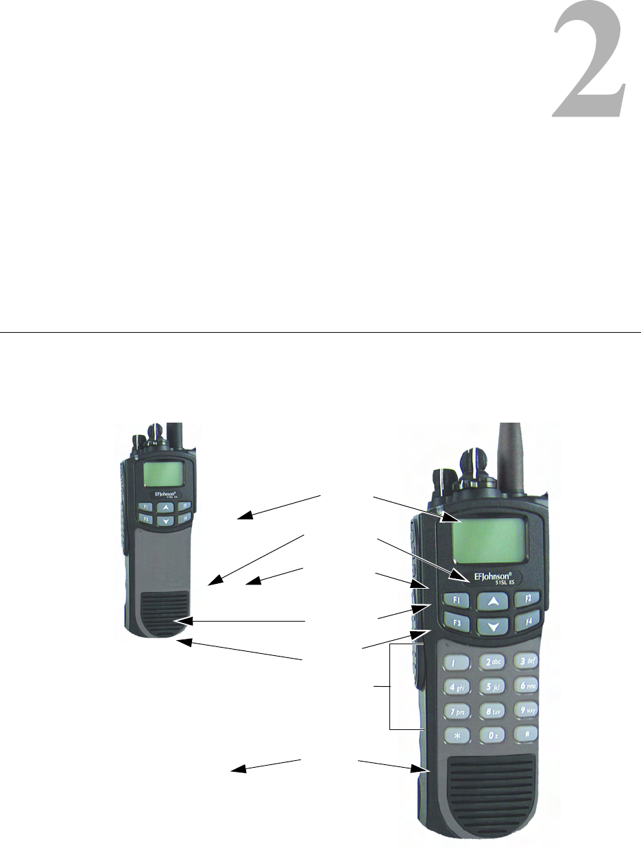
2.1 Front Panel Controls
The location of these controls is shown in Figure 2.1.
Figure 2.1 Front Panel Controls
Speaker
Display
DTMF Keypad
Option Keys
Microphone
Limited Keypad Model
Up/Down Sw
Menu/Option
Keys
<F1> = Exit
In Various Modes:
<F2> = Select/Menu
Enable
<F3> =
<F4> =
DTMF Keypad Model
2-2 5100 ES Models II/III Portable Radio Operating Manual March 2008
Controls and Display
Microphone - The microphone is located behind the small opening shown in Figure 2.1.
For best results, hold the radio 2-3 inches from you mouth and speak at a normal
conversational level. Do not shout since it distorts your voice and does not increase range.
Display - This is a graphical LCD (Liquid Crystal Display). The display backlight can be
programmed to turn on when any key is pressed or when the Backlight option switch is
pressed or menu parameter selected (see Section 3.5).
Up/Down Switch - Selects zones when multiple zones are programmed (see Section 3.3).
Pressing the upper part of the switch selects the next higher number and pressing the lower
part selects the next lower number. This control also provides up/down select in the menu
mode and in other modes when up/down select is required.
<F1> - In menu mode (see Section 4.3), functions as a step back and exit switch. If menu
mode is not used, it is a programmable option switch.
<F2> - Selects the menu mode when that mode is enabled by programming. Also
functions as an Enter or Select switch in the menu and other modes. If menu mode is not
used, it is a programmable option switch.
<F3>, <F4> - Programmable option switches.
DTMF Keypad - The full keypad DTMF models include the 12 keys required to dial
telephone and unit ID numbers.
Speaker - The radio speaker is located near the bottom of the front panel. When a speaker/
microphone is used, it is automatically detected when the Opt Sel 1 line of the accessory
connector is pulled low. The logic then automatically disables the internal speaker.
March 2008 5100 ES Models II/III Portable Radio Operating Manual 2-3
Controls and Display
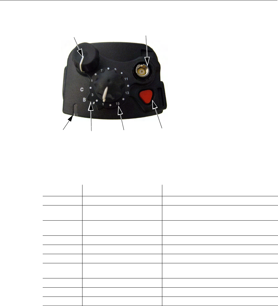
2.2 Top Panel Controls
Figure 2.2 Top Panel Controls
Multi-Function Indicator - Indicates the following conditions:
Note This indicator is disabled if the Surveillance mode is programmed (see Section 4.8).
Certain failures encountered during radio startup are indicated by blinking of the Orange
LED. The Type of failure is indicated by the number of times the LED blinks (1 to 10) as
described in Table 2.2.
Table 2.1 LED Indicators
LED Color LED Duration Description
Red ON Tx: clear
Red 125 ms ON 125 ms OFF Tx: CLEAR with low battery Tx: trunking system
busy
Red 125 ms ON 125 ms OFF 125 ms
ON 750 ms OFF Rx: Secure Group
Red 750 ms ON 125 ms OFF Rx: Secure individual call
Green ON Rx: clear conventional or trunking
Green 750 ms ON 125 ms OFF Rx: clear individual call
Orange Continuous until Self Test
complete Self Test state
Orange ON Tx: Secure
Orange 125 ms ON 125 ms OFF Tx: SECURE with low battery
Orange Blinking (1 to 10 times) Startup Failure. See Table 2.2 for details
Emergency
(Option)
Power ON-OFF/
Volume Adj
Channel
Switch
Antenna
Connector
Option
Switch Switch
Multi-Function
Indicator

2-4 5100 ES Models II/III Portable Radio Operating Manual March 2008
Controls and Display
Table 2.2 LED Startup Failure Indications
ON-OFF/Volume - Turning the knob clockwise turns power on and sets the volume level.
Turning it counterclockwise to the detent turns power off. The minimum volume level can
be set by programming. Soft power down can be programmed as described in Section
3.1.2, and the volume control can be disabled as described in Section 3.1.3.
Channel Switch - This 16-position switch selects up to 16 channels in the current zone.
Additional zones can be programmed to allow up to 864 channels to be selected by this
switch. This control can be disabled as described in Section 3.3.
Rotary Option Switch - This is a three-position switch that can be programmed to control
various options. The “A” position is “on” and the “B” and “C” positions are “off” (see
Section 4.1). When this switch is programmed to select zones, “A” selects Zone 1, “B”
Zone 2, and “C” Zone 3 if applicable.
Antenna Connector - This is the connection point for the antenna. Make sure the antenna
is tight before using the radio.
Emergency Switch - This switch or some other option switch can be programmed as an
Emergency switch to alert a dispatcher of an emergency condition. Refer to Sections 5.9
and 6.9 for more information. This switch can also be programmed for other functions.
Orange LED
Blinks Startup Failure Indicated Description
1 Incorrect Software Boot Loader is not the expected version
2 Bad File Format Parameter file version doe not match radio’s
software
3 Parms Fail Invalid backup copy of parameters stored in SPI
Flash device
4 Bad Band Radio band stored in parameter file does not match
the radio band in the tuning parameters
5 Corrupt Parms Parameters file contains an error, although
parameters checksum is valid
6 EEPROM Fail Self test timed out without successful read/
verification of parameter file
7 DSP Fail PowerPC never received Power-up message from
the DSP
8 Cycle Power Communication failure between DSP and back-end
ADC on the RF Deck
9 HC08 Init Fail HC08 was not initialized correctly and cannot be
accessed
10 Zone Fail Number of zones exceeds the number of zones for
which the radio was optioned
March 2008 5100 ES Models II/III Portable Radio Operating Manual 2-5
Controls and Display
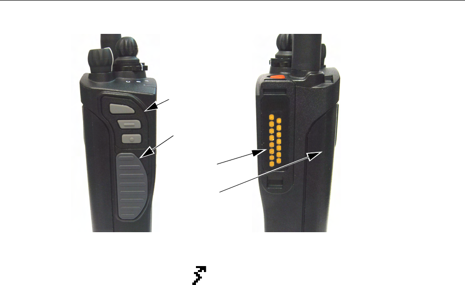
2.3 Side Controls
Figure 2.3 Side Controls and Jacks
PTT (Push-To-Talk) Switch - This switch is pressed to turn the transmitter on to transmit
a message. It is then released to listen. Transmitting is indicated when the top panel
indicator is constant red or is displayed (surveillance mode only, see Section 4.8).
Option Switches 1, 2, and 3 - Each of these switches can be programmed to control a
specific function (see Section 4.1). In addition, they can be programmed for soft power
down (see Section 3.1.2). These switches can also be temporarily disabled by the keypad
lock feature (see Section 3.6) or permanently disabled.
Battery - To remove the battery, press the release button on the bottom and pivot the
bottom of the battery outward.
Accessory Connector - This is the connection point for optional accessories such as a
speaker/microphone or earphone. It is also the connection point for the computer when
programming the radio or for data equipment when the P25 Packet Data feature is used
(see Section 5.14.10).
Option Switches
PTT Switch
Battery Pack
Accessory
Connector
1
2
3
2-6 5100 ES Models II/III Portable Radio Operating Manual March 2008
Controls and Display
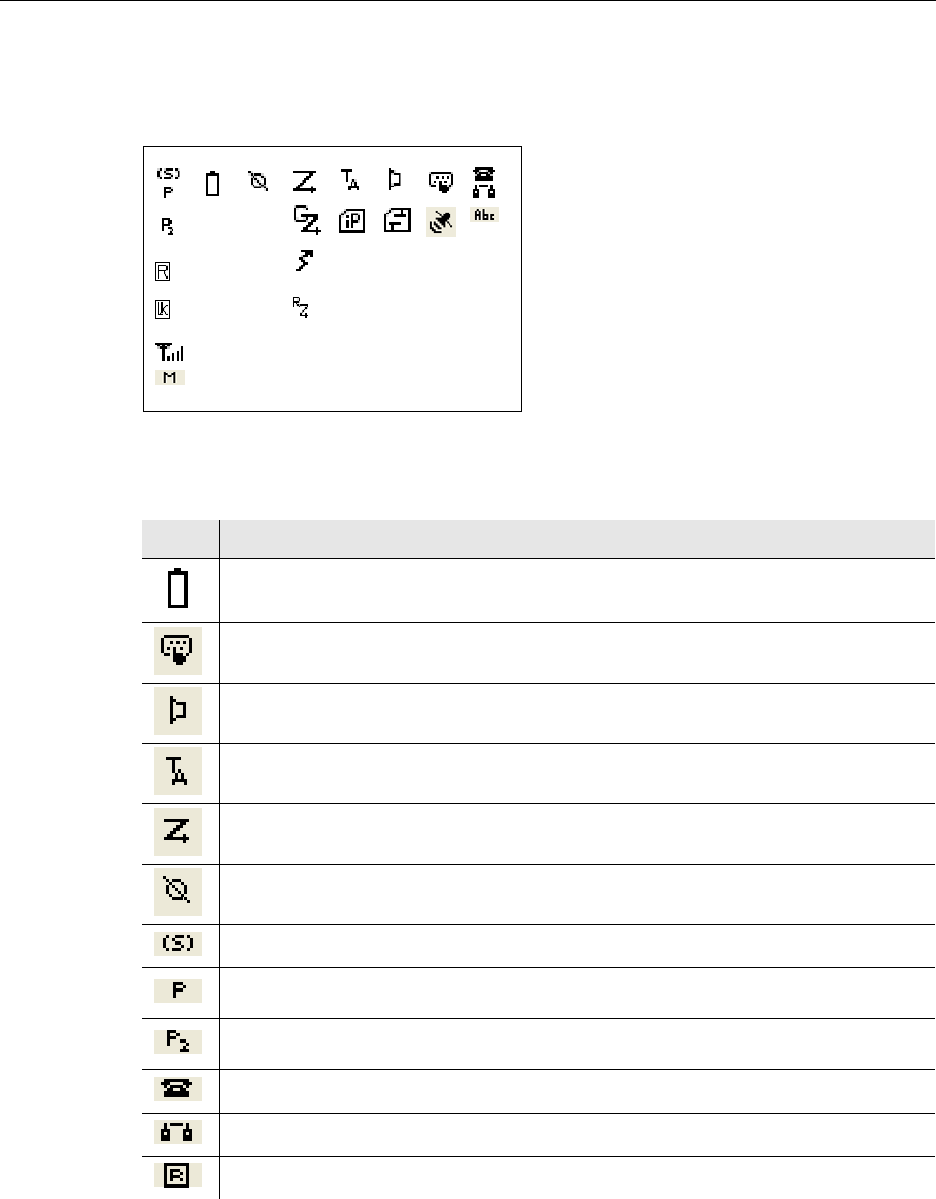
2.4 Display
The front panel display is shown below. Icons are typically shown in the upper part of the
display and text messages in the lower part.
Figure 2.4 Graphical Display
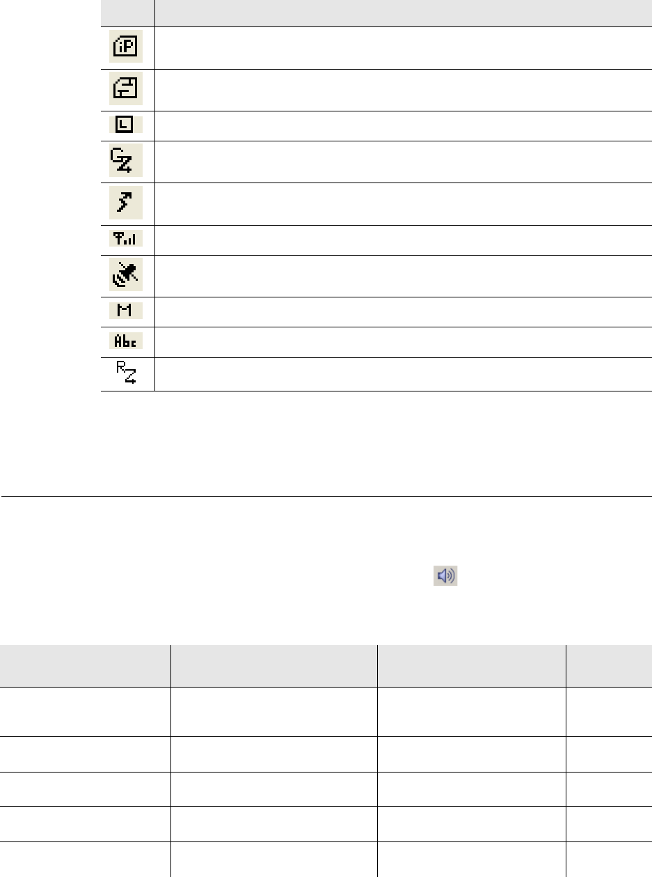
The icons are as follows:
Figure 2.5 5100 Icons
Icon Description
Low Battery
Keypad programming/edit mode – Displayed when the radio is in a mode where the user can edit
radio parameters
Monitor enabled
Repeater talk-around enabled
Scan enabled
Security enabled
The current channel is in the enabled scan list (only when scan is on or when in scan edit mode)
The current channel is the priority channel in the enabled scan list (only when scan is on or when
in scan edit mode)
The current channel is the priority 2 channel in the enabled scan list (only when scan is on or
when in scan edit mode)
Interconnect mode enabled
Private call mode enabled
Roaming (only used with Multinet trunking)
March 2008 5100 ES Models II/III Portable Radio Operating Manual 2-7
Controls and Display
2.5 Signaling Tones
Information is communicated to users of the 5100 ES radio using signal tones and alerts
and by LED signaling. Table 2.3 shows the information and signaling tones supported by
the 5100 ES radio. If you are viewing a PDF of this manual on a computer equipped
with a sound card, double-click on the Horn icon ( ) next to the Message Name to
hear the tone.
P25 Data Context enabled – Radio is ready for data operations
P25 Data Channel Grant – Radio is operating on a data channel
Site Lock (only used with Multinet trunking)
Multinet trunking group scan enabled
Transmit – Displayed while radio is transmitting while surveillance mode is enabled
Signal strength – indicates an acceptable site (only used with Multinet trunking)
GPS link active
Call history – used in conventional call alert, unit call, or text messaging when selecting a unit ID
Text message mode active
Radio Wide Scan Enabled
Figure 2.5 5100 Icons
Icon Description
Table 2.3 Tones for the 5100 ES Radios
Message Name Message Description Audible Description Tone
Category
Action Performed An action has been performed such as
selecting an item in List One high pitched beep, one
medium pitched beep and one
high pitched beep
Keypress
Alert TX Warning Timer for Group, Unit, and
Interconnect Calls High Pitched Beep Action
Alert Site Trunking Radio is in Site Trunking High pitched beep Action
Alert Tone Adjust Used when adjusting the Volume for
Alert Tones Medium pitched tone Keypress
Analog Signaling Side
Tone Occurs during Conventional Analog
Pre ANI Signaling Medium pitched continuous tone Action

2-8 5100 ES Models II/III Portable Radio Operating Manual March 2008
Controls and Display
Automatic Call Back A Voice Channel is available from a
previous request One high pitched beep, one
medium pitched beep and one
high pitched beep
Action
Bad Invalid Key Presses, Inadequate
Permissions / Self Test Fail Short Low Pitched Tone Action
Call Alert ACK Call Alert Acknowledgement has been
Received Six medium pitched beeps Action
Call Alert Received Call Alert Page has been Received Six medium pitched beeps
repeated every 6 seconds Action
Channel Busy System is currently busy Group of 4 Low Pitched Tones Action
Clear Alert Tone Radio receives a Secure call while in a
Clear Mode - PCC Option Medium Pitched Beep Action
DTMF Keypress DTMF Keypress Medium pitched continuous tone Action
Dynamic Regrouping • Dynamically Regrouping Command
has been received
• Talk Permit Tone while Dynamic
Regrouped
Gurgle Action
Emergency Alarm ACK Emergency Alarm Acknowledged
Successful A group of 5 medium pitched tones Action
Emergency Button
Press Emergency button has been Pressed Medium pitched long tone Action
Emergency Canceled Emergency is Canceled Medium pitched very long tone Action
Enhanced Unit Call Enhanced Unit Call is Received Three medium pitched tones
repeated 4 times every 6 seconds Action
Error Timeout States, Change Keyset Fail,
TX Timeout, Attempt to TX Clear when
Strapped Secure and vice versa
Low Pitched Continuous Tone Action
Failsoft Trunking System has Failed Two medium pitched beeps
repeated continuously Action
Feature OFF Binary Feature has been Turned OFF Medium pitched beep followed be
a lower pitched beep Keypress
Key Fail After channel change, Radio does not
have the assigned key Six medium pitched long tones Action
Key Fail PTT After PTT, Radio is in Secure mode
but does not have the assigned key Continuous medium pitched long
tones Action
Keyloader/Menu Enter
Mode Enter Menu Mode, Keyloader
Attached Medium Pitched Beep followed by
a higher pitched beep Keypress
Keyloader/Menu Exit
Mode Exit Menu Mode, Keyloader Detached High pitched beep followed by a
medium pitched beep Keypress
Low Battery The battery strength is getting low.
Charge or replace the battery
immediately
Two medium pitched beeps Action
Message / Status ACK Message / Status Acknowledgement
has been Received Six medium pitched beeps Action
Table 2.3 Tones for the 5100 ES Radios (Continued)
Message Name Message Description Audible Description Tone
Category

March 2008 5100 ES Models II/III Portable Radio Operating Manual 2-9
Controls and Display
Non-Enhanced Unit Call Non Enhanced Unit Call is Received Two medium pitched beeps
repeated every 6 seconds Action
OTAR
Acknowledgement OTAR Hello Acknowledgement
Received High Pitched Beep Action
Out of Range Trunking Radio is in an Out of Range
State Low pitched, very long tone
repeated Action
Priority Call Received Radio has received a Priority Call Two low pitched beeps Action
Radio Self-Test Pass Self Test has Passed Medium Pitched Beep followed by
a higher pitched beep Keypress
Return to Normal • Dynamic Regrouping has been
Canceled
• Voltage has returned to Normal
• Temperature has returned to Normal
• Conventional: TX Penalty Timer has
Expired
Medium Pitched Beep followed by
a higher pitched beep Action
Ring Radio has received an interconnect
and is waiting for Unit Call target
subscriber to respond
Telephone Ringing Action
System Retry Tone that occurs after the 2nd ISP or
ISW retry Continuous low pitched tone Action
Talk Permit Tone (When PTT Button is Pressed)
verifying that the system is accepting
transmissions
Three medium pitched beeps Action
Temperature Change Temperature has changed from
Normal to Hot or Too Hot Two medium pitched beeps Action
Unprogrammed
Channel Radio is turned to an Unprogrammed
Channel Low Pitched Continuous Tone Action
Valid Keypress / Feature
ON Valid Key Press or a Feature has been
turned on Medium Pitched Short Tone Keypress
Volume Boundary Volume boundary reached when
adjusting the volume with Volume Up /
Down Buttons
Two medium pitched beeps Action
Table 2.3 Tones for the 5100 ES Radios (Continued)
Message Name Message Description Audible Description Tone
Category
2-10 5100 ES Models II/III Portable Radio Operating Manual March 2008
Controls and Display