E F Johnson 2425180 PTT 800 MHz SMR User Manual 51xx Prelim Operating Manual
E. F. Johnson Company PTT 800 MHz SMR 51xx Prelim Operating Manual
Contents
022702 Operator Manual
1
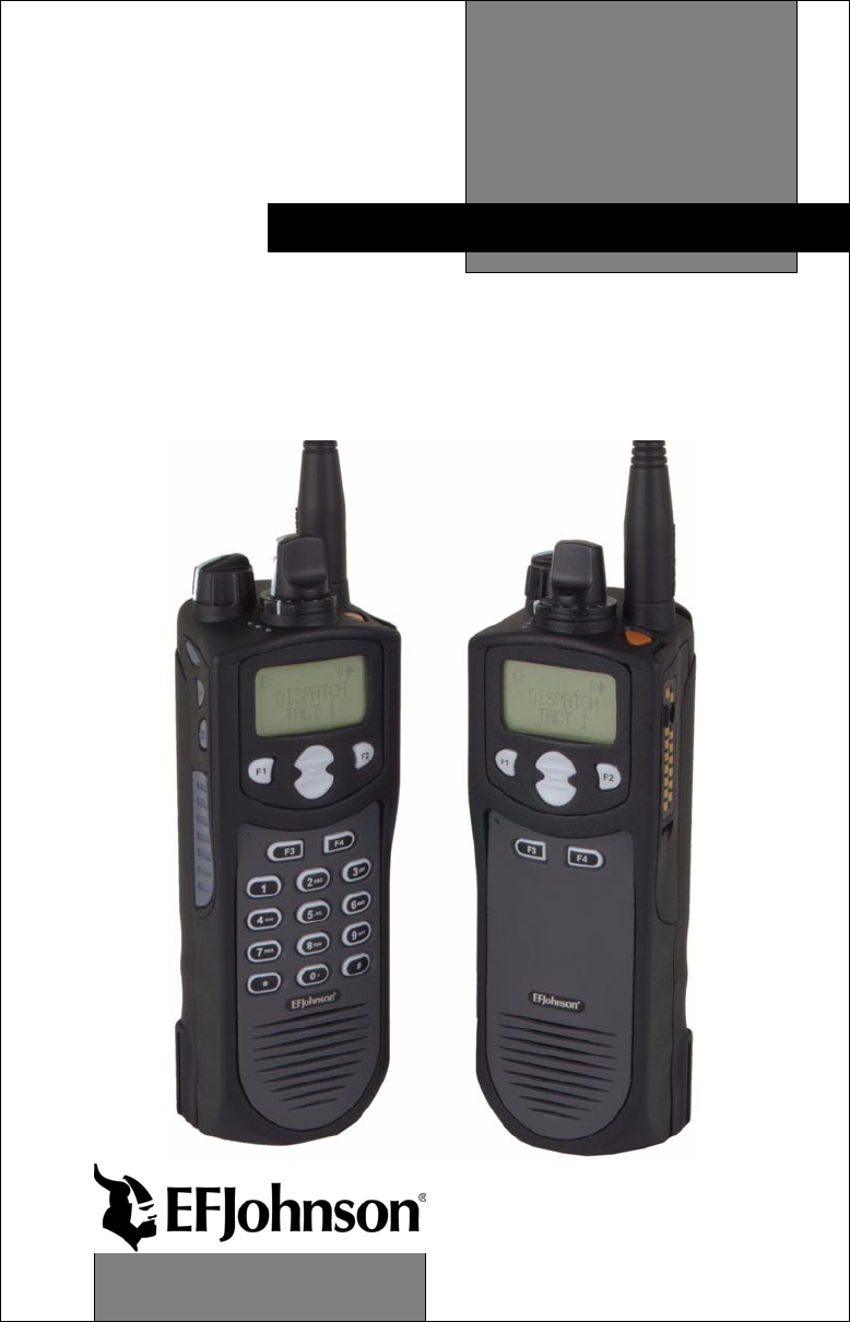
51xx Series
FM Portable Radio
Project 25, Conventional
SMARTNET
™
, SmartZone
®
PRELIMINARY
OPERATING
MANUAL

LAND MOBILE PRODUCT WARRANTY - The manufacturer’s
warranty statement for this product is available from your product
supplier or from the E.F. Johnson Company, 299 Johnson Avenue, Box
1249, Waseca, MN 56093-0514. Phone (507) 835-6222.
Copyright© 2001 by the E.F. Johnson Company
E.F. Johnson Company, which was founded in 1923, designs, manufac-
tures, and markets radio communication products, systems, and services
worldwide. E.F. Johnson produces equipment for land mobile radio and
mobiletelephone services which include business, industrial, government,
public safety, and personal users.
Viking Head/EFJohnson logo and Call Guard® are trademarks of the E.F.
Johnson Company. SMARTNET™, SmartZone®, Call Alert™, Enhanced
Private Conversation™, and Private Conversation II™ are trademarks of
Motorola, Inc. All other company and/or product names used in this manual are
trademarks and/or registered trademarks of their respective manufacturer. The
IMBE™ voice coding technology embodied in this product is protected by
intellectual property rights including patent rights of Digital Voice Systems, Inc.

SAFETY TRAINING INFORMATION
4
SAFETY TRAINING INFORMATION
WARNING
This radio produces RF electromagnetic energy when transmitting and is
designed and classified for “Occupational Use Only”. Radio equipment
with this classification must be used only during the course of employ-
ment by individuals aware of the hazards and the ways to minimize such
hazards. This radio is NOT intended for use by the General Population in
an uncontrolled environment.
This radio has been tested and complies with FCC RF exposure limits for
“Occupational Use Only”. In addition, it complies with the following
standards and guidelines with regard to RF energy and electromagnetic
energy levels and evaluation of such levels for exposure to humans:
•FCC OET Bulletin 65 Edition 97-01 Supplement C, Evaluating
Compliance with FCC Guidelines for Human Exposure to Radio
Frequency Electromagnetic Fields.
•American National Standards Institute (C95.1-1992), IEEE Standard
for Safety Levels with Respect to Human Exposure to Radio
Frequency Electromagnetic Fields, 3 kHz to 300 GHz.
•American National Standards Institute (C95.3 -1992), IEEE Recom-
mended Practice for the Measurement of Potentially Hazardous
Electromagnetic Fields - RF and Microwave.
CAUTION
To ensure that your exposure to RF electromagnetic energy is within the FCC
allowable limits for occupational use, always adhere to the following guidelines:
•DO NOT operate the radio without the proper antenna attached. This may
damage the radio and cause FCC RF exposure limits to be exceeded. The
proper antenna is the antenna supplied with the radio by the manufacturer
or an antenna specifically authorized by the manufacturer for use with this
radio.

SAFETY TRAINING INFORMATION
5
•DO NOT transmit more than 50% of total radio use time (50% duty cycle).
Transmitting for more than 50% of the time can cause FCC RF exposure
compliance requirements to be exceeded. This radio is transmitting when-
ever Tx is indicated in the display. Pressing the PTT switch on the side
usually causes the radio to transmit.
•DO NOT use any accessories not specifically authorized by the E.F.
Johnson Company for use with this radio such as batteries, speaker-
microphones, belt clips, and antennas. The use of unauthorized accessories
can cause FCC RF exposure compliance requirements to be exceeded.
•ALWAYS keep the antenna and radio at least 2.54 cm (1.0 inch) away from
your body when transmitting to ensure FCC RF exposure compliance
requirements are not exceeded. The best transmission quality results when
the antenna is at least 5 cm (2 inches) away from your mouth and angled
slightly to one side.
NOTE: The preceding information is provided to make you aware of RF
exposure and what to do to ensure that this radio is operated within FCC RF
exposure limits.
Electromagnetic Interference/Usage Compatibility
This device complies with Part 15 of the FCC rules. Operation is subject to the
condition that this device does not cause harmful interference. In addition,
changes or modification to this equipment no expressly approved by the E.F.
Johnson Company could void the user’s authority to operate this equipment
(FCC Rules, 47CFR Part 15.19).
DO NOT operate it in areas that are sensitive to RF energy such as aircraft,
hospitals, blasting sites, and fuel storage sites. Areas with potentially flammable
atmospheres are usually, but not always, clearly posted. These may include gas
stations, fuel and chemical storage and transfer stations, below deck on boats,
and areas where the air contains flammable chemicals or particles such as grain
dust or metal powders.
Dispose of the nickel metal-hydride battery used by this radio in accordance with
local regulations. DO NOT dispose of it in fire because it can explode. Also, do
not short the terminals because it may become very hot.

FEATURES
6
FEATURES
General Features
•Programmable for the following modes of operation:
– Conventional analog
– Conventional Project 25 (digital)
– SMARTNET™/SmartZone® trunked (analog or digital)
•Up to 16 zones with up to 16 channels each programmable
(256 channels total)
•Large liquid crystal display (LCD) with backlight
•Nine programmable option switches (full keypad model)
•Standard and radio-wide scan modes
•Time-out timer
•Power-up password access available to prevent unauthorized usage
Conventional Features
•Up to 256 channels or talk groups programmable
•Repeater talk-around
•Monitor mode selected by option switch
•Carrier or Call Guard® controlled squelch on analog channels
•Penalty and conversation timers
•Priority channel sampling when scanning
•Busy channel lockout (transmit disable on busy)
•SecureNet™ or 460 secure communication available on analog
channels, DES-OFB on Project 25 channels
•Individual ID calls on Project 25 channels
•User selectable high and low power output
•Emergency switch (P25 channels only)
•Keypad programming

FEATURES
7
SMARTNET™ II/SmartZone® Features
•Up to 256 talk groups programmable
•Group, Enhanced Private Conversation™, Private Conversation II™,
and Telephone Calls
•Emergency alarms to alert dispatcher of emergency conditions
•Emergency calls for high priority system access
•Failsoft operation on a predefined conventional channel if trunked sys-
tem fails
•Priority group calls detected while listening to other group calls
•Call Alert™ (send and receive pages)
•Predefined messages (up to 16) can be sent to a dispatcher
•Predefined status conditions (up to 8) can be sent to a dispatcher
•Dynamic regrouping (dispatcher can automatically gather users on a
channel to receive a message)
•Roaming (SmartZone only)
•SecureNet™ or 460 secure communication available
NOTE: The availability of many of the preceding features is controlled by
system operator programming of your transceiver, installed options, and
the capabilities of the radio system being accessed.

FEATURES
8
NOTES

TABLE OF CONTENTS
9
TABLE OF CONTENTS
SAFETY TRAINING INFORMATION . . . . . . . . . . . . . . . . . . . . . . . . 4
FEATURES . . . . . . . . . . . . . . . . . . . . . . . . . . . . . . . . . . . . . . . . . . . . . . 6
General Features. . . . . . . . . . . . . . . . . . . . . . . . . . . . . . . . . . . . . . . . . 6
Conventional Features . . . . . . . . . . . . . . . . . . . . . . . . . . . . . . . . . . . . 6
SMARTNET™ II/SmartZone® Features. . . . . . . . . . . . . . . . . . . . . . 7
OPTION SWITCH FUNCTIONS. . . . . . . . . . . . . . . . . . . . . . . . . . . . 11
CONTROLS AND DISPLAY. . . . . . . . . . . . . . . . . . . . . . . . . . . . . . . 13
Front Panel Controls. . . . . . . . . . . . . . . . . . . . . . . . . . . . . . . . . . . . . 13
Top Panel Controls. . . . . . . . . . . . . . . . . . . . . . . . . . . . . . . . . . . . . . 15
Side Controls . . . . . . . . . . . . . . . . . . . . . . . . . . . . . . . . . . . . . . . . . . 16
Display . . . . . . . . . . . . . . . . . . . . . . . . . . . . . . . . . . . . . . . . . . . . . . . 17
GENERAL OPERATION. . . . . . . . . . . . . . . . . . . . . . . . . . . . . . . . . . 18
Introduction . . . . . . . . . . . . . . . . . . . . . . . . . . . . . . . . . . . . . . . . . . . 18
Turning Power On and Setting Volume . . . . . . . . . . . . . . . . . . . . . . 18
Power-Up Password . . . . . . . . . . . . . . . . . . . . . . . . . . . . . . . . . . . . . 19
Backlight. . . . . . . . . . . . . . . . . . . . . . . . . . . . . . . . . . . . . . . . . . . . . . 20
Option Switches . . . . . . . . . . . . . . . . . . . . . . . . . . . . . . . . . . . . . . . . 20
Keypad Lock . . . . . . . . . . . . . . . . . . . . . . . . . . . . . . . . . . . . . . . . . . 21
Low Battery Indication. . . . . . . . . . . . . . . . . . . . . . . . . . . . . . . . . . . 21
Channel and Zone Selection. . . . . . . . . . . . . . . . . . . . . . . . . . . . . . . 21
Home Zone . . . . . . . . . . . . . . . . . . . . . . . . . . . . . . . . . . . . . . . . . . . . 22
Time-Out Timer . . . . . . . . . . . . . . . . . . . . . . . . . . . . . . . . . . . . . . . . 22
Tone Enable/Disable . . . . . . . . . . . . . . . . . . . . . . . . . . . . . . . . . . . . 23
Scanning . . . . . . . . . . . . . . . . . . . . . . . . . . . . . . . . . . . . . . . . . . . . . . 23
Secure Communication . . . . . . . . . . . . . . . . . . . . . . . . . . . . . . . . . . 28
Transceiver Operating Modes . . . . . . . . . . . . . . . . . . . . . . . . . . . . . 28
CONVENTIONAL FEATURES. . . . . . . . . . . . . . . . . . . . . . . . . . . . . 29
Introduction . . . . . . . . . . . . . . . . . . . . . . . . . . . . . . . . . . . . . . . . . . . 29
Display Mode Selection . . . . . . . . . . . . . . . . . . . . . . . . . . . . . . . . . . 30
Monitoring Before Transmitting . . . . . . . . . . . . . . . . . . . . . . . . . . . 30
Monitor Mode. . . . . . . . . . . . . . . . . . . . . . . . . . . . . . . . . . . . . . . . . . 31
Busy Channel Lockout . . . . . . . . . . . . . . . . . . . . . . . . . . . . . . . . . . . 32
Call Guard Squelch. . . . . . . . . . . . . . . . . . . . . . . . . . . . . . . . . . . . . . 32
Penalty Timer . . . . . . . . . . . . . . . . . . . . . . . . . . . . . . . . . . . . . . . . . . 33
Conversation Timer . . . . . . . . . . . . . . . . . . . . . . . . . . . . . . . . . . . . . 34
Repeater Talk-Around . . . . . . . . . . . . . . . . . . . . . . . . . . . . . . . . . . . 34

TABLE OF CONTENTS
10
Power Output Select. . . . . . . . . . . . . . . . . . . . . . . . . . . . . . . . . . . . . 34
Emergency Mode (Conventional) . . . . . . . . . . . . . . . . . . . . . . . . . . 35
Conventional Mode Scanning . . . . . . . . . . . . . . . . . . . . . . . . . . . . . 35
Priority Channel Sampling . . . . . . . . . . . . . . . . . . . . . . . . . . . . . . . . 36
Placing and Receiving Standard Conventional Calls . . . . . . . . . . . . 37
DTMF/ANI Signaling . . . . . . . . . . . . . . . . . . . . . . . . . . . . . . . . . . . 38
Project 25 Mode Features. . . . . . . . . . . . . . . . . . . . . . . . . . . . . . . . . 39
Keypad Programming. . . . . . . . . . . . . . . . . . . . . . . . . . . . . . . . . . . . 40
Channel Parameter Programming. . . . . . . . . . . . . . . . . . . . . . . . . . . 43
SMARTNET/SMARTZONE FEATURES . . . . . . . . . . . . . . . . . . . . 46
Introduction . . . . . . . . . . . . . . . . . . . . . . . . . . . . . . . . . . . . . . . . . . . 46
Viewing Unit ID. . . . . . . . . . . . . . . . . . . . . . . . . . . . . . . . . . . . . . . . 46
Standard Group Calls . . . . . . . . . . . . . . . . . . . . . . . . . . . . . . . . . . . . 46
Enhanced Private Conversation Calls . . . . . . . . . . . . . . . . . . . . . . . 47
Private Conversation II Calls . . . . . . . . . . . . . . . . . . . . . . . . . . . . . . 51
Telephone Calls . . . . . . . . . . . . . . . . . . . . . . . . . . . . . . . . . . . . . . . . 53
Call Alert . . . . . . . . . . . . . . . . . . . . . . . . . . . . . . . . . . . . . . . . . . . . . 56
Messaging. . . . . . . . . . . . . . . . . . . . . . . . . . . . . . . . . . . . . . . . . . . . . 57
Sending Status Conditions . . . . . . . . . . . . . . . . . . . . . . . . . . . . . . . . 58
Emergency Alarm and Emergency Call. . . . . . . . . . . . . . . . . . . . . . 58
Failsoft Operation. . . . . . . . . . . . . . . . . . . . . . . . . . . . . . . . . . . . . . . 59
SMARTNET/SmartZone Scanning . . . . . . . . . . . . . . . . . . . . . . . . . 60
Dynamic Regrouping . . . . . . . . . . . . . . . . . . . . . . . . . . . . . . . . . . . . 60
SmartZone Features . . . . . . . . . . . . . . . . . . . . . . . . . . . . . . . . . . . . . 61
MISCELLANEOUS. . . . . . . . . . . . . . . . . . . . . . . . . . . . . . . . . . . . . . . 62
Supervisory Tones . . . . . . . . . . . . . . . . . . . . . . . . . . . . . . . . . . . . . . 62
Rechargeable Battery Pack. . . . . . . . . . . . . . . . . . . . . . . . . . . . . . . . 64
System Operator Programming . . . . . . . . . . . . . . . . . . . . . . . . . . . . 66
Speaking Into Microphone . . . . . . . . . . . . . . . . . . . . . . . . . . . . . . . . 66
Operation At Extended Range . . . . . . . . . . . . . . . . . . . . . . . . . . . . . 66
Licensing . . . . . . . . . . . . . . . . . . . . . . . . . . . . . . . . . . . . . . . . . . . . . 66
Transceiver Service . . . . . . . . . . . . . . . . . . . . . . . . . . . . . . . . . . . . . 67
INDEX . . . . . . . . . . . . . . . . . . . . . . . . . . . . . . . . . . . . . . . . . . . . . . . . . . 70

OPTION SWITCH FUNCTIONS
11
OPTION SWITCH FUNCTIONS
The programmable option switches are as follows:
•F1, F2, F3, and F4 keys on the front panel
•Three push-button switches on the side
•Orange push-button switch on the top panel
•Three-position A/B/C switch on top panel
These switches can control one function when a conventional
channel is selected and another when a SMARTNET/SmartZone channel
is selected. The available functions for each operating mode and the page
on which each function is described are listed in the following tables.
Consult your system operator to determine what functions are controlled
by each switch and then write the switch label next to the applicable func-
tion. Refer to page 20 for more option switch information.
CONVENTIONAL MODE
Switch Function See Page
Backlight 20
Clear/Secure 28
Displayed Information 30
High/Low Power 34
Home Zone 22
Individual ID Call 40
Keypad Lock 21
Keypad Programming 40
Monitor 31
Normal/Selective 32
Priority 36
Radio Wide Scan 24
Repeater Talk-Around 34
Scan 24
Scan Edit 26
Talk Group Select 39
Tones On-Off 23
Zone Select 21

OPTION SWITCH FUNCTIONS
12
SMARTNET/SMARTZONE MODE
Switch Function See Page
Backlight 20
Call Alert 56
Call Response 50, 52
Clear/Secure 28
Home Zone 22
Keypad Lock 21
Message 57
Phone 53
Private Call 47, 51
Radio Wide Scan 24
Scan 24
Scan Edit 26
Site Lock (SmartZone only) 61
Site Search (SmartZone only) 61
Status 58
Tones On-Off 23
Zone Select 21
CONTROLS AND DISPLAY
13
CONTROLS AND DISPLAY
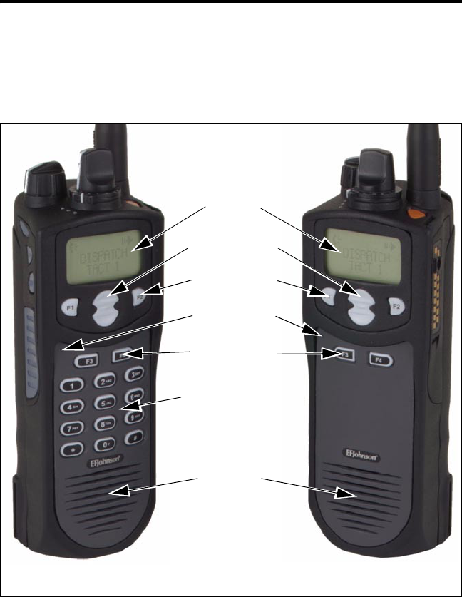
Front Panel Controls
Speaker - The transceiver speaker is located behind this grill. When a
speaker/microphone is used, this speaker is automatically disabled.
Microphone - The microphone is located in this area. For best results,
hold the transceiver 2-3 inches from you mouth and speak at a normal
conversational level.
Speaker
Display
DTMF Keypad
Option Keys
Microphone
Full Keypad Model Limited Keypad Model
Up/Down Sw
Option Keys

CONTROLS AND DISPLAY
14
Front Display - This is a dot-matrix graphical LCD (Liquid Crystal Dis-
play). The display backlight can be programmed to turn on when any key
is pressed or when the Backlight option switch is pressed (see page 20).
DTMF Keypad - The full keypad, 17-key models include the keys
required to dial telephone, unit ID, and group ID numbers and also to
enter numbers during for keypad programming.
F1 - F4 - These keys are available with both full and limited keypad
models, and they can be system operator programmed to control a
specific function. The key functions can be different for each operating
mode (see page 11). Other programmable option switches are located on
the top and side panels (see preceding information).
CONTROLS AND DISPLAY
15
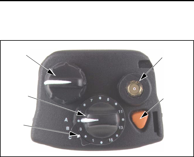
Top Panel Controls
On-Off/Volume - Turning the knob clockwise turns power on and sets
the volume level. Turning it counterclockwise to the detent turns power
off.
Channel Switch - This 16-position switch allows up to 16 channels to be
selected. This switch operates in conjunction with up to 16 programmable
zones to allow up to 256 channels to be selected.
Programmable Option Switch - This is a three-position selector switch
that can be system operator programmed to control some function (see
page 11).
Antenna Connector - Connection point for the antenna. Make sure that
the antenna is tight before using the radio.
Emergency Switch - If the radio is programmed for emergency transmis-
sions, pressing this switch alerts a dispatcher, for example, of an emer-
gency condition. Refer to descriptions on pages 35 and 58 for more
information.
Emergenc
y
(Option)
On-Off
Volume
Channel
Switch
Antenna
Connecto
r
Option
Sw
Switch
CONTROLS AND DISPLAY
16
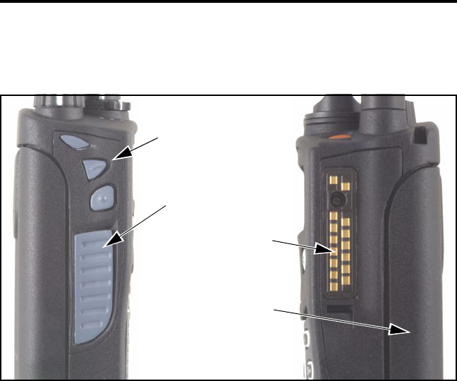
Side Controls
Option Switches - These three switches can be system operator pro-
grammed to control a specific function (see page 11).
PTT Switch - This switch is pressed to turn the transmitter on. The indi-
cator on the top panel lights red when the transmitter is keyed.
Accessory Connector - Connection point for optional accessories such
as a speaker/microphone.
Battery Pack - To remove the battery, press the release on the bottom
toward the front of the transceiver and slide the battery outward.
Option Switches
PTT Switch
Battery Pack
Accessory
Connector
CONTROLS AND DISPLAY
17
Display
The front panel display is shown above, and the following informa-
tion is indicated:
Alphanumeric Characters - This area of the display indicates the
selected channel, error conditions, and other information.
Sec - Indicates that transmissions are encrypted (see page 28).
Dig - Indicates that a digital (Project 25) conventional channel is selected.
Rx - Indicates that a carrier is being detected on the selected or scanned
channel.
Tx - Indicates the transmitter is keyed.
Pgm - Indicates that the keypad programming mode is selected (see
page 40).
SL - Indicates that the displayed channel is in the scan list (see page 25).
Pri - Indicates that the displayed channel is programmed as the current
group’s priority channel (see page 36).
Sec Dig Rx Tx Pgm SL Pri Call ID Scan
Alphanumeric Display

GENERAL OPERATION
18
Call ID - Indicates that the display is showing the ID of the calling party
(see page 47).
Scan - Indicates that system scan is activated (see page 23).
GENERAL OPERATION
Introduction
The following section describes features available with both trunked
and conventional operation. Features unique to conventional channels are
described starting on page 29, and features unique to SMARTNET/
SmartZone channels are described starting on page 46.
Turning Power On and Setting Volume
Power is turned on and off by the On-Off/Volume switch on the top
panel. When power is initially turned on, an alert tone sounds and the
indicator on the top panel flashes green. If a SMARTNET/SmartZone
channel is selected, the zone alias is then displayed followed by the unit
ID (see page 46). The selected channel is then indicated.
To turn power off, turn the On-Off/Volume knob counterclockwise
until a click occurs. The display may remain on for a few seconds after
power is turned off. It is recommended that power not be turned back on
again until the display is blank.
The relative volume level can be determined by noting the position
of the index on the On-Off/Volume knob. To enable a reference tone for
setting the volume, proceed as follows:

GENERAL OPERATION
19
•If key press tones are enabled (see page 23), a short tone sounds when
front panel keys are pressed.
•If a conventional channel is selected and the Monitor option switch is
programmed (see page 31), pressing that switch unsquelches/squelches
the receiver and either voice or background noise is heard. If a
SMARTNET/SmartZone channel is selected, the receiver cannot be
manually unsquelched.
Power-Up Password
General
The power-up password feature prevents unauthorized use of the
transceiver. When it is enabled by system operator programming, an
eight-digit password must be entered to make the transceiver operational
each time power is turned on. Passwords can be entered even if the key-
pad is locked (see “Keypad Lock” on page 21). The default password is
eight zeros (00000000).
If this feature is enabled, proceed as follows to unlock the radio:
1. Turn radio power on and when “LOCKED” is displayed, enter the
eight-digit numeric password using the keypad. As each digit is
entered, a dash is displayed. If an incorrect digit is entered, press the F3
key and re-enter the entire password.
2. When all eight digits have been entered, press the F4 key. If the pass-
word is correct, the display indicates normal zone and then channel
information. If an incorrect password is entered, “LOCKED” is again
displayed.
Changing Password
The current password can be changed as follows:
1. The locked mode must be selected to change the password, so cycle
power if necessary to display “LOCKED”.

GENERAL OPERATION
20
2. Enter the old eight-digit password and press the # key (not F4). If the
correct password is entered, “NEW PSWD” is displayed.
3. Enter the new password and press F4. The password is changed.
Backlight
The backlight for the display and keypad can be manually turned on
by pressing the Backlight option switch if it is available. The backlight
can also be system operator programmed to automatically turn on when
any key is pressed. It then automatically turns off after a programmed
delay so that battery drain is minimized.
Option Switches
The programmable option switches are as follows:
•F1, F2, F3, and F4 on front panel (see illustration on page 13).
•The three push-button switches on the side panel (see illustration on
page 16).
•The 3-position selector switch and orange push-button switch on the
top panel (see illustration on page 15).
If your radio is programmed with both conventional and
SMARTNET/SmartZone channels (see page 29), these option switches
can be system operator programmed to control a different set of functions
for each channel type. For example, the F1 switch could select Hi/Lo
Power when a conventional channel is selected and Private Calls when a
SMARTNET/SmartZone channel is selected. The available functions in
each mode are indicated in the tables on pages 11 and 12. If the
programmed functions are not indicated in these tables, consult your
system operator to determine how your switches have been programmed.
If no option switch has been programmed to control a particular function,
that function may not be available or may be in a fixed mode.

GENERAL OPERATION
21
Keypad Lock
If the Keypad Lock option switch has been programmed, the keypad
can be locked (disabled) to prevent keys from being accidentally pressed.
To lock the keypad, simply press this switch. Then to unlock it again,
press and hold it until a tone sounds. The keypad can also be disabled by
system operator programming. It is then permanently disabled and cannot
be re-enabled by the user.
Low Battery Indication
When the battery voltage falls below a preset level, the radio can be
programmed so that any or all of the following indications occur:
•“Low Battery” flashes in the display every 5 seconds
•A chirp sounds every 5 seconds in the receive mode.
•A chirp sounds every 5 seconds in the transmit mode.
The battery should be recharged as soon as practical after a low
battery indication appears. Refer to page 64 for more battery information.
Channel and Zone Selection
Channel Select
To change the current channel, rotate the 16-position channel
selector knob on the top panel to the desired position. With SMARTNET/
SmartZone channels, the selected channel is always indicated by alias
(name). The alias is also displayed with conventional channels if the
Display Mode option switch is not programmed. If this switch is
programmed, the channel number or frequency may also be displayed
(see “Display Mode Selection” on page 30).
Zone Select
A zone is a group of up to any 16 conventional and SMARTNET/
SmartZone channels defined by system operator programming. Up to 16

GENERAL OPERATION
22
zones can be programmed for a total of 16 x 16 channels per zone or 256
channels. One use of zones may be to select groups of channels
programmed for operation in different geographical areas or radio
systems. If selectable zones have been programmed in your radio, consult
your system operator for more information on how they are used. Zones
are selected as follows:
1. Press the Zone option switch and the alias (name) of the current zone is
flashed in the display.
2. Use the number keys to enter the desired zone number or scroll through
the available zones using the Up/Down select switch.
3. When the desired zone is displayed or entered, select it by pressing the
F4 key or waiting 4 seconds.
Home Zone
The radio can be programmed with a home zone. Then when power
is turned on, the radio can be programmed so that either the home or last
selected zone is automatically selected.
If the Home Zone option switch is programmed, it can be used to
quickly select or change the home zone. To select the home zone, simply
press this switch. To change the home zone to the currently selected zone,
press and hold this switch until a tone sounds (approximately 1 second).
Time-Out Timer
The time-out timer disables the transmitter if it is keyed for longer
than the programmed time. It can be programmed on each channel for
times of 15 - 225 seconds or it can be disabled (not used). If the trans-
mitter is keyed continuously for longer than the programmed time, the
transmitter is disabled and an invalid condition tone sounds. Five seconds
before time-out occurs, an alert tone sounds to indicate that time-out is
approaching. The timer and tone are reset by releasing the PTT switch.

GENERAL OPERATION
23
One use of this feature is to prevent a channel from being kept busy
for an extended period by an accidentally keyed transmitter. It can also
prevent possible transmitter damage caused by transmitting for an exces-
sively long period. Conventional channels can also be programmed with
the Penalty and Conversation timers that are described starting on
page 33.
Tone Enable/Disable
The supervisory tones (see page 62) can be enabled and disabled by
the Tones On-Off option switch if it is programmed. When tones are
enabled by this switch, “TONE ON” is momentarily displayed and a tone
sounds. Conversely, when tones are disabled, “TONE OFF” is displayed
and no tone sounds. If the Tones On-Off option switch is not
programmed, tones are fixed in the on or off mode by system operator
programming.
Scanning
Introduction
Scanning cycles through a list of channels called a “scan list”,
checking each for messages. When a message is detected that your trans-
ceiver is programmed to receive, scanning stops and the message is
received. Shortly after the message is complete, scanning resumes (unless
it has been disabled).
There are two basic scan modes: Standard and Radio Wide. The
Standard mode is unique to the type of channel selected (conventional or
SMARTNET/SmartZone), and the Radio Wide mode is the same regard-
less of the channel type selected. Only one of these scan modes can be
enabled at a time. Therefore, if standard scanning is enabled while radio
wide scanning is occurring, radio wide scanning is automatically disabled
and vice versa. More information on these modes follows.

GENERAL OPERATION
24
Standard Scanning
Standard scanning monitors only channels that are the same type as
that currently selected. Therefore, if a conventional channel is selected,
only conventional channels are scanned, and if a SMARTNET channel is
selected, only SMARTNET channels are scanned. Standard scanning is
turned on and off by the Scan option switch as follows. If this switch is
not programmed, standard scanning is not available.
•To turn standard scanning on, press the Scan option switch. Scanning is
enabled when the “Scan” icon is indicated in the upper right corner of
the front panel display and “SCAN ON” is briefly displayed.
•To turn scanning off, press the Scan option switch again. The “Scan”
icon is then no longer indicated and “SCAN OFF” is briefly displayed.
•If the zone or channel is changed while scanning is selected, scanning
continues on the same or a different scan list (see scan list information
which follows).
Radio Wide Scanning
Radio wide scanning monitors the channels in the preprogrammed
radio wide scan list (see page 25). This list may contain up to 16 channels
of any type (conventional or SMARTNET/SmartZone) assigned to any
zone. Radio wide scanning is turned on and off by the Radio Wide Scan
option switch as follows. If this switch is not programmed, radio wide
scanning is not available.
•To turn radio wide scanning on, press the Radio Wide Scan option
switch. Scanning is enabled when “Scan” is indicated in the upper
right corner of the front panel display and “SCAN ON” is briefly
displayed.
•To turn radio wide scanning off, press the Radio Wide Scan option
switch again. The “Scan” icon is then no longer indicated and “SCAN
OFF” is briefly displayed.

GENERAL OPERATION
25
•If the zone or channel is changed while radio wide scanning, scanning
continues normally.
Scan Resume Delay
When a message is received or transmitted while scanning, there is a
system operator programmable delay before scanning resumes. The delay
after receiving a call prevents another message from being received
before you can make a response, and the delay after transmitting a call
ensures that you hear a response to your call instead of another message
occurring on some other channel.
Standard Mode Scan List
NOTE: The selected channel is always scanned.
With conventional operation, up to three scan lists can be
programmed. The list that is scanned is selected by the Scan option
switch as described on page 35. Selecting another conventional channel
does not change the current scan list. The scan lists are user program-
mable if the Scan Edit option switch is programmed (see page 26).
With SMARTNET/SmartZone operation, each channel can be
programmed so that one of up to three different scan lists is automatically
selected or scanning is disabled. The scan list assigned to the current
channel is not user selectable, but it is user programmable if the Scan Edit
option switch is programmed (see page 26).
Radio Wide Mode Scan List
With radio wide scanning, there is only one preprogrammed scan list
available regardless of the type of channel selected, and it is not user
programmable.
Determining Which Channels are in Scan List
Channels in the standard SMARTNET/SmartZone and radio wide
lists are not indicated. With conventional channels, the selected channel

GENERAL OPERATION
26
is in the current scan list if “SL” (Scan List) is indicated in the upper part
of the display.
Nuisance Channel Delete
With standard scanning, channels can be temporarily deleted from
the scan list, for example, if messages on a channel become annoying.
This feature is not available with radio wide scanning. Proceed as follows:
NOTE: The selected channel and conventional priority channels cannot
be deleted from the scan list.
1. While receiving a message on the channel to be deleted, press and hold
the Scan option switch until the alert tone sounds (about 1 second).
2. The channel is then deleted and scanning of the remaining channels in
the scan list resumes.
3. Deleted channels are added back into the scan list if any of the
following events occur:
•Scanning is turned off and then on again using the Scan switch.
•Transceiver power is turned off and then on again.
•The scan list is reselected by pressing the number key corresponding
to the list number (conventional) or by selecting another channel
(SMARTNET/SmartZone).
•Another channel is selected by the top panel channel switch.
Programming a Scan List
When full keypad (17-key) models, conventional and SMARTNET/
SmartZone standard scan lists are user programmable if the Scan Edit
option switch is programmed and user programming of the list is allowed.
Scan list programming is not available with limited keypad (5-key)
models. Proceed as follows to program a scan list:

GENERAL OPERATION
27
Preliminary
1. With conventional channels, select the list to be edited (1-3) by pressing
the key corresponding to the desired list number with scanning enabled
(see page 35). If a list is not selected, the last active scan list is automat-
ically edited. With SMARTNET/SmartZone channels, the scan list for
the selected channel is fixed and cannot be changed. Scanning may also
be disabled on some channels.
2. If scanning is enabled, turn it off by pressing the Scan option switch.
3. Press the Scan Edit option switch. The alias of the first channel in the
scan list is displayed. If scan list programming or scanning is disabled
on the selected list or channel, “NO LIST” is momentarily displayed
and scan list programming is not available. Proceed as follows to delete
or add a channel:
To Delete a Channel:
4. Select the channel you want to delete by pressing Up/Down select
switch.
5. With conventional channels, to delete the displayed channel and exit
this mode, press the F3 key. With SMARTNET/SmartZone channels,
press the “2” key and then F4.
NOTE: The priority channel cannot be deleted (see “Priority Channel
Sampling” description which follows).
To Add a Channel:
1. Press the Scan Edit option switch. The alias of the first channel in the
scan list is displayed.
2. Enter the two-digit zone and channel number of the channel you want
to add. For example, to add Zone 1/Channel 5, enter “0105”. Refer to
page 21 for more information on zones and channels.

GENERAL OPERATION
28
3. With conventional channels, to add the channel to the scan list and exit
this mode, press the F4. With SMARTNET/SmartZone channels, press
the “1” key and then F4.
Secure Communication
This transceiver may be optionally equipped to provide secure com-
munication on some or all channels. This feature encrypts your voice so
that it can be understood only by someone using a transceiver equipped
with a similar encryption device and encryption codes.
When a secure call is received or transmitted, “Sec” is indicated in
the upper part of the display. Secure communication can be programmed
on a per channel basis to operate in various ways. If equipped with the
Clear/Secure option switch and the current channel is programmed to
allow switch selection, secure communication can be manually enabled
and disabled by that switch. In the receive mode, secure calls may be
autodetected or only calls coded like the transmit signal may be received.
If your transceiver has this feature, consult your system operator for more
information on how it functions in your application.
Transceiver Operating Modes
Each selectable channel can be programmed for either the conven-
tional or SMARTNET/SmartZone operating mode. For example, Zone 1/
Channel 1 could be a conventional channel, Zone 1/Channel 2 a SMART-
NET channel, and so on. Consult your system operator to determine the
type or types of operation programmed in your transceiver. More infor-
mation on these modes follows.
Conventional - This is a non-trunked operating mode which accesses
independent radio channels (there is no automatic access to several chan-
nels). Monitoring before transmitting may not be automatic in this mode,
so you may need to manually monitor the channel before transmitting to
make sure that it is not in use. Either analog or digital (Project 25) signal-
ing may be used. When a digital channel is selected, “DIG” is indicated
in the upper part of the display. Channel monitoring and other operating
features unique to conventional channels are described starting on
page 29.

CONVENTIONAL FEATURES
29
SMARTNET™/SmartZone® -This is a trunked operating mode that uses
ID codes to select what mobiles are being called and what calls are
received. Monitoring is performed automatically and special messages
and tones indicate busy and out-of-range conditions. Enhanced features
include roaming (SmartZone only), telephone, private, and emergency
calls, Call Alert™, and messaging. Either analog or digital signaling may
be used. When a digital channel is selected, “Dig” is indicated in the
upper part of the display. Operating features unique to SMARTNET/
SmartZone channels are described starting on page 46.
When a SMARTNET or SmartZone channel is selected or the radio
is powered up on one of those channels, it searches for a control channel
and attempts to register on the radio system. Once a control channel is
found, the alias (name) of the selected channel is displayed. If a control
channel could not be found (because of an out of range condition or the
system ID is not correct, for example), “NO SYS” is displayed and the
radio continues to search for a control channel.
The control channel transmits and receives system information to
and from all radios registered on the system. Therefore, once a control
channel is found, it is continuously monitored for incoming call informa-
tion and is used to make call requests. The radio automatically changes to
a traffic channel to place and receive calls and then returns to the control
channel when the call is complete.
CONVENTIONAL FEATURES
Introduction
The following information describes features unique to the conven-
tional operating mode (see brief description on preceding page). Refer to
the preceding “General Operation” section for information on features
common to all operating modes, and to the SMARTNET/SmartZone
section starting page 46 for information on features unique to that mode.

CONVENTIONAL FEATURES
30
Display Mode Selection
If the Displayed Information option switch is programmed, it is
usually the three-position toggle switch on the top panel. This switch
selects the following conventional channel display modes. If this switch
is not programmed or a SMARTNET/SmartZone channel is selected, the
Alias mode is always used.
Alias - The preprogrammed alphanumeric tag for the channel is
displayed.
Number - The channel number from 1-16 is displayed as “CHAN xx”.
Frequency - The frequency of the selected channel is displayed in
megahertz. The transmit frequency is displayed in the transmit mode
and the receive frequency is displayed in the receive mode.
NOTE: The channel number can also be determined by noting the
number (1-16) indicated by the index on the channel selector knob.
Monitoring Before Transmitting
With conventional operation, you may need to manually monitor the
channel before transmitting to make sure that it is not being used by
someone else. If you were to transmit while someone else was using the
channel, you would probably disrupt their conversation. Channels are
monitored automatically or manually as follows:
Automatic Channel Monitoring
If the selected channel is programmed for Busy Channel Lockout
feature (consult your system operator), monitoring is performed automat-
ically. Refer to the description of this feature on page 32 for more
information.

CONVENTIONAL FEATURES
31
Manual Channel Monitoring
The automatic monitoring just described may not be programmed or
it may occasionally disable the transmitter even if the channel is not in
use. In this case, the channel must be monitored manually as follows:
Rx Indicator - With scanning disabled, note if the “Rx”indicator in the
display is indicated. If it is not, the channel is not being used and you
can transmit your call. If it is indicated, the channel may be busy and
you should not place your call (see next paragraph).
Monitor Mode - There may be times when the busy indication is
displayed even though no one is using the channel. Monitoring should
then be performed by disabling Call Guard squelch using the Normal/
Selective option switch as described on page 32 or the monitor mode
described next.
Monitor Mode
The monitor mode temporarily disables squelch control features
(such as Call Guard® squelch) so that all messages are heard on the
selected channel. It also overrides the Busy Channel Lockout feature (see
next section) and temporarily halts scanning.
To monitor the selected channel, select the monitor mode by briefly
pressing or pressing and holding the Monitor option switch (if available).
The receiver unsquelches and a rushing noise or voice is heard when the
monitor mode is enabled. To disable the monitor mode and return to
normal operation, release the Monitor switch or press it a second time.
If scanning is enabled, pressing and holding the Monitor option
switch monitors the current scanned channel instead of the selected
channel if applicable.

CONVENTIONAL FEATURES
32
Busy Channel Lockout
The Busy Channel Lockout feature (also called Transmit Disable On
Busy) automatically disables the transmitter if the channel is busy when
the PTT switch is pressed. When a busy condition is detected by this
feature, the transmitter is disabled, “BUSY” is indicated in the display,
and a tone similar to a standard telephone busy tone sounds until the PTT
switch is released. The transceiver can be programmed to operate in one
of the following modes on each channel:
Off - The transmitter keys even if the channel is busy.
Noise - The transmitter is disabled if any signal is detected on the
channel.
Tone - The transmitter is disabled if the detected squelch coding is not
correct.
If busy override is permitted by programming, it is possible to
transmit even when the transmitter is disabled by this feature. Simply
release the PTT switch and then quickly press it again.
Call Guard Squelch
General
Call Guard® squelch (also called CTCSS/DCS signaling) may be
programmed on conventional analog channels. This feature eliminates
distracting messages intended for others using the channel by using a
subaudible tone or digital code to control the squelch. This tone or code is
unique to a user or talk group on that channel. It is transmitted by the
mobile placing a call, and if Call Guard squelch is programmed in the
mobile receiving the call, it must detect the correct tone or code to
receive the call.
Call Guard Squelch Enable/Disable
To disable Call Guard (Selective) squelch so that all messages on the
selected or scanned channels are heard, press the Normal/Selective option

CONVENTIONAL FEATURES
33
switch (if available) so that “NORMAL is flashed in the display. Then to
re-enable Call Guard squelch, press the Normal/Selective switch again so
that “SELECTIV” is flashed. The mode selected by this switch does not
change when other channels are selected or power is cycled. Call Guard
squelch can also be disabled by the monitor mode described on page 31.
Keypad Selectable Call Guard Code (CTCSS/DCS)
If you have the full keypad (17-key) model and the ability to change
Call Guard codes has been enabled by programming, the transmit and
receive codes from one channel can be temporarily or permanently reas-
signed to all channels of the current zone. Proceed as follows:
1. Using the number keys, enter the number of the channel that is
programmed with the code you want to reassign to all channels (only
channels 1-9 can be selected). See “Display Mode Selection” on
page 30 for information on displaying channel numbers.
2. The display then briefly indicates “CODE x”, where “x” is the key you
pressed. The codes assigned to that channel are then reassigned to all
the other channels in the current zone. The reassignments remain in
effect even after power is cycled.
3. To restore all Call Guard codes in the current zone to the original
settings, press the “0” key.
NOTE: Keypad programming described starting on page 40 can be used
to change the Call Guard code of individual channels.
Penalty Timer
A penalty timer may be programmed on conventional channels to
prevent transmissions for 15 - 225 seconds after the time-out timer
described on page 22 disables the transmitter. The penalty timer starts
when the PTT switch is released after the transmitter has been disabled. If
the PTT switch is pressed during the penalty time, the time-out indication
occurs again. A beep sounds when the penalty timer expires and the
transmitter can then be keyed.

CONVENTIONAL FEATURES
34
Conversation Timer
A conversation timer can be programmed on conventional channels
to limit the total length of a conversation rather than just the length of
each transmission as with the time-out timer. This timer can be
programmed for 0.5 - 7.5 minutes, and it is reset when the time between
transmissions exceeds the penalty time just described. A warning tone
sounds 5 seconds before the conversation timer expires. When it expires,
the transmitter is disabled and a warning tone sounds. The transmitter
remains disabled for the length of the penalty time, and a beep sounds
when it can be keyed again.
Repeater Talk-Around
Normally, all your transmissions go through a repeater which
usually increases range. However, if you are out of range of the repeater,
you cannot talk to anyone else on that channel even though the mobile
you are calling may be only a short distance away. To allow communica-
tion when this situation occurs, repeater talk-around can be used to allow
direct communication with a mobile without going through a repeater.
Repeater talk-around can be selected if the Repeater Talk-Around
option switch (if available). When talk-around is enabled by this switch,
“RTA ON” is flashed in the display. Then when it is disabled by pressing
the switch again, “RTA OFF” is flashed. Changing channels or turning
power off does not change the selected talk-around mode.
Power Output Select
If the High/Low Power option switch is programmed and power
selection is permitted on the current channel, either high or low trans-
mitter power can be selected. Generally, the high power setting allows
you to transmit longer distances but uses more battery power, and the
opposite occurs with the low power setting.
Pressing the High/Low Power switch toggles the power setting. The
new level is flashed in the display when this switch is pressed as “HI
POWER” or “LO POWER”. If power selection is not permitted on the

CONVENTIONAL FEATURES
35
channel, the fixed power level is flashed and no power change occurs.
Turning power off or changing channels does not change the power
setting selected for a channel.
Emergency Mode (Conventional)
On conventional Project 25 channels, an emergency mode may be
programmed to be selectable by the orange Emergency switch located on
the top panel (see illustration on page 15). Scanning is automatically
disabled in this mode, so transmissions occur on the selected channel.
Pressing this switch with a Project 25 channel selected enables the
emergency mode and if the PTT switch is pressed, an emergency status is
sent. Radio power must be turned off to cancel the emergency mode on a
Project 25 channel.
If this switch is pressed with an analog channel selected, an emer-
gency condition is not transmitted. However, if a Project 25 channel is
selected before power is turned off, the emergency condition is trans-
mitted on the Project 25 channel as just described.
NOTE: If your radio is programmed to transmit emergency conditions,
consult your system operator for more information on the specific opera-
tion in your application.
Conventional Mode Scanning
General
The following information describes scanning features unique to
conventional operation. Scan operation common to all modes is described
starting on page 23, and scan operation unique to SMARTNET/
SmartZone operation is described starting on page 60.
Selecting a Scan List
With full keypad (17-key) models, one of up to three scan lists can
be selected when scanning with a conventional channel selected. These

CONVENTIONAL FEATURES
36
lists can be system operator or user programmed as described in the infor-
mation which follows. With limited keypad (5-key) models, only one
scan list is available and it cannot be user programmed. However,
nuisance channels can still be temporarily deleted as described on
page 26.
Proceed as follows to select a scan list with full keypad models:
1. If required, enable scanning by pressing the Scan option switch.
2. To select a list, press the number key corresponding to the number of
the desired list (1-3). The selected list is then briefly displayed as “Scan
x” where “x” is the list number. The selected scan list is stored in
memory and does not change until this procedure is repeated.
Transmitting in Scan Mode
When the transmitter is keyed with scanning enabled, the radio can
be programmed so that the transmission always occurs on one of the
following channels:
•Priority channel (see following description)
•Selected channel
•Channel of a call if the response is made before scanning resumes
Priority Channel Sampling
General
The priority channel sampling feature ensures that when standard
scanning is occurring, messages on the priority channel are not missed
while listening to a message on some other channel. Your transceiver can
be programmed so that the priority channel is a fixed channel associated
with the current scan list, the currently selected channel, or not used.
When the selected channel is a priority channel, “Pri” is indicated in the
upper part of the display.

CONVENTIONAL FEATURES
37
Priority channel sampling occurs only with Standard conventional
scanning. It does not occur with Radio Wide scanning, when listening to
any type of SMARTNET/SmartZone call, or when transmitting. A series
of “ticks” may be heard and the indicator on the top panel flashes green
when the priority channel is sampled while listening to a message on
some other channel.
Changing The Priority Channel
If a specific priority channel is associated with the current scan list,
it can be changed if the Priority option switch is programmed. Proceed as
follows:
1. Select the scan list number to be edited as described in page 35. If a list
is not selected, the last active scan list is automatically edited.
1. Make sure that both radio-wide and standard scanning are off (“Scan”
is not indicated in display).
2. Select the channel that you want to be the priority channel using the
channel selector switch on the top panel. If the channel is in a different
zone, also select the appropriate zone.
3. Press the Priority option switch and the “Pri” is displayed to indicate
that the selected channel is now the priority channel.
Placing and Receiving Standard Conventional Calls
Standard conventional calls are calls to or from other mobile units
on the selected channel. The proper coded Call Guard signaling (see
page 32) may need to be transmitted for them to receive your call and
also for you to receive their calls. Proceed as follows to place and receive
these calls:
Placing a Standard Conventional Call
1. Turn power on and set the volume as described on page 18. Select the
channel programmed for the mobile you want to call (see “Channel and
Zone Selection” on page 21).

CONVENTIONAL FEATURES
38
2. Monitor the channel automatically or manually as described on
page 30.
3. Press the PTT switch and the call proceeds as follows:
•If the Busy Channel Lockout feature is programmed on the channel,
the transmitter is automatically disabled if the channel is busy (see
description on page 32).
•Otherwise, busy and out-of-range conditions are not indicated and
speaking can begin after monitoring the channel as described on
page 30.
4. Press (and hold) the PTT switch to talk and release it to listen.
Receiving a Standard Conventional Call
1. Select or scan the channel programmed for the call you want to receive
(refer to pages 23 and 35 for more scanning information).
2. When the call is received, press the PTT switch to talk and release it to
listen. If scanning, you may have to respond before scanning resumes
to ensure that the response occurs on the channel of the call.
DTMF/ANI Signaling
DTMF (Dual Tone Multi-Frequency) tones can be generated
manually or automatically for ANI (Automatic Number Identification)
and other purposes. The following options may be enabled by system
operator programming for each conventional channel:
DTMF Keypad - Pressing 0-9, *, or # on the keypad while holding the
PTT switch transmits the corresponding tone until the key is released.
Pre-Tx ANI - A preprogrammed ANI sequence is automatically sent
when you press the PTT switch.

CONVENTIONAL FEATURES
39
Post-TX ANI - A preprogrammed ANI sequence is automatically sent
each time you release the PTT switch.
Disabled - All DTMF signaling is disabled.
Project 25 Mode Features
Viewing Individual ID
Each transceiver which operates on Project 25 (digital) channels is
assigned an eight-digit individual ID. When power is turned on with a
Project 25 channel selected, the individual ID of your radio is briefly
displayed.
Talk Group Codes
Each Project 25 channel is programmed with a talk group code that
determines the group of mobiles which will receive your call on that
channel and also which calls you can receive.
Coded Squelch
Project 25 conventional channels use a NAC (Network Access
Code) instead of Call Guard squelch (see page 32) to control which calls
are received on a channel. Both the correct group ID and NAC must be
detected to receive a call. However, other operation, such as monitoring,
is similar to when Call Guard squelch is used.
Changing Talk Group Assigned To A Channel
If the Talk Group Select option switch is programmed and user talk
group programming is permitted on the channel, the talk group assigned
to a channel can be changed. This change is permanent (cycling power
does not reselect the old talk group). Proceed as follows:
1. Select the channel to be changed and then press the Talk Group Select
option switch.

CONVENTIONAL FEATURES
40
2. Display the talk group to be assigned to that channel by pressing Up/
Down select switch. Talk groups are indicated by an alias (unique
alphanumeric identification).
3. To select that talk group and return to normal operation, press the Talk
Group select switch again. If talk group selection has been disabled on
the channel by programming, the talk group does not change and an
error tone sounds.
Individual Calls
If the Individual Call option switch is programmed and the radio is a
full keypad (17-key) mode., individual calls can be placed to a specific
mobile radio on Project 25 channels. This call differs from standard
group calls in that only one mobile instead of entire groups of mobiles
may receive the call. To respond to an individual call, simply press the
PTT switch and begin talking before a call timer expires. Proceed as
follows to place this call:
1. Press the Individual Call option switch and the identification of the last
individual call placed is displayed as IDxxxxxx.
2. If required, enter the ID of the mobile being called using the keypad.
3. Press the PTT switch and begin talking.
When individual calls are received, the transceiver may be pro-
grammed to display the selected talk group, the talk group of the call, or
the ID of the calling radio.
Keypad Programming
Introduction
Keypad programming is available with full keypad (17-key) models
if the Keypad Programming option switch is programmed. It is then
selected by pressing this switch and entering the programming password.
This password is a series of eight digits selected by your system operator,
CONVENTIONAL FEATURES
41
and it prevents unauthorized changing of radio programming. The default
password is eight zeros, and the F4 key must be pressed after the digits
are entered. This password is not user reprogrammable.
Keypad programming allows conventional channel parameters such
as the transmit and receive frequency and Call Guard squelch code to be
changed. In addition, several conventional mode timers can be
programmed. It cannot be used to reprogram disabled or SMARTNET/
SmartZone channels.
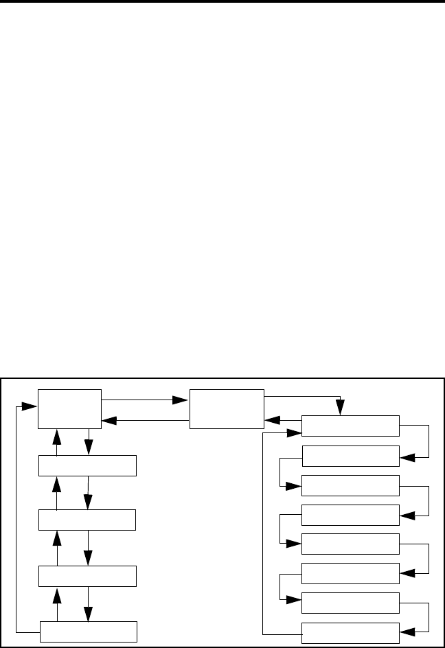
Menu Structure
When the Keypad Programming mode is selected by pressing the
option switch and entering the password, “Pgm” is displayed along with
the first menu parameter “RAD PARM”. The following flowchart shows
the keypad programming mode menu structure for this radio.
51xx Portable Keypad Programming Flowchart
The information which follows describes how the various parame-
ters are programmed. When programming is complete, exit the keypad
RAD
PARM
Clone?
Rx Freq
Tx Freq
Rx CG/NAC
Tx CG/NAC
Tx Power
TOT On-Off
*
#
Zone No. ZONE x
F3 key CHAN xx
#
*#
#
#
#
#
#
#
Wide/Nar Band
#
Tx Timer
Penalty Timer
Conver. Timer
#
#
#
*
*
*
#

CONVENTIONAL FEATURES
42
programming mode by turning power off. Do not turn power on again for
a short time so that the radio has time to copy the settings to memory.
Cloning
The cloning mode is used to program one transceiver with another
with identical information. A special cloning cable is required to connect
the transceivers together. To enter this mode, on the master (sending)
radio, press the # (pound) key with “RAD PARM” displayed. The clone
mode is then indicated by “CLONE?”. To return to “RAD PARM”
without cloning, press the key. To clone a radio, connect the cloning
cable, power up the slave (receiving) radio, and press the F4 key on the
master (sending) radio. When cloning is successfully completed, “RAD
PARM” is again displayed. Encryption keys are not transferred.
Timer Programming
The menus to program the following timers are accessed by repeat-
edly pressing the # key with “RAD PARM” displayed. To return to the
previous adjustment, press the key.
TX TMR - Programs the transmit time-out timer (see page 22). Press
the Up/Down select switch to decrement/increment the timer in 15-
second steps (“0” disables it). When the desired value is displayed,
store it by pressing the F4 key.
PEN TMR - Programs the penalty timer (see page 33). Press the Up/
Down select switch to decrement/increment the timer in 15-second
steps (“0” disables it). When the desired value is displayed, store it by
pressing the F4 key.
CONV TMR - Programs the conversation timer (see page 33). Press
the Up/Down select switch to decrement/increment the timer in 30-
second steps (“0” disables it). When the desired value is displayed,
store it by pressing the F4 key.
*
*

CONVENTIONAL FEATURES
43
Channel Parameter Programming
Zone Selection
The zone containing the channel to be programmed must be selected
if applicable. To do this, with “RAD PARM” displayed press the key corre-
sponding to the zone containing the channel. Alternatively, press the Up/
Down select switch to scroll through the programmed zones and the “RAD
PARM” selection. The zone selection mode is indicated by “ZONE x”. To
return to “RAD PARM”, press the F3 key. To proceed to channel param-
eter programming described in the next section, press the # key.
Channel Selection
The channel to be programmed must be selected. To do this, press
the # key with “ZONE x” displayed as described in the preceding section.
The display then indicates “CHAN xx”. Then to select the desired
channel, press the Up/Down select switch to scroll through the
programmed channels or enter the channel number directly using the
number keys. Disabled or SMARTNET/SmartZone channels cannot be
selected.
To exit back to the “ZONE x” display, press the key with
“CHAN xx” displayed. To save the selection and proceed with the
channel parameter programming described in the next section, press the
F4 or # key.
Channel Parameter Programming
After selecting the channel to be programmed as described in the
preceding section, the following channel parameters can be programmed.
To scroll through these parameters, press the F4 or # key with “CHAN
xx” displayed. To go back to the previous field, press the key. The
squelch control parameters are unique to the type of conventional channel
selected (analog or Project 25).
Channel Spacing - Selects either “WIDE” or “NARROW” band channel
spacing on analog channels only. Press the Up/Down select switch to
*
*

CONVENTIONAL FEATURES
44
toggle between “WIDE” and “NARROW”, and when the desired setting
is displayed, save it and proceed to the next parameter by pressing the F4
or # key.
Receive Frequency - When the Rx icon is indicated to the left of Pgm
and a frequency or eight zeros is displayed, the receive channel frequency
can be programmed. Press the F3 key to clear the current frequency and
then type in the new frequency. When the desired frequency is displayed,
save it and proceed to the next parameter by pressing the F4 or # key.
Transmit Frequency - When the Tx icon is indicated to the left of Pgm
and a frequency or eight zeros is displayed, the transmit frequency is
programmed the same as the Receive Frequency above.
Squelch Control (Analog Channels)
Receive CTCSS/DCS - When “TN xxxx” or “DIG xxx” is displayed
with the Rx icon indicated to the left of Pgm, the receive Call Guard
(CTCSS/DCS) code can be programmed. Press the F3 key to clear the
current code and toggle between the CTCSS (tone) and DCS (digital)
modes. Press the Up/Down select switch to scroll through the avail-
able codes. When the desired code is displayed, save it and proceed to
the next parameter by pressing the F4 or # key.
Transmit CTCSS/DCS - When “TN xxxx” or “DIG xxx” is
displayed with the Tx icon indicated to the left of Pgm, the transmit
Call Guard (CTCSS/DCS) code can be programmed the same as the
Receive CTCSS/DCS above.
Squelch Control (Project 25 Channels)
Receive NAC - When “NAC xxx” is displayed with the Rx icon indi-
cated to the left of Pgm, the receive Network Access Code (NAC)
can be programmed. This can be any number from 0-4095. Press the
F3 key to clear the current code and then enter the desired code using
the number keys. When the desired code is displayed, save it and
proceed to the next parameter by pressing the F4 or # key.

CONVENTIONAL FEATURES
45
Transmit NAC - When “NAC xxx” is displayed with the Tx icon
indicated to the left of Pgm, the receive NAC can be programmed the
same as the Receive NAC described above.
Transmit Power Level - When any of the following indications are
displayed, the power output level for the channel can be programmed.
Press the Up/Down select switch to scroll through the choices. When the
desired setting is displayed, save it and proceed to the next parameter by
pressing the F4 or # key.
•POWER HI - High transmit power
•POWER LO - Low transmit power
•POWER SW - Switchable power selectable by the High/Low power
switch. This choice is not available if that switch is not
programmed.
Time-Out Timer - When “TOT ON” or “TOT OFF” is displayed, the
time-out timer can be enabled or disabled on the current channel. Press
the Up/Down select switch to toggle between the on and off mode. To
return to the “CHAN xx” display, press the F4 or # key.
Programming Additional Channels and Exiting Programming Mode
•To program another channel in the current zone, press the F4 or # key
to redisplay “CHAN xx” and then repeat starting with “Channel
Selection” on page 43.
•To program channels in another zone, press the key with “CHAN
xx” displayed to display “ZONE x” and repeat this procedure starting
with “Zone Selection” on page 43.
•If programming is complete, exit the keypad programming mode by
turning power off. Do not turn power on again for a short time to allow
the radio time to copy the settings into memory.
*

SMARTNET/SMARTZONE FEATURES
46
SMARTNET/SMARTZONE FEATURES
Introduction
The following information describes features unique to the
SMARTNET and SmartZone operating mode (see brief description on
page 29). Refer to the preceding “Conventional Features” section for
information on features common to that operating mode, and to the
“General Information” section starting on page 18 for information on
features common to all operating modes.
Viewing Unit ID
Each radio in a SMARTNET system is identified with a six-digit
system ID and Unit ID. To display these IDs, make sure that a
SMARTNET channel is selected and then turn power off and then on
again. The system ID is briefly displayed as SYxxxxxx followed by the
Unit ID as EDxxxxxx.
Standard Group Calls
Standard group calls are between you and another mobile, group of
mobiles, or a control station (a radio at a fixed location). Most calls you
make will probably be this type.
Placing a Standard Group Call
1. Turn power on and set the volume as described on page 18. Select the
channel programmed for the talk group you want to call (see page 21).
A regular or announcement talk group can be selected.
2. If encryption is used, it may be automatically selected. If not, select the
secure mode if desired by pressing the Clear/Secure option switch.
Refer to “Secure Communication” on page 28 for more information.
3. Press the PTT switch and when the alert tone sounds, begin talking.
Other indications that may occur are as follows:

SMARTNET/SMARTZONE FEATURES
47
•If in the secure mode and your transceiver does not have the proper
encryption key, “KEYFAIL” is displayed and the call must be made
in the clear mode (selected by the Clear/Secure option switch if
enabled on the channel).
•If the busy tone sounds and “BUSY” is displayed, the system is busy.
Release the PTT switch and wait for the call back tone to sound. Then
press the PTT switch within 3 seconds and begin talking.
•If a continuous tone sounds while pressing the PTT switch and “NO
SYS” is displayed, you may be out-of-range. Drive closer or away
from shielding objects and try again.
•If your unit ID is invalid, the call is being made to an invalid group
ID, or group calls are not allowed, “REJECT” is displayed and an
alert tone sounds.
•If an attempt is made to select the secure mode and there is no avail-
able secure channel, “NO SEC” is flashed and the call continues in the
clear mode.
•If an attempt is made to change from the secure to the clear mode and
this is not permitted, “SEC ONLY” is displayed and the call continues
in the secure mode.
Receiving a Standard Call
Group calls are automatically received if a SMARTNET/SmartZone
channel is selected. The display alternately indicates the unit ID and talk
group when a call is received (if enabled by programming).
Enhanced Private Conversation Calls
General
Private calls allow you to place a call to a specific mobile unit.
Either the Enhanced Private Conversation™ or Private Conversation II™
modes may be programmed depending on the capabilities of the radio

SMARTNET/SMARTZONE FEATURES
48
system. The Enhanced Private Conversation mode is described in the
following information, and the Private Conversation II mode is described
starting on page 51.
The Private Call option switch is required to place these calls, and
either that switch or the Call Response option switch is required to
receive them. Proceed as follows.
Placing an Enhanced Private Conversation Call
This call can be initiated by selecting the unit ID from a call list (list
entry) or by directly entering it using the keypad (direct entry). Direct
entry is available with full keypad (17-key) models only. Proceed as
follows: List Entry Method
1. With a SMARTNET/SmartZone channel selected, momentarily press
the Private Call option switch. The tag (alias) of the last ID called is
displayed if it matches an ID in your call list. Otherwise, the last ID
called is displayed.
2. Enter the two-digit index of the desired ID if you know it or scroll
through the list using the Up/Down switch until you find the desired ID.
Press the F3 key to cancel the call.
3. Press the PTT switch to initiate the call. The display then indicates the
alias of the destination radio. If the entered digits do not correspond to
a valid list entry, “INVALID” is displayed and an error tone sounds.
Proceed to the bulleted list following the next method for other condi-
tions that may occur next.
Direct Entry Method (Full Keypad Models Only)
1. With a SMARTNET/SmartZone channel selected, press and hold the
Private Call option switch until a tone sounds (approximately 1
second). The last ID called is displayed.

SMARTNET/SMARTZONE FEATURES
49
2. Using the 0-9 keys, enter the ID (all six digits) of the mobile unit you
are calling. To erase the last digit, press the Down switch, and to cancel
the call, press the F3 key.
3. Press the PTT switch to initiate the call. If the entered ID did not contain
six digits, “INVALID” is momentarily displayed, an error tone sounds,
and the call is not initiated. If the entered ID is valid, the display indi-
cates the alias of the ID if it matches an ID in your call list. Otherwise,
the ID you entered continues to be displayed. Any of the following
conditions may then occur:
•If the radio you are calling is on the air, “WAIT” is displayed and tele-
phone type “ringing” is heard for 20 seconds or until the called party
answers.
•If the called party answers and the call is successful, the person’s
voice is heard and the call is carried on the same as a group call. To
end the call at any time, press the F3 key.
•If the called party does not answer within 20 seconds, “NO ANS” is
displayed and a continuous tone sounds. End the call by pressing the
F3 key.
•If the called radio is not in service, no ringing is heard, “NO ACK” is
displayed, and a continuous tone sounds. End the call by pressing the
F3 key.
•If neither your radio nor the radio being called is authorized to make
unit-to-unit calls, “REJECT” is displayed and a continuous tone
sounds. End the call by pressing the F3 key.
•If the called party answers but the radio system is busy, four low tones
sound and “BUSY” is displayed. When the system is no longer busy,
the call back tone sounds.
•If in the secure mode and your transceiver does not have the proper
encryption key, “KEYFAIL” is displayed and the call must be made

SMARTNET/SMARTZONE FEATURES
50
in the clear mode (selected by the Clear/Secure option switch if
enabled on the channel).
•If an out-of-range condition exists or the radio system is not in
service, “LOST CALL” is displayed and a continuous tone sounds.
End the call by pressing the F3 key.
Receiving an Enhanced Private Conversation Call
These calls are automatically received if a SMARTNET/SmartZone
channel is selected. Proceed as follows:
1. When a call is received, a recurring unit call tone (three beeps) sounds
for up to 20 seconds and “CALL” is displayed.
2. To answer the call, press the Private Call option switch and then the
PTT switch and begin talking. The alias of the incoming call is
displayed if the ID is in your call list. Otherwise, the unit ID is
displayed. NOTE: If the Private Call option switch is not pressed before
the PTT switch, a group call is transmitted on the selected group.
•To end the call when the conversation is complete or at any other time,
press the F3 key.
•If unit-to-unit (private) calls are not permitted (Private Call switch not
programmed), press the Call Response option switch, if available, to
answer the call.
•If the call is not answered within 20 seconds, it is automatically
terminated.
•If the radio system is busy, four low tones sound and “BUSY” is
displayed. When the system is no longer busy, the call back tone (four
beeps) is heard and your radio automatically starts transmitting. Press
the PTT switch to continue the call.

SMARTNET/SMARTZONE FEATURES
51
Private Conversation II Calls
General
Private calls allow you to place a call to a specific mobile unit.
Either the Enhanced Private Conversation™ or Private Conversation II™
modes may be programmed depending on the capabilities of the radio
system. Operation in the Enhanced Private Conversation mode was
described starting on page 47, and operation in the Private Conversation
II mode is described in the following information.
The Private Call option switch is required to place these calls, and
either that switch or the Call Response option switch is required to
receive them. Proceed as follows.
Placing a Private Conversation II Call
This call can be initiated by selecting the unit ID from a call list (list
entry) or by directly entering it using the keypad (direct entry). Direct
entry is available with full keypad (17-key) models only. Proceed as
follows:
List Entry Method
1. With a SMARTNET/SmartZone channel selected, momentarily press
the Private Call option switch. The tag (alias) of the last ID called is
displayed if it matches an ID in your call list. Otherwise, the last ID
called is displayed.
2. Enter the two-digit index of the desired ID if you know it or scroll
through the list using the Up/Down switch until you find the desired ID.
Press the F3 key to cancel the call.
3. Press the PTT switch to initiate the call. The display then indicates the
alias of the destination radio. Wait approximately 1 second and then
begin talking. Proceed to the bulleted list which follows the next
method for conditions that may then occur.

SMARTNET/SMARTZONE FEATURES
52
Direct Entry Method (Full Keypad Models Only)
1. With a SMARTNET/SmartZone channel selected, press and hold the
Private Call option switch until a tone sounds (approximately 1
second). The last ID called is displayed.
2. Using the 0-9 keys, enter the ID (all six digits) of the mobile unit you
are calling. To erase the last digit, press the Down switch, and to cancel
the call, press the F3 key.
3. Press the PTT switch to initiate the call. If the entered ID did not contain
six digits, “INVALID” is momentarily displayed, an error tone sounds,
and the call is not initiated. If the entered ID is valid, the display indi-
cates the alias of the ID if it matches an ID in your call list. Otherwise,
the ID you entered continues to be displayed. Any of the following
conditions may then occur.
•If in the secure mode and your transceiver does not have the proper
encryption key, “KEYFAIL” is displayed and the call must be made
in the clear mode (selected by the Clear/Secure option switch if
enabled on the channel).
•If the called party answers and the call is successful, the person’s
voice is heard and the call is carried on the same as a group call. To
end the call at any time, press the F3 key.
•If the radio system is busy, four low tones sound and the “BUSY” is
displayed. When the system is no longer busy, the call back tone (four
beeps) is heard and a channel is automatically acquired. Press the PTT
switch to continue the call.
Receiving a Private Conversation II Call
Unit-to-unit calls are automatically received if a SMARTNET/
SmartZone channel is selected. Proceed as follows:
1. When a call is received, an alert tone sounds and the caller’s voice is
heard. While voice is heard, “CALL” is displayed.

SMARTNET/SMARTZONE FEATURES
53
2. To answer the call, press the Private Call option switch and then the
PTT switch and begin talking. The alias of the incoming call is
displayed if the ID is in your call list. Otherwise, the unit ID is
displayed. NOTE: If the Private Call option switch is not pressed before
the PTT switch, a group call is transmitted on the selected group.
•To end the call when the conversation is complete or at any other time,
press the F3 key. If the call is not answered within 20 seconds, it is
automatically terminated.
•If private calls are not permitted (Private Call switch not
programmed), press the Call Response option switch, if available, to
answer the call.
Telephone Calls
General
Telephone calls allow you to place and receive calls over the public
telephone system using your transceiver. If your transceiver is
programmed for telephone calls (Phone option switch programmed), they
are placed and received as follows:
Placing a Telephone Call
Telephone calls can be placed by selecting the number from a
preprogrammed phone number list (list entry) or by directly entering it
using the keypad (direct entry). Direct entry is available with full keypad
(17-key) models only. Proceed as follows:
List Entry Method
1. With a SMARTNET/SmartZone channel selected, momentarily press
the Phone option switch. The display indicates the alias of the last
called telephone number if it is in your phone number list. Otherwise,
the last eight digits of the last called telephone number are displayed.

SMARTNET/SMARTZONE FEATURES
54
2. Enter the index of the desired telephone number if you know it or scroll
through the list using the Up/Down switch until you find the desired
number. Press the F3 key to cancel the call.
3. Press the PTT switch to initiate the call. The display indicates “WAIT”
while the connection to the phone system is occurring. Once connected,
the normal dial tone is heard and the alias of the number being called is
displayed. The radio then automatically dials the telephone number and
the normal ringing or busy tone is heard. Proceed to the bulleted list
which follows the next method for conditions that may then occur.
Direct Entry Method (Full Keypad Models Only)
1. With a SMARTNET/SmartZone channel selected, press and hold the
Phone option switch until a tone sounds (approximately 1 second). The
display indicates the alias of the last called telephone number if it is in
your phone number list. Otherwise, the last eight digits of the last called
telephone number are displayed.
2. Enter the number using the 0-9, , and # keys. To enter a pause (indi-
cated by “P”), press and then #. To erase the last digit, press the
Down switch. The number scrolls to the left in the display so that the
eight right-most digits are always displayed. Numbers up to 16 digits
(including pauses) can be entered. Press the F3 key to cancel the call.
3. Press the PTT switch or the F4 key to initiate the call. The display indi-
cates “WAIT” while the connection to the phone system is occurring.
Once connected, the normal dial tone is heard and the alias of the
number being called is displayed. The radio then automatically dials the
telephone number and the normal ringing or busy tone is heard. Any of
the following conditions may then occur.
•After the called party answers, press the PTT switch to talk and
release it to listen. You cannot talk and listen at the same time because
the radio cannot transmit and receive at the same time. Each time the
PTT switch is released, a tone is heard by the other party that indicates
when a response can be made. To end the call when the conversation
is complete or at any other time, press the F3 key.
*
*

SMARTNET/SMARTZONE FEATURES
55
•If the selected number is not valid, “INVALID” is momentarily
displayed, an error tone sounds, and the call is not initiated. Select a
valid number.
•If enabled by system operator programming, a number can be dialed
during a call by simply holding down the PTT switch and dialing the
number.
•If an out-of-range condition exists or the radio system is not in
service, “NO PHONE” is displayed and a continuous tone sounds.
End the call by pressing the F3 key.
•If you are not authorized to make telephone calls, “REJECT” is
displayed and a continuous tone sounds. End the call by pressing the
F3 key.
•If the radio system is busy, “BUSY” is displayed and a busy tone
sounds. The call automatically proceeds when the radio system
becomes available. If the call is ended before it proceeds, your
position in queue is lost.
•If in the secure mode and your transceiver does not have the proper
encryption key, “KEYFAIL” is displayed and the call must be made
in the clear mode (selected by the Clear/Secure option switch if
enabled on the channel).
Answering a Telephone Call
Telephone calls are automatically received if a SMARTNET/
SmartZone channel is selected. Proceed as follows:
1. When a telephone call is received, “ringing” similar to a standard tele-
phone is heard and the display indicates “PHONE”.
2. To answer the call, press the Phone option switch and then press the
PTT switch to talk and release it to listen.

SMARTNET/SMARTZONE FEATURES
56
3. To end the call when the conversation is complete or at any other time,
press the F3 key. Also press the F3 key to ignore an incoming call and
end it without answering.
Call Alert
The Call Alert™ feature allows pages to be sent and received.
Proceed as follows:
Sending a Page
Pages can be placed by selecting the unit ID from a preprogrammed
list (list entry) or by directly entering it using the keypad (direct entry).
Direct entry is available with full keypad (17-key) models only.
List Entry Method
1. With a SMARTNET/SmartZone channel selected, momentarily press
the Call Alert option switch. The tag (alias) of the last ID called is
displayed if it matches an ID in your call list. Otherwise, the last ID
called is displayed.
2. Enter the index of the desired ID if you know it or scroll through the list
using the Up/Down switch until you find the desired ID. Press the F3
key to cancel the call.
3. Press the PTT switch to send the page. The display then indicates the
alias of the radio being paged. Proceed to the bulleted list which follows
the next method for conditions that may then occur.
Direct Entry Method (Full Keypad Models Only)
1. With a SMARTNET/SmartZone channel selected, press and hold the
Call Alert option switch until a tone sounds (approximately 1 second).
The last ID called or paged is displayed.
2. Using the 0-9 keys, enter the 6-digit ID of the unit you are calling. To
erase the last digit, press the Down switch or press the F3 key to cancel
the page.

SMARTNET/SMARTZONE FEATURES
57
3. Press the PTT switch to send the page. If the entered ID is invalid,
“INVALID” is momentarily displayed and the page is not sent. If the
entered ID is valid, the display indicates the alias of the ID if it matches
an ID in your call list. Otherwise, the ID you entered continues to be
displayed. The page is then sent and any of the following conditions
may then occur.
•If the radio you are paging is on the air and received your page, a
signaling success tone (six beeps) sounds. The alias of the selected
channel is then displayed continuously.
•If the radio you are paging is not in service, a tone sounds and “NO
ACK” is displayed after trying for 6 seconds. Press the F3 key to cancel
the page or try again.
Answering a Page
1. When a page is received, the display indicates “PAGE” and a recurring
received page tone sounds (five beeps) sounds.
2. To clear and ignore the page, press the F3 key. NOTE: If the F3 key is
programmed for the Private Call function, it will not clear the page.
3. Answering a page is the same as placing a private call. Therefore, press
the Private Call option switch and follow the instructions for placing a
private call on page 48 or page 51, whichever is applicable.
Messaging
The messaging feature allows preprogrammed messages to be sent
to your dispatcher. Up to 16 messages can be preprogrammed, and they
are identified by a tag (alias). If a Message option switch is programmed,
messages are sent as follows:
1. Momentarily press the Message option switch. The alias of the last
message sent is displayed.

SMARTNET/SMARTZONE FEATURES
58
2. Enter the index of the desired message if you know it or scroll through
the list using the Up/Down switch until you find the desired message.
Press the F3 key to cancel the message.
3. Press the PTT switch to send the message. When the message is
received and acknowledged by the dispatcher, a signaling success tone
(six beeps) sounds and the display returns to the normal channel indi-
cation. If there is no acknowledgment after 6 seconds, a tone sounds
and “NO ACK” is displayed. Press the F3 key to return to normal oper-
ation.
Sending Status Conditions
The status feature allows you to send your current status to your
dispatcher. Up to eight status conditions can be preprogrammed, and they
are identified by an alias (name). If the Status option switch is
programmed, status conditions are sent as follows:
1. Momentarily press the Status option switch. The alias of the last status
sent is displayed.
2. To change the displayed status, enter the index of the desired status if
you know it or scroll through the list using the Up/Down switch until
you find the desired status. Press the F3 key to cancel this function.
3. Press the PTT switch to send the status. When the message is received
and acknowledged by the dispatcher, a signaling success tone (six
beeps) sounds and the display returns to the normal channel indication.
If there is no acknowledgment after 6 seconds, a tone sounds and “NO
ACK” is displayed. Press the F3 key to return to normal operation.
Emergency Alarm and Emergency Call
Emergency alarms and emergency calls are separate functions that
can be individually programmed on SMARTNET/SmartZone channels.
The Emergency switch is pressed to initiate these features. This switch is
the orange button located next to the antenna connector.

SMARTNET/SMARTZONE FEATURES
59
An emergency alarm is a special data transmission to alert your
dispatcher of an emergency situation, and an emergency call is an urgent
request for access to a voice channel. The emergency alarm and call are
transmitted on the emergency talk group or announcement group that has
been preprogrammed by your system operator on the currently selected
channel. Proceed as follows:
1. To transmit an emergency alarm, select a SMARTNET/SmartZone
channel that has that feature enabled and then press the Emergency
option switch.
2. The emergency alarm is then transmitted and “EMERGNCY” is
indicated in the display for a short time. Transmitting continues until an
acknowledgment is received (indicated by two beeps) or the
programmed number of attempts have occurred. Silent operation may
also be programmed in which case no audio or visual indication of the
alarm condition occurs.
3. To transmit an emergency call, press the Emergency option switch with
a SMARTNET/SmartZone channel selected that has that feature
enabled. Then manually press the PTT switch and begin speaking as
with a standard call. All calls that follow are then emergency calls and
they occur on the emergency talk group.
4. To exit the emergency mode, power must be turned off and then on
again.
Failsoft Operation
If a failure occurs in the SMARTNET/SmartZone system so that it
cannot be used, the transceiver automatically enters the failsoft mode.
When this mode is selected, the display alternately indicates “FAIL-
SOFT” and the alias of the selected channel.
When in the failsoft mode, operation is in the conventional mode on
a preprogrammed failsoft channel. If a transmission is attempted before a
failsoft channel is located, a continuous tone sounds until the PTT switch

SMARTNET/SMARTZONE FEATURES
60
is released. When the radio system returns to normal operation, this
condition is automatically detected and normal operation resumes.
SMARTNET/SmartZone Scanning
Scanning on a SMARTNET/Smartzone channel is similar to the
standard and radio wide scanning described starting on page 23. Each
channel can be programmed with a different scan list that includes up to
16 channels, one of which can be a priority channel. These scan lists are
user programmable if the Scan Edit option switch is programmed, and
nuisance channels can be temporarily deleted (see page 26).
Scanning is enabled/disabled by the Scan option switch. In addition,
channels can be programmed so that scanning automatically starts when-
ever the channel is selected. Scanning is temporarily disabled and
“Scan” turns off if a channel is selected that has scanning disabled. Then
when a channel is selected again that permits scanning, it is automatically
re-enabled.
In addition to calls on channels in the scan list, pages, private calls,
and telephone calls are received while scanning. Messages on the priority
channel are received while listening to lower priority messages. However,
private and telephone calls are not interrupted by calls on the priority
channel.
Dynamic Regrouping
The dynamic regrouping feature allows a dispatcher to switch users
to a dynamically defined channel to receive an important message.
Dynamic regrouping operates as follows:
1. When this command is received, the alternating dynamic regrouping
tone sounds, the transceiver automatically changes to the regrouping
channel, and the display alternately indicates “REGROUP” and the
alias of the selected channel. All transmitting and receiving then occurs
on this channel.

SMARTNET/SMARTZONE FEATURES
61
2. To reset all talk and announcement groups to normal so that only the
designated regrouping channel is on the dynamic group, manually
select the designated regrouping channel if you know it. If this channel
is not selected or there is no designated regrouping channel, all trans-
missions occur on the dynamically assigned group regardless of which
channel is selected, and the regrouping tone sounds each time the PTT
switch is pressed.
3. When regrouping is canceled by the dispatcher, transceiver operation
returns to normal.
SmartZone Features
Introduction
As described starting on page 28, the SmartZone® mode provides
wide area coverage by allowing roaming between SMARTNET and
conventional sites. SmartZone operation is the same as SMARTNET with
the following additional features.
Determining Current Site
To determine the current radio site, momentarily press the Site
Search option switch (if programmed). If currently registered on a site,
“SITE x” is displayed, where “x” is the site number. The display then
indicates the RSSI (Receive Signal Strength Indicator) value of the
current site as “RSSI x” and then returns to displaying the channel alias.
Searching For a New Site
To search for a new site, press the Site Search option switch (if
programmed) to toggle through the available sites. “RSSI x” is displayed
as just described and the channel alias is then displayed.
Locking/Unlocking a Site
It is sometimes desirable to stay on the current site regardless of
signal level. To lock the radio on the current site so that it does not search

MISCELLANEOUS
62
for another, press the Site Lock option switch (if programmed). The
display then momentarily indicates “LOCK x” to indicate that the current
site is locked (“x” is the current site number). To unlock the site, press the
Lock switch again and “UNLOCK” is momentarily displayed.
When locked on a site, it is still possible to search for a different site
using the site search function described in the preceding section. When a
new site is found, the radio is then locked on that site.
MISCELLANEOUS
Supervisory Tones
Single Beep (Alert Tone)
•Power was turned on and a successful power-up sequence occurred (see
page 18).
•The time-out timer is about to expire or the penalty timer has expired
(page 22 and page 33).
•The conversation timer is about to expire (page 34).
•The system received your page but the paged mobile is not on the air
(page 56).
•Telephone interconnect is not operational (page 53).
Continuous Tone (Invalid or No Acknowledge Condition)
•A transmission is being attempted on an unprogrammed channel or a
conventional channel programmed as receive-only.
•The transmitter is disabled by the busy channel lockout feature
(page 32).
•The transmitter has been disabled by the time-out timer feature
(page 22).
•The transmitter has been disabled by the conversation timer (page 34).
•An out-of-range condition exists (SMARTNET/SmartZone only).
•A transmission is being attempted before the penalty timer has expired
(page 33).

MISCELLANEOUS
63
•Dynamic regrouping has been exited but the dynamic regrouping
channel is still selected (page 60).
•The paged mobile did not acknowledge the page (page 56).
•The message that was sent has not been acknowledged (page 57).
•The status condition that was sent has not been acknowledged
(page 58).
Single Short Medium-Pitch Tone
•A valid key has been pressed.
Single Short Low-Pitch Tone
•An invalid key has been pressed.
Six Beeps (Recurring)
•The page was received (page 56).
Three Beeps (Recurring)
•A unit-to-unit call was received (page 47).
Six Beeps
•The paged radio received the page and acknowledged it (page 56).
•The message that was sent has been received and acknowledged
(page 57).
•The status condition that was sent has been received and acknowledged
(page 58).
Two Beeps
•The emergency alarm condition was acknowledged (page 58).
Gurgle-Like Tone
•Dynamic regrouping has occurred (page 60).

MISCELLANEOUS
64
•Dynamic regrouping has occurred but the regrouping channel is not
selected (page 60).
Four Low Tones (Busy Signal)
•The radio system is busy or a busy condition exists when making a
telephone call.
Four Alternating High and Low Tones
•A channel is available after a busy condition occurred (SMARTNET/
SmartZone only).
Rechargeable Battery Pack
WARNING
Do not dispose of the battery pack in fire because it may explode. The
nickel metal-hydride (NiMH) battery pack used by this radio must be
disposed of in accordance with local regulations. Do not short the termi-
nals because the battery may become very hot.
Battery Life
With proper care, the nickel metal-hydride (NiMH) battery pack
used by this radio should provide excellent service. When the pack no
longer holds a charge or provides only a very short operating time, it must
be replaced with a new unit.
Typical operating time before recharging is required is approxi-
mately 13 hours with the standard 3000 mAH battery. This assumes that
the transceiver is transmitting at high power 5% of the time, receiving
and producing audio 5% of the time, and in the standby mode (receive
with audio muted) 90% of the time. If the low-power mode is selected or
different times are spent in these modes, operating time varies accord-
ingly. The charge of the battery and ambient temperature also affect oper-
ating time.

MISCELLANEOUS
65
NOTE: Be sure to turn transceiver power off before removing the battery
pack. Failure to do so may result in the current settings not being saved
in memory.
Recharging
Recharging is required when the green indicator on the top panel
flashes when not receiving a signal, or when the red indicator flashes
when transmitting. In addition, a chirp may sound when transmitting and
receiving. Refer to “Low Battery Indication” on page 21 for more
information.
The pack can be recharged while still on the transceiver or it can be
charged separately. To remove the battery pack from the transceiver,
press the spring-loaded release button on the end outward and slide the
battery off. A new battery pack must be charged before use.
Battery Care
One cause of shortened battery life is repeated deep discharge.
Therefore, it is recommended that the battery be recharged as soon as
practical after the low-battery indication appears (see preceding informa-
tion). Do not continue using the transceiver until the battery is completely
discharged. Another cause of reduced battery life is operation at tempera-
ture extremes. It is also good practice not to regularly leave a pack in the
charger for extended periods after it is completely charged.
It is possible that the pack could develop a characteristic called
“memory” although these packs are designed to minimize that problem.
When a pack has this problem, it acts as if it is totally discharged even
though it has greater capacity. This can be caused by discharging a pack
only slightly before recharging, charging at too high a temperature, or
extended storage. If a pack develops this problem, it can usually be
corrected by performing three discharge/charge cycles.

MISCELLANEOUS
66
System Operator Programming
As noted several times in this manual, programming determines the
availability and specific operation of many features. This usually refers to
the programming performed by your system operator when the radio was
set up, not to any programming that you can perform. If a feature is
controlled by a front panel option switch and that switch is not available,
it is probably not available or in a fixed condition. Contact your system
operator for more information on how programmable functions have been
set for your application. If the Keypad Programming option switch is
available, you can reprogram some conventional channel parameters.
Refer to “Keypad Programming” on page 40 for more information.
Speaking Into Microphone
For best results, hold the speaker grille about 1-2 inches from your
mouth and speak at a normal conversational level. Do not shout since it
distorts your voice and does not increase range. Make sure that the PTT
(push-to-talk) switch is pressed before you begin to speak and released as
soon as the message is complete.
Operation At Extended Range
When approaching the limits of radio range, the other party may not
be able to hear your transmissions and there may be an increase in back-
ground noise when messages are received. You may still be out of range
even though you can hear a message. The reason for this is that the signal
you are receiving is usually transmitted at a higher power level than the
one transmitted by your transceiver. Communication may be improved by
moving to higher ground or away from shielding objects such as tall
buildings or hills.
Licensing
A government license is usually required to operate this transceiver
on the air. Your system operator will normally handle the licensing
requirements.

MISCELLANEOUS
67
Transceiver Service
If the transceiver begins operating improperly, try turning power off
and then on again to reset the logic. Also make sure that the battery is
fully charged and in good condition. Some other possible causes of
improper operation are as follows. If the transceiver still does not operate
properly, return it to your system operator for service.
The expected signal is not being received:
•Repeater talk-around may be selected (see page 34).
•The correct channel but wrong zone may be selected (see page 21).
•Keypad modified Call Guard coding may be selected. Press the “0”
key to see if operation returns to normal (see page 32).
•If scanning, the correct scan list may not be selected or the channel
may have been deleted from the scan list (see page 35).
The radio does not transmit on the selected channel:
•The channel may be busy (green indicator lighted) and the trans-
mitter disabled by the busy channel lockout feature (see page 32).
•If the transmitter was just keyed for an extended time, it may have
been disabled by the time-out timer and penalty timers (see pages 22
and 33).
The receive audio signal is garbled:
•The correct encryption key may not be loaded (see page 28). Contact
your system operator for assistance.
NOTE: There are no user-serviceable components inside this transceiver.
Altering internal adjustments can cause illegal emissions, void the war-
ranty, and result in improper operation that can seriously damage the
transceiver.

INDEX
68
INDEX
A
Accessory Connector 16
Alias 21
ANI Signaling 38
Antenna Connector 15
B
Backlight 20
Battery 16
Care 65
Life 64
Recharging 65
Busy Channel Lockout 30, 32, 38
Busy Indicator 31
C
Call Alert (Paging) 56
Call Guard Squelch 32
Changing Code 33
Channel Number 30
Channel Select 21
Channel Switch 15
Conventional Mode 28
Conversation Timer 34
CTCSS Signaling 32
D
DCS Signaling 32
DIG Indication 28
Display 17
Display Mode Select 30
DTMF Keypad 14
DTMF/ANI Signaling 38
Dynamic Regrouping 60
E
Emergency Alarms 58
Emergency Calls 58
Emergency Switch 15
Enh. Priv. Conversation Call
Placing 48
Receiving 50
Extended Range Operation 66
F
F1/F3 Switches 20
Failsoft Operation 59
Features
Conventional 6, 29
General 6
Project 25 39
SMARTNET 46
SmartNet/SmartZone 7
SmartZone 61
Front Display 14
G
Group IDs
Project 25 39
H
Home Zone 22
I
Indicator
Encryption 28
Individual Calls
Project 25 40
Individual ID
Project 25 39
K
Keypad Lock 21

INDEX
69
L
Licensing 66
Low Battery 21
M
Messaging 57
Microphone 13
Mode
Conventional 28
SMARTNET/SmartZone 29
Monitor Mode 31
Monitoring Before Transmitting 30
N
NAC 39
Nuisance Channel Delete 26
O
On-Off/Volume 18
On-Off/Volume Control 15
Operating Modes 28
Option Switch 11, 15, 16, 20
Backlight 20
Call Alert 56
Call Response 50, 53
Clear/Secure 46
Displayed Information 30
Emergency 58
High/Low Power 34
Home Zone 22
Individual Calls 40
Keypad Lock 21
Message 57
Monitor 31
Normal/Selective 31, 32
Phone 53, 55
Priority 37
Private Call 48, 50, 51, 53, 57
Radio Wide Scan 24
Repeater Talk-Around 34
Scan 24, 36
Scan Edit 27
Site Lock 62
Site Search (SmartZone) 61
Status 58
Talk Group Select 39
Tones On-Off 23
Zone 22
Option Switches 14
P
Paging 56
Answering 57
Initiating 56
Password
Changing 19
Power-Up 19
Penalty Timer 33
Power Output Select 34
PRI Indication 36
Priority Calls
Conv 36
SmartNet 60
Priv. Conversation II Calls
Placing 51
Receiving 52
Private Calls 47
Programming 66
PTT Switch 16
R
Repeater Talk-Around 34
S
Safety Information 4
SCAN Indication 24
Scan List 25

INDEX
70
Channel Delete 26
Conventional Mode 35
Determining Channels in 25
Programming 26
Radio Wide Scan Mode 25
Selecting 35
Standard Scan Mode 25
Scan list 23
Scan Mode
Transmitting In 36
Scan Resume Delay 25
Scanning 23
Conventional 35
Radio Wide 23, 24
SmartNet 60
Standard 23, 24
SEC Indication 28
Secure Communication 28
Servicing 67
Site
Locking/Unlocking 61
Searching for 61
Site ID (SmartZone) 61
SMARTNET/SmartZone Mode 29
Speaker 13
Speaking Into Microphone 66
Standard Calls
Placing (Conv) 37
Placing (SMARTNET) 46
Receiving (Conv) 38
Receiving (SmartNet) 47
Status Messages 58
Supervisory Tones 62
T
Talk-Around, Repeater 34
Telephone Calls
Placing 53
Receiving 55
Time-Out Timer 22
Tone Enable/Disable 23
Tones 62
Transmit Disable On Busy 32
Transmitting, Scan Mode 36
Troubleshooting 67
U
Unit ID 18, 46
V
Voice Encryption 28
Volume Level, Setting 18
W
Warranty 3
Z
Zone Select 21

Part Number 002-5100-001
8-01hph Printed in U.S.A