E F Johnson 2425180 PTT 800 MHz SMR User Manual 050102 Service Manual Part 1 to FCC
E. F. Johnson Company PTT 800 MHz SMR 050102 Service Manual Part 1 to FCC
Contents
- 1. 022702 Operator Manual
- 2. 050102 Service Manual Part 1 to FCC
- 3. 050102 Service Manual Part 2 to FCC
- 4. Manual part 1
- 5. Manual part 2
050102 Service Manual Part 1 to FCC
Service Manualual
5100 SERIES PORTABLE
DIGITAL/ANALOG
VHF/UHF/800 MHz
7.2 VDC
5 & 1 W (VHF), 4 & 1 W (UHF), 3 W (800 MHz)
Part No. 242-51xx-xxx
First Printing
September 2001
PRELIMINARY

51xx SERIES PORTABLE
VHF/UHF/800 MHz
PROJECT 25 (DIGITAL) AND ANALOG
7.5 VDC
5 & 1 W (VHF), 4 & 1 W (UHF), 3 W (800 MHz)
Part No. 242-51xx-xxx
Copyright© 2001 by the E.F. Johnson Company
The E.F. Johnson Company, which was founded in 1923, provides wireless communication
systems solutions for public safety, government, and commercial customers. The company
designs, manufactures, and markets conventional and trunked radio systems, mobile and
portable subscriber radios, repeaters, and Project 25 digital radio products. E.F. Johnson is a
wholly owned subsidiary of Transcrypt International, Inc.
Viking Head/EFJohnson logo, Call Guard®, PCTrunk™, and PCTune™ are registered trade-
marks of the E.F. Johnson Company. SMARTNET™, SmartZone®, SecureNet™, Call Alert™,
Enhanced Private Conversation™, and Private Conversation II™ are trademarks of Motorola,
Inc. All other company and/or product names used in this manual are trademarks and/or reg-
istered trademarks of their respective manufacturer. The IMBE™ voice coding technology
embodied in this product is protected by intellectual property rights including patent rights of
Digital Voice Systems, Inc.
Information in this manual is subject to change without notice.

TABLE OF CONTENTS
ii September 2001
Part No. 001-5100-001
TABLE OF CONTENTS
1 GENERAL INFORMATION
1.1 SCOPE OF MANUAL. . . . . . . . . . . . . . . . . . . .1-1
1.2 TRANSCEIVER DESCRIPTION . . . . . . . . . . .1-1
General . . . . . . . . . . . . . . . . . . . . . . . . . . . . . . . . 1-1
Analog/Digital Operation . . . . . . . . . . . . . . . . . . 1-1
Operating Protocols . . . . . . . . . . . . . . . . . . . . . . 1-1
18-Key/6-Key Models . . . . . . . . . . . . . . . . . . . . 1-1
Systems, Channels, and Zones . . . . . . . . . . . . . . 1-1
Secure Communication . . . . . . . . . . . . . . . . . . . 1-2
Programming . . . . . . . . . . . . . . . . . . . . . . . . . . . 1-2
Alignment . . . . . . . . . . . . . . . . . . . . . . . . . . . . . . 1-2
1.3 PRODUCT WARRANTY . . . . . . . . . . . . . . . . .1-2
1.4 PART NUMBER BREAKDOWN. . . . . . . . . . .1-3
1.5 TRANSCEIVER IDENTIFICATION . . . . . . . .1-3
1.6 ACCESSORIES. . . . . . . . . . . . . . . . . . . . . . . . .1-3
1.7 FACTORY CUSTOMER SERVICE . . . . . . . .1-4
1.8 FACTORY RETURNS . . . . . . . . . . . . . . . . . . .1-5
1.9 REPLACEMENT PARTS. . . . . . . . . . . . . . . . .1-5
1.10 INTERNET HOME PAGE. . . . . . . . . . . . . . . . .1-5
2 OPERATION
2.1 FEATURES. . . . . . . . . . . . . . . . . . . . . . . . . . . . .2-1
General Featu res . . . . . . . . . . . . . . . . . . . . . . . . 2-1
Conventional Features . . . . . . . . . . . . . . . . . . . . 2-1
SMARTNET/SmartZone Features . . . . . . . . . . . 2-1
2.2 OPTION SWITCH FUNCTIONS . . . . . . . . . . .2-1
2.3 CONTROLS AND DISPLAY . . . . . . . . . . . . . .2-2
Front Panel Controls. . . . . . . . . . . . . . . . . . . . . . 2-2
Top Panel Controls . . . . . . . . . . . . . . . . . . . . . . . 2-3
Side Controls . . . . . . . . . . . . . . . . . . . . . . . . . . . 2-4
Display . . . . . . . . . . . . . . . . . . . . . . . . . . . . . . . . 2-4
2.4 GENERAL OPERATION . . . . . . . . . . . . . . . . .2-5
Introduction . . . . . . . . . . . . . . . . . . . . . . . . . . . . 2-5
Turning Power On and Setting Volume . . . . . . . 2-5
Power-Up Password . . . . . . . . . . . . . . . . . . . . . . 2-5
Backlight. . . . . . . . . . . . . . . . . . . . . . . . . . . . . . . 2-5
Option Switches . . . . . . . . . . . . . . . . . . . . . . . . . 2-6
Keypad Lock . . . . . . . . . . . . . . . . . . . . . . . . . . . 2-6
Low Battery Indication. . . . . . . . . . . . . . . . . . . . 2-6
Channel and Zone Selection. . . . . . . . . . . . . . . . 2-6
Home Zone . . . . . . . . . . . . . . . . . . . . . . . . . . . . . 2-7
Time-Out Timer . . . . . . . . . . . . . . . . . . . . . . . . . 2-7
Tone Enable/Disable . . . . . . . . . . . . . . . . . . . . . 2-7
Transceiver Operating Modes . . . . . . . . . . . . . . 2-7
Secure Communication . . . . . . . . . . . . . . . . . . . 2-8
2.5 SCANNING. . . . . . . . . . . . . . . . . . . . . . . . . . . . .2-8
Introduction . . . . . . . . . . . . . . . . . . . . . . . . . . . . 2-8
Standard Scanning . . . . . . . . . . . . . . . . . . . . . . . 2-8
Radio Wide Scanning . . . . . . . . . . . . . . . . . . . . . 2-8
Scan Resume Delay . . . . . . . . . . . . . . . . . . . . . . 2-9
Standard Mode Scan List . . . . . . . . . . . . . . . . . . 2-9
Radio Wide Mode Scan List. . . . . . . . . . . . . . . . 2-9
Determining Which Channels are in Scan List. . 2-9
Nuisance Channel Delete . . . . . . . . . . . . . . . . . . 2-9
Programming a Scan List . . . . . . . . . . . . . . . . . . 2-9
2.6 CONVENTIONAL FEATURES . . . . . . . . . . .2-10
Introduction. . . . . . . . . . . . . . . . . . . . . . . . . . . . 2-10
Display Mode Selection . . . . . . . . . . . . . . . . . . 2-10
Monitoring Before Transmitting. . . . . . . . . . . . 2-10
Monitor Mode . . . . . . . . . . . . . . . . . . . . . . . . . . 2-11
Busy Channel Lockout . . . . . . . . . . . . . . . . . . . 2-11
Call Guard Squelch. . . . . . . . . . . . . . . . . . . . . . 2-11
Penalty Timer . . . . . . . . . . . . . . . . . . . . . . . . . . 2-12
Conversation Timer . . . . . . . . . . . . . . . . . . . . . 2-12
Repeater Talk-Around . . . . . . . . . . . . . . . . . . . 2-12
Power Output Select . . . . . . . . . . . . . . . . . . . . . 2-13
Emergency Mode (Conventional). . . . . . . . . . . 2-13
Conventional Mode Scanning. . . . . . . . . . . . . . 2-13
Priority Channel Sampling . . . . . . . . . . . . . . . . 2-14
Placing and Receiving Standard Conventional
Calls . . . . . . . . . . . . . . . . . . . . . . . . . . . . . . . 2-14
DTMF/ANI Signaling. . . . . . . . . . . . . . . . . . . . 2-15
Project 25 Mode Features . . . . . . . . . . . . . . . . . 2-15
Conventional Secure Communication . . . . . . . 2-16
2.7 SMARTNET/SMARTZONE FEATURES . . .2-17
Introduction. . . . . . . . . . . . . . . . . . . . . . . . . . . . 2-17
Viewing Unit ID . . . . . . . . . . . . . . . . . . . . . . . . 2-17
Standard Group Calls . . . . . . . . . . . . . . . . . . . . 2-17
Enhanced Private Conversation Calls. . . . . . . . 2-18
Private Conversation II Calls . . . . . . . . . . . . . . 2-20
Telephone Calls . . . . . . . . . . . . . . . . . . . . . . . . 2-21
Call Alert . . . . . . . . . . . . . . . . . . . . . . . . . . . . . 2-22
Messaging . . . . . . . . . . . . . . . . . . . . . . . . . . . . . 2-23
Sending Status Conditions . . . . . . . . . . . . . . . . 2-23
Emergency Alarm and Emergency Call . . . . . . 2-23
Failsoft Operation . . . . . . . . . . . . . . . . . . . . . . . 2-24
SMARTNET/SmartZone Scanning . . . . . . . . . 2-24
Dynamic Regrouping . . . . . . . . . . . . . . . . . . . . 2-24
SmartZone Features . . . . . . . . . . . . . . . . . . . . . 2-24
SMARTNET/SmartZone Secure
Communication . . . . . . . . . . . . . . . . . . . . . . 2-25
2.8 SUPERVISORY TONES . . . . . . . . . . . . . . . .2-25
2.9 KEYPAD PROGRAMMING . . . . . . . . . . . . . .2-26
Introduction. . . . . . . . . . . . . . . . . . . . . . . . . . . . 2-26
Menu Structure . . . . . . . . . . . . . . . . . . . . . . . . . 2-26
Cloning . . . . . . . . . . . . . . . . . . . . . . . . . . . . . . . 2-27
Timer Programming . . . . . . . . . . . . . . . . . . . . . 2-27
Channel Programming . . . . . . . . . . . . . . . . . . . 2-27

TABLE OF CONTENTS (CONT’D)
iii September 2001
Part No. 001-5100-001
TABLE OF CONTENTS
3 TRANSCEIVER PROGRAMMING
3.1 GENERAL. . . . . . . . . . . . . . . . . . . . . . . . . . . . . .3-1
Programming Setup . . . . . . . . . . . . . . . . . . . . . . 3-1
Computer Description . . . . . . . . . . . . . . . . . . . . 3-1
PCTrunk Software Installation . . . . . . . . . . . . . . 3-1
Connecting Computer To Transceiver . . . . . . . . 3-2
Starting and Exiting . . . . . . . . . . . . . . . . . . . . . . 3-2
Programming File Types . . . . . . . . . . . . . . . . . . 3-2
Help Files . . . . . . . . . . . . . . . . . . . . . . . . . . . . . . 3-2
Screen Groups . . . . . . . . . . . . . . . . . . . . . . . . . . 3-2
Displaying Screens . . . . . . . . . . . . . . . . . . . . . . . 3-2
File Size Indicator. . . . . . . . . . . . . . . . . . . . . . . . 3-3
Creating and Displaying Systems. . . . . . . . . . . . 3-3
3.2 PROGRAMMING PROCEDURE . . . . . . . . . .3-4
Preliminary . . . . . . . . . . . . . . . . . . . . . . . . . . . . . 3-4
Programming Radio Wide Parameters . . . . . . . . 3-4
Programming Conventional Systems . . . . . . . . . 3-4
Programming SMARTNET and SmartZone
Systems. . . . . . . . . . . . . . . . . . . . . . . . . . . . . . 3-4
Programming Radio (Downloading File). . . . . . 3-4
3.3 MENU COMMANDS . . . . . . . . . . . . . . . . . . . . .3-5
File Menu . . . . . . . . . . . . . . . . . . . . . . . . . . . . . . 3-5
Radio Series Menu . . . . . . . . . . . . . . . . . . . . . . . 3-5
Download Menu . . . . . . . . . . . . . . . . . . . . . . . . . 3-5
Upload Menu . . . . . . . . . . . . . . . . . . . . . . . . . . . 3-6
Systems Menu . . . . . . . . . . . . . . . . . . . . . . . . . . 3-6
Tools Menu. . . . . . . . . . . . . . . . . . . . . . . . . . . . . 3-6
Window Menu . . . . . . . . . . . . . . . . . . . . . . . . . . 3-6
Help Menu . . . . . . . . . . . . . . . . . . . . . . . . . . . . . 3-6
3.4 RADIO-WIDE PARAMETER SCREENS. . . .3-6
Introduction . . . . . . . . . . . . . . . . . . . . . . . . . . . . 3-6
Radio-Wide General screen . . . . . . . . . . . . . . . . 3-6
Radio-Wide Conventional Screen . . . . . . . . . . 3-10
Radio-Wide SMARTNET/SmartZone Screen . 3-11
Radio-Wide Portable Options Screen. . . . . . . . 3-12
3.5 PROGRAMMING CONVENTIONAL
SYSTEMS AND CHANNELS. . . . . . . . . . .3-12
Introduction . . . . . . . . . . . . . . . . . . . . . . . . . . . 3-12
Conventional System General Screen . . . . . . . 3-12
Conventional System Individual Call List
Screen. . . . . . . . . . . . . . . . . . . . . . . . . . . . . . 3-14
Conventional System Talk Group Screen . . . . 3-15
Setting Up Conventional Channels . . . . . . . . . 3-15
Conventional Analog Channel Screen
Parameters . . . . . . . . . . . . . . . . . . . . . . . . . . 3-16
Conventional Project 25 (Digital) Channel
Screen Parameters . . . . . . . . . . . . . . . . . . . . 3-18
3.6 PROGRAMMING SMARTNET/SMARTZONE
SYSTEMS AND CHANNELS. . . . . . . . . . .3-19
Introduction . . . . . . . . . . . . . . . . . . . . . . . . . . . 3-19
SMARTNET/SmartZone System General
Screen. . . . . . . . . . . . . . . . . . . . . . . . . . . . . . 3-19
SMARTNET/SmartZone System Other
ID’s Screen . . . . . . . . . . . . . . . . . . . . . . . . . . 3-20
SMARTNET/SmartZone System Phone
Interconnect Screen . . . . . . . . . . . . . . . . . . . 3-20
SMARTNET/SmartZone System Talk
Groups Screen. . . . . . . . . . . . . . . . . . . . . . . . 3-21
SMARTNET/SmartZone System Emergency
Settings Screen . . . . . . . . . . . . . . . . . . . . . . . 3-22
SMARTNET/SmartZone System Lists Screens 3-23
Setting Up SMARTNET/SmartZone Channels 3-26
SMARTNET/SmartZone Channel Screen
Parameters . . . . . . . . . . . . . . . . . . . . . . . . . . 3-27
3.7 PASSWORD OPERATION . . . . . . . . . . . . . .3-28
General . . . . . . . . . . . . . . . . . . . . . . . . . . . . . . . 3-28
Power-Up Password . . . . . . . . . . . . . . . . . . . . . 3-28
Programming Password . . . . . . . . . . . . . . . . . . 3-29
4 CIRCUIT DESCRIPTION
4.1 GENERAL OVERVIEW . . . . . . . . . . . . . . . . . .4-1
Introduction. . . . . . . . . . . . . . . . . . . . . . . . . . . . . 4-1
Analog Mode . . . . . . . . . . . . . . . . . . . . . . . . . . . 4-1
Project 25 Digital Mode . . . . . . . . . . . . . . . . . . . 4-2
RF Board. . . . . . . . . . . . . . . . . . . . . . . . . . . . . . . 4-2
Digital Board. . . . . . . . . . . . . . . . . . . . . . . . . . . . 4-3
Keypad/Display Board . . . . . . . . . . . . . . . . . . . . 4-3
4.2 POWER SUPPLY . . . . . . . . . . . . . . . . . . . . . . .4-4
General . . . . . . . . . . . . . . . . . . . . . . . . . . . . . . . . 4-4
Power On Operation . . . . . . . . . . . . . . . . . . . . . . 4-4
Power Off Operation. . . . . . . . . . . . . . . . . . . . . . 4-4
Low Voltage Detect . . . . . . . . . . . . . . . . . . . . . . 4-4
4.3 RF BOARD CIRCUIT DESCRIPTION . . . . . .4-5
Frequency Generation Unit. . . . . . . . . . . . . . . . . 4-5
Antenna Switch. . . . . . . . . . . . . . . . . . . . . . . . . . 4-6
Receiver Front End . . . . . . . . . . . . . . . . . . . . . . . 4-6
Receiver Back End . . . . . . . . . . . . . . . . . . . . . . . 4-6
Transmitter . . . . . . . . . . . . . . . . . . . . . . . . . . . . . 4-6
4.4 DIGITAL BOARD. . . . . . . . . . . . . . . . . . . . . . . .4-7
Introduction. . . . . . . . . . . . . . . . . . . . . . . . . . . . . 4-7
Digital Signal Processing Overview . . . . . . . . . . 4-7
Receive Signal Path . . . . . . . . . . . . . . . . . . . . . . 4-7
Transmit Signal Path. . . . . . . . . . . . . . . . . . . . . . 4-8
DSP Chip (U12) . . . . . . . . . . . . . . . . . . . . . . . . . 4-9
UART . . . . . . . . . . . . . . . . . . . . . . . . . . . . . . . . 4-11
ADSIC. . . . . . . . . . . . . . . . . . . . . . . . . . . . . . . . 4-11
4.5 KEYPAD BOARD . . . . . . . . . . . . . . . . . . . . . .4-11
Introduction. . . . . . . . . . . . . . . . . . . . . . . . . . . . 4-11
Functional Description . . . . . . . . . . . . . . . . . . . 4-11
Microcontroller . . . . . . . . . . . . . . . . . . . . . . . . . 4-12
Low Voltage Detect . . . . . . . . . . . . . . . . . . . . . 4-12
LCD Displays and Display Drivers . . . . . . . . . 4-12
Audio Circuits. . . . . . . . . . . . . . . . . . . . . . . . . . 4-12
Voltage Regulation . . . . . . . . . . . . . . . . . . . . . . 4-13

TABLE OF CONTENTS (CONT’D)
TABLE OF CONTENTS
iv September 2001
Part No. 001-5100-001
4.6 TRANSMIT FREQUENCY
DETERMINATION . . . . . . . . . . . . . . . . . . . .4-13
4.7 HARMONIC FILTER. . . . . . . . . . . . . . . . . . . .4-13
5 ALIGNMENT PROCEDURE
5.1 GENERAL. . . . . . . . . . . . . . . . . . . . . . . . . . . . . .5-1
Introduction . . . . . . . . . . . . . . . . . . . . . . . . . . . . 5-1
Tune Software . . . . . . . . . . . . . . . . . . . . . . . . . . 5-1
Preliminary . . . . . . . . . . . . . . . . . . . . . . . . . . . . . 5-2
5.2 TRANSMIT FREQUENCY TUNING. . . . . . . .5-2
5.3 TRANSMIT MODULATION TUNING. . . . . . .5-2
5.4 TRANSMIT POWER ADJUSTMENT. . . . . . .5-3
5.5 RECEIVE SENSITIVITY TUNING. . . . . . . . . .5-3
5.6 SQUELCH ADJUSTMENT . . . . . . . . . . . . . . .5-3
5.7 RSSI ADJUSTMENT . . . . . . . . . . . . . . . . . . . .5-4
6 PARTS LIST
RF Board (A450) . . . . . . . . . . . . . . . . . . . . . . . . 6-1
Digital Board . . . . . . . . . . . . . . . . . . . . . . . . . . . 6-1
Keypad Board. . . . . . . . . . . . . . . . . . . . . . . . . . . 6-4
Exploded Views . . . . . . . . . . . . . . . . . . . . . . . . . 6-9
8 SCHEMATIC DIAGRAMS AND
COMPONENT LAYOUTS
VHF RF Board Schematic . . . . . . . . . . . . . . . . . 8-1
VHF RF Board Layout . . . . . . . . . . . . . . . . . . . . 8-2
UHF RF Board Schematic . . . . . . . . . . . . . . . . . 8-3
UHF RF Board Layout . . . . . . . . . . . . . . . . . . . . 8-4
800 MHz RF Board Schematic. . . . . . . . . . . . . . 8-5
800 MHz RF Board Layout . . . . . . . . . . . . . . . . 8-6
Logic Board (Rev. 3) Schematic . . . . . . . . . . . . 8-7
Revised Keypad Board Schematic . . . . . . . . . . . 8-8
LIST OF FIGURES
2-1 Front Panel Controls . . . . . . . . . . . . . . . . . . . . . . 2-3
2-2 Top Panel Controls . . . . . . . . . . . . . . . . . . . . . . . 2-3
2-3 Keypad Programming Flowchart . . . . . . . . . . . 2-26
3-1 Programming Setup . . . . . . . . . . . . . . . . . . . . . . 3-1
3-2 Main Screen (Later PCTrunk Versions) . . . . . . . 3-3
3-3 Conventional Analog Channel Screen . . . . . . . 3-16
3-4 Conventional Project 25 Digital Ch. Screen. . . 3-18
3-5 SMARTNET/SmartZone Channel Screen . . . . 3-27
4-1 Power Supply Diagram. . . . . . . . . . . . . . . . . . . . 4-3
4-2 RF Board Block Diagram . . . . . . . . . . . . . . . . . . 4-5
4-3 Memory Utilization. . . . . . . . . . . . . . . . . . . . . . 4-10
5-1 Alignment Setup . . . . . . . . . . . . . . . . . . . . . . . . . 5-1
5-2 Tuning Software Screen (800 MHz Models) . . . 5-3
LIST OF TABLES
1-1 5300 Mobile Accessories . . . . . . . . . . . . . . . . . . .1-5
2-1 Control Unit DIP Switch and Jumper Settings . .2-7
3-1 Programmable Option Switch Functions . . . . . . .3-5
4-1 Call Guard (CTCSS/DCS) Codes and Tones . . .4-20
5-1 LO and First IF Frequencies . . . . . . . . . . . . . . . .5-3

1-1
September 2001
Part No. 001-5100-001
GENERAL INFORMATION
SECTION 1 GENERAL INFORMATION
1.1 SCOPE OF MANUAL
This service manual contains alignment and
service information for the E.F. Johnson 5100-Series
portable digital transceivers.
1.2 TRANSCEIVER DESCRIPTION
1.2.1 GENERAL
The 5100-series portable digital transceivers have
multiple system select capability to allow operation in
various types of radio systems (see next sections).
Models are available for operation in the following
frequency range: 806-870 MHz.
Repeater talk-around, which allows transmitting
on the receive frequency, is also available
with all bands.
Power output is user switchable for low and high levels
as follows:
800 MHz - 3 watts only
1.2.2 ANALOG/DIGITAL OPERATION
The 5100-series transceivers use a digital signal
processor (DSP) to provide the signal modulation
required to operate on the following types of channels.
This provides backwards compatibility with existing
equipment and also the ability to operate on various
types of radio systems.
Wideband Analog - FM modulation is used with a
maximum deviation of 5 kHz. This mode is usually
used in systems where the channel spacing is 25 kHz
or 30 kHz.
Project 25 Digital - Operates on Project 25 compatible
systems. The voice is digitized, error corrected,
optionally encrypted, and then transmitted using
C4FM modulation according to the Project 25 stan-
dard. This mode uses a channel spacing of 12.5 kHz.
1.2.3 OPERATING PROTOCOLS
The 5100-series transceivers can be programmed
for all the following operating protocols. Refer to
Section 2 for more operation information.
•Conventional analog
•Conventional Project 25 (digital)
•Trunked Project 25 (digital)
•SMARTNET’/SmartZone® analog or Proj 25
(digital)
•Multi-Net® trunked (analog)
1.2.4 18-KEY/6-KEY MODELS
Both 18-key and 6-key models are available. The
18-key version includes number keys 0-9 for making
telephone calls, entering unit or group ID numbers,
and keypad programming. The other keys (*, #, and
F1-F4) have dual functions. They can be assigned a
function using the programming software and are also
used to navigate through menus. The 6-key models
have keys below the display which are programmable
function keys, and also keys that are used for menu
navigation.
1.2.5 SYSTEMS, CHANNELS, AND ZONES
A zone and channel are selected to place and
receive calls. The following describes the relationship
between systems, channels, and zones.
Systems
A system as used with this transceiver is a collec-
tion of channels (talk groups) belonging to the same
repeater site. A system defines all the parameters and
protocol definitions required to access a site. Up to
1 conventional system and 15 SMARTNET/
SmartZone systems can be programmed (16 total).

GENERAL INFORMATION
1-2 September 2001
Part No. 001-5100-001
Channels
A channel selects a radio channel or talk group in
a system as follows:
Conventional Analog Mode - A channel selects a
specific radio channel, Call Guard (CTCSS/DCS)
squelch coding, and other parameters unique to that
channel.
Conventional Project 25 Mode - A channel selects a
specific radio channel, NAC squelch coding, and other
parameters unique to that channel.
SMARTNET/SmartZone Operation - A channel
selects a specific talk group, announcement group,
emergency group, and other parameters unique to that
channel.
A maximum of up to 256 channels can be
programmed with the preceding modes. The conven-
tional system can be programmed with up to 256 chan-
nels, and each of the SMARTNET/SmartZone systems
can be programmed with up to 256 talk groups
(channels).
Therefore it is theoretically possible to program
any combination of these systems that produces up to
256 total channels. However, the maximum number
may be limited by the available memory. For example,
since more memory is required to program a
SMARTNET system than a conventional system, the
total number of channels decreases as the number of
SMARTNET systems increases. The programming
software displays a bar graph which shows the amount
of available memory space that is used by the current
data. Refer to Section 3.1.10 for more information.
Zones
A zone is a collection of up to 16 channels of any
type (conventional or SMARTNET/SmartZone). For
example, a zone could include 12 conventional chan-
nels and 4 SMARTNET channels. Zones are similar to
banks used in other E.F. Johnson transceivers. One use
of zones may be to program the channels used for
operation in a specific geographical area. Up to 16
zones can be programmed.
1.2.6 SECURE COMMUNICATION
Secure communication is available with all the
preceding protocols. The following types of encryp-
tion are available:
Conventional Analog and SMARTNET/SmartZone
Operation
•460 Scrambling (Transcrypt)
Conventional Project 25 Operation
•DES-OFB
1.2.7 PROGRAMMING
Transceiver programming is performed using a
PC-compatible computer and an E.F. Johnson 5100
series programming cable and PCTrunk™ program-
ming software (see Table 1-1). Programming is
described in Section 3.
1.2.8 ALIGNMENT
Transceiver alignment is performed using the
same computer and cable used for programming (see
preceding section). In addition, special PCTune™
software, the Radio Interface Box (RIB), and a
computer cable are required. All adjustments are made
using the software (no manual adjustments are
required). Refer to Section 5 for alignment
information.
1.3 PRODUCT WARRANTY
The warranty statement for this transceiver is
available from your product supplier or from the
Warranty Department, E.F. Johnson Company, 299
Johnson Avenue, P.O. Box 1249, Waseca, MN 56093-
0514. This information may also be requested from the
Warranty Department by phone as described in
Section 1.7. The Warranty Department may also be
contacted for Warranty Service Reports, claim forms,
or any other questions concerning warranties or
warranty service.
GENERAL INFORMATION
1-3 September 2001
Part No. 001-5100-001
1.4 PART NUMBER BREAKDOWN
The following is a breakdown of the part number
used to identify this transceiver. Some combinations
are not available.
F (Frequency Band)
1 - VHF (136-174 MHz)
3 - UHF (403-470 MHz)
4 - UHF (450-512 MHz)
8 - 800 MHz
T (Type)
0 - Standard
1 - Intrinsically Safe
S (Signaling, Primary)
0 - Analog
1 - Digital/Analog
3 - Digital/Analog, SMARTNET II
5 - Digital/Analog, SmartZone
7 - Project 25 Trunking
E (Encryption, Hardware)
0 - No encryption
5 - Project 25 DES
C (Configuration)
2 - 6-Key, w/accessories
3 - DTMF, w/accessories
7 - 6-Key, w/o accessories
8 - DTMF, w/o accessories
O (Options, Installed Conventional)
A - No installed options, conventional
A (Analog or Additional Signaling)
A - No additional signaling
C - SMARTNET II (analog or digital/analog)
D -
E - SmartZone (analog or digital/analog)
D (Data Options)
A - No data
B - Circuit Data
C - Packet Data
D - Circuit and Packet Data
E (Encryption and Security Software)
A - No encryption
B - SC20-460
C - SC20-DES/460
1.5 TRANSCEIVER IDENTIFICATION
The transceiver identification number is printed
on a label that is attached to the chassis. The following
information is contained in the identification number:
1.6 ACCESSORIES
The accessories available for this transceiver are
listed in Table 1-1. A brief description of some of
these accessories follows:
Battery, NiMH - The 3500 mAH nickel-metal
hydride battery provides up to 16 hours of operation at
a 5-5-90 duty cycle.
Battery, NiCd - The 1500 mAH nickel-cadmium
battery provides up to 8 hours of operation at a 5-5-90
duty cycle.
Charger, Single-Unit Rapid - Charges one battery at
a time. Typical charge time for the NiMH battery
packs is 1-3 hours. Do not attempt to charge the alka-
line battery pack.
Charger, Six-Unit Multi - Charges up to six NiMH
batteries at a time. The optional wall mounting kit
allows this charger to be mounted on a wall. Typical
charge time for the NiMH battery packs is 1-2 hours.
Do not attempt to charge the alkaline battery pack.
Speaker/Microphones - These microphones include a
replaceable coil cord, swivel clip, and quick discon-
nect latch. A screwdriver is not required to attach or
remove the latch (although it can be secured with a
screw if necessary).
242-51FT-SEC-OADE
51xx x A 23 1 A 12345
Model Revision
Letter
Manufacture
Date
Warranty
Number
Week No.
of Year Last Digit of Year
A = Waseca
PlantFrom P.N.
0 = Analog
1 = Digital

GENERAL INFORMATION
1-4 September 2001
Part No. 001-5100-001
Antennas - The VHF and UHF antennas tuned for a
specific frequency band have a color coded tip as indi-
cated in Table 1-1.
Encryption Options - Transcrypt 460 scrambling is
standard. This type of scrambling can be enabled and
programmed using the PCTrunk software as described
Section 3. For more encryption information, refer to
Section 2.4.13.
Programming Cable - This cable connects the trans-
ceiver to the computer when performing
programming.
Cloning Cable - This cable connects two transceivers
together when using one transceiver to program
another. The function is selected from keypad
programming as described in Section 2.9.3.
Radio Interface Box (RIB) - Provides a centralized
control point for performing radio tests and evaluating
radio performance. The Radio Interface Cable is
required to connect this box to the transceiver. If the
computer is connected to this box to allow simulta-
neous programming or tuning of the radio, a DB9M to
DB9F adapter cable is required between the computer
and RIB.
1.7 FACTORY CUSTOMER SERVICE
The Customer Service Department of the E.F.
Johnson Company provides customer assistance on
technical problems and the availability of local and
factory repair facilities. Regular Customer Service
hours are 7:30 AM. - 5:30 PM. Central Time, Monday
- Friday. The Customer Service Department can be
reached using one of the following telephone numbers:
Toll-Free: (800) 328-3911
(From within continental United States only)
International: (507) 835-6911
FAX: (507) 835-6969
E-Mail: First Initial/Last Name@efjohnson.com
(You need to know the name of the person you want to
reach. Example: jsmith@efjohnson.com)
NOTE: Emergency 24-hour technical support is also
available at the 800 and preceding numbers during off
hours, holidays, and weekends.
When your call is answered at E.F. Johnson, you
will hear a brief message informing you of numbers
that can be entered to reach various departments. This
number may be entered during or after the message
Table 1-1 Accessories
Accessory Part No.
Batteries
High capacity (2200 mAH) NiCd (std.) 587-5100-220
Extra high capacity (3500 mAH) NiMH 587-5100-360
Battery Chargers
Single-Unit rapid, 117 VAC enhanced 585-5000-230
Six-Unit rapid multi-charger, 117 VAC 585-5000-240
Wall mount kit for multi-charger 585-5000-250
Antennas
806-870 MHz half-wave 501-0105-013
Speaker/Microphones
Speaker/microphone, standard 589-0015-057
Programming Accessories
PCTrunk Portable Programming Kit
(-453 software, -011 cable, manual)
250-5000-003
PCTrunk programming software, CD 023-9998-453
Replacement prog cable (cmptr-radio) 023-5000-011
Cloning cable (radio-to-radio) 023-5000-013
Test Cables and Accessories
PCTune radio tuning software 023-5000-093
Radio Interface Box (RIB) 023-5000-095
Radio interface cable (RIB to radio) 023-5000-097
DB9 M-DB9 F cable, 6 ft. (RIB to cmptr) 597-5900-002
SMA F to BNC F adapter 515-3102-050
Encryption Keyloader and Accessories
Key loader (T3011DX) 585-5000-930
Key loader to radio cable 585-5000-932
Key loader charger (NLN8858) 585-5000-934
Key loader spare battery (NLN9998) 585-5000-936
Belt Clip, black 2.5" 585-5100-128

GENERAL INFORMATION
1-5 September 2001
Part No. 001-5100-001
using a tone-type telephone. If you have a pulse-type
telephone, wait until the message is finished and an
operator will come on the line to assist you. When you
enter some numbers, another number is requested to
further categorize the type of information you need.
You may also contact the Customer Service
Department by mail. Please include all information
that may be helpful in solving your problem. The
mailing address is as follows:
E.F. Johnson Company
Customer Service Department
299 Johnson Avenue
P.O. Box 1249
Waseca, MN 56093-0514
1.8 FACTORY RETURNS
Repair service is normally available through local
authorized E.F. Johnson Land Mobile Radio Service
Centers. If local service is not available, the equipment
can be returned to the factory for repair. However, it is
recommended that you contact the Customer Service
Department before returning equipment because a
service representative may be able to suggest a solu-
tion to the problem so that return of the equipment
would not be necessary.
Be sure to fill out a Factory Repair Request Form
#271 for each unit to be repaired, whether it is in or
out of warranty. These forms are available free of
charge by calling Customer Service (see Section 1.7)
or by requesting them when you send a unit in for
repair. Clearly describe the difficulty experienced in
the space provided and also note any prior physical
damage to the equipment. Then include a form in the
shipping container with each unit. Your telephone
number and contact name are important because there
are times when the technicians have specific questions
that need to be answered in order to completely iden-
tify and repair a problem.
When returning equipment for repair, it is also a
good idea to use a PO number or some other reference
number on your paperwork in case you need to call the
repair lab about your unit. These numbers are refer-
enced on the repair order and it makes it easier and
faster to locate your unit in the lab.
Return Authorization (RA) numbers are not
necessary unless you have been given one by the Field
Service Department. RA numbers are required for
exchange units or if the Field Service Department
wants to be aware of a specific problem. If you have
been given an RA number, reference this number on
the Factory Repair Request Form sent with the unit.
The repair lab will then contact the Field Service
Department when the unit arrives.
1.9 REPLACEMENT PARTS
Replacement parts can be ordered directly from
the Service Parts Department. To order parts by phone,
dial the toll-free number as described in Section 1.7.
When ordering, please supply the part number and
quantity of each part ordered. E.F. Johnson dealers
also need to give their account number. If there is
uncertainty about the part number, include the desig-
nator (C512, for example) and the model number of
the equipment the part is from.
You may also send your order by mail or FAX.
The mailing address is as follows and the FAX number
is shown in Section 1.7.
E.F. Johnson Company
Service Parts Department
299 Johnson Avenue
P.O. Box 1249
Waseca, MN 56093-0514
1.10 INTERNET HOME PAGE
E.F. Johnson has a site on the World Wide Web
that can be accessed for information on the company
and such things as products, systems, and regulations.
The address is http://www.efjohnson.com.

GENERAL INFORMATION
1-6 September 2001
Part No. 001-5100-001
5100 SERIES PORTABLE SPECIFICATIONS
The following are general specifications intended for use in testing and servicing this transceiver. For current
advertised specifications, refer to the specification sheet available from your sales representative. Values are
typical and are subject to change without notice. GENERAL
Operating Modes Project 25 conv. and trunked, SMARTNET, SmartZone, Conventional analog,
Multi-Net
Zones/Channels 16 zones with 16 channels per zone
Transmit/Receive Separation Any frequency within the range
Channel Spacing 800 MHz: 12.5 and 25 kHz
Maximum Deviation 25 kHz analog - 5 kHz
12.5 kHz analog NPSPAC - 4.0 kHz
Frequency Stability 1.5 PPM –22° to +140° F (–30° to +60° C)
Dimensions (w/o antenna) 6.7” H x 2.52” W x 1.9” D (17.0 cm x 6.4 cm x 4.8 cm)
Weight (w/std battery) 24 oz. (675 g)
Supply Voltage 7.5 volts DC nominal
Battery Life 13 hours typical w/std 3300 mAH NiMH battery
Current Drain (maximum) Standby - 110 mA
Receive (rated audio out) - 350 mA
Low Tx Power - 1.2 A
High Tx Power - 2.6 A (800 MHz)
RECEIVER
Sensitivity 0.35 µV (analog mode 12 dB SINAD), 0.35 µV (digital mode 5% BER)
Selectivity 60 dB
Spurious and Image Rejection 65 dB
Intermodulation 70 dB
Hum and Noise 40 dB at 25 kHz, 34 dB at 12.5 kHz
Maximum Frequency Spread Any spread within the range
Audio Power Output 500 mW
Audio Distortion Less than 5% at 1 kHz
TRANSMITTER
Spurious and Harmonic Emissions 60 dB
FM Hum and Noise 40 dB at 25 kHz bandwidth
Audio Modulation 14K0F3E, 16K0F3E, 8K10F1E
Audio Distortion Less than 3% at 1 kHz
Maximum Frequency Spread Any spread within the band
Frequency Range 800 MHz 806-870 MHz
RF Power Output 800W: 3W

2-1 September 2001
Part No. 001-5100-001
OPERATION
SECTION 2 OPERATION
2.1 FEATURES
2.1.1 GENERAL FEATU RES
•Programmable for the following modes of
operation:
– Conventional analog
– Conventional Project 25 (digital)
– SMARTNET™/SmartZone® trunked (analog or
digital)
•Up to 16 zones with up to 16 channels each pro-
grammable (256 channels total)
•Liquid crystal display (LCD) with backlight
•Ten programmable option switches (full keypad
model)
•Standard and radio-wide scan modes
•Time-out timer
•Power-up password access available to prevent
unauthorized usage
2.1.2 CONVENTIONAL FEATURES
•Up to 256 channels or talk groups programmable
•Repeater talk-around
•Monitor mode selected by option switch
•Carrier or Call Guard® controlled squelch on analog
channels
•Penalty and conversation timers
•Priority channel sampling when scanning
•Busy channel lockout (transmit disable on busy)
•460 secure communication available on analog
channels, DES-OFB on Project 25 channels
•Individual ID calls on Project 25 channels
•User selectable high and low power output
•Emergency switch
•Keypad programming
2.1.3 SMARTNET/SMARTZONE
FEATURES
•Up to 256 talk groups programmable
•Group, Enhanced Private Conversation™, Private
Conversation II™, and Telephone Calls
•Emergency alarms to alert dispatcher of emergency
conditions
•Emergency calls for high priority system access
•Failsoft operation on a predefined conventional
channel if trunked system fails
•Priority group calls detected while listening to other
group calls
•Call Alert™ (send and receive pages)
•Predefined messages (up to 16) can be sent to a
dispatcher
•Predefined status conditions (up to 8) can be sent to
a dispatcher
•Dynamic regrouping (dispatcher can automatically
gather users on a channel to receive a message)
•Roaming (SmartZone only)
•SecureNet™ or 460 secure communication
available
NOTE: The availability of many of the preceding fea-
tures is controlled by system operator programming of
your transceiver, installed options, and the capabilities
of the radio system being accessed.
2.2 OPTION SWITCH FUNCTIONS
The programmable option switches are as
follows:
•The F1, F2, F3, and F4 keys on the front panel
•The three push-button switches on the side
•The 3-position toggle switch on the top panel
•The # key on the front panel (full keypad models
only)
These switches can control one function when a
conventional channel is selected and another when a
SMARTNET/SmartZone channel is selected. The
available functions for each operating mode and the
page on which each function is described are listed in
the following tables. Refer to Section 2.4.5 for more
option switch information.

OPERATION
2-2 September 2001
Part No. 001-5100-001
Table 2-1: Programmable Option Switch Functions
CONVENTIONAL MODE SMARTNET/SmartZone Mode
Function See Section: Function See Section:
Backlight 2.4.4 Backlight 2.4.4
Clear/Secure 2.4.13 Call Alert 2.7.7
Displayed Information 2.6.2 Call Response 2.7.4, 2.7.5
High/Low Power 2.6.10 Clear/Secure 2.4.13
Home Zone 2.4.9 Home Zone 2.4.9
Individual ID Call 2.6.16 Keypad Lock 2.4.6
Keypad Lock 2.4.6 Message 2.7.8
Keypad Programming 2.9 Phone 2.7.6
Monitor 2.6.4 Private Call 2.7.4, 2.7.5
Normal/Selective 2.6.6 Radio Wide Scan 2.5.3
Priority 2.6.13 Reverse Top Display 2.3.4
Radio Wide Scan 2.5.3 Scan 2.5.2
Repeater Talk-Around 2.6.9 Scan Edit 2.5.9
Reverse Top Display 2.3.4 Site Lock (SmartZone only) 2.7.14
Scan 2.5.2 Site Search (SmartZone only) 2.7.14
Scan Edit 2.5.9 Status 2.7.9
Talk Group Select 2.6.16 Tones On-Off 2.4.11
Tones On-Off 2.4.11 Zone Select 2.4.8
Zone Select 2.4.8
2.3 CONTROLS AND DISPLAY
2.3.1 FRONT PANEL CONTROLS
Speaker - The transceiver speaker is located behind
this grill. When a speaker/microphone is used, this
speaker is automatically disabled.
Microphone - The microphone is located in this area.
For best results, hold the transceiver 2-3 inches from
you mouth and speak at a normal conversational level.
Front Display - This is an 8-character, 14-segment
LCD (Liquid Crystal Display). This display backlight
can be programmed to turn on when any key is pressed
or when the Backlight option switch is pressed (see
Section 2.4.4). This display also contains nine status
indicators which are described in Section 2.3.4.
DTMF Keypad - The full keypad, 18-key models
include the keys required to dial telephone, unit ID,
and group ID numbers and also to enter numbers for
keypad programming.
F1 - F4 - These keys are available with both full and
limited keypad models, and they can be system oper-
ator programmed to control a specific function. The
key functions can be different for each operating mode
(see Section 2.2). In addition, there are keys used for
scrolling up or down in menus ( ) and entering
(ENT) and clearing (CLR) information. Other
programmable option switches are located on the top
and side panels (see preceding information).
OPERATION
2-3 September 2001
Part No. 001-5100-001
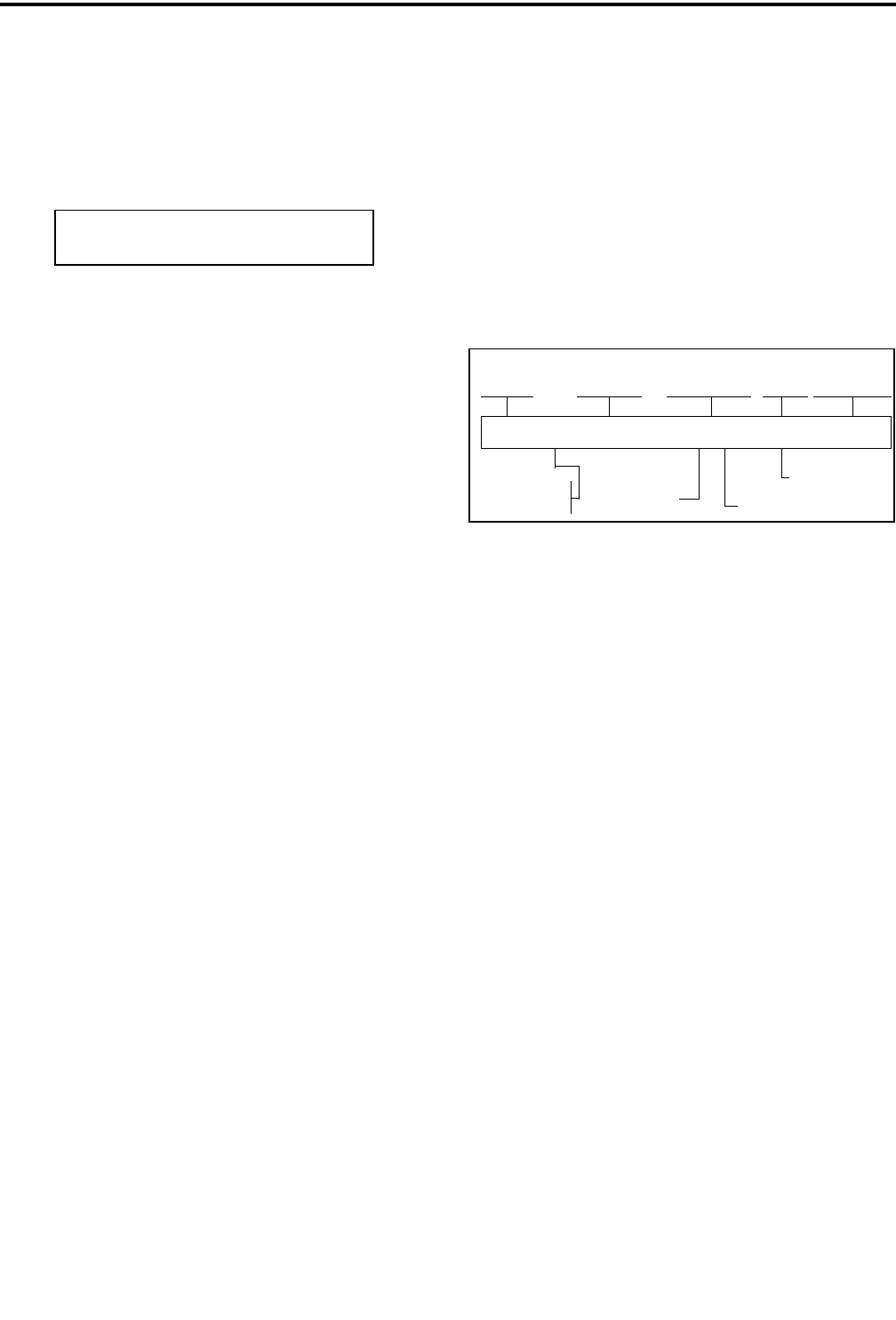
Figure 2-1 Front Panel Controls
Speaker
Display
DTMF Keypad
Option Keys
Microphone
Full Keypad Model Limited Keypad Model
Up/Down Sw
Option Keys
2.3.2 TOP PANEL CONTROLS
Two-Color Indicator - Indicates the following
conditions:
Steady Red - Transmitter keyed, normal power.
Flashing Red - Transmitter keyed, low battery (the
low power mode is automatically selected).
Steady Green - Carrier detected in receive mode.
Flashing Green - Low battery in receive mode. In
addition, when scanning, it flashes when the prior-
ity channel is scanned while receiving a message
on a non-priority channel.
Option Switch - This is a three-position toggle switch
that can be system operator programmed to control
some function (see Section 2.2).
On-Off/Volume - Turning the knob clockwise turns
power on and sets the volume level. Turning it coun-
terclockwise to the detent turns power off.
Figure 2-2 Top Panel Controls
Emergency
(Option)
On-Off
Volume
Channel
Switch
Antenna
Connector
Option
Sw Switch
OPERATION
2-4 September 2001
Part No. 001-5100-001
Channel Switch - This 16-position switch allows up
to 16 channels to be selected. This switch operates in
conjunction with up to 16 programmable zones to
allow up to 256 channels to be selected.
Antenna Connector - Connection point for the
antenna. Make sure that the antenna is tight before
using the radio.
Emergency Switch - If the radio is programmed for
emergency transmissions, pressing this switch alerts a
dispatcher, for example, of an emergency condition.
Refer to descriptions in Sections 2.6.11 and 2.7.10 for
more information.
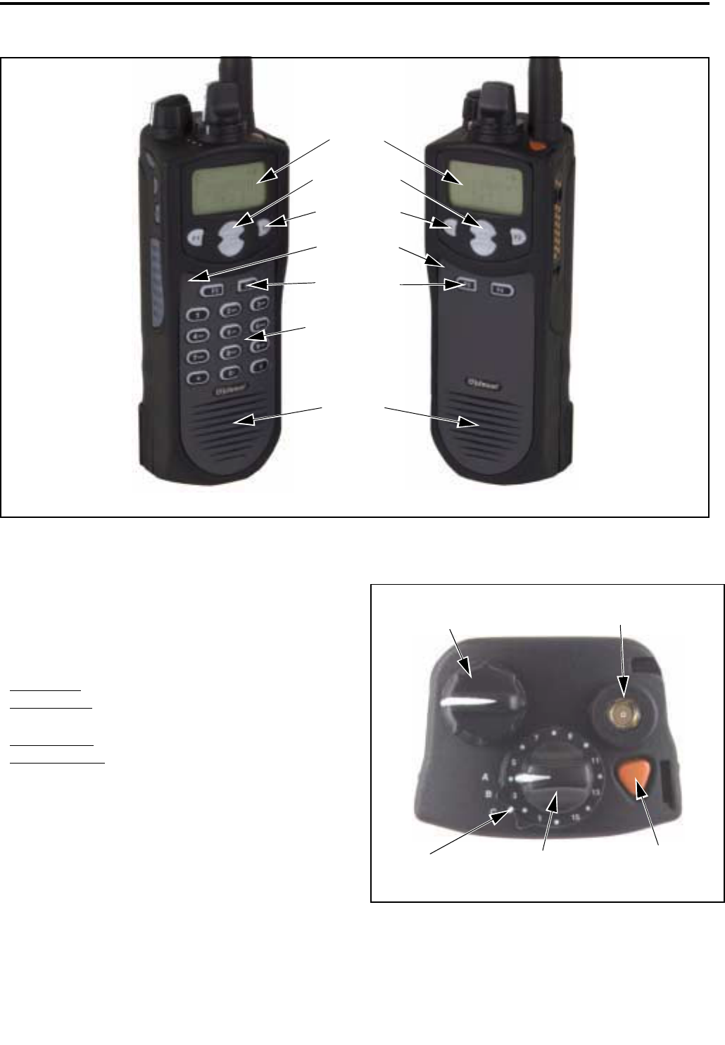
2.3.3 SIDE CONTROLS
Option Switches 1, 2, and 3 - These switches can be
system operator programmed to control a specific
function (see Section 2.2).
PTT Switch - This switch is pressed to turn the trans-
mitter on. The indicator on the top panel lights red
when the transmitter is keyed.
Battery - To remove the battery, press the release on
the bottom toward the front of the transceiver and slide
the battery outward.
Accessory Connector - Connection point for optional
accessories such as a speaker/microphone.
2.3.4 DISPLAY
The front panel display is shown above. In the
conventional mode, if the Display Information option
switch is programed, either the channel number,
channel name, or frequency can be selected (see
Section 2.6.2).
The following information is indicated in the
display:
Alphanumeric Characters - These eight characters
indicate the selected channel, error conditions, and
other information.
Sec - Indicates that transmissions are encrypted (see
Section 2.4.13).
Dig - Indicates that a digital (Project 25) conventional
channel is selected.
Rx - Indicates that a carrier is being detected on the
selected or scanned channel. This indication is
displayed in conjunction with a green LED on the top
panel (see Section 2.3.2).
Tx - Indicates the transmitter is keyed. This indication
is displayed in conjunction with a red LED on the top
panel.
Pgm - Indicates that the keypad programming mode is
selected (see Section 2.9).
SL - Indicates that the displayed channel is in the scan
list (see Section 2.5.7).
Pri - Indicates that the displayed channel is
programmed as the current group’s priority channel
(see Section 2.6.13).
Option Switches
PTT Switch
Battery Pack
Accessory
Connector
Sec Dig Rx Tx Pgm SL Pri Call ID Scan
Alphanumeric Display

OPERATION
2-5 September 2001
Part No. 001-5100-001
Call ID - Indicates that the display is showing the ID
of the calling party (see Section 2.7.4).
Scan - Indicates that system scan is activated (see
Section 2.5).
2.4 GENERAL OPERATION
2.4.1 INTRODUCTION
The following section describes features available
with both trunked and conventional operation.
Features unique to conventional channels are
described in Section 2.6, and features unique to
SMARTNET/SmartZone channels are described in
Section 2.7.
2.4.2 TURNING POWER ON AND SETTING
VOLUME
Power is turned on and off by the On-Off/Volume
switch on the top panel. When power is initially turned
on, an alert tone sounds and the indicator on the top
panel flashes green. If a SMARTNET/SmartZone
channel is selected, the zone alias is then displayed
followed by the unit ID (see Section 2.7.2). The
selected channel is then indicated.
To turn power off, turn the On-Off/Volume knob
counterclockwise until a click occurs. The display may
remain on for a few seconds after power is turned off.
It is recommended that power not be turned back on
again until the display is blank.
The relative volume level can be determined by
noting the position of the index on the On-Off/Volume
knob. To enable a reference tone for setting the
volume, proceed as follows:
•If key press tones are enabled (see Section 2.4.11), a
short tone sounds when front panel keys are pressed.
•If a conventional channel is selected and the
Monitor option switch is programmed (see Section
2.6.4), pressing that switch unsquelches/squelches
the receiver and either voice or background noise is
heard. If a SMARTNET/SmartZone channel is
selected, the receiver cannot be manually
unsquelched.
2.4.3 POWER-UP PASSWORD
General
The power-up password feature prevents unau-
thorized use of the transceiver. When it is enabled by
system operator programming, an eight-digit password
must be entered to make the transceiver operational
each time power is turned on. Passwords can be
entered even if the keypad is locked (see Section
2.4.6). The default password is eight zeros
(00000000). Refer to Section 3.7 for more informa-
tion on passwords.
If this feature is enabled, proceed as follows to
unlock the radio:
1. Turn radio power on and when “LOCKED” is dis-
played, enter the eight-digit numeric password
using the keypad. As each digit is entered, a dash is
displayed. If an incorrect digit is entered, press the
CLR key and re-enter the entire password.
2. When all eight digits have been entered, press the
ENT key. If the password is correct, the display
indicates normal zone and then channel informa-
tion. If an incorrect password is entered,
“LOCKED” is again displayed.
Changing Password
The current password can be changed as follows:
1. The locked mode must be selected to change the
password, so cycle power if necessary to display
“LOCKED”.
2. Enter the old eight-digit password and press the #
key (not ENT). If the correct password is entered,
“NEW PSWD” is displayed.
3. Enter the new password and press ENT. The pass-
word is changed.
2.4.4 BACKLIGHT
The backlight for the display and keypad can be
manually turned on by pressing the Backlight option
switch if it is available. The backlight can also be
system operator programmed to automatically turn on

OPERATION
2-6 September 2001
Part No. 001-5100-001
when any key is pressed. It then automatically turns
off after a programmed delay so that battery drain is
minimized.
2.4.5 OPTION SWITCHES
The programmable option switches are as
follows:
•F1, F2, F3, and F4 on front panel. In addition, with
full keypad (18-key) models, the # key is program-
mable (see Figure 2-1).
•The two push-button switches on the side panel (see
illustration in Section 2.3.3).
•The 3-position toggle switch on the top panel (see
Figure 2-2).
If your radio is programmed with both conven-
tional and SMARTNET/SmartZone channels (see
Section 2.4.12), these option switches can be system
operator programmed to control a different set of func-
tions for each channel type. For example, the F1
switch could select Hi/Lo Power when a conventional
channel is selected and Private Calls when a
SMARTNET/SmartZone channel is selected. The
available functions in each mode are indicated in the
tables in Section 2.2. If no option switch has been
programmed to control a particular function, that func-
tion may not be available or may be in a fixed mode.
2.4.6 KEYPAD LOCK
If the Keypad Lock option switch has been
programmed, the keypad can be locked (disabled) to
prevent keys from being accidentally pressed. To lock
the keypad, simply press this switch. Then to unlock it
again, press and hold it until a tone sounds. The
keypad can also be disabled by system operator
programming. It is then permanently disabled and
cannot be re-enabled by the user.
2.4.7 LOW BATTERY INDICATION
When the battery voltage falls below a preset
level, the radio can be programmed so that any or all
of the following indications occur:
•The indicator on the top panel flashes red in the
transmit mode and green in the receive mode.
•A chirp sounds every 5 seconds in the receive mode.
•A chirp sounds every 5 seconds in the transmit
mode.
The battery should be recharged as soon as prac-
tical after a low battery indication appears.
2.4.8 CHANNEL AND ZONE SELECTION
Channel Select
To change the current channel, rotate the 16-
position channel selector knob on the top panel to the
desired position. With SMARTNET/SmartZone chan-
nels, the selected channel is always indicated by an
alias (name). The alias is also displayed with conven-
tional channels if the Display Mode option switch is
not programmed. If this switch is programmed, the
channel number or frequency may also be displayed
(see Section 2.6.2).
Zone Select
A zone is a group of up to any 16 conventional
and SMARTNET/SmartZone channels defined by
system operator programming. Up to 16 zones can be
programmed for a total of 16 x 16 channels per zone or
256 channels. One use of zones may be to select
groups of channels programmed for operation in
different geographical areas or radio systems. If select-
able zones have been programmed in your radio,
consult your system operator for more information on
how they are used. Zones are selected as follows:
1. Press the Zone option switch and the alias (name) of
the current zone is flashed in the display.
2. Use the number keys to enter the desired zone
number or scroll through the available zones using
the and keys.
3. When the desired zone is displayed or entered,
select it by pressing the ENT key or waiting 4
seconds.

OPERATION
2-7 September 2001
Part No. 001-5100-001
2.4.9 HOME ZONE
The radio can be programmed with a home zone.
Then when power is turned on, the radio can be
programmed so that either the home or last selected
zone is automatically selected.
If the Home Zone option switch is programmed,
it can be used to quickly select or change the home
zone. To select the home zone, simply press this
switch. To change the home zone to the currently
selected zone, press and hold this switch until a tone
sounds (approximately 1 second).
2.4.10 TIME-OUT TIMER
The time-out timer disables the transmitter if it is
keyed for longer than the programmed time. It can be
programmed on each channel for times of 15 - 225
seconds or it can be disabled (not used). If the trans-
mitter is keyed continuously for longer than the
programmed time, the transmitter is disabled and an
invalid condition tone sounds. Five seconds before
time-out occurs, an alert tone sounds to indicate that
time-out is approaching. The timer and tone are reset
by releasing the PTT switch.
One use of this feature is to prevent a channel
from being kept busy for an extended period by an
accidentally keyed transmitter. It can also prevent
possible transmitter damage caused by transmitting for
an excessively long period. Conventional channels can
also be programmed with the Penalty and Conversa-
tion timers that are described in Sections 2.6.7 and
2.6.8.
2.4.11 TONE ENABLE/DISABLE
The supervisory tones (see Section 2.8) can be
enabled and disabled by the Tones On-Off option
switch if it is programmed. When tones are enabled by
this switch, “TONE ON” is momentarily displayed
and a tone sounds. Conversely, when tones are
disabled, “TONE OFF” is displayed and no tone
sounds. If the Tones On-Off option switch is not
programmed, tones are fixed in the on or off mode by
programming.
2.4.12 TRANSCEIVER OPERATING MODES
Introduction
Each selectable channel can be programmed for
either the conventional or SMARTNET/SmartZone
operating mode. For example, Zone 1/Channel 1 could
be a conventional channel, Zone 1/Channel 2 a
SMARTNET channel, and so on. More information on
these modes follows.
Conventional Mode
This is a non-trunked operating mode which
accesses independent radio channels (there is no auto-
matic access to several channels). Monitoring before
transmitting may not be automatic in this mode, so you
may need to manually monitor the channel before
transmitting to make sure that it is not in use. Either
analog or digital (Project 25) signaling may be used.
When a digital channel is selected, “DIG” is indicated
in the upper part of the display. Channel monitoring
and other operating features unique to conventional
channels are described starting with Section 2.6.1.
SMARTNET™/SmartZone® Mode
This is a trunked operating mode that uses ID
codes to select what mobiles are being called and what
calls are received. Monitoring is performed automati-
cally and special messages and tones indicate busy and
out-of-range conditions. Enhanced features include
roaming (SmartZone only), telephone, private, and
emergency calls, Call Alert™, and messaging. Either
analog or digital signaling may be used. When a
digital channel is selected, “Dig” is indicated in the
upper part of the display. Operating features unique to
SMARTNET/SmartZone channels are described
starting with Section 2.7.1.
When a SMARTNET or SmartZone channel is
selected or the radio is powered up on one of those
channels, it searches for a control channel and
attempts to register on the radio system. Once a
control channel is found, the alias (name) of the
selected channel is displayed. If a control channel
could not be found (because of an out of range condi-
tion or the system ID is not correct, for example), “NO
SYS” is displayed and the radio continues to search
for a control channel.

OPERATION
2-8 September 2001
Part No. 001-5100-001
The control channel transmits and receives
system information to and from all radios registered on
the system. Therefore, once a control channel is found,
it is continuously monitored for incoming call infor-
mation and is used to make call requests. The radio
automatically changes to a traffic channel to place and
receive calls and then returns to the control channel
when the call is complete.
2.4.13 SECURE COMMUNICATION
This transceiver may be optionally equipped to
provide secure communication on some or all chan-
nels. This feature encrypts your voice so that it can be
understood only by someone using a transceiver
equipped with a similar encryption device and encryp-
tion codes.
When a secure call is received or transmitted,
“Sec” is indicated in the upper part of the display.
Secure communication can be programmed on a per
channel basis to operate in various ways. If equipped
with the Clear/Secure option switch and the current
channel is programmed to allow switch selection,
secure communication can be manually enabled and
disabled by that switch. Secure communication can be
programmed on a per channel basis to operate in
various ways. Refer to Sections 2.6.17 and 2.7.15 for
more information.
2.5 SCANNING
2.5.1 INTRODUCTION
Scanning cycles through a list of channels called
a “scan list”, checking each for messages. When a
message is detected that your transceiver is
programmed to receive, scanning stops and the
message is received. Shortly after the message is
complete, scanning resumes (unless it has been
disabled).
There are two basic scan modes: Standard and
Radio Wide. The Standard mode is unique to the type
of channel selected (conventional or SMARTNET/
SmartZone), and the Radio Wide mode is the same
regardless of the channel type selected. Only one of
these scan modes can be enabled at a time. Therefore,
if standard scanning is enabled while radio wide scan-
ning is occurring, radio wide scanning is automatically
disabled and vice versa. More information on these
modes follows.
2.5.2 STANDARD SCANNING
Standard scanning monitors only channels that
are the same type as that currently selected. There-
fore, if a conventional channel is selected, only
conventional channels are scanned, and if a
SMARTNET channel is selected, only SMARTNET
channels are scanned. Standard scanning is turned on
and off by the Scan option switch as follows. If this
switch is not programmed, standard scanning is not
available.
•To turn standard scanning on, press the Scan option
switch. Scanning is enabled when the “Scan” icon
is indicated in the upper right corner of the front
panel display and “SCAN ON” is briefly displayed.
•To turn scanning off, press the Scan option switch
again. The “Scan” icon is then no longer indicated
and “SCAN OFF” is briefly displayed.
•If the zone or channel is changed while scanning is
selected, scanning continues on the same or a
different scan list (see scan list information which
follows).
2.5.3 RADIO WIDE SCANNING
Radio wide scanning monitors the channels in the
preprogrammed radio wide scan list (see Section
2.5.5). This list may contain up to 16 channels of any
type (conventional or SMARTNET/SmartZone)
assigned to any zone. Radio wide scanning is turned
on and off by the Radio Wide Scan option switch as
follows. If this switch is not programmed, radio wide
scanning is not available.
•To turn radio wide scanning on, press the Radio
Wide Scan option switch. Scanning is enabled when
“Scan” is indicated in the upper right corner of the
front panel display and “SCAN ON” is briefly
displayed.
•To turn radio wide scanning off, press the Radio
Wide Scan option switch again. The “Scan” icon is
then no longer indicated and “SCAN OFF” is briefly
displayed.

OPERATION
2-9 September 2001
Part No. 001-5100-001
•If the zone or channel is changed while radio wide
scanning, scanning continues normally.
2.5.4 SCAN RESUME DELAY
When a message is received or transmitted while
scanning, there is a system operator programmable
delay before scanning resumes. The delay after
receiving a call prevents another message from being
received before you can make a response, and the
delay after transmitting a call ensures that you hear a
response to your call instead of another message
occurring on some other channel.
2.5.5 STANDARD MODE SCAN LIST
NOTE: The selected channel is always scanned.
With conventional operation, up to three scan lists
can be programmed. The list that is scanned is selected
by the Scan option switch as described in Section
2.6.12. Selecting another conventional channel does
not change the current scan list. The scan lists are user
programmable if the Scan Edit option switch is
programmed (see Section 2.5.9).
With SMARTNET/SmartZone operation, each
channel can be programmed so that one of up to three
different scan lists is automatically selected or scan-
ning is disabled. The scan list assigned to the current
channel is not user selectable, but it is user program-
mable if the Scan Edit option switch is programmed
(see Section 2.5.9).
2.5.6 RADIO WIDE MODE SCAN LIST
With radio wide scanning, there is only one
preprogrammed scan list available regardless of the
type of channel selected, and it is not user
programmable.
2.5.7 DETERMINING WHICH CHANNELS ARE
IN SCAN LIST
Channels in the standard SMARTNET/Smart-
Zone and radio wide lists are not indicated. With
conventional channels, the selected channel is in the
current scan list if “SL” (Scan List) is indicated in the
upper part of the display.
2.5.8 NUISANCE CHANNEL DELETE
With standard scanning, channels can be tempo-
rarily deleted from the scan list, for example, if
messages on a channel become annoying. This feature
is not available with radio wide scanning. Proceed as
follows:
NOTE: The selected channel and conventional priority
channels cannot be deleted from the scan list.
1. While receiving a message on the channel to be
deleted, press and hold the Scan option switch until
the alert tone sounds (about 1 second).
2. The channel is then deleted and scanning of the
remaining channels in the scan list resumes.
3. Deleted channels are added back into the scan list if
any of the
following events occur:
•Scanning is turned off and then on again using the
Scan switch.
•Transceiver power is turned off and then on again.
•The scan list is reselected by pressing the number
key corresponding to the list number (conven-
tional) or by selecting another channel
(SMARTNET/SmartZone).
•Another channel is selected by the top panel
channel switch.
2.5.9 PROGRAMMING A SCAN LIST
When full keypad (18-key) models, conventional
and SMARTNET/SmartZone standard scan lists are
user programmable if the Scan Edit option switch is
programmed and user programming of the list is
allowed. Scan list programming is not available with
limited keypad (6-key) models. Proceed as follows to
program a scan list:
Preliminary
1. With conventional channels, select the list to be
edited (1-3) by pressing the key corresponding to
the desired list number with scanning enabled (see
Section 2.6.12). If a list is not selected, the last
active scan list is automatically edited. With
SMARTNET/SmartZone channels, the scan list for

OPERATION
2-10 September 2001
Part No. 001-5100-001
the selected channel is fixed and cannot be changed.
Scanning may also be disabled on some channels.
2. If scanning is enabled, turn it off by pressing the
Scan option switch.
3. Press the Scan Edit option switch. The alias of the
first channel in the scan list is displayed. If scan list
programming or scanning is disabled on the selected
list or channel, “NO LIST” is momentarily
displayed and scan list programming is not avail-
able. Proceed as follows to delete or add a channel:
To Delete a Channel:
4. Select the channel you want to delete by pressing the
and keys.
5. With conventional channels, to delete the displayed
channel and exit this mode, press the CLR (F3) key.
With SMARTNET/SmartZone channels, press the
“2” key and then ENT (F4).
NOTE: The priority channel cannot be deleted (see
Section 2.6.13).
To Add a Channel:
1. Press the Scan Edit option switch. The alias of the
first channel in the scan list is displayed.
2. Enter the two-digit zone and channel number of the
channel you want to add. For example, to add Zone
1/Channel 5, enter “0105”. Refer to Section 2.4.8
for more information on zones and channels.
3. With conventional channels, to add the channel to
the scan list and exit this mode, press the ENT (F4).
With SMARTNET/SmartZone channels, press the
“1” key and then ENT (F4).
2.6 CONVENTIONAL FEATURES
2.6.1 INTRODUCTION
The following information describes features
unique to the conventional operating mode (see brief
description in Section 2.4.12). Refer to Section 2.4 for
information on features common to all operating
modes, and to Section 2.7 for information on features
unique to the SMARTNET/SmartZone mode.
2.6.2 DISPLAY MODE SELECTION
If the Displayed Information option switch is
programmed, it is usually the three-position toggle
switch on the top panel. This switch selects the
following conventional channel display modes. If this
switch is not programmed or a SMARTNET/Smart-
Zone channel is selected, the Alias mode is always
used.
Alias - The preprogrammed alphanumeric tag for the
channel is displayed.
Number - The channel number from 1-16 is displayed
as “CHAN xx”.
Frequency - The frequency of the selected channel is
displayed in megahertz. The transmit frequency is
displayed in the transmit mode and the receive
frequency is displayed in the receive mode.
NOTE: The channel number can also be determined
by noting the number (1-16) indicated by the index on
the channel selector knob.
2.6.3 MONITORING BEFORE TRANSMITTING
With conventional operation, you may need to
manually monitor the channel before transmitting to
make sure that it is not being used by someone else. If
you were to transmit while someone else was using the
channel, you would probably disrupt their conversa-
tion. Channels are monitored automatically or manu-
ally as follows:
Automatic Channel Monitoring
If the selected channel is programmed for Busy
Channel Lockout feature (consult your system oper-
ator), monitoring is performed automatically. Refer to
the description of this feature in Section 2.6.5 for more
information.
Manual Channel Monitoring
The automatic monitoring just described may not
be programmed or it may occasionally disable the

OPERATION
2-11 September 2001
Part No. 001-5100-001
transmitter even if the channel is not in use. In this
case, the channel must be monitored manually as
follows:
Rx Indicator - With scanning disabled, note if the indi-
cator on the top panel is steady green. If it is not, the
channel is not being used and you can transmit your
call. If it is green, the channel may be busy and you
should not place your call (see next paragraph).
Monitor Mode - There may be times when the busy
indication is displayed even though no one is using the
channel. Monitoring should then be performed by
disabling Call Guard squelch using the Normal/Selec-
tive option switch as described in Section 2.6.6 or the
monitor mode described next.
2.6.4 MONITOR MODE
The monitor mode temporarily disables squelch
control features (such as Call Guard® squelch) so that
all messages are heard on the selected channel. It also
overrides the Busy Channel Lockout feature (see next
section) and temporarily halts scanning.
To monitor the selected channel, select the
monitor mode by briefly pressing or pressing and
holding the Monitor option switch (if available). The
receiver unsquelches and a rushing noise or voice is
heard when the monitor mode is enabled. To disable
the monitor mode and return to normal operation,
release the Monitor switch or press it a second time.
If scanning is enabled, pressing and holding the
Monitor option switch monitors the current scanned
channel instead of the selected channel if applicable.
2.6.5 BUSY CHANNEL LOCKOUT
The Busy Channel Lockout feature (also called
Transmit Disable On Busy) automatically disables the
transmitter if the channel is busy when the PTT switch
is pressed. When a busy condition is detected by this
feature, the transmitter is disabled, “BUSY” is indi-
cated in the display, and a tone similar to a standard
telephone busy tone sounds until the PTT switch is
released. The transceiver can be programmed to
operate in one of the following modes on each
channel:
Off - Busy channel lockout is disabled and the trans-
mitter keys even if the channel is busy.
Noise - The transmitter is disabled if a carrier is
detected on the channel.
Tone - The transmitter is disabled if an incorrect Call
Guard (CTCSS/DCS) or NAC code is detected (see
Section 2.6.6). An incorrect code is any code other
than the one programmed for the current channel.
If busy override is permitted by programming, it
is possible to transmit even when the transmitter is
disabled by this feature. Simply release the PTT switch
and then quickly press it again.
2.6.6 CALL GUARD SQUELCH
Introduction
Tone or digital Call Guard squelch (also called
CTCSS/DCS signaling) can be programmed on each
conventional analog transmit and receive channel in
any order desired. The reverse burst and turn-off code
are always transmitted and also detected on channels
programmed with Call Guard squelch.
The Call Guard squelch feature eliminates
distracting messages intended for others using the
channel. This is done by using a subaudible tone or
digital code to control the squelch. This tone or code is
unique to a user or a group on that channel. This tone
or code is transmitted with the voice signal but is not
heard because it is in the subaudible range and is atten-
uated by a filter. Call Guard squelch must be used in
both the transmitting and receiving transceiver to be
functional.
Call Guard Squelch Enable/Disable
To disable Call Guard (Selective) squelch so that
all messages on the selected or scanned channels are
heard, press the Normal/Selective option switch (if
available) so that “NORMAL is flashed in the display.
Then to re-enable Call Guard squelch, press the
Normal/Selective switch again so that “SELECTIV” is
flashed. The mode selected by this switch does not
change when other channels are selected or power is
cycled. Call Guard squelch can also be disabled by the
monitor mode described in Section 2.6.4.

OPERATION
2-12 September 2001
Part No. 001-5100-001
Tone Call Guard Squelch
Tone-type Call Guard squelch utilizes subaudible
CTCSS tones from 67-254.1 Hz. Although there are
42 tones assigned, those above 33 (210.7 Hz) are
normally not used because of their close proximity to
the voice band which starts at 300 Hz. In addition,
tones 11 (97.4 Hz), 39 (69.3 Hz), 40 (206.5 Hz), 41
229.1 Hz), and 42 (254.1 Hz) are normally not used
because they may cause interference with adjacent
tones.
A reverse burst is transmitted when the push-to-
talk switch is released and also detected when calls are
received. It is a 180-degree phase reversal for a period
of time determined by the tone frequency, and it elimi-
nates the squelch tail (noise burst) in the receiving
transceiver. Both the transmitting and receiving trans-
ceiver must be equipped with this feature for it to be
utilized.
Digital Call Guard Squelch
Digital Call Guard squelch (CDCSS) uses digital
data instead of subaudible tones to control the squelch.
This data consists of continuous repetitions of 23-bit
words. No bit or word synchronization information is
used. When the push-to-talk switch is released, a turn-
off code is transmitted which eliminates the squelch
tail similar to the reverse burst.
Although there are thousands of possible code
combinations with 23 bits, only 83 are unique with the
data scheme used. The number specified when the
code is programmed is actually a seed for a special
algorithm used to generate the 23-bit data word. The
data is transmitted at a rate of 134.4 bits per second.
Therefore, approximately six words are transmitted
each second. When the data is decoded, 23-bit samples
are taken and then the bits are rotated to determine if a
valid code was received.
Keypad Selectable Call Guard Code (CTCSS/DCS)
If you have the full keypad (18-key) model and
the ability to change Call Guard codes has been
enabled by programming, the transmit and receive
codes from one channel can be temporarily or perma-
nently reassigned to all channels of the current zone.
Proceed as follows:
1. Using the number keys, enter the number of the
channel that is programmed with the code you want
to reassign to all channels (only channels 1-9 can be
selected). See Section 2.6.2 for information on
displaying channel numbers.
2. The display then briefly indicates “CODE x”, where
“x” is the key you pressed. The codes assigned to
that channel are then reassigned to all the other
channels in the current zone. The reassignments
remain in effect even after power is cycled.
3. To restore all Call Guard codes in the current zone
to the original settings, press the “0” key.
NOTE: Keypad programming described in Section 2.9
can be used to change the Call Guard code of indi-
vidual channels.
2.6.7 PENALTY TIMER
A penalty timer may be programmed on conven-
tional channels to prevent transmissions for 15 - 225
seconds after the time-out timer described in Section
2.4.10 disables the transmitter. The penalty timer starts
when the PTT switch is released after the transmitter
has been disabled. If the PTT switch is pressed during
the penalty time, the time-out indication occurs again.
A beep sounds when the penalty timer expires and the
transmitter can then be keyed.
2.6.8 CONVERSATION TIMER
A conversation timer can be programmed on
conventional channels to limit the total length of a
conversation rather than just the length of each trans-
mission as with the time-out timer. This timer can be
programmed for 0.5 - 7.5 minutes, and it is reset when
the time between transmissions exceeds the penalty
time just described. A warning tone sounds 5 seconds
before the conversation timer expires. When it expires,
the transmitter is disabled and a warning tone sounds.
The transmitter remains disabled for the length of the
penalty time, and a beep sounds when it can be keyed
again.
2.6.9 REPEATER TALK-AROUND
Normally, all your transmissions go through a
repeater which usually increases range. However, if

OPERATION
2-13 September 2001
Part No. 001-5100-001
you are out of range of the repeater, you cannot talk to
anyone else on that channel even though the mobile
you are calling may be only a short distance away. To
allow communication when this situation occurs,
repeater talk-around can be used to allow direct
communication with a mobile without going through a
repeater.
Repeater talk-around can be selected if the
Repeater Talk-Around option switch (if available).
When talk-around is enabled by this switch, “RTA
ON” is flashed in the display. Then when it is disabled
by pressing the switch again, “RTA OFF” is flashed.
Changing channels or turning power off does not
change the selected talk-around mode.
2.6.10 POWER OUTPUT SELECT
If the High/Low Power option switch is
programmed and power selection is permitted on the
current channel, either high or low transmitter power
can be selected. Generally, the high power setting
allows you to transmit longer distances but uses more
battery power, and the opposite occurs with the low
power setting.
Pressing the High/Low Power switch toggles the
power setting. The new level is flashed in the display
when this switch is pressed as “HI POWER” or “LO
POWER”. If power selection is not permitted on the
channel, the fixed power level is flashed and no power
change occurs. Turning power off or changing chan-
nels does not change the power setting selected for a
channel. Selectable power is not available with 800
MHz models.
2.6.11 EMERGENCY MODE (CONVENTIONAL)
On conventional channels, an emergency mode
may be programmed to be selectable by the Emer-
gency switch located next to the antenna (see illustra-
tion in Section 2.3.2). Scanning is automatically
disabled in the emergency mode, so transmissions
occur on the selected channel.
If an analog channel is selected and scrambling is
programmed, pressing the Emergency switch sends an
emergency signal on the selected channel 20 times or
until an acknowledgment is received. Keying the radio
also cancels the emergency condition.
If a Project 25 (digital) channel is selected,
pressing this switch selects the emergency mode and if
the PTT switch is pressed, an emergency status is sent.
Radio power must be turned off to cancel the emer-
gency mode on a Project 25 channel.
2.6.12 CONVENTIONAL MODE SCANNING
General
The following information describes scanning
features unique to conventional operation. Scan opera-
tion common to all modes is described in Section 2.5,
and scan operation unique to SMARTNET/
SmartZone operation is described in Section 2.7.12.
Selecting a Scan List
With full keypad (18-key) models, one of up to
three scan lists can be selected when scanning with a
conventional channel selected. These lists can be
system operator or user programmed as described in
the information which follows. With limited keypad
(6-key) models, only one scan list is available and it
cannot be user programmed. However, nuisance chan-
nels can still be temporarily deleted as described on
Section 2.5.8.
Proceed as follows to select a scan list with full
keypad models:
1. If required, enable scanning by pressing the Scan
option switch.
2. To select a list, press the number key corresponding
to the number of the desired list (1-3). The selected
list is then briefly displayed as “Scan x” where “x”
is the list number. The selected scan list is stored in
memory and does not change until this procedure is
repeated.
Transmitting in Scan Mode
Each conventional scan list can be programmed
for one of the following modes. These modes deter-
mine if priority sampling occurs and also the channel
on which transmissions occur while scanning. Refer to
the next section for more information.

OPERATION
2-14 September 2001
Part No. 001-5100-001
No Priority - No priority channel sampling occurs
when the list is selected. The radio transmits on the
selected channel.
Priority/Tx Priority - Priority sampling occurs and
the priority channel is the one programmed in the
selected scan list. The radio transmits on the priority
channel.
Priority/Tx Selected - Priority sampling occurs and
the priority channel is the one programmed in the
selected scan list. The radio transmits on the selected
channel.
Priority on Selected - The priority channel is always
the selected channel. The radio transmits on the
selected channel.
Talk ba c k - No priority sampling occurs. The radio
transmits on the channel of a call while scanning is
halted. Then once scanning resumes, it transmits on
the selected channel.
2.6.13 PRIORITY CHANNEL SAMPLING
General
The priority channel sampling feature ensures
that when standard scanning is occurring, messages on
the priority channel are not missed while listening to a
message on some other channel. Your transceiver can
be programmed so that the priority channel is a fixed
channel associated with the current scan list, the
currently selected channel, or not used. When the
selected channel is a priority channel, “Pri” is indi-
cated in the upper part of the display.
Priority channel sampling occurs only with Stan-
dard conventional scanning. It does not occur with
Radio Wide scanning, when listening to any type of
SMARTNET/SmartZone call, or when transmitting. A
series of “ticks” may be heard and the indicator on the
top panel flashes green when the priority channel is
sampled while listening to a message on some other
channel.
The priority sampling times are programmed by
the following parameters:
Lookback Time A - This time determines how often
the priority channel is checked for activity. Times of
0.25-4.00 seconds in 0.25-second steps can be
programmed.
Lookback Time B - This time determines how often
the priority channel is checked once an incorrect Call
Guard (CTCSS/DCS) or NAC code is detected. Since
it takes much longer to detect an incorrect Call Guard
signal than a carrier, this time should be relatively long
to prevent the interruptions from making a message
difficult to understand. Times of 0.5-8.0 seconds can
be programmed in 0.5-second steps.
Changing The Priority Channel
If a specific priority channel is associated with
the current scan list, it can be changed if the Priority
option switch is programmed. Proceed as follows:
1. Select the scan list number to be edited as described
in Section 2.6.12. If a list is not selected, the last
active scan list is automatically edited.
1. Make sure that both radio-wide and standard scan-
ning are off (“Scan” is not indicated in display).
2. Select the channel that you want to be the priority
channel using the channel selector switch on the top
panel. If the channel is in a different zone, also select
the appropriate zone.
3. Press the Priority option switch and the “Pri” is
displayed to indicate that the selected channel is
now the priority channel.
2.6.14 PLACING AND RECEIVING STANDARD
CONVENTIONAL CALLS
Standard conventional calls are calls to or from
other mobile units on the selected channel. The proper
coded Call Guard signaling (see Section 2.6.6) may
need to be transmitted for them to receive your call
and also for you to receive their calls. Proceed as
follows to place and receive these calls:
Placing a Standard Conventional Call
1. Turn power on and set the volume as described in
Section 2.4.2. Select the channel programmed for
the mobile you want to call (see Section 2.4.8).

OPERATION
2-15 September 2001
Part No. 001-5100-001
2. Monitor the channel automatically or manually as
described in Section 2.6.3.
3. Press the PTT switch and the call proceeds as
follows:
•If the Busy Channel Lockout feature is programmed
on the channel, the transmitter is automatically
disabled if the channel is busy (see Section 2.6.5).
•Otherwise, busy and out-of-range conditions are not
indicated and speaking can begin after monitoring
the channel as described in Section 2.6.3.
4. Press (and hold) the PTT switch to talk and release
it to listen.
Receiving a Standard Conventional Call
1. Select or scan the channel programmed for the call
you want to receive (refer to Sections 2.5 and 2.6.12
for more scanning information).
2. When the call is received, press the PTT switch to
talk and release it to listen. If scanning, you may
have to respond before scanning resumes to ensure
that the response occurs on the channel of the call.
2.6.15 DTMF/ANI SIGNALING
DTMF (Dual Tone Multi-Frequency) tones can
be generated manually or automatically for ANI
(Automatic Number Identification) and other
purposes. The following options may be enabled by
system operator programming for each conventional
channel:
DTMF Keypad - Pressing 0-9, *, or # on the keypad
while holding the PTT switch transmits the corre-
sponding tone until the key is released.
Pre-Tx ANI - A preprogrammed ANI sequence is
automatically sent when you press the PTT switch.
Post-TX ANI - A preprogrammed ANI sequence is
automatically sent each time you release the PTT
switch.
Disabled - All DTMF signaling is disabled.
2.6.16 PROJECT 25 MODE FEATURES
Individual, Group, and NAC Codes
Individual ID - Each transceiver that operates on
Project 25 (digital) channels is programmed with
an 8-digit individual ID. This ID is unique for
each transceiver and can be any number from
1-16777216. When power is turned on with a
Project 25 channel selected, this ID is briefly
displayed.
Group ID - Each Project 25 channel is programmed
with a group ID that determines which group of
mobiles will receive the call. A call is received if
any Project 25 channel is programmed with that
group and the correct NAC is detected (see
following description). Group IDs can be any
number from 0-4095.
NAC - Project 25 conventional channels use a NAC
(Network Access Code) instead of Call Guard
squelch coding (see Section 2.6.6) to control
which calls are received on a channel. The NAC
can be 0-4095, and each transmit and receive
channel can be programmed for a different code.
Other operation, such as monitoring before trans-
mitting, is similar to that of standard analog
channels.
To receive a Project 25 group call, the talk group
programmed with the group ID being transmitted must
be selected or scanned. In addition, the receive NAC
programmed for that channel must be detected.
Viewing Individual ID
Each transceiver which operates on Project 25
(digital) channels is assigned an eight-digit individual
ID. When power is turned on with a Project 25 channel
selected, the individual ID of your radio is briefly
displayed.
Changing Talk Group Assigned To A Channel
If the Talk Group Select option switch is
programmed and user talk group programming is
permitted on the channel, the talk group assigned to a
channel can be changed. This change is permanent

OPERATION
2-16 September 2001
Part No. 001-5100-001
(cycling power does not reselect the old talk group).
Proceed as follows:
1. Select the channel to be changed and then press the
Talk Group Select option switch.
2. Display the talk group to be assigned to that channel
by pressing the and keys. Talk groups are
indicated by an alias (unique alphanumeric identifi-
cation).
3. To select that talk group and return to normal oper-
ation, press the Talk Group select switch again. If
talk group selection has been disabled on the chan-
nel by programming, the talk group does not change
and an error tone sounds.
Individual Calls
If the Individual Call option switch is
programmed and the radio is a full keypad (18-key)
mode, individual calls can be placed to a specific
mobile radio on Project 25 channels. This call differs
from standard group calls in that only one mobile
instead of entire groups of mobiles may receive the
call. To respond to an individual call, simply press the
PTT switch and begin talking before a call timer
expires. Proceed as follows to place this call:
1. Press the Individual Call option switch and the iden-
tification of the last individual call placed is dis-
played as IDxxxxxx.
2. If required, enter the ID of the mobile being called
using the keypad.
3. Press the PTT switch and begin talking.
When individual calls are received, the trans-
ceiver may be programmed to display the selected talk
group, the talk group of the call, or the ID of the
calling radio.
2.6.17 CONVENTIONAL SECURE
COMMUNICATION
Introduction
There are two different protocols that can be used
to provide secure communication on conventional
analog channels: SecureNet™ and 460 scrambling.
More information on these protocols follows.
SecureNet
SecureNet is a proprietary Motorola protocol that
digitizes the voice and then encrypts it using the DES
algorithm. It provides the highest level of security.
There are two DES protocols:
•DES (CFB) uses cipher feedback DES encryption.
A disadvantage of this type is reduced communica-
tion range when compared to clear voice.
•DES-XL uses counter addressing feedback DES. It
provides better range but at lower voice quality.
The transmission mode (DES or DES-XL) is
selected by the programming software for each
SecureNet analog channel. If a channel is programmed
for DES-XL, it will also receive DES, but transmis-
sions always occur in DES-XL.
Each SecureNet capable channel is assigned an
encryption number from 0-15. The key corresponding
to this number is loaded into the radio using the
Motorola key loader. There is a maximum of 16 keys
that can be loaded into the radio at one time.
Transmissions on an analog channel are in the
clear mode if the channel has been strapped to the
clear mode by programming, and in the SecureNet
mode if it has been strapped to SecureNet. If the
channel has been strapped to “switched”, the mode is
selected by the Clear/Secure option switch. When a
message is received or transmitted in the secure mode,
“Sec” is indicated in the upper part of the display.
If an attempt is made to transmit a secure
message without loading the corresponding key,
“KEYFAIL” is displayed. The message must then be
transmitted in the clear mode (this is possible only if
the channel is strapped to “switchable”) or the key
must be loaded.
460 Scrambling
The 460 Scrambling protocol is a proprietary
Transcrypt protocol that is compatible with the stand-
alone scrambling option from Transcrypt. If equipped

OPERATION
2-17 September 2001
Part No. 001-5100-001
with the 460 Scrambler, a Clear/Secure option switch
may be programmed. Pressing this switch changes the
transmission mode for the selected channel and
momentarily displays either “CLEAR” or “SECURE”.
In the coded mode, transmissions are in scram-
bled voice on any 460-enabled channel and the mobile
receiving the call automatically responds in the scram-
bled mode because the receiver automatically switches
between the clear and coded modes.
Although 16 generic codes are loaded, only one is
active and all 460-enabled channels use this code. The
460 scrambling option also provides several other
signaling enhancements including Digital ID, Auto-
matic Status and Location Update, Individual and
Group ID calling, and Emergency.
Transmit Mode Options
Either the SecureNet or 460 protocol can be
selected, and then the following transmit options are
available for each:
Clear - All calls are in the clear mode unless
responding to a secure call. If the response is then
made within the delay time (see Section 2.5.4), it
occurs in the secure mode.
Coded - All calls are made in the selected secure
mode.
Switched - The mode is selected by the Clear/Secure
switch. With 460 scrambling, if responding to a secure
call, the secure mode is automatically selected if the
response occurs within the delay time. When the clear
mode is selected by this switch, “CLEAR” is flashed,
and when the secure mode is selected, “SECURE” is
flashed.
Receive Mode Options
With 460 scrambling, clear and scrambled signals
are always autodetected. In addition, the user can
switch between the clear and secure mode at any time
using the Clear/Secure option switch. SecureNet
signals are unintelligible when 460 scrambling is used
and vice versa.
With the SecureNet protocol, the following
receive options can be programmed:
No Autodetect - Only signals coded like the transmit
signals are received.
Secure Autodetect - Both clear and SecureNet signals
are automatically detected. This mode is automati-
cally selected if the transmit mode is switch selectable.
Proper Key Autodetect - An incoming Securenet call
is compared against all of the available keys
programmed into the radio. If a match is found, the
call is decrypted using matched key.
Project 25 (Digital) Channels
Project 25 digital channels use the DES-OFB
protocol. Using this protocol on digital channels does
not result in the degraded range that occurs with
analog channels. The same transmit mode options are
available as with the preceding analog operation. In
the receive mode, clear and secure messages are
always automatically detected.
2.7 SMARTNET/SMARTZONE FEATURES
2.7.1 INTRODUCTION
The following information describes features
unique to the SMARTNET and SmartZone operating
mode (see brief description in Section ). Refer to
Section 2.4 for information on features common to all
operating modes, and to Section 2.4.12 for information
on conventional mode features.
2.7.2 VIEWING UNIT ID
Each radio in a SMARTNET system is identified
with a six-digit system ID and Unit ID. To display
these IDs, make sure that a SMARTNET channel is
selected and then turn power off and then on again.
The system ID is briefly displayed as SYxxxxxx
followed by the Unit ID as EDxxxxxx.
2.7.3 STANDARD GROUP CALLS
Standard group calls are between you and another
mobile, group of mobiles, or a control station (a radio

OPERATION
2-18 September 2001
Part No. 001-5100-001
at a fixed location). Most calls you make will probably
be this type.
Placing a Standard Group Call
1. Turn power on and set the volume as described in
Section 2.4.2. Select the channel programmed for
the talk group you want to call (see Section 2.4.8).
A regular or announcement talk group can be
selected.
2. If encryption is used, it may be automatically
selected. If not, select the secure mode if desired by
pressing the Clear/Secure option switch. Refer to
Section 2.4.13 for more information.
3. Press the PTT switch and when the alert tone
sounds, begin talking. Other indications that may
occur are as follows:
•If in the secure mode and your transceiver does not
have the proper encryption key, “KEYFAIL” is
displayed and the call must be made in the clear
mode (selected by the Clear/Secure option switch
if enabled on the channel).
•If the busy tone sounds and “BUSY” is displayed,
the system is busy. Release the PTT switch and
wait for the call back tone to sound. Then press the
PTT switch within 3 seconds and begin talking.
•If a continuous tone sounds while pressing the
PTT switch and “NO SYS” is displayed, you may
be out-of-range. Drive closer or away from
shielding objects and try again.
•If your unit ID is invalid, the call is being made to
an invalid group ID, or group calls are not allowed,
“REJECT” is displayed and an alert tone sounds.
•If an attempt is made to select the secure mode and
there is no available secure channel, “NO SEC” is
flashed and the call continues in the clear mode.
•If an attempt is made to change from the secure to
the clear mode and this is not permitted, “SEC
ONLY” is displayed and the call continues in the
secure mode.
Receiving a Standard Call
When a SMARTNET/SmartZone group call is
received, the transceiver can be programmed to
display the Individual ID of the calling mobile and/or
the received talk group alias. The Individual ID is
briefly displayed when the call is received and the talk
group and channel alias are then alternately displayed
(if applicable).
2.7.4 ENHANCED PRIVATE CONVERSATION
CALLS
General
Private calls allow you to place a call to a specific
mobile unit. Either the Enhanced Private Conversa-
tion™ or Private Conversation II™ modes may be
programmed depending on the capabilities of the radio
system. The Enhanced Private Conversation mode is
described in the following information, and the Private
Conversation II mode is described in Section 2.7.5.
The Private Call option switch is required to
place these calls, and either that switch or the Call
Response option switch is required to receive them.
Proceed as follows.
Placing an Enhanced Private Conversation Call
This call can be initiated by selecting the unit ID
from a call list (list entry) or by directly entering it
using the keypad (direct entry). Direct entry is avail-
able with full keypad (18-key) models only. Proceed
as follows:
List Entry Method
1. With a SMARTNET/SmartZone channel selected,
momentarily press the Private Call option switch.
The tag (alias) of the last ID called is displayed if it
matches an ID in your call list. Otherwise, the last
ID called is displayed.
2. Enter the two-digit index of the desired ID if you
know it or scroll through the list using the and
keys until you find the desired ID. Press the
CLR key to cancel the call.

OPERATION
2-19 September 2001
Part No. 001-5100-001
3. Press the PTT switch to initiate the call. The display
then indicates the alias of the destination radio. If
the entered digits do not correspond to a valid list
entry, “INVALID” is displayed and an error tone
sounds. Proceed to the bulleted list following the
next method for other conditions that may occur
next.
Direct Entry Method (Full Keypad Models Only)
1. With a SMARTNET/SmartZone channel selected,
press and hold the Private Call option switch until a
tone sounds (approximately 1 second). The last ID
called is displayed.
2. Using the 0-9 keys, enter the ID (all six digits) of the
mobile unit you are calling. To erase the last digit,
press the key, and to cancel the call, press the
CLR key.
3. Press the PTT switch to initiate the call. If the
entered ID did not contain six digits, “INVALID” is
momentarily displayed, an error tone sounds, and
the call is not initiated. If the entered ID is valid, the
display indicates the alias of the ID if it matches an
ID in your call list. Otherwise, the ID you entered
continues to be displayed. Any of the following
conditions may then occur:
•If the radio you are calling is on the air, “WAIT” is
displayed and telephone type “ringing” is heard
for 20 seconds or until the called party answers.
•If the called party answers and the call is
successful, the person’s voice is heard and the call
is carried on the same as a group call. To end the
call at any time, press the CLR key.
•If the called party does not answer within 20
seconds, “NO ANS” is displayed and a continuous
tone sounds. End the call by pressing the CLR key.
•If the called radio is not in service, no ringing is
heard, “NO ACK” is displayed, and a continuous
tone sounds. End the call by pressing the CLR key.
•If neither your radio nor the radio being called is
authorized to make unit-to-unit calls, “REJECT”
is displayed and a continuous tone sounds. End the
call by pressing the CLR key.
•If the called party answers but the radio system is
busy, four low tones sound and “BUSY” is
displayed. When the system is no longer busy, the
call back tone sounds.
•If in the secure mode and your transceiver does not
have the proper encryption key, “KEYFAIL” is
displayed and the call must be made in the clear
mode (selected by the Clear/Secure option switch
if enabled on the channel).
•If an out-of-range condition exists or the radio
system is not in service, “LOST CALL” is
displayed and a continuous tone sounds. End the
call by pressing the CLR key.
Receiving an Enhanced Private Conversation Call
These calls are automatically received if a
SMARTNET/SmartZone channel is selected. Proceed
as follows:
1. When a call is received, a recurring unit call tone
(three beeps) sounds for up to 20 seconds and
“CALL” is displayed.
2. To answer the call, press the Private Call option
switch and then the PTT switch and begin talking.
The alias of the incoming call is displayed if the ID
is in your call list. Otherwise, the unit ID is
displayed. NOTE: If the Private Call option switch
is not pressed before the PTT switch, a group call is
transmitted on the selected group.
•To end the call when the conversation is complete
or at any other time, press the CLR key.
•If unit-to-unit (private) calls are not permitted
(Private Call switch not programmed), press the
Call Response option switch, if available, to
answer the call.
•If the call is not answered within 20 seconds, it is
automatically terminated.
•If the radio system is busy, four low tones sound
and “BUSY” is displayed. When the system is no
longer busy, the call back tone (four beeps) is
heard and your radio automatically starts transmit-
ting. Press the PTT switch to continue the call.

OPERATION
2-20 September 2001
Part No. 001-5100-001
2.7.5 PRIVATE CONVERSATION II CALLS
General
Private calls allow you to place a call to a specific
mobile unit. Either the Enhanced Private Conversa-
tion™ or Private Conversation II™ modes may be
programmed depending on the capabilities of the radio
system. Operation in the Enhanced Private Conversa-
tion mode was described in Section 2.7.4, and opera-
tion in the Private Conversation II mode is described
in the following information.
The Private Call option switch is required to
place these calls, and either that switch or the Call
Response option switch is required to receive them.
Proceed as follows.
Placing a Private Conversation II Call
This call can be initiated by selecting the unit ID
from a call list (list entry) or by directly entering it
using the keypad (direct entry). Direct entry is avail-
able with full keypad (18-key) models only. Proceed
as follows:
List Entry Method
1. With a SMARTNET/SmartZone channel selected,
momentarily press the Private Call option switch.
The tag (alias) of the last ID called is displayed if it
matches an ID in your call list. Otherwise, the last
ID called is displayed.
2. Enter the two-digit index of the desired ID if you
know it or scroll through the list using the and
keys until you find the desired ID. Press the
CLR key to cancel the call.
3. Press the PTT switch to initiate the call. The display
then indicates the alias of the destination radio. Wait
approximately 1 second and then begin talking.
Proceed to the bulleted list which follows the next
method for conditions that may then occur.
Direct Entry Method (Full Keypad Models Only)
1. With a SMARTNET/SmartZone channel selected,
press and hold the Private Call option switch until a
tone sounds (approximately 1 second). The last ID
called is displayed.
2. Using the 0-9 keys, enter the ID (all six digits) of the
mobile unit you are calling. To erase the last digit,
press the key, and to cancel the call, press the
CLR key.
3. Press the PTT switch to initiate the call. If the
entered ID did not contain six digits, “INVALID” is
momentarily displayed, an error tone sounds, and
the call is not initiated. If the entered ID is valid, the
display indicates the alias of the ID if it matches an
ID in your call list. Otherwise, the ID you entered
continues to be displayed. Any of the following
conditions may then occur.
•If in the secure mode and your transceiver does not
have the proper encryption key, “KEYFAIL” is
displayed and the call must be made in the clear
mode (selected by the Clear/Secure option switch
if enabled on the channel).
•If the called party answers and the call is
successful, the person’s voice is heard and the call
is carried on the same as a group call. To end the
call at any time, press the CLR key.
•If the radio system is busy, four low tones sound
and the “BUSY” is displayed. When the system is
no longer busy, the call back tone (four beeps) is
heard and a channel is automatically acquired.
Press the PTT switch to continue the call.
Receiving a Private Conversation II Call
Unit-to-unit calls are automatically received if a
SMARTNET/SmartZone channel is selected. Proceed
as follows:
1. When a call is received, an alert tone sounds and the
caller’s voice is heard. While voice is heard,
“CALL” is displayed.
2. To answer the call, press the Private Call option
switch and then the PTT switch and begin talking.
The alias of the incoming call is displayed if the ID
is in your call list. Otherwise, the unit ID is
displayed. NOTE: If the Private Call option switch
is not pressed before the PTT switch, a group call is
transmitted on the selected group.

OPERATION
2-21 September 2001
Part No. 001-5100-001
•To end the call when the conversation is complete
or at any other time, press the CLR key. If the call
is not answered within 20 seconds, it is automati-
cally terminated.
•If private calls are not permitted (Private Call
switch not programmed), press the Call Response
option switch, if available, to answer the call.
2.7.6 TELEPHONE CALLS
General
Telephone calls allow you to place and receive
calls over the public telephone system using your
transceiver. If your transceiver is programmed for tele-
phone calls (Phone option switch programmed), they
are placed and received as follows:
Placing a Telephone Call
Telephone calls can be placed by selecting the
number from a preprogrammed phone number list (list
entry) or by directly entering it using the keypad
(direct entry). Direct entry is available with full
keypad (18-key) models only. Proceed as follows:
List Entry Method
1. With a SMARTNET/SmartZone channel selected,
momentarily press the Phone option switch. The
display indicates the alias of the last called tele-
phone number if it is in your phone number list.
Otherwise, the last eight digits of the last called tele-
phone number are displayed.
2. Enter the index of the desired telephone number if
you know it or scroll through the list using the
and keys until you find the desired number.
Press the CLR key to cancel the call.
3. Press the PTT switch to initiate the call. The display
indicates “WAIT” while the connection to the phone
system is occurring. Once connected, the normal
dial tone is heard and the alias of the number being
called is displayed. The radio then automatically
dials the telephone number and the normal ringing
or busy tone is heard. Proceed to the bulleted list
which follows the next method for conditions that
may then occur.
Direct Entry Method (Full Keypad Models Only)
1. With a SMARTNET/SmartZone channel selected,
press and hold the Phone option switch until a tone
sounds (approximately 1 second). The display indi-
cates the alias of the last called telephone number if
it is in your phone number list. Otherwise, the last
eight digits of the last called telephone number are
displayed.
2. Enter the number using the 0-9, , and # keys. To
enter a pause (indicated by “P”), press and then
#. To erase the last digit, press the key. The
number scrolls to the left in the display so that the
eight right-most digits are always displayed.
Numbers up to 16 digits (including pauses) can be
entered. Press the CLR key to cancel the call.
3. Press the PTT switch or the ENT key to initiate the
call. The display indicates “WAIT” while the
connection to the phone system is occurring. Once
connected, the normal dial tone is heard and the
alias of the number being called is displayed. The
radio then automatically dials the telephone number
and the normal ringing or busy tone is heard. Any of
the following conditions may then occur.
•After the called party answers, press the PTT
switch to talk and release it to listen. You cannot
talk and listen at the same time because the radio
cannot transmit and receive at the same time. Each
time the PTT switch is released, a tone is heard by
the other party that indicates when a response can
be made. To end the call when the conversation is
complete or at any other time, press the CLR key.
•If the selected number is not valid, “INVALID” is
momentarily displayed, an error tone sounds, and
the call is not initiated. Select a valid number.
•If enabled by system operator programming, a
number can be dialed during a call by simply
holding down the PTT switch and dialing the
number.
•If an out-of-range condition exists or the radio
system is not in service, “NO PHONE” is
displayed and a continuous tone sounds. End the
call by pressing the CLR key.
**

OPERATION
2-22 September 2001
Part No. 001-5100-001
•If you are not authorized to make telephone calls,
“REJECT” is displayed and a continuous tone
sounds. End the call by pressing the CLR key.
•If the radio system is busy, “BUSY” is displayed
and a busy tone sounds. The call automatically
proceeds when the radio system becomes avail-
able. If the call is ended before it proceeds, your
position in queue is lost.
•If in the secure mode and your transceiver does not
have the proper encryption key, “KEYFAIL” is
displayed and the call must be made in the clear
mode (selected by the Clear/Secure option switch
if enabled on the channel).
Answering a Telephone Call
Telephone calls are automatically received if a
SMARTNET/SmartZone channel is selected. Proceed
as follows:
1. When a telephone call is received, “ringing” similar
to a standard telephone is heard and the display indi-
cates “PHONE”.
2. To answer the call, press the Phone option switch
and then press the PTT switch to talk and release it
to listen.
3. To end the call when the conversation is complete or
at any other time, press the CLR key. Also press the
CLR key to ignore an incoming call and end it
without answering.
2.7.7 CALL ALERT
The Call Alert™ feature allows pages to be sent
and received. Proceed as follows:
Sending a Page
Pages can be placed by selecting the unit ID from
a preprogrammed list (list entry) or by directly
entering it using the keypad (direct entry). Direct entry
is available with full keypad (18-key) models only.
List Entry Method
1. With a SMARTNET/SmartZone channel selected,
momentarily press the Call Alert option switch. The
tag (alias) of the last ID called is displayed if it
matches an ID in your call list. Otherwise, the last
ID called is displayed.
2. Enter the index of the desired ID if you know it or
scroll through the list using the and keys
until you find the desired ID. Press the CLR key to
cancel the call.
3. Press the PTT switch to send the page. The display
then indicates the alias of the radio being paged.
Proceed to the bulleted list which follows the next
method for conditions that may then occur.
Direct Entry Method (Full Keypad Models Only)
1. With a SMARTNET/SmartZone channel selected,
press and hold the Call Alert option switch until a
tone sounds (approximately 1 second). The last ID
called or paged is displayed.
2. Using the 0-9 keys, enter the 6-digit ID of the unit
you are calling. To erase the last digit, press the
key or press the CLR key to cancel the page.
3. Press the PTT switch to send the page. If the entered
ID is invalid, “INVALID” is momentarily displayed
and the page is not sent. If the entered ID is valid, the
display indicates the alias of the ID if it matches an
ID in your call list. Otherwise, the ID you entered
continues to be displayed. The page is then sent and
any of the following conditions may then occur.
•If the radio you are paging is on the air and received
your page, a signaling success tone (six beeps)
sounds. The alias of the selected channel is then
displayed continuously.
•If the radio you are paging is not in service, a tone
sounds and “NO ACK” is displayed after trying for
6 seconds. Press the CLR key to cancel the page or
try again.

OPERATION
2-23 September 2001
Part No. 001-5100-001
Answering a Page
1. When a page is received, the display indicates
“PAGE” and a recurring received page tone sounds
(five beeps) sounds.
2. To clear and ignore the page, press the CLR key.
NOTE: If the CLR key is programmed for the
Private Call function, it will not clear the page.
3. Answering a page is the same as placing a private
call. Therefore, press the Private Call option switch
and follow the instructions for placing a private call
in Sections 2.7.4 or 2.7.5, whichever is applicable.
2.7.8 MESSAGING
The messaging feature allows preprogrammed
messages to be sent to your dispatcher. Up to 16
messages can be preprogrammed, and they are identi-
fied by a tag (alias). If a Message option switch is
programmed, messages are sent as follows:
1. Momentarily press the Message option switch. The
alias of the last message sent is displayed.
2. Enter the index of the desired message if you know
it or scroll through the list using the and keys
until you find the desired message. Press the CLR
key to cancel the message.
3. Press the PTT switch to send the message. When the
message is received and acknowledged by the
dispatcher, a signaling success tone (six beeps)
sounds and the display returns to the normal channel
indication. If there is no acknowledgment after 6
seconds, a tone sounds and “NO ACK” is displayed.
Press the CLR key to return to normal operation.
2.7.9 SENDING STATUS CONDITIONS
The status feature allows you to send your current
status to your dispatcher. Up to eight status conditions
can be preprogrammed, and they are identified by an
alias (name). If the Status option switch is
programmed, status conditions are sent as follows:
1. Momentarily press the Status option switch. The
alias of the last status sent is displayed.
2. To change the displayed status, enter the index of the
desired status if you know it or scroll through the list
using the and keys until you find the desired
status. Press the CLR key to cancel this function.
3. Press the PTT switch to send the status. When the
message is received and acknowledged by the
dispatcher, a signaling success tone (six beeps)
sounds and the display returns to the normal channel
indication. If there is no acknowledgment after 6
seconds, a tone sounds and “NO ACK” is displayed.
Press the CLR key to return to normal operation.
2.7.10 EMERGENCY ALARM AND
EMERGENCY CALL
Emergency alarms and emergency calls are sepa-
rate functions that can be individually programmed on
SMARTNET/SmartZone channels. The Emergency
switch is pressed to initiate these features. This switch
is the orange button located next to the antenna
connector.
An emergency alarm is a special data transmis-
sion to alert your dispatcher of an emergency situation,
and an emergency call is an urgent request for access
to a voice channel. The emergency alarm and call are
transmitted on the emergency talk group or announce-
ment group that has been preprogrammed by your
system operator on the currently selected channel.
Proceed as follows:
1. To transmit an emergency alarm, select a SMART-
NET/SmartZone channel that has that feature
enabled and then press the Emergency option
switch.
2. The emergency alarm is then transmitted and
“EMERGNCY” is indicated in the display for a
short time. Transmitting continues until an acknowl-
edgment is received (indicated by two beeps) or the
programmed number of attempts have occurred.
Silent operation may also be programmed in which
case no audio or visual indication of the alarm con-
dition occurs.
3. To transmit an emergency call, press the Emergency
option switch with a SMARTNET/SmartZone chan-
nel selected that has that feature enabled. Then man-
ually press the PTT switch and begin speaking as

OPERATION
2-24 September 2001
Part No. 001-5100-001
with a standard call. All calls that follow are then
emergency calls and they occur on the emergency
talk group.
4. To exit the emergency mode, power must be turned
off and then on again.
2.7.11 FAILSOFT OPERATION
If a failure occurs in the SMARTNET/Smart-
Zone system so that it cannot be used, the transceiver
automatically enters the failsoft mode. When this
mode is selected, the display alternately indicates
“FAILSOFT” and the alias of the selected channel.
When in the failsoft mode, operation is in the
conventional mode on a preprogrammed failsoft
channel. If a transmission is attempted before a failsoft
channel is located, a continuous tone sounds until the
PTT switch is released. When the radio system returns
to normal operation, this condition is automatically
detected and normal operation resumes.
2.7.12 SMARTNET/SMARTZONE SCANNING
Scanning on a SMARTNET/Smartzone channel
is similar to the standard and radio wide scanning
described in Section 2.5. Each channel can be
programmed with a different scan list that includes up
to 16 channels, one of which can be a priority channel.
These scan lists are user programmable if the Scan
Edit option switch is programmed, and nuisance chan-
nels can be temporarily deleted (see Section 2.5.8).
Scanning is enabled/disabled by the Scan option
switch. In addition, channels can be programmed so
that scanning automatically starts whenever the
channel is selected. Scanning is temporarily disabled
and “Scan” turns off if a channel is selected that has
scanning disabled. Then when a channel is selected
again that permits scanning, it is automatically
re-enabled.
In addition to calls on channels in the scan list,
pages, private calls, and telephone calls are received
while scanning. Messages on the priority channel are
received while listening to lower priority messages.
However, private and telephone calls are not inter-
rupted by calls on the priority channel.
When responding to messages in the scan mode,
programming determines if the response always
occurs on the talk group of the call or the selected talk
group (if they are different). Transmissions occurring
at other times always occur on the selected talk group.
2.7.13 DYNAMIC REGROUPING
The dynamic regrouping feature allows a
dispatcher to switch users to a dynamically defined
channel to receive an important message. Dynamic
regrouping operates as follows:
1. When this command is received, the alternating
dynamic regrouping tone sounds, the transceiver
automatically changes to the regrouping channel,
and the display alternately indicates “REGROUP”
and the alias of the selected channel. All transmit-
ting and receiving then occurs on this channel.
2. To reset all talk and announcement groups to normal
so that only the designated regrouping channel is on
the dynamic group, manually select the designated
regrouping channel if you know it. If this channel is
not selected or there is no designated regrouping
channel, all transmissions occur on the dynamically
assigned group regardless of which channel is
selected, and the regrouping tone sounds each time
the PTT switch is pressed.
3. When regrouping is canceled by the dispatcher,
transceiver operation returns to normal.
2.7.14 SMARTZONE FEATURES
Introduction
As described in Section , the SmartZone® mode
provides wide area coverage by allowing roaming
between SMARTNET and conventional sites. Smart-
Zone operation is the same as SMARTNET with the
following additional features.
Determining Current Site
To determine the current radio site, momentarily
press the Site Search option switch (if programmed). If
currently registered on a site, “SITE x” is displayed,
where “x” is the site number. The display then indi-
cates the RSSI (Receive Signal Strength Indicator)

OPERATION
2-25 September 2001
Part No. 001-5100-001
value of the current site as “RSSI x” and then returns
to displaying the channel alias.
Searching For a New Site
To search for a new site, press the Site Search
option switch (if programmed) to toggle through the
available sites. “RSSI x” is displayed as just described
and the channel alias is then displayed.
Locking/Unlocking a Site
It is sometimes desirable to stay on the current
site regardless of signal level. To lock the radio on the
current site so that it does not search for another, press
the Site Lock option switch (if programmed). The
display then momentarily indicates “LOCK x” to indi-
cate that the current site is locked (“x” is the current
site number). To unlock the site, press the Lock switch
again and “UNLOCK” is momentarily displayed.
When locked on a site, it is still possible to search
for a different site using the site search function
described in the preceding section. When a new site is
found, the radio is then locked on that site.
2.7.15 SMARTNET/SMARTZONE SECURE
COMMUNICATION
On analog SMARTNET/SmartZone channels,
either the SecureNet or 460 protocols can be selected.
Operation is similar to conventional channel secure
communication described in Section 2.6.17.
On digital SMARTNET/SmartZone channels,
only the DES-OFB protocol is available. Talk groups
can be strapped to Clear, Coded, or Switch selectable,
and clear and secure messages are always
autodetected.
The following calls require their own encryption
key selection: emergency, failsoft, patch, telephone,
private, and system-wide.
2.8 SUPERVISORY TONES
Single Beep (Alert Tone)
•Power was turned on and a successful power-up
sequence occurred (see Section 2.4.2).
•The time-out timer is about to expire or the penalty
timer has expired (Sections 2.4.10 and 2.6.7).
•The conversation timer is about to expire (Section
2.6.8).
•The system received your page but the paged mobile
is not on the air (Section 2.7.7).
•Telephone interconnect is not operational (Section
2.7.6).
Continuous Tone (Invalid or No Acknowledge
Condition)
•A transmission is being attempted on an unpro-
grammed channel or a conventional channel
programmed as receive-only.
•The transmitter is disabled by the busy channel
lockout feature (Section 2.6.5).
•The transmitter has been disabled by the time-out
timer feature (Section 2.4.10).
•The transmitter has been disabled by the conversa-
tion timer (Section 2.6.8).
•An out-of-range condition exists (SMARTNET/
SmartZone only).
•A transmission is being attempted before the penalty
timer has expired (Section 2.6.7).
•Dynamic regrouping has been exited but the
dynamic regrouping channel is still selected
(Section 2.7.13).
•The paged mobile did not acknowledge the page
(Section 2.7.7).
•The message that was sent has not been acknowl-
edged (Section 2.7.8).
•The status condition that was sent has not been
acknowledged (Section 2.7.9).
Single Short Medium-Pitch Tone
•A valid key has been pressed.
Single Short Low-Pitch Tone
•An invalid key has been pressed.
Six Beeps (Recurring)
•The page was received (Section 2.7.7).
Three Beeps (Recurring)
•A unit-to-unit call was received (Section 2.7.4).
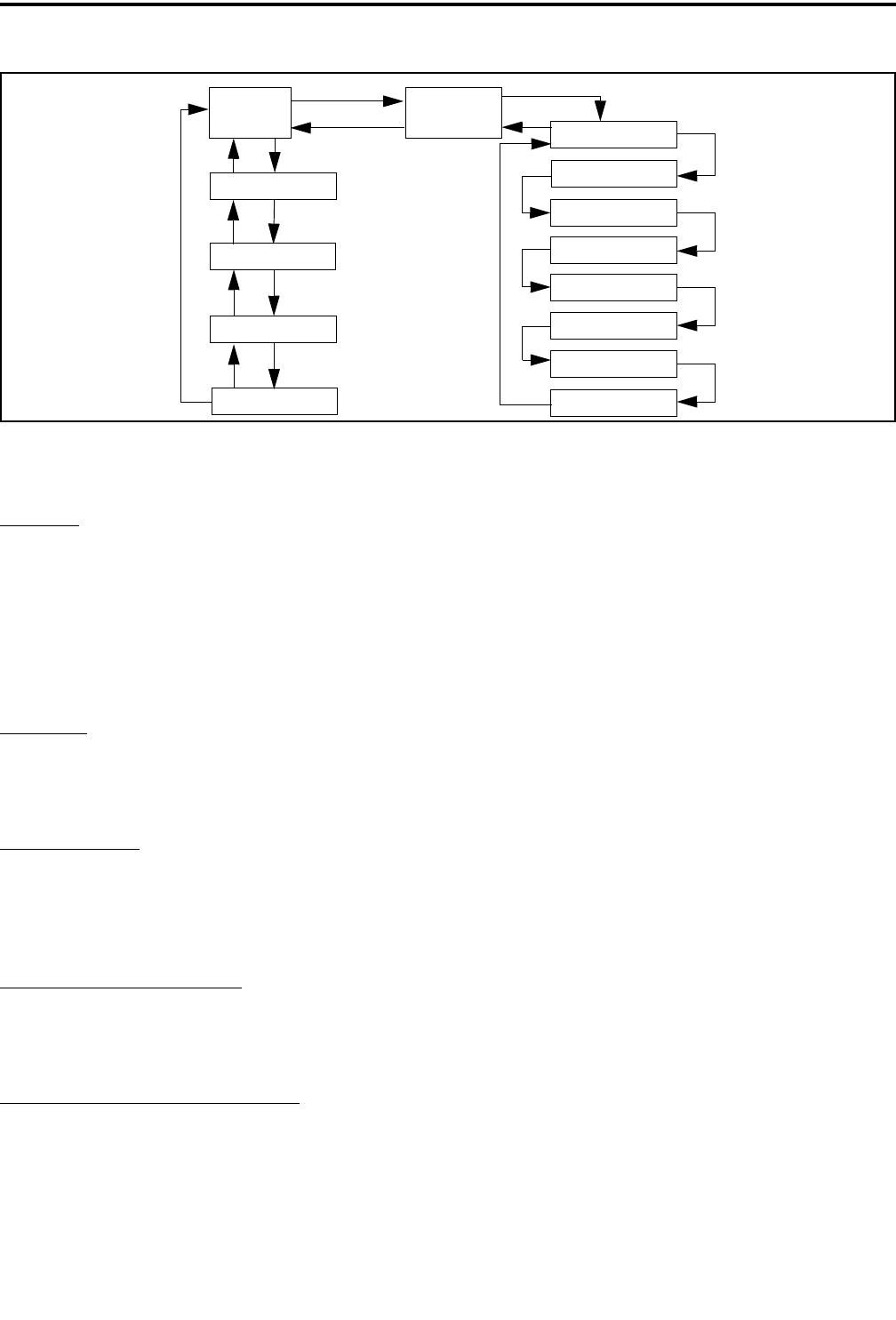
OPERATION
2-26 September 2001
Part No. 001-5100-001
Figure 2-3 Keypad Programming Flowchart
RAD
PARM
Clone?
Rx Freq
Tx Freq
Rx CG/NAC
Tx CG/NAC
Tx Power
TOT On-Off
*
#
Zone No. ZONE x
CLR key CHAN xx
#
*#
#
#
#
#
#
#
Wide/Nar Band
#
Tx Timer
Penalty Timer
Conver. Timer
#
#
#
*
*
*
#
Six Beeps
•The paged radio received the page and acknowl-
edged it (Section 2.7.7).
•The message that was sent has been received and
acknowledged (Section 2.7.8).
•The status condition that was sent has been received
and acknowledged (Section 2.7.9).
Two Beeps
•The emergency alarm condition was acknowledged
(Section 2.7.10).
Gurgle-Like Tone
•Dynamic regrouping has occurred (Section 2.7.13).
•Dynamic regrouping has occurred but the
regrouping channel is not selected (Section 2.7.13).
Four Low Tones (Busy Signal)
•The radio system is busy or a busy condition exists
when making a telephone call.
Four Alternating High and Low Tones
•A channel is available after a busy condition
occurred (SMARTNET/SmartZone only).
2.9 KEYPAD PROGRAMMING
2.9.1 INTRODUCTION
Keypad programming is available with full
keypad (18-key) models if the Keypad Programming
option switch is programmed. It is then selected by
pressing this switch and entering the programming
password. This password is a series of eight digits
selected preprogrammed using PCTrunk, and it
prevents unauthorized changing of radio program-
ming. The default password is eight zeros, and the
ENT (F4) key must be pressed after the digits are
entered. This password is not user reprogrammable.
Keypad programming allows conventional
channel parameters such as the transmit and receive
frequency and Call Guard squelch code to be changed.
In addition, several conventional mode timers can be
programmed. It cannot be used to reprogram disabled
or SMARTNET/SmartZone channels.
2.9.2 MENU STRUCTURE
When the Keypad Programming mode is selected
by pressing the option switch and entering the pass-
word, “Pgm” is displayed along with the first menu
parameter “RAD PARM”. The flowchart in Figure 2-3

OPERATION
2-27 September 2001
Part No. 001-5100-001
shows the keypad programming mode menu structure
for this radio.
The information which follows describes how the
various parameters are programmed. When program-
ming is complete, exit the keypad programming mode
by turning power off. Do not turn power on again for a
short time so that the radio has time to copy the
settings to memory.
2.9.3 CLONING
The cloning mode is used to program one trans-
ceiver with another with identical information. A
special cloning cable is required to connect the trans-
ceivers together. To enter this mode, on the master
(sending) radio, press the # (pound) key with “RAD
PARM” displayed. The clone mode is then indicated
by “CLONE?”. To return to “RAD PARM” without
cloning, press the key. To clone a radio, connect the
cloning cable, power up the slave (receiving) radio,
and press the ENT key on the master (sending) radio.
When cloning is successfully completed, “RAD
PARM” is again displayed. Encryption keys are not
transferred.
2.9.4 TIMER PROGRAMMING
The menus to program the following timers are
accessed by repeatedly pressing the # key with “RAD
PARM” displayed. To return to the previous adjust-
ment, press the key.
TX TMR - Programs the transmit time-out timer (see
page 7). Press the and keys to decrement/incre-
ment the timer in 15-second steps (“0” disables it).
When the desired value is displayed, store it by
pressing the ENT (F4) key.
PEN TMR - Programs the penalty timer (see
page 12). Press the and keys to decrement/
increment the timer in 15-second steps (“0” disables
it). When the desired value is displayed, store it by
pressing the ENT (F4) key.
CONV TMR - Programs the conversation timer (see
page 12). Press the and keys to decrement/
increment the timer in 30-second steps (“0” disables
it). When the desired value is displayed, store it by
pressing the ENT (F4) key.
2.9.5 CHANNEL PROGRAMMING
Zone Selection
The zone containing the channel to be
programmed must be selected if applicable. To do this,
with “RAD PARM” displayed press the key corre-
sponding to the zone containing the channel. Alterna-
tively, press the and keys to scroll through the
programmed zones and the “RAD PARM” selection.
The zone selection mode is indicated by “ZONE x”.
To return to “RAD PARM”, press the CLR key. To
proceed to channel parameter programming described
in the next section, press the # key.
Channel Selection
The channel to be programmed must be selected.
To do this, press the # key with “ZONE x” displayed
as described in the preceding section. The display then
indicates “CHAN xx”. Then to select the desired
channel, press the and keys to scroll through
the programmed channels or enter the channel number
directly using the number keys. Disabled or
SMARTNET/SmartZone channels cannot be selected.
To exit back to the “ZONE x” display, press the
key with “CHAN xx” displayed. To save the selec-
tion and proceed with the channel parameter program-
ming described in the next section, press the ENT or
# key.
Channel Parameter Programming
After selecting the channel to be programmed as
described in the preceding section, the following
channel parameters can be programmed. To scroll
through these parameters, press the ENT or # key with
“CHAN xx” displayed. To go back to the previous
field, press the key. The squelch control parameters
are unique to the type of conventional channel selected
(analog or Project 25).
Channel Spacing - Selects either “WIDE” or
“NARROW” band channel spacing on analog chan-
nels only. Press the and keys to toggle between
“WIDE” and “NARROW”, and when the desired
setting is displayed, save it and proceed to the next
parameter by pressing the ENT or # key.
*
*
*
*

OPERATION
2-28 September 2001
Part No. 001-5100-001
Receive Frequency - When the Rx icon is indicated
to the left of Pgm and a frequency or eight zeros is
displayed, the receive channel frequency can be
programmed. Press the CLR key to clear the current
frequency and then type in the new frequency. When
the desired frequency is displayed, save it and proceed
to the next parameter by pressing the ENT or # key.
Transmit Frequency - When the Tx icon is indicated
to the left of Pgm and a frequency or eight zeros is
displayed, the transmit frequency is programmed the
same as the Receive Frequency above.
Squelch Control (Analog Channels)
Receive CTCSS/DCS - When “TN xxxx” or “DIG
xxx” is displayed with the Rx icon indicated to the left
of Pgm, the receive Call Guard (CTCSS/DCS) code
can be programmed. Press the CLR key to clear the
current code and toggle between the CTCSS (tone)
and DCS (digital) modes. Press the and keys to
scroll through the available codes. When the desired
code is displayed, save it and proceed to the next
parameter by pressing the ENT or # key.
Transmit CTCSS/DCS - When “TN xxxx” or “DIG
xxx” is displayed with the Tx icon indicated to the left
of Pgm, the transmit Call Guard (CTCSS/DCS) code
can be programmed the same as the Receive CTCSS/
DCS above.
Squelch Control (Project 25 Channels)
Receive NAC - When “NAC xxx” is displayed with
the Rx icon indicated to the left of Pgm, the receive
Network Access Code (NAC) can be programmed.
This can be any number from 0-4095. Press the CLR
key to clear the current code and then enter the desired
code using the number keys. When the desired code is
displayed, save it and proceed to the next parameter by
pressing the ENT or # key.
Transmit NAC - When “NAC xxx” is displayed with
the Tx icon indicated to the left of Pgm, the receive
NAC can be programmed the same as the Receive
NAC described above.
Transmit Power Level - When any of the following
indications are displayed, the power output level for
the channel can be programmed. Press the and
keys to scroll through the choices. When the desired
setting is displayed, save it and proceed to the next
parameter by pressing the ENT or # key.
•POWER HI - High transmit power
•POWER LO - Low transmit power
•POWER SW - Switchable power selectable by
the High/Low power switch. This choice is not
available if that switch is not programmed.
Time-Out Timer - When “TOT ON” or “TOT OFF”
is displayed, the time-out timer can be enabled or
disabled on the current channel. Press the and
keys to toggle between the on and off mode. To return
to the “CHAN xx” display, press the ENT or # key.
Programming Additional Channels and Exiting
Programming Mode
•To program another channel in the current zone,
press the ENT or # key to redisplay “CHAN xx” and
then repeat starting with “Channel Selection”.
•To program channels in another zone, press the
key with “CHAN xx” displayed to display “ZONE
x” and repeat this procedure starting with “Zone
Selection”.
•If programming is complete, exit the keypad
programming mode by turning power off. Do not
turn power on again for a short time to allow the
radio time to copy the settings into memory.
*