E F Johnson 2425770 Vantage 700/800 MHz Portable Radio User Manual
E. F. Johnson Company Vantage 700/800 MHz Portable Radio Users Manual
UserManual.wiki
>
E F Johnson
>
2425770 User Manual
>
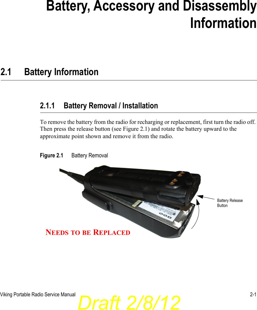
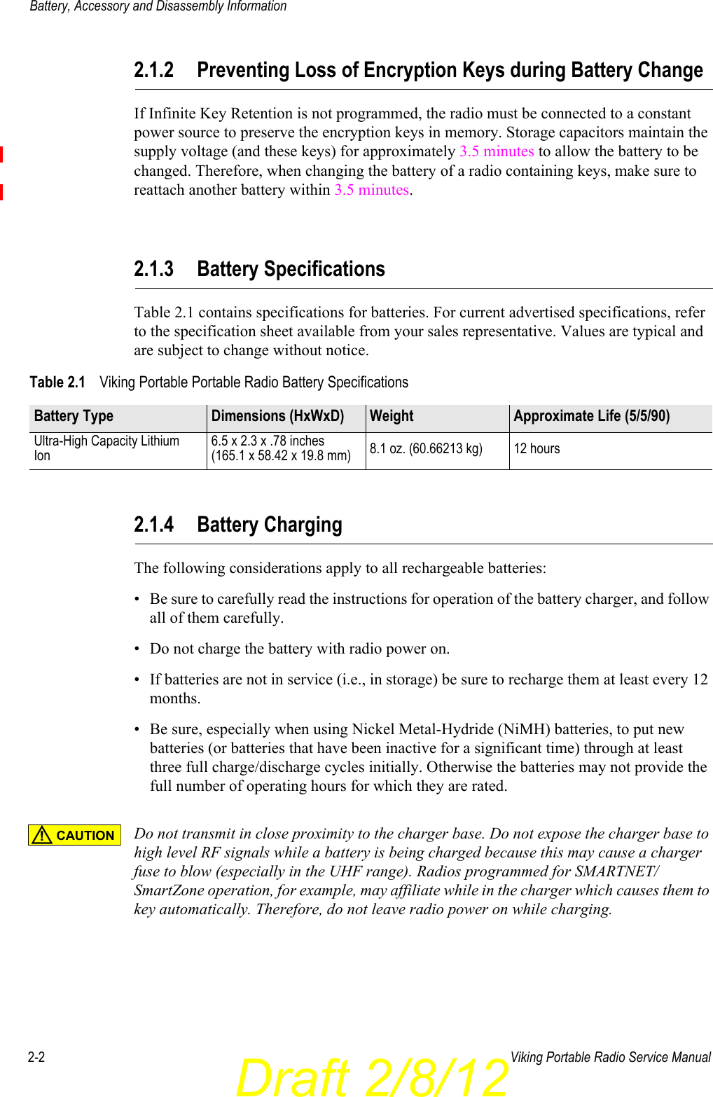
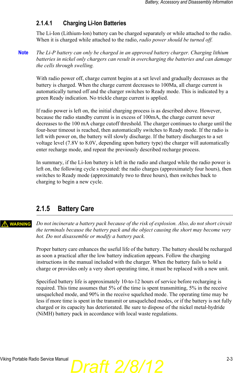
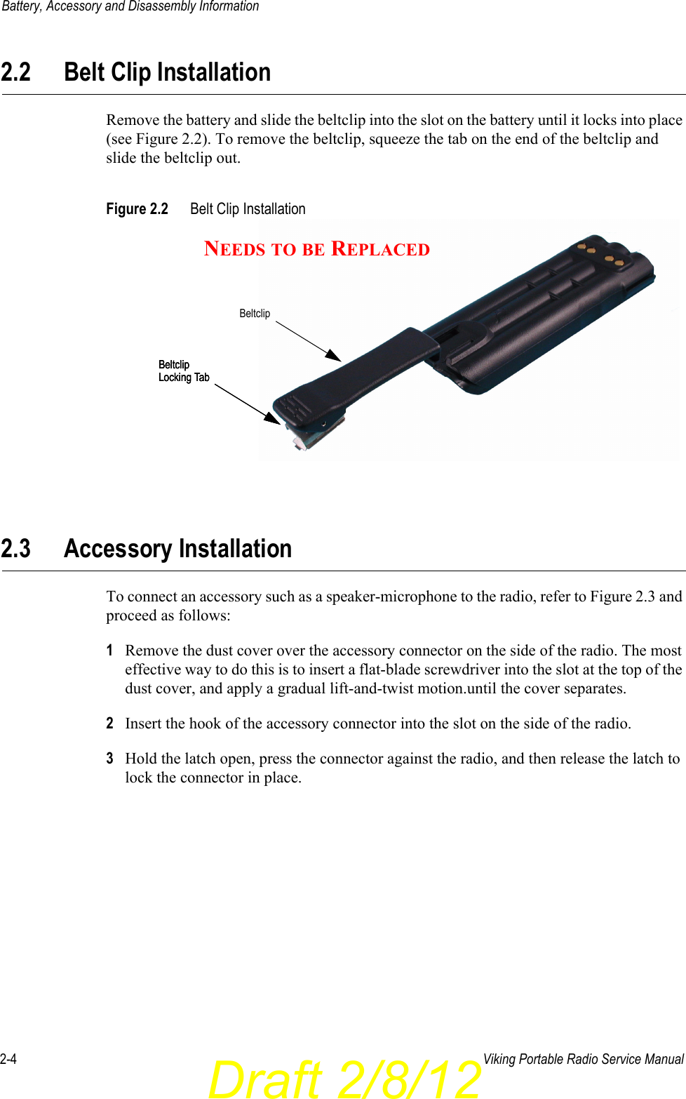
battery information
Contents
1.
battery information
2.
user manual
battery information
Navigation menu
Upload a User Manual
Namespaces
Wiki Guide
HTML
PDF
Info
Views
User Manual
Discussion / Help
Navigation