E F Johnson 2425770 Vantage 700/800 MHz Portable Radio User Manual Viking Portable 600 Radio Operating Manual
E. F. Johnson Company Vantage 700/800 MHz Portable Radio Viking Portable 600 Radio Operating Manual
Contents
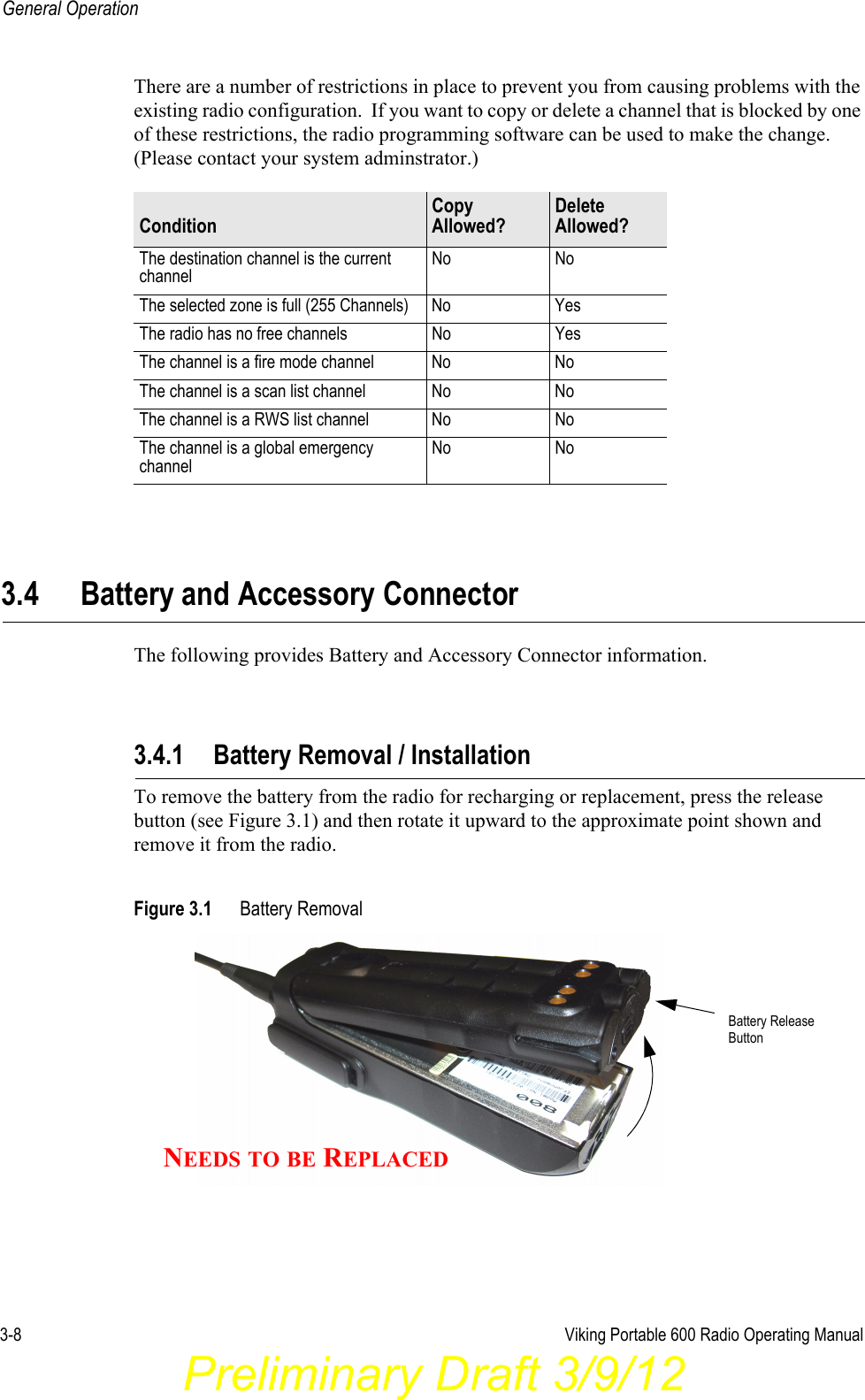
- 1. battery information
- 2. user manual
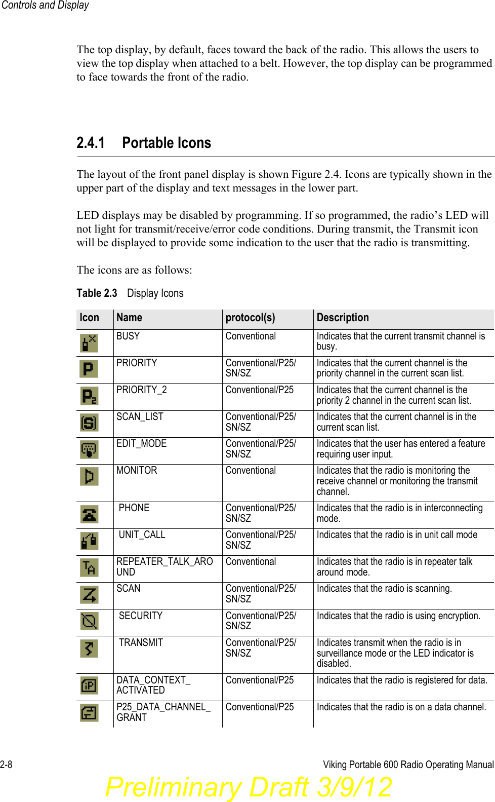
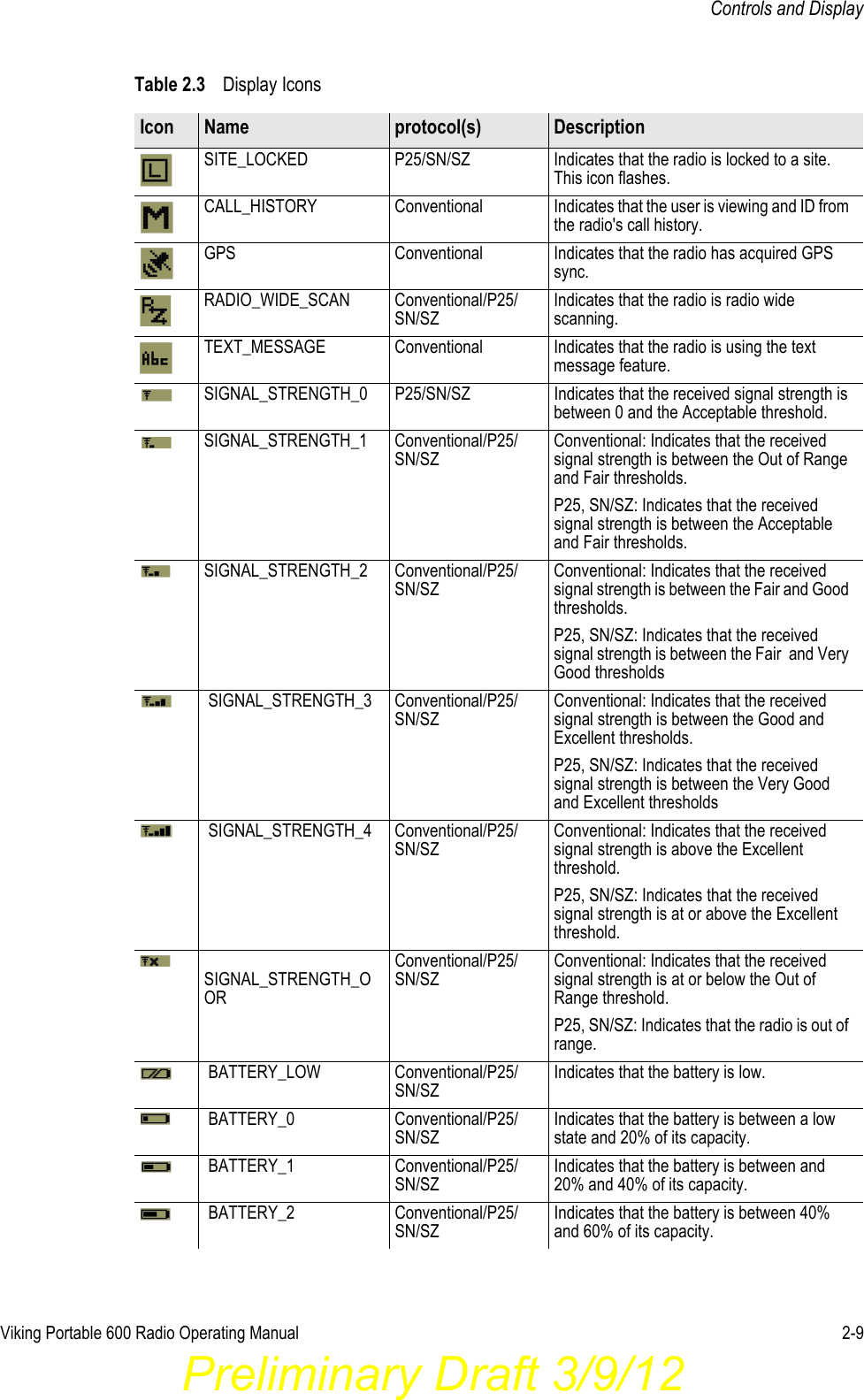
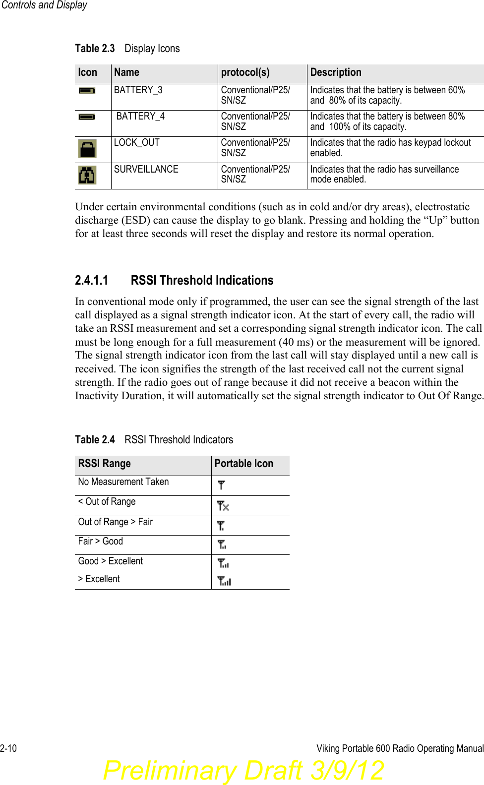
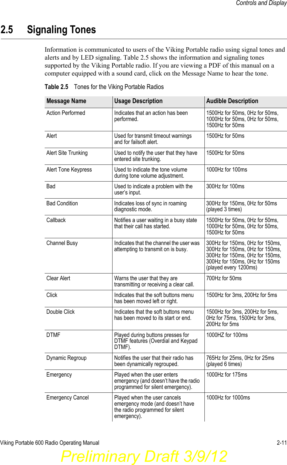
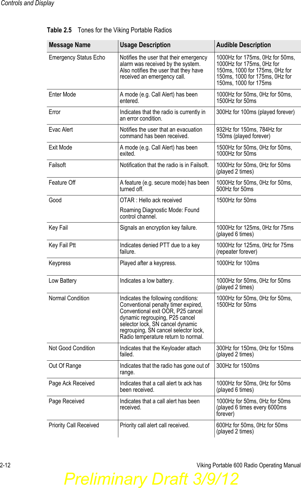
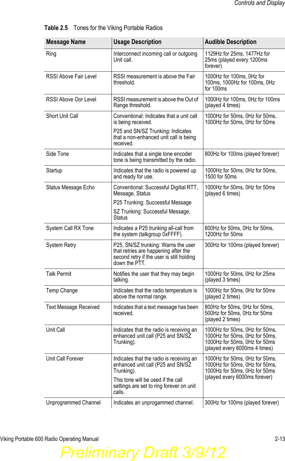
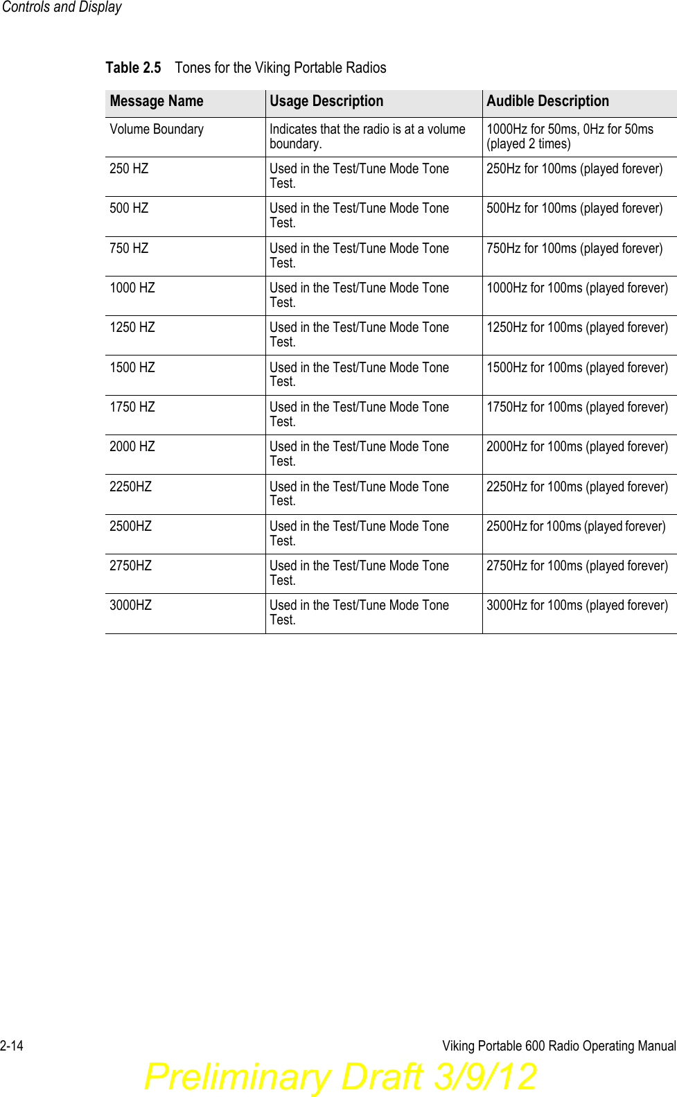
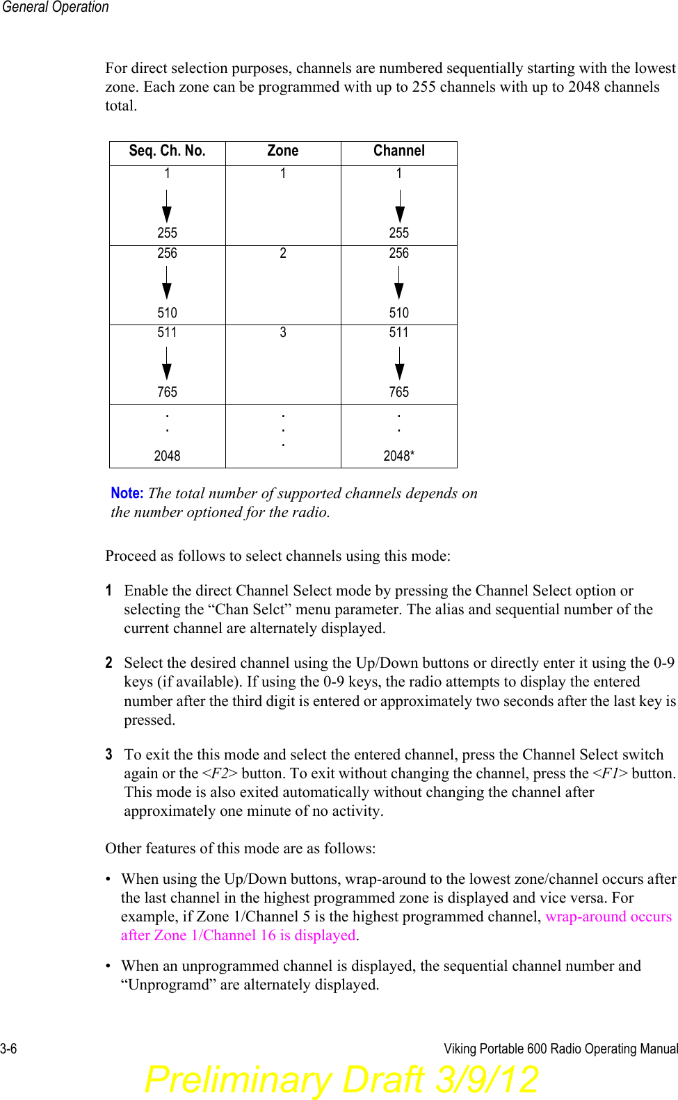
user manual