E M S Electro Medical Systems GRDLNBPVMEO Intracorporeal lithotripter User Manual 1 2ANZC GRDLNBPVMEO
E.M.S. Electro Medical Systems S.A. Intracorporeal lithotripter 1 2ANZC GRDLNBPVMEO
Contents
- 1. User manual 1 - 2ANZC-GRDLNBPVMEO.pdf
- 2. User manual 2 EN- 2ANZC-GRDLNBPVMEO.pdf
- 3. User manual 2 FR- 2ANZC-GRDLNBPVMEO.pdf
User manual 1 - 2ANZC-GRDLNBPVMEO.pdf
INSTRUCTIONS FOR USE
FT-231
FT-232

2SWISS LITHOCLAST BLAST - FB-610/EN 23-JUNE-2017 / EMS CONFIDENTIAL
3
Please Read this First!
Thank you for purchasing this new EMS product. It meets
the highest quality and safety standards.
We would be pleased to answer your questions and we
welcome your suggestions. We do, of course, provide
support in case of technical problems. Please contact
your EMS authorized service center or your dealer
directly.
We wish you lots of success!
EMS
About this Manual
Please note that the English version of this manual is the
source from which all translations are derived. In case of
any discrepancy, the binding version is the English text.
These operating instructions are to ensure the correct
installation and use of this product. Always keep these
instructions close at hand.
Please read these operating instructions carefully as
they explain important details and procedures. Please
pay special attention to the safety precautions.
To prevent injury to people and damage to property,
please follow the corresponding directives. They are
marked as indicated:
Caution:
Risk of patient or user injury. Risk of damage
to the product or environmental harm.
Note:
Useful additional information and hints.
Intended Use
The product is intended for the fragmentation and removal
of urinary tract calculi in the kidney, ureter, and bladder.
Operating mode
The product can deliver ultrasound and ballistic energies
through a single probe simultaneously, or separately
to fragment stones. The product can extract stone
fragments through the probe while delivering energy or
without delivering energy. The product is able to collect
the stone fragments for analysis.
Intended User
The product must be used by qualied operating room
personnel (with extensive training in urology) in hospitals,
clinics and medical universities to treat affected patients
of any age.
It is intended to be reprocessed by trained reprocessing
personnel, biomedical services, or by an external repro-
cessing contractor.
Contraindications and Patient Population
Use of the product is contraindicated in patients with any
of the following conditions:
• Active bleeding disorders,
• Solitary functioning kidney,
• Creatinine greater than or equal to 3 µg %,
• During pregnancy,
• Stricture and obstruction problems,
• An implanted electrical stimulator (e.g. pacemaker).
Potential Complications
Potential complications associated with fragmentation of
urinary tract calculi by ballistic and/or ultrasound energy
include:
• Perforation,
• Hemorrhage,
• Lesion,
• Stone migration,
• Pain/colic,
• Macroscopic hematuria,
• Infection,
• Ureteral obstruction.
4SWISS LITHOCLAST BLAST - FB-610/EN 23-JUNE-2017 / EMS CONFIDENTIAL
CONTENTS
1. SAFETY PRECAUTIONS 5
2. COMPONENTS 6
3. INSTALLATION 8
3.1. INSTALLING THE CONSOLE 8
3.2. FILLING THE COOLING SYSTEM 8
3.3. CONNECTING THE CONSOLE TO THE
EQUIPOTENTIAL CONDUCTOR 10
3.4. CONNECTING THE VIDEO CORD
(OPTIONAL) 10
3.5. INSTALLING THE PEDAL 11
3.6. INSTALLING THE STONE CATCHER 11
3.7. INSTALLING THE SINGLE-USE FLUID
MANAGEMENT SYSTEM SET (OPTIONAL)
AND REPLACEMENT POUCH 13
3.8. CONNECTING THE STERILIZED
HANDPIECE TO THE CONSOLE 13
3.9. INSTALLING A PROBE ON THE
HANDPIECE 14
3.10. CONNECTING THE POWER CORD 14
4. GETTING STARTED 15
4.1. STARTING THE DEVICE 15
4.2. ADJUSTING THE PARAMETERS 15
4.3. EQUIPMENT DATA 17
5. TREATMENT 18
5.1. FUNCTIONAL TESTS 18
5.2. PROBE INSERTION 19
5.3. TREATMENT SETTINGS 19
5.4. ADAPTING SUCTION FLOW RATE 21
5.5. STARTING TREATMENT 21
6. POST-TREATMENT PROCEDURE 22
6.1. COMPLETING TREATMENT 22
6.2. DISCONNECTING THE HANDPIECE 23
6.3. RECORDING TREATMENT DATA 24
6.4. DISCONNECTING THE STONE CATCHER 25
6.5. ELIMINATING THE STONE CATCHER
CONTENTS 25
6.6. CONSERVING THE STONE CATCHER
CONTENTS 25
6.7. DISPOSING OF SINGLE-USE
COMPONENTS 25
6.8. SWITCHING OFF THE CONSOLE 25
7. CLEANING, DISINFECTING,
AND STERILIZING 26
7.1. MULTIUSE COMPONENTS 26
7.2. CONSOLE, PEDAL, AND CART 28
8. PRODUCT MAINTENANCE 29
8.1. COOLING LIQUID CIRCUIT MAINTENANCE 29
8.2. REPLACING FUSES 30
8.3. DOWNLOADING LOGFILE 30
9. PRODUCT STORAGE AND SHIPPING 31
9.1. EMPTYING THE COOLING LIQUID CIRCUIT
31
9.2. SHIPPING THE PRODUCT 32
10. PRODUCT DISPOSAL 33
11. EMS TECHNICAL SUPPORT 33
12. TROUBLESHOOTING 34
12.1. MANUAL HANDPIECE UNLOCKING 34
12.2. WEAK SUCTION 34
12.3. PROBE NOT COMPATIBLE WITH THE
ENDOSCOPE 34
12.4. DISPLAYED ERROR MESSAGES 34
13. FORMER ELECTROMAGNETIC
COMPATIBILITY 37
14. NEW ELECTROMAGNETIC
COMPATIBILITY 40
15. TECHNICAL DATA 42
16. SYMBOLS 43
17. APPENDIX 46
17.1. PROBE COMPATIBILITY TABLE 46
17.2. FCC AND IC 46
5
1. SAFETY PRECAUTIONS
EMS and the distributor of this product accept no liability for direct or consequential injury or damage resulting from
improper use, arising in particular through non-observance of the operating instructions, or improper preparation and
maintenance.
Instructions for use are explicitly given at installation by an EMS representative.
Before using this product, please carefully read,
understand, and follow the recommendations in the
instruction manual. Failure to observe the operating
instructions may result in the patient or user suffering
serious injury or the product being damaged. This
product may only be applied for its intended use
by qualified personnel and for the applications
described in this manual. If the product is used in
combination with other instruments, please refer to
their instruction manual.
Do not use this product in the presence of ammable
anesthetics or oxidizing gases (such as nitrous
oxide (N2O) and oxygen) or in close proximity
to volatile solvents (such as ether or alcohol), as
explosion may occur.
Before using the product, inspect for any damage.
Do not use if the product is damaged. Use original
EMS spare parts and accessories only.
Do not modify or repair the product yourself. Please
contact an EMS authorized service center.
To avoid risk of contamination, before each use,
always clean, disinfect and sterilize the product
according to the EMS reprocessing instructions.
To avoid injury or damage, make sure that the
fragmentation energy is supplied only upon contact
of the probe with the stone. Do not touch the probe
during activation.
When the mains power switch is in the “0” position,
the product is disconnected from the supply network.
Do not tilt or ip the console without rst having
purged the cooling system. Always empty the
cooling circuit before transport. Please refer to
Emptying the Cooling Liquid Circuit section.
Do not start treatment without ensuring that a
back-up probe is available.
Make sure that the handpiece, handpiece fluid
aspiration connector, and re-usable wrenches are
sterilized before proceeding with installation.
Any serious incident that has occurred in relation to
the product should be reported to the manufacturer
and the competent authority.
6SWISS LITHOCLAST BLAST - FB-610/EN 23-JUNE-2017 / EMS CONFIDENTIAL
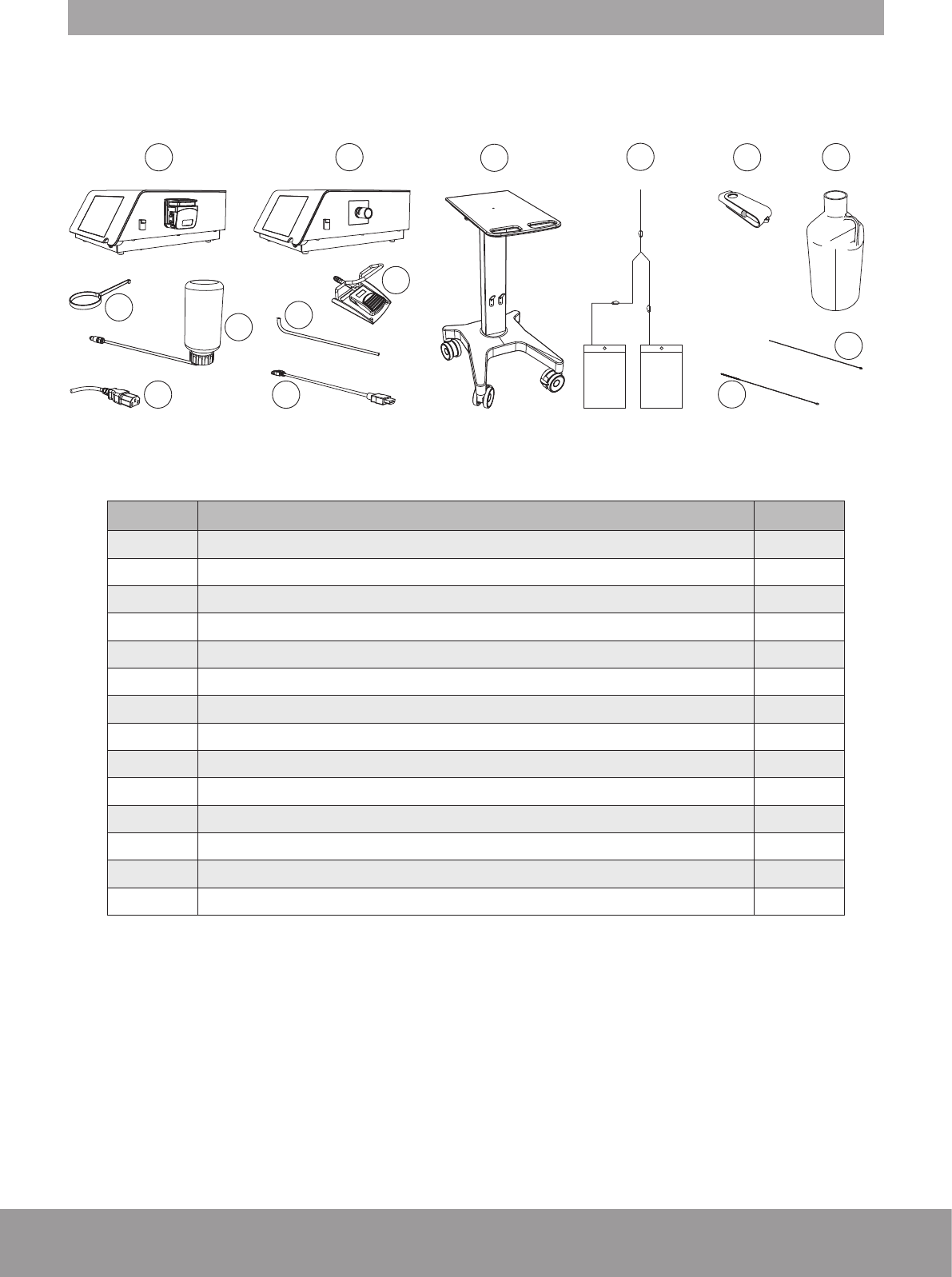
2. COMPONENTS
The components provided for your device will vary, according to your conguration.
12345
8
9
7
6
10
11
12
14
13
NON STERILE ZONE
REF DESIGNATION QTY
1 Console (with peristaltic pump) or 1
2 Console (with pinch valve) 1
3 Cart - optional 1
4 Fluid management system - optional 1
5 USB key 1
6 2.5 L Demineralized water 1
7 Stone catcher support 1
8Cooling system lling kit 1
9 Power cord 1
10 Wired pedal 1
11 Draining tube 1
12 External video cord - optional 1
13 Cleaning brush 1
14 Cleaning rod 1
Figure 1
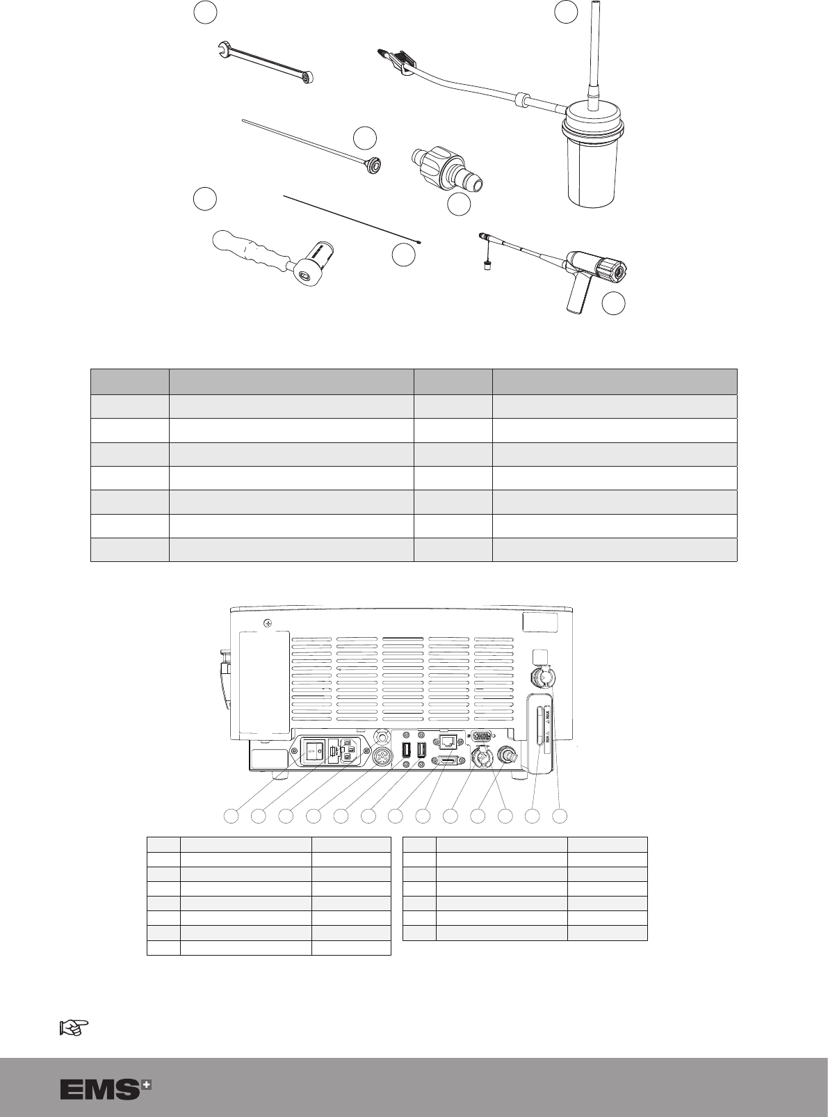
7
15 16
17
18
19
20
21
STERILE ZONE
REF DESIGNATION QTY STERILE STATE
15 Standard wrench 1 To be sterilized before use
16 Stone catcher - optional 1 Provided sterile
17 Multiuse torque wrench 1 To be sterilized before use
18 Probe 1 Provided sterile
19 Unclogging rod 2 To be sterilized before use
20 Aspiration plug 1 To be sterilized before use
21 Handpiece 1 To be sterilized before use
Figure 2
1
2
4
3
5
6
8
7
11
9
10
13
12
REF
DESIGNATION
TO BE USED
1
Mains power switch
YES
2
Power supply connector
YES
3
Bus bar
YES
4
Pedal cord connector
YES
5
USB connector
YES
6
USB connector
YES
7
HDMI connector
YES
REF
DESIGNATION
TO BE USED
8
RJ45 connector
NO
9
Outlet connector
YES
10
Air plug connector
YES
11
Sub-D
NO
12
Level indicator
YES
13
Filling inlet connector
YES
Figure 3
Sub-D and RJ-45 (After Sales only).
8SWISS LITHOCLAST BLAST - FB-610/EN 23-JUNE-2017 / EMS CONFIDENTIAL
3. INSTALLATION
Please make sure that you have all the required parts
and tools to complete the installation of your device prior
to starting work
Refer to the Packing List.
Follow the instructions in the indicated order.
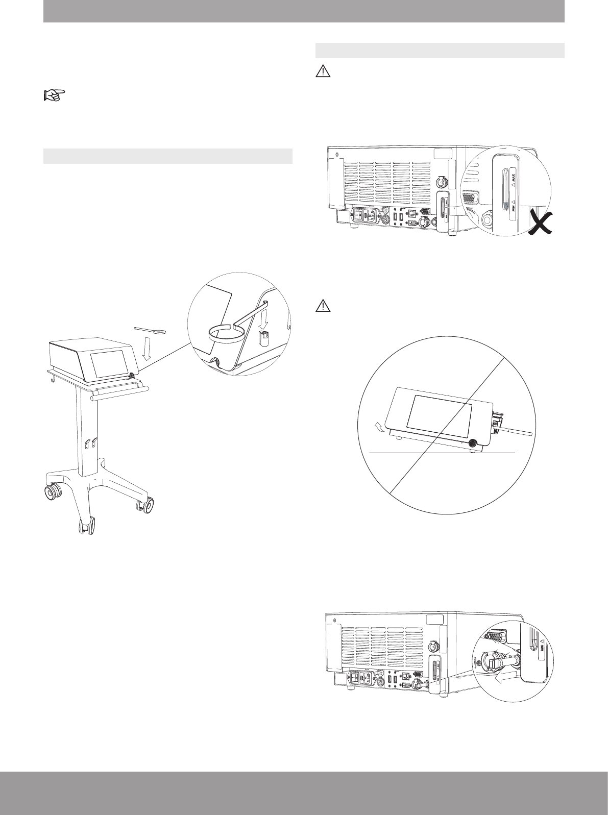
3.1. INSTALLING THE CONSOLE
1. Install the console on a at, stable surface or use the
cart (optional) designed for the console.
2. Remove the protective lm from the console.
3. Install the stone catcher support.
Figure 4
3.2. FILLING THE COOLING SYSTEM
To avoid interruptions during treatment, make sure
that the cooling liquid is above the minimum level
before use. If needed, ll the cooling system as
described below.
Figure 5
Do not tilt the console more than 10 degrees when
there is water in the cooling system.
Figure 6
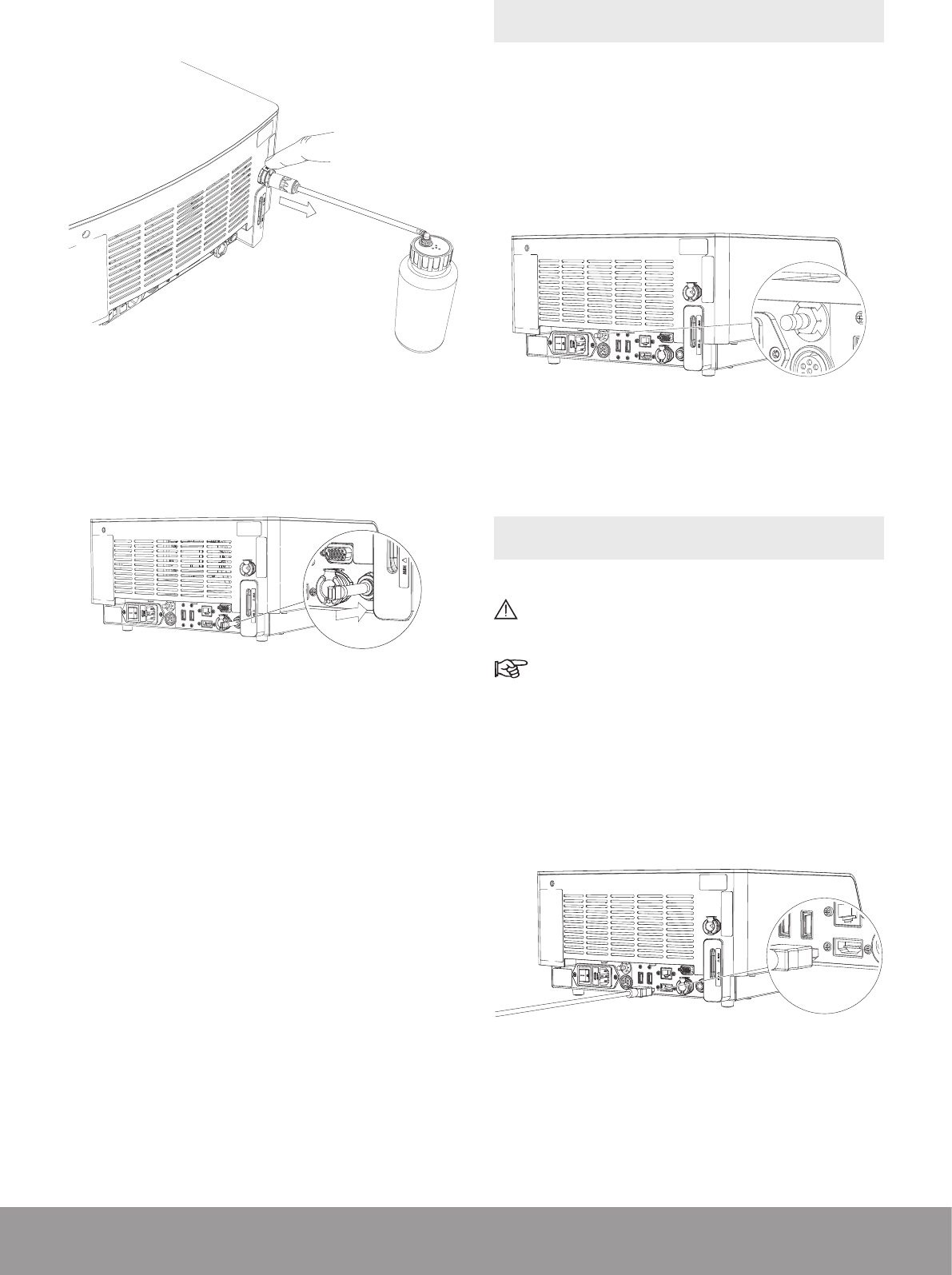
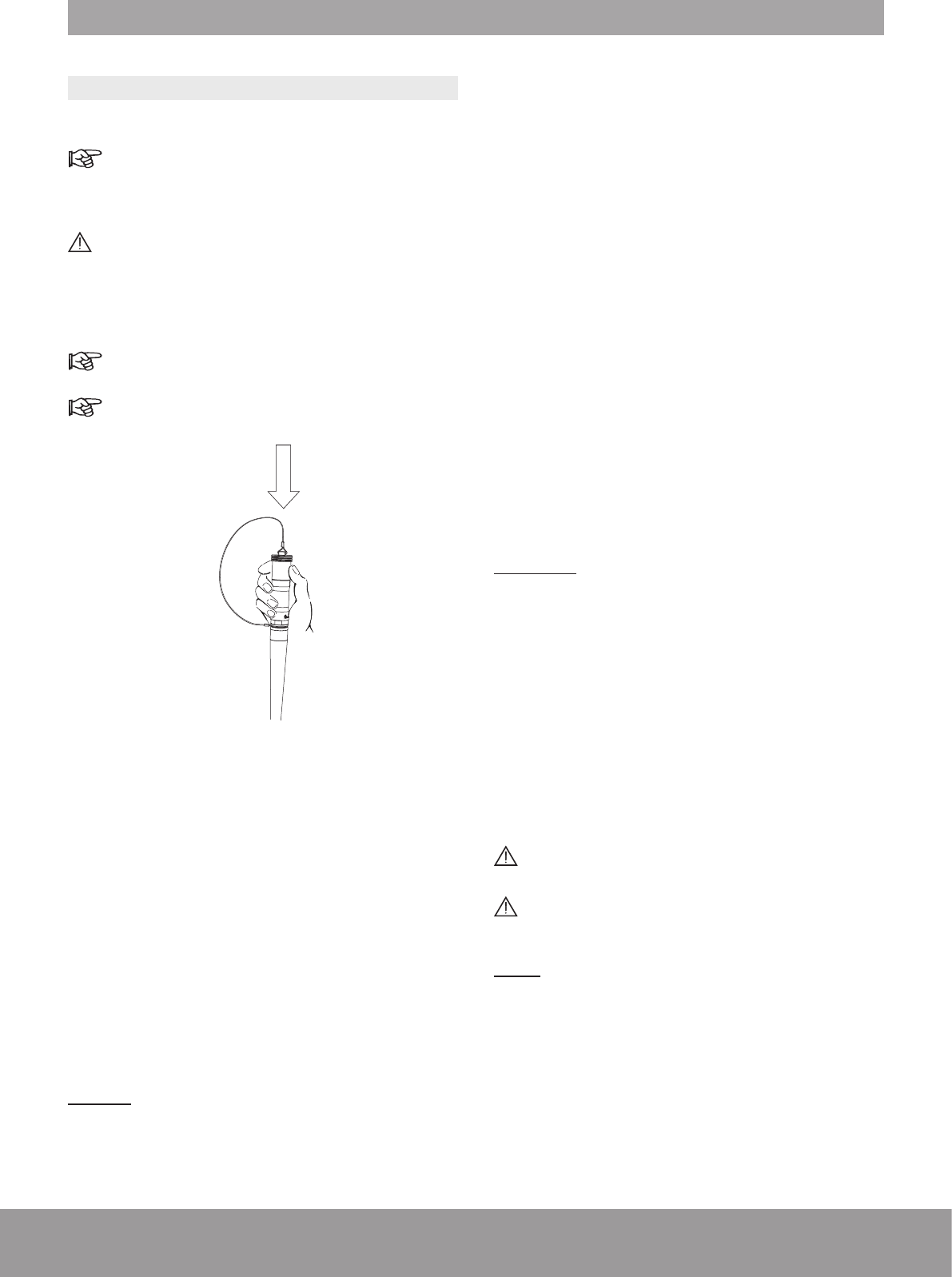
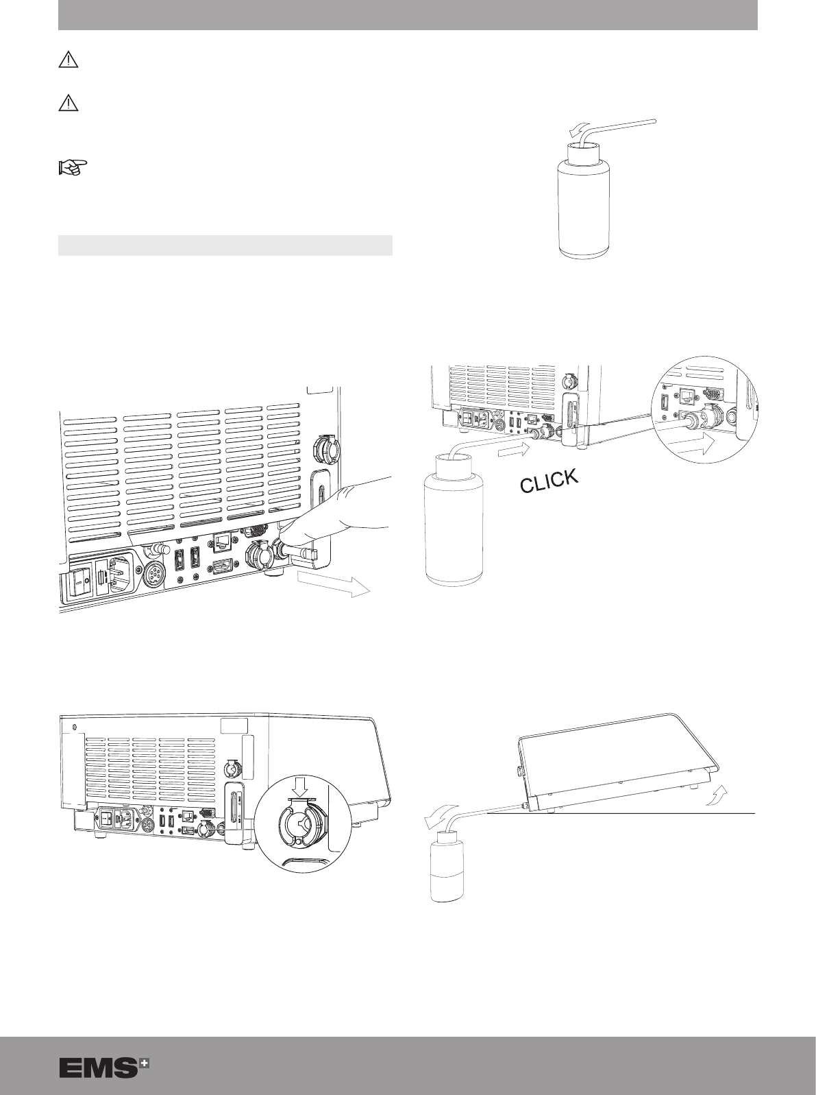
1. To remove the air vent plug, push the grey ring and
pull the air vent simultaneously.
Figure 7
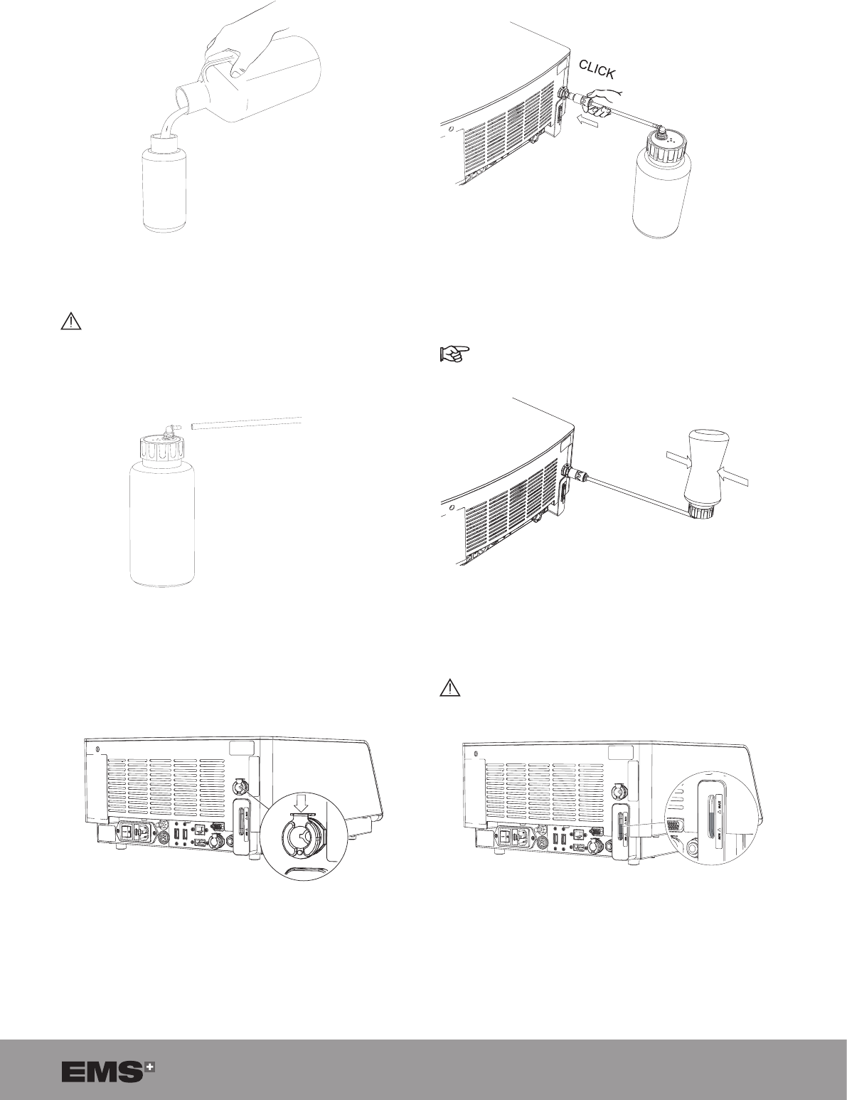
9
2. Fill the lling bottle and close it.
Figure 8
Only use demineralized water to ll the cooling
system.
3. Connect the lling tube to the lling bottle.
Figure 9
4. Make sure that the metal locking part is in the down
position.
Figure 10
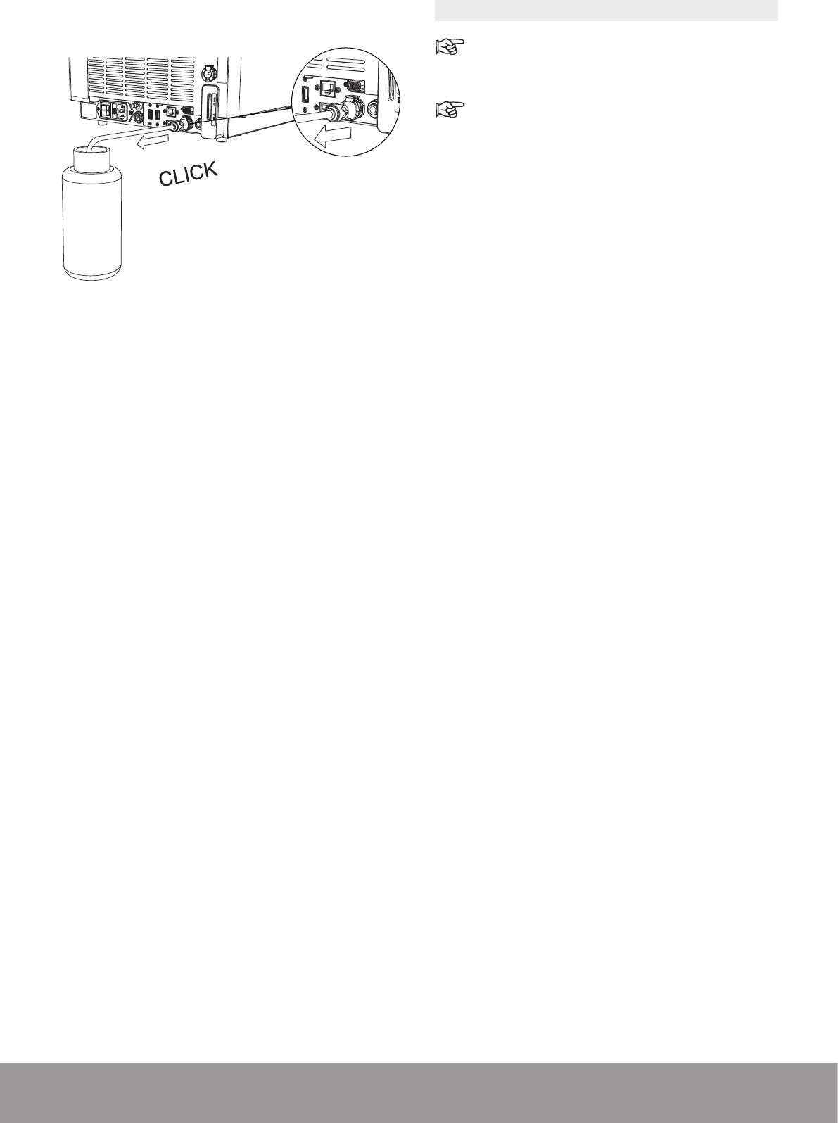
5. Push the lling tube into the lling inlet connector
until it engages.
Figure 11
6. Invert the lling bottle and squeeze it to ll the tank.
In case of over-lling, please refer to Emptying
the Cooling Liquid Circuit section.
Figure 12
Make sure that the level of water in the tank is
between the min. and max. indicators.
Figure 13
10 SWISS LITHOCLAST BLAST - FB-610/EN 23-JUNE-2017 / EMS CONFIDENTIAL
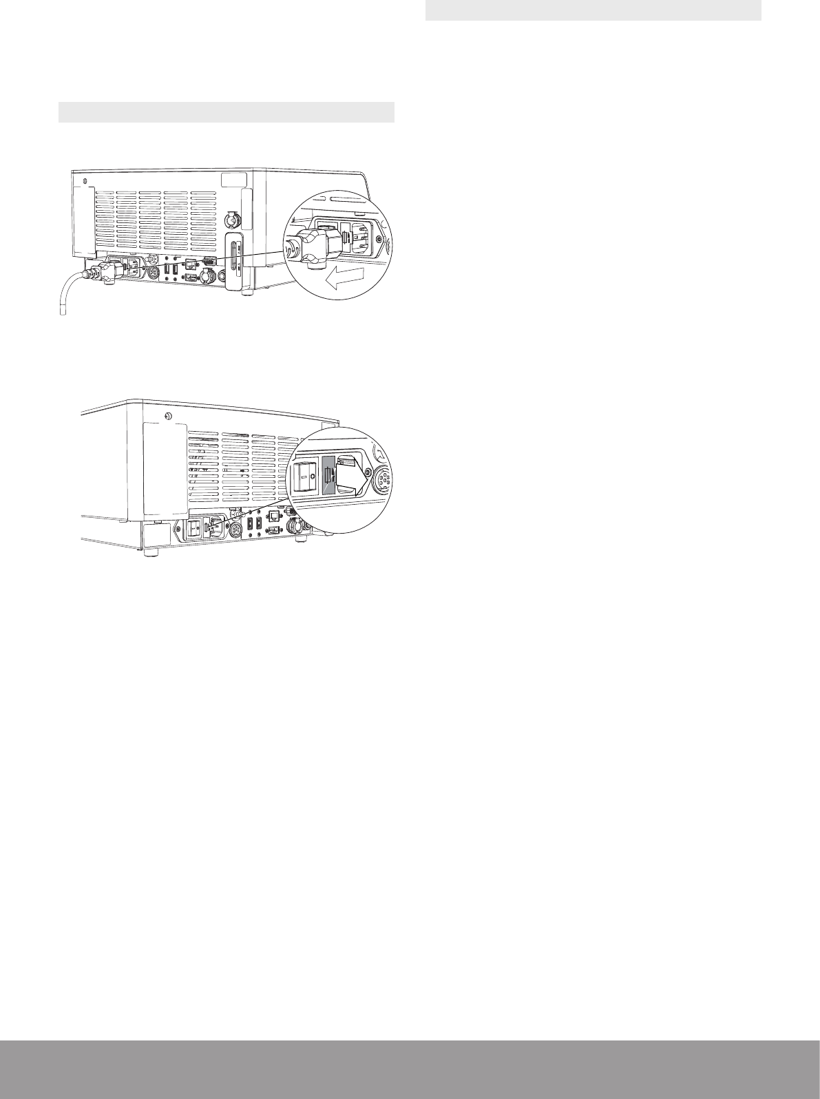
7. Push the metal locking part down to remove the lling
tube.
Figure 14
8. Re-insert the air vent plug up to the stop.
Figure 15
3.3. CONNECTING THE CONSOLE TO THE
EQUIPOTENTIAL CONDUCTOR
When applicable and according to your in-house protocol,
connect the equipotential conductor at the rear of the
console with the bus bar.
The equipotential conductor provides a connection
between the unit and the potential equalization bus bar
of the electrical installation when necessary.
Figure 16
The equipotential cable is not supplied with the console.
3.4. CONNECTING THE VIDEO CORD
(OPTIONAL)
Only connect products compliant with IEC 60950
or equivalent.
The console must be OFF before connecting the
video cord.
1. Connect the video cord to the HDMI connector at
the rear of the console and to a video monitor that
supports “Picture-in-Picture.”
2. Follow the instructions provided for the video monitor
to select the video input.
Figure 17
11
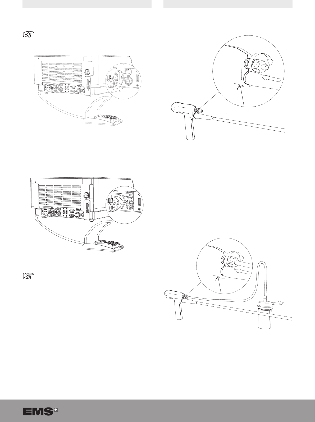
3.5. INSTALLING THE PEDAL
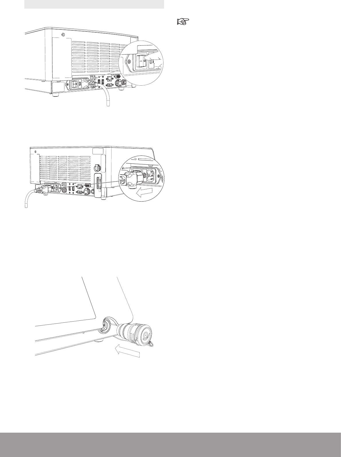
1. Connect the pedal cord to the corresponding connector
at the rear of the console.
Pay attention to the pedal cord connector indexa-
tion.
Figure 18
2. Make sure that the pedal cord connector is in the
correct position and screw the securing nut.
Figure 19
The pedal can be placed in a protective bag (not
supplied).
3. Make sure that the pedal is in an accessible location
before starting treatment.
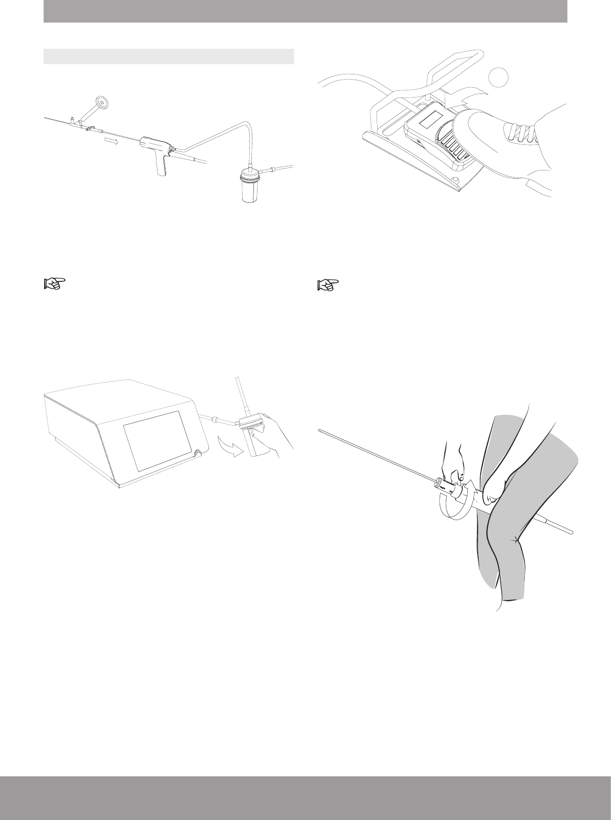
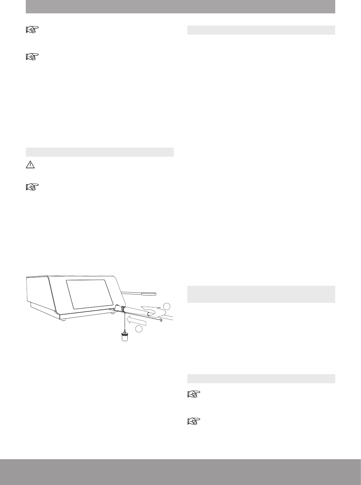
3.6. INSTALLING THE STONE CATCHER
Case 1: Use of an in-house aspiration system.
1. Screw the aspiration plug to the handpiece.
Figure 20
2. Connect the in-house aspiration system on the
aspiration plug.
3. Follow the instructions provided for the in-house
aspiration system.
Case 2: Use of a sterile, single-use Stone Catcher
provided by EMS (optional)
1. Screw the sterile connector of the stone catcher into
the handpiece.
Figure 21
12 SWISS LITHOCLAST BLAST - FB-610/EN 23-JUNE-2017 / EMS CONFIDENTIAL
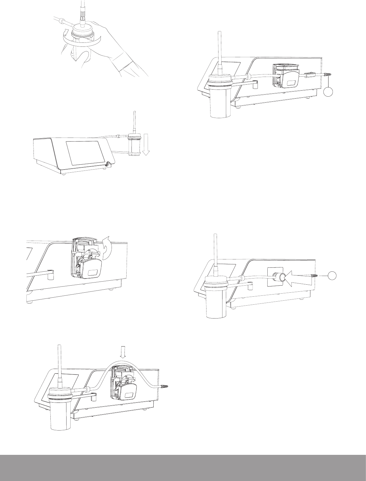
2. Tighten the Stone Catcher lid.
Figure 22
3. Insert the stone catcher into the stone catcher support.
Figure 23
4. Proceed according to your device:
• For Peristaltic Pump Device
1. Open the pump.
Figure 24
2. Place the stone catcher output tube into the pump.
Figure 25
3. Close the pump.
4. Connect the stone catcher output tube end with the
conical connector (A) to the optional uid management
system or to your uid disposal system.
A
Figure 26
5. Make sure that the output tube is not twisted or under
tension when placed in the peristaltic pump device
head.
• For Pinch Valve Device
1. To insert the stone catcher output tube into the pinch-
valve, push the pinch valve device and insert simul-
taneously the tube.
A
Figure 27
2. Connect the stone catcher output tube end with the
conical connector (A) to an external vacuum source.
13
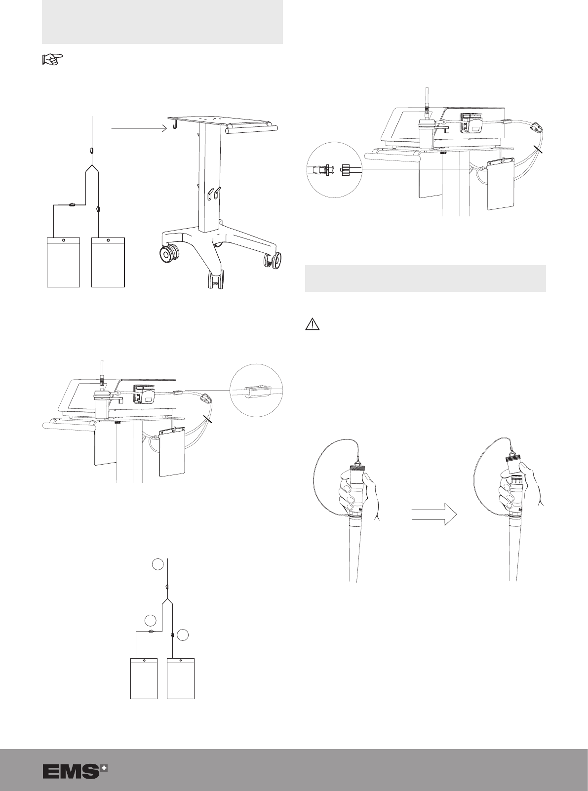
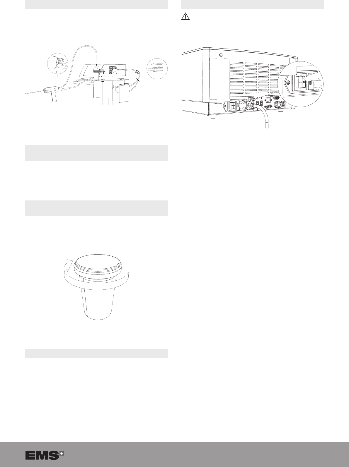
3.7. INSTALLING THE SINGLE-USE FLUID
MANAGEMENT SYSTEM SET (OPTIONAL) AND
REPLACEMENT POUCH
For the peristaltic pump device only
1. Suspend the two uid pouches, on the cart or on an
IV pole, at a level that is lower than the console.
Figure 28
2. Connect the uid management system input tube (A)
to the stone catcher output tube connector.
Figure 29
3. Close clamp (B) of one pouch to ll the rst pouch.
Clamp (C) stays open.
A
B
C
Figure 30
4. When the open pouch is lled, open the closed clamp
(B) rst.
5. Close the open clamp (C) (adjacent to the lled pouch).
6. The lled pouch can be exchanged for a new empty
pouch, using the Luer-lock connection.
Figure 31
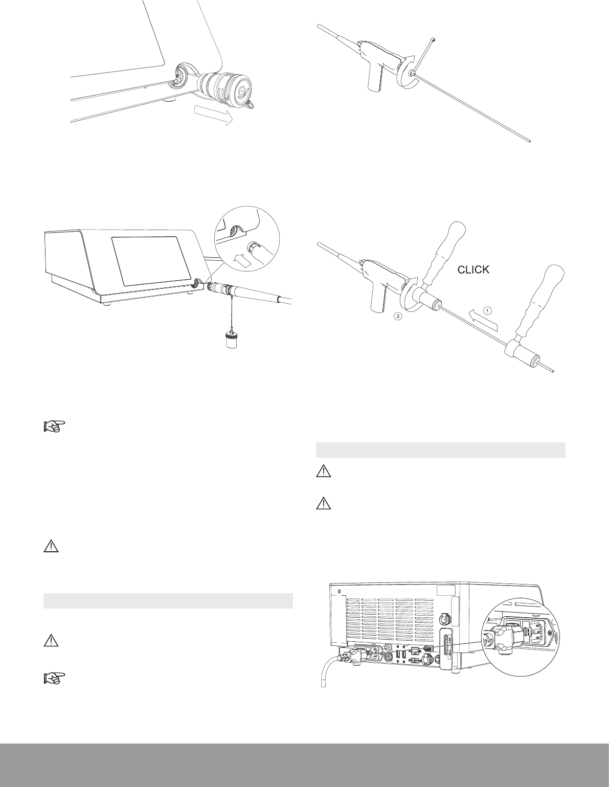
3.8. CONNECTING THE STERILIZED HANDPIECE
TO THE CONSOLE
Make sure that the handpiece connector is dry be-
fore connecting it to the console.
1. To remove the protective cap from the handpiece cord,
hold the metal part of the handpiece cable connector
and push up on the cap using your thumb and index
nger.
Figure 32
14 SWISS LITHOCLAST BLAST - FB-610/EN 23-JUNE-2017 / EMS CONFIDENTIAL
2. Remove the protective cap from the console.
Figure 33
3. Connect the handpiece to the console.
Figure 34
4. Pay attention to the orientation of the handpiece
connector.
The red dot must be on top for proper alignment.
5. Make sure that the handpiece cord does not touch
the oor and is not compressed or squeezed in any
way that might impede circulation of the cooling liquid.
6. The handpiece connection to the console is maintained
by a mechanical lock. During use, the lock icon (orange
handpiece activation icon) remains illuminated.
Do not exceed the maximum number of usage cy-
cles for the handpiece as specied in the Techni-
cal Data section.
3.9. INSTALLING A PROBE ON THE HANDPIECE
1. Select the appropriate probe.
Risk of contamination: do not use after the expiration
date on the package label.
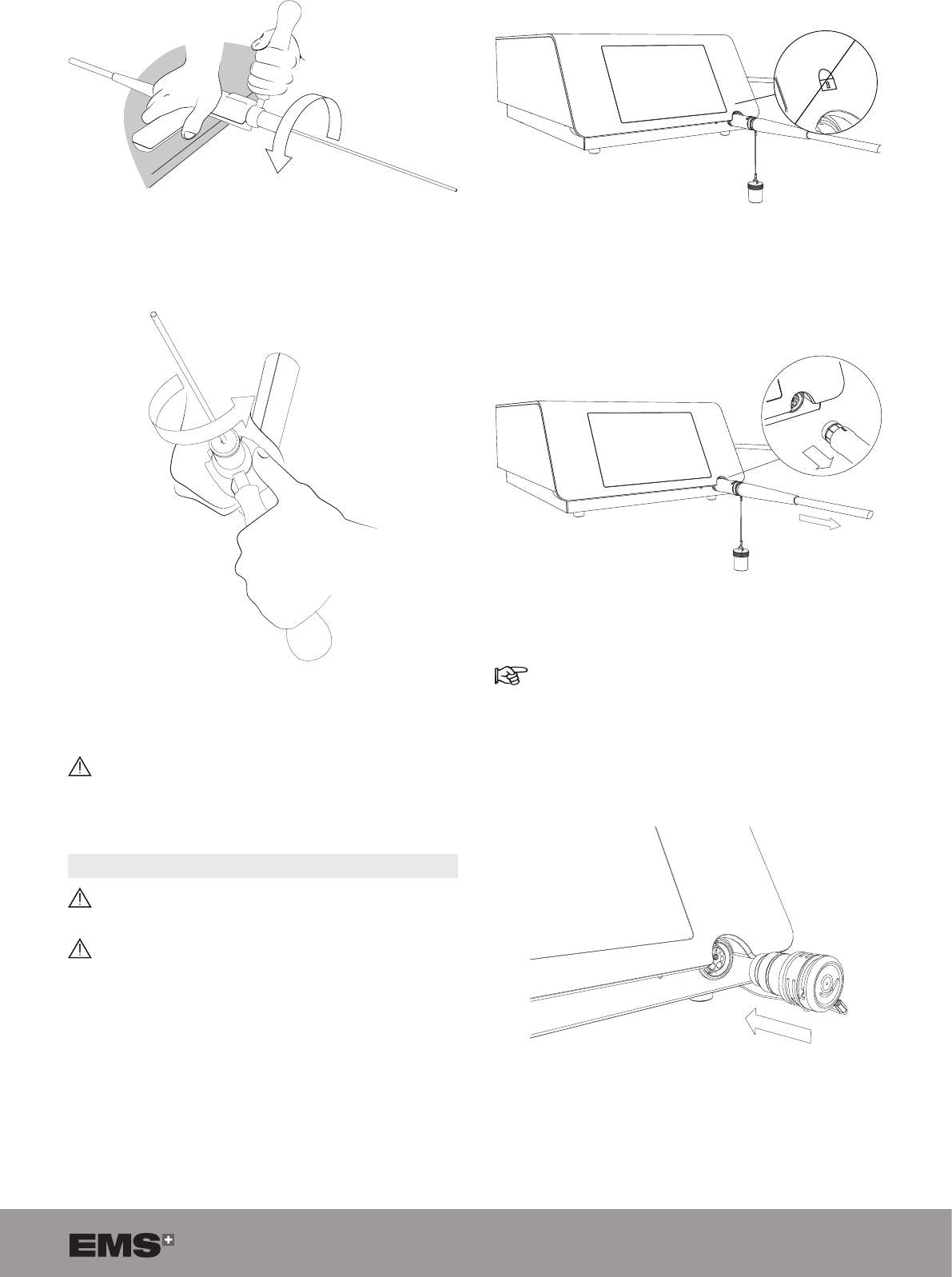
Refer to the Probe Compatibility Table section.
2. Use the wrench to rmly tighten the appropriate probe
on the handpiece.
Case 1: Standard wrench
Figure 35
Case 2: Multiuse Torque wrench
Figure 36
3.10. CONNECTING THE POWER CORD
Connect only to a FI protected mains power supply
(FI = Residual current protection).
To prevent damage to the console, make sure that
its rated voltage meets the local line voltage.
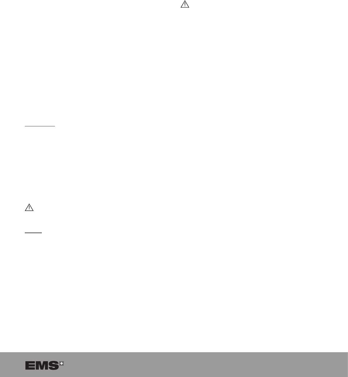
Connect the power cord to the power socket at the rear
of the console.
Figure 37
15
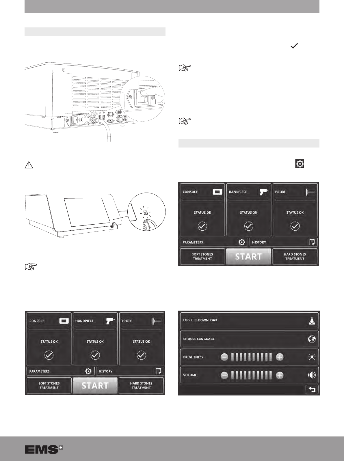
4. GETTING STARTED
4.1. STARTING THE DEVICE
1. Use the mains power switch located on the rear panel
to switch on the console.
Figure 38
Do not disconnect the handpiece while the lock
icon is switched on (in orange), since this may
result in damage.
Figure 39
When the handpiece is connected when starting
the device, the lock icon will be orange and the
purge will start.
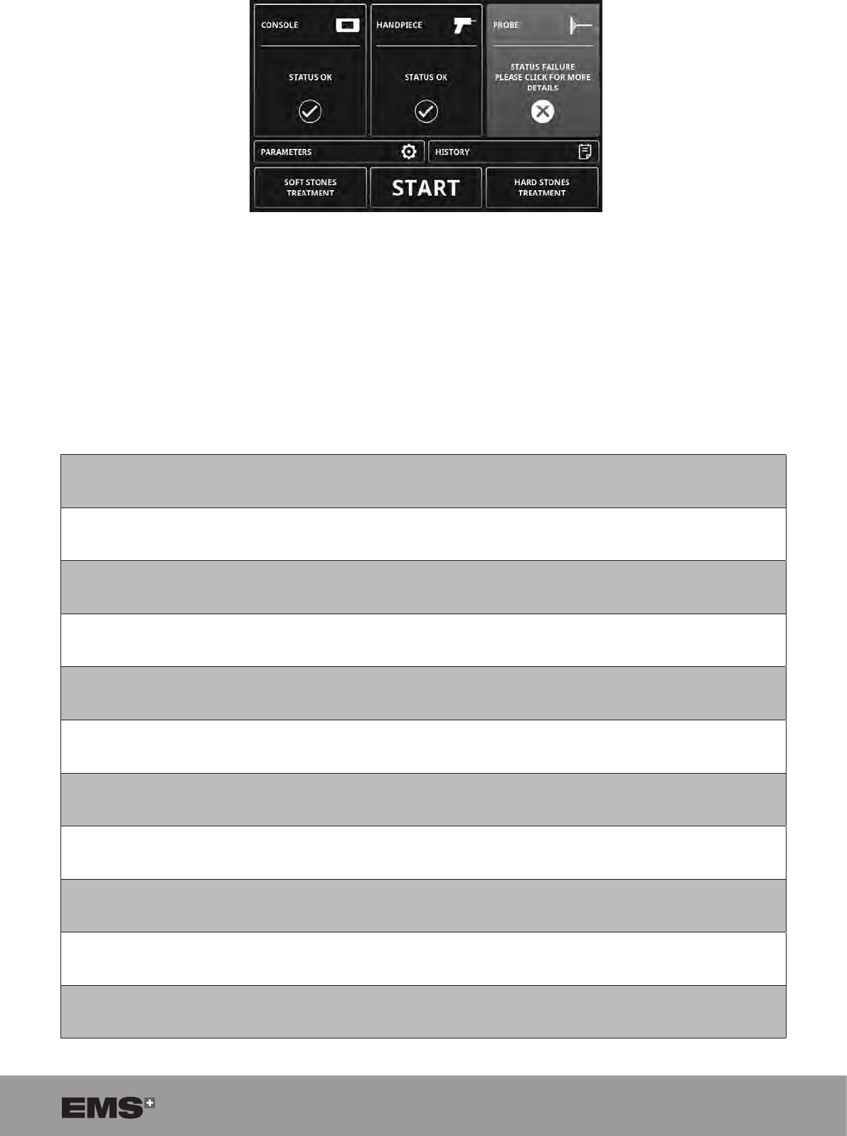
2. Wait until the STAND BY screen appears.
Figure 40
3. The console automatically performs a series of
diagnostic tests.
4. The console displays a green check mark for each
successfully completed diagnostic test.
In case of error messages, refer to the troubleshoo-
ting information provided on the screen or to the
Troubleshooting section.
5. The console is ready for use when all diagnostic tests
have been successfully completed.
The touch screen can be operated when wearing
surgical gloves.
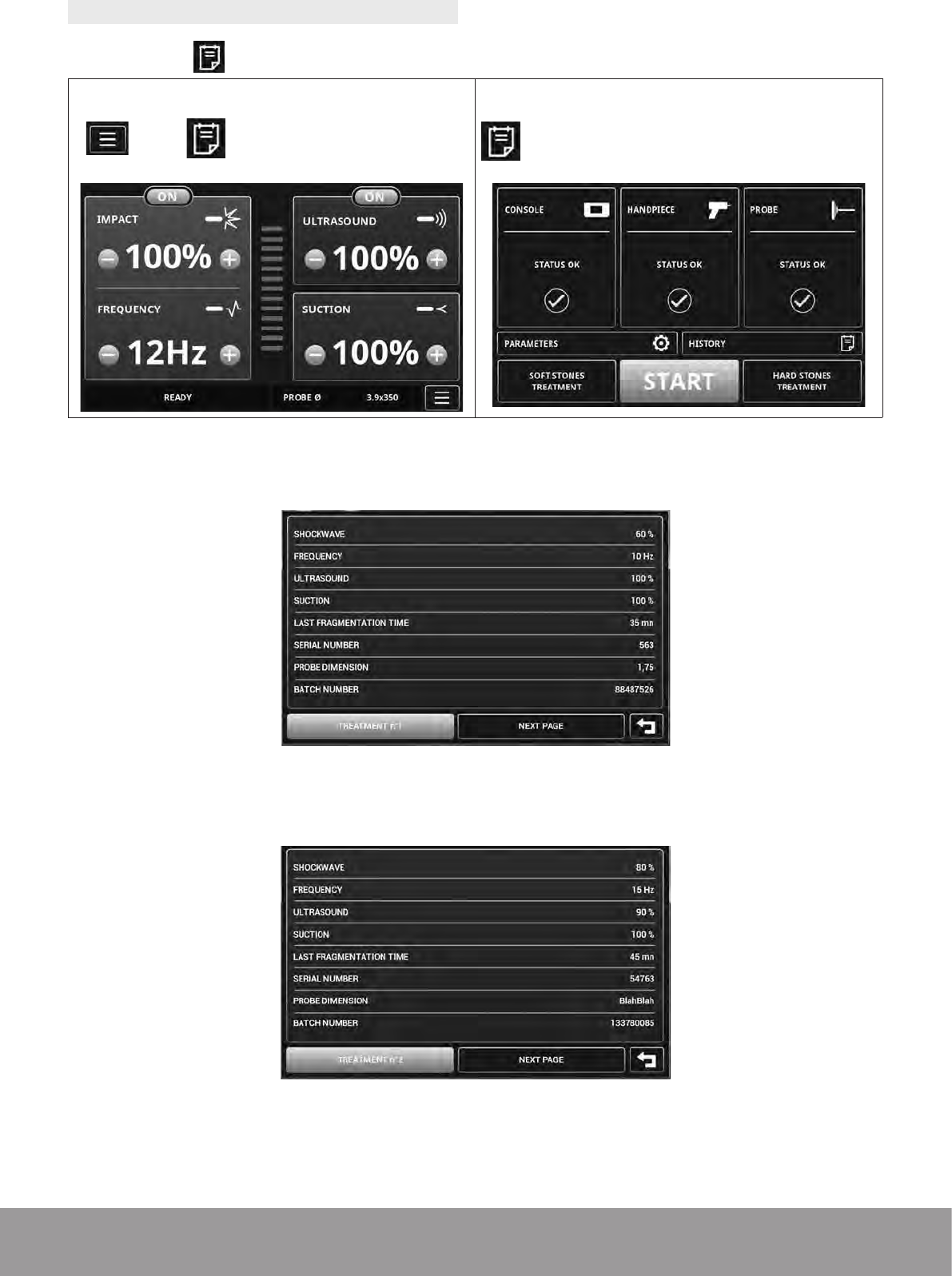
4.2. ADJUSTING THE PARAMETERS
1. To access the PARAMETERS screen from the
STAND BY screen, press PARAMETERS .
Figure 41
2. Congure the parameters as needed.
Figure 42
16 SWISS LITHOCLAST BLAST - FB-610/EN 23-JUNE-2017 / EMS CONFIDENTIAL
Click this pictogram Meaning Action
Log le
download To download the log le and save it on a USB drive.
Several screens will appear.
Choose a
language To select the display language.
Refer to the Setting the Language section.
Brightness Use the and buttons to adjust the display brightness.
Volume Use the and buttons to adjust the volume.
Back To conrm and return to the previous screen.
Table 1
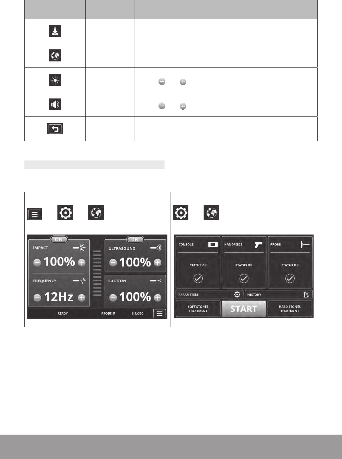
4.2.1. Choosing the Language
1. To access the language selection menu, press:
From the READY screen
ð ð
From the STAND BY screen
ð
Table 2
17
2. Click the language you want to select.
Figure 43
3. To conrm the selected language, click OK.
Figure 44
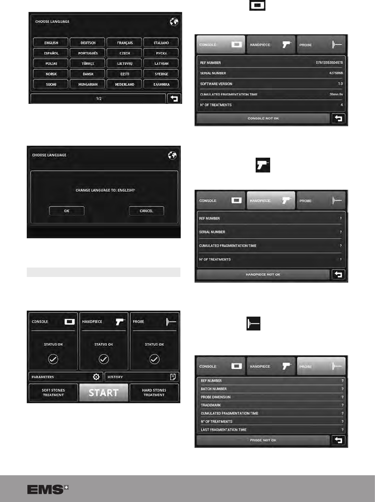
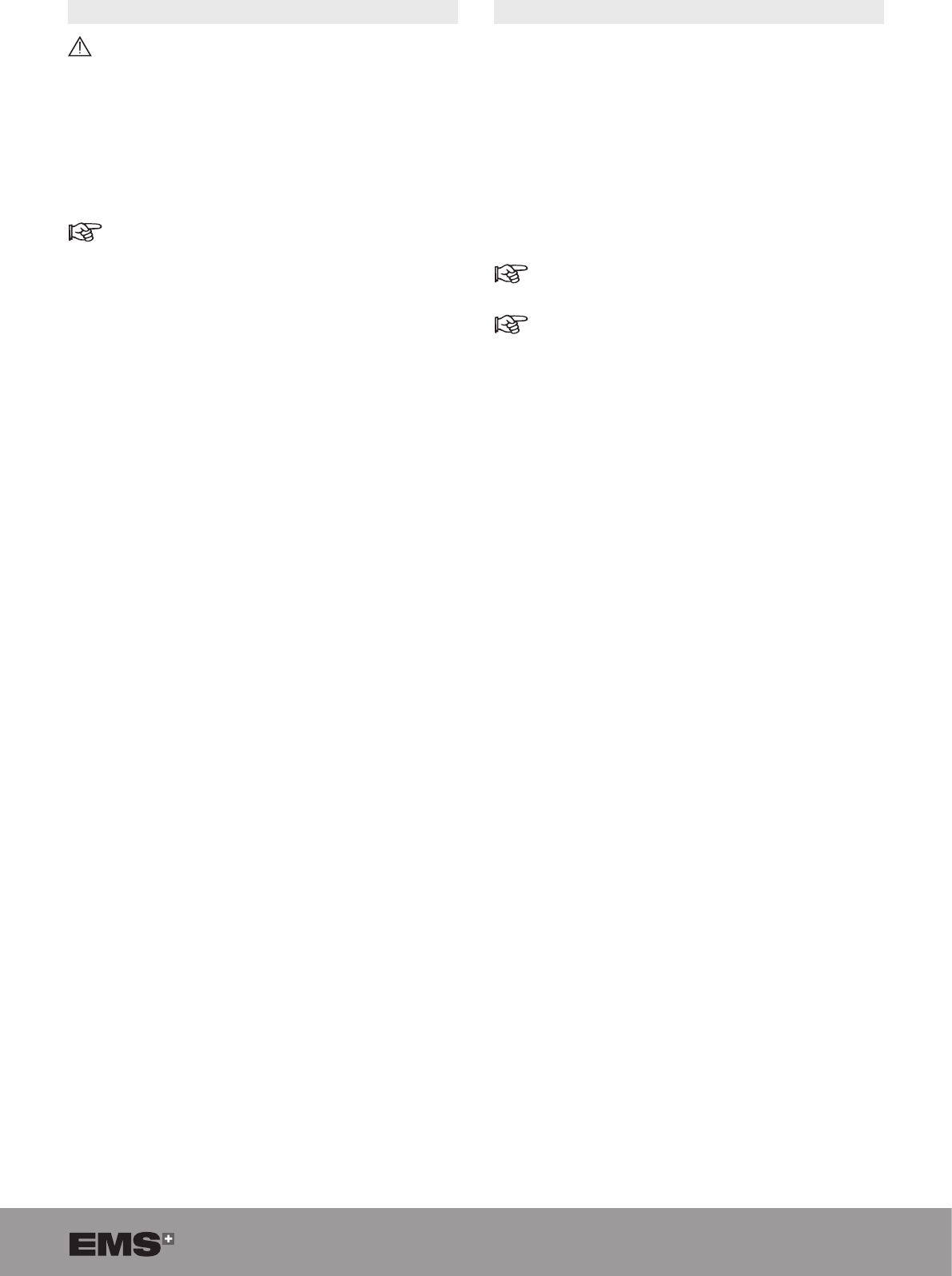
4.3. EQUIPMENT DATA
1. From the STAND BY screen, select the equipment
pictogram to consult its equipment data.
Figure 45
2. Select Console to view the installed software
version number, product serial number, and cumulated
treatment statistics.
Figure 46
3. Select Handpiece to view the handpiece serial
number and cumulated treatment statistics.
Figure 47
4. Select Probe to view the probe reference
number, batch number, probe dimensions, and
cumulated treatment statistics.
Figure 48
18 SWISS LITHOCLAST BLAST - FB-610/EN 23-JUNE-2017 / EMS CONFIDENTIAL
5. TREATMENT
To avoid the risk of electric shock, this product must
only be connected to a mains power supply with
protective earth. No modication shall be made on
this product. The mains power switch of the product
must be accessible at any time.
Do not use the product in surgery after any product
update without rst performing functional tests.
Fragments blocked in the lumen of the probe and
the handpiece may lead to loss of suction and
heating of the probe. If blockage occurs, stop litho-
tripsy. Use the unclogging rod to remove fragments
from the probe and from the handpiece lumen
before continuing.
Figure 49
Do not let the handpiece remain in contact with the
patient during treatment.
During treatment, an auditory information pulse
will be emitted.
This section provides guidance for using the product.
It does not provide detailed instructions for performing
lithotripsy procedures.
5.1. FUNCTIONAL TESTS
If a function or component is not working as
explained below, refer to the Troubleshooting
section.
1. From the STAND BY screen, press the START
button to access the READY screen.
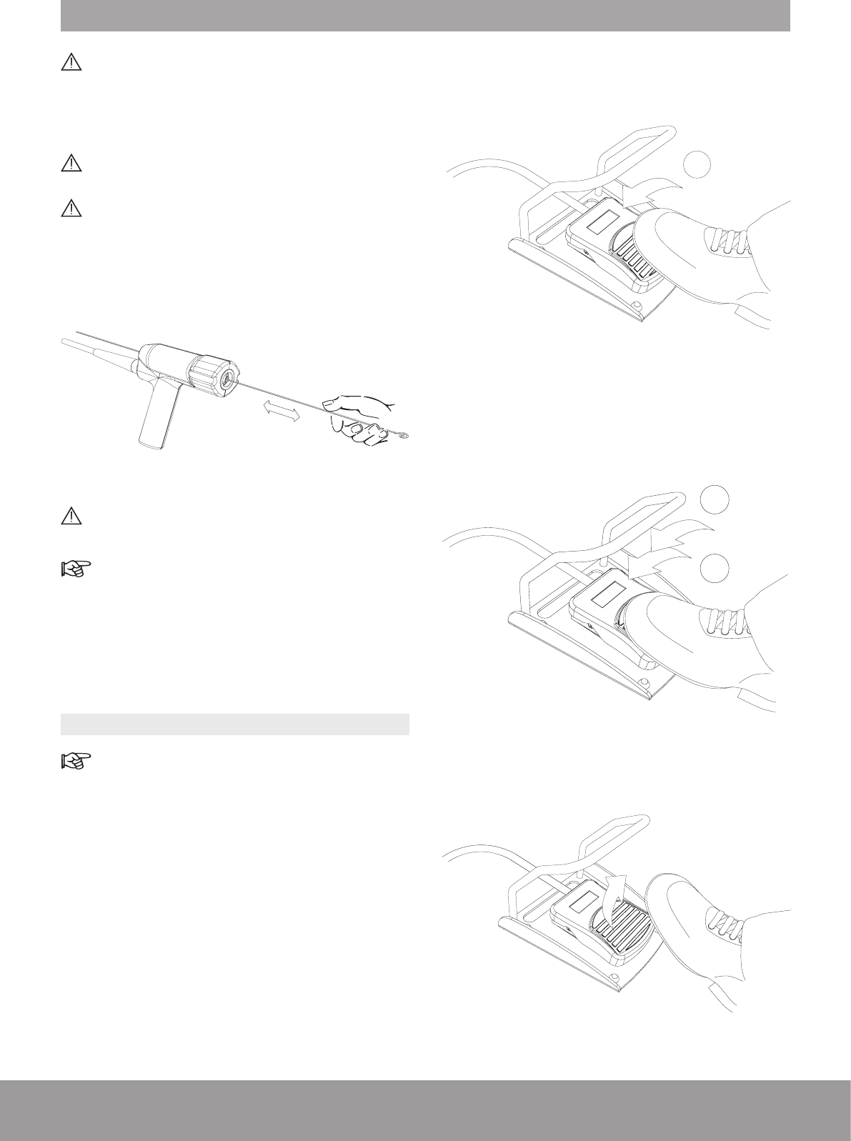
2. Insert the probe into a sterile receptacle of physio-
logical uid.
3. Use the 2-mode foot pedal.
4. Press the pedal halfway (STEP 1) to activate suction
and make sure that suction is working properly (uid
moving through the suction tube).
1
Figure 50
5. Press the pedal completely (STEP 2) to activate both
suction and energies and make sure that the quality
meter is in the green zone and the uid is moving
through the suction tube.
1
2
Figure 51
6. Remove foot from the pedal to stop the functional
test.
Figure 52
19
5.2. PROBE INSERTION
Do not touch the probe during activation.
If a probe breaks distally, use sterile grasping
forceps to remove probe pieces from the urinary
tract.
1. Throughout the entire treatment, keep the probe tips
under endoscopic vision.
To avoid bending the probe, make sure that the
probe and the endoscope are aligned.
The probe tip should be extended 10 - 20 mm
beyond the endoscope tip.
2. Introduce and position the probe inside the endoscope.
3. The probe shall be in contact with the stone.
4. Make sure that the operation is performed with
continuous endoscopic vision.
5.3. TREATMENT SETTINGS
1. The probe is automatically recognized by the
handpiece to congure the console parameters for
each probe type.
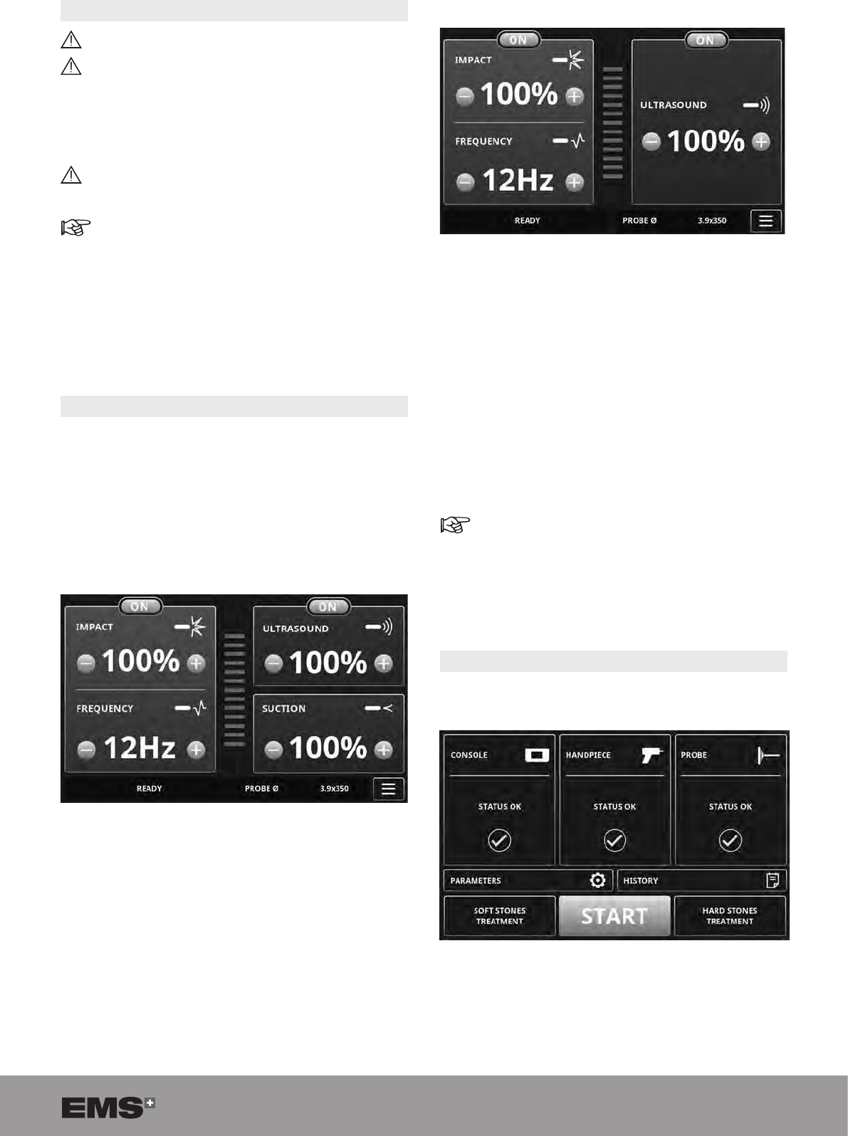
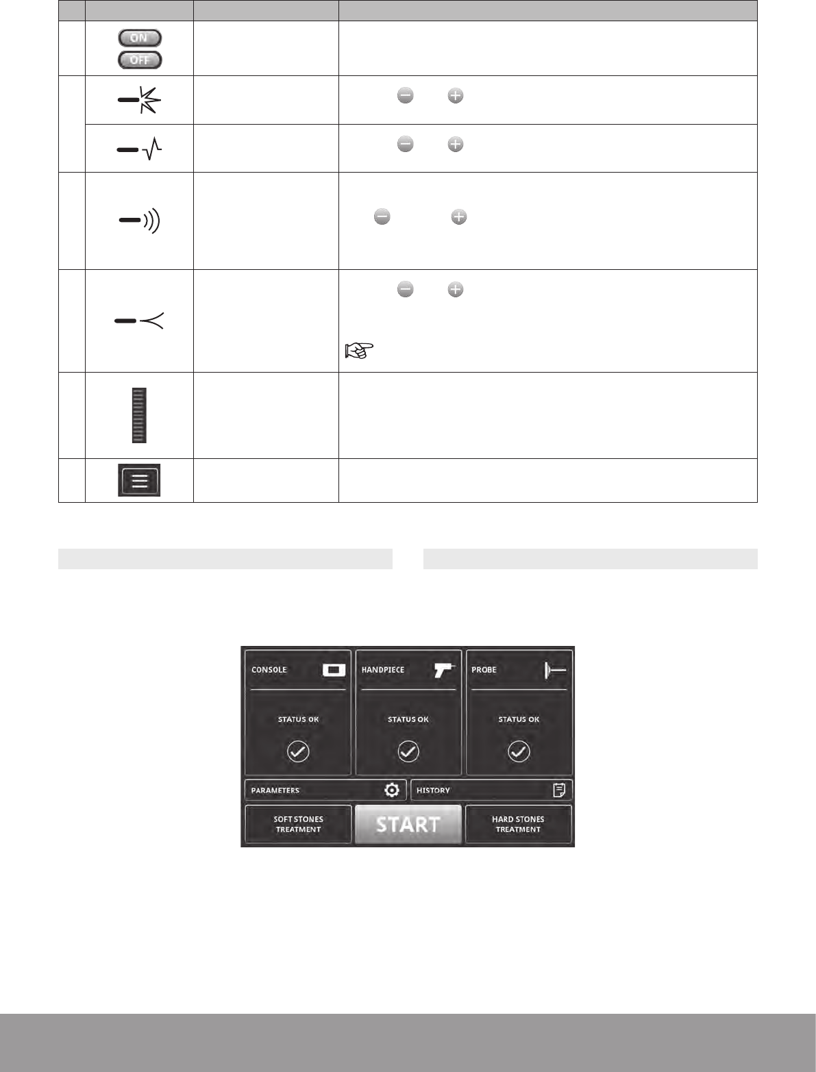
2. The READY screen will display factory settings or the
settings used for the previous treatment.
• For peristaltic pump device
Figure 53
• For pinch valve device
Figure 54
3. All probe and handpiece usage information are
automatically recorded in the console (number of
uses, time of use, etc.).
4. According to the type of treatment, two pre-settings
are available:
• Hard Stones Treatment,
• Soft Stones Treatment.
5. You can also set each parameter manually.
Refer to the following sections:
- Custom Settings,
- Hard Stones Treatment Settings,
- Soft Stones Treatment Settings.
5.3.1. Custom Settings
1. From the STAND BY screen, press the START button.
Figure 55
20 SWISS LITHOCLAST BLAST - FB-610/EN 23-JUNE-2017 / EMS CONFIDENTIAL
2. If required, adjust any settings manually as described in the following table:
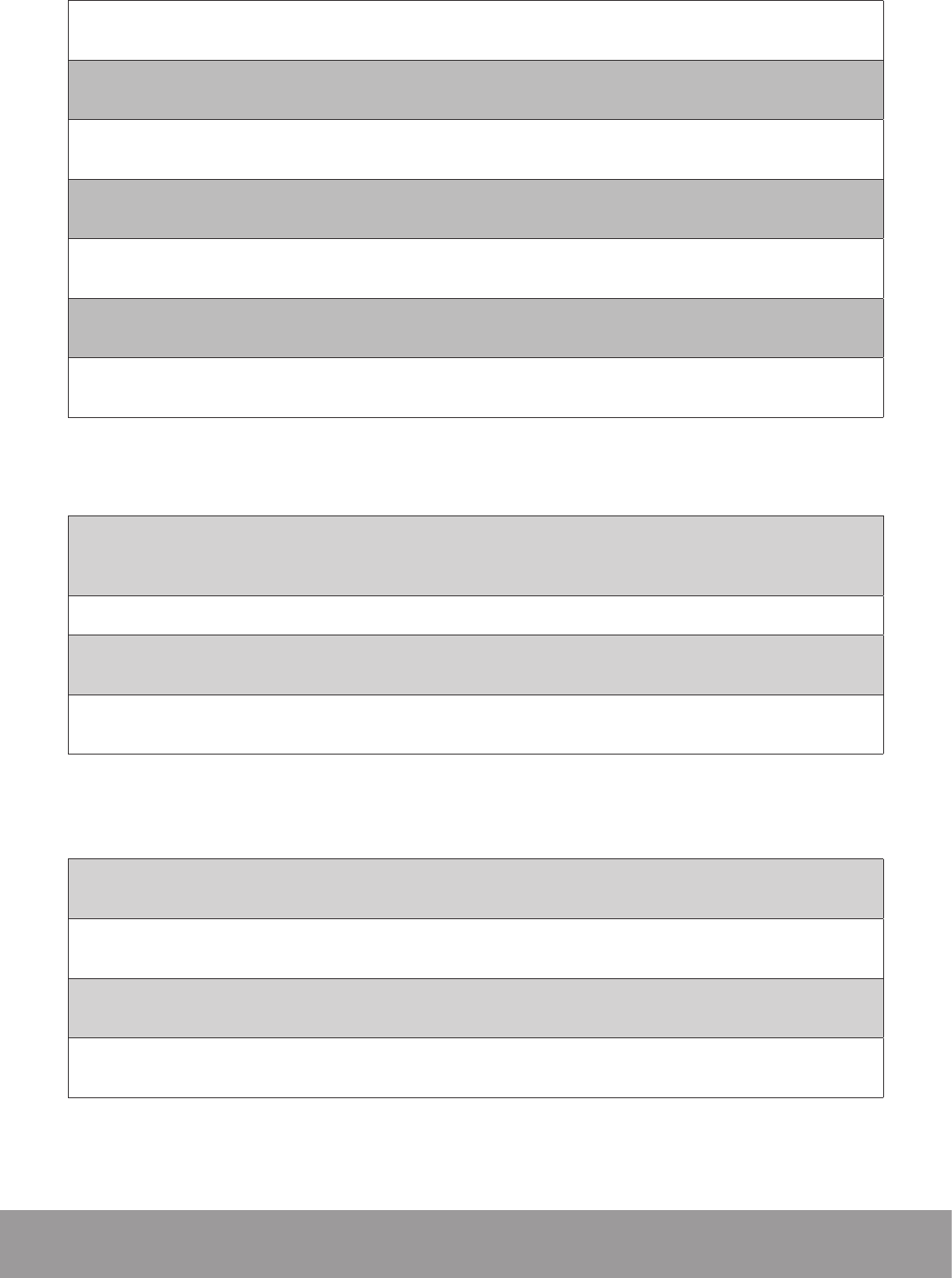
PICTOGRAMS MEANING ACTION
ON/OFF button Use the ON/OFF button to activate or deactivate the functionality in
question.
Impact
Impact power Use the and buttons to adjust the impact power in percent
from 10% to 100% (in 10% increments).
Impact frequency Use the and buttons to adjust the frequency of impact
pulses from 1 Hz to 12 Hz (in 1 Hz increments).
Ultrasound
Ultrasound power Use the and buttons to adjust the ultrasound power from
10% to 100% (in 10% increments).
Suction
Suction ow rate
Use the and buttons to adjust the suction ow rate from
10% to 100% (in 10% increments).
This control is only active for consoles with an integrated
peristaltic pump device.
Treatment Efciency
Indicator
To provide instant visual feedback about the efciency of the
treatment.
• Green: the treatment works properly.
• Orange: the treatment is not efcient.
Menu To return to the STAND BY screen from the READY screen.
Table 3
5.3.2. Hard Stones Treatment Settings
1. To use the hard stones pre-settings, press the HARD
STONES TREATMENT button from the STAND BY
screen.
Figure 56
2. The READY screen will appear and display the hard
stone treatment pre-settings.
3. If required, adjust any settings manually as described
in the table above.
5.3.3. Soft Stones Treatment Settings
1. To use the soft stones pre-settings, press the SOFT
STONES TREATMENT button from the STAND BY
screen.
2. The READY screen will appear and display the soft
stones treatment pre-settings.
3. If required, adjust any settings manually as described
in the table above.
21
5.4. ADAPTING SUCTION FLOW RATE
An excessively high suction level can impair the
endoscopic vision, collapse an organ, or damage
the mucosa.
To adapt the suction ow rate:
• For peristaltic pump device only
1. Use the suction ow rate control as described
in Table 3.
Do not use the roller clamp of the stone catcher to
adapt the suction ow rate.
• For pinch valve device only
1. Adjust the roller clamp of the stone catcher.
2. The pinch valve device default state is closed.
It opens when the pedal is pressed halfway
(STEP 1).
3. The roller clamp on the suction tube controls
the suction ow rate independently of the ow
pressure.
5.5. STARTING TREATMENT
1. Go to the READY screen to start the treatment.
2. Press the pedal halfway (STEP 1) to activate the
suction.
3. Press the pedal completely (STEP 2) to activate both
suction and the energies.
4. Release STEP 2 to deactivate energies.
5. Release STEP 1 to deactivate suction.
Refer to the Functional Tests section for pedal use.
After 1 minute of inactivity, the system automatically
executes a purge and stops cooling the circuit. It
is reactivated when you push the pedal.
22 SWISS LITHOCLAST BLAST - FB-610/EN 23-JUNE-2017 / EMS CONFIDENTIAL
6. POST-TREATMENT PROCEDURE
6.1. COMPLETING TREATMENT
1. Remove the probe from the endoscope.
Figure 57
Do not disconnect the probe and the handpiece
at this stage.
2. Switch off IMPACT and ULTRASOUND from the
READY screen before starting this procedure.
3. Tilt the stone catcher.
Figure 58
4. Press the pedal halfway (STEP 1) for a few seconds
to empty the suction circuit and reduce the level of
water in the stone catcher.
1
Figure 59
To accelerate the emptying procedure, the stone
catcher can be disconnected from the handpiece.
5. The suction tubes must be cleared.
6. Loosen the probe from the handpiece, using one of
the following methods.
Figure 60
23
Figure 61
Figure 62
Wait until the lock icon switches off. The handpiece
cannot be disconnected when the lock icon is on.
6.2. DISCONNECTING THE HANDPIECE
Make sure that the console is still on during this
procedure.
Make sure that the lock icon is off.
Figure 63
1. Pull back the metallic part of the handpiece connector
to disconnect the handpiece.
Figure 64
If the mechanical disconnection of the handpiece
is not possible when the console is switched off,
refer to the Troubleshooting section.
2. Plug the cap on the handpiece connector in the front
panel.
Figure 65
24 SWISS LITHOCLAST BLAST - FB-610/EN 23-JUNE-2017 / EMS CONFIDENTIAL
6.3. RECORDING TREATMENT DATA
1. Select History to view the statistics for the last 5 treatment sessions.
From the READY screen:
ð
From the STAND BY screen:
Table 4
2. Information on the previous treatment sessions will be displayed.
Figure 66
3. Press NEXT PAGE to display more previous treatment data.
Figure 67
25
6.4. DISCONNECTING THE STONE CATCHER
1. Disconnect the stone catcher from the handpiece
and from the uid management system or from your
vacuum system.
Figure 68
6.5. ELIMINATING THE STONE CATCHER
CONTENTS
If the stone fragments are not to be kept for analysis,
dispose of them. Refer to the Product Disposal section.
6.6. CONSERVING THE STONE CATCHER
CONTENTS
If the stone fragments are to be kept for analysis, close
the receptacle with the yellow transport closing cap,
supplied with the stone catcher.
Figure 69
6.7. DISPOSING OF SINGLE-USE COMPONENTS
Dispose of single-use components (probe, Stone Catcher
and fluid management system) in accordance with
hospital protocol.
6.8. SWITCHING OFF THE CONSOLE
Make sure that the lock icon is switched off
before turning off the console.
• Set the mains power switch to 0.
Figure 70
26 SWISS LITHOCLAST BLAST - FB-610/EN 23-JUNE-2017 / EMS CONFIDENTIAL
7. CLEANING, DISINFECTING, AND STERILIZING
7.1. MULTIUSE COMPONENTS
Step A: Preparation at the Point of Use
Safe storage and transportation to the reprocessing
area to avoid any damage to the instrument and
contamination to the environment and the people
involved in the reprocessing process.
After contamination, the sample is allowed to dry
for 1 hour at room temperature.
Step B: Pre-cleaning
For the handpiece, place the protective cap onto
the handpiece connector before cleaning.
Do not remove the protective cap until reproces-
sing is completed.
Figure 71
1. Wipe the product with a damp cloth.
2. Immerse the product in cold tap water for 5 minutes.
3. Use a syringe with 50mL of deionized water to ush
the lumen three times
4. Rinse the product with a water jet pistol (with a
minimum pressure of 3.8 bar) for 30 seconds.
Step C: Cleaning, disinfection and drying process
Step C1. Manual Cleaning, disinfection and drying
process
Cleaning
EMS recommends using Neodisher® MediClean as the
cleaning agent as it has been used for the validation
study.
• Wipe the product with a damp cloth to remove
gross contamination.
• Flush the lumen of the product three times for
5 seconds using a water jet pistol.
• Immerse the product in cold tap water for 5 minutes.
Make sure that all surfaces are moistened.
• Brush all accessible surface with a soft Bristol
nylon brush until all visible residues are removed;
• Immerse the product in 0.5% cleaning solution
for 5 minutes. Make sure that all surfaces are
moistened.
• EMS recommends using Neodisher® MediClean
at 40°C.
• Rinse the product with a water jet pistol for
60 seconds, while paying special attention to each
gap, slit, or hidden surface.
• Rinse the product under cold tap water.
• Dry the product by blowing air for 20 seconds.
Disinfection
The following test devices, materials & machines have
been used for the validation study:
• Disinfection agent: Cidex® OPA.
• Immerge the product in a disinfectant solution for
10 minutes. Care that all surfaces are moistened.
• EMS recommended to use Cidex OPA at 20°C.
• Rinse the product with a water jet pistol for
60 seconds, while paying special attention to each
gap, slit, or hidden surface.
• Rinse the product under cold tap water.
Disinfection must be performed no later than 1 hour
after the cleaning phase.
Sterilization must be performed after disinfection.
Drying
Dry the outside of the instrument with a lint-free towel.
Dry the lumen of the products with ltered compressed
air (max. pressure 3 bar).
The instrument must never be heated >138°C.
27
Step C2. Automated Cleaning, disinfection and drying
process
Automated Cleaning, disinfection and drying validation
has been performed using a Miele 7735CD washing
machine, and the cleaning agent Neodisher® Mediclean.
EMS recommends using Neodisher® Mediclean for their
products.
For this step, a Washer/Disinfector machine must have
suitable baskets to hold small, fragile products and rinsing
connections for the attachment to product lumina.
The program of the Washer/Disinfector machine shall be
able to perform the following steps.
Place the instrument in a suitable rack and start the
program. The Vario TD programs have been shown to
be effective:
• 2 min pre-washing with cold water (<40°C). Drain;
• 5 min washing with 0.5% detergent at 55°C. Drain;
• 3 min neutralising with warm water (>40°C). Drain;
• 2 min intermediate rinsing with warm water
(>40°C). Drain.
Special instructions of the manufacturer for the Washer/
Disinfector must be followed.
Disinfection (if required by national laws)
Automated Thermal Disinfection in a Washer/Disinfector
taking into consideration national requirements in regards
to A0-Value (see EN 15883) e.g. 93°C for 3 minutes.
A machine cleaning and disinfection method should
always be used for cleaning/disinfection because of the
increased effectiveness of this method.
Sterilization must be performed after disinfection.
Drying
Drying of outside of instrument through drying cycle of the
Washer/Disinfector. If needed, additional manual drying
can be performed using a lint-free towel and filtered
compressed air (max. pressure 3 bar).
The instrument must never be heated >138°C.
Step D. Functional Testing, Maintenance
If stains are still visible on the product after cleaning/
disinfection, the entire cleaning/disinfection procedure
must be repeated. Products with visible damage, chips/
akes, corrosion or bent out of shape must be disposed
of (no further use is permissible).
Step E. Packaging for sterilization
Prior to sterilization, the products must be placed in a
suitable sterilization container or sterilization packaging:
Compliant with EN ISO 11607 or EN 868.
Step F. Sterilization
Sterilization of instruments by applying a fractionated
pre-vacuum process (according ISO 13060 and
ISO 17665) taking into consideration the respective
country requirements.
Do not exceed the maximum number of sterilization
cycles, please refer to the instruction manual.
Step F1. Prevacuum sterilization
Parameters for the pre-vacuum cycle:
• 3 prevacuum phases
• Sterilization temperature of 132°C for 3 minutes
• Drying time: minimum 20 min
• Do not exceed a sterilization temperature of 138°C
and a holding time of 20 min.
Step K. Storage
Storage of sterilized instruments in a dry, clean and dust
free environment at modest temperatures of 5°C to 40°C.
[Doigts] Handpiece must have the lumen positionned
verticaly in the sterilizer
28 SWISS LITHOCLAST BLAST - FB-610/EN 23-JUNE-2017 / EMS CONFIDENTIAL
7.2. CONSOLE, PEDAL, AND CART
1. Turn off the console.
Figure 72
2. Disconnect the power supply connector before
cleaning.
Figure 73
3. Remove the protective bag from the pedal, if appli-
cable.
4. Plug the cap on the handpiece connector in the front
panel
Figure 74
5. Use a cleaning wipe with proven efcacy (e.g., enzol
2%) to clean the surfaces.
The housing of the console is not waterproof.
6. To disinfect use 70% isopropyl alcohol or other
EPA-recognized surface disinfectant. Be sure to
carefully follow the instructions provided by the disin-
fection solution manufacturer.
29
8. PRODUCT MAINTENANCE
Should legal provisions in your country specify mainte-
nance intervals, these must be observed. The console
and handpiece may need to be returned for periodic
servicing.
For the spare parts described below, please refer to the
order form or contact your EMS authorized service center.
8.1. COOLING LIQUID CIRCUIT MAINTENANCE
The cooling liquid and the water lter must be
replaced every year. Regular maintenance is
required for product to function properly.
This procedure is applicable for pump and pinch
valve version.
1. Empty the cooling liquid circuit.
Refer to the Product Storage and Shipping section
for instructions on emptying the cooling liquid
circuit.
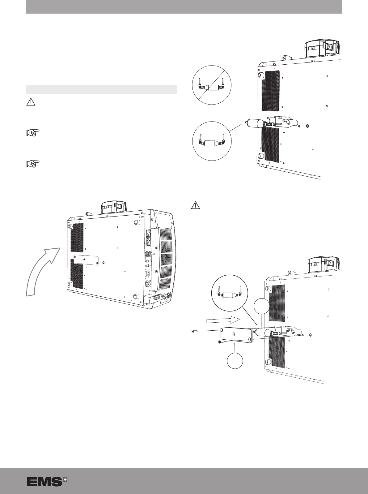
2. Place the console at on its side.
Figure 75
3. Use the Torx tool size 20 to remove the water lter
cover (A).
4. Push the colored ring with your left hand and simulta-
neously pull the plug to remove the lter tube.
5. Replace the water lter.
Figure 76
Connect the tubes to the corresponding color.
The grey ring is on the left and the green ring is
on the right.
6. Re-install the water lter (B) and cover (A).
B
A
Figure 77
30 SWISS LITHOCLAST BLAST - FB-610/EN 23-JUNE-2017 / EMS CONFIDENTIAL
7. Replace the console on a at surface.
8. Refill the cooling system. Refer to the Filling the
Cooling System section.
8.2. REPLACING FUSES
1. Disconnect the power cord at the rear of the console.
Figure 78
2. Remove the fuse drawer located in the power socket.
Figure 79
3. Replace defective fuses with the fuse type specied
on the identication plate at the rear of the console.
4. Re-insert the fuse drawer.
5. If the fuses fail again, please contact your EMS autho-
rized service center.
8.3. DOWNLOADING LOGFILE
An EMS service center may request this procedure.
1. Plug the USB key provided by EMS at the rear of the
console.
2. From the STANDBY screen, select PARAMETERS
3. Press LOGFILE DOWNLOAD.
4. Follow the procedure displayed on the screen.
31
9. PRODUCT STORAGE AND SHIPPING
Do not tilt or invert the console without rst having
emptied the cooling liquid circuit.
Always empty the cooling liquid circuit before
longterm storage (2 weeks or more) or shipping to
avoid damage to the console.
Storage and transport conditions are specied in
the Technical Data section.
9.1. EMPTYING THE COOLING LIQUID CIRCUIT
1. Unplug all cables at the rear of the console.
2. Place the console on a at, stable surface.
3. To remove the air vent plug, push the grey ring with
your left hand and simultaneously pull the plug.
Figure 80
4. Make sure that the metal locking device is in the
down position.
Figure 81
5. Put the draining tube in a receptacle that is more than
600 ml in volume.
Figure 82
6. Connect the draining tube (supplied with the product)
to the outlet.
Figure 83
7. Tilt the console until the connector is in contact with
the at, stable surface to fully empty the cooling liquid
circuit.
Figure 84
32 SWISS LITHOCLAST BLAST - FB-610/EN 23-JUNE-2017 / EMS CONFIDENTIAL
8. Unlock the metal locking part to disconnect the
draining tube.
Figure 85
9. Re-insert the air vent plug.
9.2. SHIPPING THE PRODUCT
Before shipping the product, follow the instructions
provided in the Cleaning, Disinfecting and Steril-
izing section.
To avoid damage, pack the product and all acces-
sories in the original packaging. Make sure to insert
the air vent plug prior to packing and shipping the
product.
33
10. PRODUCT DISPOSAL
The product must not be discarded in
domestic household waste.
Should you wish to denitively dispose
of the product, please comply with the
applicable regulations in your country.
Keep the original packaging until the product is to be
disposed of permanently.
Waste Electrical and Electronic Equipment belonging
to customers located in the European Union may be
shipped to EMS for recycling in accordance with the
WEEE regulations. The costs of recycling, exclusive of
shipping fees, are covered by EMS.
11. EMS TECHNICAL SUPPORT
Please contact your EMS authorized service center for
any product servicing or repairs. You must complete the
appropriate EMS form in order to be issued a Return
Material Agreement (RMA) number.
EMS declines responsibility for the safety of the product
and declares the warranty null and void if service or
repair is carried out by an unauthorized third party or if
non-genuine spare parts are used.
It is mandatory to return your product in its original
packaging. By following these packaging guidelines,
your product shall be protected against damage during
shipment. To protect the personnel of the EMS authorized
service center and for safety reasons during transport and
shipment, all products and accessories returned to the
factory for repair or servicing must be cleaned, disinfected
and sterilized in accordance with the instruction manual.
Repair can be refused for products or accessories
received in a contaminated condition.
When sending your product directly to the EMS autho-
rized service center, please include the name of the
distributor to simplify processing.
34 SWISS LITHOCLAST BLAST - FB-610/EN 23-JUNE-2017 / EMS CONFIDENTIAL
12. TROUBLESHOOTING
Ensure that the product and the accessories have
been used in accordance with the conditions
specied by EMS.
Only contact an EMS service center if none of the
following instructions works.
To improve our quality of service, please provide the
following information:
• Product reference number,
• Software revision,
• Batch number/serial number,
• Service history of the product (e.g., previous issues
or repairs).
12.1. MANUAL HANDPIECE UNLOCKING
Only use the manual handpiece unlocking
procedure when disconnection has failed.
Refer to the Disconnecting the Handpiece sec-
tion.
1. Turn off the console.
2. Keep the console in its at position.
3. Insert a needle (2mm diameter) until you reach the
stop.
4. Push the needle to the right to unlock the handpiece.
The handpiece is unlocked.
1
2
Figure 86
5. Remove the handpiece.
12.2. WEAK SUCTION
1. Make sure that the stone catcher tube is correctly
inserted in the peristaltic pump/pinch valve.
2. Make sure that the stone catcher roller clamp is not
closed.
3. Check that no clogging occurs in the handpiece or
probe.
4. Make sure that there are no leaks in the suction circuit.
5. Replace the liquid collection pouch if it is full.
6. Make sure that the stone catcher cover is fully
tightened up to the stop.
7. Make sure that the stone catcher is correctly tightened
on the handpiece.
• For Pinch Valve Device
1. Make sure that the pinch valve opens when the pedal
is pressed down.
• For Peristaltic Pump Device
1. Increase the suction from the READY screen.
2. Open the cover of the pump to check that the rollers
on the head of the pump turn.
3. Make sure that there are no leaks in the collection
system.
12.3. PROBE NOT COMPATIBLE WITH THE
ENDOSCOPE
1. Refer to the Probe Compatibility Table section to
check the diameter and/or length of the probes with
respect to the dimensions of the endoscope.
2. Check the physical integrity of the probe.
3. Replace the probe.
12.4. DISPLAYED ERROR MESSAGES
In case of a malfunction or an operating error, the
faulty component is automatically highlighted in
the STAND BY screen.
In case of critical error, the system stops and
automatically reverts to the STAND BY screen.
35
Figure 87
1. Press the highlighted faulty component and follow
the interactive menu to identify the exact origin of
the error.
2. Follow the recommended action that is displayed.
3. If the solutions proposed fail to solve the problem,
please contact your EMS authorized service center.
Do not, in any case, return a product before trouble-
shooting of the error has been performed.
4. The following table provides more detailed information
about failures: error number and associated error
messages.
• Console
E001 - The cooling pump is not detected and handpiece cooling might not be available. Please restart device.
Please contact your EMS authorized service center if the error persists.
E002 - The cooling valve is not detected and handpiece cooling might not be available. Please restart device.
Please contact your EMS authorized service center if the error persists.
E008 - Conguration les of the console are corrupted and informations might be incorrect. Please contact your
EMS authorized service center.
E009 - Console internal communication error. Please restart device. Please contact your EMS authorized service
center if the error persists.
E010 - Pedal not detected. Please verify that the connector of the pedal is connected to the console. Please
contact your EMS authorized service center if the error persists.
E016 - No suction system has been detected. Please restart device or contact your EMS authorized service center
if the error persists.
E017 - Two suction systems seem to be connected. Please restart device or contact your EMS authorized service
center if the problem persists.
E018 - The console temperature is high. Treatment is still possible but verify the console is placed in a correctly
ventilated place
E019 - The console temperature is too high. System needs to cool down. Please keep it powered while temperature
returns to safe level.
E020 - Console internal communication error. System trying to recover. Please restart device or contact your EMS
authorized service center if the error persists.
E024 - Console internal communication error. Please restart device or contact your EMS authorized service center
if the error persists.
36 SWISS LITHOCLAST BLAST - FB-610/EN 23-JUNE-2017 / EMS CONFIDENTIAL
E025 - Console temperature error. Please wait for the console to cool down. Please contact your EMS authorized
service center if the error persists.
E026 - Shockwave module critical error. Please restart the device. Please contact your EMS authorized service
center if the error persists.
E027 - Ultrasound module critical error. Please restart the device. Please contact your EMS authorized service
center if the error persists.
E031 - The console temperature sensor was not detected. Please restart the device. Please contact your EMS
authorized service center if the error persists.
E032 - Fan was not detected. Please restart the device. Please contact your EMS authorized service center if
the error persists.
E034 - Handpiece lock not detected. Please restart the device. Please contact your EMS authorized service
center if the error persists.
E038 - The console temperature sensor was not detected. Please restart the device. Please contact your EMS
authorized service center if the error persists.
Table 5
• Handpiece
E003 - The handpiece temperature is rising and could be harmful. Please let the system cool down. Verify cooling
tank water level and handpiece cord sealing. Please check that after handpiece disconnection that the handpiece
cooling circuit is dry. Please contact your EMS authorized service center if the error persists.
E004 - The handpiece temperature is high. Treatment is still possible but verify cooling tank level.
E005 - Handpiece not detected. Please verify that the handpiece is connected to the console. Replace the
handpiece if the error persists.
E037 - The handpiece temperature sensor was not detected. Please restart the device. Please contact your EMS
authorized service center if the error persists.
Table 6
• Probe
E011 - Probe has exceeded the usage limit. The probe use policy is validated for a maximum number of usage
cycles. Continue treatment at your own responsibility.
E012 - Probe not detected. Please check that the probe is correctly installed on the handpiece. Please contact
your EMS authorized service center if the error persists.
E013 - Unknown probe. Please verify that the probe is a valid one or undamaged. Please contact your EMS
authorized service center if the error persists.
E035 - Probe settings can’t be automatically loaded. Please change probe. Please contact your EMS authorized
service center if the error persists.
Table 7
37
13. FORMER ELECTROMAGNETIC COMPATIBILITY
The SWISS LITHOCLAST® TRILOGY should not be used adjacent to or stacked with another SWISS LITHOCLAST®
TRILOGY. If adjacent or stacked use is necessary, the SWISS LITHOCLAST® TRILOGY should be observed to verify
normal operation in the conguration in which it will be used.
Guidance and manufacturer’s declaration – electromagnetic emissions
The SWISS LITHOCLAST® TRILOGY is intended for use in the electromagnetic environment specied below. The
customer or the user of the SWISS LITHOCLAST® TRILOGY should ensure that it is used in such an environment.
Emissions Test Compliance Electromagnetic Environment – Guidance
RF emissions
CISPR 11
Group 1 The SWISS LITHOCLAST® TRILOGY uses RF energy only for its
internal function. Therefore, its RF emissions are very low and are not
likely to cause any interference in nearby electronic equipment.
RF emissions
CISPR 11
Class B The SWISS LITHOCLAST® TRILOGY is suitable for use in all establish-
ments, including residential establishments and those directly connected
to the public low-voltage power supply network that supplies buildings
used for domestic purposes.
Harmonics emissions
IEC 61000-3-2
Class A
Voltage uctuations /
icker emissions
IEC 61000-3-3
Complies
Table 8
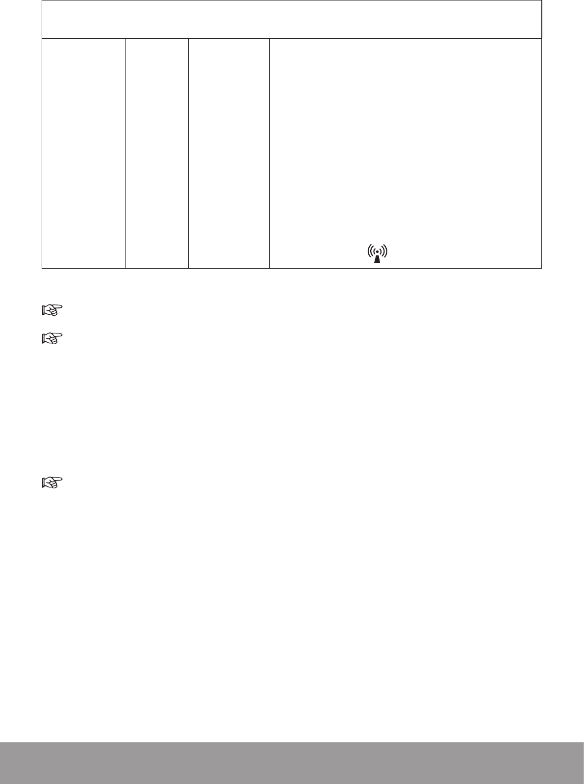
Guidance and Manufacturer’s Declaration – Electromagnetic Immunity
The SWISS LITHOCLAST® TRILOGY is intended for use in the electromagnetic environment specied below. The
customer or the user of the SWISS LITHOCLAST® TRILOGY should ensure that it is used in such an environment.
Immunity Test IEC 60601
Test Level Compliance level Electromagnetic Environment –
Guidance
Electrostatic
discharge (ESD)
IEC 61000-4-2
± 6 kV contact
± 8 kV air
± 6 kV contact
± 8 kV air
Floors should be wood, concrete or ceramic
tile. If floors are covered with synthetic
material, the relative humidity should be at
least 30%.
Electrical fast
transient / burst
IEC 61000-4-4
± 2 kV for power supply
lines
±1 kV for input/output lines
± 2 kV for power
supply lines
Not applicable
Mains power quality should be that of a typical
commercial or hospital environment.
Surge
IEC 61000-4-5
± 1 kV line(s) to line(s)
± 2 kV line(s) to earth
± 1 kV line(s) to line(s)
± 2 kV line(s) to earth
Mains power quality should be that of a typical
commercial or hospital environment.
Power frequency
(50/60 Hz)
magnetic eld
IEC 61000-4-8
3 A/m 3 A/m Power frequency magnetic elds should be
at levels characteristic of a typical location in
a typical commercial or hospital environment.
Voltage dips,
short inter-
ruptions and
voltage varia-
tions on power
supply input
lines
IEC 61000-4-11
<5% UT (>95% dip in UT)
for 0.5 cycle
40% UT (60% dip in UT)
for 5 cycles
70% UT (30% dip in UT)
for 25 cycles
<5% UT (>95% dip in UT)
for 5 s
<5% UT (>95% dip in
UT) for 0.5 cycle
40% UT (60% dip in
UT) for 5 cycles
70% UT (30% dip in
UT) for 25 cycles
<5% UT (>95% dip in
UT) for 5 s
Mains power quality should be that of a typical
commercial or hospital environment. If the
user of the SWISS LITHOCLAST® TRILOGY
requires continued operation during power
mains interruptions, it is recommended that
the SWISS LITHOCLAST® TRILOGY be
powered from an uninterruptible power supply
or a battery.
Table 9
38 SWISS LITHOCLAST BLAST - FB-610/EN 23-JUNE-2017 / EMS CONFIDENTIAL
Portable and mobile RF communications equipment should be used no closer to any part of the SWISS LITHOCLAST®
TRILOGY, including cables, than the recommended separation distance calculated from the equation applicable to
the frequency of the transmitter.
Conducted RF
IEC 61000-4-6
Radiated RF
IEC 61000-4-3
3 Vrms
150 kHz –
80 MHz
3 V/m
80 MHz –
2.5 GHz
10 Vrms
10 V/m
Recommended separation distance
d = 0.35 √P
d = 0.35 √P 80 MHz – 800 MHz
d = 0.7 √P 800 MHz – 2.5 GHz
where P is the maximum output power rating of the transmitter
in watts (W) according to the transmitter manufacturer and d is
the recommended separation distance in meters (m).
Field strengths from xed RF transmitters, as determined by an
electromagnetic site survey,a should be less than the compliance
level in each frequency range.b
Interference may occur in the vicinity of equipment marked with
the following symbol:
Table 10
At 80 MHz and 800 MHz, the higher frequency range applies.
These guidelines may not apply to all situations. Electromagnetic propagation is affected by absorption and
reection from structures, objects and people.
a Field strengths from xed transmitters, such as base stations for radio (cellular/cordless) telephones and land
mobile radios, amateur radios, AM and FM radio broadcast and TV broadcast cannot be predicted theoretically with
accuracy. To assess the electromagnetic environment due to xed RF transmitters, an electromagnetic site survey
should be considered. If the measured eld strength in the location in which the SWISS LITHOCLAST® TRILOGY is
used exceeds the applicable RF compliance level above, the SWISS LITHOCLAST® TRILOGY should be observed
to verify normal operation. If abnormal performance is observed, additional measures may be necessary, such as
re-orienting or relocating the SWISS LITHOCLAST® TRILOGY.
b Over the frequency range 150 kHz to 80 MHz, eld strengths should be less than 10 V/m.
UT is the A/C mains voltage prior to application of the test level.
39
Recommended separation distances between portable and mobile RF communications equipment and the
SWISS LITHOCLAST® TRILOGY
The SWISS LITHOCLAST® TRILOGY is intended for use in an electromagnetic environment in which radiated RF
disturbances are controlled. The customer or the user of the SWISS LITHOCLAST® TRILOGY can help prevent
electromagnetic interference by maintaining a minimum distance between portable and mobile RF communications
equipment (transmitters) and the SWISS LITHOCLAST® TRILOGY as recommended below, according to the maximum
output power of the communications equipment.
Rated maximum
output power of
transmitter [W]
Separation distance according to frequency of transmitter [m]
150 kHz to 80 MHz
d = 0.35 √P
80 MHz to 800 MHz
d = 0.35 √P
800 MHz to 2.5 GHz
d = 0.7 √P
0.01 0.04 m 0.04 m 0.07 m
0.1 0.13 m 0.13 m 0.22 m
1 0.4 m 0.4 m 0.7 m
10 1.3 m 1.3 m 2.2 m
100 4 m 4 m 7 m
Table 11
For transmitters rated at a maximum output power not listed above, the recommended separation distance (d) in
meters (m) can be estimated using the equation applicable to the frequency of the transmitter, where power (P) is the
maximum output power rating of the transmitter in watts (W) according to the transmitter manufacturer.
At 80 MHz and 800 MHz, the separation distance for the higher frequency range applies.
These guidelines may not apply to all situations.
Electromagnetic propagation is affected by absorption and reection from structures, objects and people.
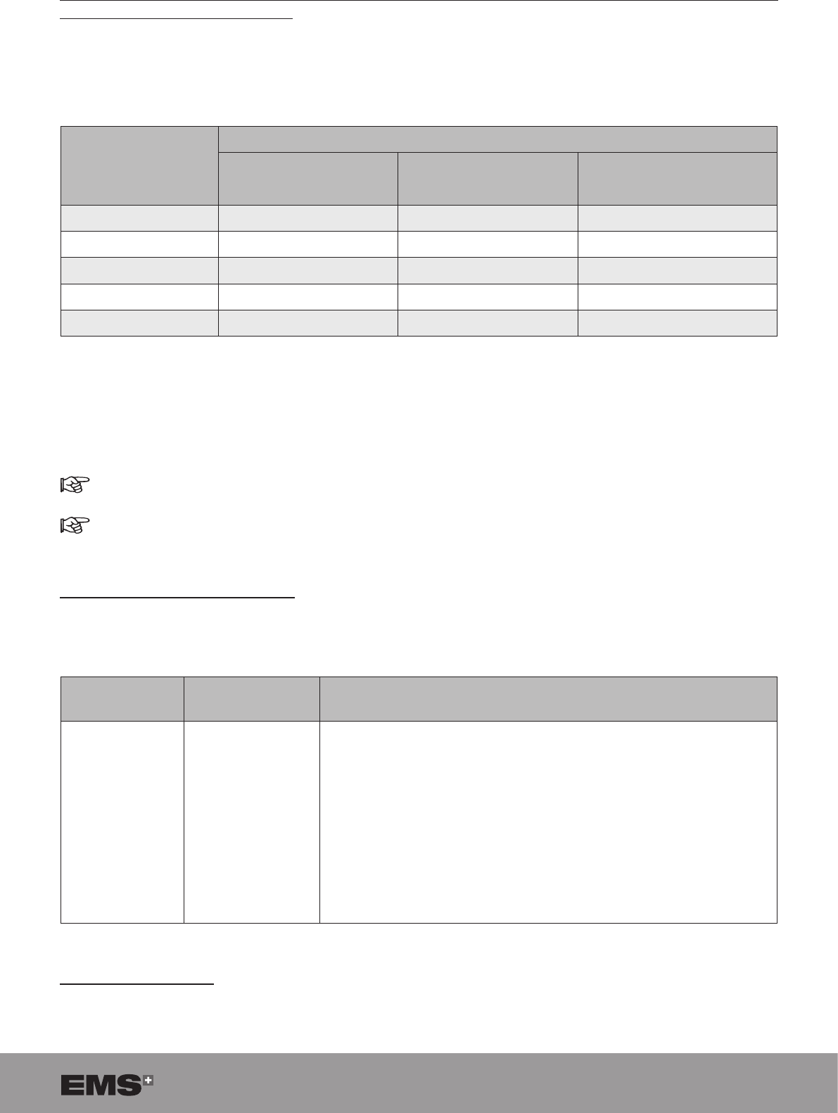
Compliant cables and accessories
The use of accessories and cables other than those specied or sold by EMS as replacement parts may result in
increased emissions or decreased immunity of this product.
Cables and
accessories Maximum length Complies with
Handpiece cord
Pedal
2.9 m
2.9 m
CISPR 11 Class B / Group 1: RF electromagnetic disturbance
IEC 61000-4-2 Electrostatic discharge (ESD)
IEC 61000-4-3 Electromagnetic elds radiated by radio-frequencies
IEC 61000-4-4 Electric fast transient / burst
IEC 61000-4-5 Surge
IEC 61000-4-6 Disturbances induced by radio-frequency elds
IEC 61000-4-8 Power frequency magnetic eld (50/60 Hz)
IEC 61000-4-11 Voltage dips, short interruptions and voltage variations
Table 12
Essential performance
The SWISS LITHOCLAST® TRILOGY has neither life sustaining functions nor diagnostic of life supporting functions.
40 SWISS LITHOCLAST BLAST - FB-610/EN 23-JUNE-2017 / EMS CONFIDENTIAL
14. NEW ELECTROMAGNETIC COMPATIBILITY
Electromagnetic compatibility according to IEC 60601-1-2:2014
Guidance and manufacturer’s declaration – electromagnetic emissions
The Swiss LithoClast® Trilogy is intended for use in the electromagnetic environment specied below. The
customer or the user of the Swiss LithoClast® Trilogy should assure that it is used in such an environment.
EMISSIONS TEST COMPLIANCE ELECTROMAGNETIC ENVIRONMENT - GUIDANCE
RF emissions
CISPR 11 Group 1 The Swiss LithoClast® Trilogy uses RF energy only for its internal
function. Therefore, its RF emissions are very low and are not
likely to cause any interference in nearby electronic equipment.
RF emissions
CISPR 11 Class A
The emissions characteristics of the Swiss LithoClast® Trilogy
make it suitable for use in hospitals only.
Harmonic emissions
IEC 61000-3-2
Not applicable
Voltage uctuation / icker
emissions
IEC 61000-3-3
Not applicable
Table 13
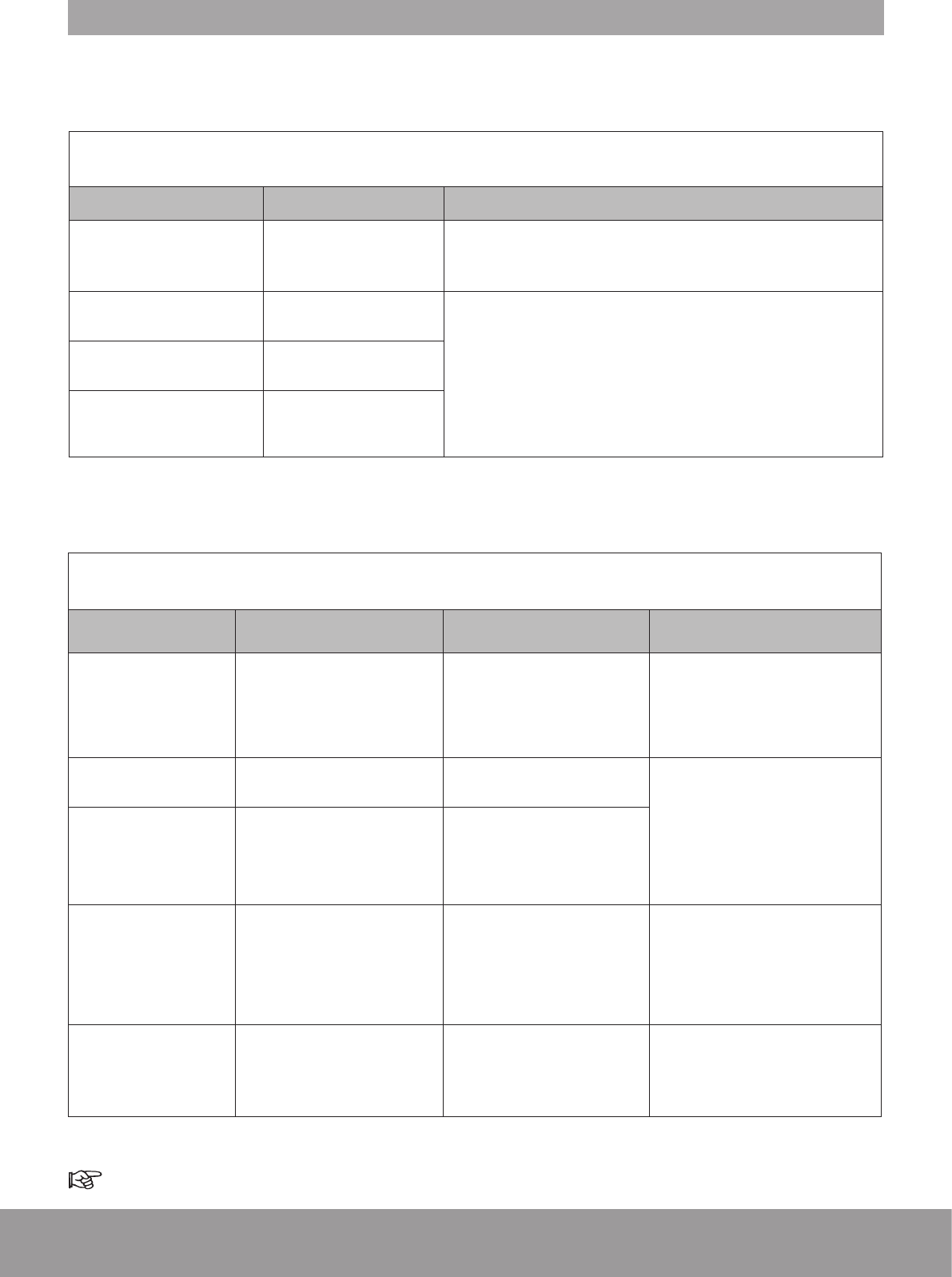
Guidance and manufacturer’s declaration – electromagnetic immunity
The Swiss LithoClast® Trilogy is intended for use in the electromagnetic environment specied below. The
customer or the user of the Swiss LithoClast® Trilogy should assure that it is used in such an environment.
IMMUNITY TEST IEC 60601
TEST LEVEL COMPLIANCE LEVEL ELECTROMAGNETIC
ENVIRONMENT - GUIDANCE
Electrostatic discharge
(ESD)
IEC 61000-4-2
± 8 kV contact
± 15 kV air
± 8 kV contact
± 15 kV air
Floors should be wood, concrete
or ceramic tile. If oors are
covered with synthetic material,
the relative humidity should be at
least 30%.
Radiated RF
IEC 61000-4-3
3 V/m
80 MHz to 2.7 GHz
10 V/m
80 MHz to 2.7 GHz Portable and mobile RF communi-
cations equipment should be used
no closer than 30 cm to any part
of the Swiss LithoClast® Trilogy,
including cables.
Proximity elds from RF
wireless communica-
tions equipment
IEC 61000-4-3
See next table See next table
Conducted RF
IEC 61000-4-6
3 V rms
150 kHz to 80 MHz
6 V rms
in ISM and amateur radio
bands
3 V rms
150 kHz to 80 MHz
6 V rms
in ISM and amateur radio
bands
Power frequency
(50/60 Hz) magnetic
eld
IEC 61000-4-8
30 A/m 30 A/m
Power frequency magnetic elds
should be at levels character-
istic of a typical location in a
typical commercial or hospital
environment.
Table 14
UT is the A/C mains voltage prior to application of the test level.
41
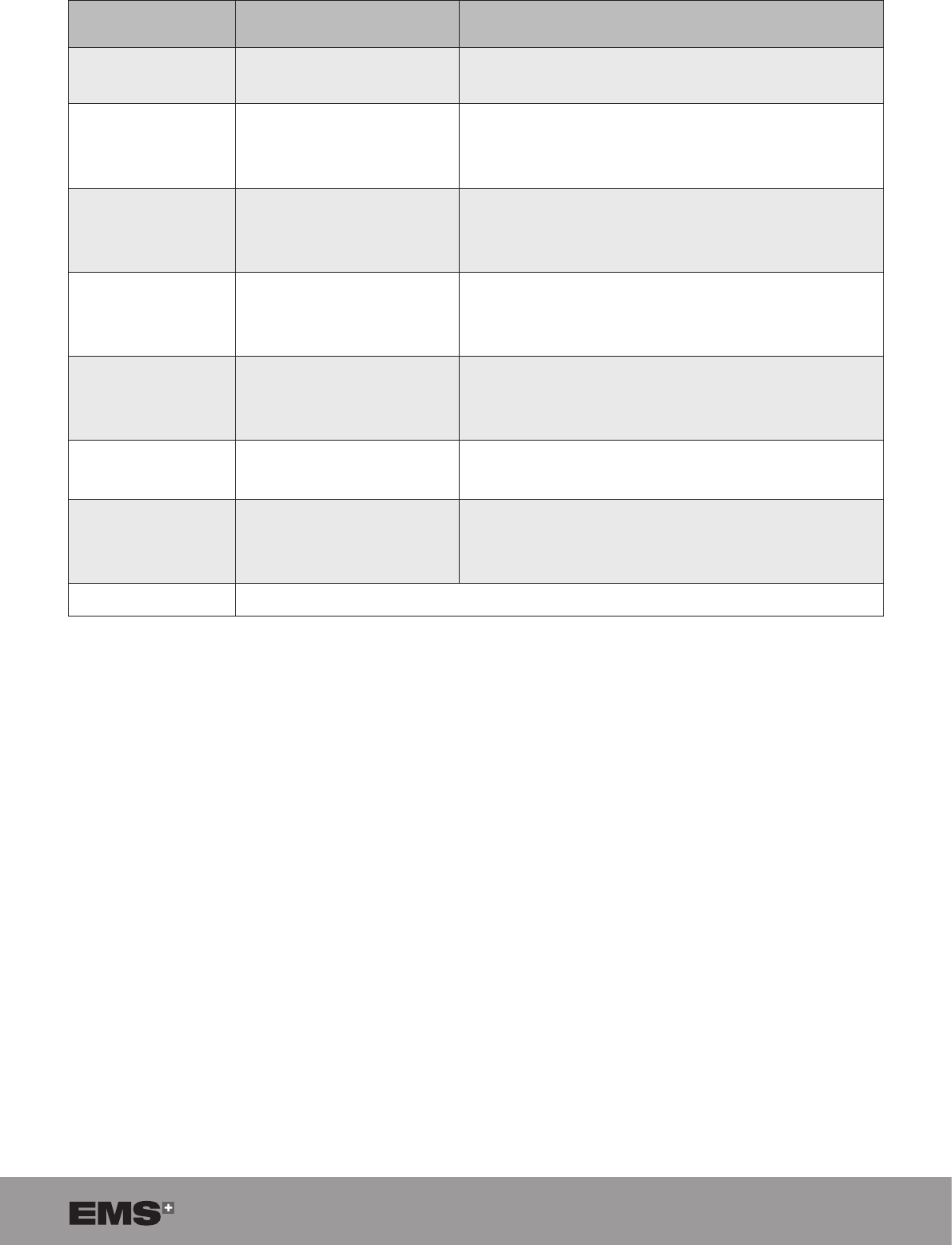
Proximity elds from RF wireless communications equipment
TEST FREQUENCY
(MHZ) MODULATION IEC 60601
TEST LEVEL
385 Pulse modulation a
18 Hz 27 V/m
450
FM
± 5 kHz deviation
1 kHz sine
28 V/m
710
754
780
Pulse modulation a
217 Hz 9 V/m
810
870
930
Pulse modulation a
18 Hz 28 V/m
1720
1845
1970
Pulse modulation a
217 Hz 28 V/m
2450 Pulse modulation a
217 Hz 28 V/m
5240
5500
5785
Pulse modulation a
217 Hz 9 V/m
a50% duty cycle square wave signal
Table 15

42 SWISS LITHOCLAST BLAST - FB-610/EN 23-JUNE-2017 / EMS CONFIDENTIAL
15. TECHNICAL DATA
MANUFACTURER E.M.S. Electro Medical Systems S.A., CH-1260 Nyon, Switzerland
MODEL SWISS LITHOCLAST® TRILOGY
POWER SUPPLY 100 – 240 VAC, 50 – 60 Hz, 500 VA
EN 60601-1 CLASSIFICATION System: EN 60601-1: Class I
Probe: EN 60601-1: Class I BF
MDD 93/42 EEC
CLASSIFICATION Class IIb: device, handpiece
Class IIa: probes
Class I: uid management system, pedal, torque wrench, cart
Class Is: Stone catcher
IEC 60529 IP
CLASSIFICATION Console (IP21)
Handpiece (IPX8)
Pedal (IPX8)
PRIMARY FUSE 6.3A, T (slow), 250 VAC (=T6.3A250V)
Dimensions: Ø5 X 20 mm
CONSOLE Weight: 13.5 kg
Dimensions: height – 135 mm, width – 360 mm, depth – 420 mm
OPERATING CONDITIONS Temperature: +10°C to +30°C
Relative humidity: 30% to 75%
Atmospheric pressure: 700 hPa to 1060 hPa
Max. altitude: 3000 m
TRANSPORT AND STORAGE
CONDITIONS Temperature: 1°C to +40°C
Relative humidity: 10% to 90%
Atmospheric pressure: 70 kPa to 106 kPa
PRODUCT USAGE PERIOD Console lifetime: 7 years
Sterile accessories shelf-life: 2 years
Handpiece lifetime: 2 years or 100 usage cycles
Torque wrench lifetime: 3 years, or 6000 clicks/300 sterilizations
COOLING LIQUID Demineralised water
MAXIMUM
TRANSPORTABLE
WEIGTH ON THE CART
40kg
OUTPUT Power (Ultrasound) 70 Watt
OUTPUT POWER (Shock) 80 Watt
Probes, Stone catcher, Fluid Management system:
Temperature: -29°C to +38°C
Relative humidity: 10% to 90%
Handpiece
Temperature: -29°C to +38°C
Relative humidity: max 85%
Console and its accessories
Temperature: +5°C to +38°C
Relative humidity: max 85%
43
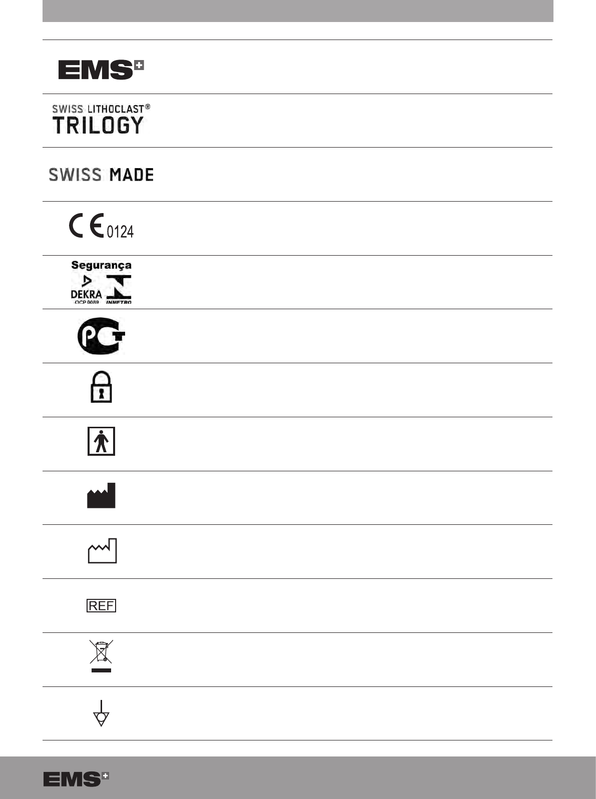
16. SYMBOLS
Manufacturer logo
Product name
Origin of the product
CE symbol refers to directive 93/42/EC, including EN 60601-1 and EN 60601-1-2
DEKRA INMETRO identication for products in conformance with Brazilian electrical
standards
GOST R marking for products in conformance with Russian standards
Lock icon
Applied part, type BF
Manufacturer
Year of manufacture
Catalogue number
Disposal of Old Electrical & Electronic Equipment (Applicable in the European Union
and other European countries with separate collection systems)
Equipotential plug
44 SWISS LITHOCLAST BLAST - FB-610/EN 23-JUNE-2017 / EMS CONFIDENTIAL
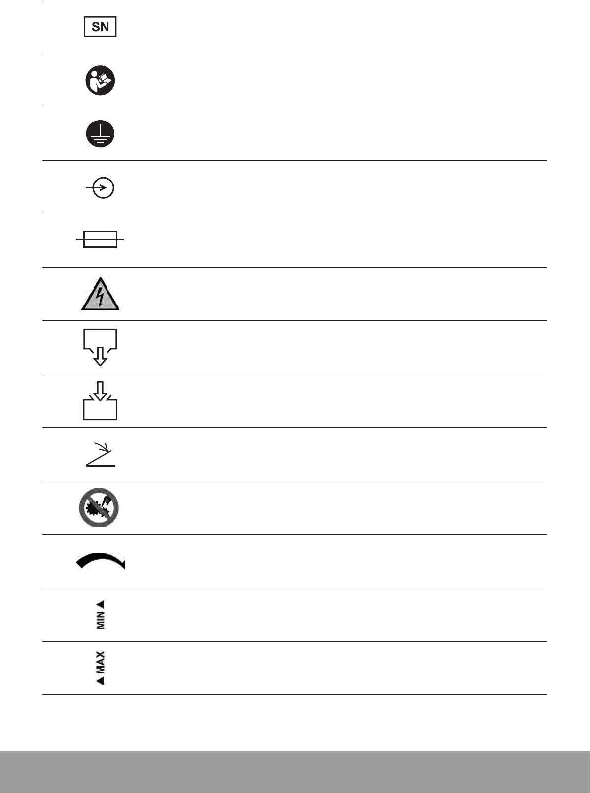
Serial number
Refer to the instruction manual
Device requiring protective earth
Input
Fuse
Risk of electric shock
Emptying
Filling
Foot pedal connection
Do not allow ngers to come into contact with moving parts
Flow direction
Minimum tank level indicator
Maximum tank level indicator
45
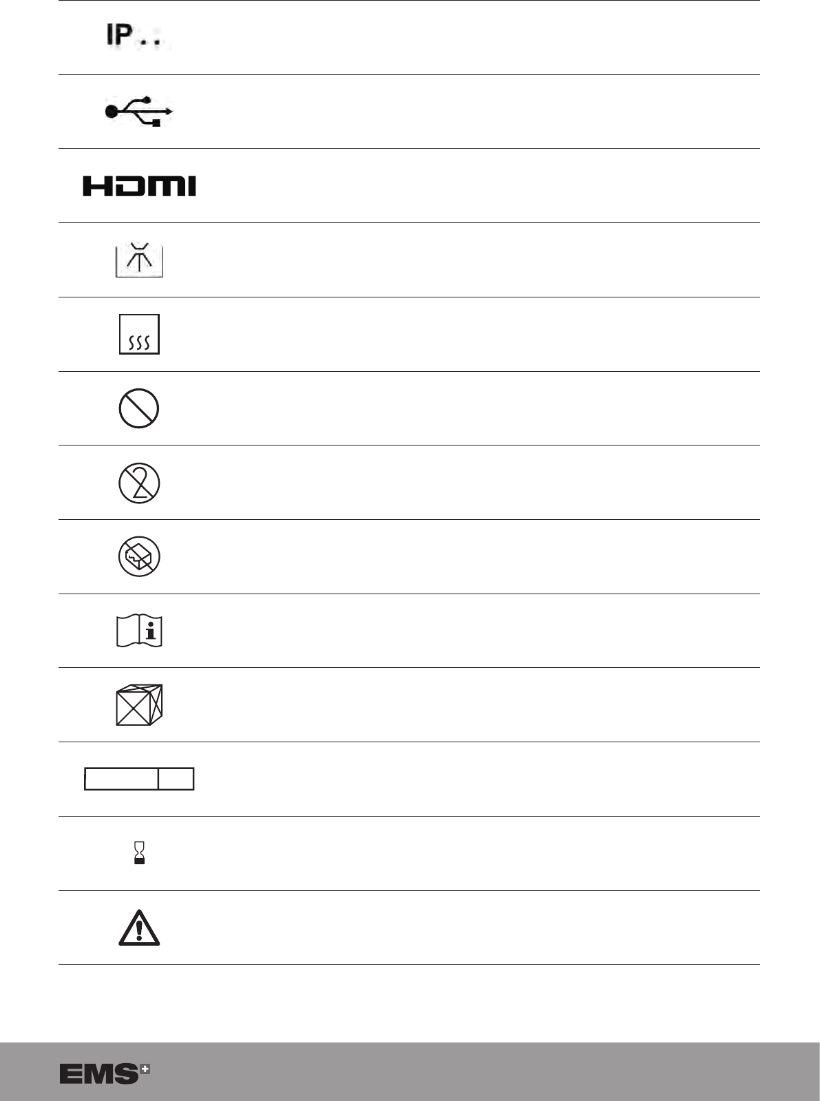
Degree of protection against water permeability
USB connector
HDMI connector
Thermal disinfection
135°C
Sterilizable at up to 135°C in the autoclave
2
STERILIZE
Do not re-sterilize
Do not re-use
Do not use if package is damaged
Refer to instruction manual
Content
STERILE EO
Sterilized using ethylene oxide
Use by
Danger
Table 16
46 SWISS LITHOCLAST BLAST - FB-610/EN 23-JUNE-2017 / EMS CONFIDENTIAL
17. APPENDIX
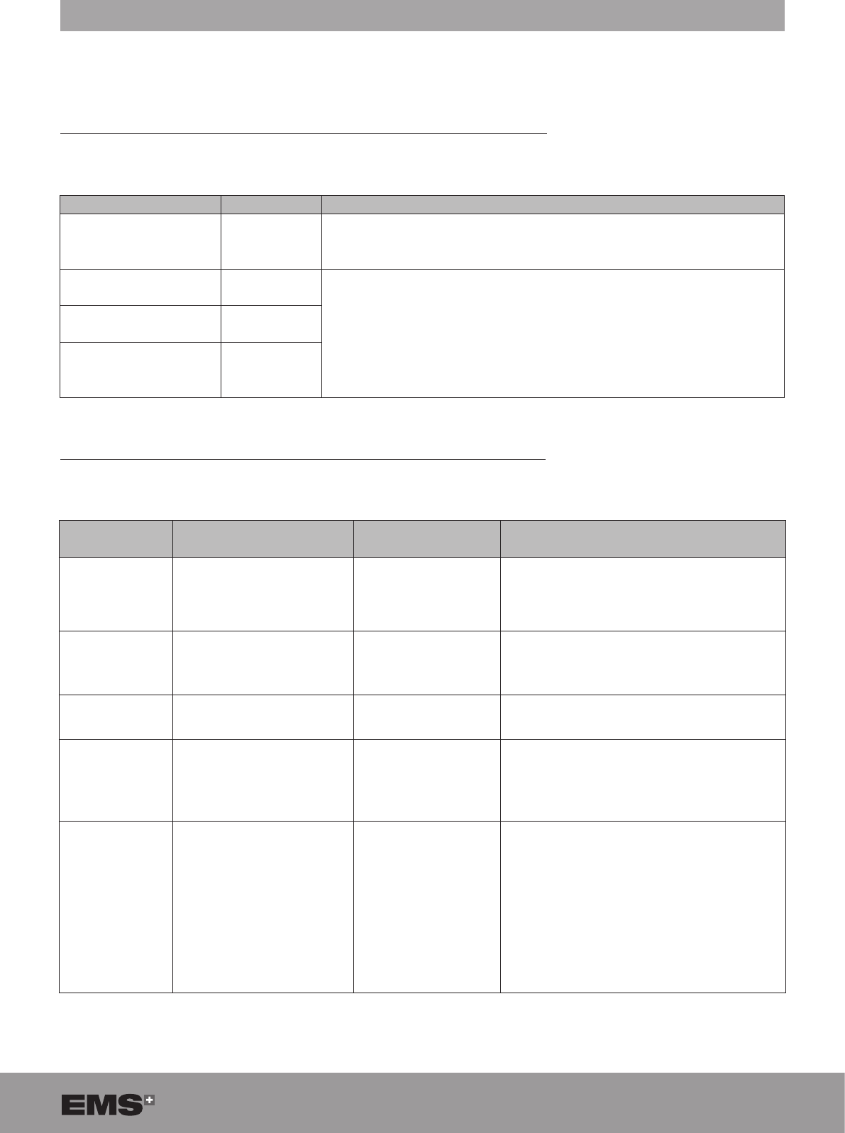
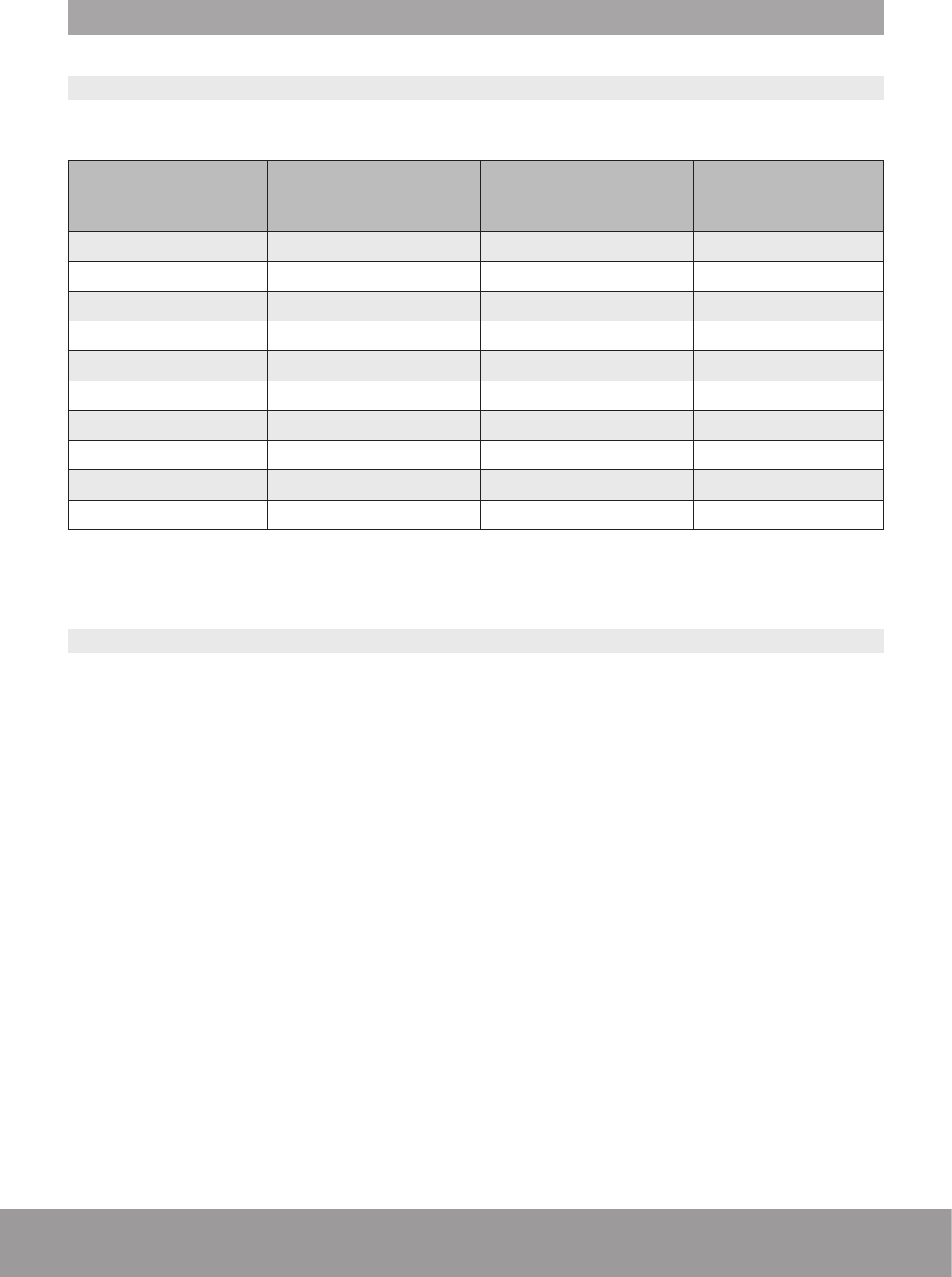
17.1. PROBE COMPATIBILITY TABLE
Different probe sizes are available to allow effective treatment with the most popular endoscopic systems for percu-
taneous nephroscopy, rigid and semi-rigid ureteroscopy and cystoscopy:
PROBE DIAMETER
AND LENGTH MINIMUM ENDOSCOPE
WORKING CHANNEL
SIZE
MAXIMUM ENDOSCOPE
WORKING CHANNEL
LENGTH
TAG RING COLOR
Ø 1.1 mm x 425 mm 4 Fr 400 mm RED
Ø 1.1 mm x 520 mm 4 Fr 500 mm RED
Ø 1.1 mm x 625 mm 4 Fr 600 mm RED
Ø 1.5 mm x 425 mm 5 Fr 400 mm ORANGE
Ø 1.5 mm x 520 mm 5 Fr 500 mm ORANGE
Ø 1.9 mm x 341 mm 6 Fr 320 mm YELLOW
Ø 3.4 mm x 340 mm 10.5 Fr 320 mm GREEN
Ø 3.4 mm x 445 mm 10.5 Fr 420 mm GREEN
Ø 3.9 mm x 350 mm 12 Fr 330 mm BLUE
Ø 3.9 mm x 440 mm 12 Fr 420 mm BLUE
Table 17
* US and suction not available
17.2. FCC AND IC
This device complies with Part 15 of the FCC Rules. Operation is subject to the following two conditions:
(1) this device may not cause harmful interference, and
(2) this device must accept any interference received, including interference that may cause undesired operation.
Any changes or modications not expressly approved by Electro Medical Systems for compliance could void the user’s
authority to operate this equipment.
This equipment has been tested and found to comply with the limits for a Class A digital device, pursuant to Part 15
of the FCC Rules. These limits are designed to provide reasonable protection against harmful interference when the
equipment is operated in a commercial environment. This equipment generates, uses, and can radiate radio frequency
energy and, if not installed and used in accordance with the instruction manual, may cause harmful interference to
radio communications. Operation of this equipment in a residential area is likely to cause harmful interference in which
case the user will be required to correct the interference at his own expense.
FCC RF exposure statement:
Important note: This device complies with FCC and Industry Canada radiation exposure limits set forth for general
population. This device must not be co-located or operating in conjunction with any other antenna or transmitter.
IC Statements:
This device complies with Industry Canada license-exempt RSS standard(s). Operation is subject to the following
two conditions:
(1) this device may not cause interference, and
(2) this device must accept any interference, including interference that may cause undesired operation of the device.
Under Industry Canada regulations, the radio transmitter(s) in this device may only operate using an antenna of a
type and maximum (or lesser) gain approved for the transmitter by Industry Canada. To reduce potential radio inter-
ference to other users, the antenna type and its gain should be so chosen that the equivalent isotropically radiated
power (e.i.r.p.) is not more than that necessary for successful communication.

47
Le présent appareil est conforme aux CNR d'Industrie Canada applicables aux appareils radio exempts de licence.
L'exploitation est autorisée aux deux conditions suivantes :
(1) l'appareil ne doit pas produire de brouillage, et
(2) l'utilisateur de l'appareil doit accepter tout brouillage radioélectrique subi, même si le brouillage est
susceptible d'en compromettre le fonctionnement.
Conformément à la réglementation d'Industrie Canada, le présent émetteur radio peut fonctionner avec une
antenne d'un type et d'un gain maximal (ou inférieur) approuvé pour l'émetteur par Industrie Canada.
Dans le but de réduire les risques de brouillage radioélectrique à l'intention des autres utilisateurs, il faut choisir
le type d'antenne et son gain de sorte que la puissance isotrope rayonnée équivalente (p.i.r.e.) ne dépasse pas
l'intensité nécessaire à l'établissement d'une communication satisfaisante.
Le présent appareil est conforme aux niveaux limites d’exigences d’exposition RF pour la
population globale définies par Industrie Canada. L’appareil ne doit pas être installé à
proximité ou être utilisé en conjonction avec une autre antenne ou un autre émetteur.
Remarque importante : Cet appareil est conforme aux limites d'exposition aux radiations définies par la FCC et par
Industrie Canada pour la population générale. Cet appareil ne doit pas être placé ou fonctionner à côté d'une autre
antenne ou émetteur.
Déclaration d'exposition aux ondes radioélectriques de la FCC

EMS Electro Medical Systems SA EMS worldwide ofces (medical)
EMS-SWISSQUALITY.COM
SUISSE
Ch. de la Vuarpillière 31
1260 Nyon
SWITZERLAND
Tel. +41 22 99 44 700
Fax +41 22 99 44 701
e-mail: welcome@ems-ch.com
Manufacturer
EMS Electro Medical Systems SA
Ch. de la Vuarpillière 31
1260 Nyon
SWITZERLAND
FRANCE
EMS France Sarl
23, Av. Louis Bréguet
Immeuble Santos Dumont, Bâtiment D
F-78140 Vélizy Villacoublay
Tél. +33 1 34 58 03 80
Fax +33 1 34 58 03 90
e-mail: info@ems-france.fr
ITALY
EMS Italia S.r.l
Via Faravelli 5
I-20149 Milano
Tel. +39 02 3453 8075
Fax +39 02 3453 1724
e-mail: medical@ems-italia.it
USA/CANADA
EMS Corporation
11886 Greenville Avenue #120
Dallas, TX 75243, USA
Tel. +1 972 690 83 82
Fax +1 972 690 89 81
e-mail: info@ems-na.com
GERMANY
EMS Medical GmbH
Schatzbogen 86
D-81829 München
Tel. +49 89 43 57 29 990
Fax +49 89 43 57 29 90 66
e-mail: info@ems-medical.de
SPAIN
EMS Electro Medical Systems España SL
Bernardino Obregón 14 bis
E-28012 Madrid
Tlf. +34 91 528 99 89
Fax +34 91 539 34 89
e-mail: administracion@ems-espana.com
© Copyright EMS SA FB-610/6_rev A-01 ed.2017/06