E M S Electro Medical Systems GRDLNBPVMEO Intracorporeal lithotripter User Manual 1 2ANZC GRDLNBPVMEO
E.M.S. Electro Medical Systems S.A. Intracorporeal lithotripter 1 2ANZC GRDLNBPVMEO
Contents
- 1. User manual 1 - 2ANZC-GRDLNBPVMEO.pdf
- 2. User manual 2 EN- 2ANZC-GRDLNBPVMEO.pdf
- 3. User manual 2 FR- 2ANZC-GRDLNBPVMEO.pdf
User manual 1 - 2ANZC-GRDLNBPVMEO.pdf

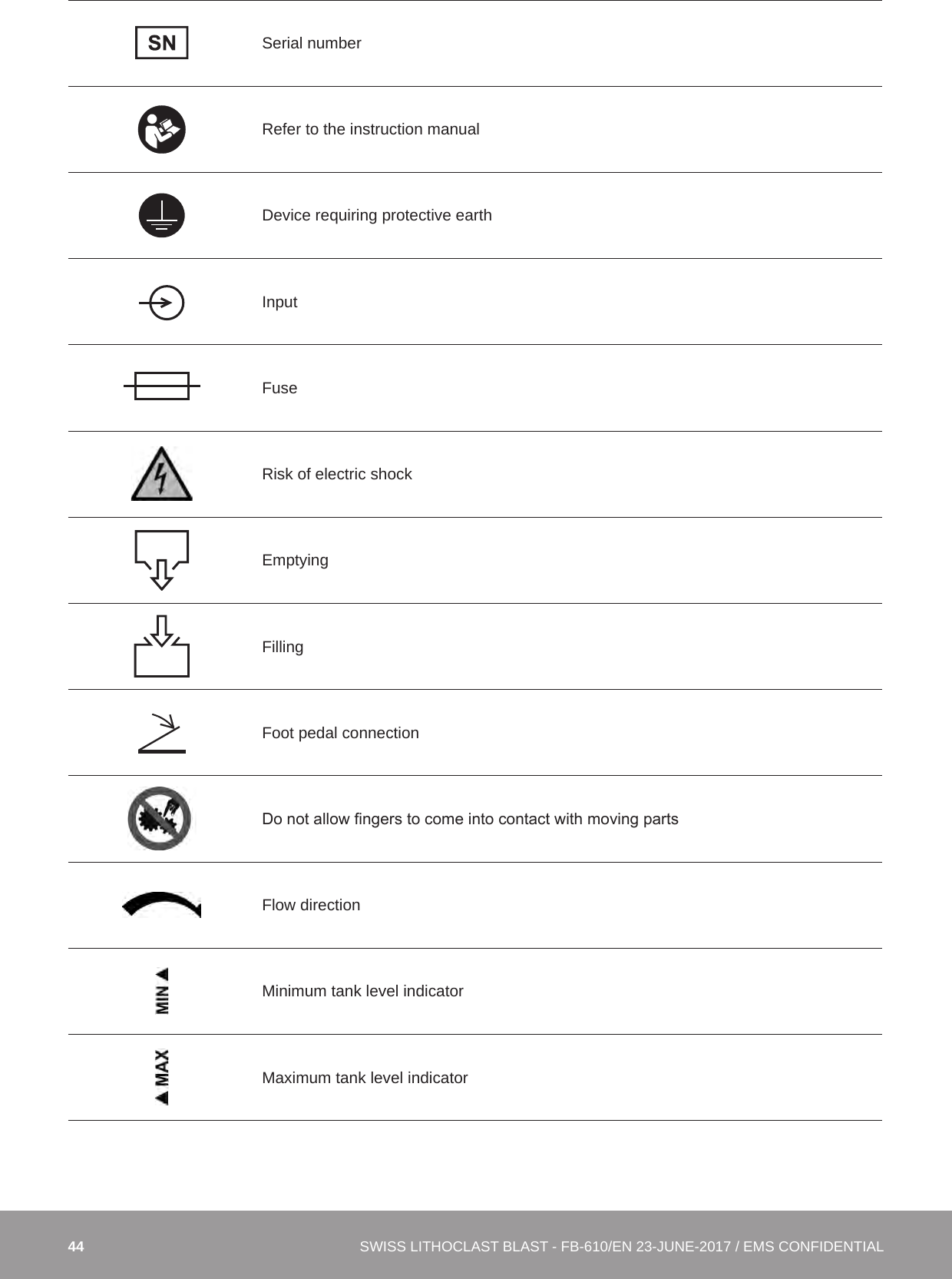
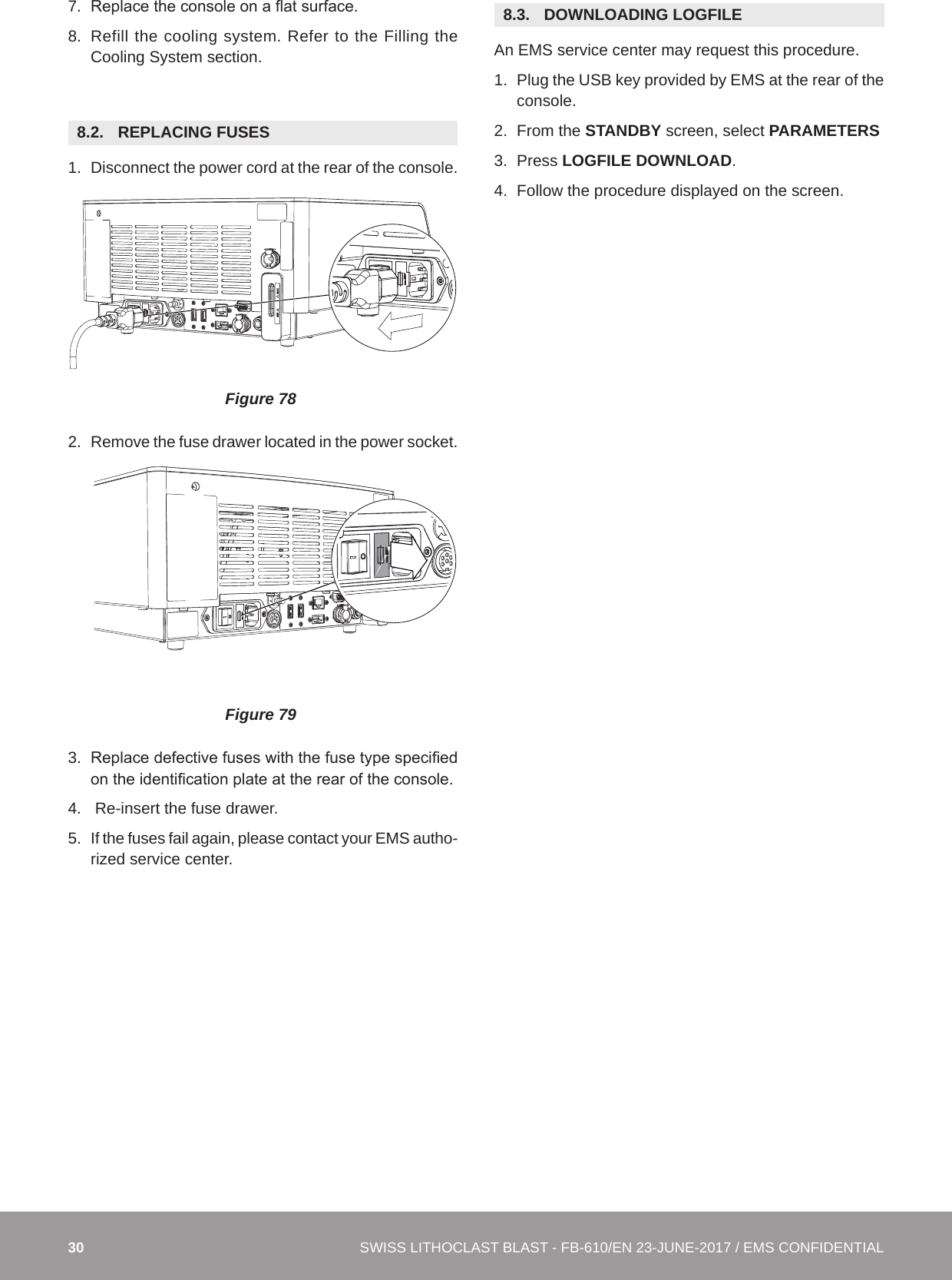
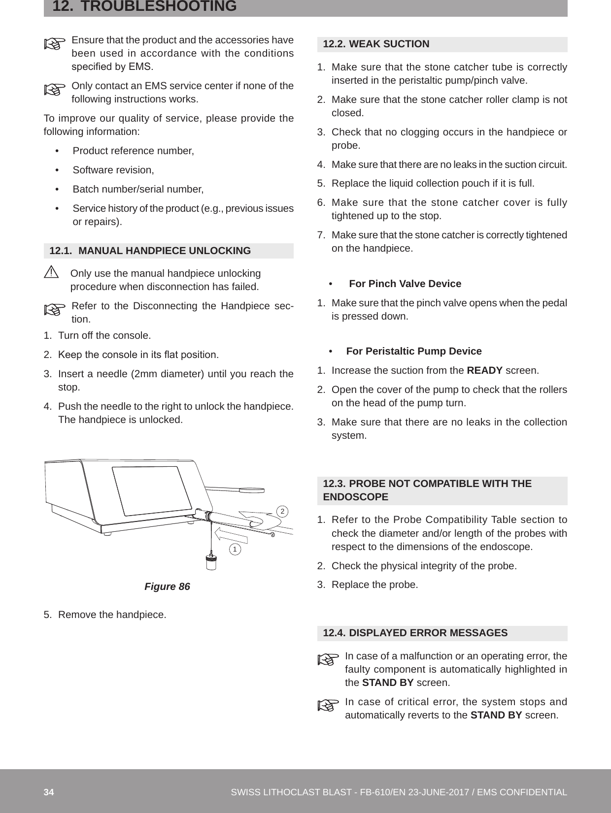
![27Step C2. Automated Cleaning, disinfection and drying processAutomated Cleaning, disinfection and drying validation has been performed using a Miele 7735CD washing machine, and the cleaning agent Neodisher® Mediclean. EMS recommends using Neodisher® Mediclean for their products.For this step, a Washer/Disinfector machine must have suitable baskets to hold small, fragile products and rinsing connections for the attachment to product lumina.The program of the Washer/Disinfector machine shall be able to perform the following steps. Place the instrument in a suitable rack and start the program. The Vario TD programs have been shown to be effective:• 2 min pre-washing with cold water (<40°C). Drain;• 5 min washing with 0.5% detergent at 55°C. Drain; • 3 min neutralising with warm water (>40°C). Drain; • 2 min intermediate rinsing with warm water (>40°C). Drain.Special instructions of the manufacturer for the Washer/Disinfector must be followed.Disinfection (if required by national laws)Automated Thermal Disinfection in a Washer/Disinfector taking into consideration national requirements in regards to A0-Value (see EN 15883) e.g. 93°C for 3 minutes.A machine cleaning and disinfection method should always be used for cleaning/disinfection because of the increased effectiveness of this method. Sterilization must be performed after disinfection.DryingDrying of outside of instrument through drying cycle of the Washer/Disinfector. If needed, additional manual drying can be performed using a lint-free towel and filtered compressed air (max. pressure 3 bar).The instrument must never be heated >138°C.Step D. Functional Testing, MaintenanceIf stains are still visible on the product after cleaning/disinfection, the entire cleaning/disinfection procedure must be repeated. Products with visible damage, chips/akes, corrosion or bent out of shape must be disposed of (no further use is permissible).Step E. Packaging for sterilizationPrior to sterilization, the products must be placed in a suitable sterilization container or sterilization packaging: Compliant with EN ISO 11607 or EN 868.Step F. SterilizationSterilization of instruments by applying a fractionated pre-vacuum process (according ISO 13060 and ISO 17665) taking into consideration the respective country requirements.Do not exceed the maximum number of sterilization cycles, please refer to the instruction manual.Step F1. Prevacuum sterilizationParameters for the pre-vacuum cycle:• 3 prevacuum phases• Sterilization temperature of 132°C for 3 minutes• Drying time: minimum 20 min• Do not exceed a sterilization temperature of 138°C and a holding time of 20 min. Step K. StorageStorage of sterilized instruments in a dry, clean and dust free environment at modest temperatures of 5°C to 40°C.[Doigts] Handpiece must have the lumen positionned verticaly in the sterilizer](https://usermanual.wiki/E-M-S-Electro-Medical-Systems/GRDLNBPVMEO.User-manual-1-2ANZC-GRDLNBPVMEO-pdf/User-Guide-3655506-Page-27.png)
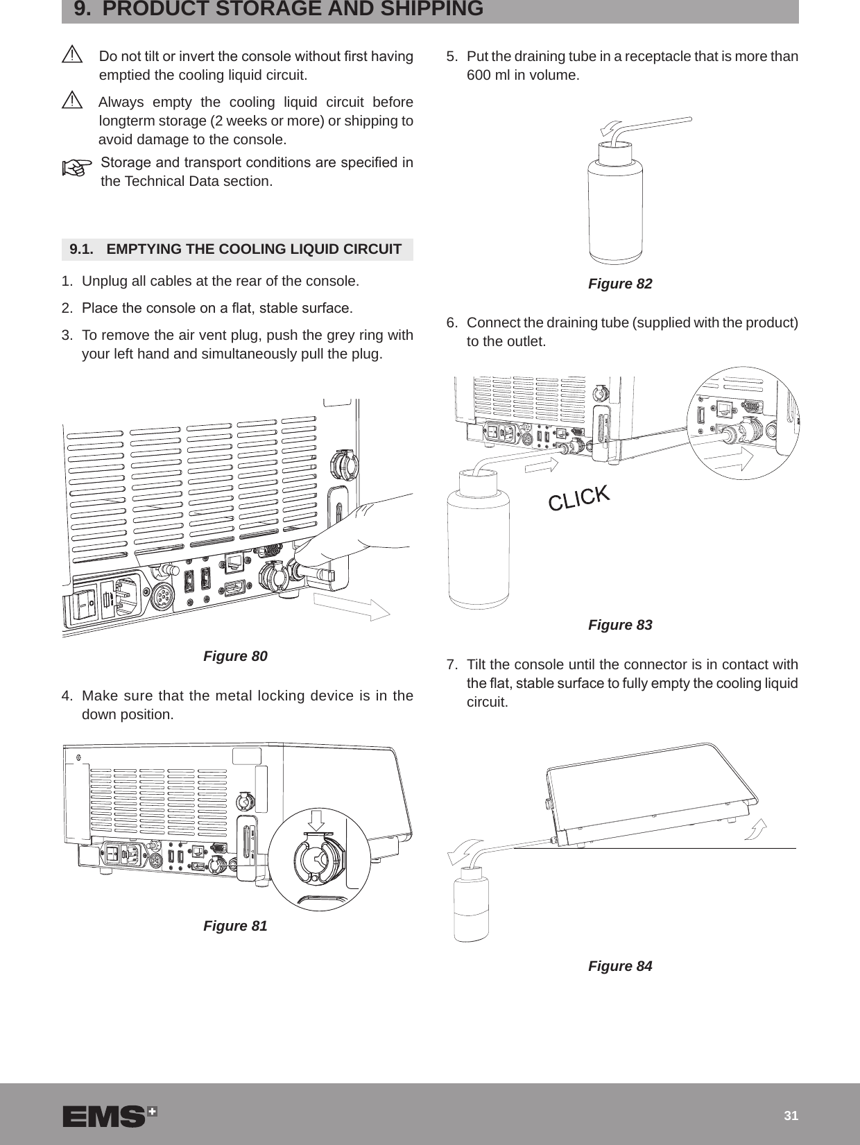
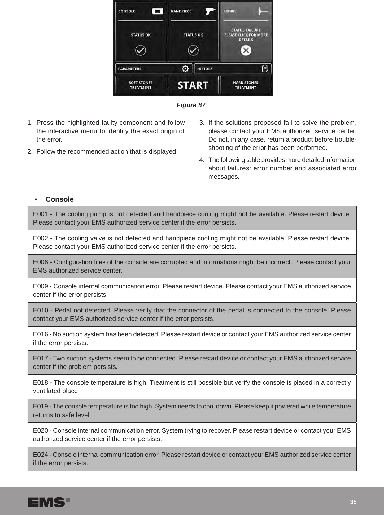
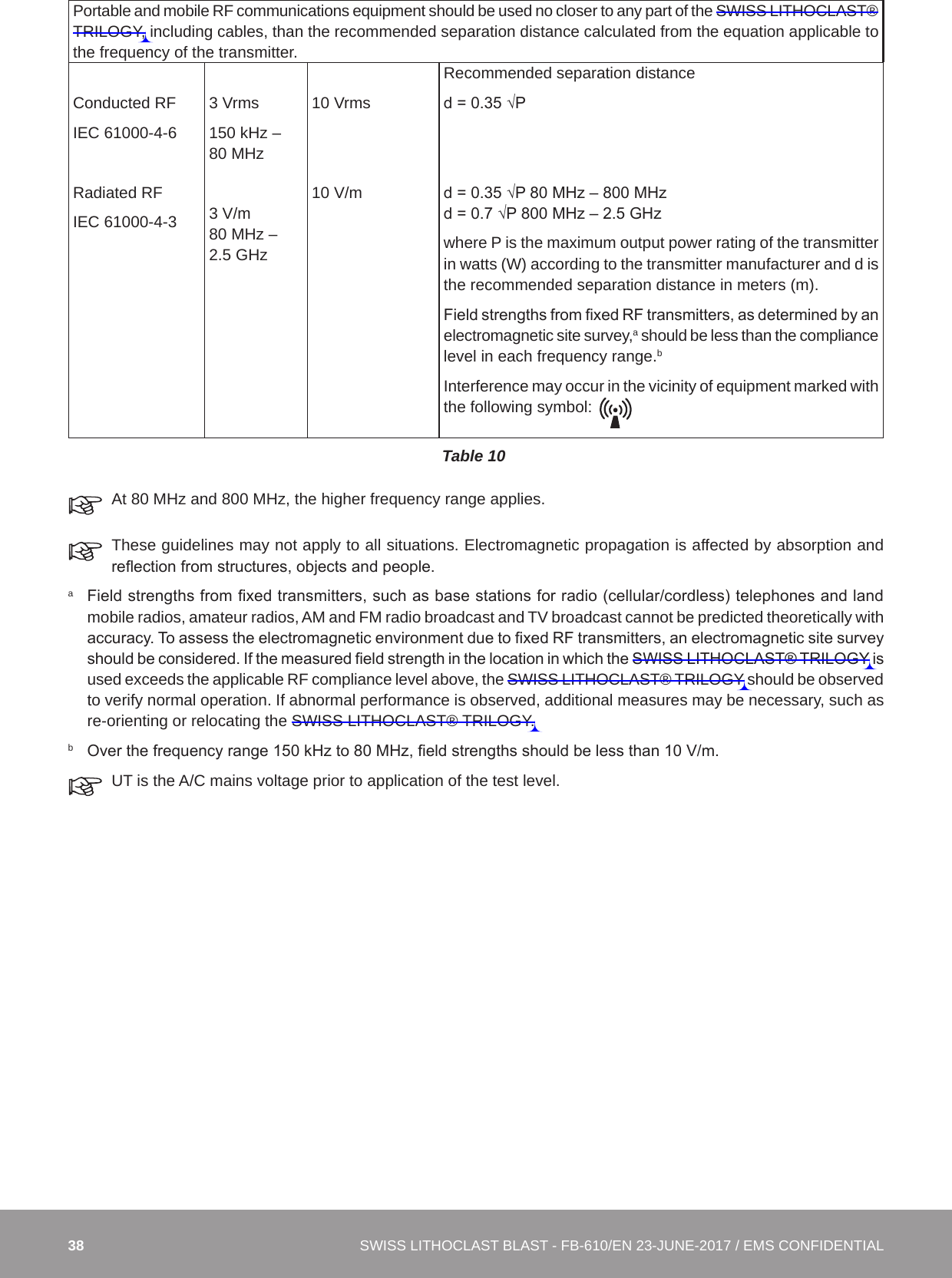
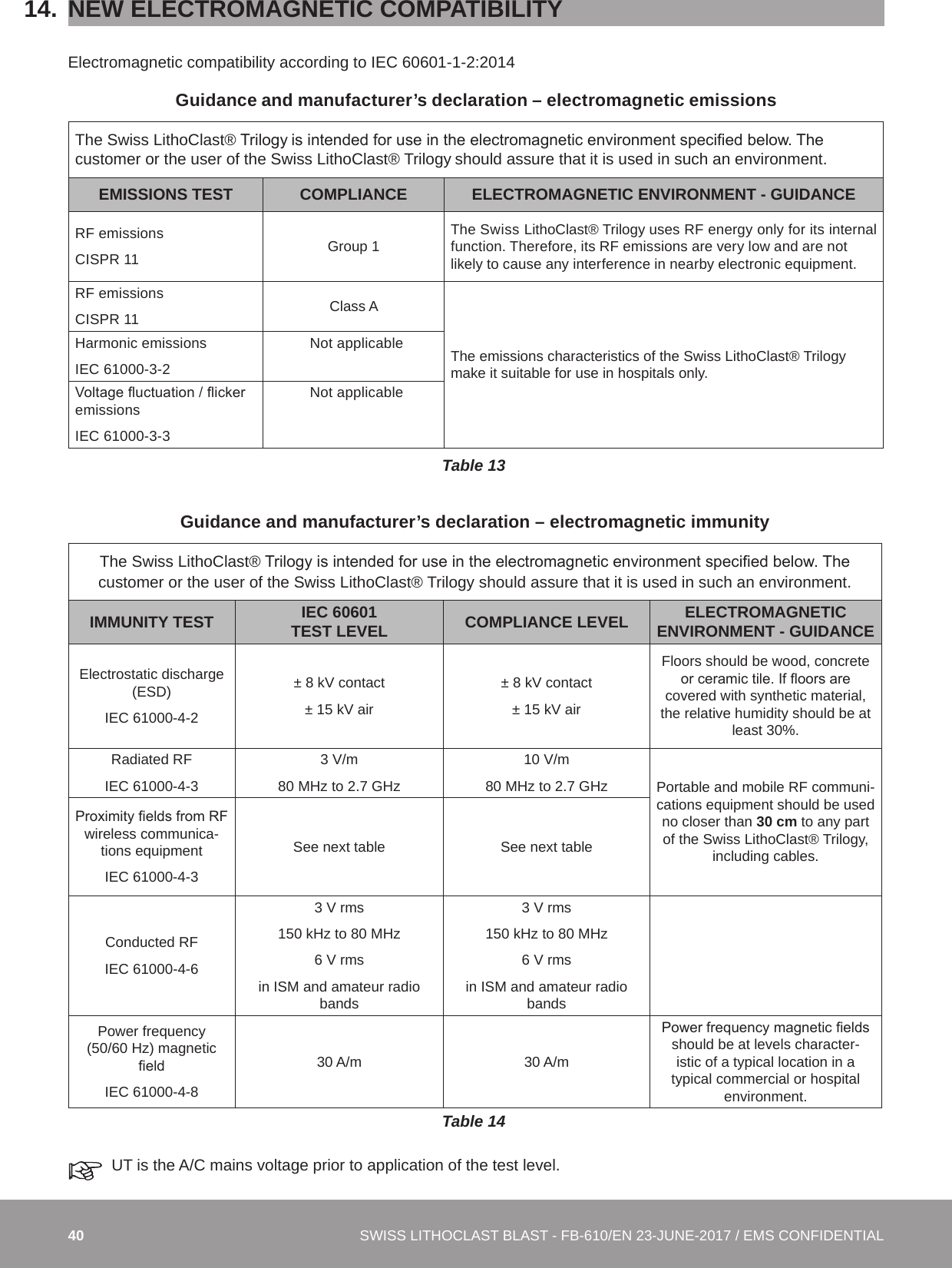
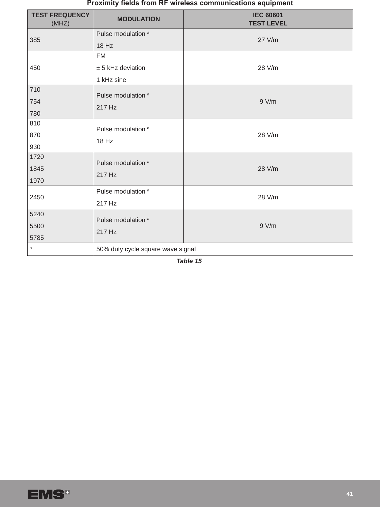
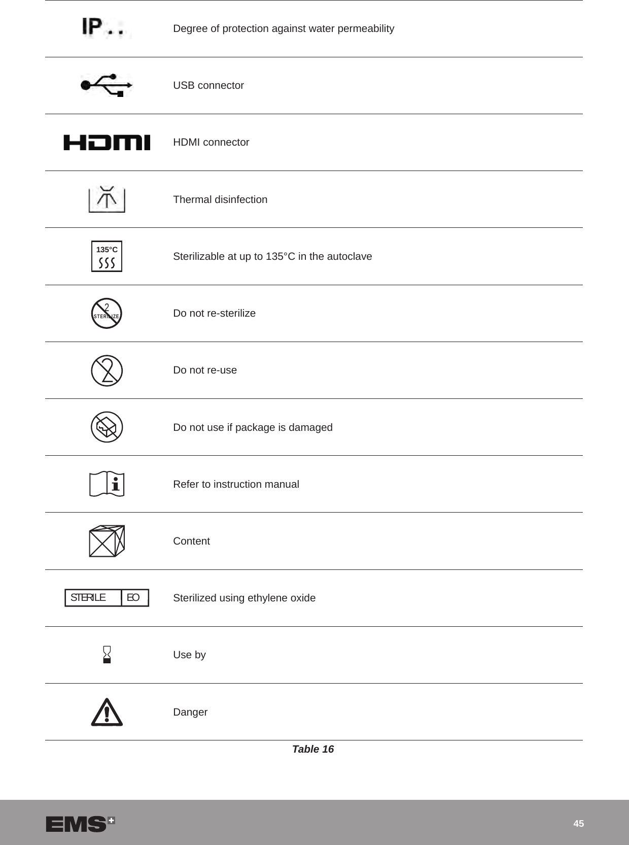
![39Recommended separation distances between portable and mobile RF communications equipment and the SWISS LITHOCLAST® TRILOGYThe SWISS LITHOCLAST® TRILOGY is intended for use in an electromagnetic environment in which radiated RF disturbances are controlled. The customer or the user of the SWISS LITHOCLAST® TRILOGY can help prevent electromagnetic interference by maintaining a minimum distance between portable and mobile RF communications equipment (transmitters) and the SWISS LITHOCLAST® TRILOGY as recommended below, according to the maximum output power of the communications equipment.Rated maximum output power of transmitter [W]Separation distance according to frequency of transmitter [m]150 kHz to 80 MHzd = 0.35 √P 80 MHz to 800 MHzd = 0.35 √P800 MHz to 2.5 GHzd = 0.7 √P0.01 0.04 m 0.04 m 0.07 m0.1 0.13 m 0.13 m 0.22 m1 0.4 m 0.4 m 0.7 m10 1.3 m 1.3 m 2.2 m100 4 m 4 m 7 mTable 11For transmitters rated at a maximum output power not listed above, the recommended separation distance (d) in meters (m) can be estimated using the equation applicable to the frequency of the transmitter, where power (P) is the maximum output power rating of the transmitter in watts (W) according to the transmitter manufacturer. At 80 MHz and 800 MHz, the separation distance for the higher frequency range applies. These guidelines may not apply to all situations. Electromagnetic propagation is affected by absorption and reection from structures, objects and people.Compliant cables and accessoriesThe use of accessories and cables other than those specied or sold by EMS as replacement parts may result in increased emissions or decreased immunity of this product.Cables and accessories Maximum length Complies withHandpiece cordPedal2.9 m2.9 mCISPR 11 Class B / Group 1: RF electromagnetic disturbanceIEC 61000-4-2 Electrostatic discharge (ESD) IEC 61000-4-3 Electromagnetic elds radiated by radio-frequenciesIEC 61000-4-4 Electric fast transient / burstIEC 61000-4-5 SurgeIEC 61000-4-6 Disturbances induced by radio-frequency elds IEC 61000-4-8 Power frequency magnetic eld (50/60 Hz) IEC 61000-4-11 Voltage dips, short interruptions and voltage variationsTable 12Essential performanceThe SWISS LITHOCLAST® TRILOGY has neither life sustaining functions nor diagnostic of life supporting functions.](https://usermanual.wiki/E-M-S-Electro-Medical-Systems/GRDLNBPVMEO.User-manual-1-2ANZC-GRDLNBPVMEO-pdf/User-Guide-3655506-Page-39.png)