E M S Electro Medical Systems GRDLNBPVMEO Intracorporeal lithotripter User Manual 2 EN 2ANZC GRDLNBPVMEO
E.M.S. Electro Medical Systems S.A. Intracorporeal lithotripter 2 EN 2ANZC GRDLNBPVMEO
Contents
- 1. User manual 1 - 2ANZC-GRDLNBPVMEO.pdf
- 2. User manual 2 EN- 2ANZC-GRDLNBPVMEO.pdf
- 3. User manual 2 FR- 2ANZC-GRDLNBPVMEO.pdf
User manual 2 EN- 2ANZC-GRDLNBPVMEO.pdf

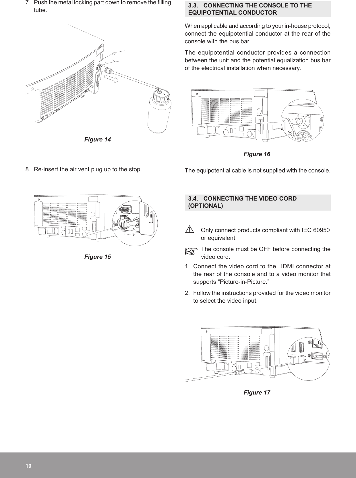
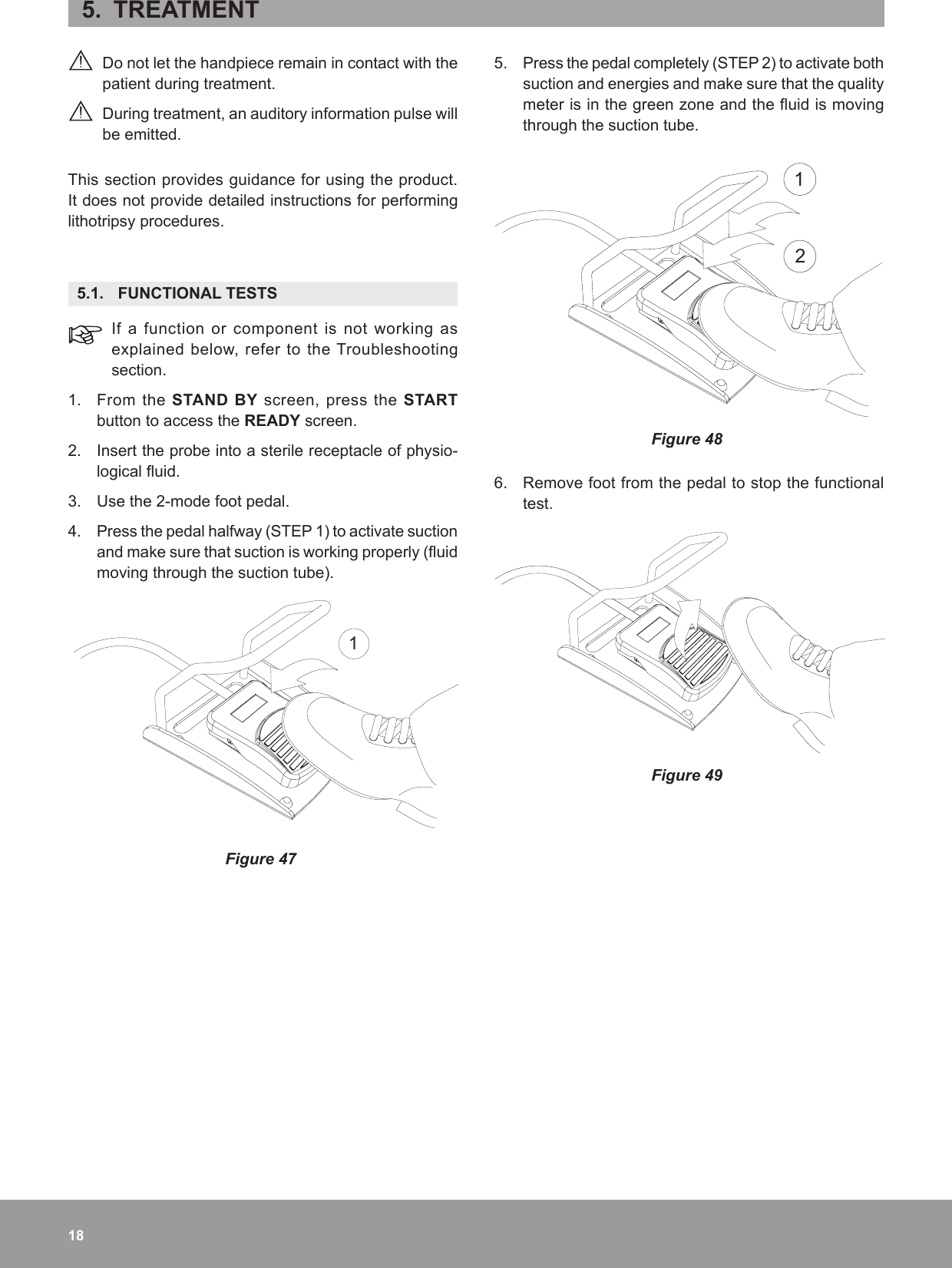
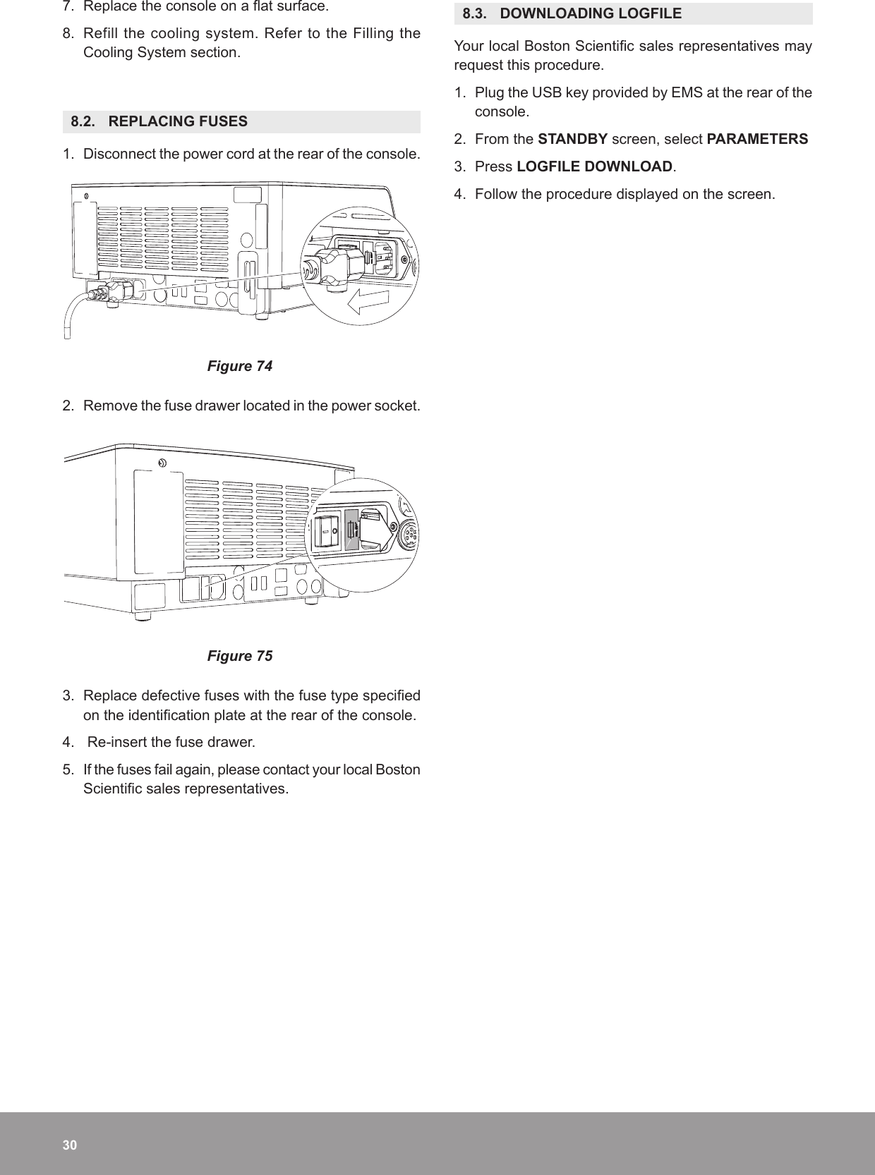
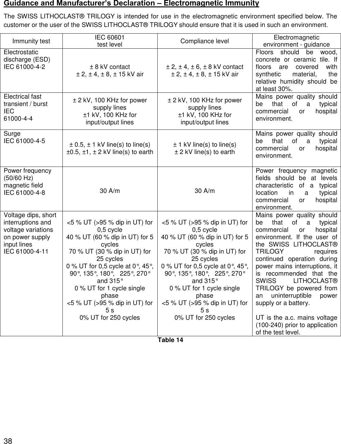
![Guidance and Manufacturer’s Declaration – Electromagnetic Immunity The SWISS LITHOCLAST® TRILOGY is intended for use in the electromagnetic environment specified below. The customer or the user of the SWISS LITHOCLAST® TRILOGY should ensure that it is used in such an environment. Portable and mobile RF communications equipment should be used no closer to any part of the SWISS LITHOCLAST® TRILOGY, including cables, than the recommended separation distance calculated from the equation applicable to the frequency of the transmitter. These guidelines may not apply to all situations. Electromagnetic propagation is affected by absorption and reflection from structures, objects and people. Field strengths from fixed transmitters, such as base stations for radio (cellular/cordless) telephones and land mobile radios, amateur radios, AM and FM radio broadcast and TV broadcast cannot be predicted theoretically with accuracy. To assess the electromagnetic environment due to fixed RF transmitters, an electromagnetic site survey should be considered. Immunity Test IEC 60601 Test Level Compliance level Electromagnetic Environment –GuidanceConducted RF IEC 61000-4-6 3 V rms 150 kHz to 80 MHz 6 V rms in ISM and amateur radio bands 3 V rms 150 kHz to 80 MHz 6 V rms in ISM and amateur radio bands If the measured field strength in the location in which the SWISS LITHOCLAST® TRILOGY is used exceeds the applicable RF compliance level above, the SWISS LITHOCLAST® TRILOGY should be observed to verify normal operation. If abnormal performance is observed, additional measures may be necessary, such as re-orienting or relocating the SWISS LITHOCLAST® TRILOGY. Radiated RF IEC 61000-4-3 3 V/m 80 MHz to 2.7 GHz 80% AM at 1KHz 3 V/m 80 MHz to 2.7 GHz 80% AM at 1KHz Minimum separation distance shall be calculated by following equation: E is the immunity test level in [V/m] d is the minimum separation in [m] P is the maximum power in [W]39](https://usermanual.wiki/E-M-S-Electro-Medical-Systems/GRDLNBPVMEO.User-manual-2-EN-2ANZC-GRDLNBPVMEO-pdf/User-Guide-3655507-Page-39.png)
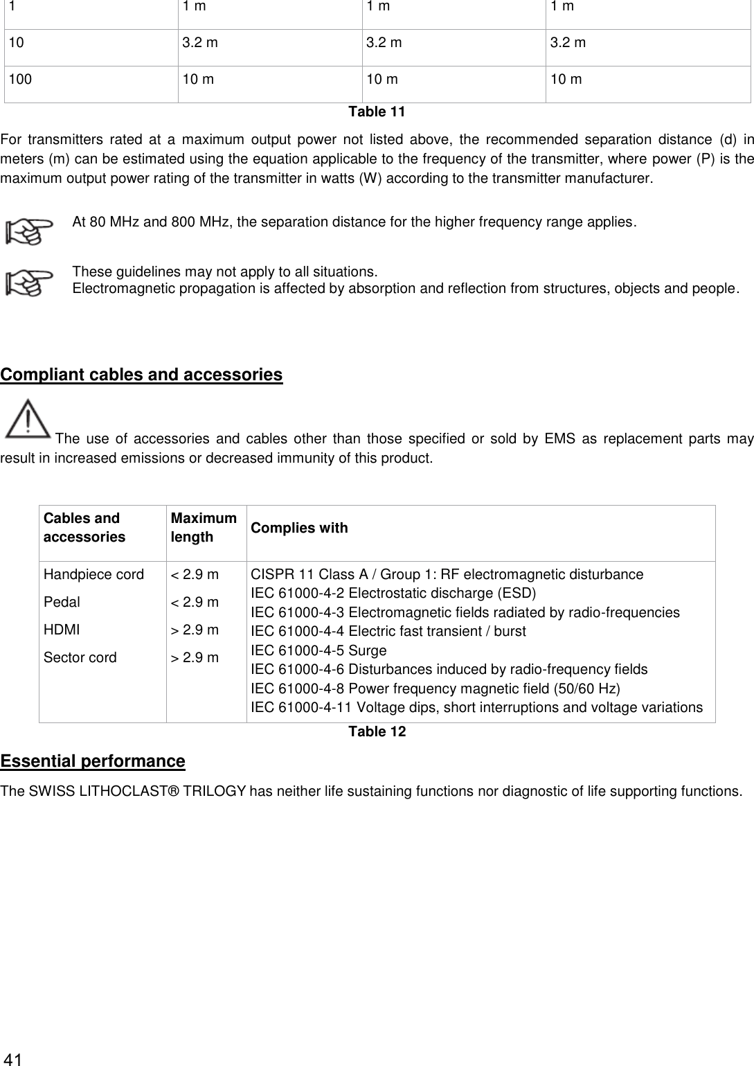
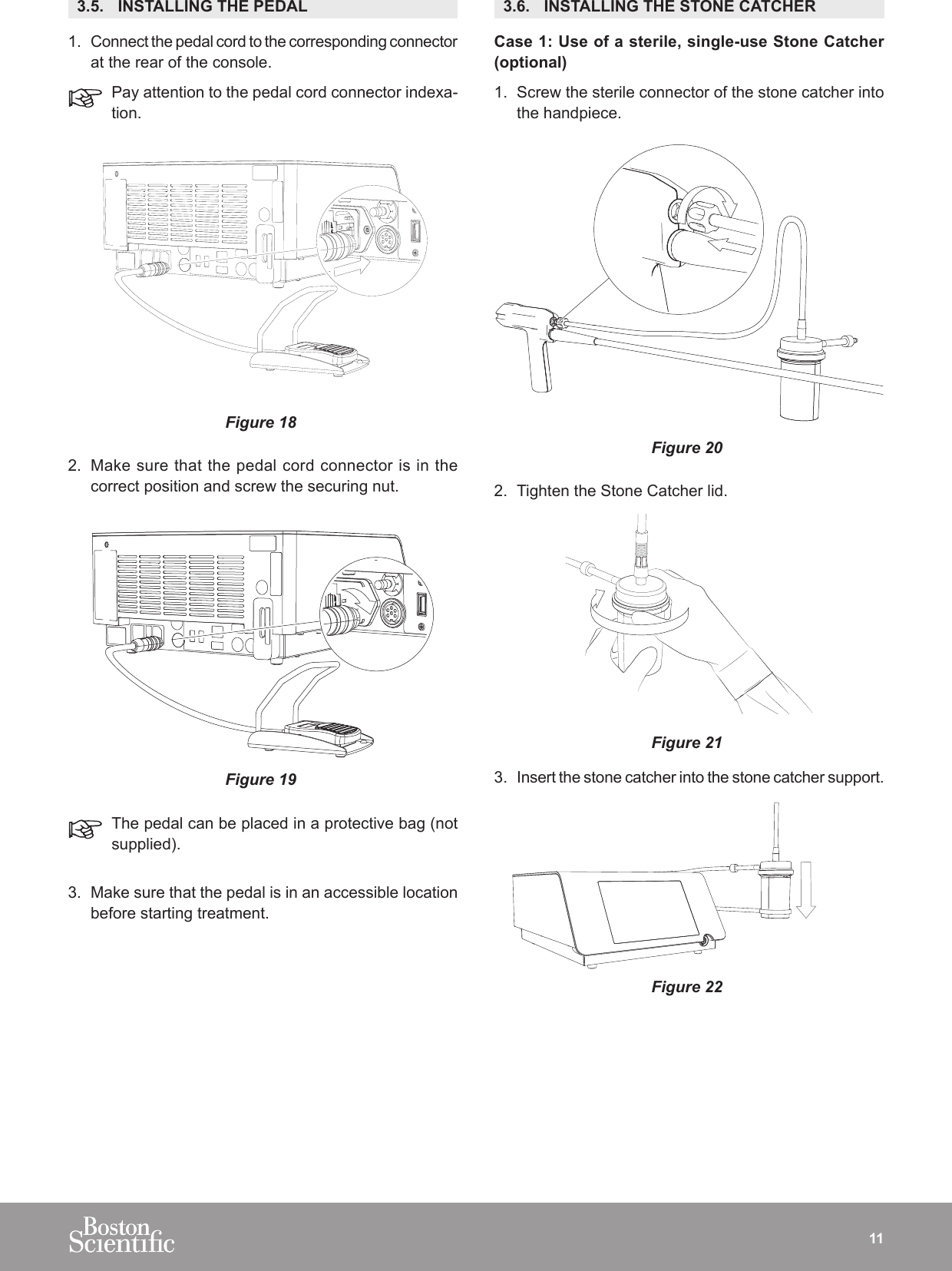
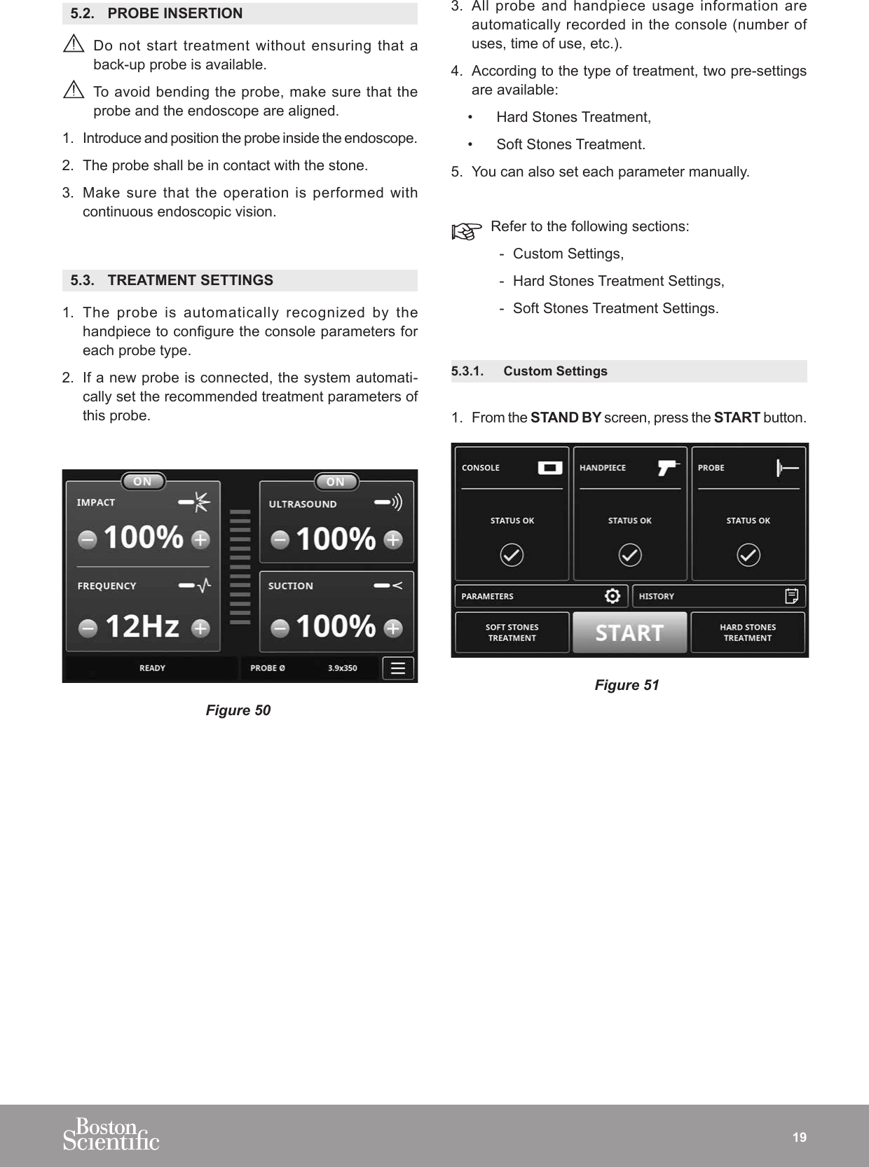
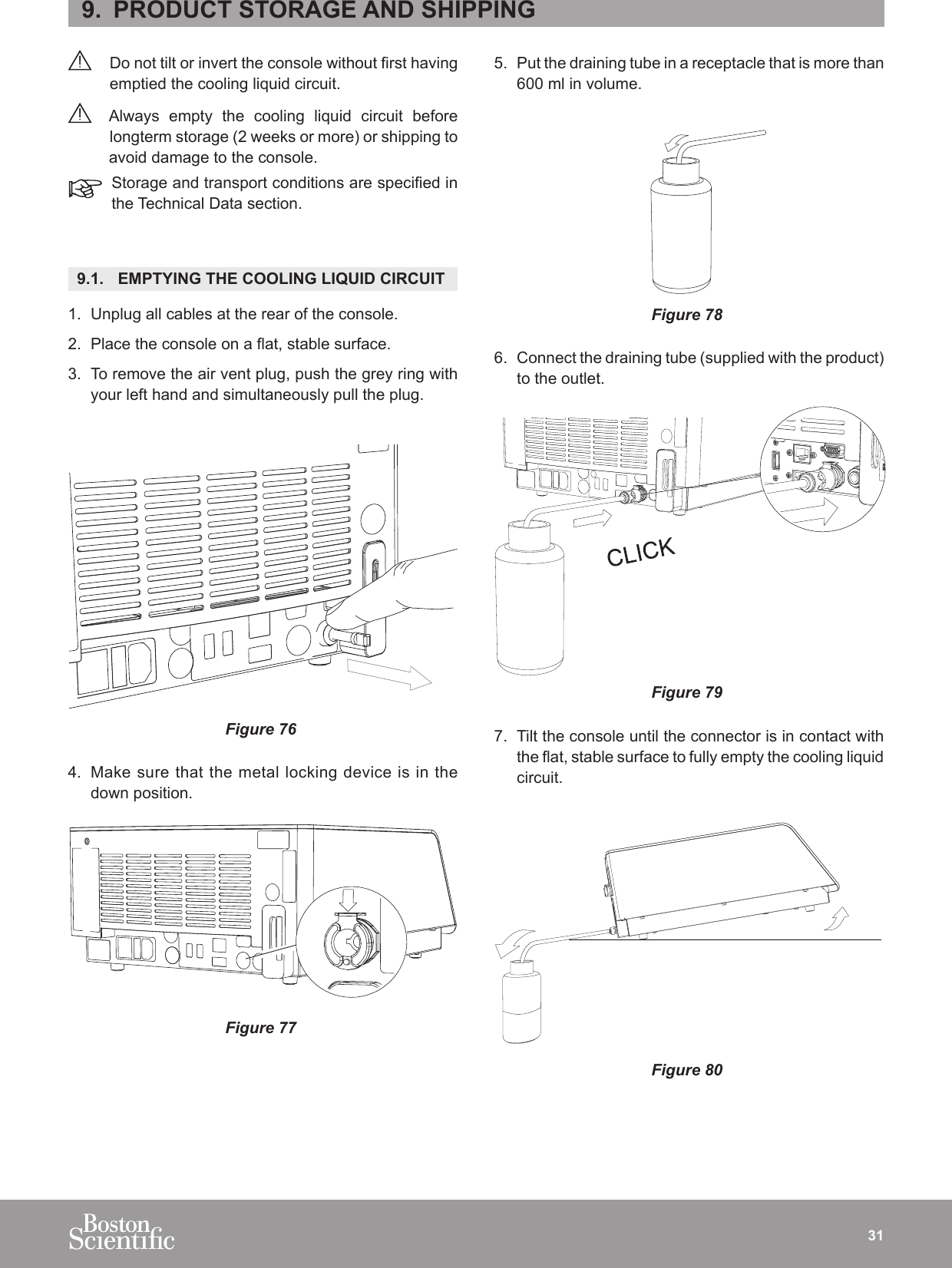
![Proximity fields from RF wireless communications equipment IEC 61000-4-3 27 V/m 380-390 MHz50% PM 18 Hz28 V/m 430-470 MHzFM ±5 kHz deviation, 1kHz sine9 V/m 704-787 MHz50% PM 217 Hz28 V/m 800-960 MHz50% PM 18 Hz28 V/m 1700-1990 MHz 50% PM 217 Hz 28 V/m 2400-2570 MHz 50% PM 217 Hz 9 V/m 5100-5800 MHz 50% PM 217 Hz 27 V/m 380-390 MHz50% PM 18 Hz28 V/m 430-470 MHzFM ±5 kHz deviation, 1kHz sine9 V/m 704-787 MHz50% PM 217 Hz28 V/m 800-960 MHz50% PM 18 Hz28 V/m 1700-1990 MHz 50% PM 217 Hz 28 V/m 2400-2570 MHz 50% PM 217 Hz 9 V/m 5100-5800 MHz 50% PM 217 Hz RF wireless equipment maximum output power and separation distance tested (at 30 cm): TETRA 400: max 1.8 W GMRS 460, FRS 460: max 2 W LTE Band 13, 17: max 0.2 W GSM 800/900: max 2 W TETRA 800: max 2W iDEN 820: max 2W CDMA 850: max 2 W LTE Band 5: max 2W GSM 1800/1900: max 2 W CDMA 1900: max 2W DECT: max 2 W LTE Band 1,3,4,25: max 2 W UMTS: max 2W Bluetooth: max 2W WLAN 802.11b/g/n: max 2W RFID 2450: max 2W LTE Band 7: max 2 W WLAN 802.11 a/n: max 0.2 W Interference may occur in the vicinity of equipment marked with the following symbol: If the measured field strength in the location in which the SWISS LITHOCLAST® TRILOGY is used exceeds the applicable RF compliance level above, the SWISS LITHOCLAST® TRILOGY should be observed to verify normal operation. If abnormal performance is observed, additional measures may be necessary, such as reorienting or relocating the SWISS LITHOCLAST® TRILOGY Table 9 Recommended separation distances between portable and mobile RF communications equipment and the SWISS LITHOCLAST® TRILOGY The SWISS LITHOCLAST® TRILOGY is intended for use in an electromagnetic environment in which radiated RF disturbances are controlled. The customer or the user of the SWISS LITHOCLAST® TRILOGY can help prevent electromagnetic interference by maintaining a minimum distance between portable and mobile RF communications equipment (transmitters) and the SWISS LITHOCLAST® TRILOGY as recommended below, according to the maximum output power of the communications equipment. Rated maximum output power of transmitter [W] Separation distance according to frequency of transmitter [m] 150 kHz to 80 MHz outside ISM and amateur bands d = 1.0 150 kHz to 80 MHz in ISM and amateur bands d = 1.0 80 MHz to 2700 MHz (for define RF Wireless transmitter see table before) d = 1.0 0.01 0.1 m 0.1 m 0.1 m 0.1 0.32 m 0.32 m 0.32 m 40](https://usermanual.wiki/E-M-S-Electro-Medical-Systems/GRDLNBPVMEO.User-manual-2-EN-2ANZC-GRDLNBPVMEO-pdf/User-Guide-3655507-Page-40.png)