E TECH IM100 Private Land Mobile Radio for Vehicle (VHF) User Manual IM100 users manual
E-TECH Co., Ltd. Private Land Mobile Radio for Vehicle (VHF) IM100 users manual
E TECH >
Contents
- 1. User Manual Part 1
- 2. User Manual Part 2
User Manual Part 2

FILE: IM 100 service manual.doc 2004.11.23
E-TECH Co., Ltd 1/19
▶User’s Manual◀
1. Introduction
2. Description of Unit
3. Technical Specification
4. Features and Operation
5. Antenna Installation
192 - 2 -219
FILE: IM100 manual.doc 2004.11.23
E-TECH Co., Ltd 2/19
1. Introduction
IM100 has a compact size with a various features in the range of 136~174MHz. IM100
Has a various features shown as below.
IM100 constructed with a microprocessor controlled, temperature compensated Phase Locked
Loop(PLL) frequency synthesizer. The radio features a double conversion receiver and a direct FM
transmitter modulator. A special integrated circuit provides support to sub-audible signaling(CTCSS & DCS)
and most of the receiving parts are switched off periodically in the power save mode to reduce battery current
drain during standby.
2. Description of Unit
Items Model
Radio IM100
Supplied
Package User manual
Items Model
Hand Microphone
VOX & PTT Headset
Power Cable
Accessories
Pedestal

193 - 3 -319
FILE: IM100 manual.doc 2004.11.23
E-TECH Co., Ltd 3/19
3. Technical Specifications
3-1 General
1) Frequency range : 136~174 MHz
2) Channels : 255 Channels
3) Channel spacing : 12.5 kHz/25 kHz
4) Communication method : Simplex
5) Antenna Impedance : 50 ohm
6) Power supply voltage : DC 13.6V
7) Current Drain : When Transmitting(50W) - < 13A
When Receiving(5W) - < 1A
Transmit standby - < 100mA
8) Microphone : External Condenser Mic
9) Operating temperature range: -30 +℃∼ 60℃
10) Size : 178(W)x49(H)x195(D)
11) Weight : 1600g
3-2 Transmitter
1) Power Output : HIGH – 50W, LOW - 5W
2) Modulation : 8K50F3E/16K0F3E
3) Oscillator method : PLL
4) Frequency Stability : less than ±0.00025% (±2.5PPM)
5) Maximum frequency deviation: ±2.5 kHz(Narrow)/ ±5 kHz(Wide)
6) Audio Distortion : less than 5% (1 kHz 60%)
7) SPURIOUS Emission : -70 [dBc]
8) FM Hum & Noise : -40 / -45 [dB] (HP8920A 300Hz 3kHz BP∼F)
9) BAND SPREAD : 38 [MHz]
194 - 4 -419
FILE: IM100 manual.doc 2004.11.23
E-TECH Co., Ltd 4/19
3-3 Receiver
1) Receiver Type : Double Super Hetero type
2) Sensitivity : -0.25uV 이하(12dB SINAD 시)
3) Frequency Stability : ±0.00025%(±2.5PPM)
4) SPURIOUS Rejection : -75 dB
5) Adjacent Channel Selectivity: -65 dB (Narrow) , -70 dB (Wide)
6) Distortion : 5% (1 kHz 60%)
7) Hum & Noise : -40 / -45 dB(HP8920A 300Hz 3kHz BPF)∼
8) Audio output : Normal 3W ( Max 5W )
9) BAND SPREAD : 38MHz
10) Speaker size : 48 * 30 Rectangle
4. Features and Operation
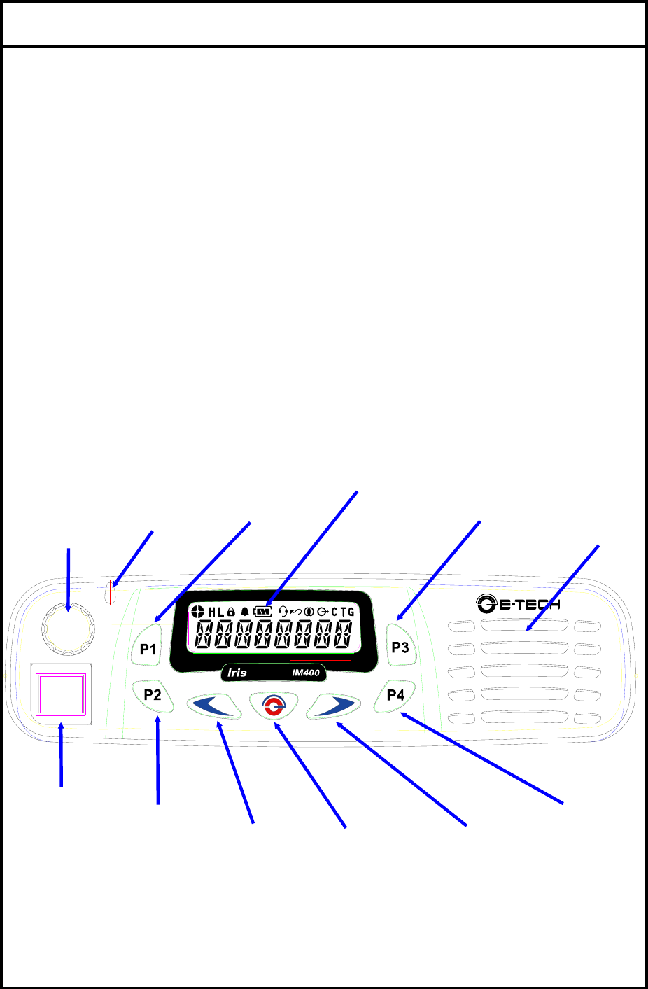
EXTERNAL VIEW
4)Emergency
Key
11)POWER ON/OFF
&Volume control
13)Ear/Mic Jack
PC-Programming
Jack
14)LCD
6)Menu Button
8)Squelch
14)SPEAKER
3)DOWN button
2)Monitor Button
1)TX POWER
HIGH
/
LOW
9) LED I
3)UP button

195 - 5 -519
FILE: IM100 manual.doc 2004.11.23
E-TECH Co., Ltd 5/19
4-1 Features & Operation
1. Monitor
Press the Monitor key momentarily to disable the Tone squelch.
2. Radio Call
By using Various 5Tone, individual / Group call is available.
16 Receiving codes are available as well as open call.
3. Missed calls list
16 Missed calls can be listed. If a call remains unanswered, the call will be stored
by the radio.
4. contact list
During a call, the contact list may be used to give access to up to 16 preprogrammed
numbers accessed via the menu.
5. status list
A status is a code for transmitting prearranged messages, e.g. status “05” may indicate
“launch”. Status list contains up to 30 entries.
6. Channel : 255 channel
7. Scan ON/off
8. Power level : Power level is adjustable in each channel respectively.
9. Talkaround on/off
10. Emergency :
11. Lone Worker
12. Tx Tone select : In the menu, tx dcs /ctcss tone is adjustable.
13. Rx Tone select : In the menu, rx dcs /ctcss tone is adjustable.
14. Group : Defines group tone. You can select tone code for group, and it is used as a default value
. 0~9 and a, b, c, d available. And “A” is used as a basic value..
15. BEEP ON/OFF : BEEP sound ON/OFF.
16. KEY LOCK : LOCK/UNLOCK Button KEY.
17. SQUELCH : Squelch level is adjustable
18. AUTO SQUELCH : Squelch level is adjustable automatically by surroundings.
19. DTMF ON/OFF : DTMF function is available.
20. VOX : VOX LEVEL is adjustable by pushing up and down button.
21. AUTO VOX : VOX level is adjustable automatically by surroundings.
22. P - SCAN : Priority Scan
23. POWER SAVE : Power save mode is available.
24. PASS WORD : This function is useful for security reason.
25. LOCATION INDICATE : Indicate where the radio is located by blinking green light every 7 seconds.
26. SCRMABLE : Internal Voice Scrambler is available.
27. STUN / UNSTUN : For added security and to avoid abuse of the radio system in which you operate
a feature known as Stun/Unstun is included in your radio.
28. BACKLIGHT : Lamp is lighting when you check LCD status.
196 - 6 -619
FILE: IM100 manual.doc 2004.11.23
E-TECH Co., Ltd 6/19
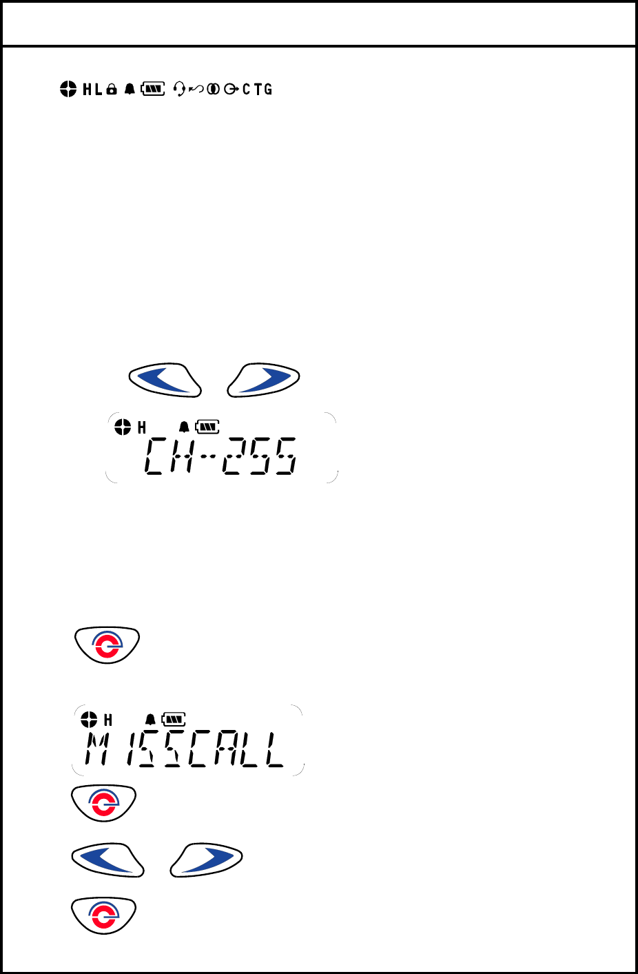
4-2 LCD Display and Icons
1.ANT GAZE ; Shows the received signal strength.
2.TX POWER HIGH: Indicate power level
3.KEY LOCK: Appears during key lock function is ON.
4.ALART(BEEP) ON/OFF: Appears when beep sound is turned ON.
5.Battery level indicator: Indicates reaming battery power.
6.VOX ON/OFF: Appears when VOX function is turned On.
7.SCAN: Appears when Scan function is activated.
8.SCRAMBLE: Appears while the voice scrambler function is activated.
9.TALK AROUND Indicator.
4-3 Features
1. Channel
This radio offers up to 255 channels
1). By using or button, you can select the desired channel.
2. Missed calls list
Up to 16 calls can be stored. If the same radio calls more than once, only the most recent call is stored.
When fifteen calls have been stored by the radio, depending on the radio programming the sixteenth call
received may overwrite the first or not be stored by the radio.
1). to enter Menu Mode.
2) Display shows
3) to select
4) or to scroll list
5) to exit
197 - 7 -719
FILE: IM100 manual.doc 2004.11.23
E-TECH Co., Ltd 7/19
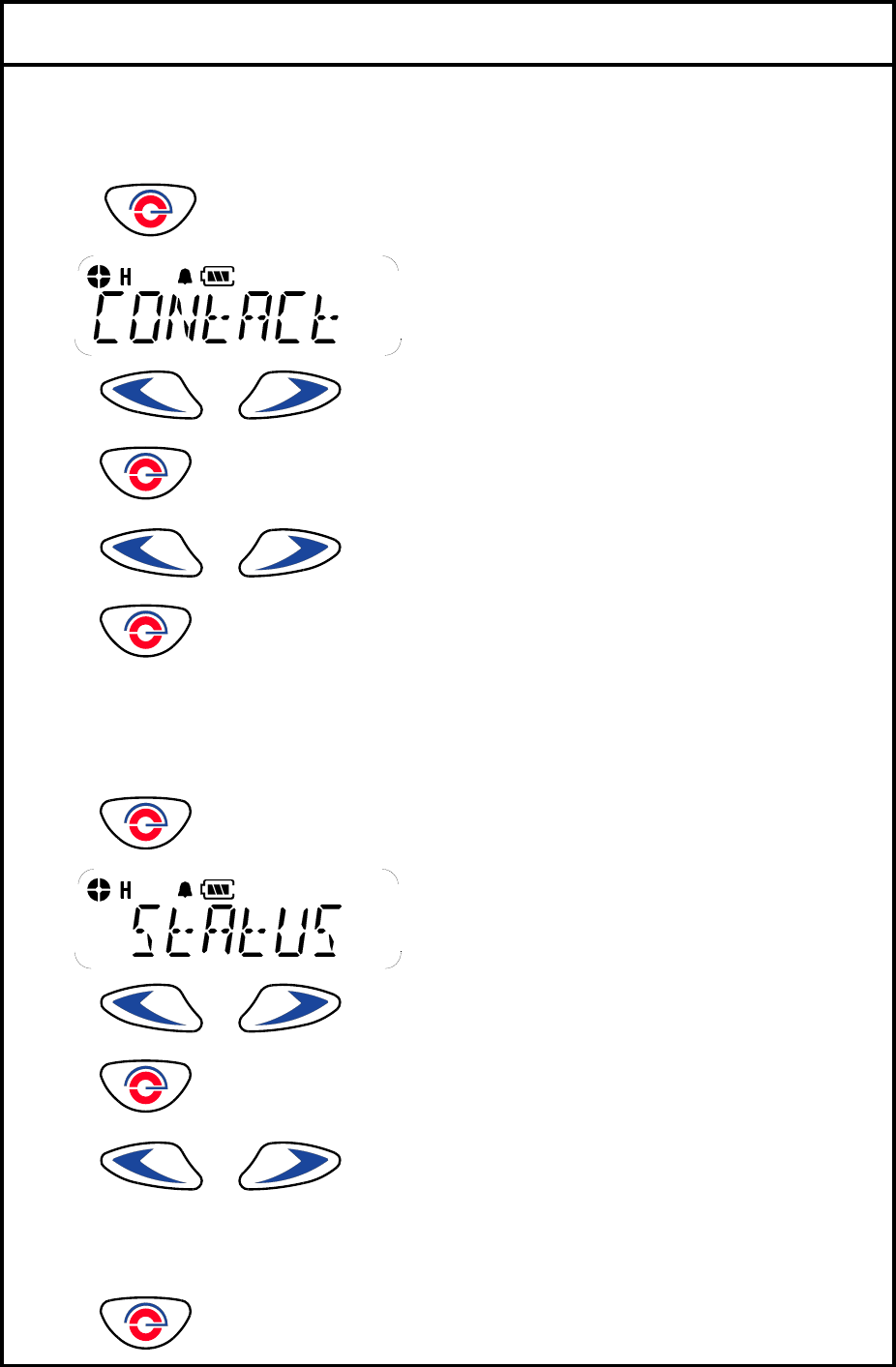
3. Contact list
1). to enter Menu Mode.
2) or to until
3) to select
4) or to scroll list
5) to exit
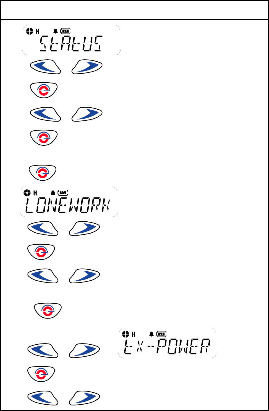
4. Status call list
4-1. Making STATUS call
1) to enter Menu Mode.
2) or to until
3) to select
4) or to scroll list
5) Push PTT KEY for sending message on the LCD.
4-2 Make STATUS Message
1) to enter Menu Mode.
198 - 8 -819
FILE: IM100 manual.doc 2004.11.23
E-TECH Co., Ltd 8/19
2) or to until
3) to select
4) or to scroll list
5) to SELECT
5. Lone work
1). to enter Menu Mode.
2) or to until
3) to select
4) or to select ON/OFF
6. Tx power
.1). to enter Menu Mode.
2) or to until
3) to select
4) or to select HIGH / LOW POWER
199 - 9 -919
FILE: IM100 manual.doc 2004.11.23
E-TECH Co., Ltd 9/19
5) to select
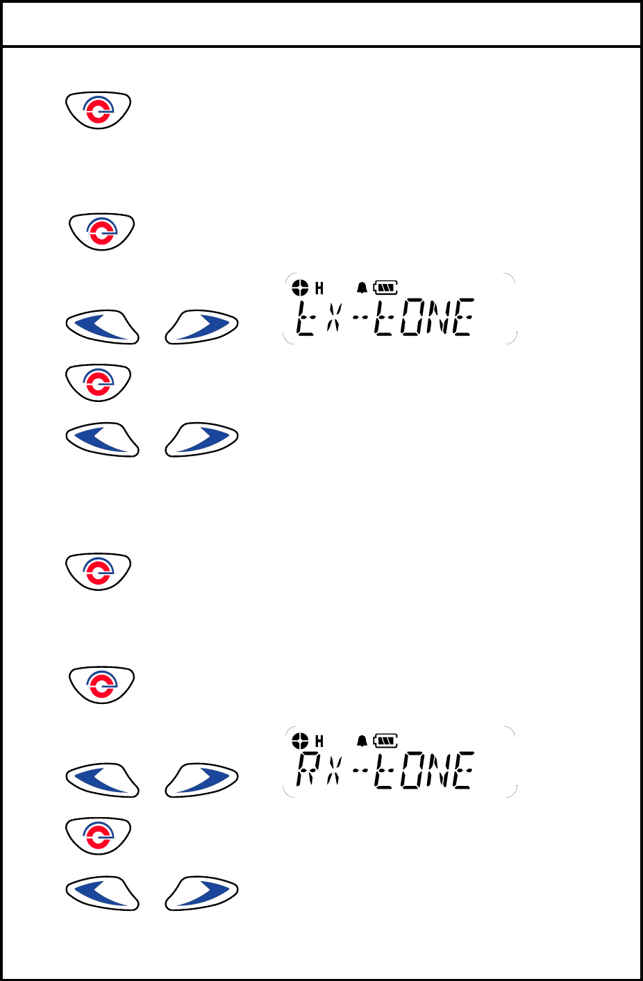
7. Tx Tone
Selecting Transmitting TONE(CTCSS/DCS).
1). to enter Menu Mode.
2) or to until
3) to select
4) or to Select TONE을 either CTCSS or DCS.
0= NON TONE
1-38 CTCSS
101 – 183 DCS TONE
5) to select exit
8. Rx Tone
Changing Receiving TONE(CTCSS/DCS).
1). to enter Menu Mode.
2) or to until
3) to select
4) or to select TONE either CTCSS or DCS.
0= NON TONE
1-38 CTCSS
101 – 183 DCS TONE.
1910 - 10 -1019
FILE: IM100 manual.doc 2004.11.23
E-TECH Co., Ltd 10/19
5) to select exit
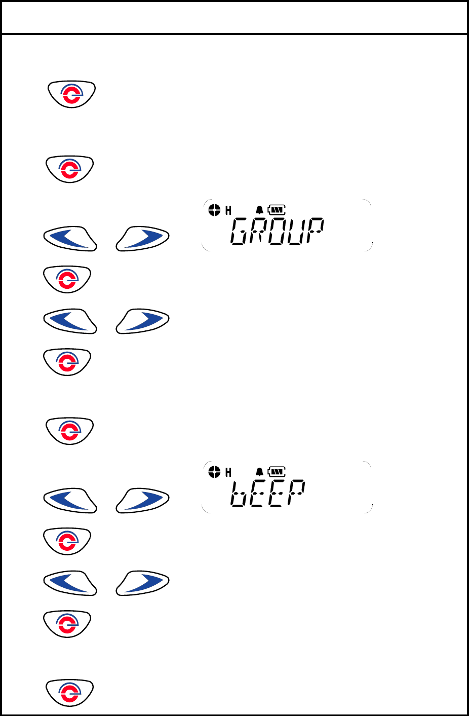
9. Group
Changing GROUP Tone.
1). to enter Menu Mode.
2) or to until
3) to select
4) or to select scroll list
5) to select exit
10. Beep on/off
1). to enter Menu Mode.
2) or to until
3) to select
4) or to select on off .
5) to select
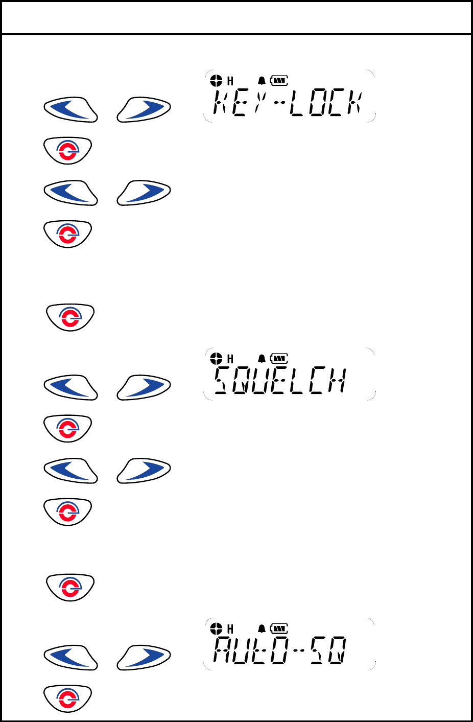
11. Key lock
1). to enter Menu Mode.
1911 - 11 -1119
FILE: IM100 manual.doc 2004.11.23
E-TECH Co., Ltd 11/19
2) or to until
3) to select
4) or to select key lock /unlock.
5) to select
12. Squelch level
16 level is available. 0 = terminate sq function
1). to enter Menu Mode.
2) or to until
3) to select
4) or to the scroll list
5) to select exit
13. Auto Squelch
1). to enter Menu Mode.
2) or to until
3) to select
1912 - 12 -1219
FILE: IM100 manual.doc 2004.11.23
E-TECH Co., Ltd 12/19
4) or to select on /off .
5) to select
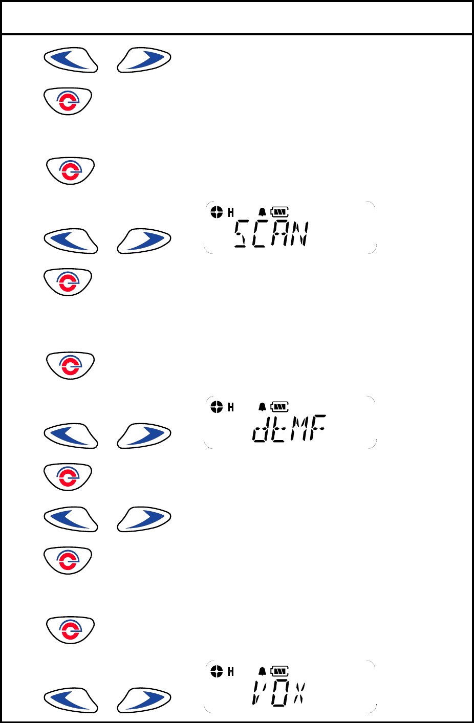
14. Scan
1). to enter Menu Mode.
2) or to until
3) to scan.
4) Push PTT for exit
15. DTMF
1). to enter Menu Mode.
2) or to until
3) to select
4) or to select ON /OFF.
5) to select
16. Vox on/off
1). to enter Menu Mode.
2) or to until
1913 - 13 -1319
FILE: IM100 manual.doc 2004.11.23
E-TECH Co., Ltd 13/19
3) to select
4) or to select ON /OFF.
5) to select
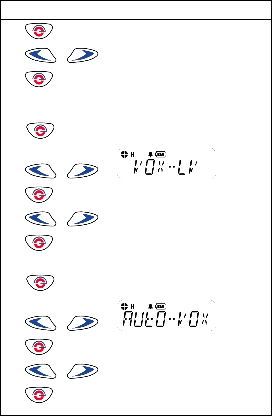
17. Vox Level
16 level is available..
1). to enter Menu Mode.
2) or to until
3) to select
4) or to scroll list
5) to select for exit
18. Auto Vox
1). to enter Menu Mode.
2) or to until
3) to select
4) or to select ON /OFF.
5) to select
1914 - 14 -1419
FILE: IM100 manual.doc 2004.11.23
E-TECH Co., Ltd 14/19
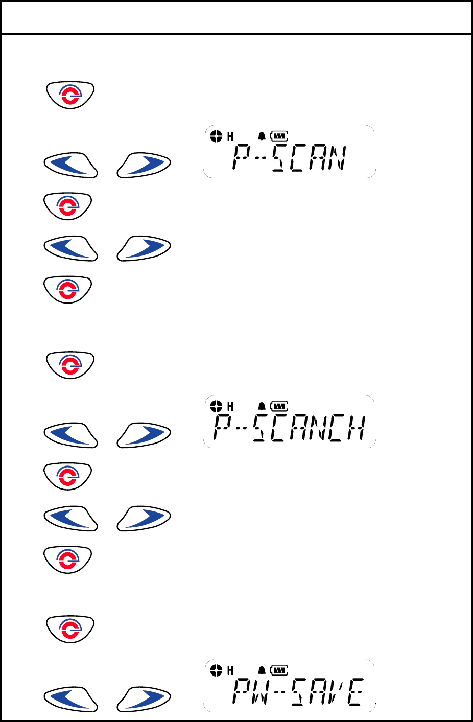
19. Priority Scan
1). to enter Menu Mode.
2) or to until
3) to select
4) or to select ON /OFF.
5) to select
20. Priority scan CH
1). to enter Menu Mode.
2) or to until
3) to select
4) or to scroll list
5) to select for exit
21. Power save
1). to enter Menu Mode.
2) or to until
1915 - 15 -1519
FILE: IM100 manual.doc 2004.11.23
E-TECH Co., Ltd 15/19
3) to select
4) or to select ON /OFF.
5) to select
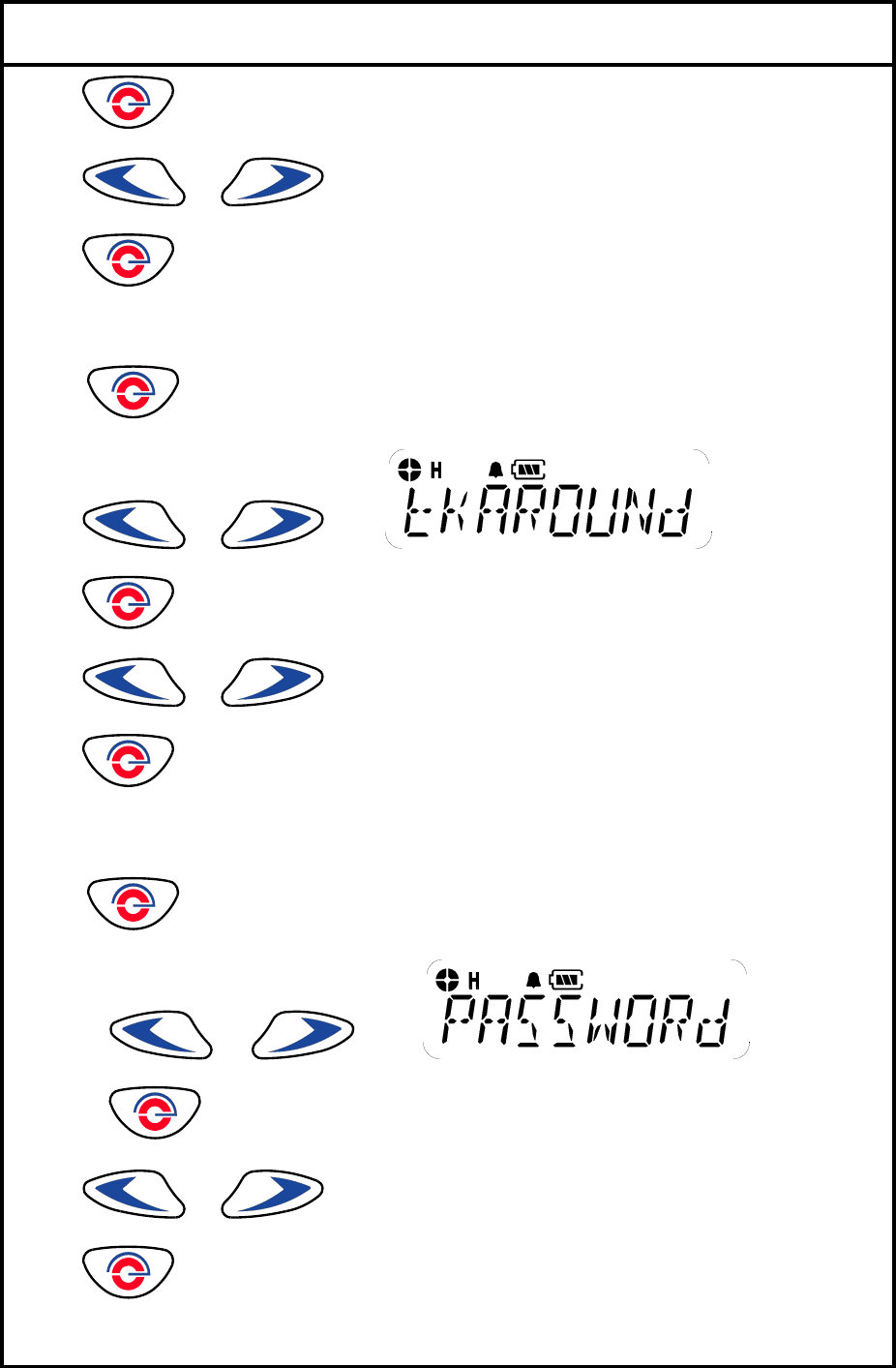
22. Talkaround
1). to enter Menu Mode.
2) or to until
3) to select
4) or to select ON /OFF.
5) to select
23. Password
1). to enter Menu Mode.
2) or to until
3) to select
4) or to select ON /OFF.
5) to select

1916 - 16 -1619
FILE: IM100 manual.doc 2004.11.23
E-TECH Co., Ltd 16/19
24. Password CH
1). to enter Menu Mode.
2) or to until
3) to select
4) ---- will display on the LCD( enter old password)
or by pushing up and down KEY to change password.
by pushing enter KEY to change digit of password.
5) Enter new password by 4 digit.
25. Location
Indicate where the radio is located by blinking green light every 7 seconds.
1). to enter Menu Mode.
2) or to until
3) to select
4) or to select ON /OFF.
5) to select
26. Scramble
1). to enter Menu Mode.
2) or to until

1917 - 17 -1719
FILE: IM100 manual.doc 2004.11.23
E-TECH Co., Ltd 17/19
3) to select
4) or to select ON /OFF.
5) to select
27. Status call Send
1). to enter Menu Mode.
2) or to until
3) to select
4) or to select ON /OFF.
5) to select
5. Antenna Installation
5-1 Antenna Installation and Compliance with Radio Frequency(RF) Energy Safety
Standards
[IMPORTANT NOTE]
To assure optimum performance and compliance with RF Energy Safety standards, this
antenna installation guidelines and Instructions are limited to metal-body vehicles with
appropriate ground planes and take into account the potential exposure of backseat
passengers and bystanders outside the vehicle.
[NOTE]
For mobile radios with rated power of 7 watts or less, the only installation restrictions are
to use only E-tech approved antennas and install the antenna externally on metal body
vehicles. For mobile radios with rated power greater than 7 watts, always adhere to all
the guidelines and restrictions in 5.2 below.

1918 - 18 -1819
FILE: IM100 manual.doc 2004.11.23
E-TECH Co., Ltd 18/19
5-2 Selecting an Antenna Site/Location on a Metal Body Vehicle
1. External installation – Check the requirements of the antenna supplier and install the vehicle
antenna external to a metal body vehicle in accordance with those requirements.
2. Roof top – For optimum performance and compliance with RF Energy Safety standards, mount
the antenna in the center area of the roof.
3. Trunk lid – On some vehicles with clearly defined, flat trunk lids, the antenna of some radio
models (see restrictions below) can also be mounted on the center area of the trunk lid. For
vehicles without clearly defined, flat trunk lids (such as hatchback autos, sport utility vehicles, and
pick-up trucks), mount the antenna in the center area of the roof.
Before installing an antenna on the trunk lid.
• Be sure that the distance from the antenna location on the trunk lid will be at least 60cm (24
inches) from the front surface of the rear seat-back to assure compliance with RF Energy Safety
standards.
• Ensure that the trunk lid is grounded by connecting grounding straps between the trunk lid and
the vehicle chassis.
If these conditions can not be satisfied, then mount the antenna on the roof top !
4. Mounting restrictions for certain radio models
For more than 40 Watt VHF models, the 1/4 wave antenna should be mounted only in the
center area of the roof, not on the trunk lid, to assure compliance with RF Energy Safety
standards.
5. Ensure that the antenna cable can be easily routed to the radio. Route the antenna cable as
far away as possible from any vehicle electronic control units and associated wiring.
6. Check the antenna location for any electrical interference.
7. Make sure any other mobile radio antenna on this vehicle is at least 30.48 cm (1 foot) away from
this antenna.
[NOTE]
Any two metal pieces rubbing against each other (such as seat springs, shift levers, trunk
and hood lids, exhaust pipes, etc.) in close proximity to the antenna can cause severe
receiver interference.

1919 - 19 -1919
FILE: IM100 manual.doc 2004.11.23
E-TECH Co., Ltd 19/19
5-3 Antenna Installation Procedure
1. Mount the antenna according to the instructions provided with the antenna kit. Run the coaxial
cable to the radio mounting location. If necessary, cut off the excess cable and install the cable
connector.
2. Connect the antenna cable connector to the radio antenna connector on the rear of the radio.
5-4 Completing the Installation
1. Mount the microphone clip to a convenient spot near your radio.
2. Your microphone has a telephone-type connector at the end of is cord. Plug the microphone
into the control head connector.
3. To complete your radio installation, plug the power cable into the radio power connector.