EA Technology UTP2A UltraTEV Plus2 User Manual EA Technology Report
EA Technology Limited UltraTEV Plus2 EA Technology Report
Contents
- 1. User manual
- 2. Users manual
- 3. User Manual
Users manual
UltraTEV Plus2 Operating Manual
Product Code: UTP2
Version: 8
Date: March 2018
EA Technology UltraTEV Plus2 Operating Manual 2388L018
Contents
FCC Warning Statement ........................................................................................................................................................... 1
IC Warning Statement ............................................................................................................................................................... 1
1. What does the UltraTEV Plus² do? ...................................................................................................................... 2
2. What’s in the Box? ........................................................................................................................................................ 3
3. Important Information .............................................................................................................................................. 4
4. Non-Intrusive Detection of Partial Discharge Activity ........................................................................... 5
4.1 What is Partial Discharge? ................................................................................................. 5
4.2 How can Partial Discharge be detected? .......................................................................... 5
4.3 Airborne Ultrasonic Discharge Activity ............................................................................ 5
4.4 Electromagnetic Discharge Activity .................................................................................. 6
4.5 Cable Partial Discharge Activity ........................................................................................ 6
5. Using the UltraTEV Plus² .......................................................................................................................................... 7
5.1 Charging the UltraTEV Plus2 .............................................................................................. 8
5.2 Turning the UltraTEV Plus² On/Off ................................................................................... 9
5.3 Self-Test .............................................................................................................................. 9
5.4 Notification Bar .................................................................................................................. 9
5.4.1 Temperature & Humidity ..................................................................................... 10
5.5 Menu Bar ........................................................................................................................... 11
5.6 Main Menu ........................................................................................................................ 12
5.7 TEV/Cable PD Menu ......................................................................................................... 13
5.7.1 Measure Screen .................................................................................................... 13
5.7.2 Phase Plot ............................................................................................................. 14
5.7.3 Waveform .............................................................................................................. 16
5.7.4 Histogram ............................................................................................................. 17
5.7.5 Interpretation ....................................................................................................... 18
5.8 Ultrasonic Screen ............................................................................................................. 20
5.8.1 Ultrasonic classification ....................................................................................... 21
5.9 Context Menu ................................................................................................................... 22
5.9.1 Audio output ........................................................................................................ 22
5.9.2 Filters .................................................................................................................... 23
5.9.3 Phase Reference ................................................................................................... 23
5.10 Settings Screen................................................................................................................. 26
5.10.1 System Settings .................................................................................................... 26
5.10.2 Measurement Settings ......................................................................................... 28
5.10.3 Wireless Settings .................................................................................................. 29
5.10.4 About .................................................................................................................... 30
5.10.5 In-field Firmware Upgrade ................................................................................... 31
5.10.6 Reset All Settings ................................................................................................. 33
5.11 File Browser ...................................................................................................................... 34
5.12 Screenshot ........................................................................................................................ 35
5.13 Function Check ................................................................................................................ 37
6. NFC Functionality ...................................................................................................................................................... 38
6.1 NFC Tag Installation ........................................................................................................ 38
6.2 Substation Tag ................................................................................................................. 39
6.3 Writing to a Substation Tag ............................................................................................ 39
6.4 Reading a Substation Tag ............................................................................................... 40
EA Technology UltraTEV Plus2 Operating Manual 2388L018
6.5 Asset Tag .......................................................................................................................... 40
6.6 Writing to an Asset Tag ................................................................................................... 41
6.7 Reading an Asset Tag ...................................................................................................... 42
6.8 Reading an NFC Tag from the Main Menu ..................................................................... 42
6.9 NFC Tag Trouble Shooting .............................................................................................. 43
7. Survey ............................................................................................................................................................................... 44
7.1 Create a Workflow using the Workflow Generator ........................................................ 44
7.2 Starting a Survey .............................................................................................................. 46
7.3 Select Workflow ................................................................................................................ 47
7.4 Skip Workflow .................................................................................................................. 49
7.5 Ad-hoc Measurement ....................................................................................................... 49
7.6 Survey Metadata Forms ................................................................................................... 49
7.7 Using Populated Lists ...................................................................................................... 52
7.8 Using the virtual keyboard .............................................................................................. 52
7.9 Background Measurements ............................................................................................. 53
7.10 Recording Data ................................................................................................................ 54
7.10.1 TEV recorded data ................................................................................................ 54
7.10.2 Cable PD recorded data ....................................................................................... 54
7.10.3 Ultrasonic recorded data ..................................................................................... 54
7.11 Viewing Survey Progress ................................................................................................. 55
7.12 Adding Media to a Survey ............................................................................................... 56
7.13 Completing a Survey ........................................................................................................ 56
8. Reviewing Results ..................................................................................................................................................... 57
8.1 Hotspot Connection ......................................................................................................... 57
8.2 Wi-Fi Connection .............................................................................................................. 58
8.3 USB Connection (Windows PC only) ................................................................................ 58
8.4 MicroSD Card & Data Zip Files ........................................................................................ 59
8.5 Data Analysis Screens ...................................................................................................... 59
8.5.1 TEV & Cable PD Analysis Screen ......................................................................... 60
8.5.2 Ultrasonic Analysis ............................................................................................... 62
9. Detecting Partial Discharge using the UltraTEV Plus² ........................................................................ 63
9.1 TEV Measurement ............................................................................................................ 63
9.1.1 Background Noise ................................................................................................ 63
9.1.2 Measuring TEV ..................................................................................................... 64
9.2 Cable PD Measurement ................................................................................................... 65
9.2.1 Practical RFCT Connection Requirements .......................................................... 65
9.2.2 Measuring PD in cables ....................................................................................... 65
9.3 Ultrasonic Measurement ................................................................................................. 66
9.3.1 Measuring Ultrasonic ........................................................................................... 66
9.3.2 Measuring Ultrasonic with the UltraDish............................................................ 67
9.3.3 Measuring Ultrasonic using the Flexible Sensor ................................................ 68
9.3.4 Ultrasonic Measurement using the Contact Probe Accessory .......................... 69
9.3.5 Using the Ultrasonic Contact Probe .................................................................... 70
9.3.6 Detection, Measurement and Localisation of the Partial Discharge ................ 71
9.3.7 Mounting Practices .............................................................................................. 71
9.3.8 Sources of Noise and Phantom Signals .............................................................. 73
10. UltraTEV Plus² Specification ............................................................................................................................... 74
TEV Measurements .......................................................................................................... 74
Ultrasonic Measurements ................................................................................................ 74
Cable PD Measurements .................................................................................................. 74
Hardware .......................................................................................................................... 75
EA Technology UltraTEV Plus2 Operating Manual 2388L018
Environmental .................................................................................................................. 75
Dimensions ...................................................................................................................... 75
Power Supplies ................................................................................................................. 75
Battery Charger ................................................................................................................ 76
11. Declaration of Conformity ................................................................................................................................... 77
12. Maintenance ................................................................................................................................................................. 78
13. Warranty Policy ........................................................................................................................................................... 78
14. Calibration ..................................................................................................................................................................... 79
15. Repair ............................................................................................................................................................................... 79
16. Waste Electrical and Electronic Equipment Directive (WEEE) .......................................................... 79
17. Continuous Improvement .................................................................................................................................... 79
18. Contact Us ..................................................................................................................................................................... 80
19. Record of Changes ................................................................................................................................................... 81
EA Technology UltraTEV Plus2 Operating Manual 2388L018
Page 1 of 82
FCC Warning Statement
· This device complies with Part 15 of the FCC Rules.
Operation is subject to the following two conditions:
(1) This device may not cause harmful interference, and
(2) This device must accept any interference received, including interference that may
cause undesired operation.
· This equipment complies with FCC radiation exposure limits set forth for an
uncontrolled environment. End users must follow the specific operating instructions for
satisfying RF exposure compliance. This transmitter must not be co-located or operating
in conjunction with any other antenna or transmitter.
· Changes or modifications not expressly approved by the party responsible for
compliance could void the user's authority to operate the equipment
IC Warning Statement
Under Industry Canada regulations, this radio transmitter may only operate using an
antenna of a type and maximum (or lesser) gain approved for the transmitter by Industry
Canada.
To reduce potential radio interference to other users, the antenna type and its gain should
be so chosen that the equivalent isotropically radiated power (e.i.r.p.) is not more than
that necessary for successful communication.
This device complies with Industry Canada licence-exempt RSS standard(s). Operation
is subject to the following two conditions: (1) this device may not cause interference,
and (2) this device must accept any interference, including interference that may cause
undesired operation of the device.
EA Technology UltraTEV Plus2 Operating Manual 2388L018
Page 2 of 82
1. What does the UltraTEV Plus² do?
The UltraTEV Plus² is a versatile hand-held tool used to easily detect and classify Partial
Discharge (PD) in a wide range of electrical equipment.
The UltraTEV Plus² uses inbuilt TEV and Ultrasonic sensors and external accessories to
detect the presence of potentially damaging PD in switchgear, cables and overhead line
equipment.
The UltraTEV Plus² brings together three complementary sensor modes in a single hand
held instrument by regularly checking switchgear while it’s in service. Using the UltraTEV
Plus2, failure risks can be identified and action taken to avoid faults and downtime.
Algorithms and analysis capability built in to the UltraTEV Plus² provide vital insight,
classifying what you find to support the decisions you make and deliver the outcomes you
need. It’s never been simpler to interpret what you’re seeing and choose a course of action.
The UltraTEV Plus² records measurements at the touch of a button. Internal storage can be
used to provide access to historical data while you’re out in the field. Capturing what you’ve
measured allows you to see trends in the performance of your network.
EA Technology UltraTEV Plus2 Operating Manual 2388L018
Page 3 of 82
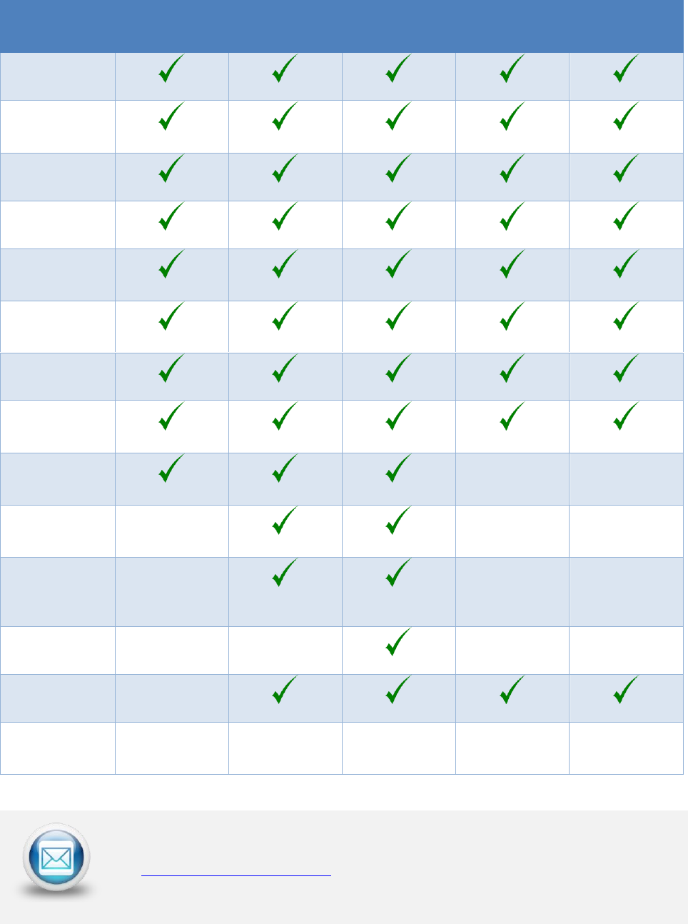
2. What’s in the Box?
Part
Kit 1
Kit 2
Kit 3
Kit 2
Upgrade
Kit 3
Upgrade
UltraTEV Plus2
Mains
Charger
Car Charger
USB Lead
8GB MicroSD
& SD adapter
Environmental
Sensor
Stylus x 2
NFC Starter
Pack
Neckband
Headphones
Ultrasonic
Contact Probe
Flexible
Microphone
Sensor
UltraDish
RFCT & Cable
Tough Carry
Case
X (T-Loc II)
X (T-Loc II)
X (T-Loc IV)
X (T-Loc II)
X (T-Loc IV)
For Spares and Accessories
For spares and accessories, please contact your local sales representative
or sales@eatechnology.com
EA Technology UltraTEV Plus2 Operating Manual 2388L018
Page 4 of 82
3. Important Information
• The UltraTEV Plus2 is designed for use at ground potential only.
• When testing electrical plant ensure that the metalwork is earthed
before taking any measurements.
• Maintain safety clearances between structures at high voltage and
the instrument, its probes and the operator at all times.
• RFCTs, connecting leads and test equipment do not provide
protection against high voltage.
• Under no circumstances are earth/ground connections to be
loosened, disconnected or otherwise altered to allow use of this
equipment.
• Adhere strictly to local safety procedures.
• Do not make measurements when there are electrical storms in the
vicinity.
• Do not make measurements immediately following the energisation
of a circuit.
• Do not disturb plant during measurements either mechanically (e.g.
by shaking or striking it), electrically (e.g. by increasing the voltage)
or physically (e.g. by applying heat).
• Do not operate the instrument or its accessories in an explosive
atmosphere.
• Mains supply voltages are present within the battery charger.
• This unit contains no user serviceable parts, always return to EA
Technology or your local distributor for service and repair.
• Care must be taken where work is performed in tight corners, where
the proximity of other earth planes will affect the reading. If
possible maintain a distance of more than 30cm from metal work
which runs perpendicular to the sensor faceplate.
For application information please contact:
product-support@eatechnology.com
EA Technology UltraTEV Plus2 Operating Manual 2388L018
Page 5 of 82
4. Non-Intrusive Detection of Partial Discharge
Activity
4.1 What is Partial Discharge?
Partial discharges are electrical discharges that do not completely bridge the insulation
between electrodes. The magnitude of these discharges is usually small, however they
cause progressive deterioration of insulation that may eventually lead to failure.
Non-intrusive partial discharge detection provides a means for identifying these potential
sources of insulation failure. If not detected the discharge may result in failure causing not
only in loss of supply to customers and damage to plant but could also endanger staff.
4.2 How can Partial Discharge be detected?
A partial discharge emits energy in various ways and produces a number of effects which
can be detected:
Electromagnetic:
• Radio
• Light
• Heat
Acoustic:
• Audio
• Ultrasonic
Gases:
• Ozone
• Nitrous oxides
The most practical techniques for non-intrusive testing are based on the detection of the
radio frequency part of the electromagnetic spectrum and ultrasonic emissions. The
UltraTEV Plus2 has specifically been developed to enable electromagnetic and ultrasonic
activity to be detected in a single simple to use instrument.
4.3 Airborne Ultrasonic Discharge Activity
Acoustic emissions from partial discharge activity occur over the whole acoustic spectrum.
Audible detection is possible but depends on the hearing ability of the individual. Using
an instrument to detect the ultrasonic part of the acoustic spectrum has several
advantages; instruments are more sensitive than the human ear, are not operator
dependent and are more directional when operating above the audible frequency.
EA Technology UltraTEV Plus2 Operating Manual 2388L018
Page 6 of 82
The most sensitive method of detection is using an airborne ultrasonic Microphone centred
at 40 kHz. This method is very successful at detecting partial discharge activity provided
there is an air passage between the source and the Microphone.
4.4 Electromagnetic Discharge Activity
When partial discharge activity occurs within high voltage switchgear, it generates
electromagnetic waves in the radio frequency range which can only escape from the inside
of the switchgear through openings in the metal casing. These openings may be air gaps
around covers, or gaskets, or other insulating components. When the electromagnetic
wave propagates outside the switchgear, it produces a Transient Earth Voltage (TEV) on the
metal casing of the switchgear. The Transient Earth Voltage (TEV) is only a few millivolts,
of short duration having a rise time of a few nanoseconds and can be detected non-
intrusively by placing a TEV probe on the outside of the earthed switchgear whilst the
switchgear is in service.
4.5 Cable Partial Discharge Activity
When a partial discharge event occurs in a cable, there will be a resulting current pulse
coupled onto the earthed sheath of the cable. These pulses will propagate away from the
discharge site in both directions. Once the pulse reaches a change in impedance at a cable
joint or termination, a partial reflection occurs. This results in the pulses travelling back
down the cable several times (depending on the cable length) as they decay away. The
current pulses can be detected non-intrusively using a Radio Frequency Current
Transformer (RFCT) sensor placed around the cable earth strap.
EA Technology UltraTEV Plus2 Operating Manual 2388L018
Page 7 of 82
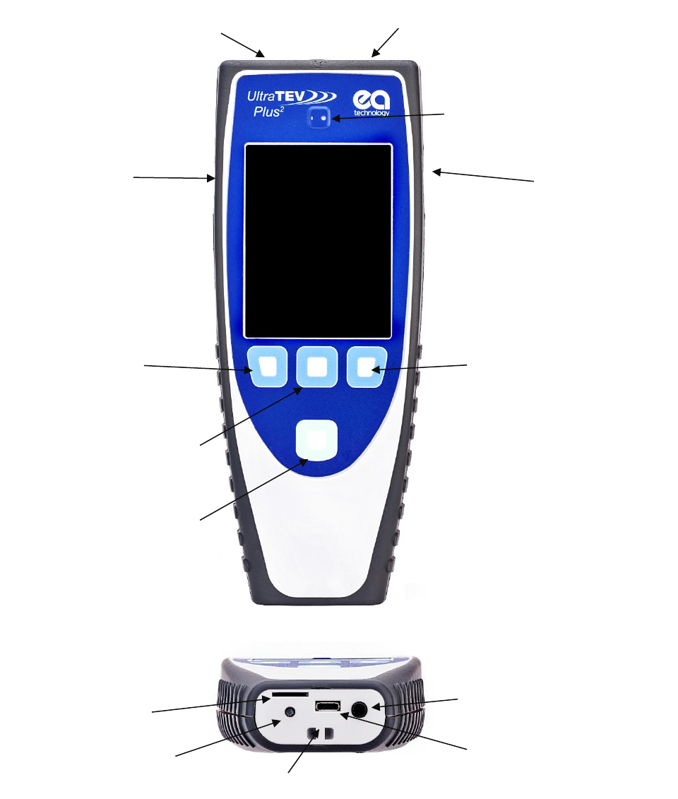
5. Using the UltraTEV Plus²
Smart
Accessory
Port
Right Button
Middle Button
Left Button
Home Button
Photo Sensor
microSD card slot
LED charging indicator
Audio out/headphone
socket
Ultrasonic
Accessory Port
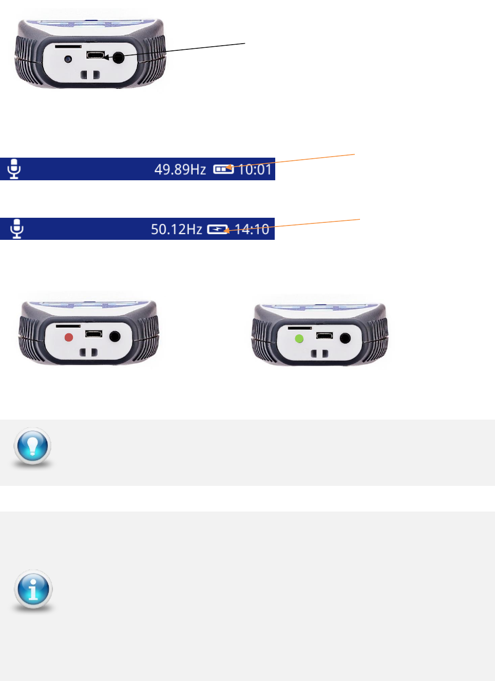
Micro USB charging port
Ultrasonic Microphone
TEV sensor
Lanyard loop
EA Technology UltraTEV Plus2 Operating Manual 2388L018
Page 8 of 82
5.1 Charging the UltraTEV Plus2
UltraTEV Plus² is charging
UltraTEV Plus² is fully charged
For the quickest charging time, turn off the UltraTEV Plus2 instrument
during charging. Charging time is extended when connected to a USB port
compared to the mains charger.
The TEV/Cable PD and Ultrasonic measuring features are automatically
disabled when the instrument is being charged.
A fully-charged battery should provide approximately 6 hours of continuous
use while switched on and measuring. For practical purposes, a fully
charged battery should last a full day of surveying.
The UltraTEV Plus² needs to have sufficient charge to remain powered on
while viewing data through a USB port.
A laptop USB port may not provide enough power to charge the UltraTEV
Plus² and view data simultaneously.
Micro USB charging port
Use the supplied USB cable to charge the
UltraTEV Plus² with the mains charger,
in-car charger or from a standard USB
port.
Battery Level
Indicator
Charging

EA Technology UltraTEV Plus2 Operating Manual 2388L018
Page 9 of 82
5.2 Turning the UltraTEV Plus² On/Off
Power on press and hold for 1 second
Power off press and hold for 2 seconds
5.3 Self-Test
During power up the UltraTEV Plus2 performs a self-test on TEV, ultrasonic and Cable PD
using the inbuilt test sources. The self-test is not a calibration check.
If self-test consistently fails, contact Product-support@eatechnology.com
5.4 Notification Bar
Below are other icons that could appear on the notification bar:
This icon indicates that the current audio source is TEV
This icon indicates that the current audio source is Ultrasonic
This icon indicates that the current audio source is the RFCT
This icon shows when a UltraDish has been connected to the UltraTEV Plus²
This icon shows when a RFCT has been connected to the UltraTEV Plus²
Battery Level
Indicator
Temperature &
Relative Humidity
Audio
Source
Time
Phase
Reference
EA Technology UltraTEV Plus2 Operating Manual 2388L018
Page 10 of 82
This icon shows when a Contact Probe has been connected to the UltraTEV Plus²
This icon shows when a Flexible Sensor has been connected to the UltraTEV Plus
This icon shows when the UltraTEV Plus² is charging
This icon is used to show when a Wi-Fi connection has been established
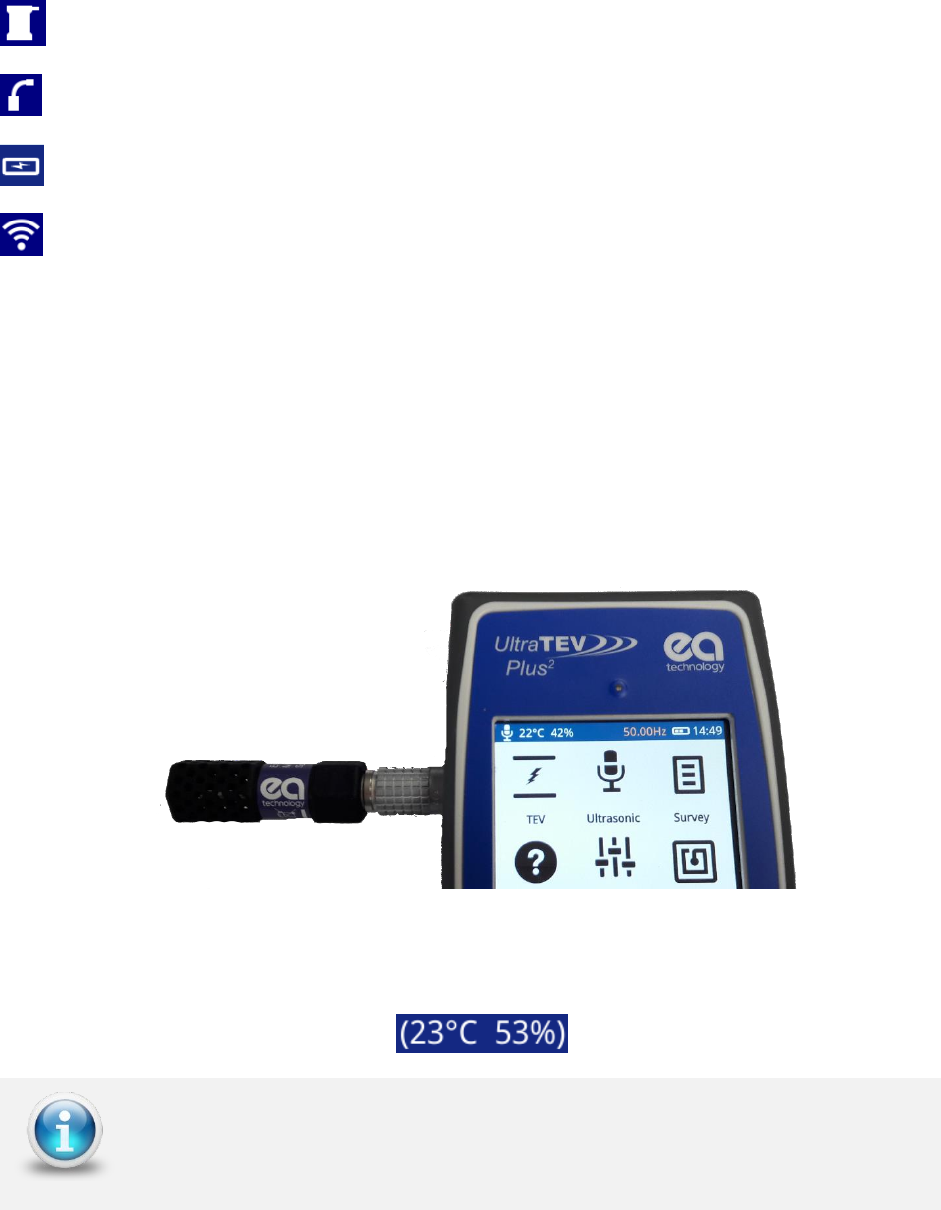
5.4.1 Temperature & Humidity
The temperature and relative humidity reading is displayed on the notification bar only
after connection of the Environmental Sensor.
The Environmental Sensor pictured below is connected to the Smart Accessory Port on the
left hand side of the instrument. The connection of the accessory automatically starts the
data collection with the latest reading being displayed in the notification bar at the top left
of the screen.
In order to allow use of other optional accessories whilst still displaying a reference
temperature, the final reading on removal of the sensor is persisted. Additional brackets
around the measurement demonstrate that this is a historic reading.
Wait for the temperature and humidity reading to settle. This may take a
while if it has been stored in very high or low temperatures.

EA Technology UltraTEV Plus2 Operating Manual 2388L018
Page 11 of 82
5.5 Menu Bar
The menu bar is located at the bottom of the screen. It displays icons that correlate to the
Left, Middle and Right Buttons. The icons on the Menu bar change depending on which
mode the UltraTEV Plus2 is in.
The Left button , Middle Button and Right Button can be pressed
to select the Main menu buttons respectively
EA Technology UltraTEV Plus2 Operating Manual 2388L018
Page 12 of 82
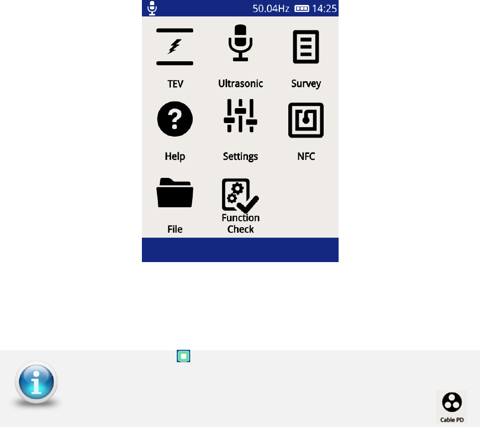
5.6 Main Menu
After powering up, the UltraTEV Plus2 will load up to the Main Menu as shown below.
The Home Button can be used to navigate back to the Main Menu at any
time.
The TEV icon on the main screen will change to a Cable PD icon
when a RFCT accessory is plugged in.
EA Technology UltraTEV Plus2 Operating Manual 2388L018
Page 13 of 82
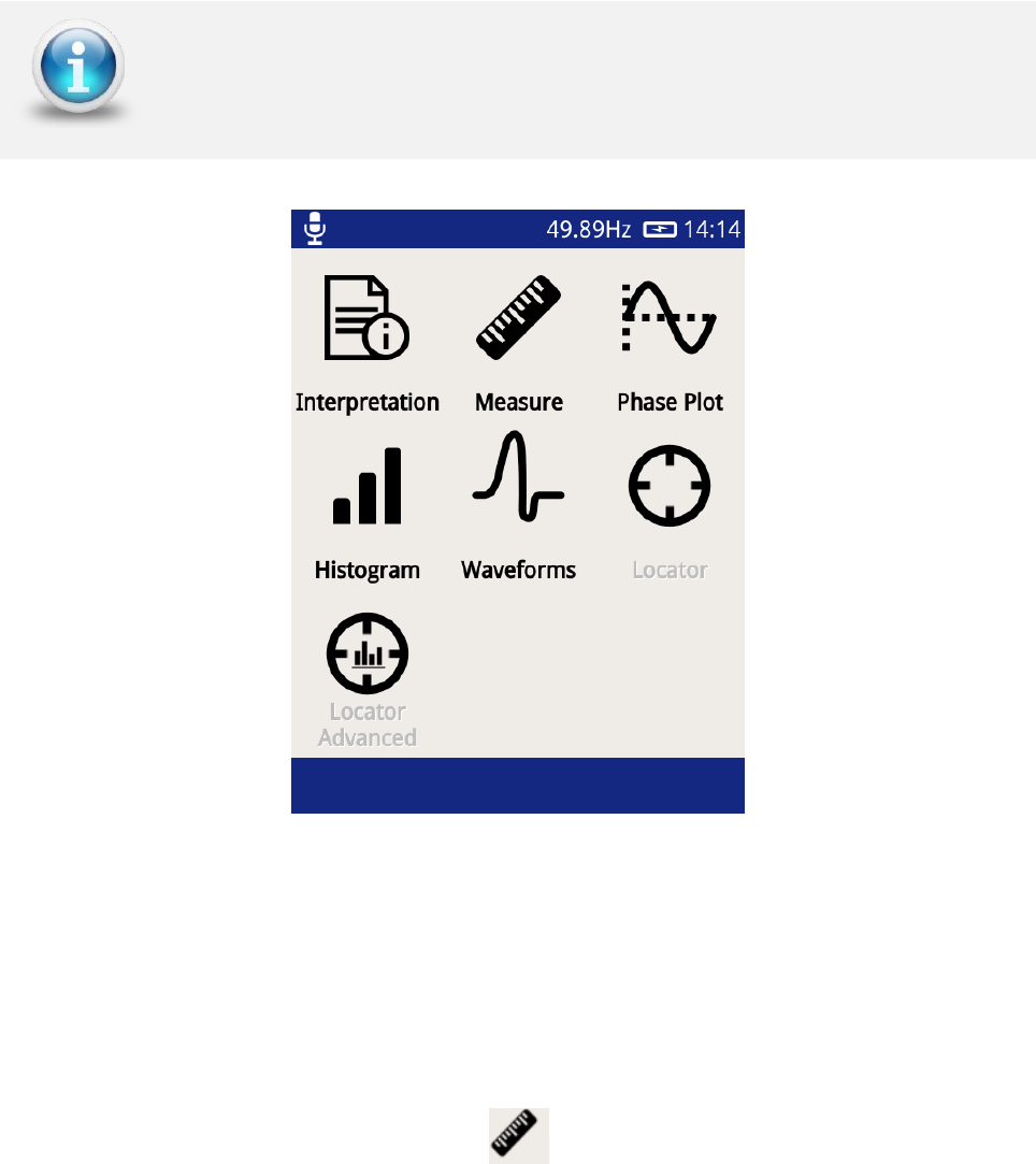
5.7 TEV/Cable PD Menu
The TEV/Cable PD screen, selected via the top left icon on the Main Menu contains different
modes which can be used for the PD measurement. The locator modes require additional
locator probe accessory.
The Interpretation option is only applicable when in TEV mode
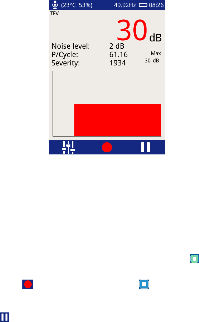
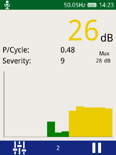
5.7.1 Measure Screen
The Measure mode is common to both TEV and Cable PD. This mode displays TEV readings
in dBmV (dB) or (if the RFCT accessory is connected) Cable PD readings in picoCoulombs
(pC).
To enter this mode, click the Measure icon .
EA Technology UltraTEV Plus2 Operating Manual 2388L018
Page 14 of 82
• P/Cycle – Shows the pulses per cycle based on either a 50 or 60Hz mains
frequency.
• Severity – Shows the short term severity (calculated by multiplying TEV magnitude
(mV) by Pulses Per Cycle). When in Cable PD mode, this is calculated by Charge
(pC) multiplied by Pulses Per Cycle.
• Max dB – displays the maximum dB value registered by the UltraTEV Plus2 since the
screen was entered or paused/reset. This value is displayed in pC.
• Chart - The bar chart is used to show the amplitude of the current values being
read by the UltraTEV Plus2, from right to left.
• Noise Level – This displays the amplitude in dB of the background noise level.
To exit the TEV screen back to the main menu, press the Home button .
There is an option to record a reading, this can be done by either clicking the red record
icon on the screen or by pressing the Middle button . All recordings are stored within
a ‘survey’ detailed in a later section of this manual.
Pausing a reading can also be achieved by either presing the Right button or clicking on
the ‘Pause’ icon. Audio output is also muted during a pause operation. After pausing
the screen the measurment can be restarted by pressing the restart button.
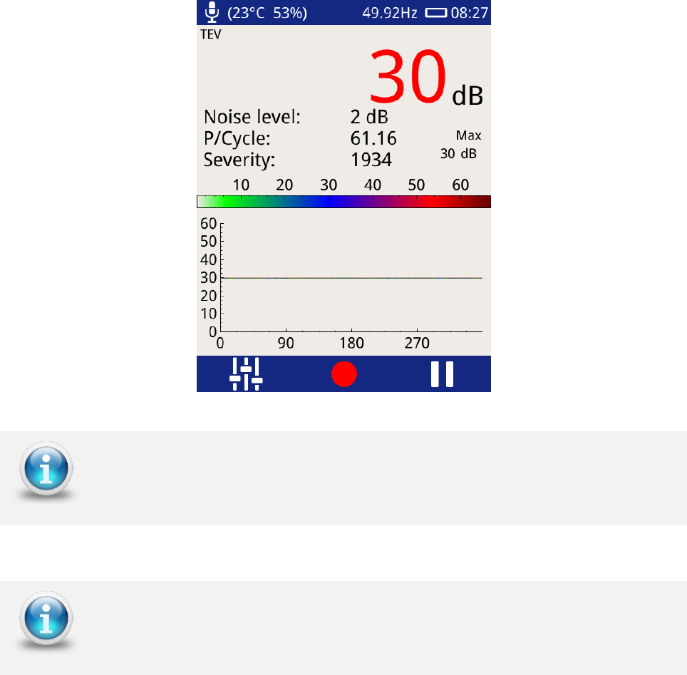
5.7.2 Phase Plot
The Phase Plot mode is common to both TEV and Cable PD. The upper section of the screen
shows measurement values as detailed previously under the ‘Measure Screen’. The lower
section contains a phase resolved intensity plot ‘Phase Plot’ of the measured activity.
The plot displays either TEV or Cable PD events’ phase angles (x-axis) against their
amplitude (y-axis). The colour scale represents the intensity (pulse count) at a given phase
angle and amplitude.
EA Technology UltraTEV Plus2 Operating Manual 2388L018
Page 15 of 82
This option is useful for distinguishing between whether a measured PD activity is a
genuine discharge source or just noise. For example, genuine PD activity may manifest
itself as a stable phase resolved plot which will occur at the same position with respect to
phase angle cycle by cycle; whilst white noise will not be phase related occurring at irregular
positions on the phase plot.
The Pause and Record option is also available in this mode; Severity, Noise
Level and P/Cycle are calculated as described under the Measure Screen
To zoom in on a chart, slide your finger from bottom left to top right of the
area of interest. To zoom out draw a diagonal line from top right to bottom
left.
EA Technology UltraTEV Plus2 Operating Manual 2388L018
Page 16 of 82
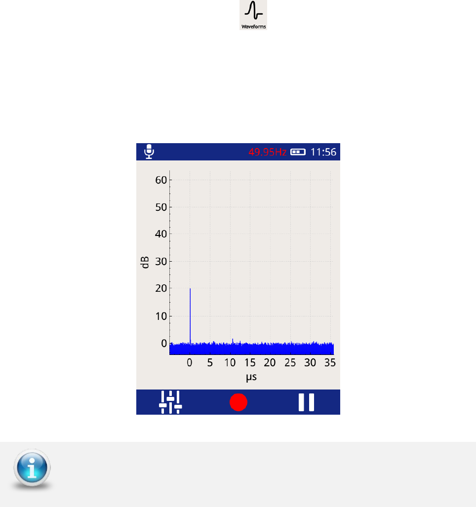
5.7.3 Waveform
The ‘Waveform’ mode is common to both TEV and Cable PD. When in Cable PD mode, values
will be displayed in mA, whilst in TEV mode they will be measured in dBmV as below.
To enter this mode, click the Waveform icon .
This mode displays a plot of a TEV or Cable PD activity as a function of time allowing an
instantaneous view of an activity’s amplitude with respect to time. This option can be used
to assist in distinguishing between genuine PD activity and noise. A Partial Discharge pulse
will normally manifest as a sharp fast rising edge pulse whilst noise is often slower and
less repeatable.
The Pause and Record option is also available in this mode as described
under the Measure Screen
EA Technology UltraTEV Plus2 Operating Manual 2388L018
Page 17 of 82
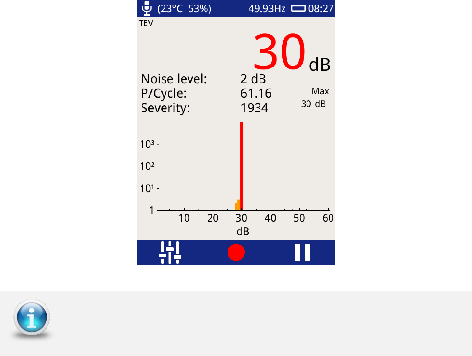
5.7.4 Histogram
This option (shown below) displays the number of events registered (y-axis) for a given
amplitude (x-axis). This measurement option is useful for determining if more than one
discharge source is present; two distinct groups of bars on this chart could mean there are
two sources of discharge at the respective dB (or pC) levels. The screen is also useful in
positively identifying a genuine source of PD and assessing its pulse rate when there is a
high pulse rate noise floor affecting the standard pulse per cycle calculation.
The Pause and Record option is also available in this mode; Severity, Noise
level and P/Cycle are calculated and as described under the Measure Screen
EA Technology UltraTEV Plus2 Operating Manual 2388L018
Page 18 of 82
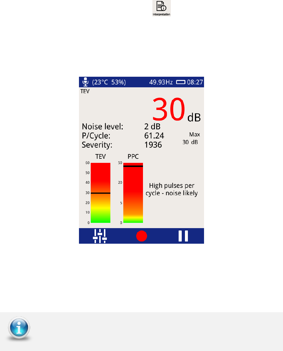
5.7.5 Interpretation
The ‘Interpretation’ mode available for TEV readings only.
To enter this mode, click the Interpretation icon .
The interpretation screen provides a first pass summary of the switchgear’s condition by
taking into account both the magnitude and repetition rate of any detected pulses. The
guide distinguishes between noise, surface tracking and internal discharge providing an
indication of the suggested action.
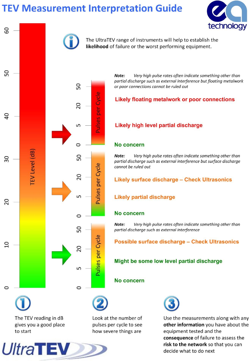
This display is an easy to use software implementation of the TEV measurement
interpretation guide produced by EA Technology using decades of experience. The original
summary document giving an overview of the original guidelines for the interpretation of
TEV measurements is included on the next page.
The Interpretation screen is only available when in TEV mode
EA Technology UltraTEV Plus2 Operating Manual 2388L018
Page 19 of 82
EA Technology UltraTEV Plus2 Operating Manual 2388L018
Page 20 of 82
5.8 Ultrasonic Screen
The Ultrasonic screen shows measurements taken using either the inbuilt Ultrasonic sensor
or the external Ultrasonic sensors (Contact Probe, Flexible Sensor or UltraDish) if
connected.
Ultrasonic magnitude is measured in dBµV and is displayed on the chart as phase angle (x-
axis) against amplitude (y-axis). The colour chart represents a key to show the intensity
(pulse count) at a given amplitude and phase angle.
This phase resolved plot can be used to further confirm the presence of a partial discharge
activity. In general PD activity will be displayed as a stable area which will occur at the same
to phase angle each cycle; whilst noise tends to be out of phase and occurs at irregular
positions on the phase plot.
The Pause and Record option is also available in this mode as described
under the Measure Screen
EA Technology UltraTEV Plus2 Operating Manual 2388L018
Page 21 of 82
5.8.1 Ultrasonic classification
The Ultrasonic display on the UltraTEV Plus² includes the output of EA Technology’s
proprietary ultrasonic classification algorithm. The algorithm processes measured
ultrasonic data in real time to give an indication whether the input data is a background
noise source or partial discharge activity.
The algorithm processes the data from the ultrasonic Microphone along with the phase
reference signal, and looks for patterns within the data stream which experts at EA
Technology have identified as typical indicators of partial discharge.
The ultrasonic classification will not be displayed if the phase lock has not
been achieved.
EA Technology UltraTEV Plus2 Operating Manual 2388L018
Page 22 of 82
5.9 Context Menu
Pressing the Left Button whilst in TEV, Cable PD or Ultrasonic modes brings up the Context
Menu as shown below. The Context Menu consists of a number of items with only those
relevant to the current mode of operation visible at any time. This mode allows commonly
used settings to be modified from within the measurement screen.
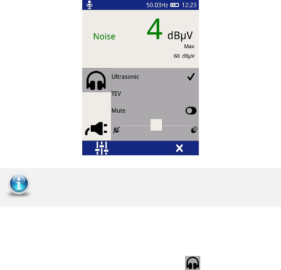
5.9.1 Audio output
The UltraTEV Plus² allows audio output of either Ultrasonic, TEV or Cable PD (dependent on
whether RFCT is connected or not) activity through the connection of external headphones.
The audio context menu allows control of the headphone output.
To modify the current audio settings click on the Audio icon . Within this sub menu the
audio output (TEV, Cable PD or Ultrasonic) can be selected, note this selection will persist
across modes.
To turn off the audio output toggle the Mute Button, the toggle icon will turn green to
indicate the Mute mode has been activated.
The volume of the audio output can also be modified by adjusting the slider to the desired
level as shown above.
The Context Menu contents is context specific; its contents will differ for
each measurement mode
EA Technology UltraTEV Plus2 Operating Manual 2388L018
Page 23 of 82
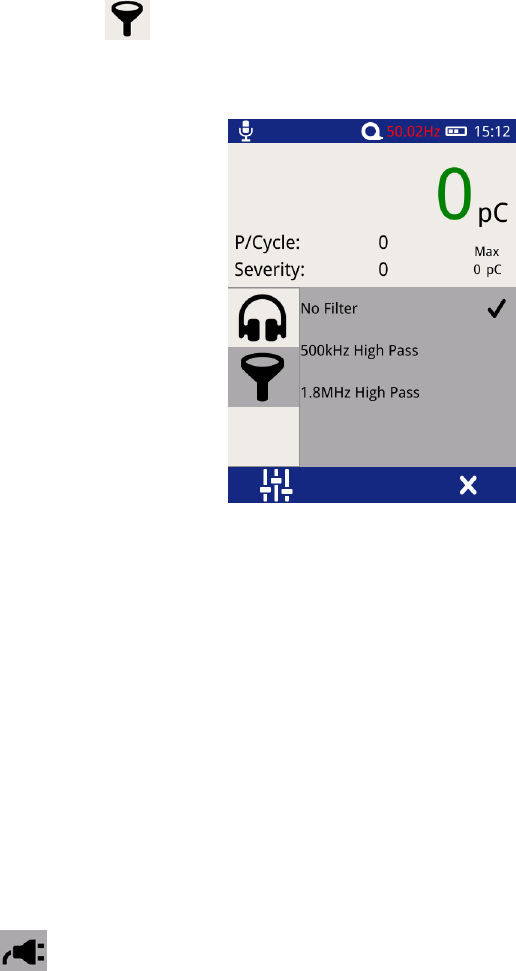
5.9.2 Filters
Select the filter icon to change the filter properties; this option is only enabled when
in Cable PD Measurement Mode and enables noise to be filtered from the cable PD
measurement.
Select the desired filter properties, a tick should appear when a selection has been (shown
above).
• No Filter – This option passes all frequency types.
• 500 kHz High Pass – This option activates a high pass filter that passes all
frequencies from 500kHz and above.
• 1.8 MHz High Pass – This option activates a high pass filter that passes all
frequencies from 1.8 MHz and above.
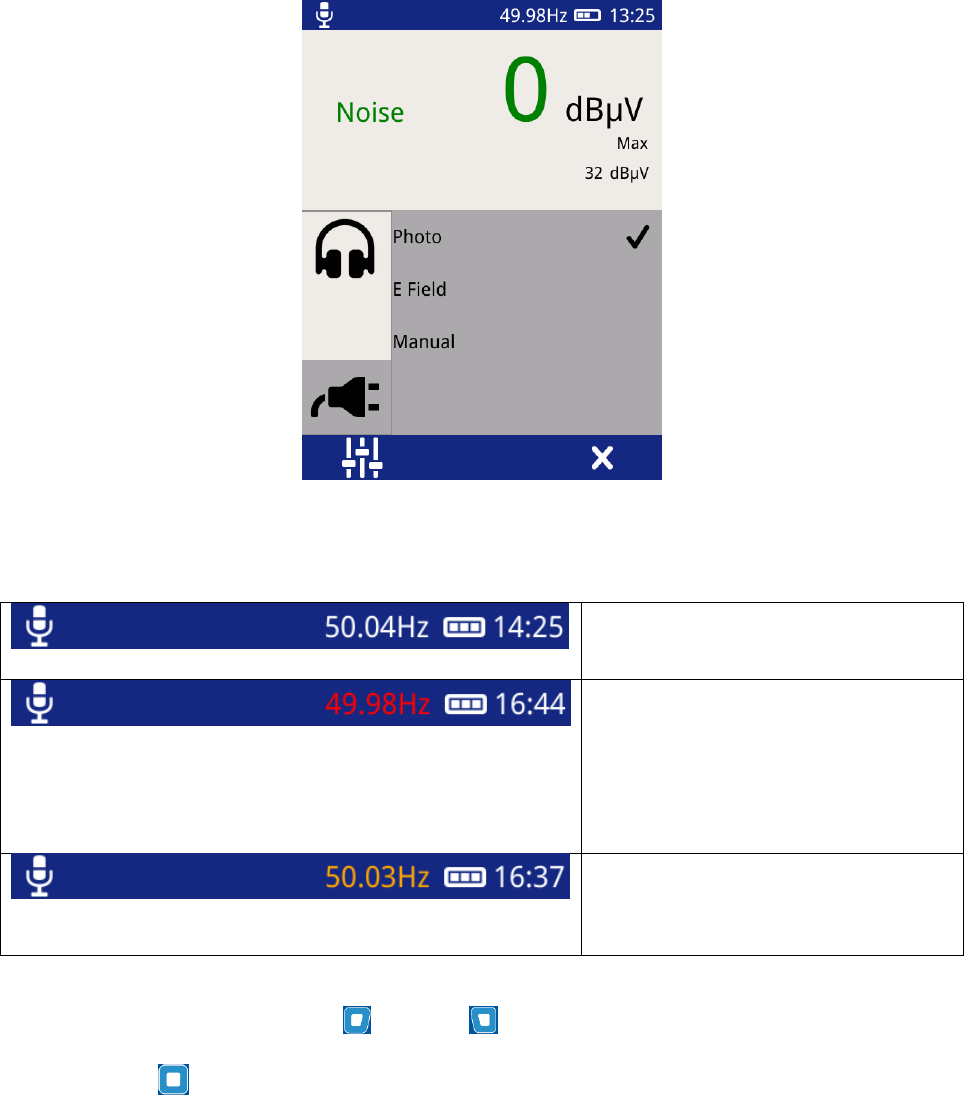
5.9.3 Phase Reference
Select the icon on the context menu to access the phase reference settings page. This
allows the source of the phase reference for the UltraTEV Plus² to be selected from the
following options:
• Photo – This option selects the Photo-sensor located on the front upper section of
the UltraTEV Plus² as the source of the Phase reference. The Photo-sensor requires
line of sight to a mains frequency light source such as a fluorescent fitting.
• E field – This option selects the in-built E-field sensor as the source of Phase
reference. The sensor detects the phase reference from the stray electric field
within the substation.
• Manual – Allows the user to manually adjust the phase reference.
EA Technology UltraTEV Plus2 Operating Manual 2388L018
Page 24 of 82
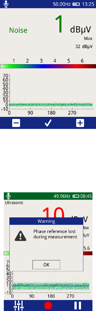
The current status of the phase reference is indicated by the colour of the phase readout.
A white phase display indicates a
phase lock has been achieved.
A red phase display indicates that
a phase lock has not been
achieved. A continous red phase
display would neccesitate the
change of mode.
An amber phase display indicates
that the frequency has been set
manually.
When in Manual Mode the Right and Left buttons can be used to increase or decrease
the phase reference respectively. Once the desired value has been reached, press the
middle button to store as shown below.
EA Technology UltraTEV Plus2 Operating Manual 2388L018
Page 25 of 82
During a data capture the UltraTEV Plus² monitors the phase lock to ensure a continuous
sync is achieved. If the phase lock is lost at any time during a capture the unit displays a
warning message on completion of the recording. Every attempt should be made to ensure
a phase lock is present as the lack of this may affect the analysis of the data captured.
EA Technology UltraTEV Plus2 Operating Manual 2388L018
Page 26 of 82
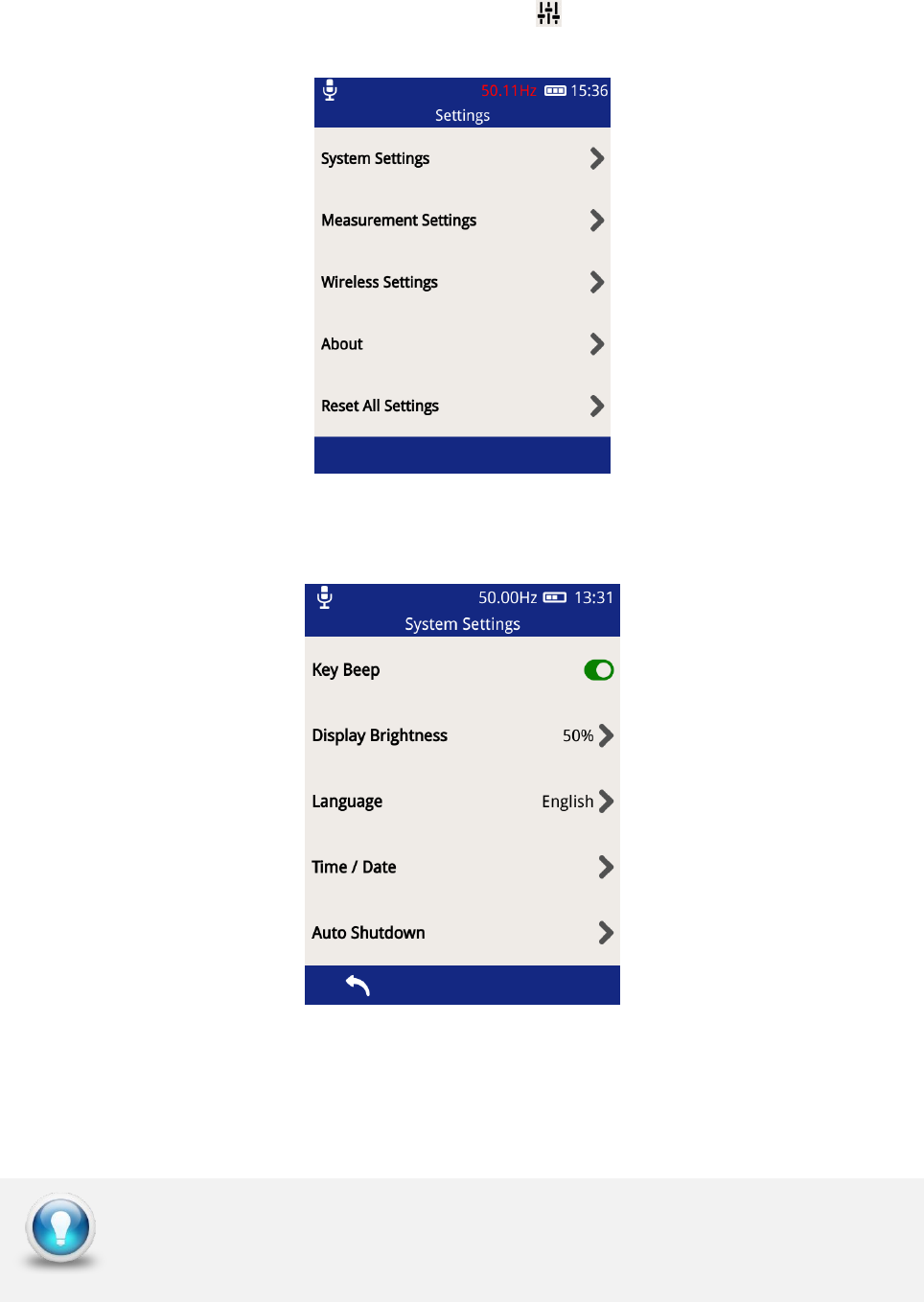
5.10 Settings Screen
To access the settings page, click the Settings icon on the Main Menu and the screen
shown below will be displayed.
5.10.1 System Settings
• Key Beep – allows the turning ON/OFF of the audible beeps when any of the
buttons are pressed and when a NFC tag is detected. The button toggles to a green
colour when Key Beep is activated.
• Display Brightness – click on this to change the intensity of the backlight.
Keeping the backlight to a minimal level will improve battery life
EA Technology UltraTEV Plus2 Operating Manual 2388L018
Page 27 of 82
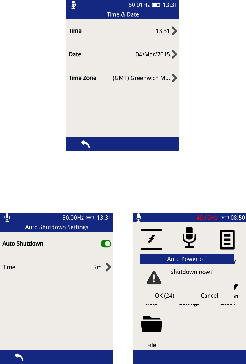
• Language – select this option to change the UltraTEV Plus² display language.
• Time/Date – select this option to change the Time and Date settings on the
UltraTEV Plus². The time zone can also be changed here as shown below.
• Auto Shutdown – this option can be used to Enable/Disable the Auto shutdown
feature of the UltraTEV Plus². After a defined period of push button inactivity, the
UltraTEV Plus² will display a warning message and then proceed to shut itself down
to conserve power. The inactivity period can also be changed here as shown below.
EA Technology UltraTEV Plus2 Operating Manual 2388L018
Page 28 of 82
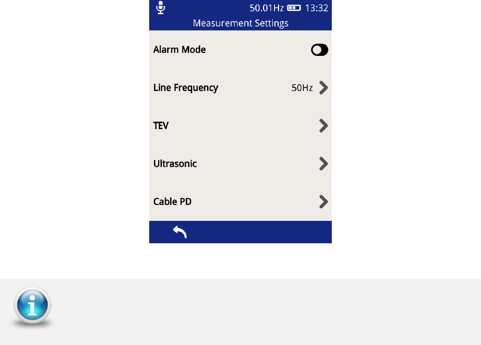
5.10.2 Measurement Settings
The Alarm Mode can be toggled on and off in this option. When the Alarm mode is activated,
the inbuilt beeper of the UltraTEV Plus² will be activated whenever the set Red threshold
level has been exceeded. In addition to this, threshold levels (Red and Amber levels) for the
various measurement features of the UltraTEV Plus² can be modified here together with the
line frequency.
The Ultrasonic only contains a Red Level threshold setting
EA Technology UltraTEV Plus2 Operating Manual 2388L018
Page 29 of 82
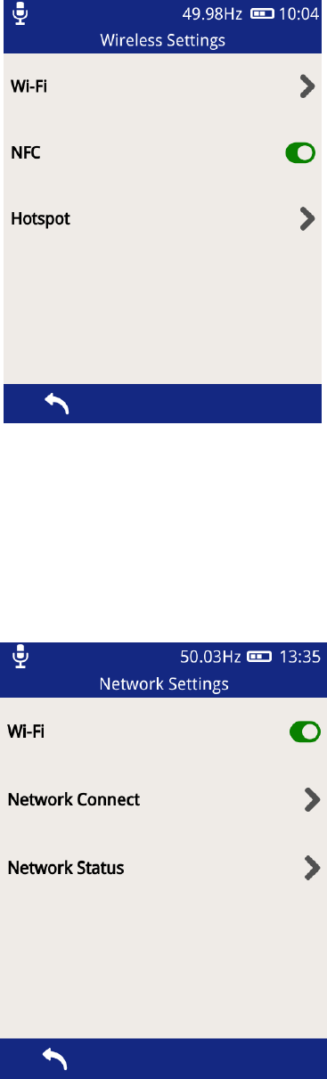
5.10.3 Wireless Settings
This section allows the setting of the Wi-Fi & NFC features of the UltraTEV Plus².
The NFC is enabled system wide by sliding the toggle switch to green. Once active the NFC
features can be accessed through the survey and measurement screens.
EA Technology UltraTEV Plus2 Operating Manual 2388L018
Page 30 of 82
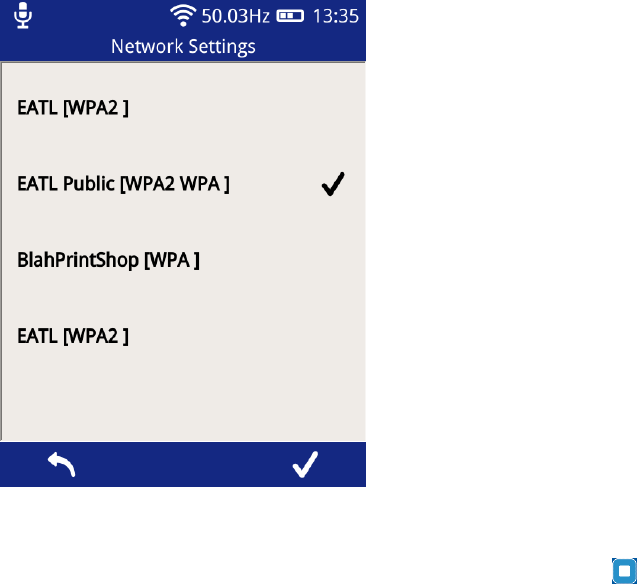
The Wi-Fi functionality can be switched on/off using the toggle button shown above. Select
‘Network Connect’ above to connect it to a Wi-Fi network.
Using the on-screen keyboard, enter the Wi-Fi password and then the Middle Button to
save the network.
The connection status of the UltraTEV Plus² can be viewed by selecting ‘Network Status’.
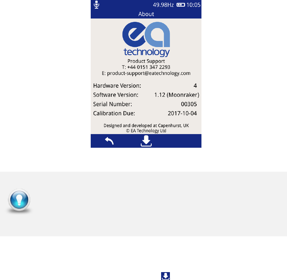
5.10.4 About
The about screen displays a summary of the UltraTEV Plus² components including both
hardware and software version numbers. The display also provides details of EA
Technology’s dedicated Product Support team should any further information be required.
EA Technology UltraTEV Plus2 Operating Manual 2388L018
Page 31 of 82
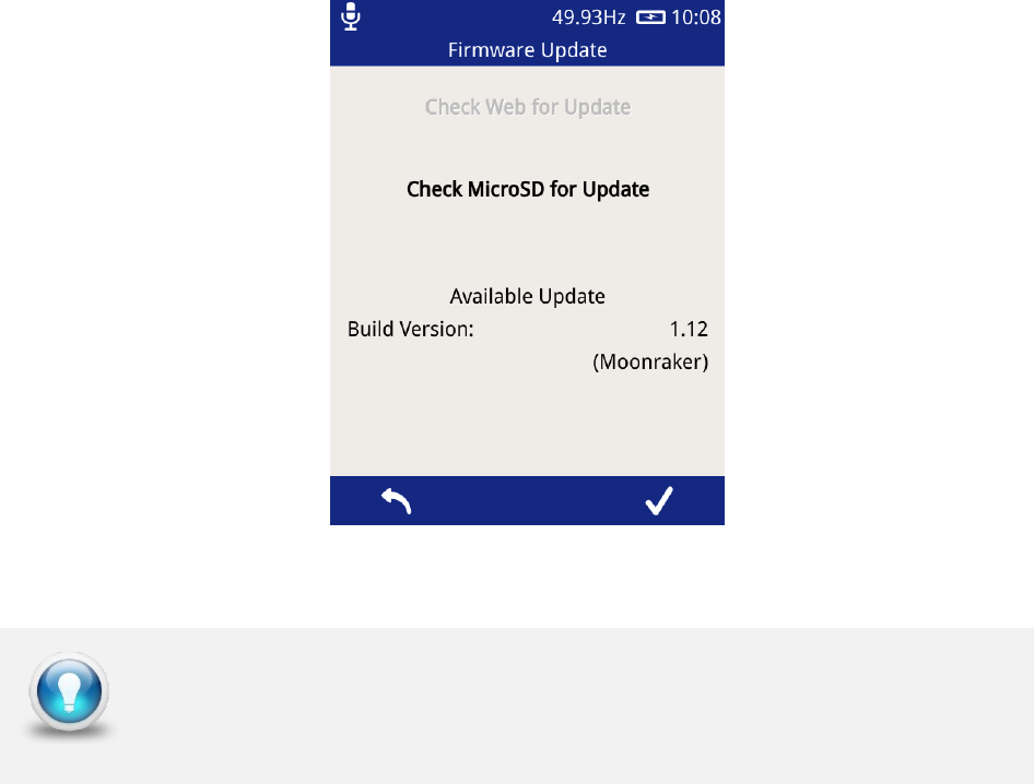
5.10.5 In-field Firmware Upgrade
Through the ‘About’ screen, the firmware of the UltraTEV Plus² can be updated. To access
the firmware update screen press the update icon .
The UltraTEV Plus² can be updated in the field from an update file loaded onto the MicroSD
card. Please check with Product Support for any available update files. To use this feature
the image will initially need to be copied from the distribution media to the ‘updates’ folder
on the MicroSD card. An SD to MicroSD adapter is supplied for use with laptops or PCs
which have an in built SD card reader.
To install a firmware update from the MicroSD card, press the “Check MicroSD for Update”
button on the above screen. The MicroSD card will be checked for any available updates,
and details populated on the display as shown below. To install the update found, press
the tick icon on the right of the menu bar and await the process to complete.
An update can only be installed if the instrument is plugged into the mains charger to avoid
any unwanted shutdown due to low battery whilst performing the update process. Once
installed, the instrument must be restarted to run the latest update.
To book the UltraTEV Plus² in for calibration ahead of its recommended
due date, please contact Product support :
Email: product-support@eatechnology.com
Tel: +44 (0)151 347 2293
EA Technology UltraTEV Plus2 Operating Manual 2388L018
Page 32 of 82
To check you have the most current software version or if you need
assistance in updating your instrument, please contact product support
EA Technology UltraTEV Plus2 Operating Manual 2388L018
Page 33 of 82
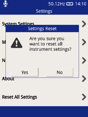
5.10.6 Reset All Settings
This option can be used to reset the UltraTEV Plus² back to the default settings. Upon
pressing the option a notification will appear asking for the action to be confirmed.
Once confirmed the follow settings will be reset back to their default state:
• Key Beep Enable
• Display Brightness
• Language
• Auto Shutdown Enable
• Auto Shutdown Time
• Line Frequency
• TEV Red and Amber Measurement Thresholds
• Ultrasonic Red Threshold
• Cable PD Thresholds
• Wi-Fi enable
Any Wi-Fi networks previously connected to and their login credentials will be preserved,
and will not be cleared with the above.
EA Technology UltraTEV Plus2 Operating Manual 2388L018
Page 34 of 82
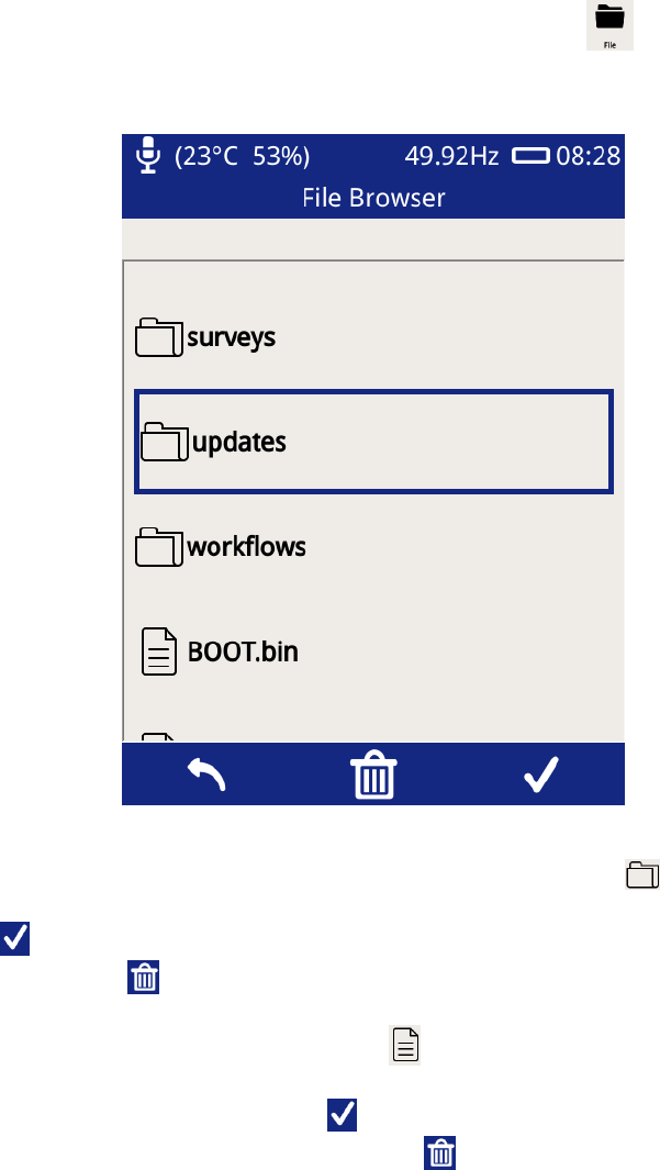
5.11 File Browser
The File Browser screen can be used to manage files and folders stored on the UltraTEV
Plus²’s microSD card. To access the file browser, click File icon on the Home screen.
Upon opening the File Browser, the contents at the root of the memory card will be
displayed. Selecting a folder, represented by the folder icon , will cause it to be
highlighted within the File Browser. The contents of the folder can then be displayed by
pressing the icon or the physical button below it on the instrument. A folder can be
deleted by pressing the icon or the physical button below it.
Selecting a folder, represented by the file icon , will cause it to be highlighted within the
File Browser. Information regarding the file such as size, date modified and time modified
can then be displayed by pressing the icon or the physical button below it on the
instrument. A file can be deleted by pressing the icon or the physical button below it.
EA Technology UltraTEV Plus2 Operating Manual 2388L018
Page 35 of 82
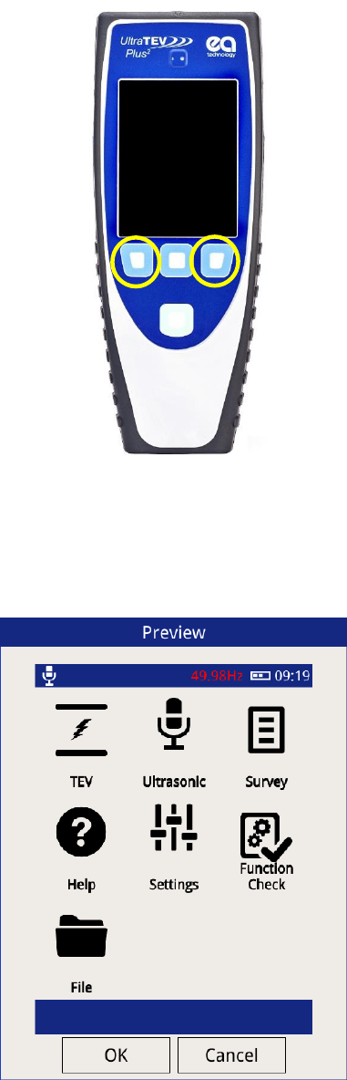
5.12 Screenshot
The UltraTEV Plus² allows the user to capture an image of the screen at any time. To initiate
a capture press both the left and right hand buttons simultaneously for two seconds.
Once capture completes a pop up window will appear giving a preview of the screen
capture. This preview can either be rejected by pressing cancel which discards the image
and returns to normal operations or accepted which will move onto the file naming screen.
EA Technology UltraTEV Plus2 Operating Manual 2388L018
Page 36 of 82
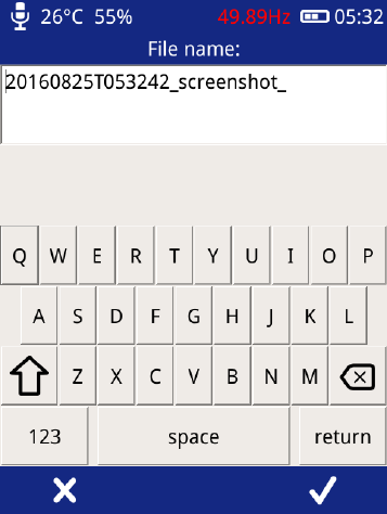
The file name screen provides the opportunity to rename the file from the default as shown
below. Selecting the tick in the bottom left hand corner of the image stores the file to the
removable microSD Card. The files are stored at \data and can be verified through the file
browser
The screen shot image can be viewed by removing the SD card and inserting in to a PC or
similar device and navigating to \data and opening the relevant .png file, or by connecting
to the UltraTEV Plus² interface.
EA Technology UltraTEV Plus2 Operating Manual 2388L018
Page 37 of 82
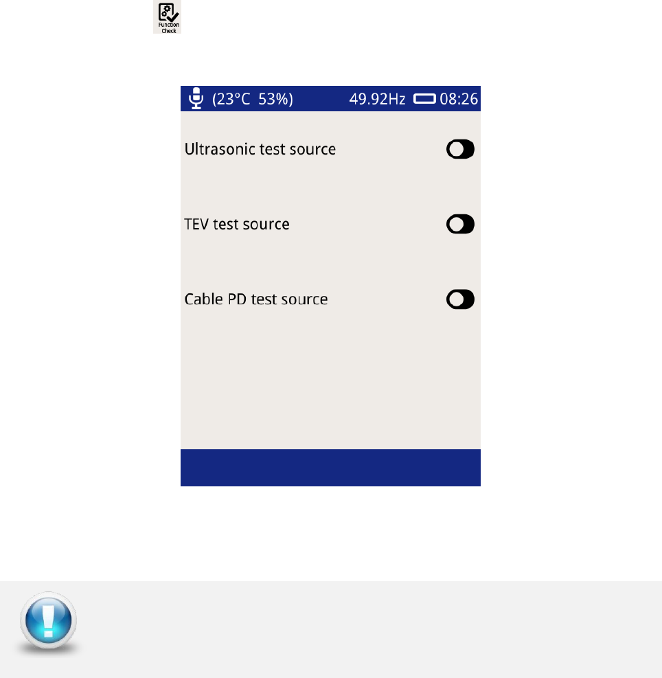
5.13 Function Check
The UltraTEV Plus²’s function checker is designed to allow users to verify the functionality
of their instrument using in built test sources. The Function Check display option can be
used to toggle these inbuilt test sources. To launch the Function Check display, press the
Function Check icon on the Home screen.
To test a given function, for example, the TEV function, toggle on the TEV test source.
Navigate to any of the TEV measurement displays which should display TEV activity.
Multiple test sources can also be toggled and checked.
Please note that this option is not in any form a calibration check.
EA Technology UltraTEV Plus2 Operating Manual 2388L018
Page 38 of 82
6. NFC Functionality
The UltraTEV Plus² has a built-in NFC tag reader/writer that can program the tags when
they are used for the first time and recall the information during a survey.
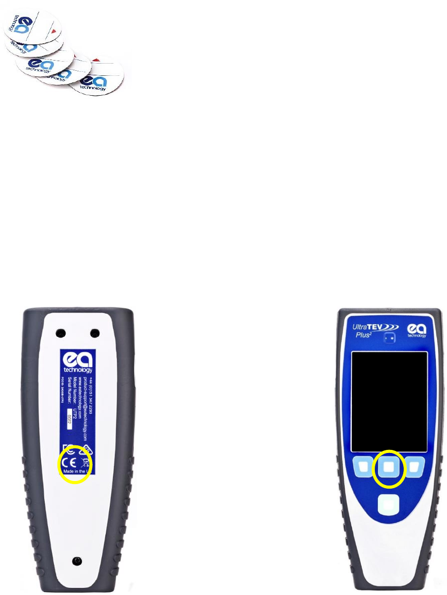
6.1 NFC Tag Installation
• NFC tags are not designed for outdoor installation
• NFC tags are designed to work on metal surfaces
• Clean the surface with alcohol prior to installation
• Install in a convenient place where the UltraTEV Plus² can be held in contact with
the NFC tag while the display is observed
NFC functionality is enabled by default. To turn off the NFC function, go to Main Menu,
Settings, Wireless Settings.
The NFC tag reader antenna
is located behind the CE
mark.
When taking a reading,
align the centre button with
the NFC tag.
Blank NFC tags are identical and can be programmed with
substation or asset information. There is a space on the tag
to write ‘asset’, ‘substation’ or other information.
EA Technology UltraTEV Plus2 Operating Manual 2388L018
Page 39 of 82
6.2 Substation Tag
Use one NFC tag per substation to hold all the information relative to the substation being
surveyed. This tag can be installed anywhere in the substation
The following information is stored:
Substation Name (up to 127 characters)
Substation type (Indoor, outdoor, cabinet, other)
Switchgear Manufacturer (up to 127 characters)
Switchgear Type (up to 127 characters)
Installation Date (Day, Month, Year)
Rated Voltage (In KV)
Operating Voltage (in KV)
Busbar Insulation Type (Unknown, Air, Oil, Compound, SF6, Paper, XLPE, EPR)
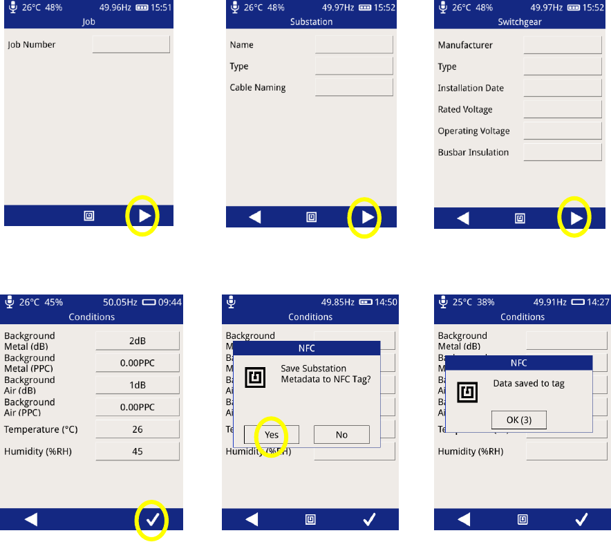
6.3 Writing to a Substation Tag
From the Main Menu select Survey, Start Survey, Skip Workflow
Enter unique survey reference
Enter substation name &
type
Enter switchgear information
Take background readings
Align the centre button with
the NFC tag
The UltraTEV Plus² will beep
once to indicate a tag has
been detected, followed by
EA Technology UltraTEV Plus2 Operating Manual 2388L018
Page 40 of 82
two beeps to indicate a
successful tag write.
Following a successful tag write, the UltraTEV Plus² will continue in Survey mode.
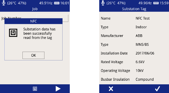
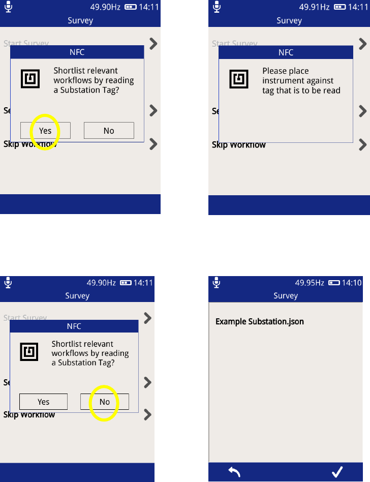
6.4 Reading a Substation Tag
Substation tag reads can take place in the Job, Substation and Switchgear screens within
Survey mode.
From the Main Menu select Survey, Start Survey, Skip Workflow. Align the centre
button with the NFC tag and press the centre button or NFC icon to trigger a scan.
The UltraTEV Plus² will beep once to indicate a tag has been detected, followed by another
beep to indicate a successful tag read.
Successful scan
Substation information
added to survey
6.5 Asset Tag
We suggest two NFC tags per panel, one on the front and one on the rear. The asset tag
will store the following information required in the Metadata screen of Survey mode.
Asset Name (up to 127 characters)
Panel Number (up to 127 characters)
EA Technology UltraTEV Plus2 Operating Manual 2388L018
Page 41 of 82
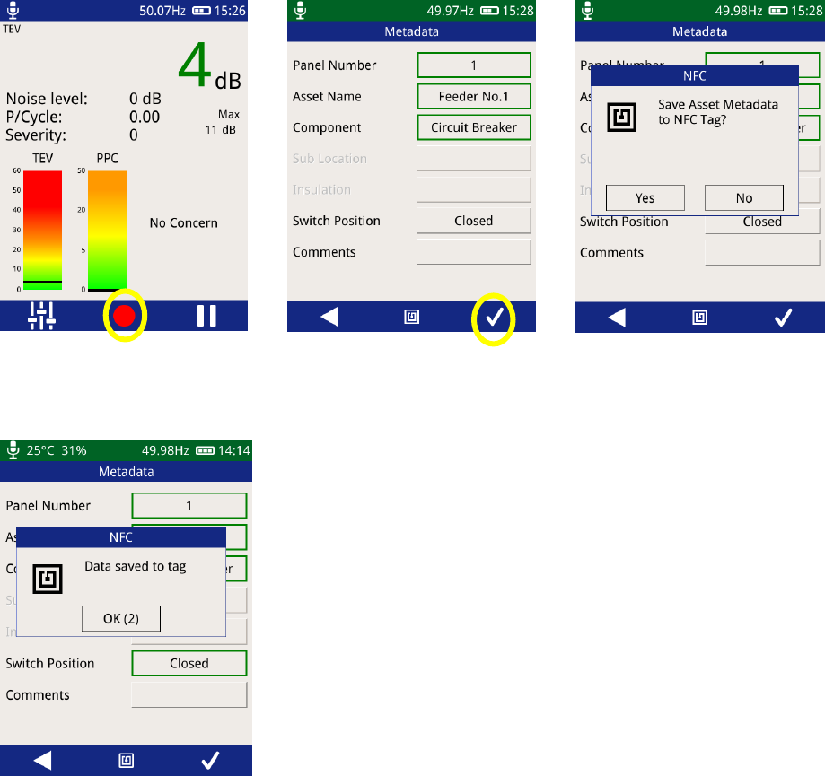
6.6 Writing to an Asset Tag
The recording data option is available in Survey, TEV and Ultrasonic mode.
On any screen press record
Input asset information
Select ‘yes’ and align the
centre button with the NFC
tag
The UltraTEV Plus² will beep
once to indicate a tag has
been detected, followed by
two beeps to indicate a
successful tag write.
Once completed, the asset information is available for re-call on future measurements.
EA Technology UltraTEV Plus2 Operating Manual 2388L018
Page 42 of 82
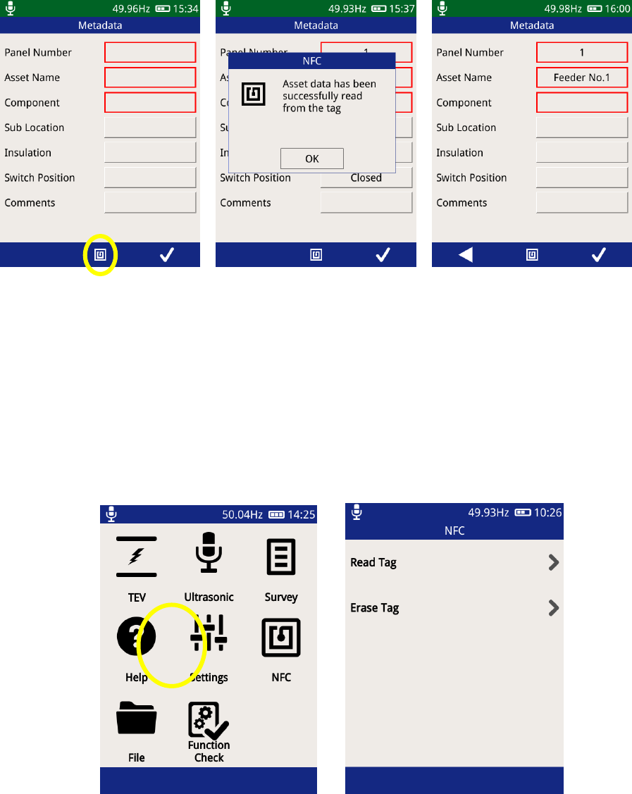
6.7 Reading an Asset Tag
Whenever the record option is used in Survey mode and the measurement ‘Metadata’ screen
is displayed, a tag read is possible.
Press the centre button or
NFC icon to trigger a scan
The UltraTEV Plus² will beep
once to indicate a tag has
been detected, followed by
another beep to indicate a
successful tag read.
Data will populate asset
information
6.8 Reading an NFC Tag from the Main Menu
NFC tags which have previously been written to, can be read or erased from the Main Menu.
EA Technology UltraTEV Plus2 Operating Manual 2388L018
Page 43 of 82
6.9 NFC Tag Trouble Shooting
‘blank tag detected, no data read’ The tag has no data
‘wrong tag type’ Attempting to read substation data from an asset
tag
‘no tag detected’ Re-position the UTP2 in contact with the NFC tag
and try again.
EA Technology UltraTEV Plus2 Operating Manual 2388L018
Page 44 of 82
7. Survey
The Survey mode of the UltraTEV Plus² is a powerful yet easy way to collect and store data
from a range of assets. Data from TEV, Cable PD or Ultrasonic measurement modes can be
recorded and stored with corresponding metadata linking the data and its associated
context.
All data recorded on the UltraTEV Plus² takes the form of a survey in order to give the data
context and a common structure for use when analysing the data offline.
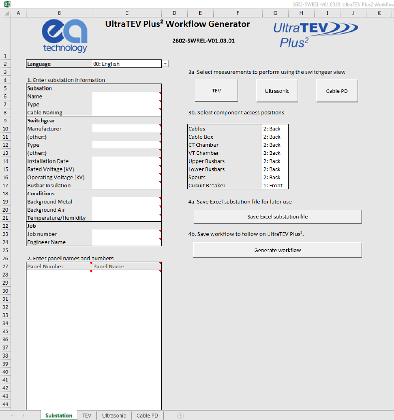
7.1 Create a Workflow using the Workflow Generator
Workflows are a pre-populated description of the measurements to be undertaken as part
of a substation survey. A workflow consists of information regarding the assets and the
specific measurements per asset that are to be performed.
Insert the UltraTEV Plus² SD card into your PC or laptop and open the Workflow Generator
with Micorsoft Excel.
EA Technology UltraTEV Plus2 Operating Manual 2388L018
Page 45 of 82
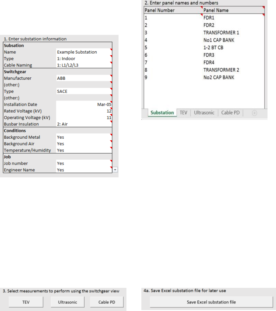
1. Enter substation information
Substation name cannot contain any
special symbols *%^$#@!’ etc.
Pre-defined fields for Manufacturer and
Type, or customise to suit by selecting
‘Other:’.
We recommend selecting ‘Yes’ in
Conditions/Job fields. ‘Yes’ will request
that they are measured/entered during
PD survey.
2. Enter Panel Names and Numbers
Maximum of 63 panels.
We recommend panel number 1 through
to required number in sequential order.
Panel names must be unique and are case
sensitive.
3. TEV, Ultrasonic or Cable PD
Locations
Pre-determined locations for TEV,
Ultrasonic or Cable PD can be designed
into the substation layout.
This information is reviewed using the
‘View Progress’ screen within the
UltraTEV Plus².
4a. Save Excel Substation File
Save the Excel Substation File for later use.
This allows for any changes to be made to
Substation details or layout in the future
The name of the Excel file will be
‘substation-name.xlsm’.
EA Technology UltraTEV Plus2 Operating Manual 2388L018
Page 46 of 82
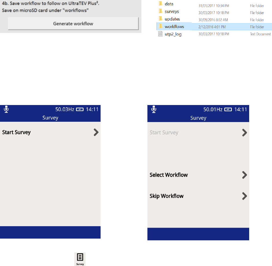
4b. Save Workflow to PC
Save the workflow file so that it can be used in
the UltraTEV Plus² Instrument during a PD
survey.
The file will be saved as substation-name.json.
4b. Save Workflow to SD card
Save the workflow file or substation-
name.json file under the folder
‘workflows’ in the UltraTEV Plus² units
microSD card.
If this folder does not exist, it must be
created (case sensitive).
7.2 Starting a Survey
There are two ways to start a survey; either by going through the Survey display off the
Main menu, or by starting a data capture from any measurement screen.
Pressing the Survey icon on the Main menu will display the Survey Mode display. This
display allows users to start, stop and view the progress of a survey.
To start a survey, press ‘Start Survey’ on the display. Doing this will show two options to
select from; Select Workflow or Skip Workflow.
EA Technology UltraTEV Plus2 Operating Manual 2388L018
Page 47 of 82
7.3 Select Workflow
Recall workflow from substation tag
Read tag
Go to workflow list
Select workflow
EA Technology UltraTEV Plus2 Operating Manual 2388L018
Page 48 of 82
Enter your unique job number, the substation and switchgear information will be filled in
using the information from the Workflow.
Capture background readings, if ‘yes’ was not selected when the workflow was created,
this data will not be captured.
A workflow can be created from a previous survey using the ‘Generate Workflow’ option in
the UltraTEV Plus² interface page.
EA Technology UltraTEV Plus2 Operating Manual 2388L018
Page 49 of 82
7.4 Skip Workflow
To perform a survey without a workflow, press the “Skip Workflow” button. Similarly to the
Workflow route, a series of forms will be displayed with fields about the substation,
switchgear and conditions. The form field can be populated using the inbuilt virtual
keyboard or a drop down list of available options.
7.5 Ad-hoc Measurement
If a survey is not in progress when the record button is pressed in any of the TEV, Cable PD
or Ultrasonic measurement screens the data is still captured. On completion of the record,
the default survey information fields are displayed to capture the measurement context
data. This data is the same as entered when starting a survey through the menu icon. Once
this information has been entered, survey mode stays active ready for further data to be
recorded and added to the survey.
7.6 Survey Metadata Forms
As mentioned in the previous section, each survey requires the input of information about
the substation the survey is being conducted in. Some fields have populated lists of values
to select from, with each having the option to override by inputting a custom value, others
allow only virtual keyboard input and a select few have special behaviours.
Navigation through the forms is done using the left and right buttons on the menu bar or
using the corresponding physical buttons. The last form to be populated is indicated by
the right hand button on the menu bar changing to become a tick icon. Pressing this will
close the last form, save the entered information and return to the home menu ready to
start recording data.
If a workflow is not being used, the default form fields used are set out below along with
their behaviour:
Form
1
Name
Job
Field
Description
Behaviour
Job Number
The job number of the survey, used by
many users to link a survey to a contract
or package of work
Pressing the input field will show
the virtual keyboard
The Notification bar changes from blue to green to indicate a survey is
currently running.

EA Technology UltraTEV Plus2 Operating Manual 2388L018
Page 50 of 82
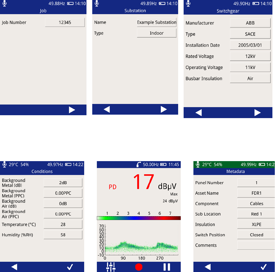
Form
2
Name
Substation
Field
Description
Behaviour
Name
Name of the substation being surveyed
Pressing the input field will show
the virtual keyboard
Type
Type of the substation being surveyed
Pressing the input field will show a
populated list of substation types,
with the option to enter a custom
value using the virtual keyboard
Form
3
Name
Switchgear
Field
Description
Behaviour
Manufacturer
Manufacturer name of the switchgear
being surveyed
Pressing the input field will show a
populated list of switchgear
manufacturers, with the option to
enter a custom value using the
virtual keyboard
Type
The type of switchgear being surveyed
Pressing the input field will show a
populated list of switchgear types
with the option to enter a custom
value using the virtual keyboard
Installation
Date
Installation date of the switchgear
Pressing the input field will show a
date selector to input the
switchgear installation date
Rated
Voltage
The rated voltage of the switchgear
Pressing the input field will show a
populated list of voltages with the
option to enter a custom value
using the virtual keyboard
Operating
Voltage
The operating voltage of the switchgear
Pressing the input field will show a
populated list of voltages with the
option to enter a custom value
using the virtual keyboard
Busbar
Insulation
The insulation material of the
switchgear's busbar
Pressing the input field will show a
populated list of busbar insulation
materials with the option to enter a
custom value using the virtual
keyboard

EA Technology UltraTEV Plus2 Operating Manual 2388L018
Page 51 of 82
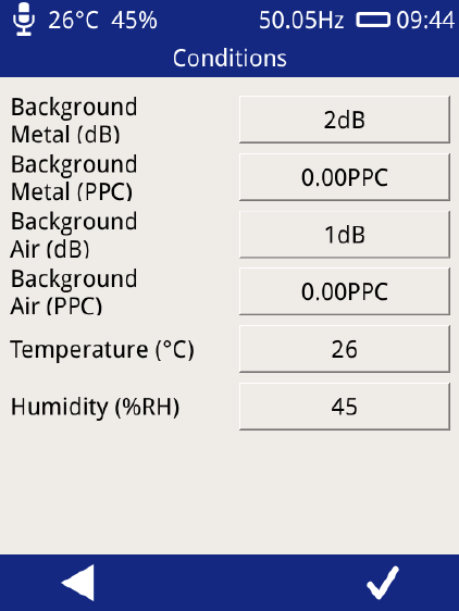
Form
4
Name
Conditions
Field
Description
Behaviour
Background
Metal
Background metalwork TEV value
Pressing the input field will cause a
background TEV measurement to
be performed
Background
Air
Background Air TEV value
Pressing the input field will cause a
background TEV measurement to
be performed
Temperature
Temperature as read by the
Environmental Sensor
Pressing the input field will cause it
to be populated with the current
Temperature. The Temperature &
Humidity sensor must be connected
to do this.
Humidity
Humidity as read by the Environmental
Sensor
Pressing the input field will cause it
to be populated with the current
Humidity. The Temperature &
Humidity sensor must be connected
to do this.
EA Technology UltraTEV Plus2 Operating Manual 2388L018
Page 52 of 82
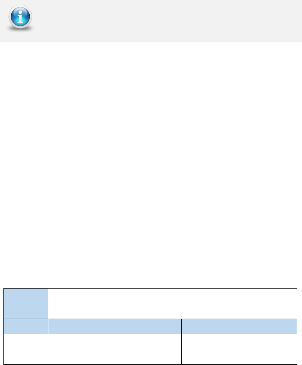
7.7 Using Populated Lists
Populated lists used in many of the above fields will look like that of below.
The list can be scrolled by dragging the list up and down using a finger or stylus. Selecting
an item is done by pressing an item then pressing the tick in the menu bar. If the “Other…”
option is selected a virtual keyboard prompt will be displayed for custom input. If the cross
in the menu bar is pressed, the list will be closed and no input recorded.
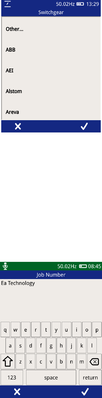
7.8 Using the virtual keyboard
The virtual keyboard allows custom text to be input. Characters can be input using the
buttons on the layout, with additional characters and numbers available through the “123”
button. Uppercase letters can be entered by pressing the arrow (between A and Z). Double
tapping the 0arrow will activate Caps lock, giving uppercase letters until it is next pressed.
To accept the input text as input to the field, press the tick button on the menu bar, to
cancel, press the cross on the menu bar of the Left button.
EA Technology UltraTEV Plus2 Operating Manual 2388L018
Page 53 of 82
7.9 Background Measurements
The background measurements fields on the survey metadata forms have special
behaviour, pressing the input field triggers the UltraTEV Plus² to start measuring the TEV
level for a ten second period. Following this, the average measurement for the period is
stored. When performing the Background Metal measurement, the TEV plate of the UltraTEV
Plus² should be held against an unearthed piece of metalwork in the substation not
connected to the switchgear. The Background Air measurement requires holding the
instrument in free space in order to get an ambient reading.
The background temperature and humidity is taken directly from the current measurement
by the Environmental Sensor. Please note that the sensor needs to be connected to the
UltraTEV Plus² device.
EA Technology UltraTEV Plus2 Operating Manual 2388L018
Page 54 of 82
7.10 Recording Data
Once a survey has been started, data can be recorded from any TEV, Cable PD or Ultrasonic
displays. The same data is recorded for TEV or Cable PD independent of which TEV/Cable
PD screen is currently displayed. To record data, simply press the record icon visible on the
menu bar, which will then start a 10 second period of data capture.
Different data is recorded for the different measurement modes as summarised below:
7.10.1 TEV recorded data
When recording data in any of the TEV modes, the following data is recorded and stored:
• Event data including phase angle, cycle count, amplitude, pulse width and rise time
• TEV Waveforms
• TEV audio
7.10.2 Cable PD recorded data
When recording data in any of the Cable PD modes, the following data is recorded and
stored:
• Event data including integral, pulse width and rise time
• Cable PD Waveforms
7.10.3 Ultrasonic recorded data
When recording data in Ultrasonic measurement modes, the following data is recorded and
stored:
• Raw Ultrasonic audio
• Heterodyned Ultrasonic audio
• Processed Ultrasonic audio
EA Technology UltraTEV Plus2 Operating Manual 2388L018
Page 55 of 82
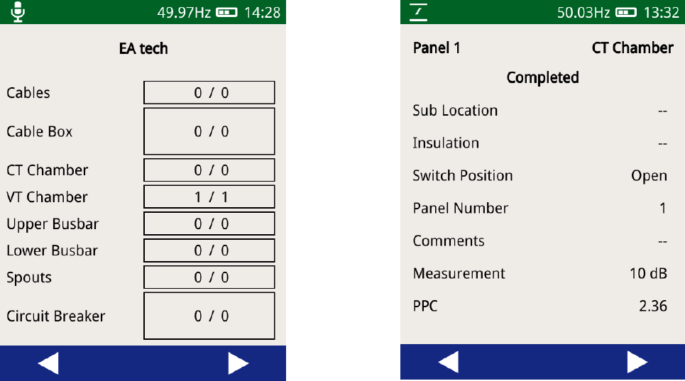
7.11 Viewing Survey Progress
The progress of a survey can be viewed at by navigating to the Survey menu then pressing
‘View Progress’. The view progress display shows a top view of a switchgear panel with
the different components making up a panel separated out. Each component shows the
total number of measurements taken on that component against the number of expected
measurements. The expected measurements are only applicable to surveys which are
following a workflow, which sets out the measurements that should be taken as part of that
survey. Using the left and right buttons on the menu bar, other panels within the survey’s
progress can be viewed.
Pressing any component on the panel view will display details of the measurements on that
component, including the measurement location, sub-location and average measurement
values.
EA Technology UltraTEV Plus2 Operating Manual 2388L018
Page 56 of 82
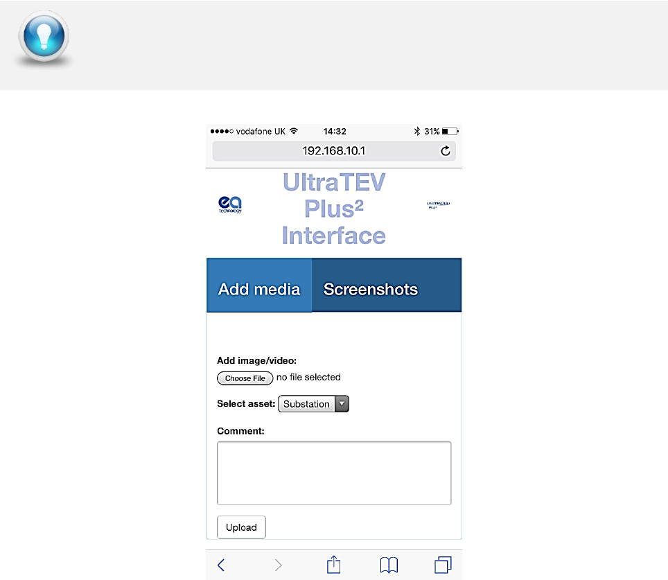
7.12 Adding Media to a Survey
A photograph or video can be added to the survey file by connecting your smart device to
the UltraTEV Plus², via the Hotspot function, To add an image or video, open the UltraTEV
Plus² interface by entering 192.168.10.1 to your web browser and select ‘add image/video’.
7.13 Completing a Survey
A survey can be completed at any time by going to the Survey Menu and pressing the “Stop
Survey” button. Upon completing a survey, a summary of the survey is written to the survey
directory and the entire directory is archived into a zip file for safe keeping. If a large
amount of data has been recorded, archiving the data can take up to a minute. Once
archiving is completed the notification bar will return to its blue colour indicating that a
survey is now no longer in progress.
Create a shortcut on your mobile device’s homepage for quick access to the
UltraTEVPlus² interface
EA Technology UltraTEV Plus2 Operating Manual 2388L018
Page 57 of 82
8. Reviewing Results
• Data collected during Survey mode or though ad-hoc recording is stored on the
UltraTEV Plus²’s MicroSD card. To facilitate viewing of the data the UltraTEV Plus²
provides four methods of connection.
• Hotspot – Allows direct connection via the UltraTEV² personal hotspot to a Wi-Fi
enabled device
• Wi-Fi – Allows a direct connection from the UltraTEV Plus² to a Wi-Fi enabled device.
• USB – Direct connection from the UltraTEV Plus² to a Windows based machine.
Removal of the MicroSD card for viewing on a Windows/Linux/ Mac OS X based
machine.
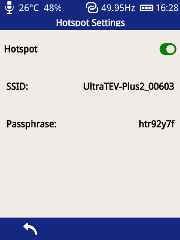
8.1 Hotspot Connection
Go to Main Menu, Settings, Wireless Settings and enable Hotspot. Go to Wi-Fi settings on
your Wi-Fi device, select the SSID and enter the Passphrase.
Once connected, enter the IP address 192.168.10.1 in a web browser such as Google
Chrome, Mozilla Firefox or Microsoft Edge/Internet Explorer.
EA Technology UltraTEV Plus2 Operating Manual 2388L018
Page 58 of 82
8.2 Wi-Fi Connection
Go to Main Menu, Settings, Wireless Settings and enable Wi-Fi. Select Network Connect,
choose your network from the list and connect. Once connected, go to Network Status and
make a note of the IP address. Enter this IP address in a web browser such as Google
Chrome, Mozilla Firefox or Microsoft Edge/Internet Explorer.
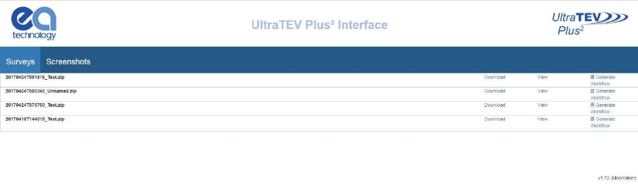
The home page, shown below displays a list of all surveys and screenshots stored on the
UltraTEV Plus²’s MicroSD Card.
8.3 USB Connection (Windows PC only)
Connect the UltraTEV Plus² via the USB port using the supplied cable. The UltraTEV Plus²
should install as an Ethernet Gadget.
If the drivers do not install automatically, you can install them as follows:
Go to device manager and select the instrument from the network adaptors list, it will have
a yellow triangle by it, then right click this and update driver software:
• Browse my computer for driver
• Let me pick from list of drivers on my computer
• Network adaptors
• Microsoft Corporation
• Remote NDIS based internet sharing device, next install
Note: The user needs to have administrator rights for the computer.
The index of surveys on the UltraTEV Plus² can be used to quickly identify the site of interest
allowing the user to navigate either directly to the data analysis (view button) or to
download a zip file (compressed folder) containing the raw data (download button).
Clicking the view button takes the user to the data analysis screens detailed overleaf.
EA Technology UltraTEV Plus2 Operating Manual 2388L018
Page 59 of 82
8.4 MicroSD Card & Data Zip Files
An alternative method of viewing the data held on the UltraTEV Plus² is by direct file access.
This can either be from a previously downloaded data zip as above or by accessing the
MicroSD card directly.
To directly access the MicroSD card ensure the UltraTEV Plus² is powered down, then locate
the MicroSD card at the base of the instrument and gently push on the card to eject it.
The MicroSD card will contain a separate .zip file (compressed folder) for each survey and
ad-hoc measurement undertaken. Inside each folder there is an html page named
‘index.html’. Extracting the zip file and then opening the ‘index.html’ file inside this folder
will direct you to the analysis pages.
8.5 Data Analysis Screens
The UltraTEV Plus2 has a web interface for analysing data captured by the instrument. These
analysis pages can be accessed through a web browser or downloaded for offline analysis
as detailed above.
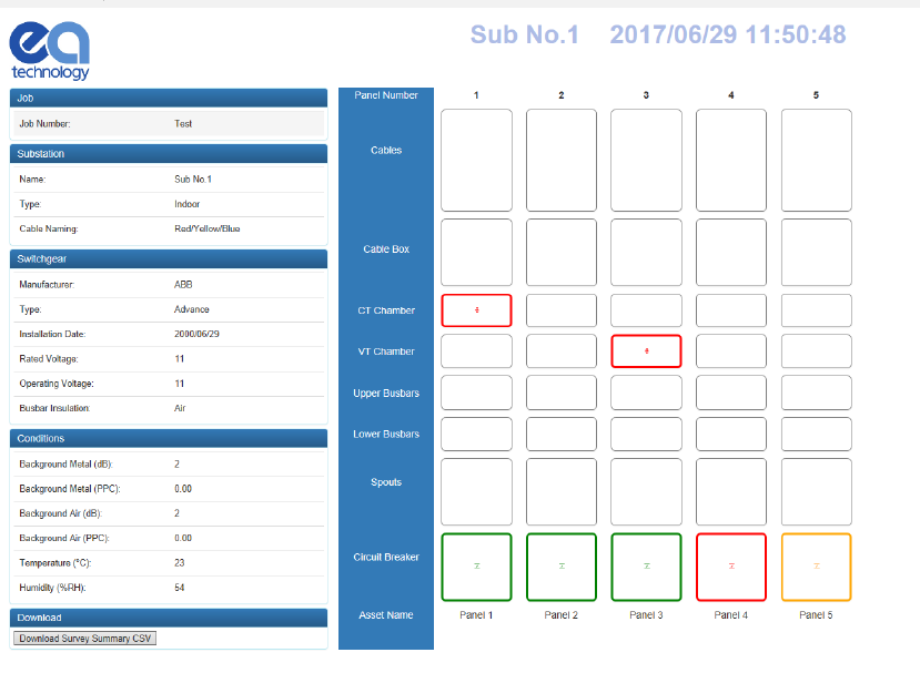
Following selection of ‘View’ on the landing page, or opening of an ‘index.html’ file from
the decompressed zip folder, a new page will appear with a visualisation of the switchgear
surveyed.
The overview or ‘index’ page provides diagrammatic representation of the switchgear
surveyed along with an icon detailing each measurement. An overview of the metadata
entered during the substation visit is included on the left hand side of the page. This data
EA Technology UltraTEV Plus2 Operating Manual 2388L018
Page 60 of 82
includes substation information such as site name and switchgear information such as
manufacturer, voltage etc. Below the metadata on the left hand side of the page a
‘download survey summary’ button is available. When pressed this button downloads a
Comma Separated Variable (CSV) file containing an overview of the survey results.
The measurement icons shown below are positioned on the panels as per the location
entered during the site survey. Clicking any of the available measurements on a panel
component will open the analysis page for the corresponding measurement. The
measurement section is colour coded, to correspond with the green/amber/red thresholds.
- TEV
- Cable PD
- Ultrasonic
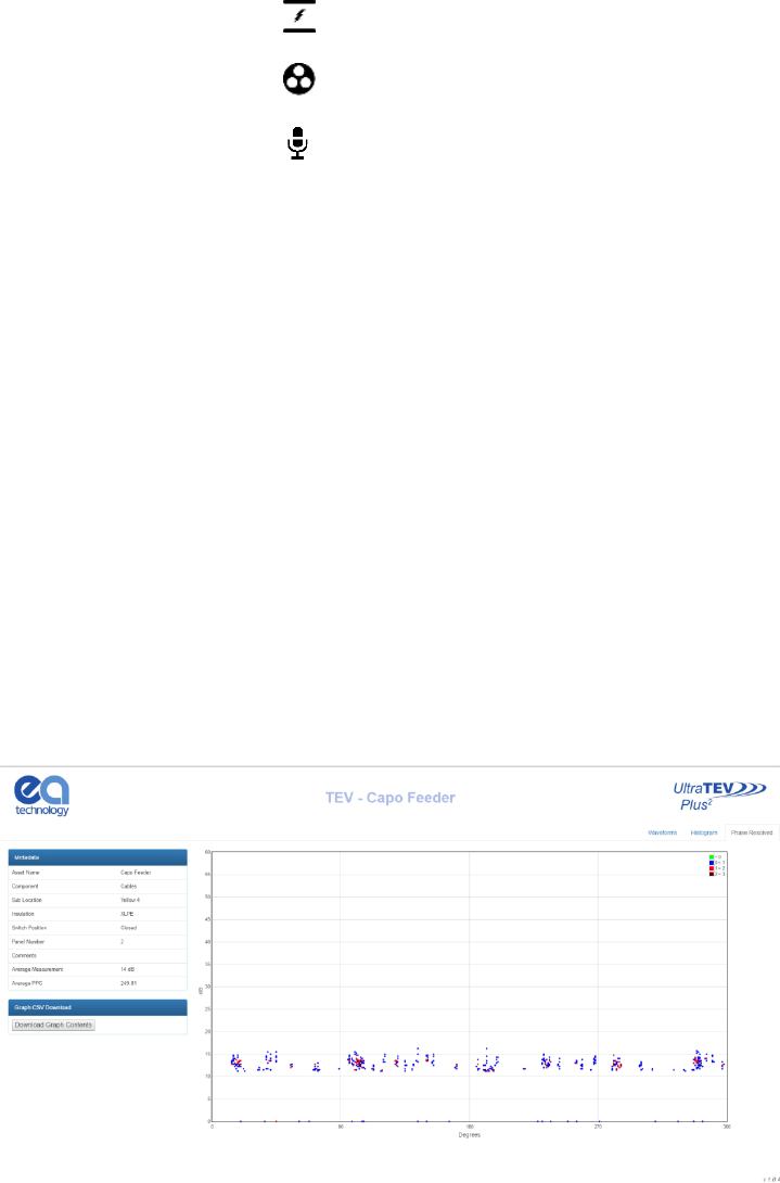
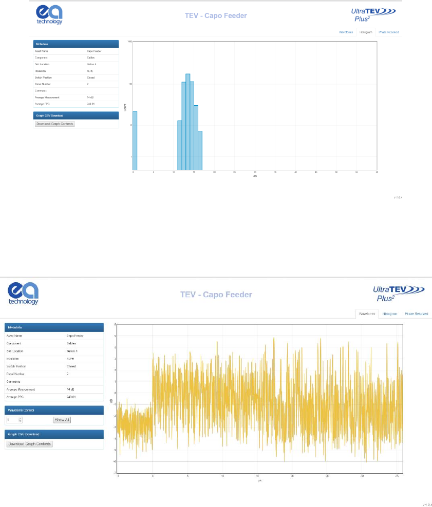
8.5.1 TEV & Cable PD Analysis Screen
Both TEV and Cable PD recorded data share the same suite of analysis screens. Once a TEV
or Cable PD measurement has been selected from the index page a new tab will open in
the browser displaying the analysis page corresponding to the measurement selected.
Multiple individual analysis pages can be opened simultaneously in this way to aid
comparison.
The TEV and Cable PD analysis pages both have metadata regarding the current
measurement on the left side of the page, with another button beneath to download the
raw dataset for each graph to CSV. The chart displayed on each page can be changed
between Waveform, Histogram and Phase Resolved by clicking the tabs in the upper right
hand corner.
Both Phase Resolved and Waveform graphs are able to be zoomed by clicking and dragging
on the graph area; the original zoom level can be returned to by clicking the respective
graphing tab in the upper right hand corner. Hovering the mouse over a point/bar on each
respective graph will produce a tooltip with information regarding that event. On the Phase
Resolved graph a legend can be seen on the upper right of the graph area, indicating the
scaling of colours for each point.
EA Technology UltraTEV Plus2 Operating Manual 2388L018
Page 61 of 82
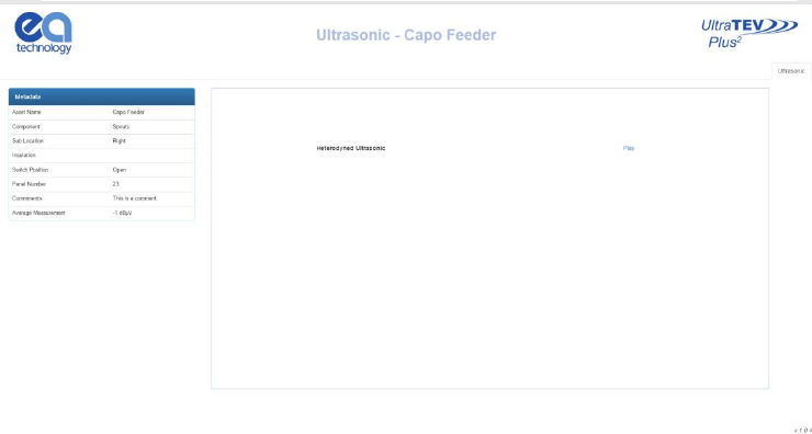
When the Waveforms tab is opened, a new control will appear beneath the metadata on the
left. The ‘Waveform Control’ section allows navigation through the waveforms collected
using the up/down arrows next to the waveform number. The ‘Show All’ button can be
used to show all waveforms on the same graph.
EA Technology UltraTEV Plus2 Operating Manual 2388L018
Page 62 of 82
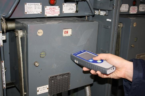
8.5.2 Ultrasonic Analysis
Once an ‘Ultrasonic’ measurement has been selected on the index page, a new tab will
open in the browser with the analysis page corresponding to the measurement selected.
The metadata section will be displayed to the left side of the page, and the ‘Play’ button
aligned with the ‘Heterodyned Ultrasonic’ label can be used to listen to or download the
.wav file (browser dependent). If the browser does open the file and begin to play it, right
click the player and select ‘Save file as’ to save the file.

EA Technology UltraTEV Plus2 Operating Manual 2388L018
Page 63 of 82
9. Detecting Partial Discharge using the UltraTEV
Plus²
Due to the tri-sensor capability, the UltraTEV Plus² is able to detect Partial Discharge activity
on the surface of insulation using Ultrasonic detection, internal to insulation by measuring
TEV signals and in cables and cable accessories using the RFCT accessory.
This section covers how to use the UltraTEV Plus² to detect PD activity using the three
sensor technologies.
9.1 TEV Measurement
TEV measurements are performed using the TEV sensor embedded into the front face of
the instrument.
9.1.1 Background Noise
Electromagnetic signals from sources outside the switchgear can also produce voltages on
the outside of the switchgear. These electromagnetic sources can come from a multitude
of sources such as overhead line insulators, transformer bushings and strong radio signals.
These sources will produce equivalent signals on metalwork which is not electrically
connected to the switchgear such as metal substation doors or fencing. Measuring the
interference levels on these surfaces before taking readings from the switchgear will help
allow identification of PD over background noise.
TEV measurements cannot be taken with the RFCT accessory connected to
the instrument
If the background noise is less than 10dB then the UltraTEV Plus² pulse
counter is not incremented and will read zero
EA Technology UltraTEV Plus2 Operating Manual 2388L018
Page 64 of 82
9.1.2 Measuring TEV
Switch on the UltraTEV Plus² and wait until home menu is displayed. Press the TEV icon on
the home menu then choose which TEV display is required. The ‘Interpretation’ display is
recommended for first pass with the advanced functionality of the other modes being
utilised to further inform the user once a signal is detected.
To take a measurement, hold the TEV sensor squarely against the metalwork of the asset
under test as shown overleaf. Any readings will be displayed on the screen with the
interpretation message adjusted to take account of the reading’s amplitude and pulses per
cycle. Please note that the readings will not remain on the screen once the TEV sensor has
been removed from the metalwork.
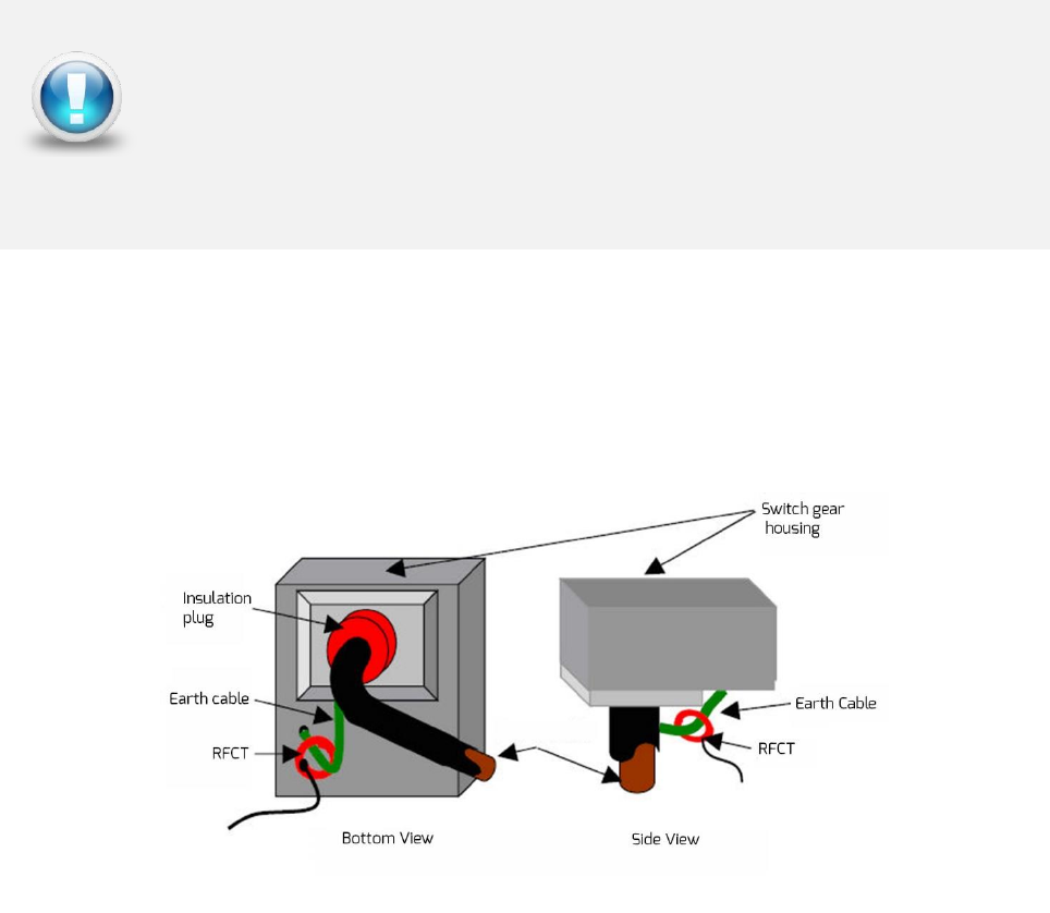
EA Technology UltraTEV Plus2 Operating Manual 2388L018
Page 65 of 82
9.2 Cable PD Measurement
To perform Cable PD measurements, the RFCT accessory needs to be connected to the
UltraTEV Plus². The RFCT connects to the Smart accessory port found on the left hand side
of the instrument.
9.2.1 Practical RFCT Connection Requirements
Using the RFCT for online PD tests on medium voltage power cables requires direct access
to the earth bonding strap. If present the split core radio frequency current transformer
RFCT can simply be clamped around the earth cable. This method can be used on-line
without disconnecting cables or switching off supplies to customers.
With XLPE cable installations the user can normally get access to the cable earth strap or
the core of the cables. The earth strap can be looped out of the termination box to give
better access. With PILC (Paper Insulated Lead Covered) cables difficulty may arise attaching
the RFCT as the cable earth and switchgear earth can be bonded together. This is more
usual on older PILC cables using compound filled cable boxes.
9.2.2 Measuring PD in cables
Switch on the UltraTEV Plus² and wait until home menu is displayed. If the conditions set
out above are met, install the RFCT around the earth strap of the cable under test. Proceed
to connect the fitted RFCT to the UltraTEV Plus² using the supplied cable; connect the BNC
to the RFCT and the LEMO™ connector into the Smart accessory port. The home menu on
the UltraTEV Plus² will now display a Cable PD icon in place of the usual TEV icon.
EA Technology RFCTs are designed to be installed by suitably competent
operators on cable earth/ground straps which are suitably and efficiently
connected to earth/ground to maintain safety.
RFCTs, connecting leads and test equipment do not provide protection
against high voltage.
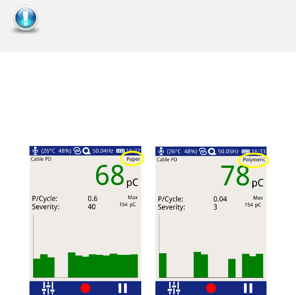
EA Technology UltraTEV Plus2 Operating Manual 2388L018
Page 66 of 82
RFCTs, connecting leads and test equipment do not provide protection
against high voltage. Ensure that the accessory is only connected to cables
at earth potential.
Press the Cable PD icon on the home menu and proceed to press on the Measure option.
The screen will display a bar graph of the measured PD values in picocoulombs (pC). To
obtain a further insight into the discharge activity on a cable, select the ‘Phase Plot’ option
on the Cable PD screen. This screen provides a phase resolved reading of Cable PD activity
within the cable under test.
The cable type can be changed by pressing the text ‘paper’ or ‘polymeric’. The UltraTEV
Plus² green/amber/red thresholds will change according to which cable insulation type has
been selected.
9.3 Ultrasonic Measurement
The UltraTEV Plus² is equipped with a built-in ultrasonic sensor which can be used to detect
the acoustic emissions of surface partial discharge activity. External ultrasonic sensors are
also available to use with the UltraTEV Plus² allowing use in outdoor compounds, on sealed
assets or in hard to reach places. When taking airborne ultrasonic readings the sensor
should not touch the asset or plant being investigated.
9.3.1 Measuring Ultrasonic
Switch on the UltraTEV Plus² and wait until home menu is displayed. Proceed to plug in the
supplied Headphones; select the Ultrasonic icon on the main menu. The screen will now
display a phase resolved plot of ultrasonic activity.
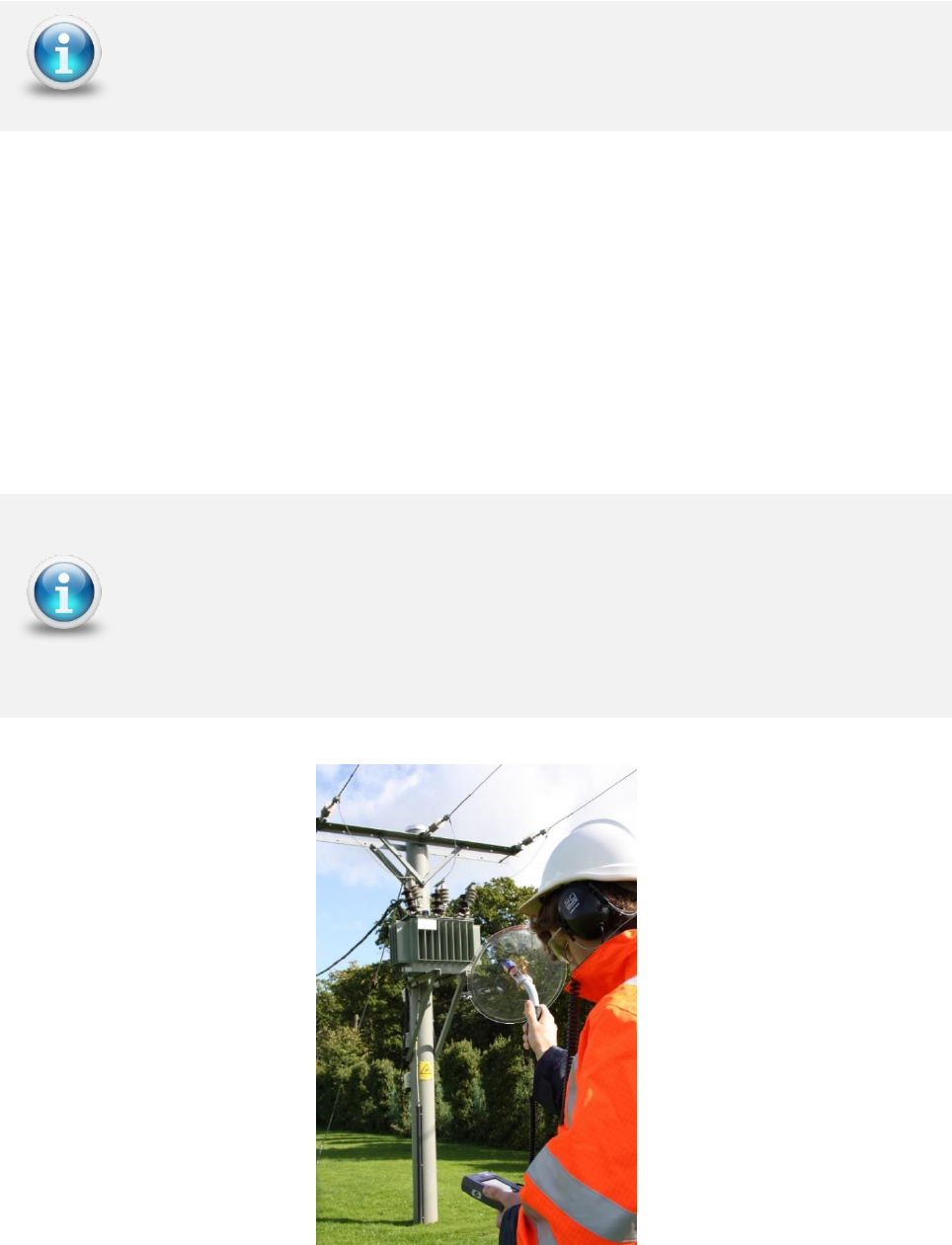
EA Technology UltraTEV Plus2 Operating Manual 2388L018
Page 67 of 82
Ultrasonic activity above the background level may be significant. Genuine discharge can
be identified by a crackling sound (like a sizzling frying pan) in the headphones or by phase
related groups on phase plot. Further confidence of a detection can be obtained by the
classification algorithm output displayed on the top left of the screen.
9.3.2 Measuring Ultrasonic with the UltraDish
The UltraDish provides a means of detecting discharge sources at a distance. It comprises
a transparent parabolic reflector that focuses the ultrasonic sound on to a sensor mounted
at the focus point of the reflector. The UltraDish gives an effective increase in gain
compared to the built in sensor allowing discharges to be detected at much greater
distances such as insulator strings on overhead assets.
To use an UltraDish the connector must be plugged in to the Ultrasonic sensor input on
the side of the UltraTEV Plus². The UltraDish is aimed at the point of interest with either
the optical sight or by switching on the laser pointer with the button on the handle.
The UltraTEV Plus² defaults to the built-in ultrasonic sensor if no accessory
is plugged into the Ultrasonic Accessory port
Due to the gain of the UltraDish, readings taken with the UltraDish cannot
be compared to readings taken with the Internal Sensor, the Flexible Sensor
or the Contact Probe.
This accessory is available with the Kit 3 package. To discuss procuring this
accessory please contact the product support team via email:
product-support@eatechnology.com
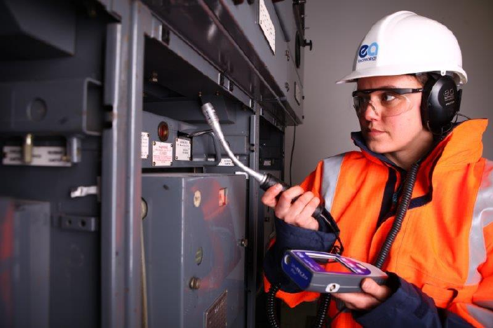
EA Technology UltraTEV Plus2 Operating Manual 2388L018
Page 68 of 82
9.3.3 Measuring Ultrasonic using the Flexible Sensor
The Flexible Sensor provides a means of reaching inaccessible parts on the switchgear. The
sensor is mounted at the end of a flexible goose-neck which allows the angle of the sensor
to the handle to be adjusted. This allows the user to make measurements where it would
be difficult to use the built in sensor and still be able to read the display.
To use a Flexible Sensor the connector must be plugged into the external sensor input on
the Ultrasonic Accessory port of the UltraTEV Plus². To avoid damage to the socket or
connector ensure that the red dots are lined up before attempting to plug in the Flexible
Sensor. The Flexible Sensor is used in the same manner as the Internal Sensor.
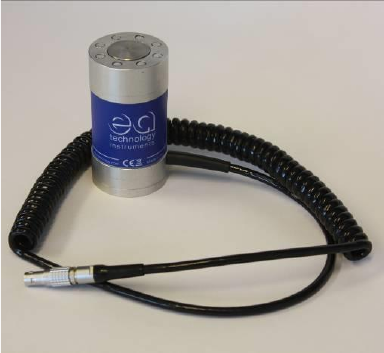
EA Technology UltraTEV Plus2 Operating Manual 2388L018
Page 69 of 82
9.3.4 Ultrasonic Measurement using the Contact Probe Accessory
The Ultrasonic Contact Probe is provided to enable discharges to be detected in enclosed
areas where there is no direct air path from the discharge source to the sensor. The Probe
connects to the external sensor connector and is clamped on to the area of interest using
the magnets surrounding the sensor plate. To avoid damage to the socket or connector
ensure that the red dots are lined up before attempting to plug in the Ultrasonic Contact
Probe. The probe will detect discharge sources inside the enclosed area by detecting the
energy transmitted to the enclosure. Care must be taken to eliminate other sources that
could cause the signals from discharges to be masked, e.g. accidental movement of the
probe itself or strong vibration on the panel.
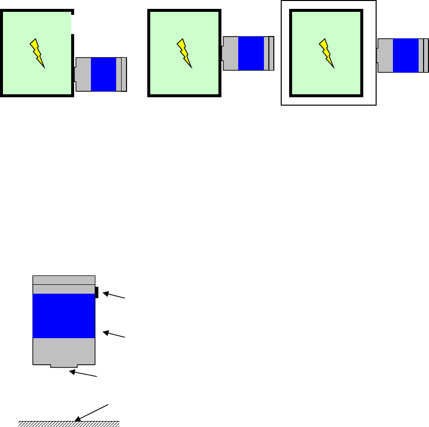
EA Technology UltraTEV Plus2 Operating Manual 2388L018
Page 70 of 82
9.3.5 Using the Ultrasonic Contact Probe
The Ultrasonic Contact Probe should be used if there is not a direct path between the PD
source and instrument sensor as shown in the second image below. However, it must not
be used if the tank containing the expected PD source is separated with another layer
(shown in the third image). In cases where there is a direct air path between the source of
PD and the instrument, an airborne sensor should be used as shown in the first image
below. Due to the physics of ultrasound, in most cases using an airborne sensor may offer
better sensitivity than that obtained using the Ultrasonic Contact Probe.
1) Ultrasonic signal can propagate through the air path. The Ultrasonic Contact
Probe can be used; however, better results may be obtained using the airborne
sensor.
2) No available air gaps - using an Ultrasonic Contact Probe is the best practice.
3) There is no access to the tank containing PD source, neither the airborne sensor
nor the Ultrasonic Contact Probe will provide a valid reading.
CP
Surface PD
CP
Surface PD
CP
Surface PD
1
2
3
Contact
Sensor Head (stainless steel)
Aluminium Body
Cable Socket
Asset surface or measurement point
(Where the Ultrasonic Contact Probe is attached)
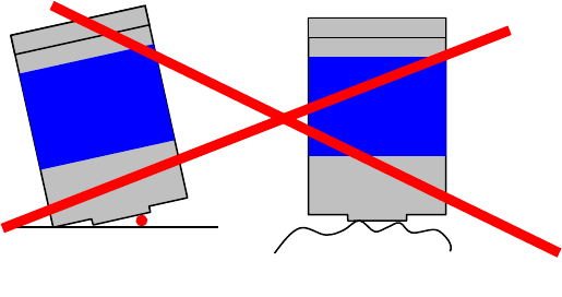
EA Technology UltraTEV Plus2 Operating Manual 2388L018
Page 71 of 82
9.3.6 Detection, Measurement and Localisation of the Partial Discharge
Detection of the Partial Discharge using the Ultrasonic Contact Probe is based on the PD
pattern recognition carried out by operators. The audio signature of a Partial Discharge
detected by the Contact Probe is similar to those obtained using airborne sensors. Special
care has to be taken to distinguish phantom signals from genuine signals caused by surface
PD.
Due to the differing propagation paths of the ultrasonic signals, measurements carried out
using the Ultrasonic Contact Probe cannot be compared against measurements carried out
using airborne sensors. In general signals detected by the Contact Probe are smaller as a
result of the physical properties of the asset and propagation path. Comparisons between
two measurements should only be made on assets of the same type using the same
configuration of the Contact Probe.
9.3.7 Mounting Practices
The Ultrasonic Contact Probe was designed to provide sufficient sensitivity to allow it to be
used to detect low level ultrasonic sources.
The image below shows scenarios where the Ultrasonic Contact Probe is mounted
ineffectively to the asset enclosure. Any air gap between Sensor Head and measurement
point will effectively attenuate signals to a level where even strong discharges will not be
detected. Therefore before any permanent or temporary installation, the Sensor Head and
asset surface need to be cleaned of any loose or unstable material. If the assets surface is
very rough and uneven this will create air gaps which will result in poor contact between
the Sensor Head and the asset.
1) Dust ingress between Ultrasonic Contact Probe Sensor Head and the asset surface
2) A rough or uneven surface will drastically decrease the amount of signal being
transferred to the Sensor Head
The images below show the correct way of mounting the Ultrasonic Contact Probe to the
asset in order to take a valid measurement. Ideally the Ultrasonic Contact Probe will be
attached to a relatively flat surface using its magnetic clamp. This will eliminate any
phantom noises which are described in the section below.
The second image shows a case where the surface is very rough and uneven. One of the
following couplants may be used:-
• Water based – suitable for quick measurement offers very good coupling.
• Oil based – suitable for long term monitoring as the oil will not evaporate quickly.
Contact
Contact
1
a
2
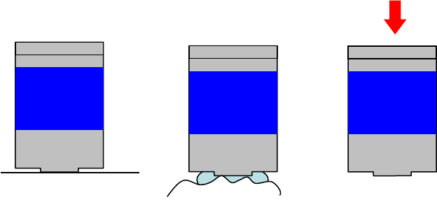
EA Technology UltraTEV Plus2 Operating Manual 2388L018
Page 72 of 82
• Solid state – suitable for long term monitoring but does not offer as good coupling
as oil based.
• Use of existing stickers on the switchgear such as ‘danger’ notices
The last image shows the application of pressure to the Ultrasonic Contact Probe against
the asset under investigation. This can improve the signal transfer and increases its
detection abilities. Please note, when the instrument dB values are read for comparison
purposes, always use the same type of the sensor, in the same position as previously used.
The asset measuring point can be marked on the plant item to facilitate easy location in
future.
1) Relatively flat and smooth surface
2) Using suitable couplant in the case of a rough surface
3) Carefully pressing the Ultrasonic Contact Probe towards the asset to increase
coupling may eliminate the need to use a couplant
Contact
Contact
1
2
Contact
3
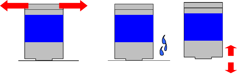
EA Technology UltraTEV Plus2 Operating Manual 2388L018
Page 73 of 82
9.3.8 Sources of Noise and Phantom Signals
The following images present some examples of how unwanted signals may be introduced
during the PD detection process when using the Ultrasonic Contact Probe. These can be
categorised as sources of noise and sources of phantom PD signals. The difference between
the two is that noise decreases our detection capabilities by masking the PD signal, whereas
phantom signals may be confused as a PD source.
The first image shows that when the UCP is kept in the hand during measurements, even
tiny movements of the hand can introduce significant noise to measurements through
surface noise. In cases where it is necessary to hold the Ultrasonic Contact Probe during
measurements (e.g. pushing the sensor to obtain more signal or non-magnetic asset
enclosure), a coupling fluid may help to reduce this type of noise.
Any vibrations of the asset surface caused for example by rain in outdoor assets or vibration
of transformers may cause phantom signals. In such cases the audible signal may be appear
exactly the same as a genuine PD source. These two examples are illustrated in the second
and third images.
1) Shaking Ultrasonic Contact Probe, e.g. when held in the hand
2) Rain in outdoor assets
3) Vibration (including transformers) of asset enclosure where the Ultrasonic Contact
Probe is attached
Contact
Contact
1
2
Contact
3
EA Technology UltraTEV Plus2 Operating Manual 2388L018
Page 74 of 82
10. UltraTEV Plus² Specification
TEV Measurements
Sensor: Capacitive
Measurement Range: 0 – 60 dBmV
Measurement Bandwidth: 3 – 80 MHz
Resolution: 1dB
Accuracy: ±1dB
Max Number of Pulses/Cycle: 1953 at 50Hz or 1627 at 60Hz
Min Level for Pulse Count: 10 dBmV
Ultrasonic Measurements
Sensor: Ultrasonic Microphone
Measurement Range: -7dBµV to 68 dBµV
Resolution: 1dB
Accuracy: ±1dB
Transducer Sensitivity: -65dB (0dB = 1volt/µbar RMS SPL)
Transducer Centre Frequency: 40 kHz
Transducer Diameter: 16mm
Cable PD Measurements
Sensor: Radio Frequency Current Transformer
Measurement Range: 100 – 100 000 pC
Measurement Bandwidth: 41 MHz
EA Technology UltraTEV Plus2 Operating Manual 2388L018
Page 75 of 82
Hardware
Enclosure: Self-coloured vacuum formed plastic case
Screen: 3.5” TFT Touchscreen
LED Backlight
640 x 480 Resolution
Indicators: Charging indicator LED
Controls: 4 x Push-Buttons
Connectors: Micro USB connection port
MicroSD Slot
2 x Accessory connection ports
Headphones: 3.5mm jack; Min. 8 ohms
Wireless Communication: NFC & Wi-Fi
Environmental
Operating Temperature: -20 - 50 °C
Humidity: 0 - 90 % RH non-condensing
IP Rating: 54
Dimensions
Size: 201mm x 76mm x 34mm
Weight: 0.44kg
Power Supplies
Internal Batteries: 3.7V, 6.6Ah rechargeable Lithium-Ion
Typical Operating Time: Approx. 8 hours
Battery Conservation: Automatic shutdown after 5 minutes of inactivity
(configurable)
Charging Time: Approx. 6 hours
EA Technology UltraTEV Plus2 Operating Manual 2388L018
Page 76 of 82
Battery Charger
Rated Voltage: 100 – 240 AC
Frequency: 50 - 60Hz
Charger Output Current: 2 A
Battery Charging Current: 1.8A @ 5V nominal
Dimensions: 61.89mm x 39mm x 32.3mm
Weight: 65g (approx.)
Operating Temperature: 0 - 40°C
Operating Humidity: 20% – 85%
Storage Humidity: 5% – 95%

EA Technology UltraTEV Plus2 Operating Manual 2388L018
Page 77 of 82
11. Declaration of Conformity
Manufacturers Name: EA Technology Ltd
Manufacturers Address: Capenhurst Technology Park
Capenhurst
Chester
CH1 6ES
UK
Type of Equipment: UltraTEV Plus²
Model Number: UTP2
I hereby declare that the equipment specified above is tested to and conforms with the
essential radio test suites included in the following standards:
Standard
Issue Date
ETSI EN 300 328-2
V1.8.1 April 2012
ETSI EN 302 291-1
V.1.1.1 July 2005
and therefore complies with the essential requirements and provisions of the R&TTE
directive 1995/5/EC of the European Parliament and of the council of 9th March 1999 on
radio equipment and Telecommunications Terminal Equipment and the mutual recognition
of their conformity and the requirements of Annex III (conformity assessment procedure
referred to in article 10(4)).
Robert Davis
Chief Executive Officer
EA Technology Ltd

EA Technology UltraTEV Plus2 Operating Manual 2388L018
Page 78 of 82
12. Maintenance
No attempt should be made to gain access to the internal circuitry of the UltraTEV Plus², or
its accessories. Advice should be sought from the manufacturer, or the supplier, if any
doubt exists over the equipment's performance or operation.
Avoid storage in damp and humid conditions and do not subject it to temperature
extremes, excessive vibration or shocks. Do not stand on the case of the UltraTEV Plus².
13. Warranty Policy
What Does the Warranty Policy Cover?
EA Technology products and accessories are warranted against defects in material and
workmanship for twelve months from the date of despatch from our premises.
During the warranty period, EA Technology will, at its option, either repair or replace
products, parts or accessories which prove defective.
What is Not Covered by the Warranty Policy?
The following are not covered: damage caused by accident, misuse, abuse, product
modification or neglect; damage resulting from failure to follow instructions contained in
your operating manual; damage resulting from the performance of repairs by someone not
authorised by EA Technology.
Warranty Policy for Repairs
Repaired products are warranted against defects in workmanship and materials for a
period of six months, or the remainder of the original warranty period, whichever is
greater.
product-support@eatechnology.com
+44 (0)151 347 2293
EA Technology UltraTEV Plus2 Operating Manual 2388L018
Page 79 of 82
14. Calibration
Calibration interval: 12 months
The calibration date and due date can be viewed through the About screen. A warning
message will be displayed on start up, when the UltraTEV Plus² is past the calibration due
date.
Your application may require a different calibration interval dependant on the frequency of
use.
15. Repair
For information on repairs
product-support@eatechnology.com
16. Waste Electrical and Electronic Equipment
Directive (WEEE)
EA Technology is a member of an approved compliance scheme as defined by the WEEE
directive. When an EA Technology product reaches the end of its operational life, it must
be recycled by a licensed waste management operator or returned to EA Technology for
recycling.
17. Continuous Improvement
EA Technology has a policy of continual product development and enhancement.
Consequently, there may be minor variations in specifications or operation that are not
covered in this operating manual.
Every effort has been made to ensure that the information provided in this operating
manual is accurate at the time of going to print.
If any errors or omissions are noticed, please notify
product-support@eatechnology.com
EA Technology UltraTEV Plus2 Operating Manual 2388L018
Page 80 of 82
18. Contact Us
Head Office
EA Technology Ltd
Capenhurst Technology Park
Chester, UK, CH1 6ES
Tel: +44 (0)151 339 4181
For details of our international offices and distributors, please visit our website:
www.eatechnology.com/contact-us/corporate-offices
Sales
Email: sales@eatechnology.com
Freephone: 0800 027 7243 (UK only)
Product Support
Email: product-support@eatechnology.com
Freephone: 0800 032 6657 (UK only)
Tel: +44 (0)151 347 2293

EA Technology UltraTEV Plus2 Operating Manual 2388L018
Page 81 of 82
19. Record of Changes
Date
Version
Author(s)
15th April 2016
2388L011
Gareth Devine
20th April 2016
2388L012
Gareth Devine
27th May 2016
2388L013
Gareth Devine
25th August 2016
2388L014
Gareth Devine, Sion Hughes
07th October 2016
2388L015
Gareth Devine
14th November 2016
2388L016
Gareth Devine
19th July 2017
2388L017
Jo Cahill, Stuart Aird
March 2018
2388L018
Jo Cahill, Stuart Aird
EA Technology UltraTEV Plus2 Operating Manual 2388L018
Page 82 of 82
All rights reserved. No part of this publication may be reproduced or transmitted in any form or by any means
electronic, mechanical, photocopied, recorded or otherwise, or stored in any retrieval system of any nature
without the written permission of the copyright holder.
© EA Technology Ltd 2017
EA Technology Limited, Capenhurst Technology Park, Capenhurst, Chester, CH1 6ES, UK
Tel: +44 (0)151 339 4181 Fax: +44 (0)151 347 2404
http://www.eatechnology.com
Registered in England number 256631
www.eatechnology.com
Australia | China | Singapore | UAE | Europe | USA
Main reception: +44(0) 151 339 4181
EA Technology, Capenhurst Technology Park,
Capenhurst, Chester, CH1 6ES, United Kingdom
Global Footprint
We provide products, services and support for customers in 90 countries, through our offices in
Australia, China, Europe, Singapore, UAE and USA, together with more than 40 distribution partners.
Our Expertise
We provide world-leading asset management solutions for power plant and networks.
Our customers include electricity generation, transmission and distribution companies, together
with major power plant operators in the private and public sectors.
Our products, services, management systems and knowledge enable customers to:
Prevent outages
Assess the condition of assets
Understand why assets fail
Optimise network operations
Make smarter investment decisions
Build smarter grids
Achieve the latest standards
Develop their power skills