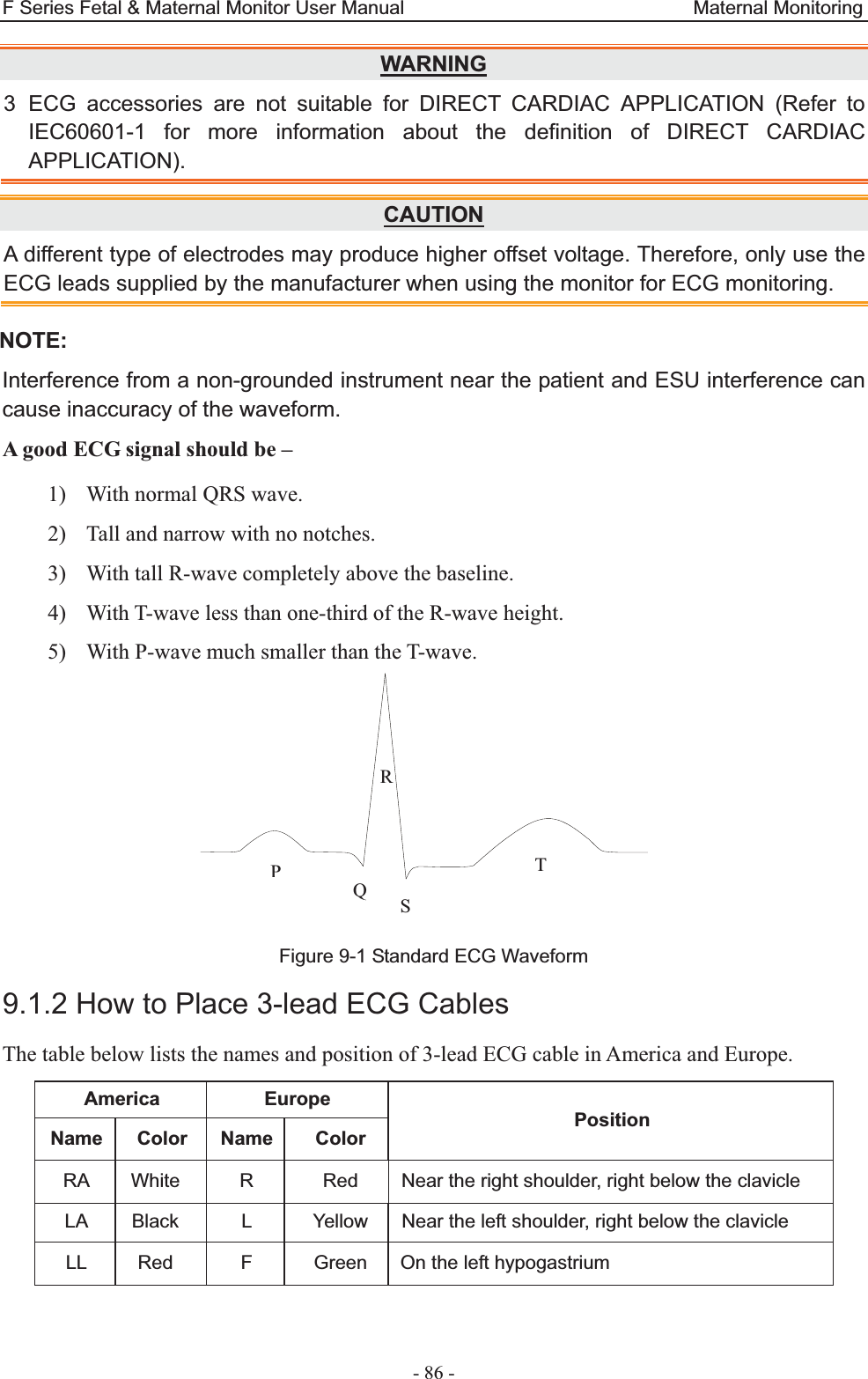
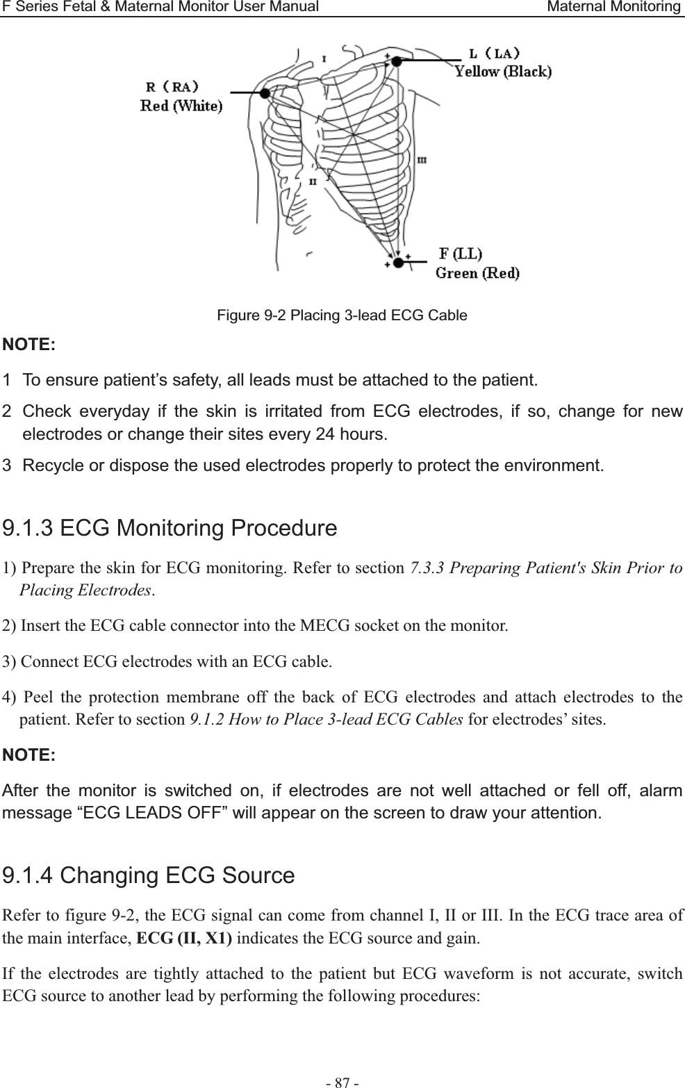
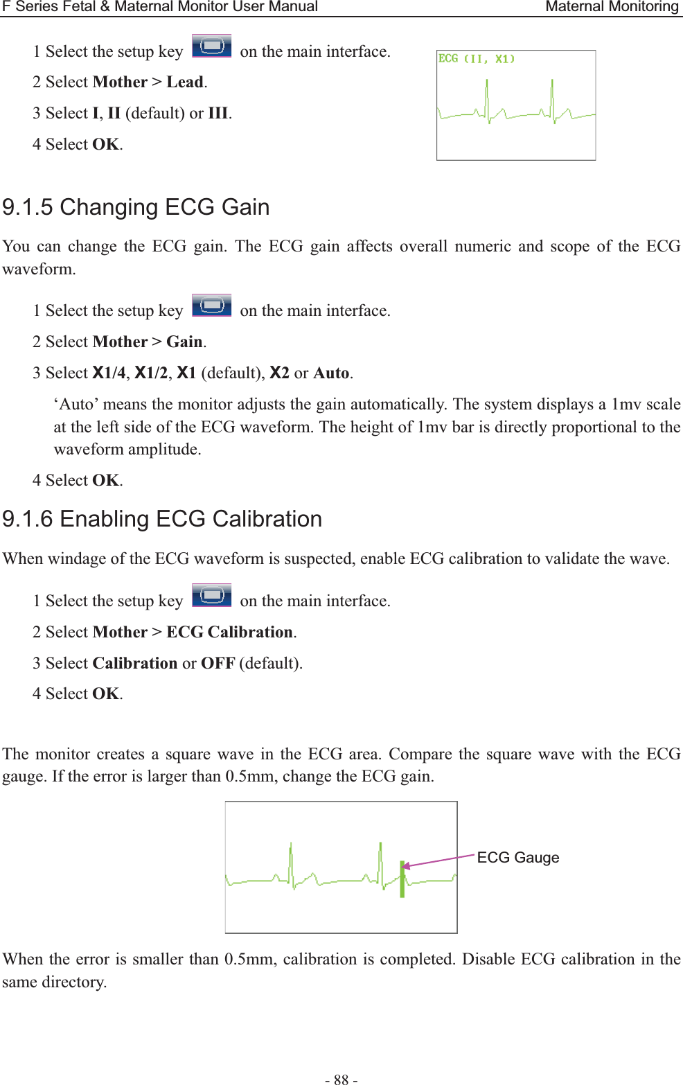
EDAN INSTRUMENTS FTS3UEDAN Fetal Telemetry System User Manual Rev 5
EDAN INSTRUMENTS, INC. Fetal Telemetry System Rev 5
UserManual.wiki
>
EDAN INSTRUMENTS
>
FTS3UEDAN User Manual
User Manual Rev.5
Navigation menu
Upload a User Manual
Namespaces
Wiki Guide
HTML
PDF
Info
Views
User Manual
Discussion / Help
Navigation

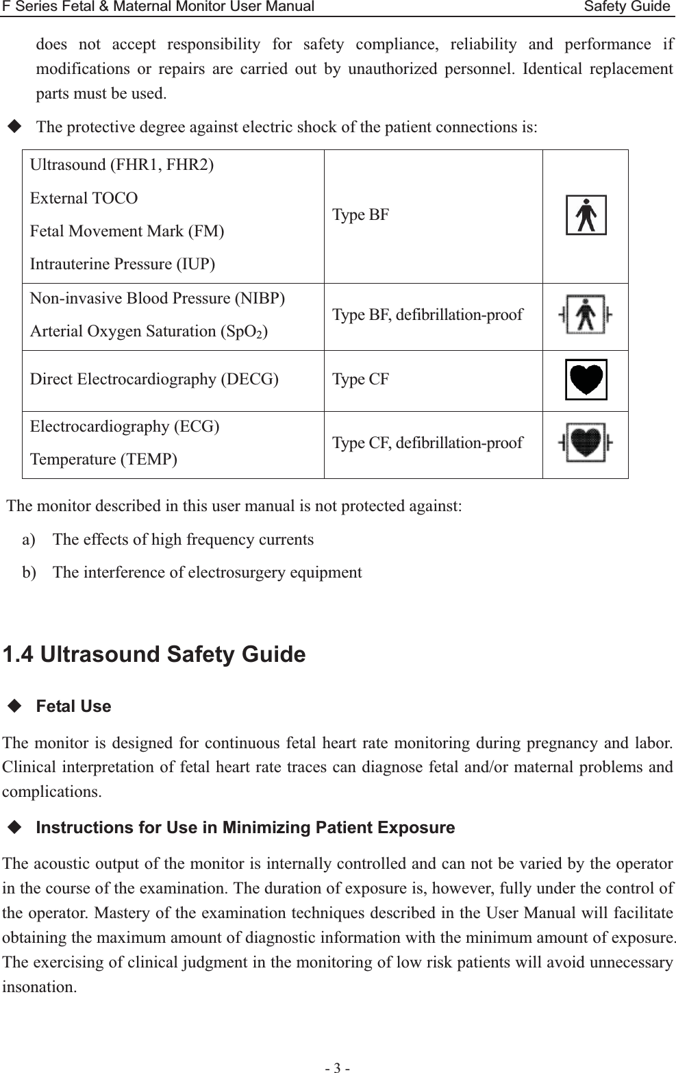
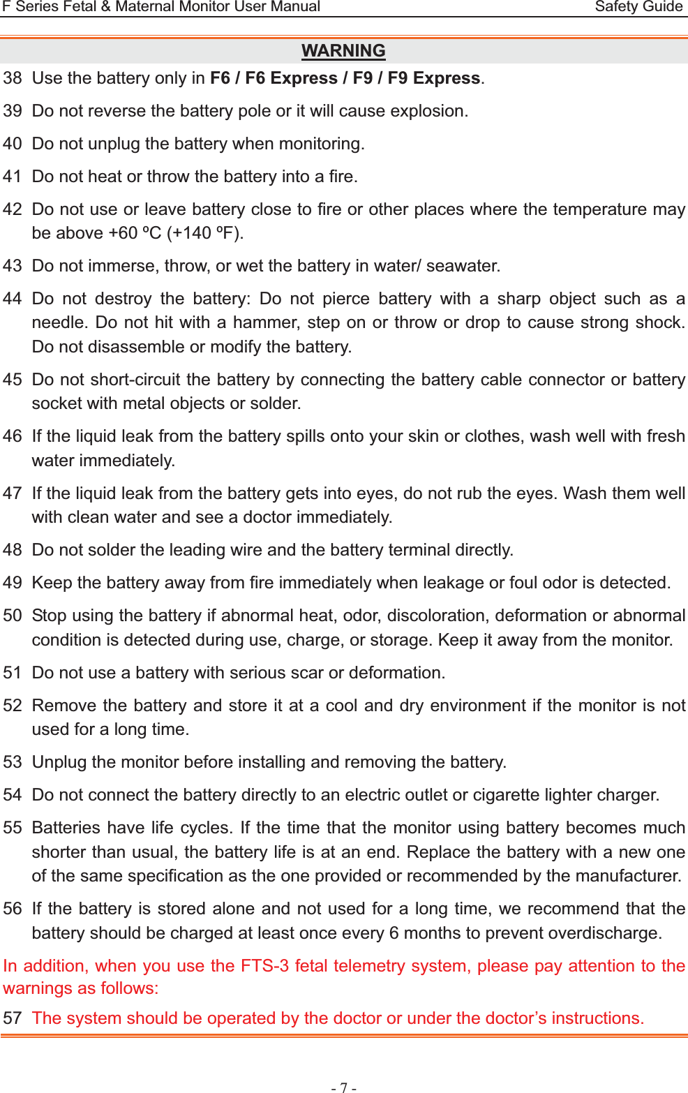


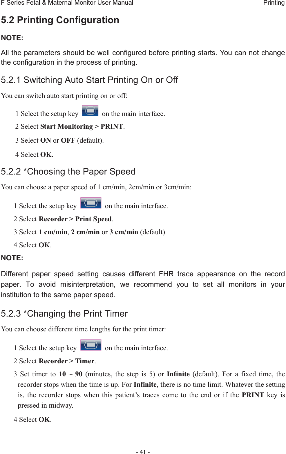

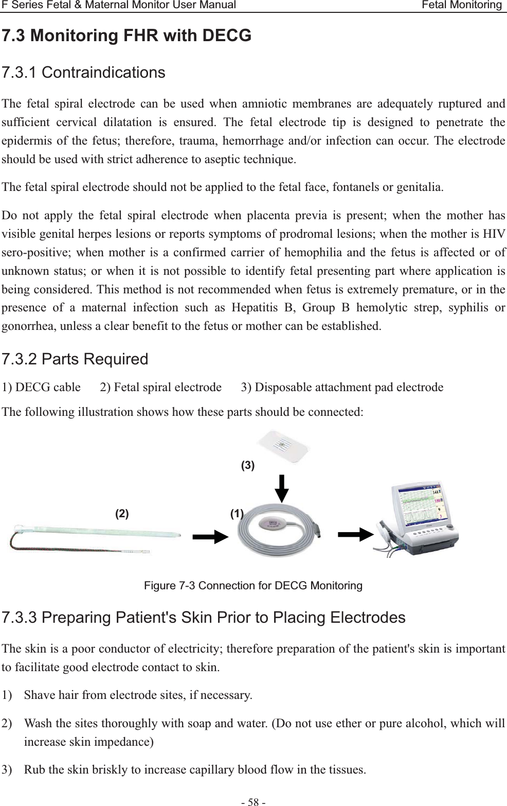
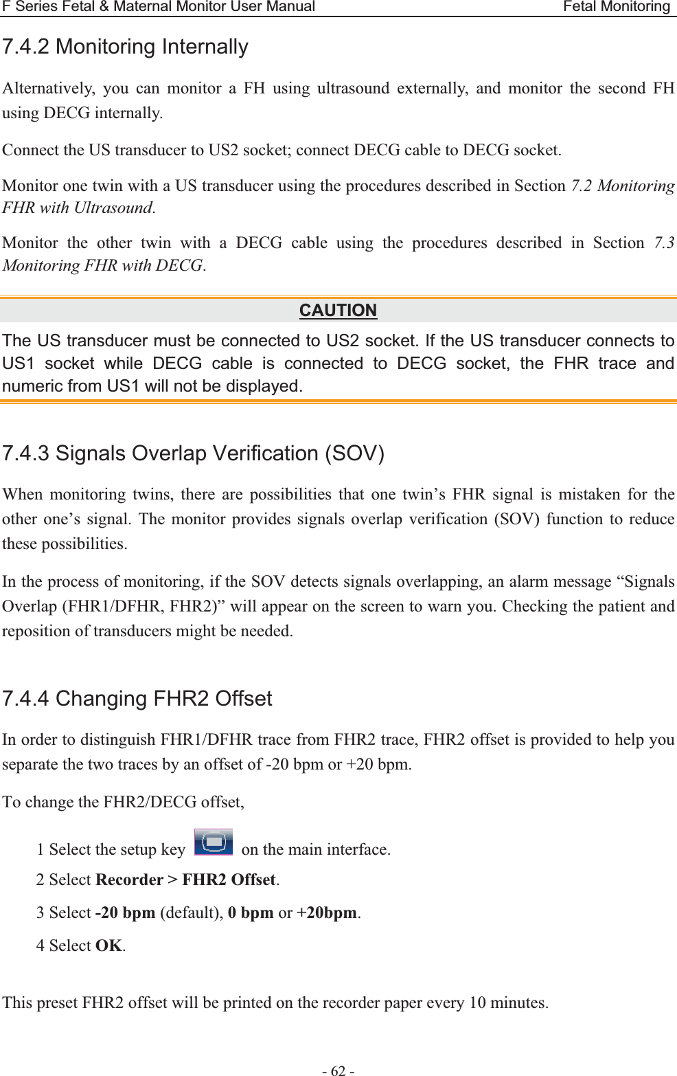
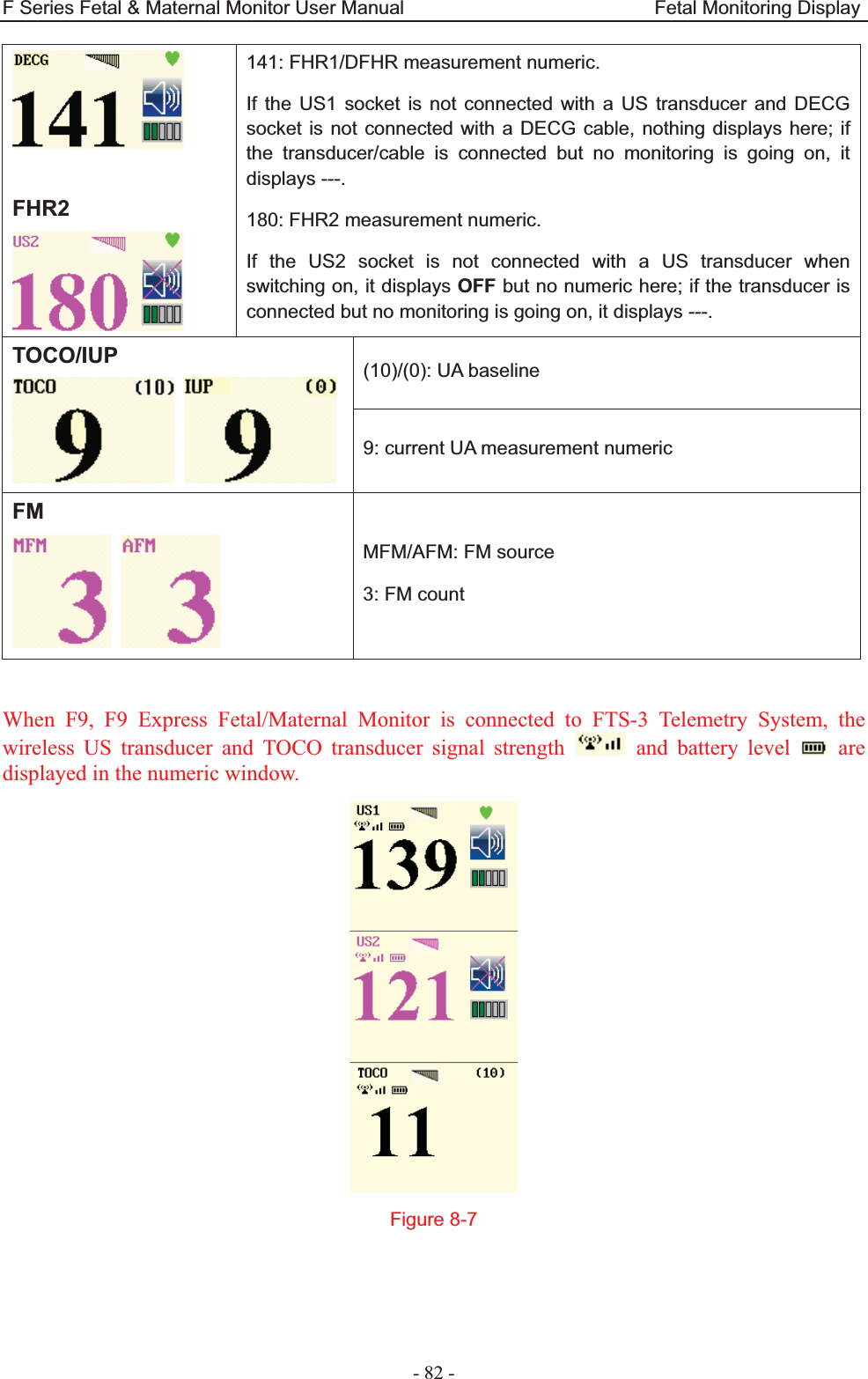

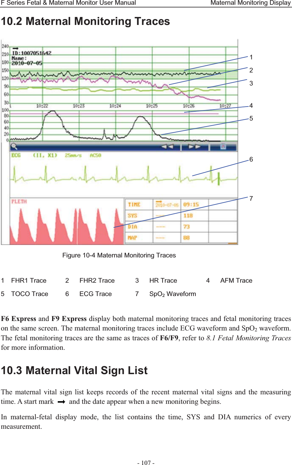
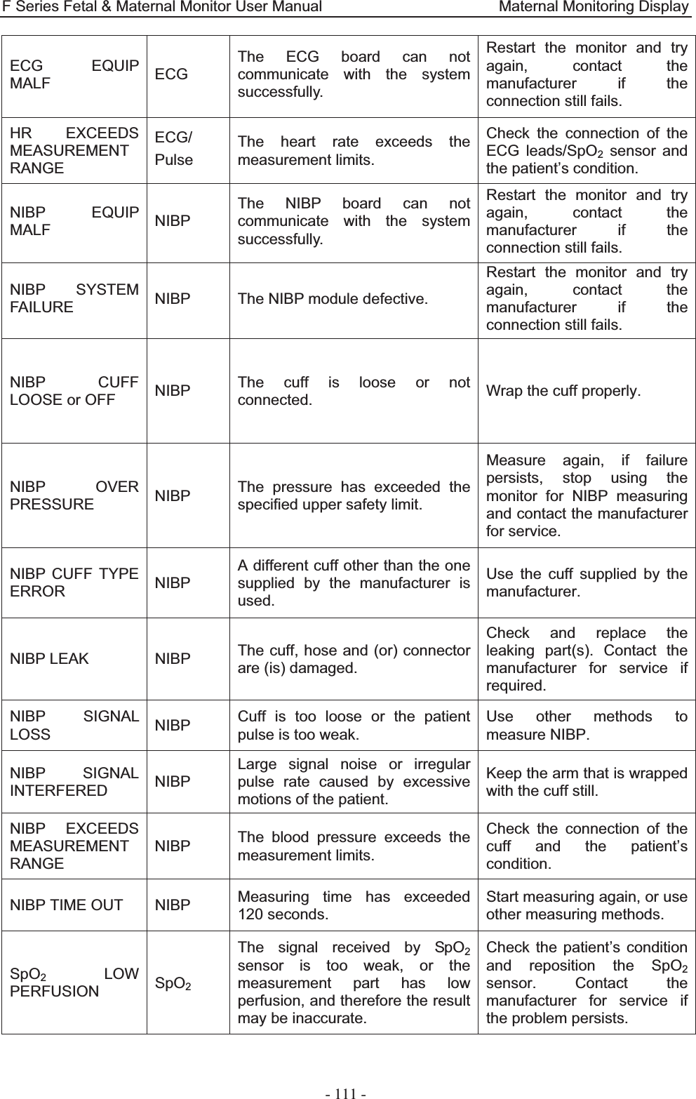
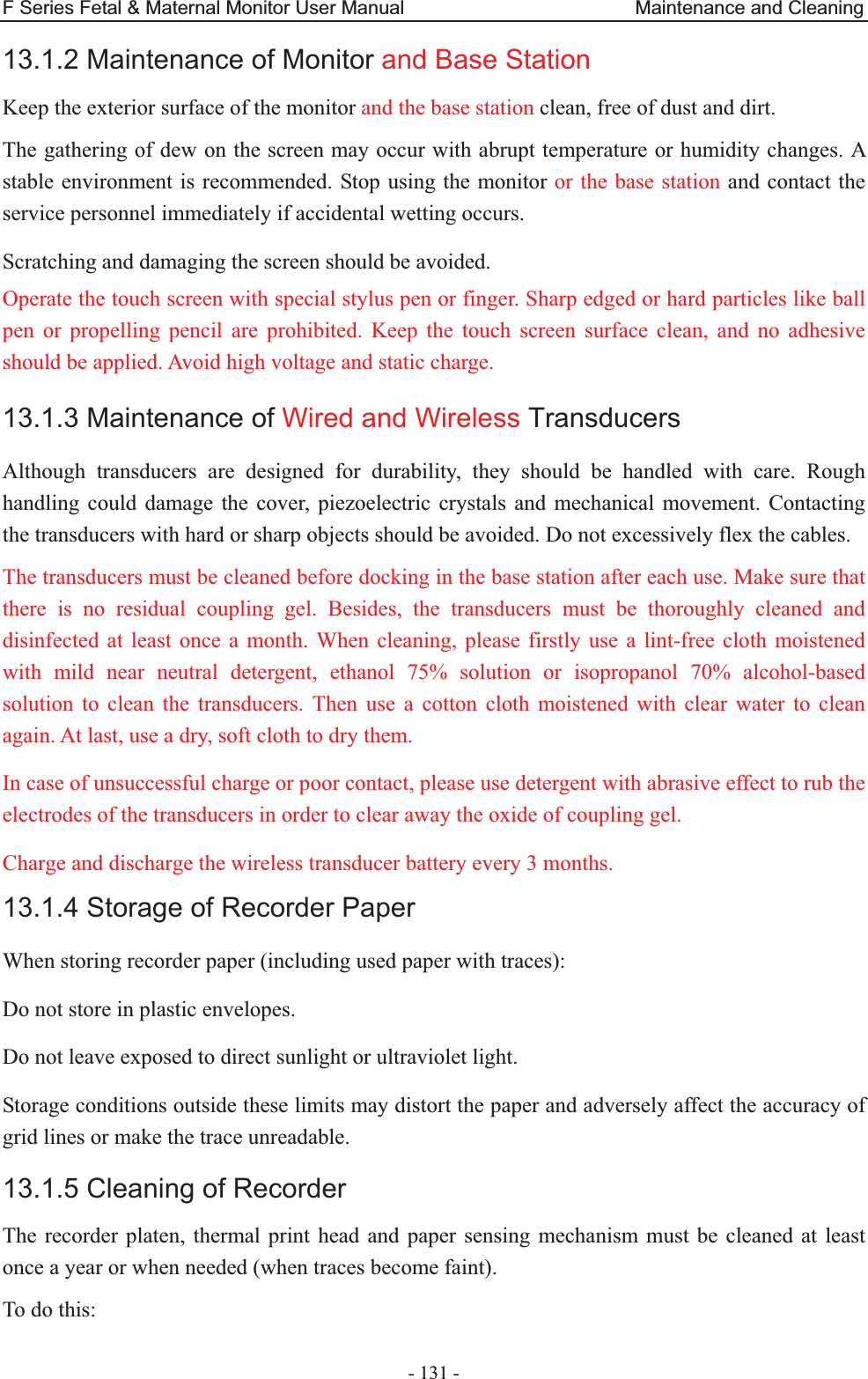
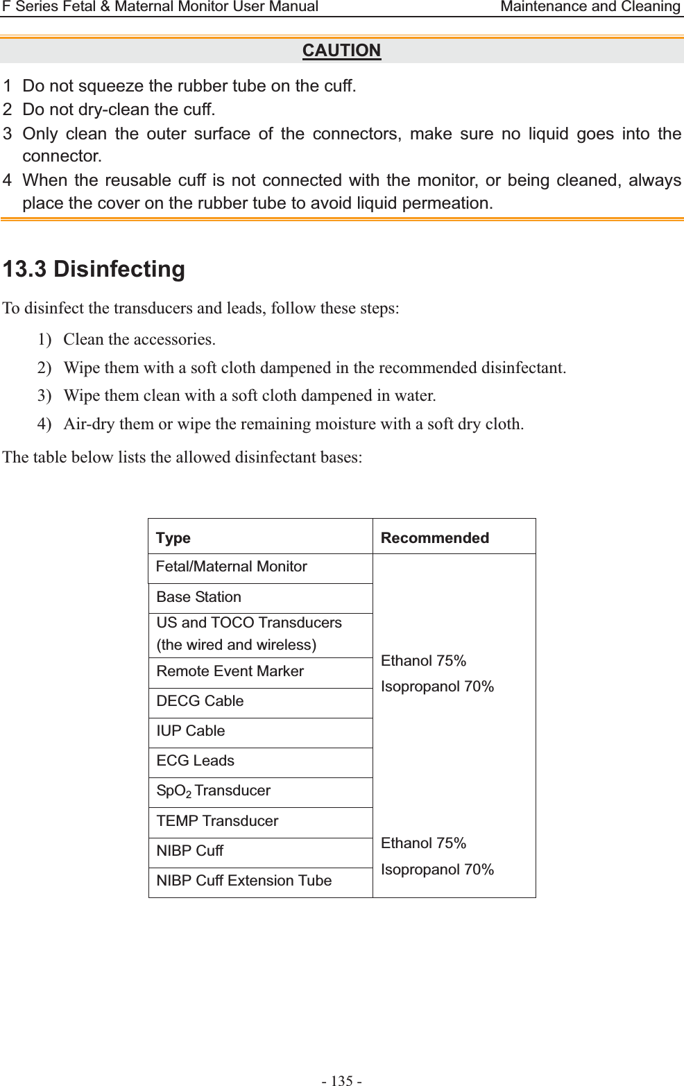
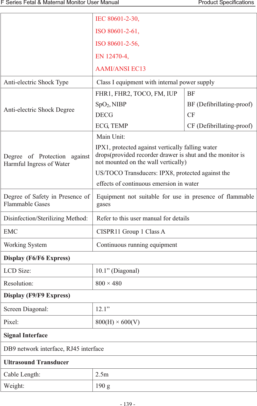
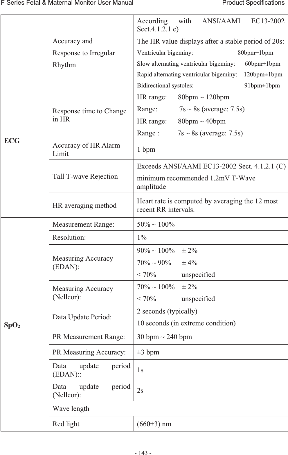
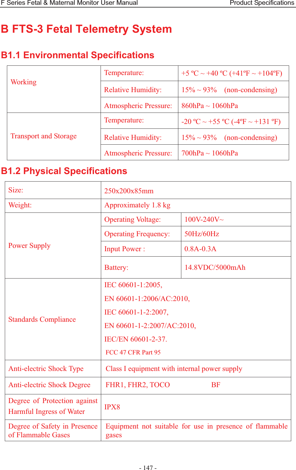
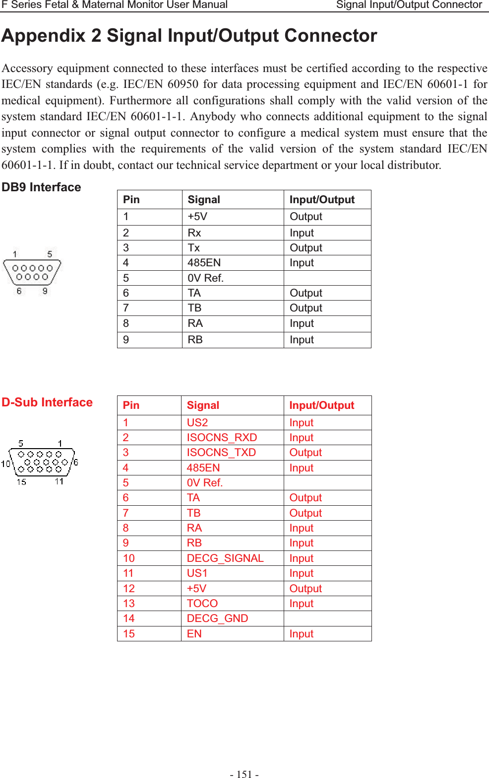
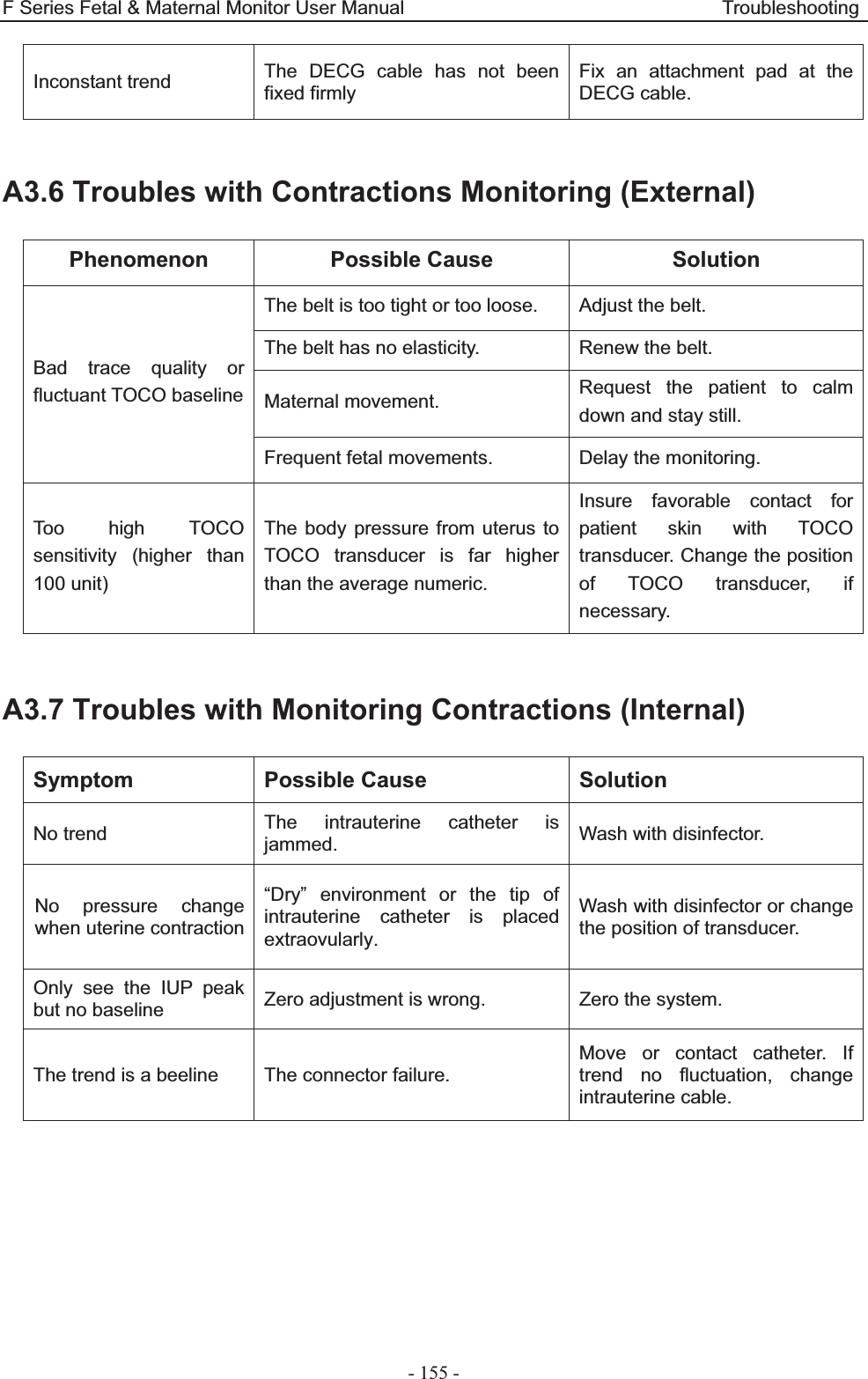
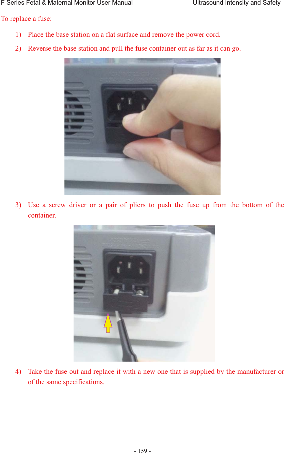
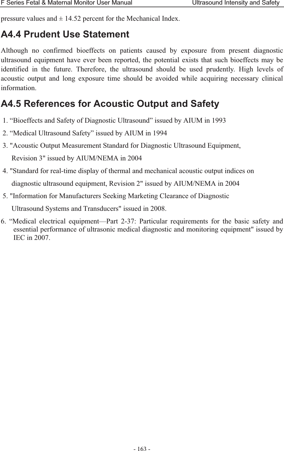
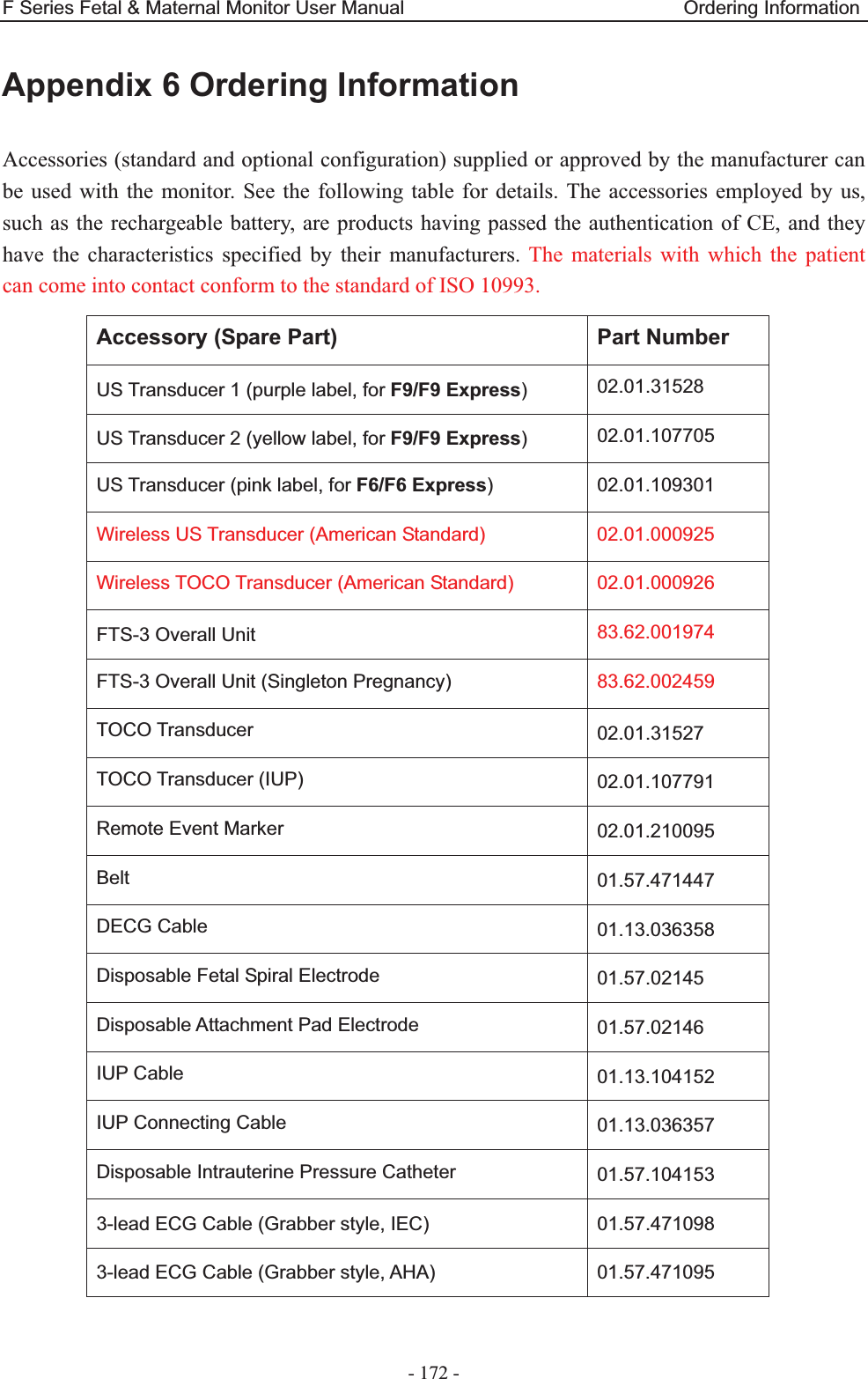
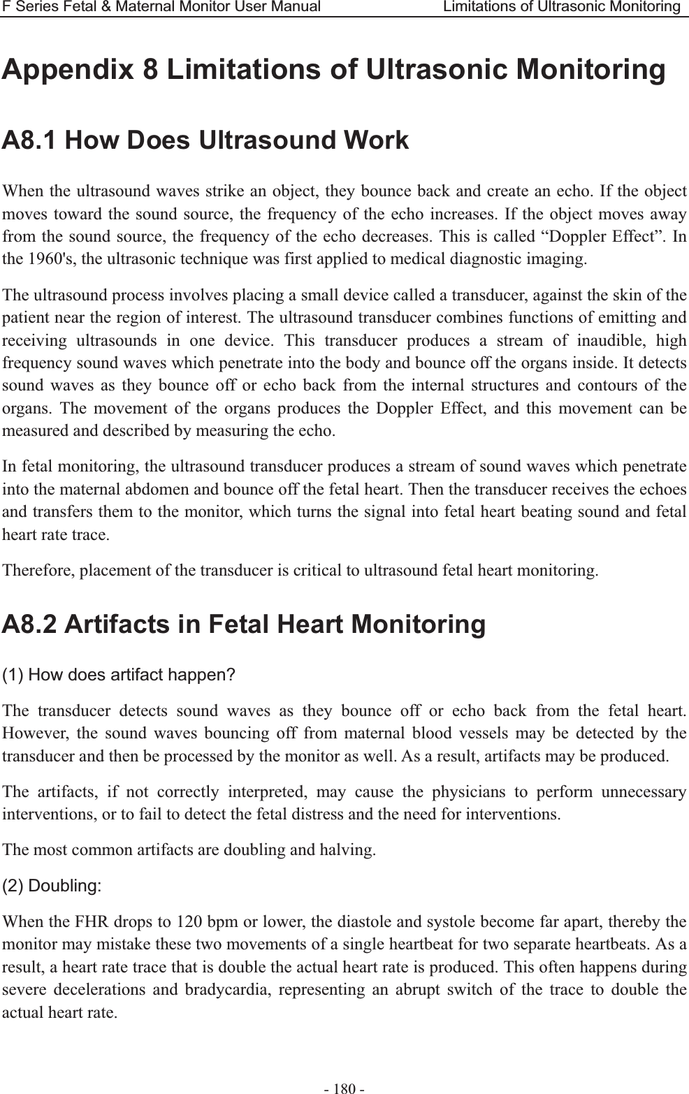
![F Series Fetal & Maternal Monitor User Manual Ultrasound Intensity and Safety - 164 - A4.6 Probe Acoustic Output Parameters List A4.6.1 Test of Wired Probe Acoustic Output Reporting Table (F9/F9 Express)Operating Mode: PW mode Working Frequency: 1.0MHz Index Label MI TIS TIB TIC Scan Non-scan Non-scan Aaprt1 Aaprt>1 Global Maximum Index Value 0.01567 0.008761 0.05723 N/A Associated Acoustic Parameters Pr.a (MPa) 0.01567 P (mW) 11.52 N/A Min of [Pa(Zs),Ita.a(Zs)] (mW) 1.84 Zs (cm) 13.95 Zbp (cm) 5.188 Zb (cm) 13.60 Z at max Ipi.a (cm) 13.80 13.80 deq(Zb) (cm) 1.75 fawf (MHz) 1.00 1.00 1.00 N/A Dim of Aaprt X (cm) ĭ3.46 ĭ3.46 N/A Y (cm) ĭ3.46 ĭ3.46 N/A Other Information td (usec) 88.72 prr (Hz) 2000 Pr at max Ipi (MPa) 0.02930 Deq at max Ipi (cm) 1.73 Ipi.3 at max MI (W/cm2) 0.01025 Focal Length Flx (cm) N/A Fly (cm) N/A Operating Control Conditions Focus(mm) Fixed Depth(mm) Fixed Freq(MHz) 1.0](https://usermanual.wiki/EDAN-INSTRUMENTS/FTS3UEDAN/User-Guide-2533650-Page-175.png)
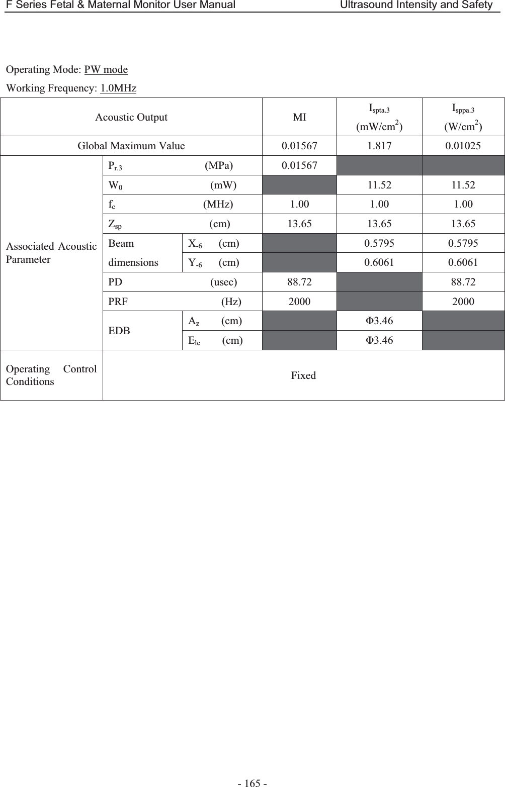
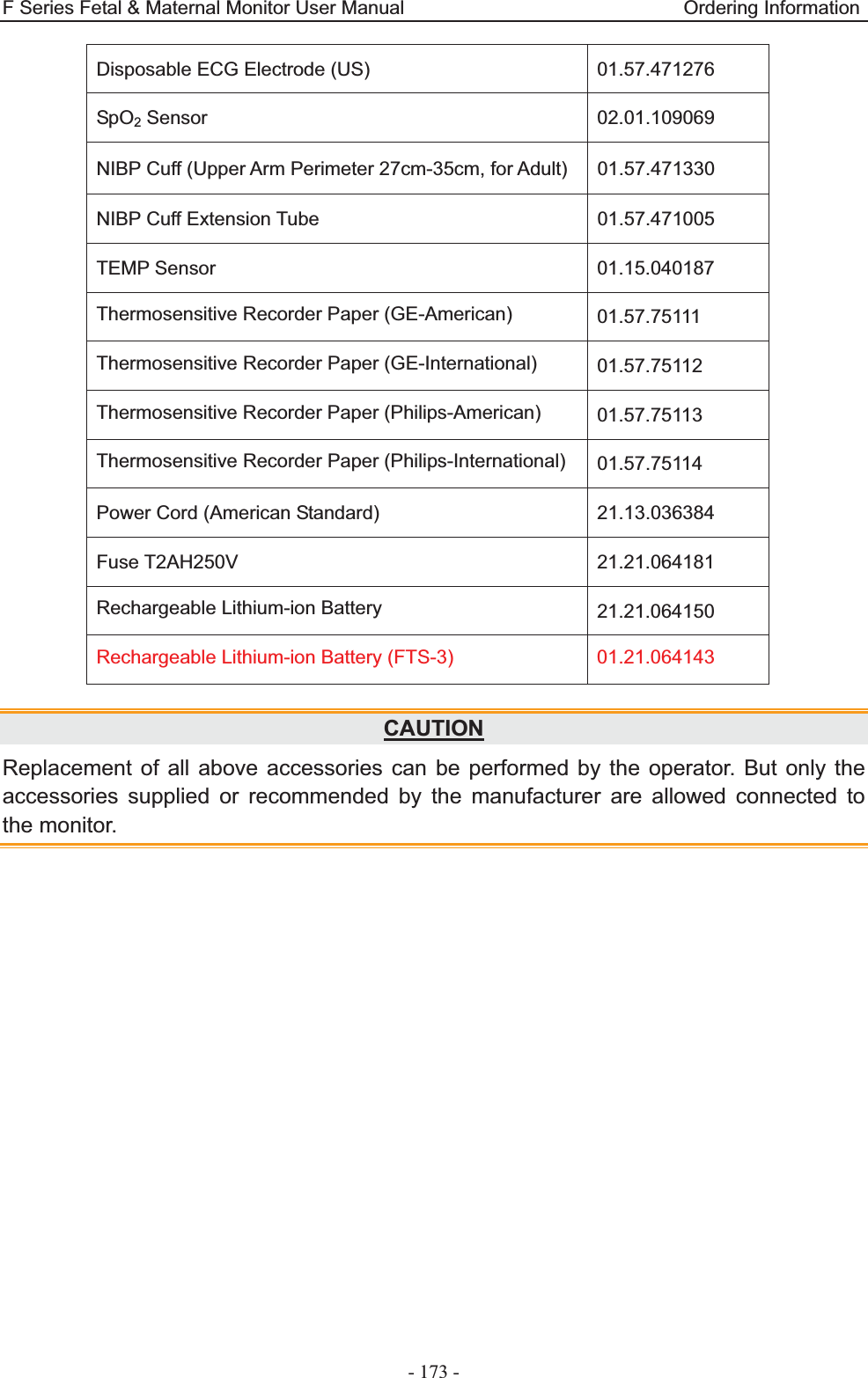
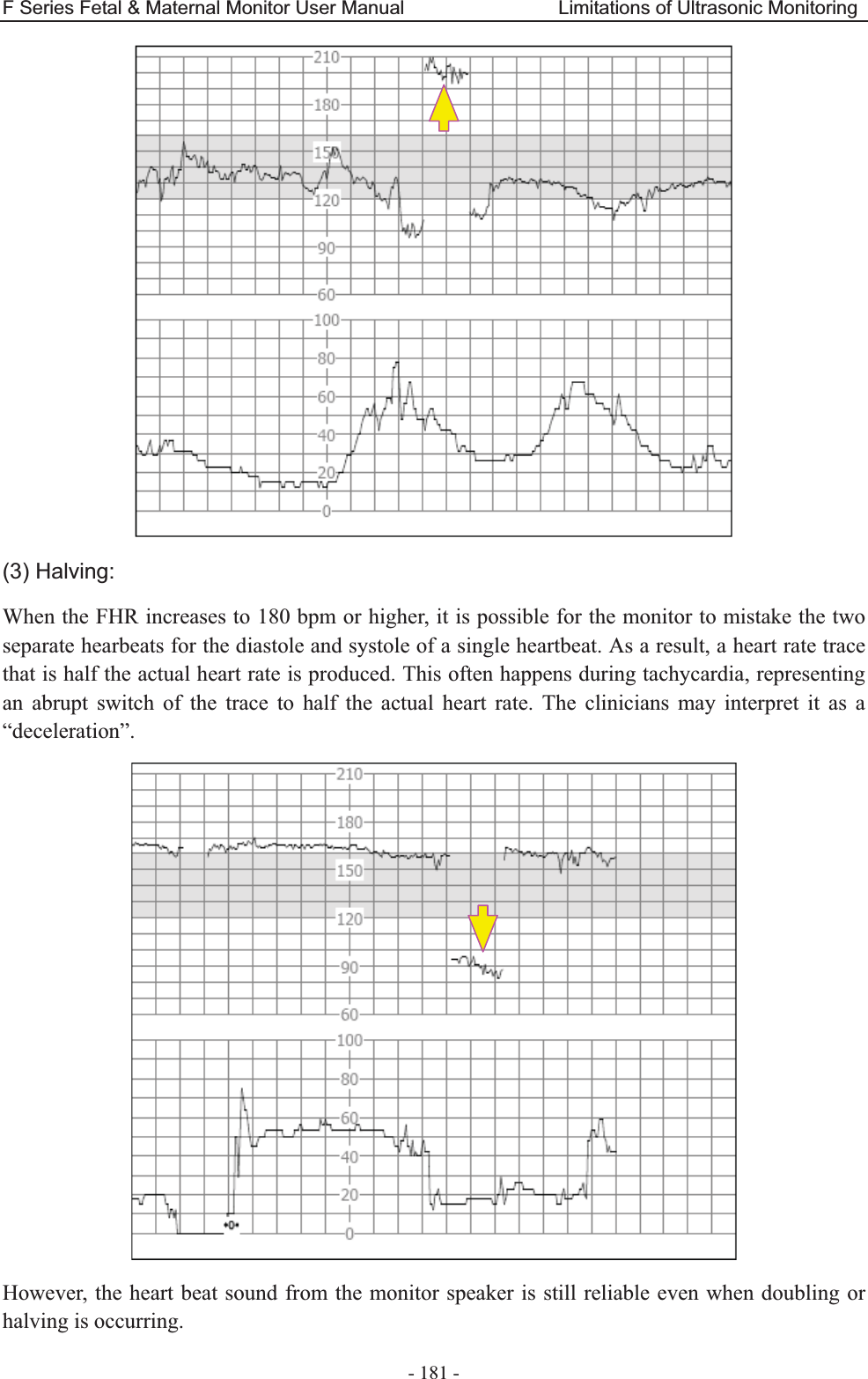
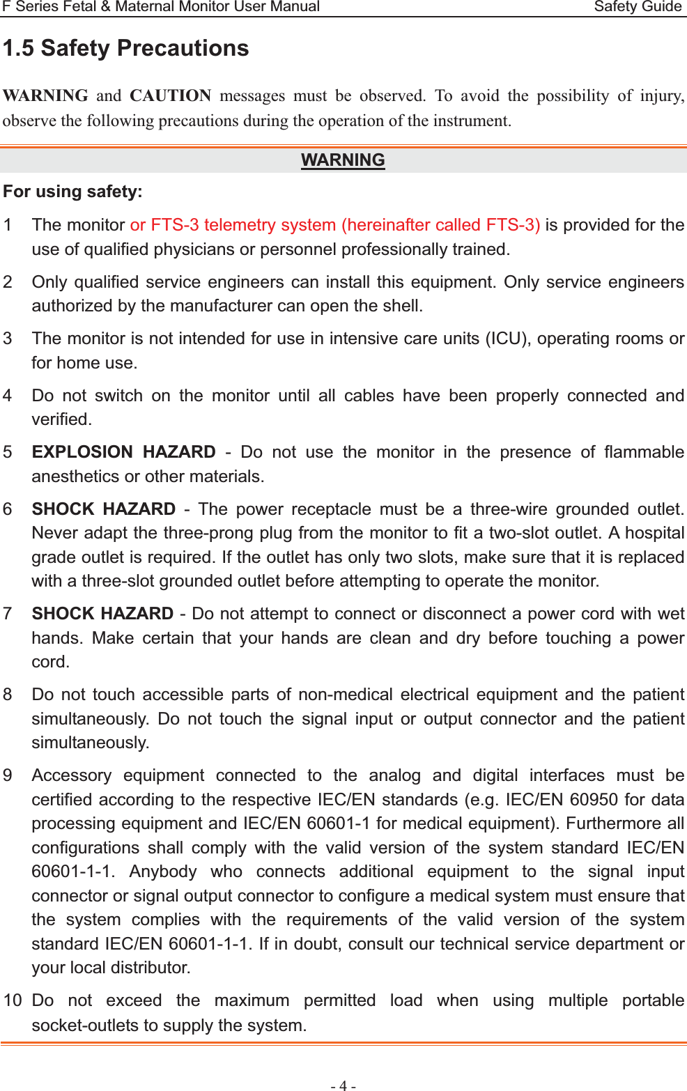
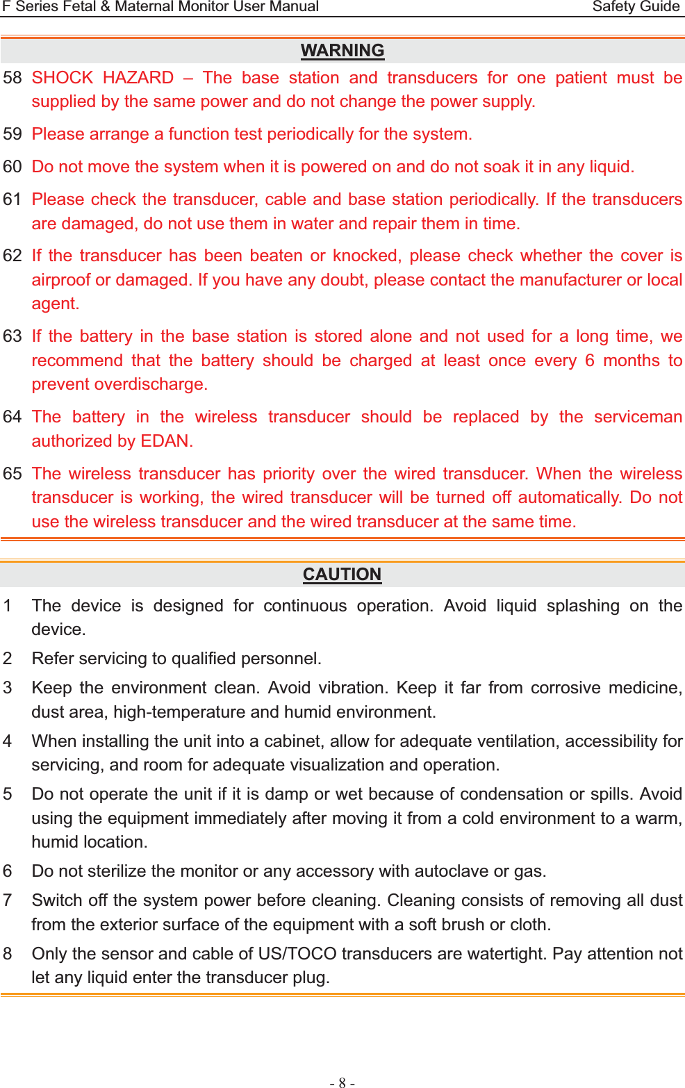
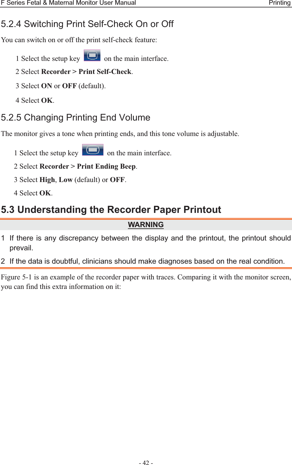
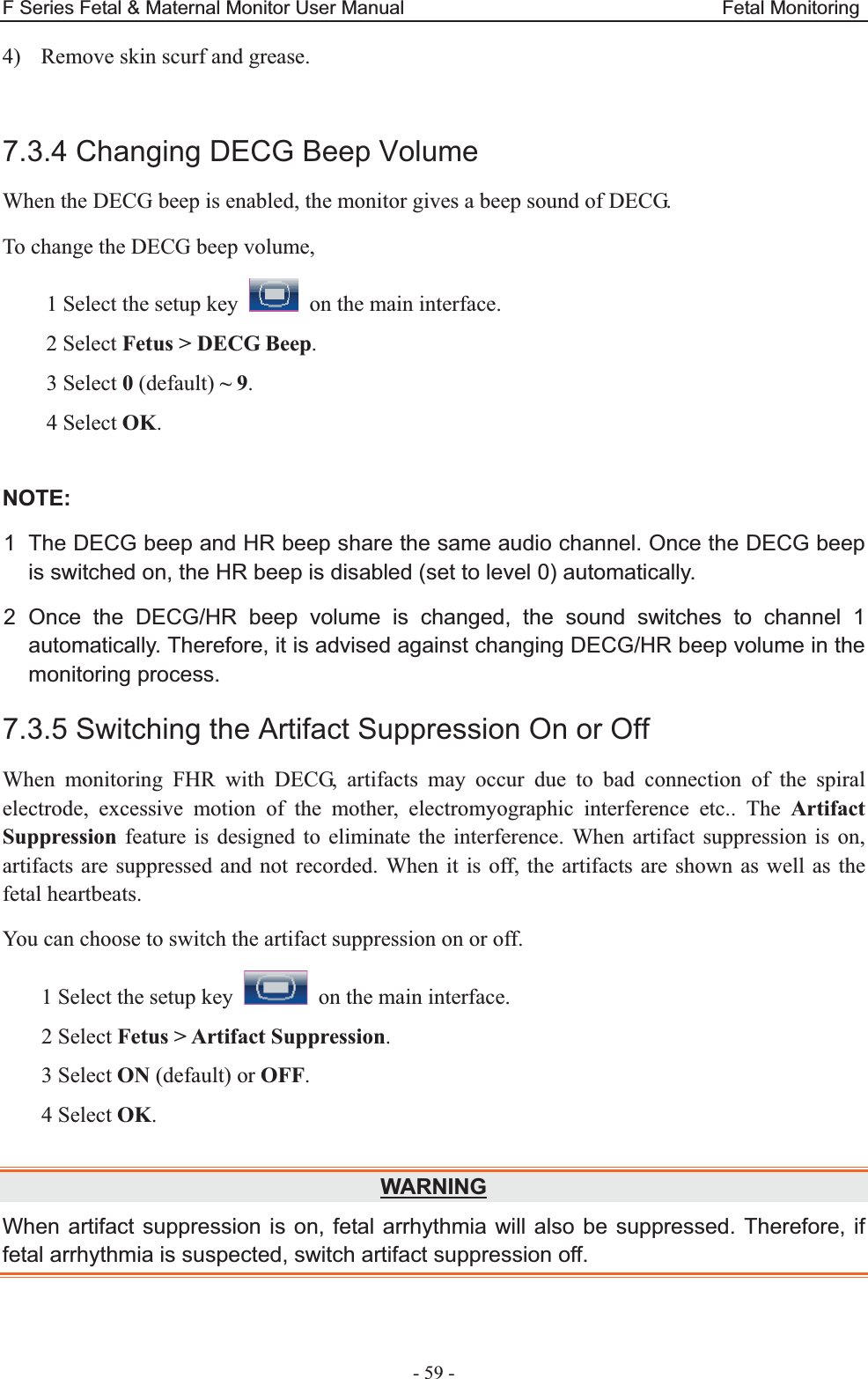
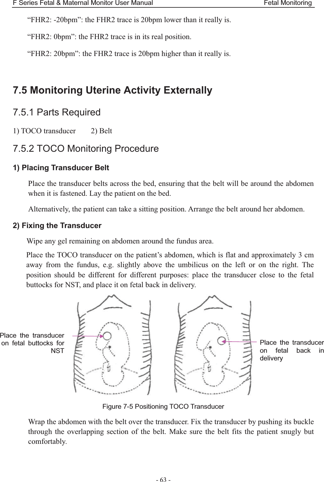
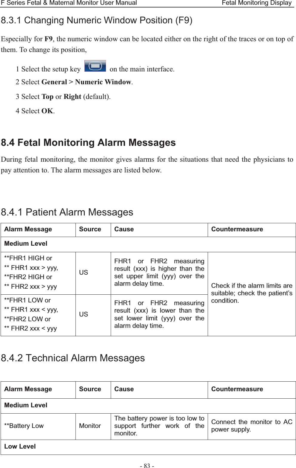
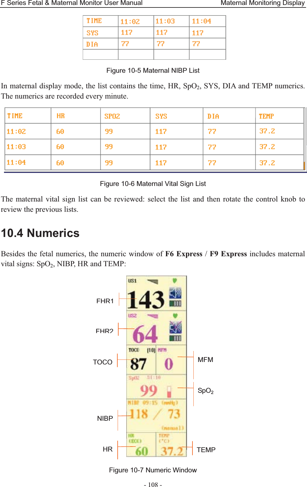
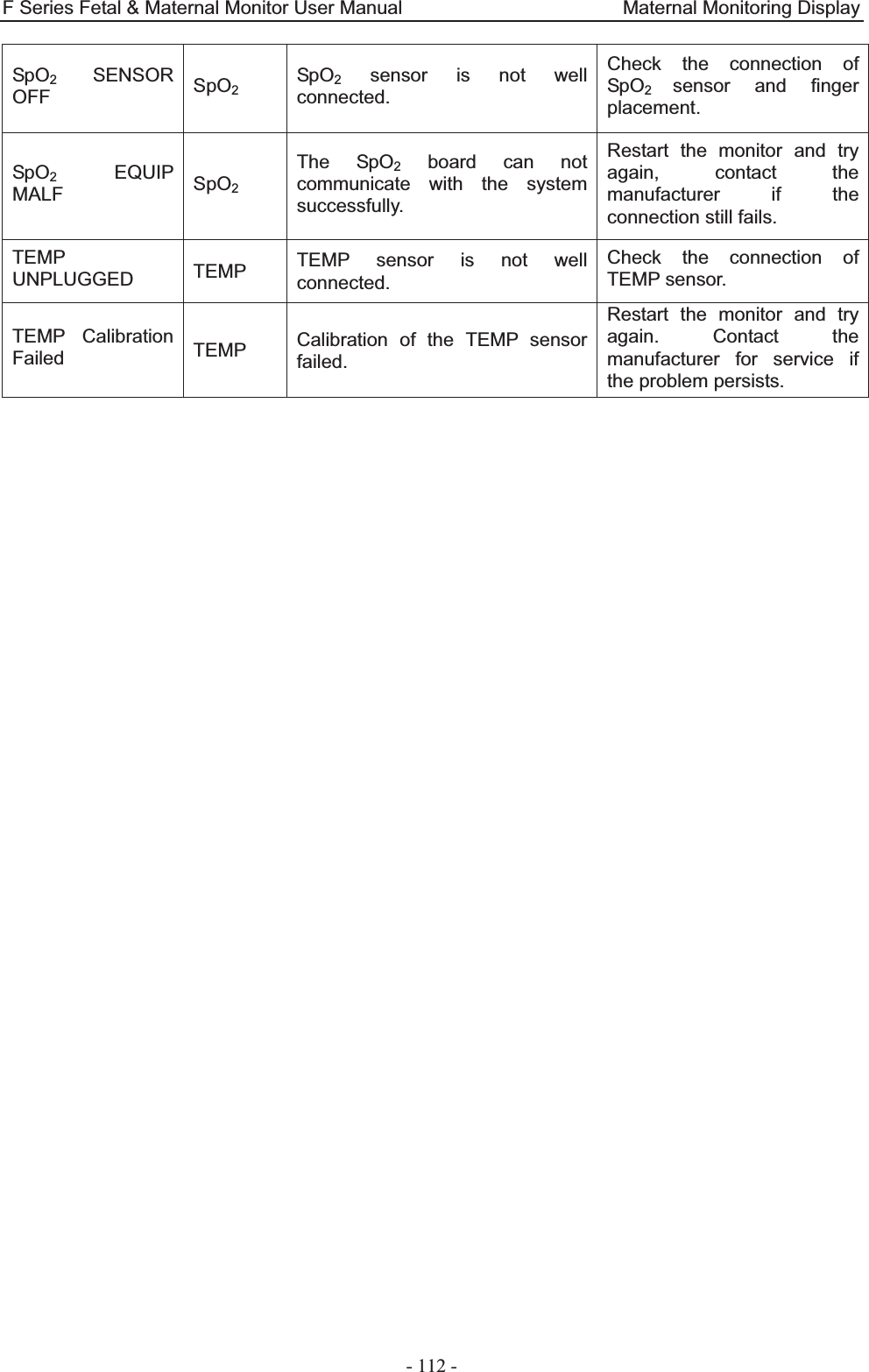
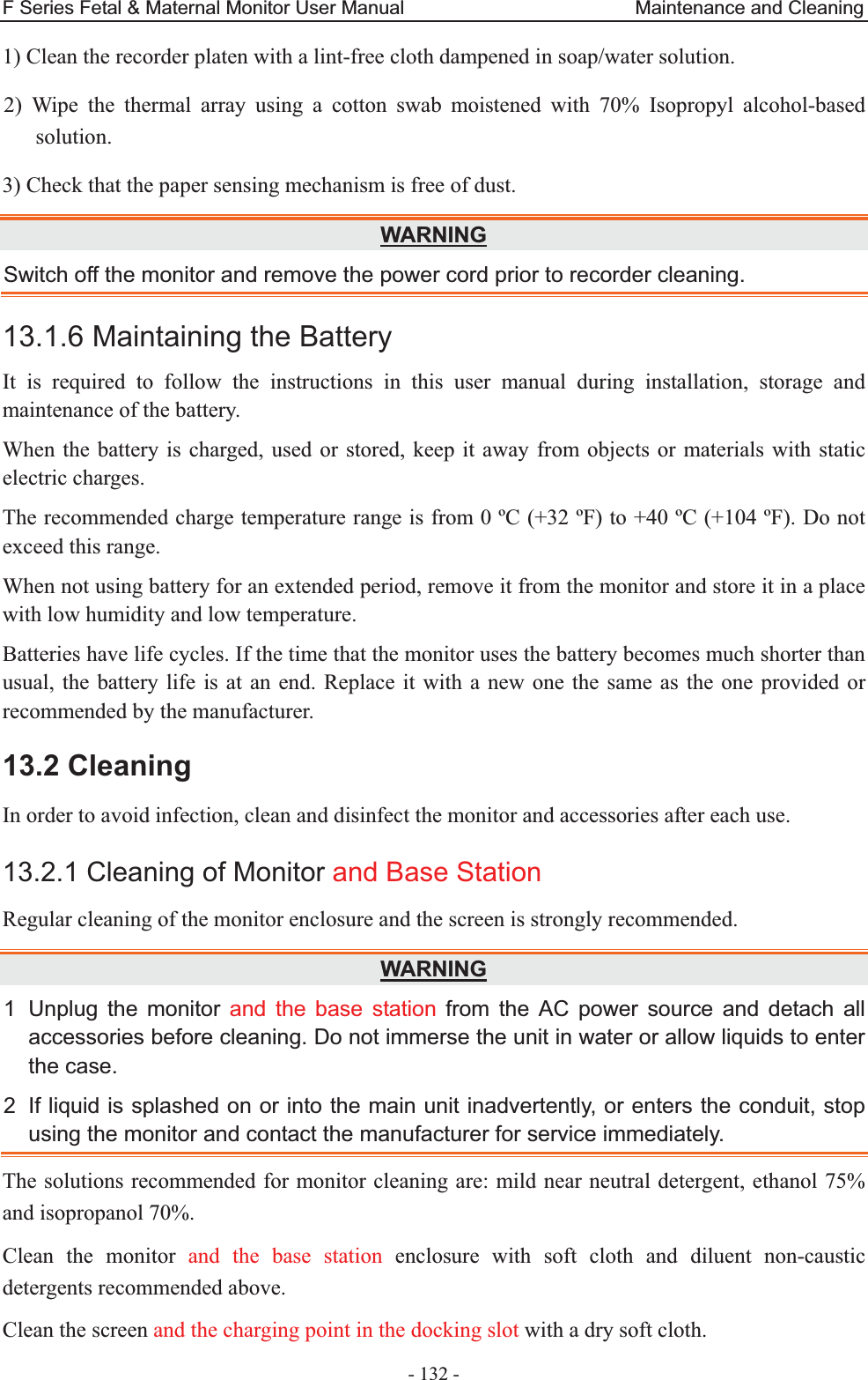
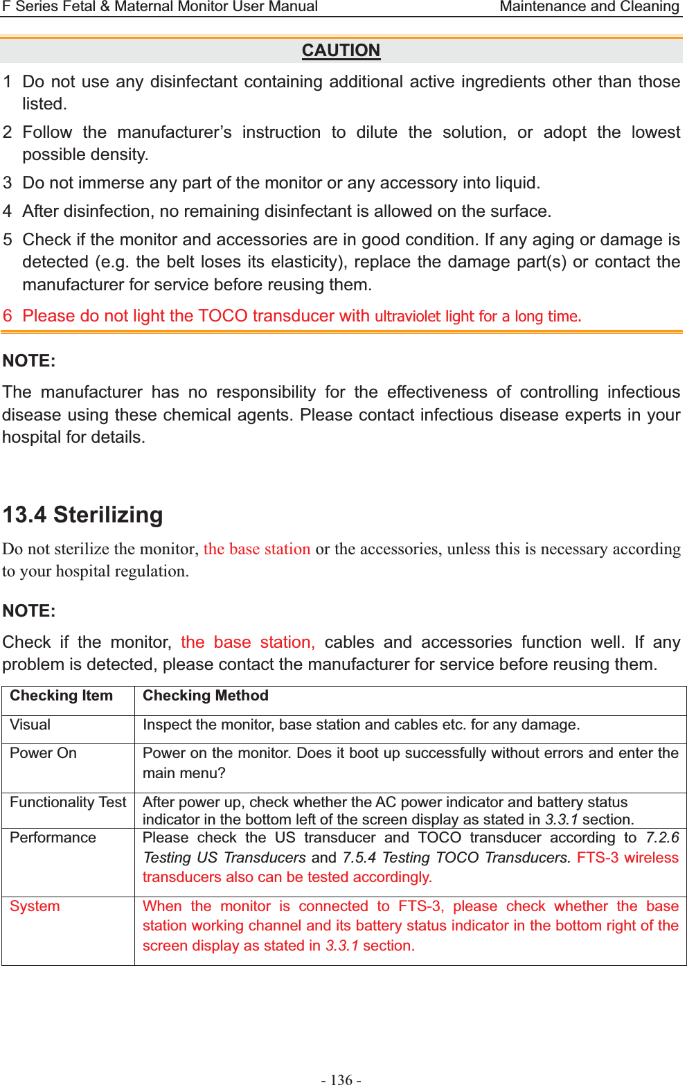
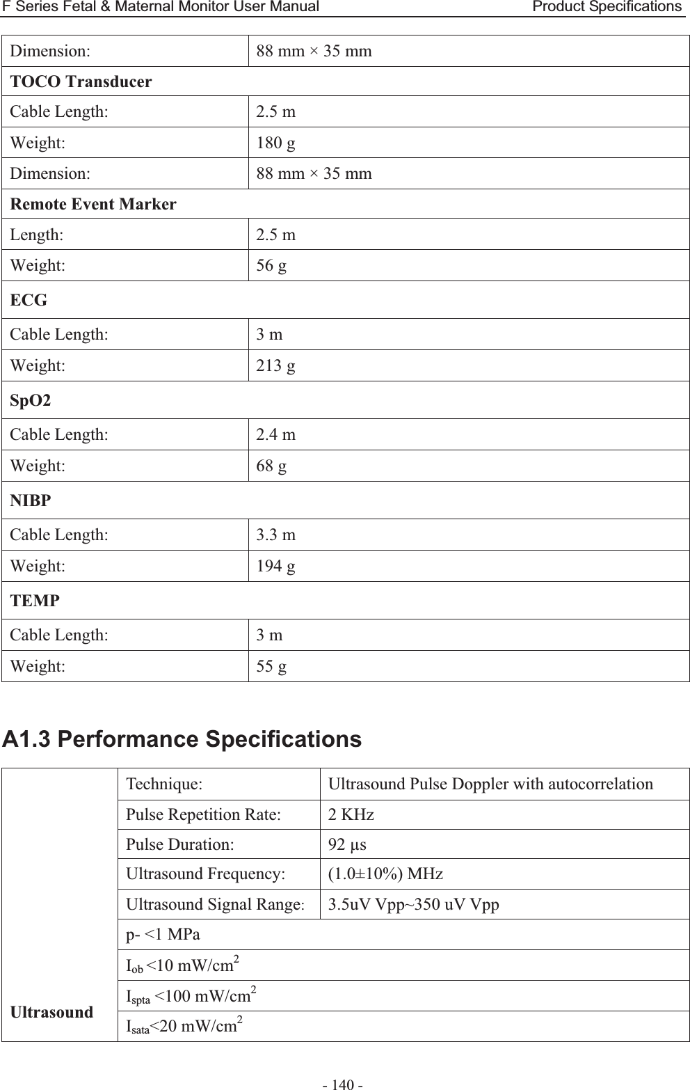
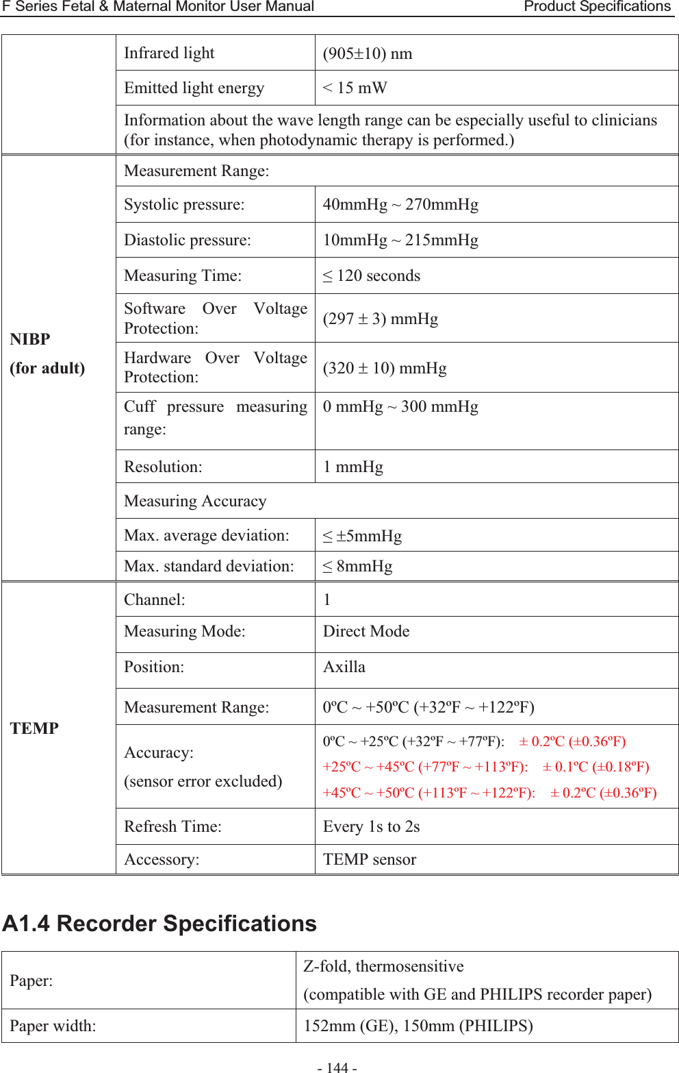
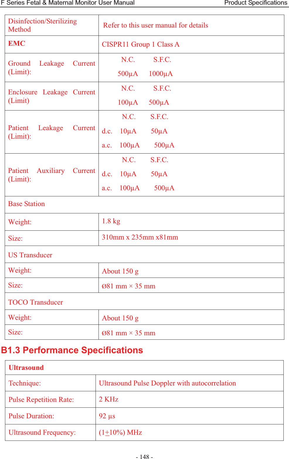
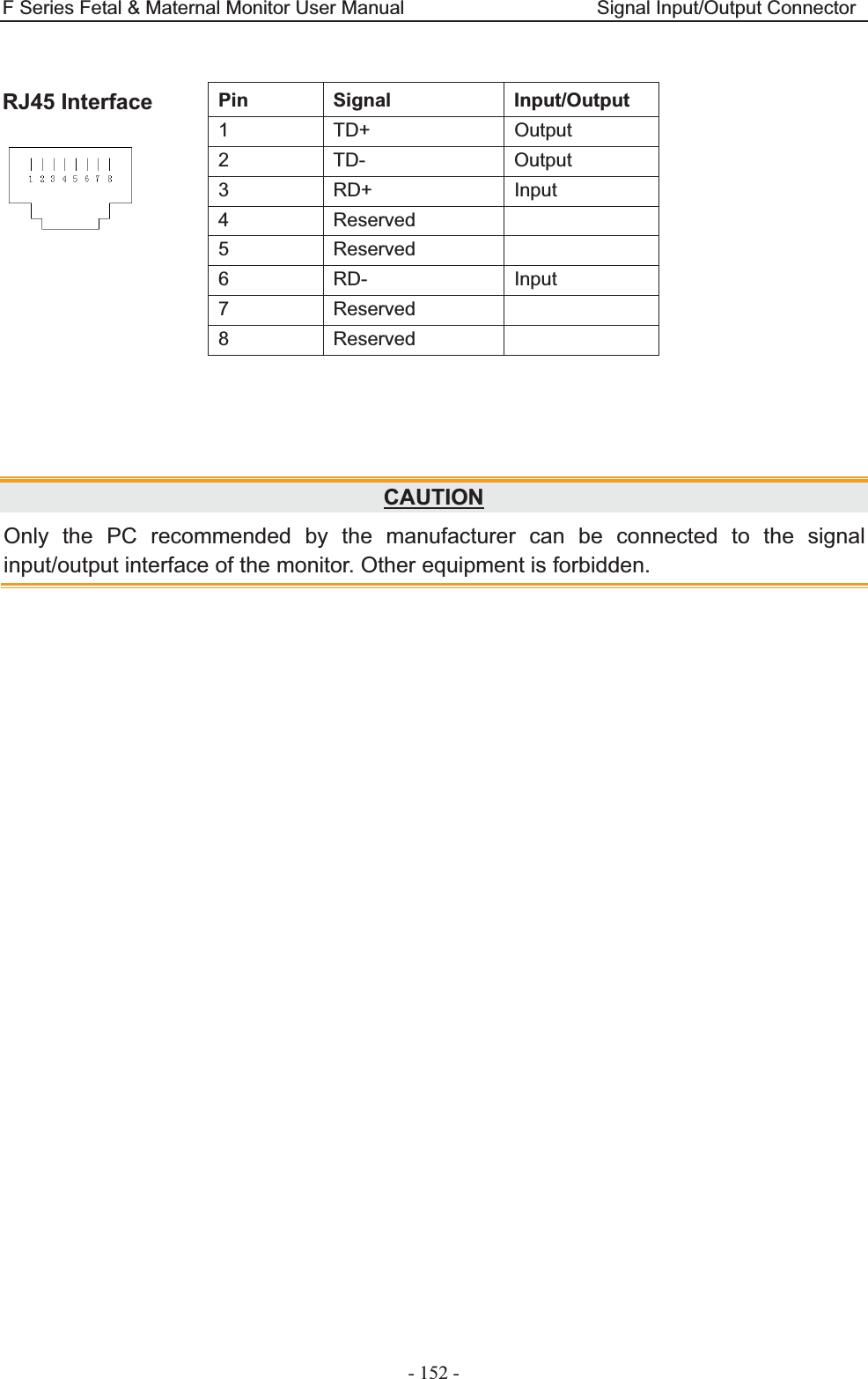
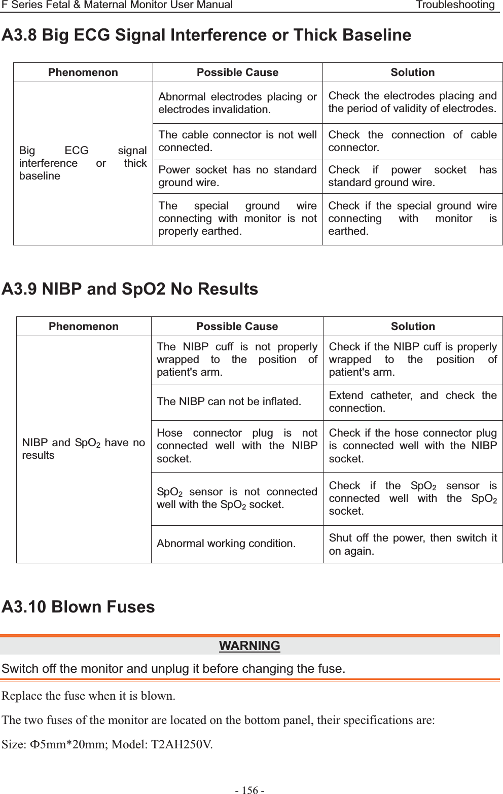
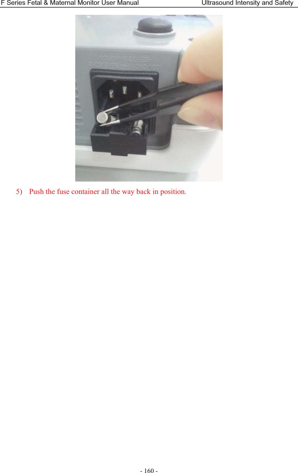
![F Series Fetal & Maternal Monitor User Manual Ultrasound Intensity and Safety - 166 - Acoustic Output Reporting Table (F6/F6 Express) Operating Mode: PW mode Working Frequency: 1.0MHz Index Label MI TIS TIB TIC Scan Non-scan Non-scan Aaprt1 Aaprt>1 Global Maximum Index Value 0.01405 0.006149 0.04687 N/A Associated Acoustic Parameters Pr.a (MPa) 0.01405 P (mW) 10.70 N/A Min of [Pa(Zs),Ita.a(Zs)] (mW) 1.29 Zs (cm) 13.45 Zbp (cm) 4.236 Zb (cm) 13.35 Z at max Ipi.a (cm) 13.45 13.45 deq(Zb) (cm) 2.04 fawf (MHz) 1.00 1.00 1.00 N/A Dim of Aaprt X (cm) ĭ2.83 ĭ2.83 N/A Y (cm) ĭ2.83 ĭ2.83 N/A Other Information td (usec) 89.36 prr (Hz) 2000 Pr at max Ipi (MPa) 0.0229 Deq at max Ipi (cm) 2.04 Ipi.3 at max MI (W/cm2) 0.007225 Focal Length Flx (cm) N/A Fly (cm) N/A Operating Control Conditions Focus(mm) Fixed Depth(mm) Fixed Freq(MHz) 1.0](https://usermanual.wiki/EDAN-INSTRUMENTS/FTS3UEDAN/User-Guide-2533650-Page-177.png)

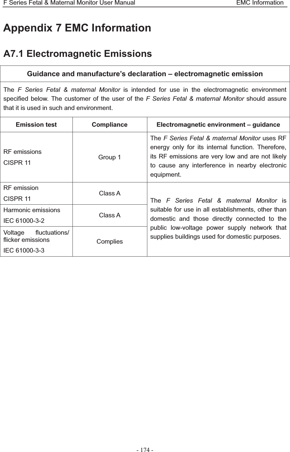
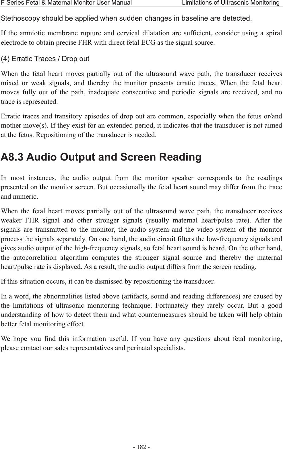
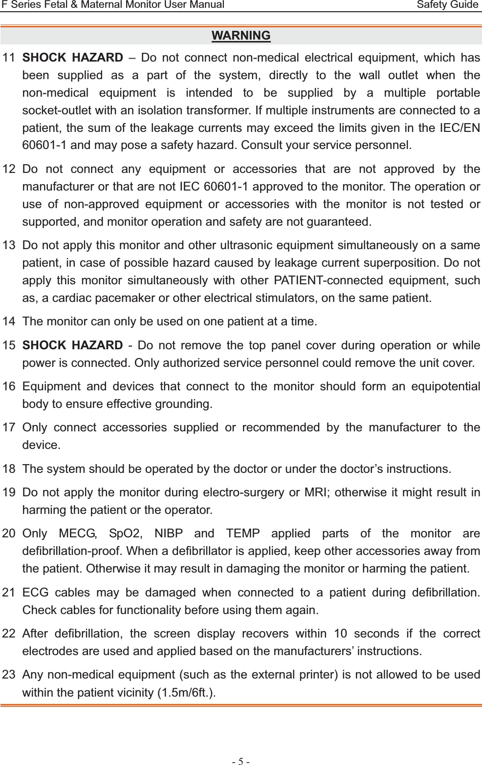
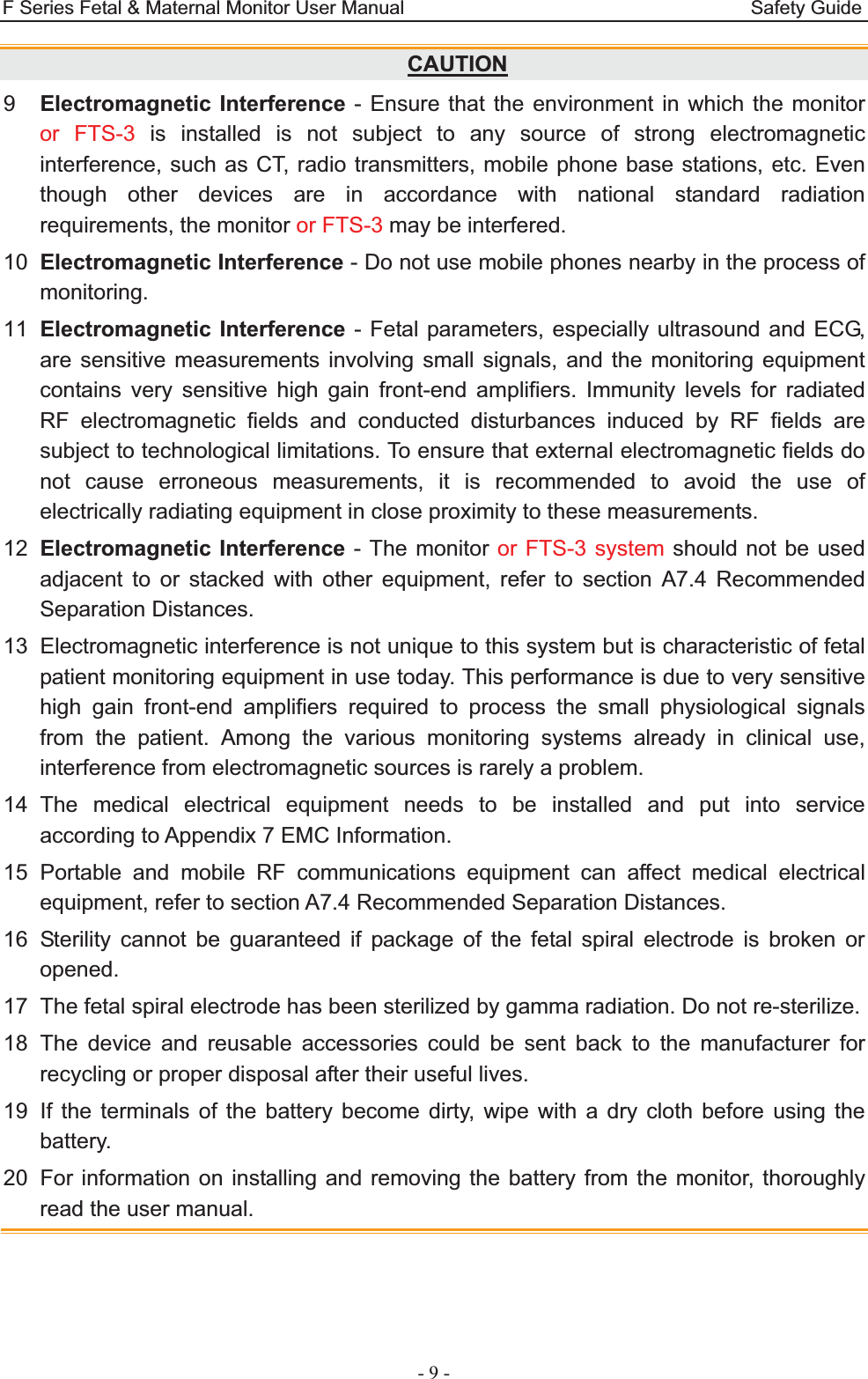
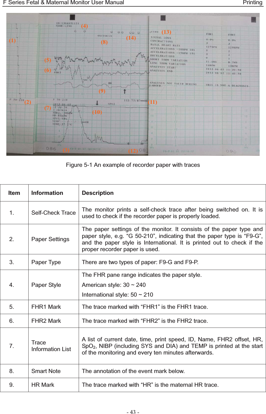
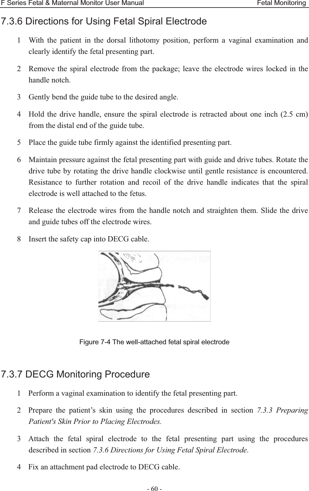
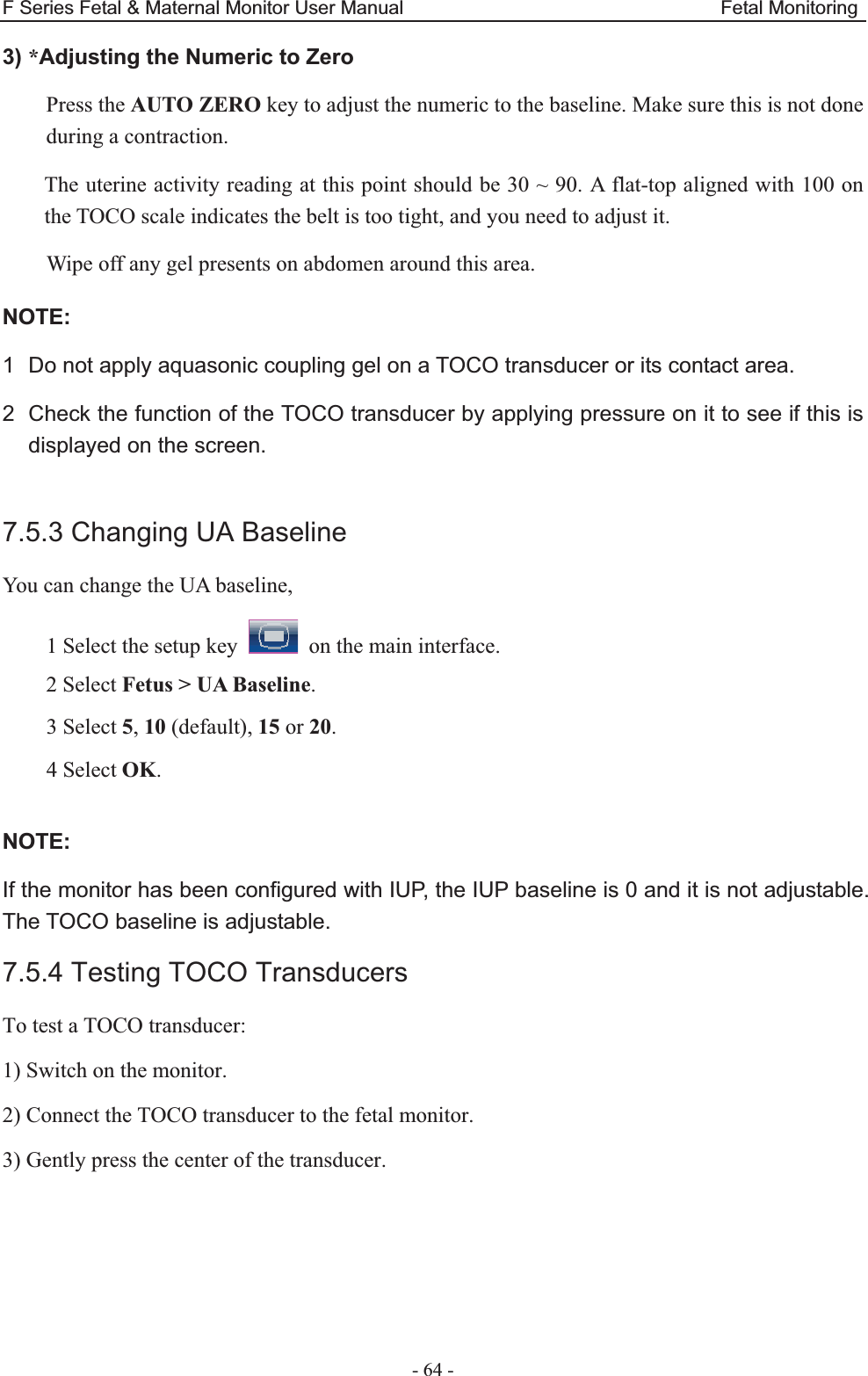
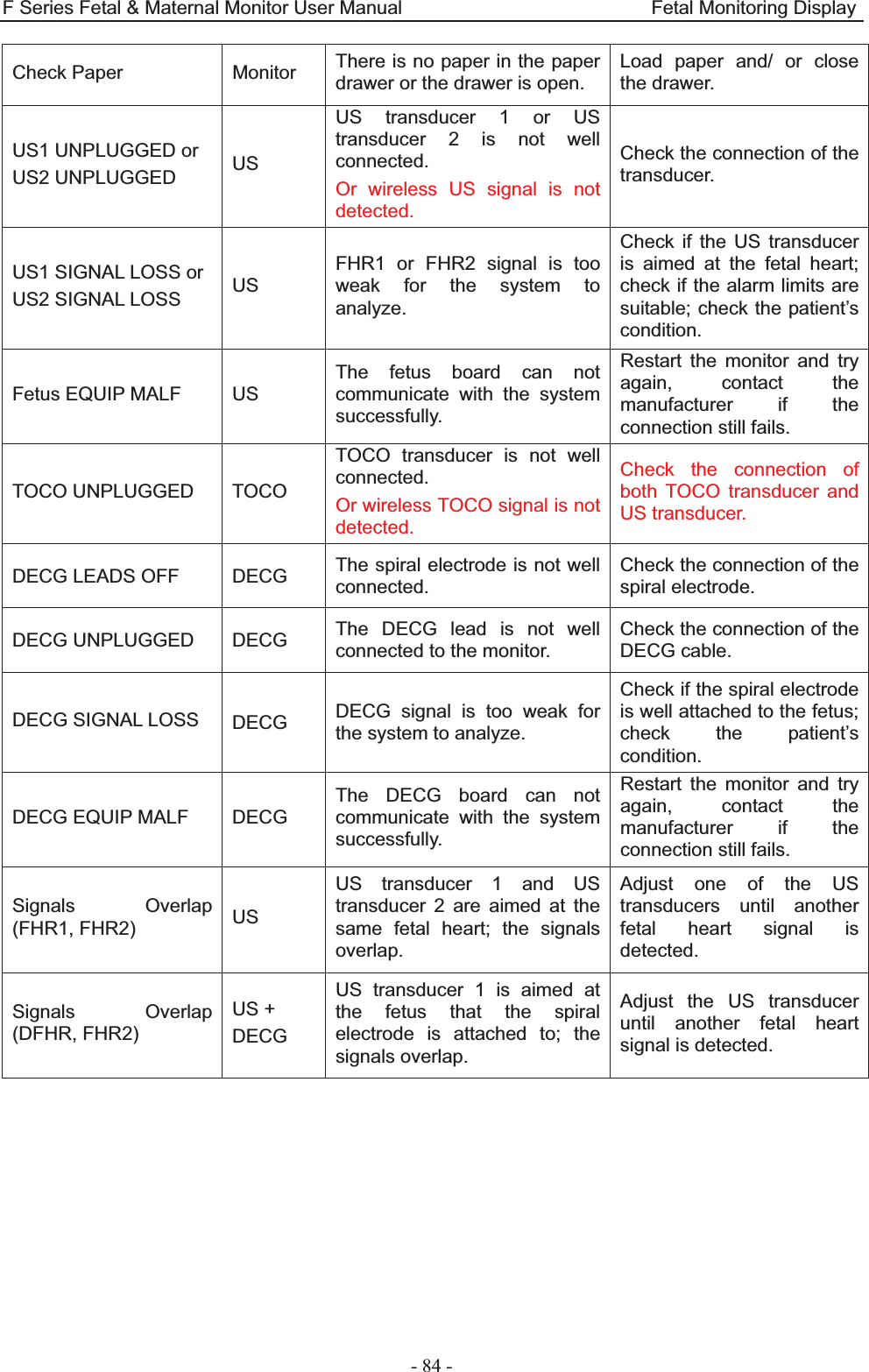
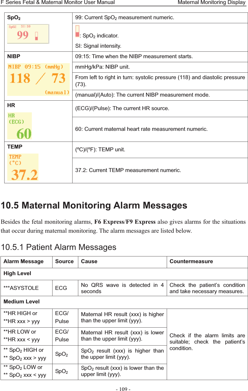
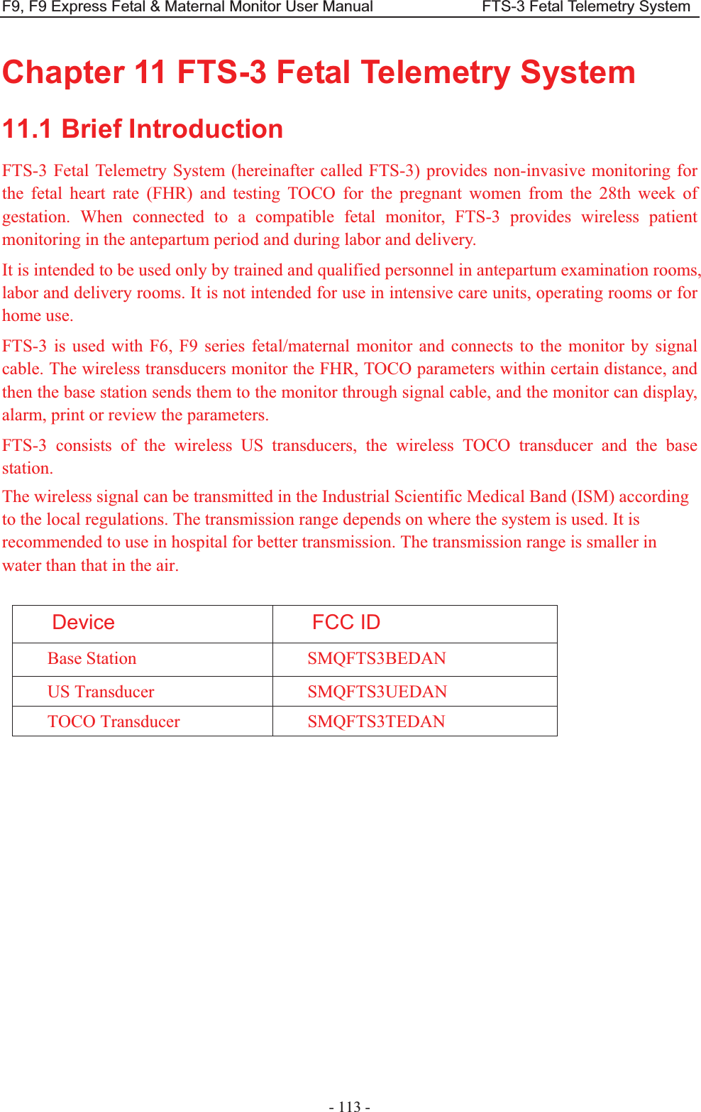
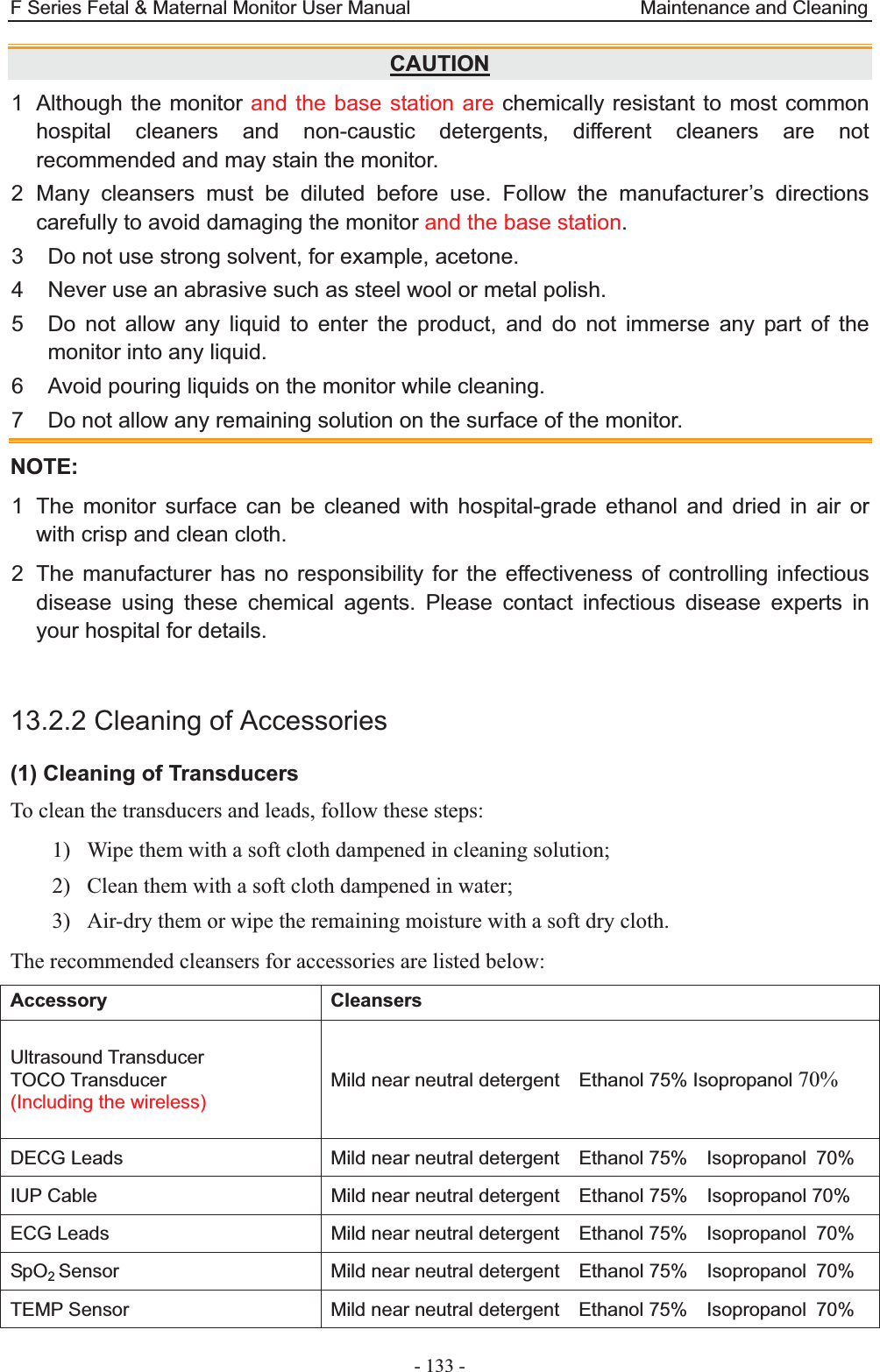
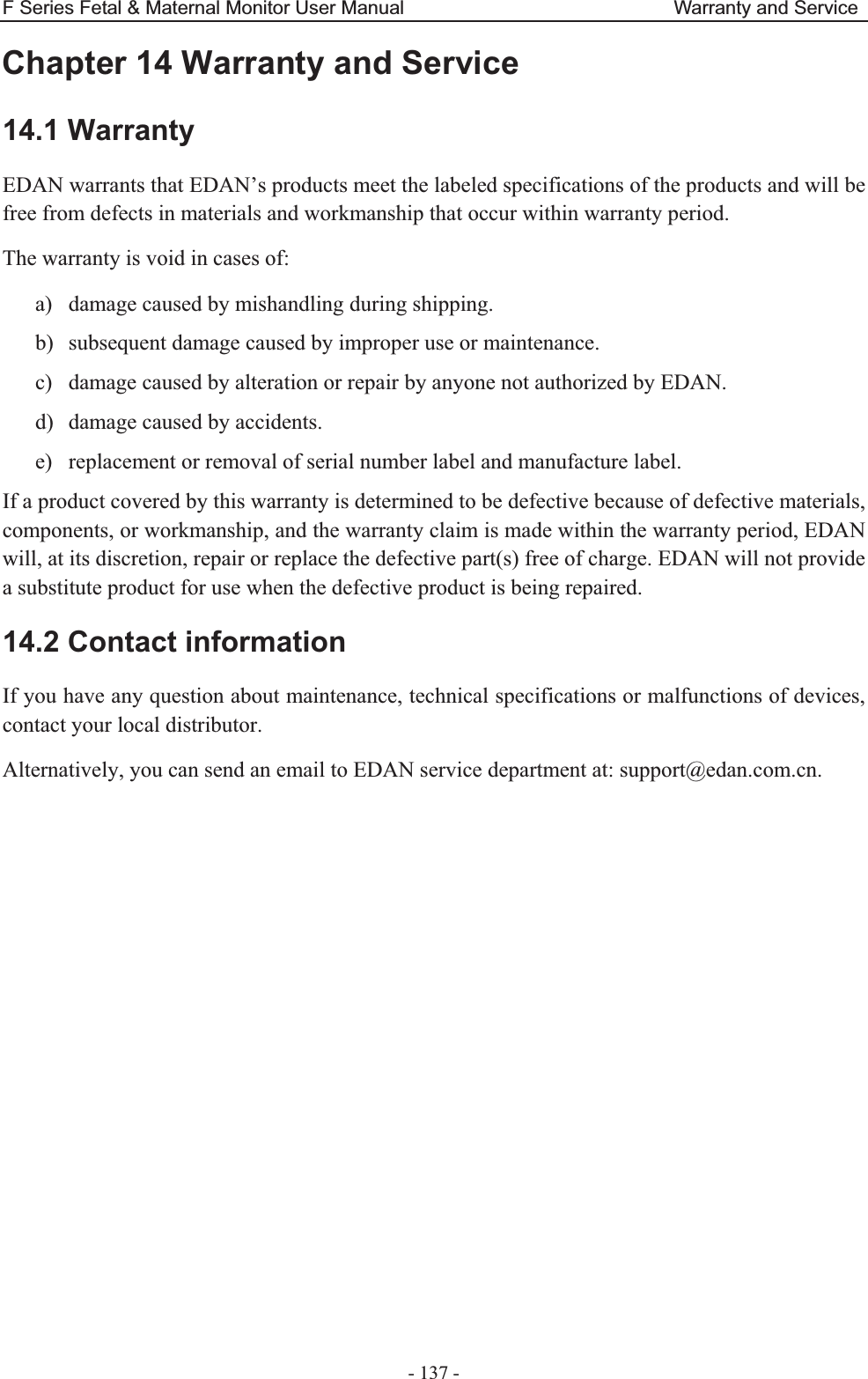
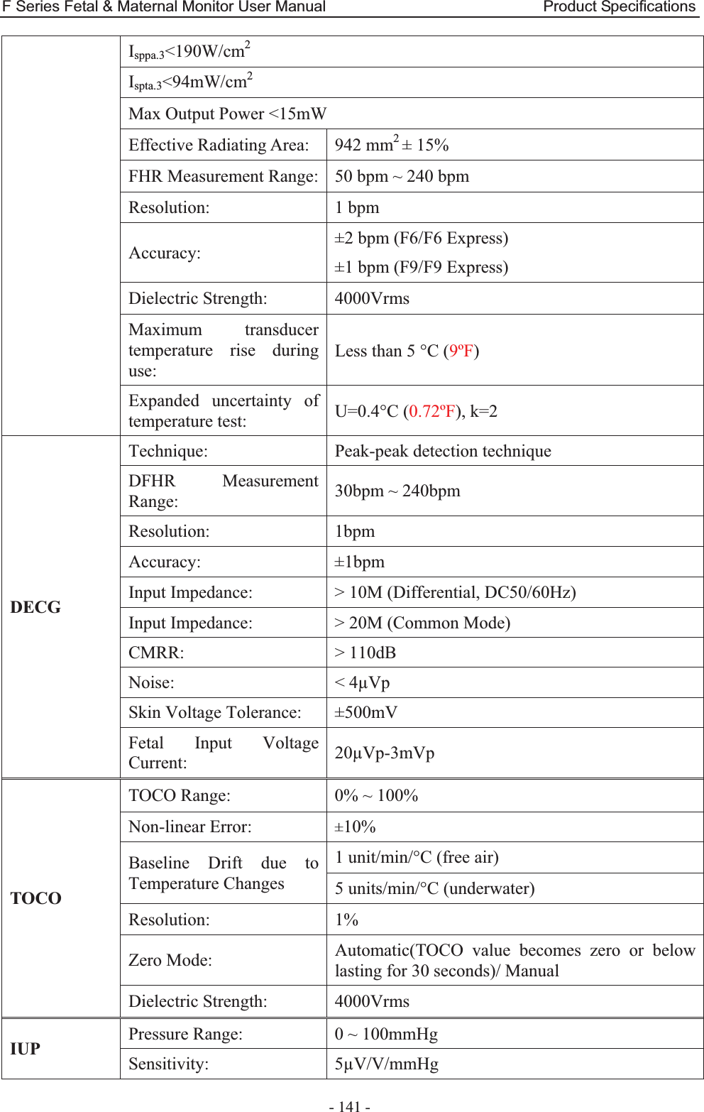
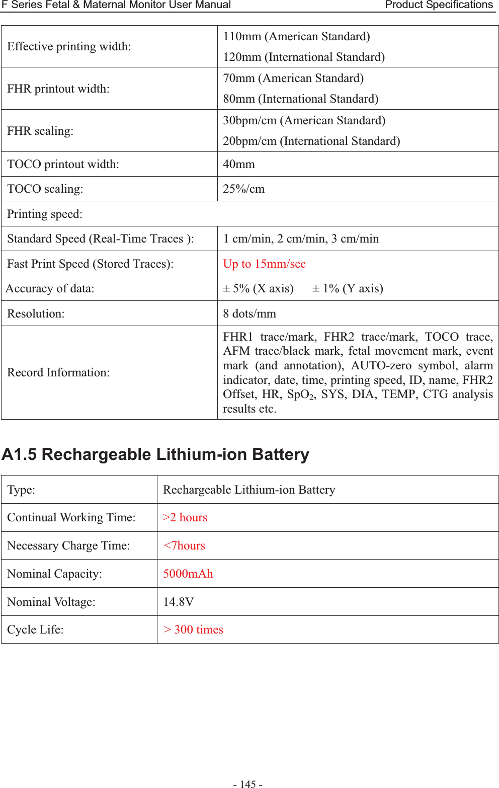
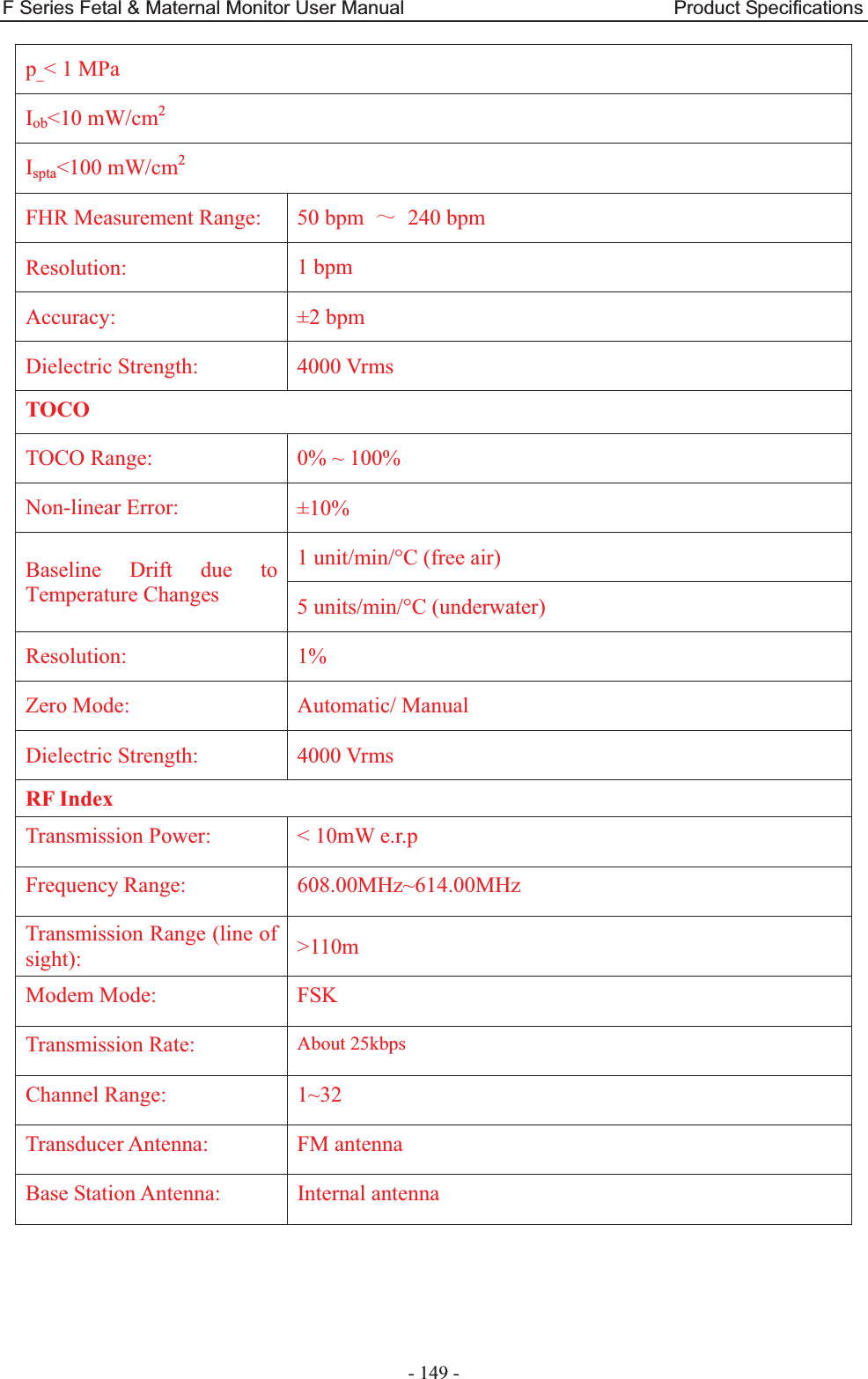
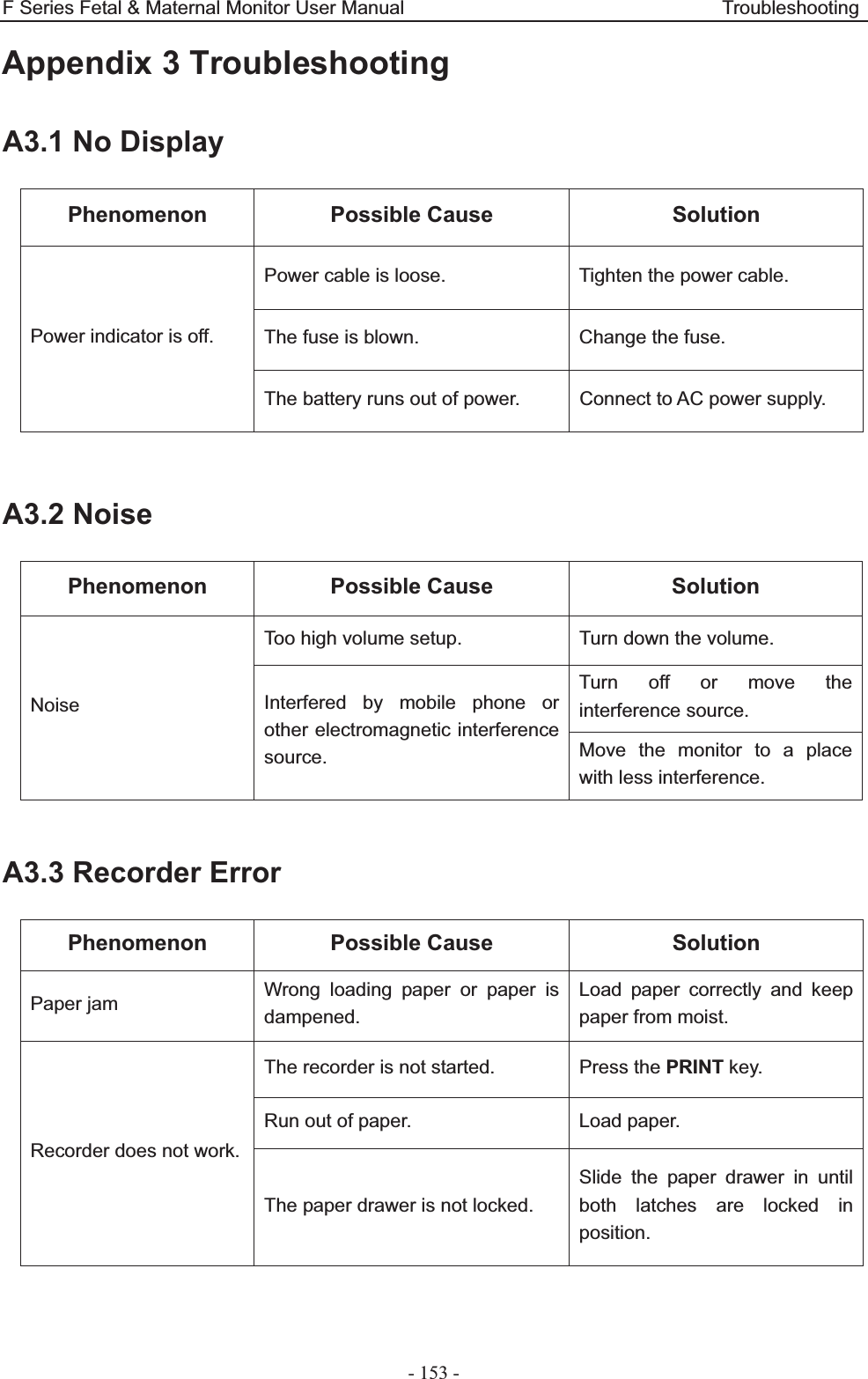
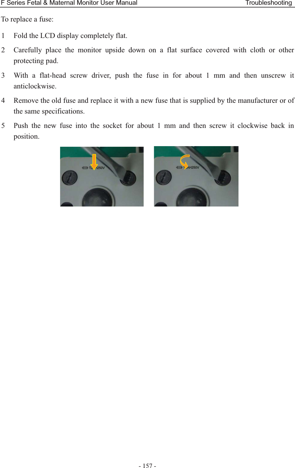
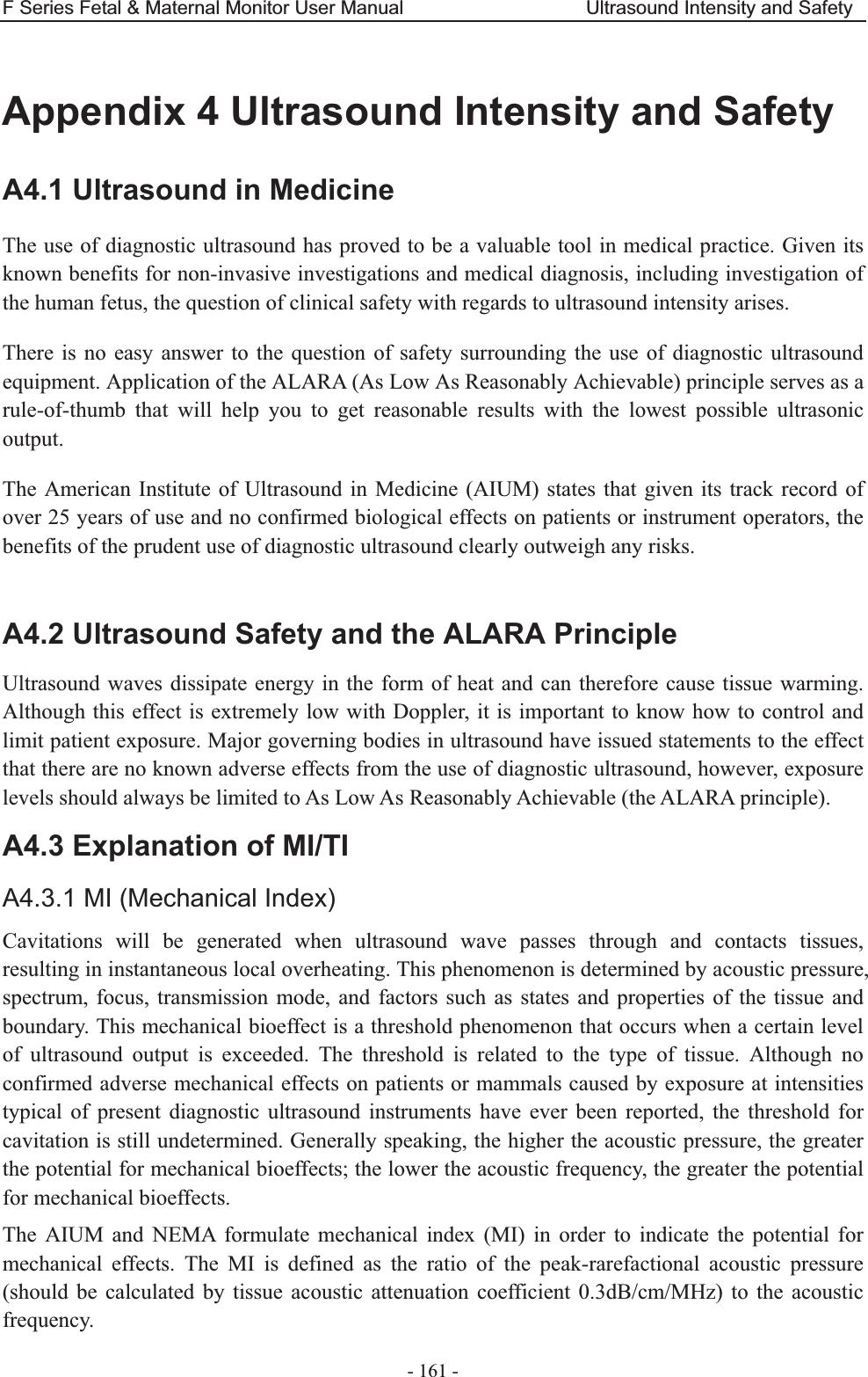
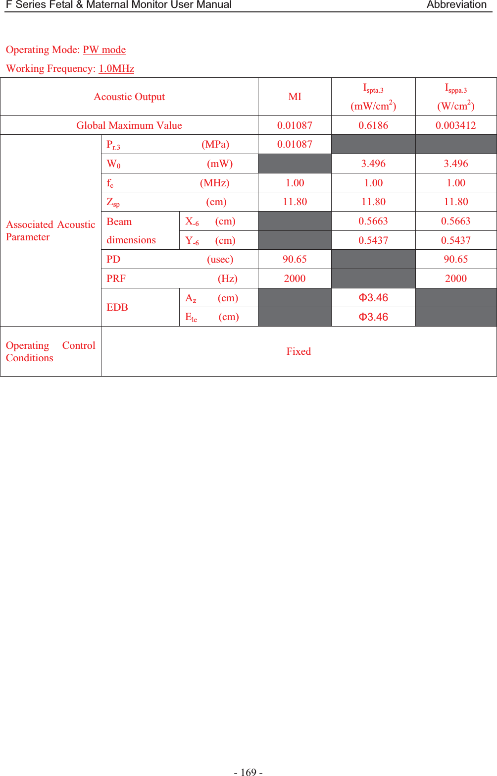
![F Series Fetal & Maternal Monitor User Manual Abbreviation - 168 - A4.6.2 Test of Wireless Probe (FTS-3) Acoustic Output Reporting Table Operating Mode: PW mode Working Frequency: 1.0MHz Index Label MI TIS TIB TIC Scan Non-scan Non-scan Aaprt1 Aaprt>1 Global Maximum Index Value 0.01087 0.002949 0.01939 N/A Associated Acoustic Parameters Pr.a (MPa) 0.01087 P (mW) 3.496 N/A Min of [Pa(Zs),Ita.a(Zs)] (mW) 0.62 Zs (cm) 12.50 Zbp (cm) 5.188 Zb (cm) 11.95 Z at max Ipi.a (cm) 12.10 12.10 deq(Zb) (cm) 1.77 fawf (MHz) 1.00 1.00 1.00 N/A Dim of Aaprt X (cm) ĭ3.46 ĭ3.46 N/A Y (cm) ĭ3.46 ĭ3.46 N/A Other Information td (usec) 90.65 prr (Hz) 2000 Pr at max Ipi (MPa) 0.01743 Deq at max Ipi (cm) 1.74 Ipi.3 at max MI (W/cm2) 0.003412 Focal Length Flx (cm) N/A Fly (cm) N/A Operating Control Conditions Focus(mm) Fixed Depth(mm) Fixed Freq(MHz) 1.0](https://usermanual.wiki/EDAN-INSTRUMENTS/FTS3UEDAN/User-Guide-2533650-Page-179.png)
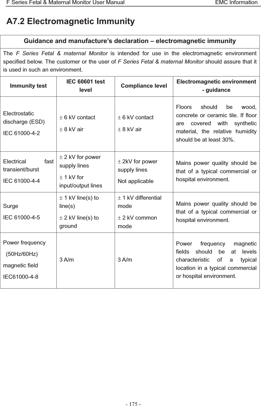
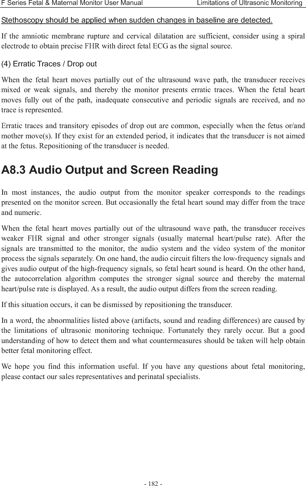
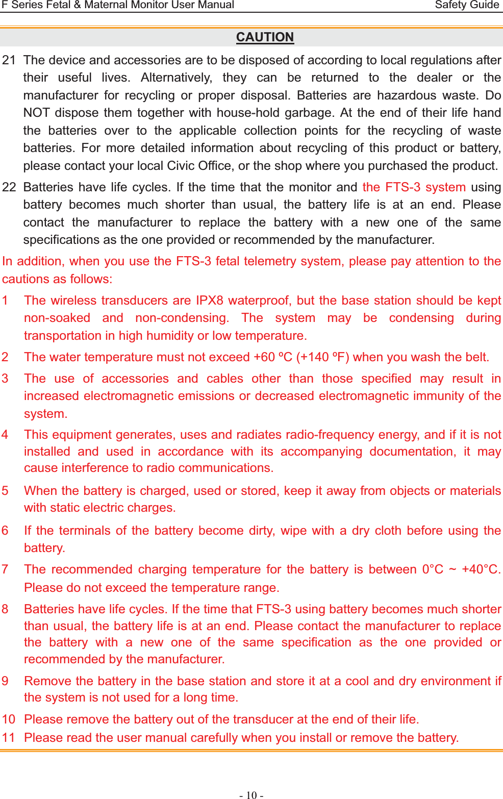
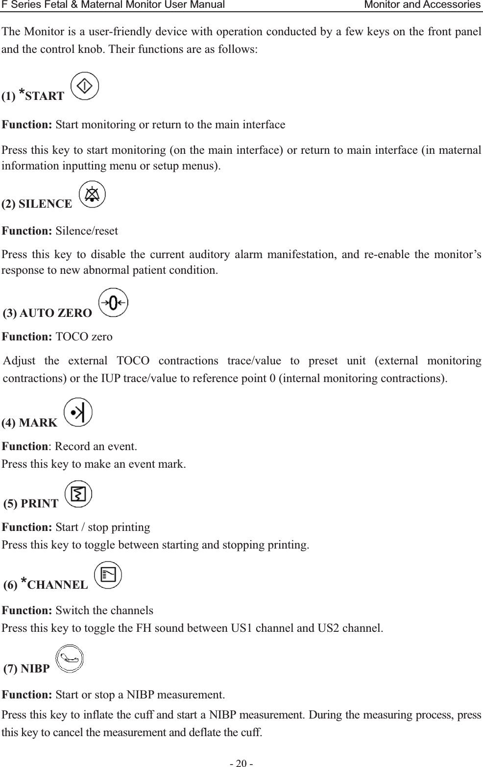
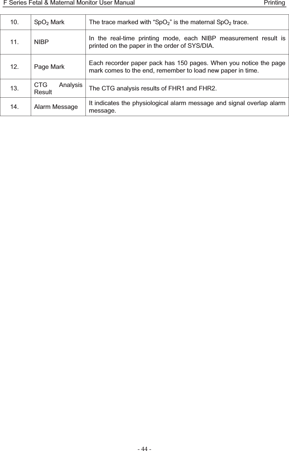
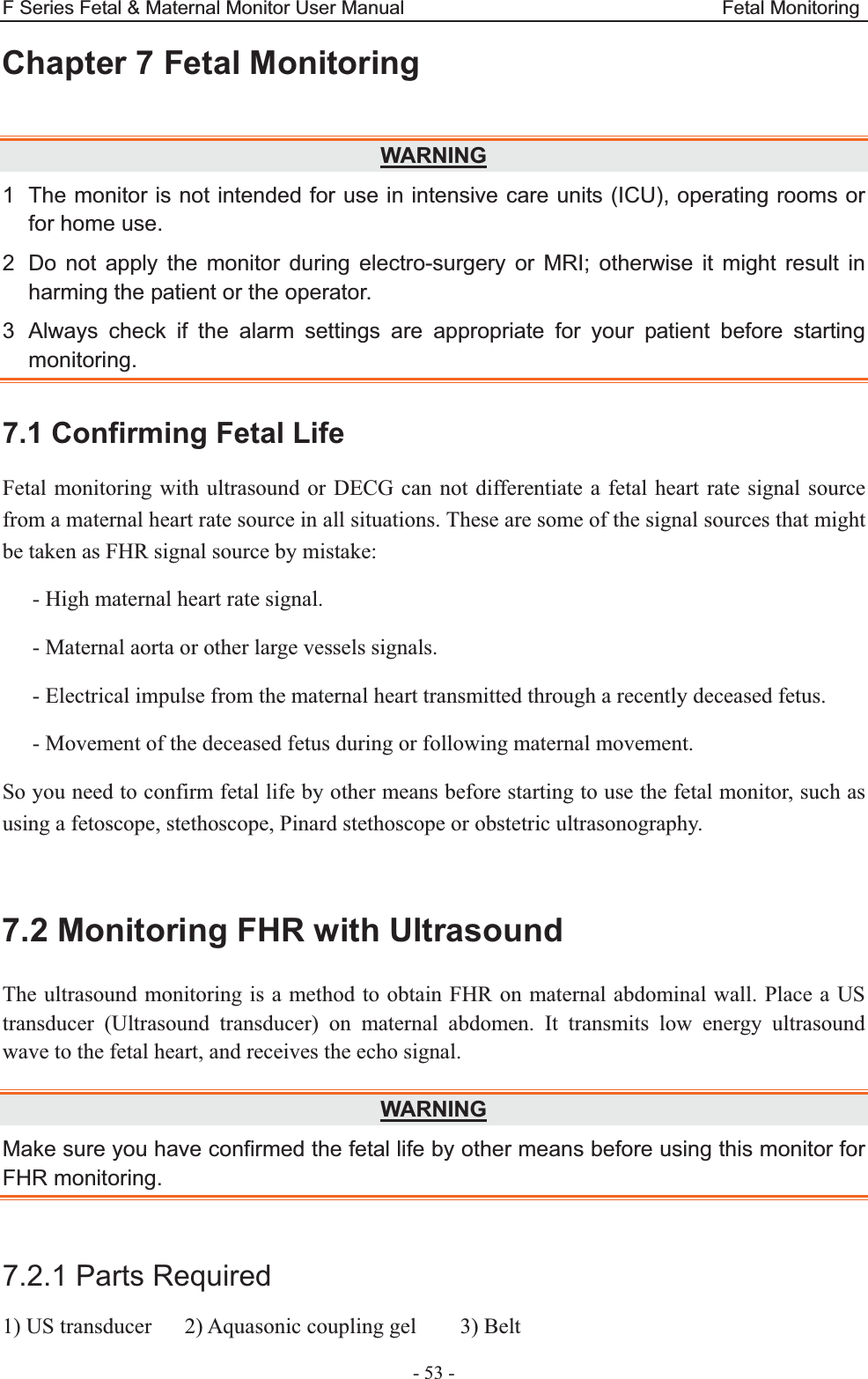
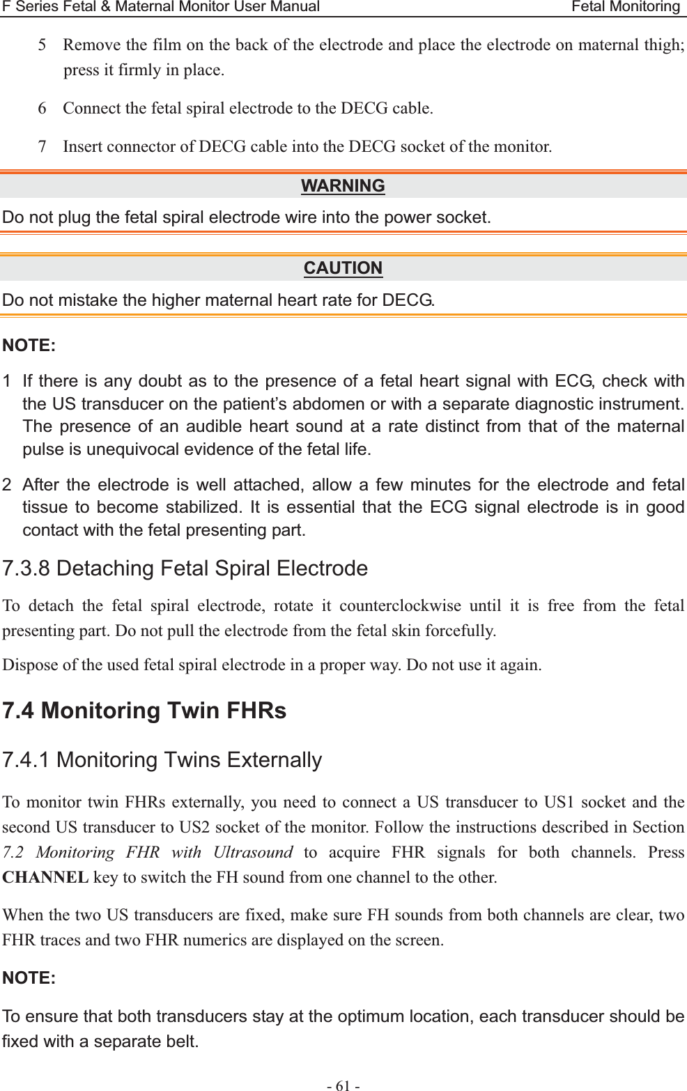
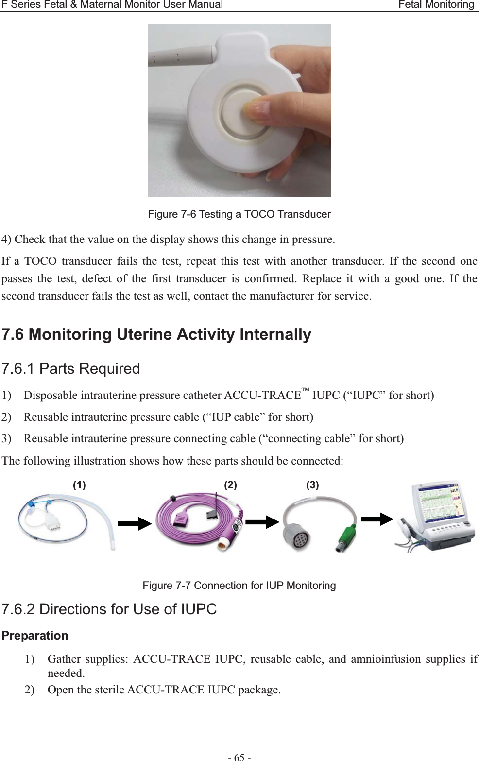
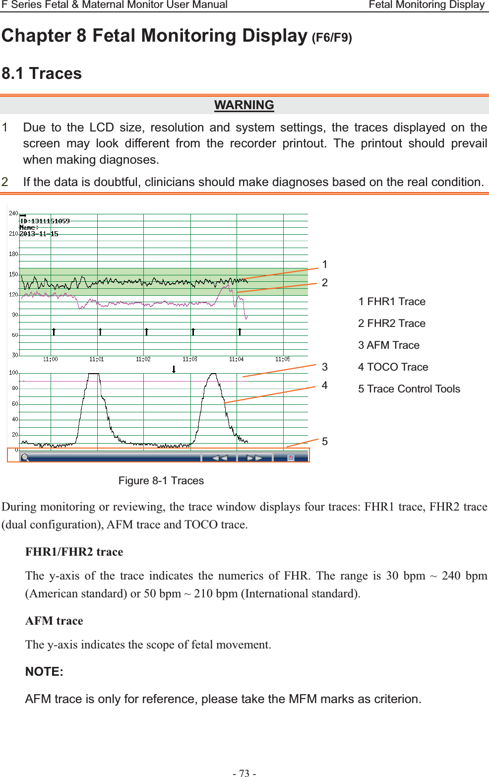
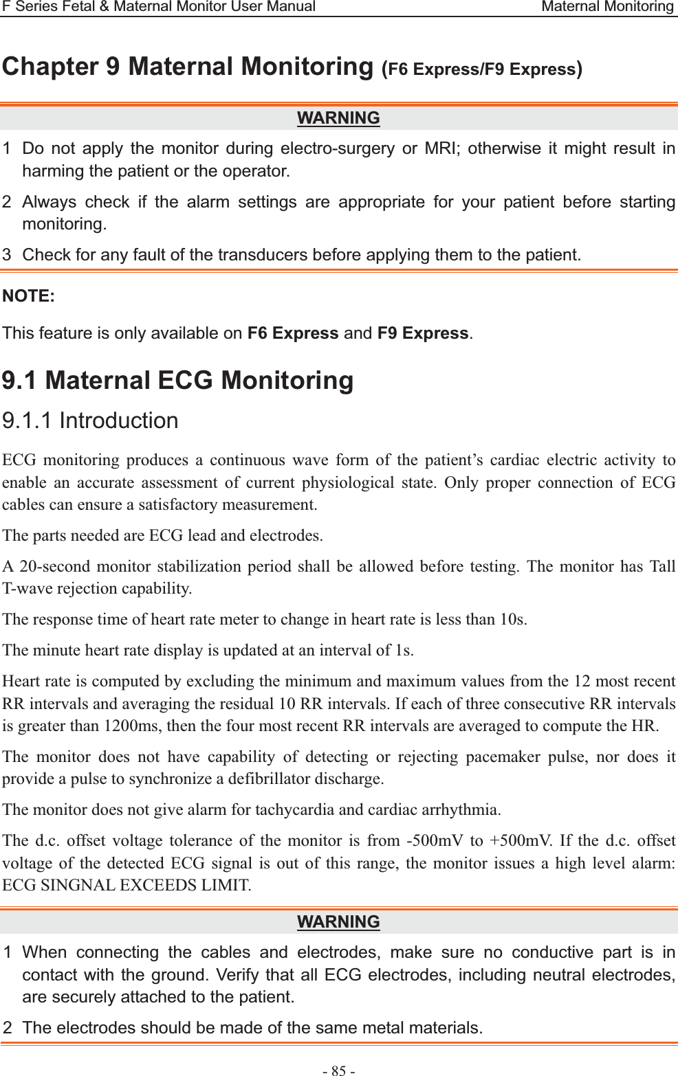
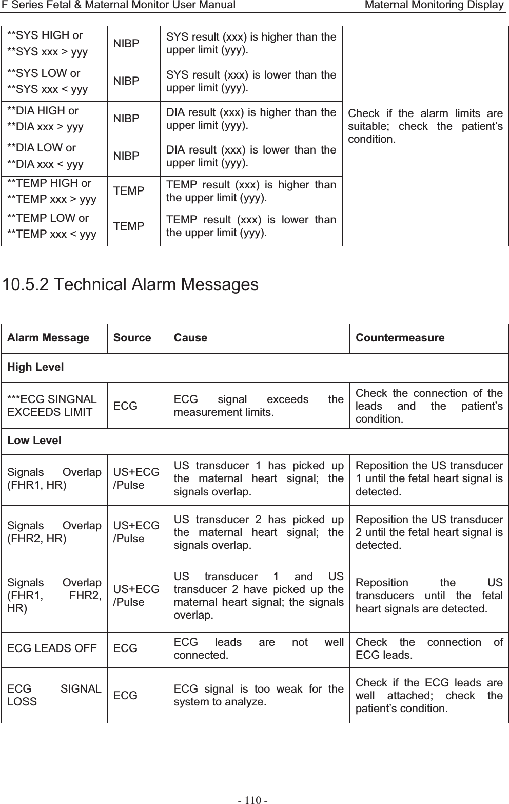
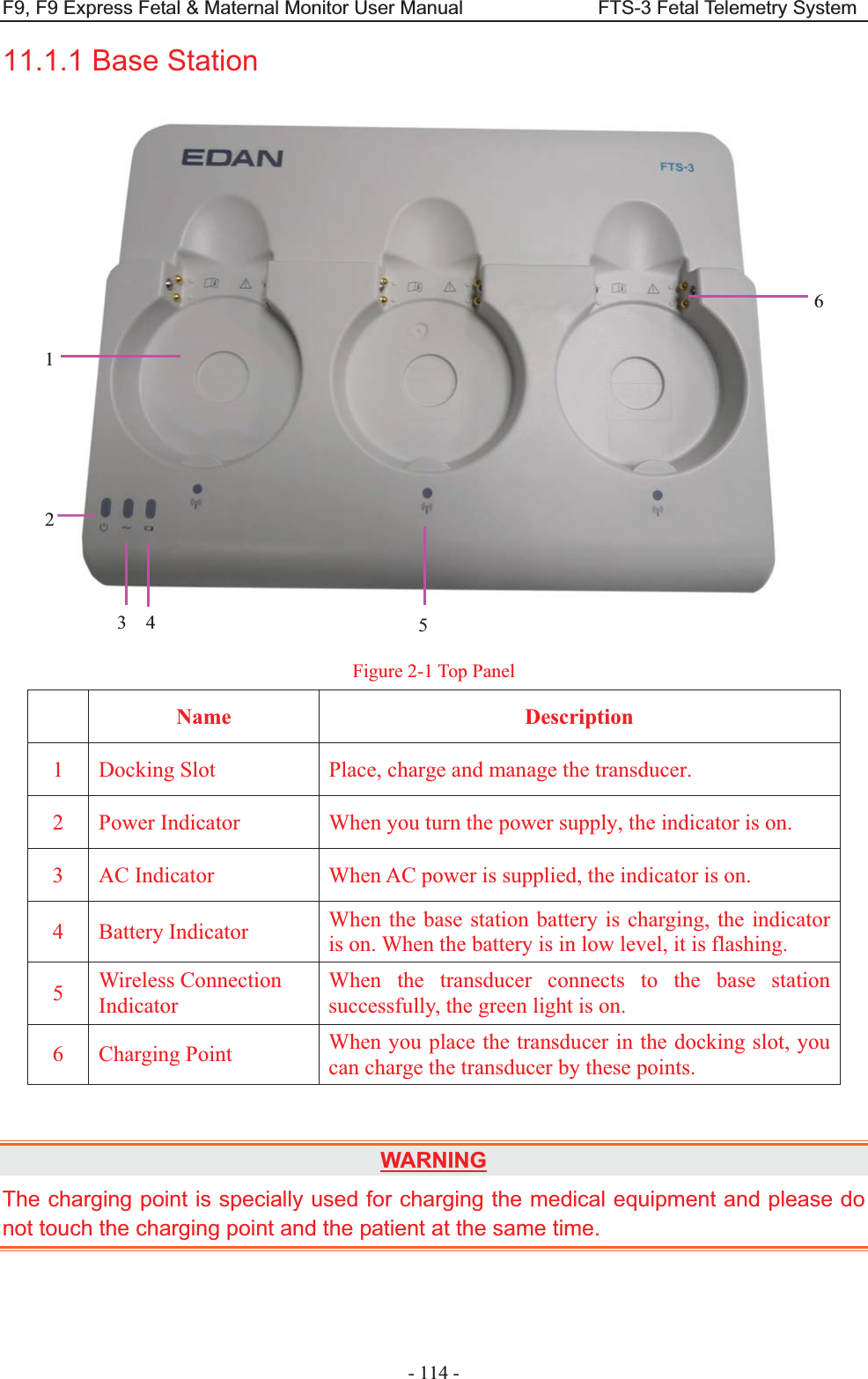
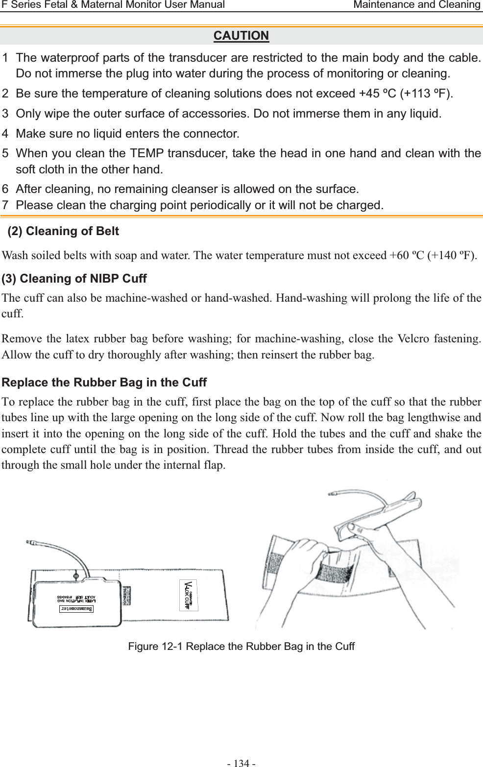
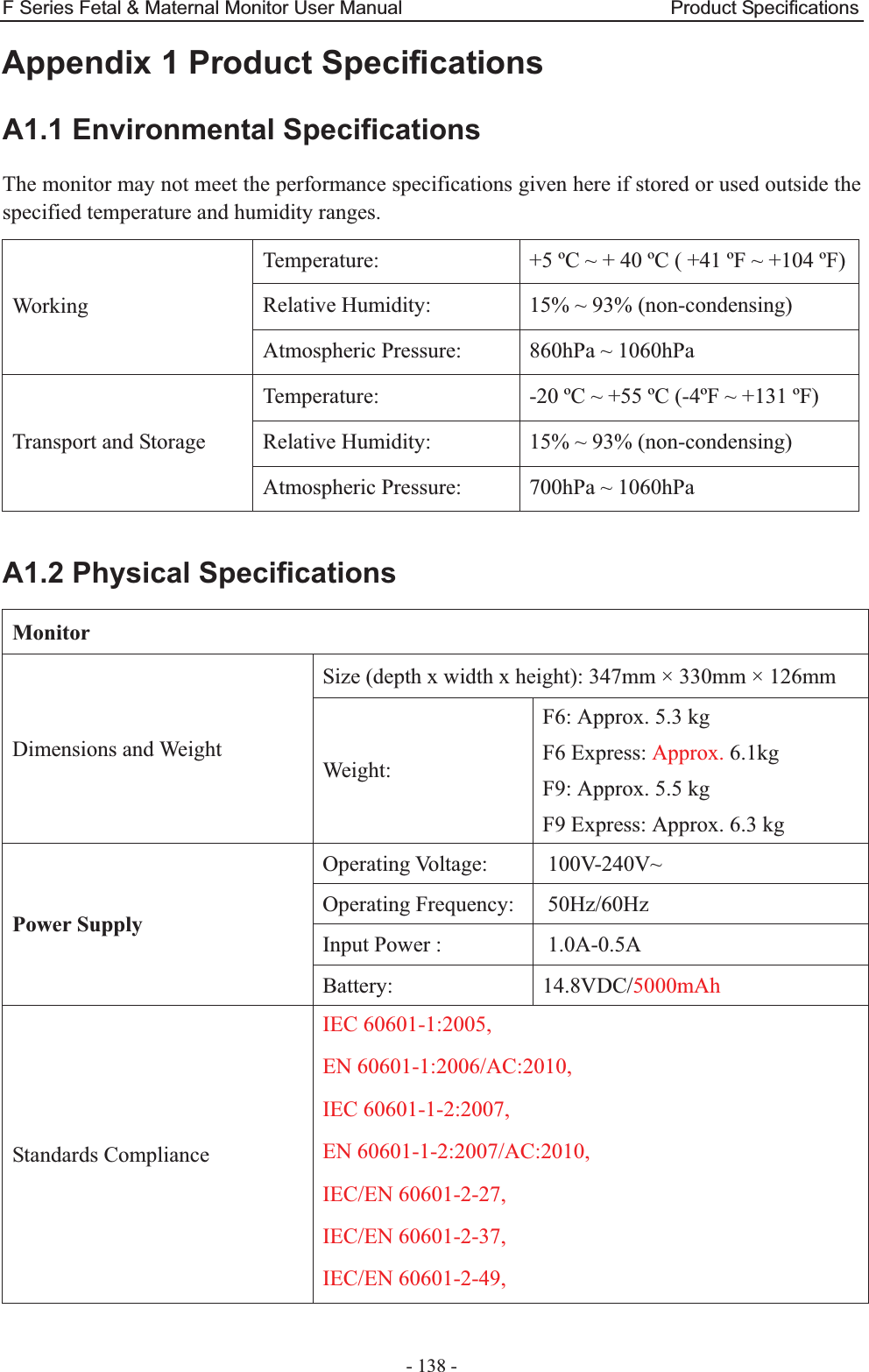
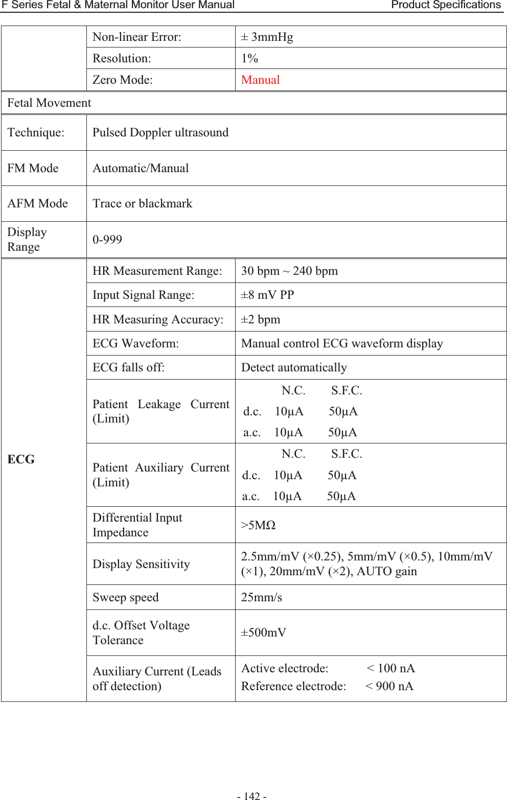
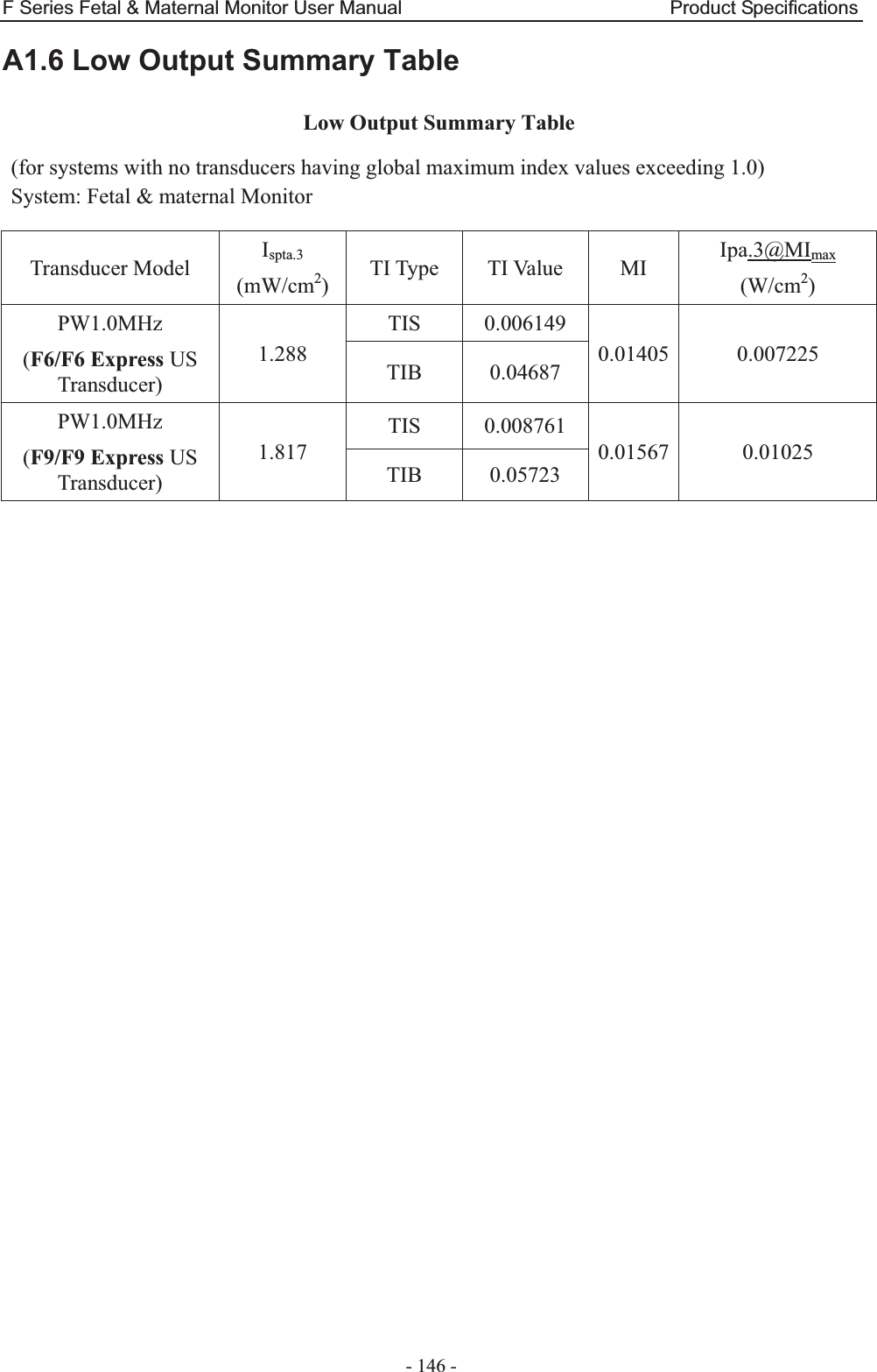
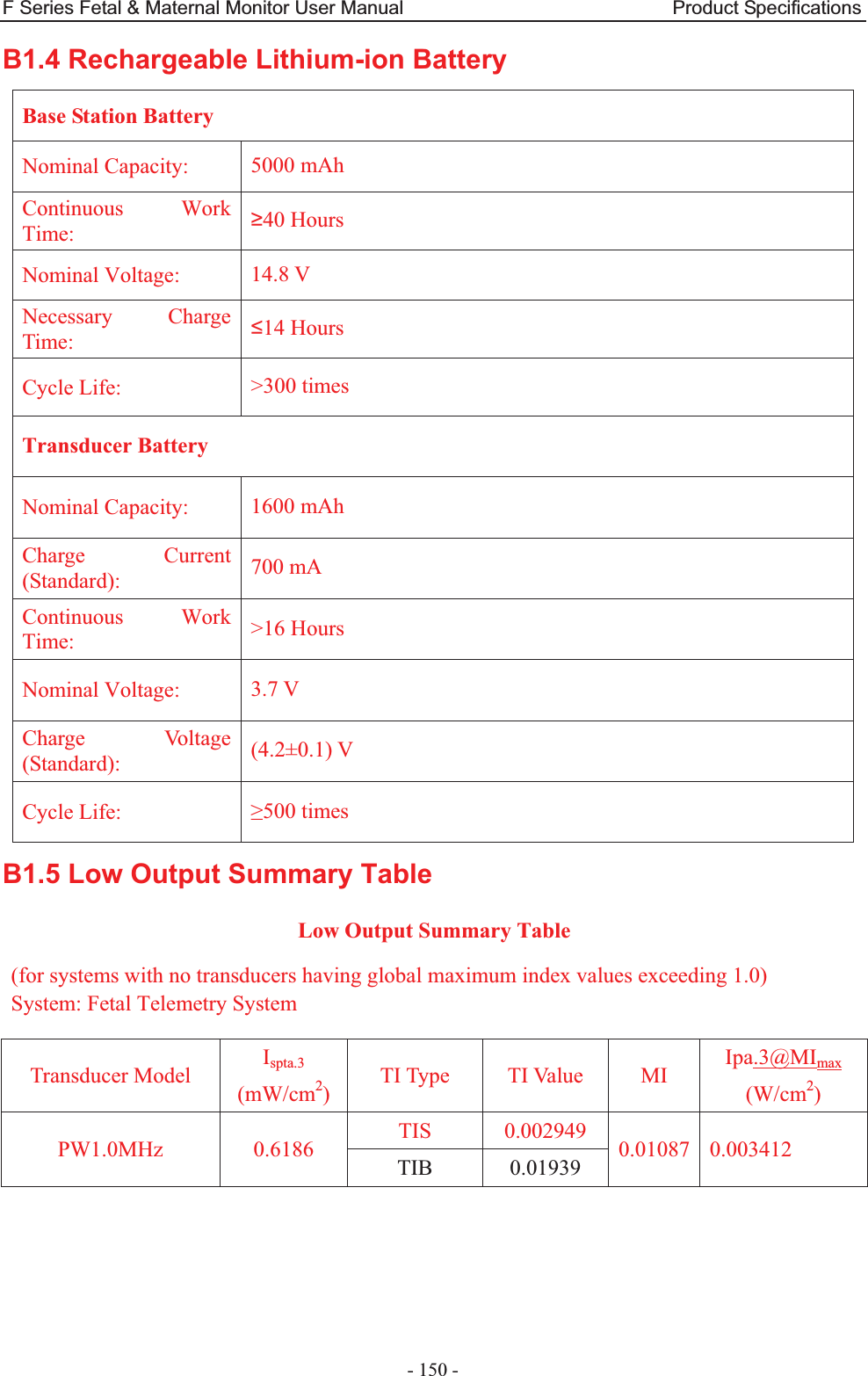
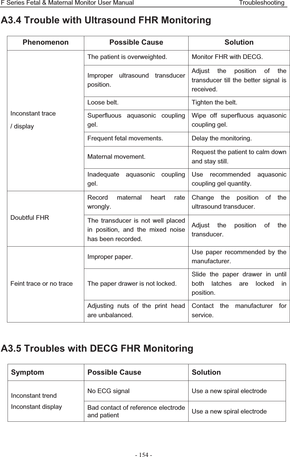
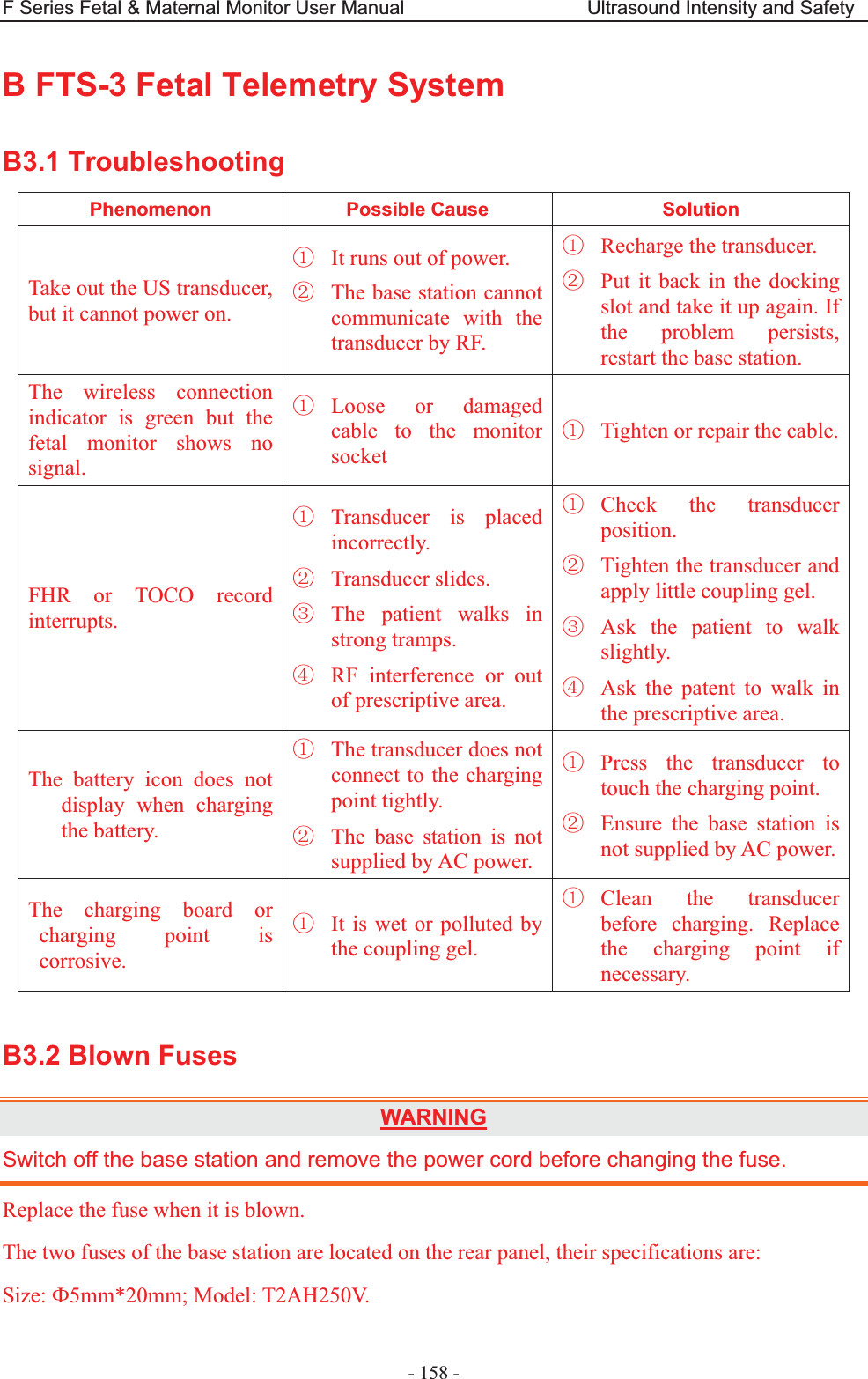
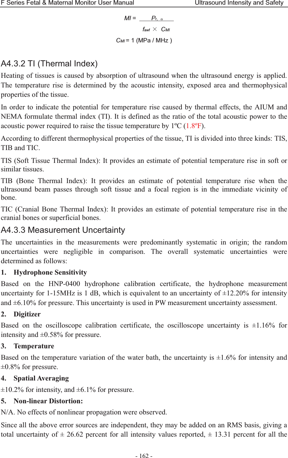
![F Series Fetal & Maternal Monitor User Manual Abbreviation - 170 - Appendix 5 Abbreviation The abbreviations used in this manual and their full names are listed below: Abbreviation Full Name AC Alternative Current AFM Automatic Fetal Movement [Detection] BPM Beat(s) Per Minute CTG Cardiotocography DC Direct Current DECG Direct ECG DFHR Direct FHR DIA Diastolic Blood Pressure ECG Electrocardiogram FH Fetal Heart FHR Fetal Heart Rate FM Fetal Movement FS Fetal Stimulator HR Heart Rate ICU Intensive Care Unit ID Identity IUP Intra-Uterine Pressure IUPC Intra-Uterine Pressure Catheter LCD Liquid Crystal Display MAP Mean Artery Blood Pressure MECG Maternal ECG MFM Manual Fetal Movement [Detection] MRI Magnetic Resonance Imaging NIBP Non-Invasive Blood Pressure NST Non Stress Test PR Pulse Rate SOV Signals Overlap Verification SpO2 Pulse Oximetry](https://usermanual.wiki/EDAN-INSTRUMENTS/FTS3UEDAN/User-Guide-2533650-Page-181.png)
![F Series Fetal & Maternal Monitor User Manual Abbreviation - 171 - STV Short-Term Variation SYS Systolic Blood PressureTEMP Temperature TOCO Tocotonometer UA Uterine Activity [TOCO] US Ultrasound [Transducer]](https://usermanual.wiki/EDAN-INSTRUMENTS/FTS3UEDAN/User-Guide-2533650-Page-182.png)