EDAN INSTRUMENTS FTS3UEDAN Fetal Telemetry System User Manual Rev 5
EDAN INSTRUMENTS, INC. Fetal Telemetry System Rev 5
User Manual Rev.5

I
About this Manual
P/N: 01.54.455327
MPN: 01.54.455327017
Release Date: Jan. 2015
© Copyright EDAN INSTRUMENTS, INC. 2008 - 2015. All rights reserved.
Statement
This manual will help you understand the operation and maintenance of the product better. It is
reminded that the product shall be used strictly complying with this manual. User’s operation
failing to comply with this manual may result in malfunction or accident for which EDAN
INSTRUMENTS, INC. (hereinafter called EDAN) can not be held liable.
EDAN owns the copyrights of this manual. Without prior written consent of EDAN, any
materials contained in this manual shall not be photocopied, reproduced or translated into other
languages.
Materials protected by the copyright law, including but not limited to confidential information
such as technical information and patent information are contained in this manual, the user shall
not disclose such information to any irrelevant third party.
The user shall understand that nothing in this manual grants him, expressly or implicitly, any
right or license to use any of the intellectual properties of EDAN.
EDAN holds the rights to modify, update, and ultimately explain this manual.
Product Information
Product Name: Fetal & Maternal Monitor
Model: F6, F6 Express, F9, F9 Express
Responsibility of the Manufacturer
EDAN only considers itself responsible for any effect on safety, reliability and performance of
the equipment if:
Assembly operations, extensions, re-adjustments, modifications or repairs are carried out by
persons authorized by EDAN, and
The electrical installation of the relevant room complies with national standards, and
The instrument is used in accordance with the instructions for use.
Upon request, EDAN may provide, with compensation, necessary circuit diagrams, and other
II
information to help qualified technician to maintain and repair some parts, which EDAN may
define as user serviceable.
Terms Used in this Manual
This guide is designed to give key concepts on safety precautions.
WARNING
A WARNING label advises against certain actions or situations that could result in personal
injury or death.
CAUTION
A CAUTION label advises against actions or situations that could damage equipment, produce
inaccurate data, or invalidate a procedure.
NOTE
A NOTE provides useful information regarding a function or a procedure.
III
Table of Contents
Chapter 1 Safety Guide ················································································································ 1
1.1 Intended Use....................................................................................................................... 1
1.2 Features .............................................................................................................................. 2
1.3 Instruction for Safe Operation ............................................................................................ 2
1.4 Ultrasound Safety Guide .................................................................................................... 3
1.5 Safety Precautions .............................................................................................................. 4
1.6 Definitions and Symbols .................................................................................................. 11
Chapter 2 Installation Guide ······································································································ 15
2.1 Opening and Checking Package ....................................................................................... 15
2.2 Installing Battery .............................................................................................................. 15
2.3 Installing Monitor ............................................................................................................ 16
2.4 Connecting Power Cable .................................................................................................. 17
Chapter 3 Monitor and Accessories ··························································································· 18
3.1 Overview .......................................................................................................................... 18
3.1.1 Keys and Control Knob .......................................................................................... 19
3.1.2 Indicators ................................................................................................................ 21
3.2 Accessories ....................................................................................................................... 22
3.2.1 Ultrasound (US) Transducers ................................................................................. 22
3.2.2 TOCO Transducers ................................................................................................ 22
3.2.3 Belt ......................................................................................................................... 23
3.2.4 Remote Event Marker ............................................................................................ 23
3.2.5 DECG Cable........................................................................................................... 23
3.2.6 Fetal Spiral Electrode ............................................................................................. 24
3.2.7 IUP Cable ............................................................................................................... 24
3.2.8 IUP Catheter ........................................................................................................... 25
3.2.9 ECG Cable ............................................................................................................. 25
3.2.10 SpO2 Sensor ......................................................................................................... 25
3.2.11 NIBP Cuff ............................................................................................................ 26
3.2.12 TEMP Sensor ....................................................................................................... 26
3.3 Screen ............................................................................................................................... 27
3.3.1 Main Interface ........................................................................................................ 27
3.3.2 Setup Interface ....................................................................................................... 30
3.3.3 Touch Screen .......................................................................................................... 31
Chapter 4 Alarms ························································································································ 33
IV
4.1 Alarms Classification ....................................................................................................... 33
4.2 Audible Alarm .................................................................................................................. 33
4.3 Visual Alarm .................................................................................................................... 34
4.4 Choosing the Alarm Display Form .................................................................................. 35
4.5 Changing the Alarm Volume ........................................................................................... 35
4.6 *Choosing Alarm Silence Duration ................................................................................. 35
4.7 Choosing Signal Loss Delay ............................................................................................ 35
4.8 Pausing or Resetting the Alarm ........................................................................................ 36
4.9 *Reviewing Alarms .......................................................................................................... 36
4.10 Alarm Treatment Measures ............................................................................................ 37
4.11 Testing Alarms ............................................................................................................... 38
4.12 Patient Alarm Defaults ................................................................................................... 38
Chapter 5 Printing ······················································································································ 40
5.1 *Function Description ...................................................................................................... 40
5.2 Printing Configuration ..................................................................................................... 41
5.2.1 Switching Auto Start Printing On or Off ............................................................... 41
5.2.2 *Choosing the Paper Speed .................................................................................... 41
5.2.3 *Changing the Print Timer ..................................................................................... 41
5.2.4 Switching Print Self-Check On or Off ................................................................... 42
5.2.5 Changing Printing End Volume ............................................................................. 42
5.3 Understanding the Recorder Paper Printout ..................................................................... 42
Chapter 6 Pre-Monitoring Preparation ···················································································· 45
6.1 Loading Recorder paper ................................................................................................... 45
6.2 Switching On .................................................................................................................... 47
6.3 Checking Recorder Paper ................................................................................................. 47
6.4 Adjusting Screen Angle ................................................................................................... 48
6.5 Setting Date and Time ...................................................................................................... 49
6.6 Connecting Transducers ................................................................................................... 49
6.7 Placing Accessories in the Holder.................................................................................... 50
6.8 Adjusting the Volume ...................................................................................................... 51
Chapter 7 Fetal Monitoring ······································································································· 53
7.1 Confirming Fetal Life ...................................................................................................... 53
7.2 Monitoring FHR with Ultrasound .................................................................................... 53
7.2.1 Parts Required ........................................................................................................ 53
7.2.2 FHR Monitoring Procedure.................................................................................... 54
7.2.3 Switching FHR Alarm On or Off ........................................................................... 55
V
7.2.4 Changing FHR Alarm Limits ................................................................................. 56
7.2.5 Changing FHR Alarm Delay .................................................................................. 56
7.2.6 Testing US Transducers ......................................................................................... 57
7.3 Monitoring FHR with DECG ........................................................................................... 58
7.3.1 Contraindications ................................................................................................... 58
7.3.2 Parts Required ........................................................................................................ 58
7.3.3 Preparing Patient's Skin Prior to Placing Electrodes ............................................. 58
7.3.4 Changing DECG Beep Volume ............................................................................. 59
7.3.5 Switching the Artifact Suppression On or Off ....................................................... 59
7.3.6 Directions for Using Fetal Spiral Electrode ........................................................... 60
7.3.7 DECG Monitoring Procedure ................................................................................ 60
7.3.8 Detaching Fetal Spiral Electrode ........................................................................... 61
7.4 Monitoring Twin FHRs .................................................................................................... 61
7.4.1 Monitoring Twins Externally ................................................................................. 61
7.4.2 Monitoring Internally ............................................................................................. 62
7.4.3 Signals Overlap Verification (SOV) ...................................................................... 62
7.4.4 Changing FHR2 Offset .......................................................................................... 62
7.5 Monitoring Uterine Activity Externally ........................................................................... 63
7.5.1 Parts Required ........................................................................................................ 63
7.5.2 TOCO Monitoring Procedure ................................................................................ 63
7.5.3 Changing UA Baseline ........................................................................................... 64
7.5.4 Testing TOCO Transducers ................................................................................... 64
7.6 Monitoring Uterine Activity Internally ............................................................................ 65
7.6.1 Parts Required ........................................................................................................ 65
7.6.2 Directions for Use of IUPC .................................................................................... 65
7.6.3 IUP Monitoring Procedure ..................................................................................... 68
7.6.4 Checking Intrauterine Pressure Cable Function ..................................................... 68
7.7 Monitoring Fetal Movement ............................................................................................ 69
7.7.1 Auto Fetal Movement (AFM) Monitoring ............................................................. 69
7.7.2 Enabling or Disabling AFM Trace ......................................................................... 69
7.7.3 Changing AFM Gain .............................................................................................. 69
7.7.4 Choosing AFM Mode ............................................................................................ 70
7.7.5 Choosing FM Source ............................................................................................. 70
7.7.6 Manual Fetal Movement (MFM) Monitoring ........................................................ 70
7.7.7 Changing MFM Volume ........................................................................................ 70
7.8 *Start Monitoring ............................................................................................................. 71
VI
7.9 *Inputting Maternal Information (Mat. Info) ................................................................... 71
7.9.1 Auto ID................................................................................................................... 71
7.9.2 Changing Maternal Information ............................................................................. 71
7.9.3 Switching Mat. Info Inputting On or Off ............................................................... 72
Chapter 8 Fetal Monitoring Display (F6/F9) ············································································ 73
8.1 Traces ............................................................................................................................... 73
8.1.1 Changing Time Scale ............................................................................................. 74
8.2 Trace Control Tools ......................................................................................................... 75
8.2.1 Data Saving ............................................................................................................ 75
8.2.2 *Searching for a File .............................................................................................. 75
8.2.3 *Reviewing ............................................................................................................ 76
8.2.4 *CTG Analysis ....................................................................................................... 77
8.2.5 *Marking a Note .................................................................................................... 80
8.3 Numerics .......................................................................................................................... 81
8.3.1 Changing Numeric Window Position (F9) ............................................................ 83
8.4 Fetal Monitoring Alarm Messages ................................................................................... 83
8.4.1 Patient Alarm Messages ......................................................................................... 83
8.4.2 Technical Alarm Messages .................................................................................... 83
Chapter 9 Maternal Monitoring (F6 Express/F9 Express) ····················································· 85
9.1 Maternal ECG Monitoring ............................................................................................... 85
9.1.1 Introduction ............................................................................................................ 85
9.1.2 How to Place 3-lead ECG Cables .......................................................................... 86
9.1.3 ECG Monitoring Procedure ................................................................................... 87
9.1.4 Changing ECG Source ........................................................................................... 87
9.1.5 Changing ECG Gain .............................................................................................. 88
9.1.6 Enabling ECG Calibration ..................................................................................... 88
9.2 Maternal SpO2 Monitoring ............................................................................................... 89
9.2.1 Introduction ............................................................................................................ 89
9.2.2 SpO2 Monitoring Procedure ................................................................................... 91
9.2.3 Enabling SpO2 Trace Printing ................................................................................ 92
9.2.4 Assessing the Validity of a SpO2 Reading ............................................................ 92
9.2.5 SI (Signal Intensity)* ............................................................................................. 93
9.2.6 Switching the SpO2 Alarm On or Off .................................................................... 93
9.2.7 Changing SpO2 Alarm Limits ................................................................................ 93
9.3 Maternal HR Monitoring.................................................................................................. 94
9.3.1 Introduction ............................................................................................................ 94
VII
9.3.2 Choosing HR Source .............................................................................................. 94
9.3.3 Changing HR Beep Volume ................................................................................... 94
9.3.4 Enabling HR Trace ................................................................................................. 95
9.3.5 Switching the HR Alarm On or Off ....................................................................... 95
9.3.6 Changing HR Alarm Limits ................................................................................... 95
9.3.7 Signals Overlap Verification .................................................................................. 95
9.4 Maternal NIBP Monitoring .............................................................................................. 96
9.4.1 Introduction ............................................................................................................ 96
9.4.2 How to Apply NIBP Cuff ...................................................................................... 97
9.4.3 Preparation for NIBP Monitoring .......................................................................... 98
9.4.4 *Auto Measurement ............................................................................................... 99
9.4.5 *Manual Measurement ......................................................................................... 100
9.4.6 Correcting the Measurement ................................................................................ 101
9.4.7 Changing NIBP Unit ............................................................................................ 101
9.4.8 Switching the NIBP Alarm On or Off.................................................................. 101
9.4.9 Changing SYS Alarm Limits ............................................................................... 102
9.4.10 Changing DIA Alarm Limits ............................................................................. 102
9.4.11 *Choosing NIBP Printing Mode ........................................................................ 102
9.4.12 *Calibrating NIBP .............................................................................................. 103
9.5 Maternal TEMP Monitoring .......................................................................................... 103
9.5.1 TEMP Monitoring Procedure ............................................................................... 103
9.5.2 Changing TEMP Unit .......................................................................................... 104
9.5.3 Switching the TEMP Alarm On or Off ................................................................ 104
9.5.4 Changing TEMP Alarm Limits ............................................................................ 104
Chapter 10 Maternal Monitoring Display (F6 Express/F9 Express)···································· 105
10.1 *Display Mode ............................................................................................................. 105
10.2 Maternal Monitoring Traces ........................................................................................ 107
10.3 Maternal Vital Sign List ............................................................................................... 107
10.4 Numerics ...................................................................................................................... 108
10.5 Maternal Monitoring Alarm Messages ........................................................................ 109
10.5.1 Patient Alarm Messages ..................................................................................... 109
10.5.2 Technical Alarm Messages ................................................................................ 110
Chapter 11 FTS-3 Fetal Telemetry System ············································································· 113
11.1 Brief Introduction ......................................................................................................... 113
11.1.1 Base Station ........................................................................................................ 114
11.1.2 US Transducer and TOCO Transducer .............................................................. 117
VIII
11.1.3 Features .............................................................................................................. 117
11.2 Installation Guide ......................................................................................................... 118
11.2.1 Opening the Package and Checking ................................................................... 118
11.2.2 Installing Battery ................................................................................................ 118
11.2.3 Installing the System .......................................................................................... 120
11.2.4 Connecting Power Cable .................................................................................... 121
11.2.5 Connect to the Base Station ............................................................................... 122
11.2.6 Configure the Monitor ....................................................................................... 122
11.2.7 Adjusting the Working Channel ......................................................................... 122
11.3 Technical Alarm Messages .......................................................................................... 123
11.4 Basic Operation ............................................................................................................ 124
11.4.1 Charge the Transducer ....................................................................................... 124
11.4.2 Charge the Battery.............................................................................................. 124
11.4.3 Basic Function Test ............................................................................................ 125
11.5 Patient Application ....................................................................................................... 126
11.5.1 General Application ........................................................................................... 126
11.5.2 US Transducer .................................................................................................... 126
11.5.3 Monitor the Ambulatory Patient ........................................................................ 127
11.5.4 Underwater Monitoring ...................................................................................... 127
Chapter 12 After Monitoring ··································································································· 129
12.1 Completing Monitoring ................................................................................................ 129
12.2 Switching Off ............................................................................................................... 129
Chapter 13 Maintenance and Cleaning ··················································································· 130
13.1 Maintenance ................................................................................................................. 130
13.1.1 Maintaining Inspection....................................................................................... 130
13.1.2 Maintenance of Monitor and Base Station ......................................................... 131
13.1.3 Maintenance of Wired and Wireless Transducers ............................................. 131
13.1.4 Storage of Recorder Paper ................................................................................. 131
13.1.5 Cleaning of Recorder ......................................................................................... 131
13.1.6 Maintaining the Battery...................................................................................... 132
13.2 Cleaning ....................................................................................................................... 132
13.2.1 Cleaning of Monitor and Base Station ............................................................... 132
13.2.2 Cleaning of Accessories ..................................................................................... 133
13.3 Disinfecting .................................................................................................................. 135
13.4 Sterilizing ..................................................................................................................... 136
Chapter 14 Warranty and Service ··························································································· 137
IX
14.1 Warranty ....................................................................................................................... 137
14.2 Contact information ..................................................................................................... 137
Appendix 1 Product Specifications ·························································································· 138
A1.1 Environmental Specifications ..................................................................................... 138
A1.2 Physical Specifications ................................................................................................ 138
A1.3 Performance Specifications ......................................................................................... 140
A1.4 Recorder Specifications ............................................................................................... 144
A1.5 Rechargeable Lithium-ion Battery .............................................................................. 145
A1.6 Low Output Summary Table ....................................................................................... 146
B FTS-3 Fetal Telemetry System ......................................................................................... 147
B1.1 Environmental Specifications ............................................................................... 147
B1.2 Physical Specifications ......................................................................................... 147
B1.3 Performance Specifications .................................................................................. 148
B1.4 Rechargeable Lithium-ion Battery ....................................................................... 150
B1.5 Low Output Summary Table ................................................................................ 150
Appendix 2 Signal Input/Output Connector ·········································································· 151
Appendix 3 Troubleshooting ···································································································· 153
A3.1 No Display................................................................................................................... 153
A3.2 Noise............................................................................................................................ 153
A3.3 Recorder Error ............................................................................................................. 153
A3.4 Trouble with Ultrasound FHR Monitoring ................................................................. 154
A3.5 Troubles with DECG FHR Monitoring ....................................................................... 154
A3.6 Troubles with Contractions Monitoring (External) ..................................................... 155
A3.7 Troubles with Monitoring Contractions (Internal) ...................................................... 155
A3.8 Big ECG Signal Interference or Thick Baseline ......................................................... 156
A3.9 NIBP and SpO2 No Results ........................................................................................ 156
A3.10 Blown Fuses .............................................................................................................. 156
B FTS-3 Fetal Telemetry System ......................................................................................... 158
B3.1 Troubleshooting .................................................................................................... 158
B3.2 Blown Fuses ......................................................................................................... 158
Appendix 4 Ultrasound Intensity and Safety ········································································· 161
A4.1 Ultrasound in Medicine ............................................................................................... 161
A4.2 Ultrasound Safety and the ALARA Principle ............................................................. 161
A4.3 Explanation of MI/TI .................................................................................................. 161
A4.3.1 MI (Mechanical Index) ...................................................................................... 161
A4.3.2 TI (Thermal Index) ............................................................................................ 162
X
A4.3.3 Measurement Uncertainty ................................................................................. 162
A4.4 Prudent Use Statement ................................................................................................ 163
A4.5 References for Acoustic Output and Safety ................................................................ 163
A4.6 Probe Acoustic Output Parameters List ...................................................................... 164
A4.6.1 Test of Wired Probe .......................................................................................... 164
A4.6.2 Test of Wireless Probe (FTS-3) ........................................................................ 168
Appendix 5 Abbreviation ·········································································································· 170
Appendix 6 Ordering Information ·························································································· 172
Appendix 7 EMC Information ································································································· 174
A7.1 Electromagnetic Emissions ......................................................................................... 174
A7.2 Electromagnetic Immunity .......................................................................................... 175
A7.3 Electromagnetic Immunity .......................................................................................... 177
A7.4 Recommended Separation Distances .......................................................................... 179
Appendix 8 Limitations of Ultrasonic Monitoring ································································· 180
A8.1 How Does Ultrasound Work ....................................................................................... 180
A8.2 Artifacts in Fetal Heart Monitoring ............................................................................. 180
A8.3 Audio Output and Screen Reading .............................................................................. 182

F Series Fetal & Maternal Monitor User Manual Safety Guide
- 1 -
Chapter 1 Safety Guide
CAUTION
Federal (U.S.) Law restricts this device to sale by or on the order of a physician.
NOTE:
1 In order to ensure the operator and patient’s safety, read through this chapter before
using this monitor.
2 This user manual is written to cover the maximum configuration. Therefore, your
model may not have some of the parameters and functions described, depending on
what you have ordered.
3 The functions frequently used are marked with an asterisk *, for example 4.9
*Reviewing Alarms.
1.1 Indications for Use/ Intended Use
F6/F9 Fetal & Maternal Monitor (hereinafter called F6/F9):
F6/F9 Fetal & Maternal Monitor is intended for non-invasive and invasive monitoring of fetus
during antepartum examination, labor and delivery. It is intended to be used only by trained and
qualified personnel in antepartum examination rooms, labor and delivery rooms.
F6/F9 Fetal & Maternal Monitor provides Non-Stress testing for pregnant women from the 28th
week of gestation. It can externally monitor the FHRs using ultrasound and uterine activity via a
TOCO transducer. Alternatively, it can internally monitor one of the FHRs with DECG and
uterine activity with an IUPC.
F6 Express/F9 Express Fetal & Maternal Monitor (hereinafter called F6 Express/F9
Express):
F6 Express/F9 Express Fetal & Maternal Monitor is intended for monitoring physiological
parameters of pregnant women during antepartum examination, labor and delivery. It is intended
to be used only by trained and qualified personnel in antepartum examination rooms, labor and
delivery rooms.
F6 Express/F9 Express Fetal & Maternal Monitor is intended for providing Non-Stress testing
or fetal monitoring for pregnant women from the 28th week of gestation. In addition, it provides a
solution for maternal vital signs monitoring.
Contraindications:
They are not intended for use in intensive care units, operating rooms or for home use.
F Series Fetal & Maternal Monitor User Manual Safety Guide
- 2 -
1.2 Features
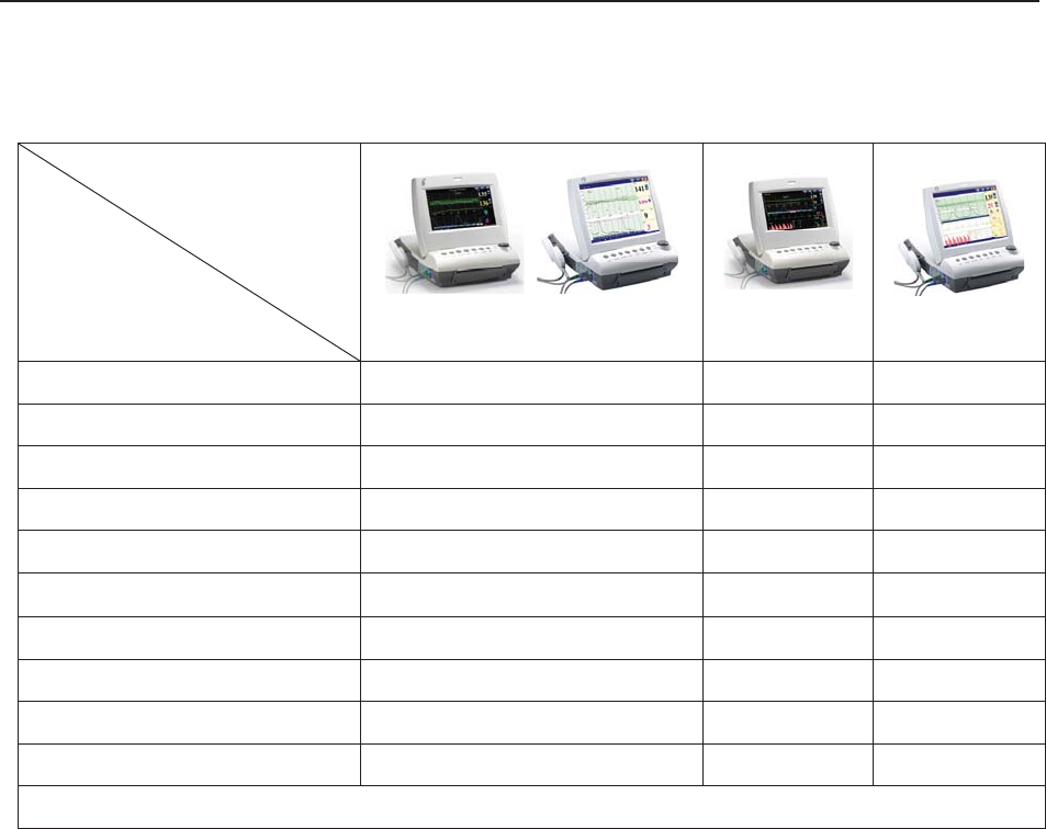
The following table lists the measurements that F6, F6 Express, F9 and F9 Express support.
Model
Measurement
F6, F9
F6 Express
F9 Express
Single-FHR ¥ ¥ ¥
Dual-FHR ¥ ¥ ¥
TOCO ¥ ¥ ¥
FM ¥ ¥ ¥
AFM ¥ ¥ ¥
DECG/IUP Opt
× Opt
MECG × ¥ ¥
NIBP × ¥ ¥
MSpO2 × ¥ ¥
TEMP × ¥ ¥
NOTE: ¥ = Standard Opt = Optional × = Not Available
1.3 Instruction for Safe Operation
NOTE:
In this manual, Monitor refers to F6, F6 Express, F9 and F9 Express, and is used
where the information applies to all models.
The monitor is designed to comply with the international safety requirements IEC/EN
60601-1 for medical electrical equipment. It is class I equipment.
The monitor operates within specifications at ambient temperatures between +5ºC (+41ºF)
and +40ºC (+104ºF). Ambient temperatures that exceed these limits could affect the
accuracy of the instrument and cause damage to the modules and circuits. Allow at least 2
inches (5 cm) clearance around the instrument for proper air circulation.
You must check that the equipment, cables and transducers do not have visible evidence of
damage that may affect patient safety or monitoring capability before use. If damage is
evident, replacement is recommended before use.
The monitor must be serviced only by authorized and qualified personnel. The manufacturer

F Series Fetal & Maternal Monitor User Manual Safety Guide
- 3 -
does not accept responsibility for safety compliance, reliability and performance if
modifications or repairs are carried out by unauthorized personnel. Identical replacement
parts must be used.
The protective degree against electric shock of the patient connections is:
Ultrasound (FHR1, FHR2)
External TOCO
Fetal Movement Mark (FM)
Intrauterine Pressure (IUP)
Type BF
Non-invasive Blood Pressure (NIBP)
Arterial Oxygen Saturation (SpO2)
Type BF, defibrillation-proof
Direct Electrocardiography (DECG) Type CF
Electrocardiography (ECG)
Temperature (TEMP)
Type CF, defibrillation-proof
The monitor described in this user manual is not protected against:
a) The effects of high frequency currents
b) The interference of electrosurgery equipment
1.4 Ultrasound Safety Guide
Fetal Use
The monitor is designed for continuous fetal heart rate monitoring during pregnancy and labor.
Clinical interpretation of fetal heart rate traces can diagnose fetal and/or maternal problems and
complications.
Instructions for Use in Minimizing Patient Exposure
The acoustic output of the monitor is internally controlled and can not be varied by the operator
in the course of the examination. The duration of exposure is, however, fully under the control of
the operator. Mastery of the examination techniques described in the User Manual will facilitate
obtaining the maximum amount of diagnostic information with the minimum amount of exposure.
The exercising of clinical judgment in the monitoring of low risk patients will avoid unnecessary
insonation.

F Series Fetal & Maternal Monitor User Manual Safety Guide
- 4 -
1.5 Safety Precautions
WARNING and CAUTION messages must be observed. To avoid the possibility of injury,
observe the following precautions during the operation of the instrument.
WARNING
For using safety:
1 The monitor or FTS-3 telemetry system (hereinafter called FTS-3) is provided for the
use of qualified physicians or personnel professionally trained.
2 Only qualified service engineers can install this equipment. Only service engineers
authorized by the manufacturer can open the shell.
3 The monitor is not intended for use in intensive care units (ICU), operating rooms or
for home use.
4 Do not switch on the monitor until all cables have been properly connected and
verified.
5 EXPLOSION HAZARD - Do not use the monitor in the presence of flammable
anesthetics or other materials.
6 SHOCK HAZARD - The power receptacle must be a three-wire grounded outlet.
Never adapt the three-prong plug from the monitor to fit a two-slot outlet. A hospital
grade outlet is required. If the outlet has only two slots, make sure that it is replaced
with a three-slot grounded outlet before attempting to operate the monitor.
7 SHOCK HAZARD - Do not attempt to connect or disconnect a power cord with wet
hands. Make certain that your hands are clean and dry before touching a power
cord.
8 Do not touch accessible parts of non-medical electrical equipment and the patient
simultaneously. Do not touch the signal input or output connector and the patient
simultaneously.
9 Accessory equipment connected to the analog and digital interfaces must be
certified according to the respective IEC/EN standards (e.g. IEC/EN 60950 for data
processing equipment and IEC/EN 60601-1 for medical equipment). Furthermore all
configurations shall comply with the valid version of the system standard IEC/EN
60601-1-1. Anybody who connects additional equipment to the signal input
connector or signal output connector to configure a medical system must ensure that
the system complies with the requirements of the valid version of the system
standard IEC/EN 60601-1-1. If in doubt, consult our technical service department or
your local distributor.
10 Do not exceed the maximum permitted load when using multiple portable
socket-outlets to supply the system.

F Series Fetal & Maternal Monitor User Manual Safety Guide
- 5 -
WARNING
11 SHOCK HAZARD – Do not connect non-medical electrical equipment, which has
been supplied as a part of the system, directly to the wall outlet when the
non-medical equipment is intended to be supplied by a multiple portable
socket-outlet with an isolation transformer. If multiple instruments are connected to a
patient, the sum of the leakage currents may exceed the limits given in the IEC/EN
60601-1 and may pose a safety hazard. Consult your service personnel.
12 Do not connect any equipment or accessories that are not approved by the
manufacturer or that are not IEC 60601-1 approved to the monitor. The operation or
use of non-approved equipment or accessories with the monitor is not tested or
supported, and monitor operation and safety are not guaranteed.
13 Do not apply this monitor and other ultrasonic equipment simultaneously on a same
patient, in case of possible hazard caused by leakage current superposition. Do not
apply this monitor simultaneously with other PATIENT-connected equipment, such
as, a cardiac pacemaker or other electrical stimulators, on the same patient.
14 The monitor can only be used on one patient at a time.
15 SHOCK HAZARD - Do not remove the top panel cover during operation or while
power is connected. Only authorized service personnel could remove the unit cover.
16 Equipment and devices that connect to the monitor should form an equipotential
body to ensure effective grounding.
17 Only connect accessories supplied or recommended by the manufacturer to the
device.
18 The system should be operated by the doctor or under the doctor’s instructions.
19 Do not apply the monitor during electro-surgery or MRI; otherwise it might result in
harming the patient or the operator.
20 Only MECG, SpO2, NIBP and TEMP applied parts of the monitor are
defibrillation-proof. When a defibrillator is applied, keep other accessories away from
the patient. Otherwise it may result in damaging the monitor or harming the patient.
21 ECG cables may be damaged when connected to a patient during defibrillation.
Check cables for functionality before using them again.
22 After defibrillation, the screen display recovers within 10 seconds if the correct
electrodes are used and applied based on the manufacturers’ instructions.
23 Any non-medical equipment (such as the external printer) is not allowed to be used
within the patient vicinity (1.5m/6ft.).

F Series Fetal & Maternal Monitor User Manual Safety Guide
- 6 -
WARNING
24 Make sure that the power is turned off and the power cord is disconnected from the
AC socket before connecting or disconnecting equipment. Otherwise, the patient or
operator may receive electrical shock or other injury.
25 Disconnect power cord before changing fuses. Replace them with those of the same
specifications only.
26 Parts and accessories used must meet the requirements of the applicable IEC 601
series safety standards, and/or the system configuration must meet the requirements
of the IEC 60601-1-1 medical electrical systems standard.
27 Connect the grounding wire to the equipotential grounding terminal in the main
system. If it is not evident from the instrument specifications whether a particular
instrument combination is hazardous or not, for example due to summation of
leakage currents, you should consult the manufacturer or an expert in the field, to
ensure that the necessary safety of all instruments concerned will not be impaired by
the proposed combination.
For proper monitoring:
28 The monitor is not intended for treatment.
29 Alarms must be set up according to different situations of patients. Make sure that
audio sounds can be activated when an alarm occurs.
30 Do not perform NIBP measurements on patients with sickle-cell disease or under
any condition where the skin is damaged or expected to be damaged.
31 Clinical decision making based on the output of the device is left to the discretion of
the provider.
32 Do not put the sensor on extremities with arterial catheter or venous syringe.
33 Do not apply the cuff to a limb that has an intravenous infusion or catheter in place.
This could cause tissue damage around the catheter when infusion is slowed or
blocked during cuff inflation.
34 The fetal spiral electrode and intrauterine pressure catheter are disposable. Discard
them after use.
35 The disposable accessories are intended to be used only once. Dispose of them
properly after use and do not reuse them.
36 The IUPC is neither intended nor approved for measuring intrauterine pressure
extraovularly; attempting to do so may lead to maternal discomfort or injury.
For using the battery:
37 Before using the rechargeable lithium-ion battery (hereinafter called battery), be sure
to read the user manual and safety precautions thoroughly.

F Series Fetal & Maternal Monitor User Manual Safety Guide
- 7 -
WARNING
38 Use the battery only in F6 / F6 Express / F9 / F9 Express.
39 Do not reverse the battery pole or it will cause explosion.
40 Do not unplug the battery when monitoring.
41 Do not heat or throw the battery into a fire.
42 Do not use or leave battery close to fire or other places where the temperature may
be above +60 ºC (+140 ºF).
43 Do not immerse, throw, or wet the battery in water/ seawater.
44 Do not destroy the battery: Do not pierce battery with a sharp object such as a
needle. Do not hit with a hammer, step on or throw or drop to cause strong shock.
Do not disassemble or modify the battery.
45 Do not short-circuit the battery by connecting the battery cable connector or battery
socket with metal objects or solder.
46 If the liquid leak from the battery spills onto your skin or clothes, wash well with fresh
water immediately.
47 If the liquid leak from the battery gets into eyes, do not rub the eyes. Wash them well
with clean water and see a doctor immediately.
48 Do not solder the leading wire and the battery terminal directly.
49 Keep the battery away from fire immediately when leakage or foul odor is detected.
50 Stop using the battery if abnormal heat, odor, discoloration, deformation or abnormal
condition is detected during use, charge, or storage. Keep it away from the monitor.
51 Do not use a battery with serious scar or deformation.
52 Remove the battery and store it at a cool and dry environment if the monitor is not
used for a long time.
53 Unplug the monitor before installing and removing the battery.
54 Do not connect the battery directly to an electric outlet or cigarette lighter charger.
55 Batteries have life cycles. If the time that the monitor using battery becomes much
shorter than usual, the battery life is at an end. Replace the battery with a new one
of the same specification as the one provided or recommended by the manufacturer.
56 If the battery is stored alone and not used for a long time, we recommend that the
battery should be charged at least once every 6 months to prevent overdischarge.
In addition, when you use the FTS-3 fetal telemetry system, please pay attention to the
warnings as follows:
57 The system should be operated by the doctor or under the doctor’s instructions.

F Series Fetal & Maternal Monitor User Manual Safety Guide
- 8 -
WARNING
58 SHOCK HAZARD – The base station and transducers for one patient must be
supplied by the same power and do not change the power supply.
59 Please arrange a function test periodically for the system.
60 Do not move the system when it is powered on and do not soak it in any liquid.
61 Please check the transducer, cable and base station periodically. If the transducers
are damaged, do not use them in water and repair them in time.
62 If the transducer has been beaten or knocked, please check whether the cover is
airproof or damaged. If you have any doubt, please contact the manufacturer or local
agent.
63 If the battery in the base station is stored alone and not used for a long time, we
recommend that the battery should be charged at least once every 6 months to
prevent overdischarge.
64 The battery in the wireless transducer should be replaced by the serviceman
authorized by EDAN.
65 The wireless transducer has priority over the wired transducer. When the wireless
transducer is working, the wired transducer will be turned off automatically. Do not
use the wireless transducer and the wired transducer at the same time.
CAUTION
1 The device is designed for continuous operation. Avoid liquid splashing on the
device.
2 Refer servicing to qualified personnel.
3 Keep the environment clean. Avoid vibration. Keep it far from corrosive medicine,
dust area, high-temperature and humid environment.
4 When installing the unit into a cabinet, allow for adequate ventilation, accessibility for
servicing, and room for adequate visualization and operation.
5 Do not operate the unit if it is damp or wet because of condensation or spills. Avoid
using the equipment immediately after moving it from a cold environment to a warm,
humid location.
6 Do not sterilize the monitor or any accessory with autoclave or gas.
7 Switch off the system power before cleaning. Cleaning consists of removing all dust
from the exterior surface of the equipment with a soft brush or cloth.
8 Only the sensor and cable of US/TOCO transducers are watertight. Pay attention not
let any liquid enter the transducer plug.

F Series Fetal & Maternal Monitor User Manual Safety Guide
- 9 -
CAUTION
9 Electromagnetic Interference - Ensure that the environment in which the monitor
or FTS-3 is installed is not subject to any source of strong electromagnetic
interference, such as CT, radio transmitters, mobile phone base stations, etc. Even
though other devices are in accordance with national standard radiation
requirements, the monitor or FTS-3 may be interfered.
10 Electromagnetic Interference - Do not use mobile phones nearby in the process of
monitoring.
11 Electromagnetic Interference - Fetal parameters, especially ultrasound and ECG,
are sensitive measurements involving small signals, and the monitoring equipment
contains very sensitive high gain front-end amplifiers. Immunity levels for radiated
RF electromagnetic fields and conducted disturbances induced by RF fields are
subject to technological limitations. To ensure that external electromagnetic fields do
not cause erroneous measurements, it is recommended to avoid the use of
electrically radiating equipment in close proximity to these measurements.
12 Electromagnetic Interference - The monitor or FTS-3 system should not be used
adjacent to or stacked with other equipment, refer to section A7.4 Recommended
Separation Distances.
13 Electromagnetic interference is not unique to this system but is characteristic of fetal
patient monitoring equipment in use today. This performance is due to very sensitive
high gain front-end amplifiers required to process the small physiological signals
from the patient. Among the various monitoring systems already in clinical use,
interference from electromagnetic sources is rarely a problem.
14 The medical electrical equipment needs to be installed and put into service
according to Appendix 7 EMC Information.
15 Portable and mobile RF communications equipment can affect medical electrical
equipment, refer to section A7.4 Recommended Separation Distances.
16 Sterility cannot be guaranteed if package of the fetal spiral electrode is broken or
opened.
17 The fetal spiral electrode has been sterilized by gamma radiation. Do not re-sterilize.
18 The device and reusable accessories could be sent back to the manufacturer for
recycling or proper disposal after their useful lives.
19 If the terminals of the battery become dirty, wipe with a dry cloth before using the
battery.
20 For information on installing and removing the battery from the monitor, thoroughly
read the user manual.

F Series Fetal & Maternal Monitor User Manual Safety Guide
- 10 -
CAUTION
21 The device and accessories are to be disposed of according to local regulations after
their useful lives. Alternatively, they can be returned to the dealer or the
manufacturer for recycling or proper disposal. Batteries are hazardous waste. Do
NOT dispose them together with house-hold garbage. At the end of their life hand
the batteries over to the applicable collection points for the recycling of waste
batteries. For more detailed information about recycling of this product or battery,
please contact your local Civic Office, or the shop where you purchased the product.
22 Batteries have life cycles. If the time that the monitor and the FTS-3 system using
battery becomes much shorter than usual, the battery life is at an end. Please
contact the manufacturer to replace the battery with a new one of the same
specifications as the one provided or recommended by the manufacturer.
In addition, when you use the FTS-3 fetal telemetry system, please pay attention to the
cautions as follows:
1 The wireless transducers are IPX8 waterproof, but the base station should be kept
non-soaked and non-condensing. The system may be condensing during
transportation in high humidity or low temperature.
2 The water temperature must not exceed +60 ºC (+140 ºF) when you wash the belt.
3 The use of accessories and cables other than those specified may result in
increased electromagnetic emissions or decreased electromagnetic immunity of the
system.
4 This equipment generates, uses and radiates radio-frequency energy, and if it is not
installed and used in accordance with its accompanying documentation, it may
cause interference to radio communications.
5 When the battery is charged, used or stored, keep it away from objects or materials
with static electric charges.
6 If the terminals of the battery become dirty, wipe with a dry cloth before using the
battery.
7 The recommended charging temperature for the battery is between 0°C ~ +40°C.
Please do not exceed the temperature range.
8 Batteries have life cycles. If the time that FTS-3 using battery becomes much shorter
than usual, the battery life is at an end. Please contact the manufacturer to replace
the battery with a new one of the same specification as the one provided or
recommended by the manufacturer.
9 Remove the battery in the base station and store it at a cool and dry environment if
the system is not used for a long time.
10 Please remove the battery out of the transducer at the end of their life.
11 Please read the user manual carefully when you install or remove the battery.

F Series Fetal & Maternal Monitor User Manual Safety Guide
- 11 -
CAUTION
12 Operation is subject to the following two conditions: (1) This device may not cause
harmful interference, and (2) this device must accept any interference received,
including interference that may cause undesired operation.
13 Any Changes or modifications not expressly approved by the party responsible for
compliance could void the user's authority to operate the equipment.
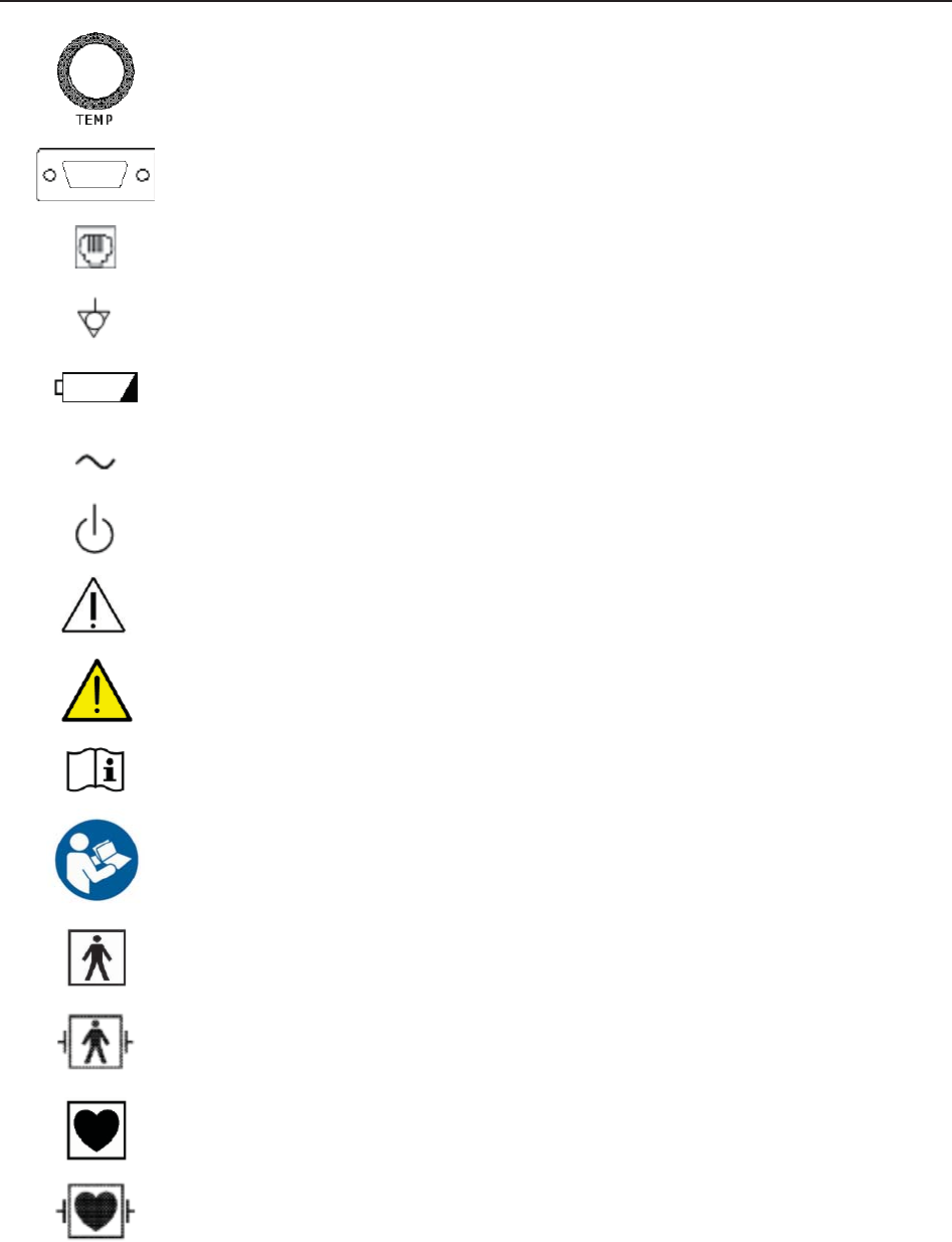
1.6 Definitions and Symbols
Socket for ultrasound transducer 1 (Type BF applied part)
Socket for ultrasound transducer 2 (Type BF applied part)
Socket for DECG cable (Type CF applied part)
Socket for TOCO transducer or IUP cable (Type BF applied part)
Socket for Remote Event Marker (Type BF applied part)
Reserved.
Socket for NIBP Cuff (Type BF applied part)
Socket for SpO2 Sensor (Type BF applied part)
Socket for Maternal ECG Cable (Type CF applied part)
F Series Fetal & Maternal Monitor User Manual Safety Guide
- 12 -
Socket for TEMP Sensor (Type CF applied part)
RS232 Interface (DB9 or D-Sub)
RJ45 Interface
Equipotential Grounding
Battery check
Alternating Current (a.c.)
Stand-by
Caution, consult ACCOMPANYING DOCUMENTS
Warning
Operating instructions
Follow instructions for use
Type BF applied part
Defibrillation-proof type BF applied part
Type CF applied part
Defibrillation-proof type CF applied part
IPX1 Protected against vertically falling water drops
IPX8 Protected against the effects of continuous immersion in water
F Series Fetal & Maternal Monitor User Manual Safety Guide
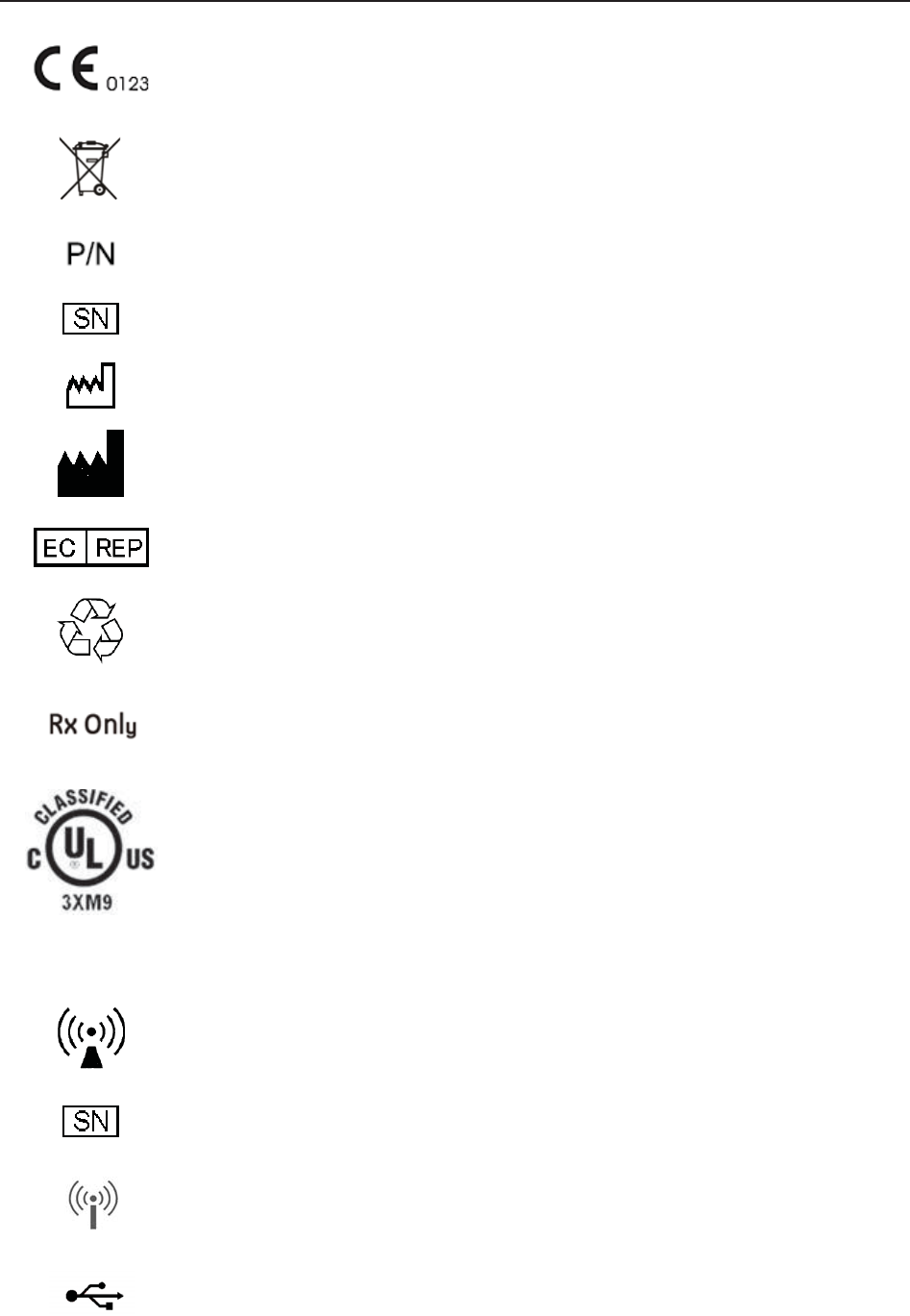
- 13 -
CE marking
Disposal method
Part Number
Serial Number
Date Of Manufacture
Manufacturer
Authorized Representative in the European Community
General symbol for recovery/recyclable
Caution: Federal (U.S.) Law restricts this device to sale by or on the order of
a physician
With respect to electrical shock, fire and mechanical hazards only in
accordance with UL 60601-1and CAN/CSA C22.2 No. 601.1
FTS-3 Fetal Telemetry System
Non-ionizing electromagnetic radiation
Serial Number
Wireless Transducer Working Indicator
USB Port (Reserved)

F Series Fetal & Maternal Monitor User Manual Safety Guide
- 14 -
Ethernet Port (Reserved)
Channel Adjustment

F9, F9 Express Fetal & Maternal Monitor User Manual Installation Guide
- 15 -
Chapter 2 Installation Guide
NOTE:
Installation must be carried out by qualified personnel authorized by the manufacturer.
2.1 Opening and Checking Package
Visually examine the package prior to unpacking. If any signs of mishandling or damage are
detected, contact the carrier to claim for damage.
Open the package; take out the monitor and accessories carefully. Keep the package for possible
future transportation or storage. Check the components according to the packing list.
Check for any mechanical damage.
Check all the cables and accessories.
If there is any problem, contact us or your local distributor immediately.
2.2 Installing Battery
WARNING
Switch off the monitor and unplug it before installing or removing the battery.
If your monitor has been configured with a rechargeable lithium-ion battery, follow these steps to
install the battery:
(1) Battery Installation
1) Carefully place the monitor upside down on a flat surface covered with cloth or other type of
protecting pad.
2) Remove the screws of the battery compartment using a cross-head screw driver. Remove the
battery compartment cover.
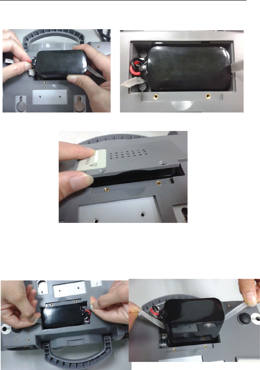
F9, F9 Express Fetal & Maternal Monitor User Manual Installation Guide
- 16 -
3) Take the battery out from package. Put the battery and the cables into the battery
compartment and insert the cable connector into the socket.
4) Shut the battery compartment cover and fix the screws.
(2) Battery Removal
Fold the LCD display completely flat before turning the monitor upside down. Remove the
battery in reverse order. To remove the battery, hold the two bands of the battery tight, shake it
loose and pull it out with force.

F Series Fetal & Maternal Monitor User Manual Installation Guide
- 17 -
NOTE:
1 If a rechargeable battery is outfitted, charge it fully each time after using the device to
ensure the electric power is enough.
2 After the device is transported or stored for a long time, charge the battery fully before
use. Connecting to power supply will charge the battery no matter if the monitor is
powered on.
3 Do not pull the battery cables, or the battery may become damaged.
2.3 Installing Monitor
The monitor can be placed on a flat surface, or be installed on a wall or a trolley. The service
engineer should install the monitor properly.
2.4 Connecting Power Cable
Make sure the AC power supply of the monitor complies with the following specification:
100V-240V~, 50Hz/60Hz.
Apply the power cable provided with the monitor. Plug one end of the power cable to the
power socket of the monitor. Connect the other end to a three-slot power output special for
hospital usage.
The equipotential grounding terminal is provided for the connection of a potential
equalization conductor. Therefore, it is recommended to connect the grounding terminal of
the monitor and the power outlet with the grounding wire, making sure the monitor is
grounded.
WARNING
If the protective grounding (protective earth) system is doubtful, the power of the monitor
must be supplied by internal power supply only.
NOTE:
1 Make sure the monitor and the power outlet are placed at a place where it is easy to
connect and disconnect the power cord.
2 When the supply mains is interrupted, the device switches to internal power supply
and operates normally if the battery is installed. If the battery is not installed, the
monitor shuts down and resumes the previous settings at the subsequent operation.
F Series Fetal & Maternal Monitor User Manual Monitor and Accessories
- 18 -
Chapter 3 Monitor and Accessories
3.1 Overview
NOTE:
F6/F6 Express differs from F9/F9 Express in LCD size. This manual takes pictures and
interfaces of F9/F9 Express as an example, and they may look slightly different from
your model.
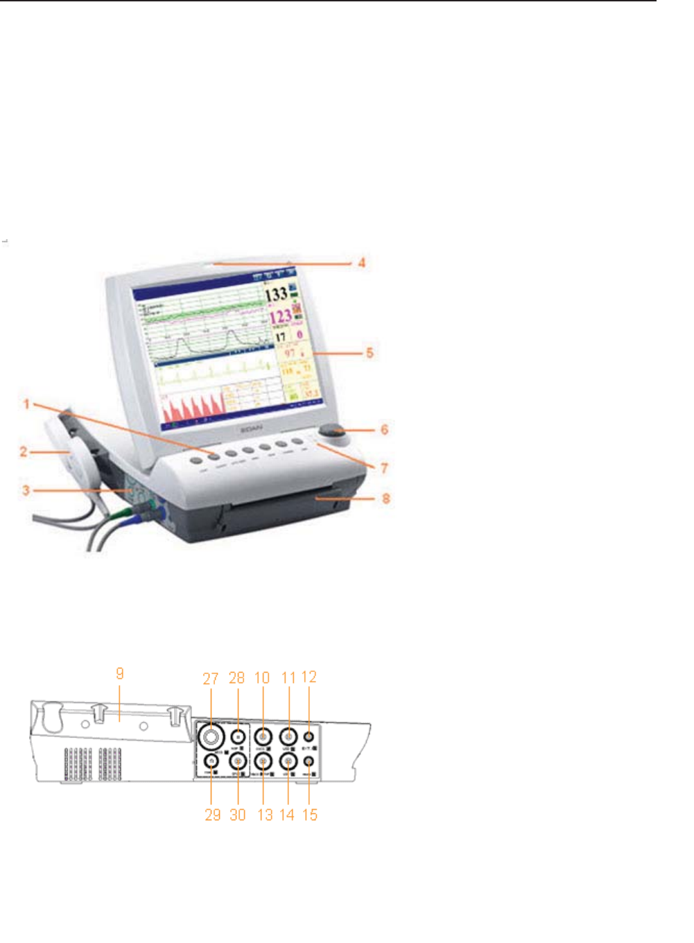
Figure 3-1 Appearance (for reference only)
Figure 3-2 Left Panel
9 Transducer Holder
10 DECG Socket
11 US2 Socket
12 EXT.1 Socket
13 TOCO/IUP Socket
14 US1 Socket
15 MARK Socket
27 MECG Socket
28 NIBP Socket
29 TEMP Socket
30 S
p
O2 Socket
1 Keys
2 Transducer
3 Sockets
4 Alarm Indicator
5 Display Screen
6 Control Knob
7 Charge, AC, Power Indicator
8 Paper Drawer
F Series Fetal & Maternal Monitor User Manual Monitor and Accessories
- 19 -
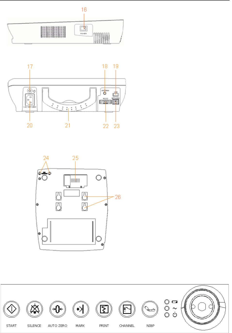
Figure 3-3 Right Panel
Figure 3-4 Rear Panel
Figure 3-5 Bottom Panel
3.1.1 Keys and Control Knob
Figure 3-6 Keys and Control Knob
1
6
P
O
WER
S
witch
24 Fuses
25 Battery Compartment
2
6
Wall-mountin
g
Holes
17 Equipotential Grounding
Terminal
18 Antenna (Not applicable)
19 USB Socket (Not applicable)
20 Power Socket
21 Handle
22 DB9 Socket
23 RJ45Socket

F Series Fetal & Maternal Monitor User Manual Monitor and Accessories
- 20 -
The Monitor is a user-friendly device with operation conducted by a few keys on the front panel
and the control knob. Their functions are as follows:
(1) *START
Function: Start monitoring or return to the main interface
Press this key to start monitoring (on the main interface) or return to main interface (in maternal
information inputting menu or setup menus).
(2) SILENCE
Function: Silence/reset
Press this key to disable the current auditory alarm manifestation, and re-enable the monitor’s
response to new abnormal patient condition.
(3) AUTO ZERO
Function: TOCO zero
Adjust the external TOCO contractions trace/value to preset unit (external monitoring
contractions) or the IUP trace/value to reference point 0 (internal monitoring contractions).
(4) MARK
Function: Record an event.
Press this key to make an event mark.
(5) PRINT
Function: Start / stop printing
Press this key to toggle between starting and stopping printing.
(6) *CHANNEL
Function: Switch the channels
Press this key to toggle the FH sound between US1 channel and US2 channel.
(7) NIBP
Function: Start or stop a NIBP measurement.
Press this key to inflate the cuff and start a NIBP measurement. During the measuring process, press
this key to cancel the measurement and deflate the cuff.

F Series Fetal & Maternal Monitor User Manual Monitor and Accessories
- 21 -
This function is only available on F6 Express and F9 Express.
(8) CONTROL KNOB
Function: Adjust volume, setup and review control.
It can be pressed like other keys and be rotated clockwise or counterclockwise. All the operations
on the screen or in the menu are completed by using the control knob.
The highlighted rectangular mark on the screen that moves with the rotation of the control knob is
called “cursor”. Operations can be performed in the position on the screen where the cursor stays.
When the cursor is located on a certain item, you can press the control knob to open its submenu
or confirm the operation. Press the control knob again, and the cursor will be able to move around
on the interface/menus.
Operation Procedure:
a) Rotate the control knob to move the cursor to the item you want;
b) Press the control knob;
c) One of the following three results will be achieved:
A menu pops up on the screen, or the menu is replaced by a new one;
A submenu with several options appears on the right of the item. If this item has more
than 8 options, they will be displayed in more than one page. Select PREV to switch to
the previous page, or select NEXT to switch to the next page.
The function operates immediately.
NOTE:
1 The word “select” hereinafter stands for rotating the control knob cursor to an item
and then pressing the knob.
2 If the key sound is enabled, the monitor gives a normal key sound when the operation
is valid, and gives a sharp “Di” sound when the operation is invalid.
CAUTION
This monitor is a normal medical device. Please avoid violent operations such as
continuously pressing the keys or control knob.
3.1.2 Indicators
There are four groups of indicator on top of the screen and the front panel. From the top down
they are: alarm indicator, CHARGE indicator, AC indicator and Power indicator.
F Series Fetal & Maternal Monitor User Manual Monitor and Accessories
- 22 -
Indicator Status of Indicator Meaning
Alarm
Indicator
Flash or light up in yellow An alarm is active.
Off No alarm is active.
Charge
Indicator
On The battery is being charged.
Off No battery or the battery is fully
charged.
AC
Indicator
On The monitor is connected to AC
power supply.
Off The monitor is not connected to AC
power supply.
Power
Indicator
On The monitor is powered on.
Off The monitor is powered off.
3.2 Accessories
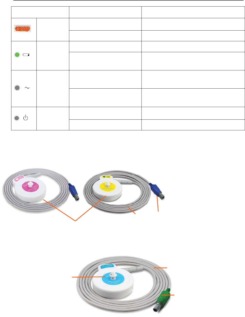
3.2.1 Ultrasound (US) Transducers
Figure 3-7 US Transducers
3.2.2 TOCO Transducers
Figure 3-8 TOCO Transducers
3
1
2
1 US Transducer Sensor
2 Transducer Cable
3 Transducer Connector
3
1
2 1 TOCOS Transducer Sensor
(Blue Labeled)
2 Transducer Cable
3 Transducer Connector

F Series Fetal & Maternal Monitor User Manual Monitor and Accessories
- 23 -
3.2.3 Belt
Figure 3-9 Belt
3.2.4 Remote Event Marker
Figure 3-10 Remote Event Marker
3.2.5 DECG Cable
Figure 3-11 DECG Cable
1
2
1
2
1 DECG Cable Plug
2 DECG Cable Connecto
r
1 Marker Plug
2 Press Key
F Series Fetal & Maternal Monitor User Manual Monitor and Accessories
- 24 -
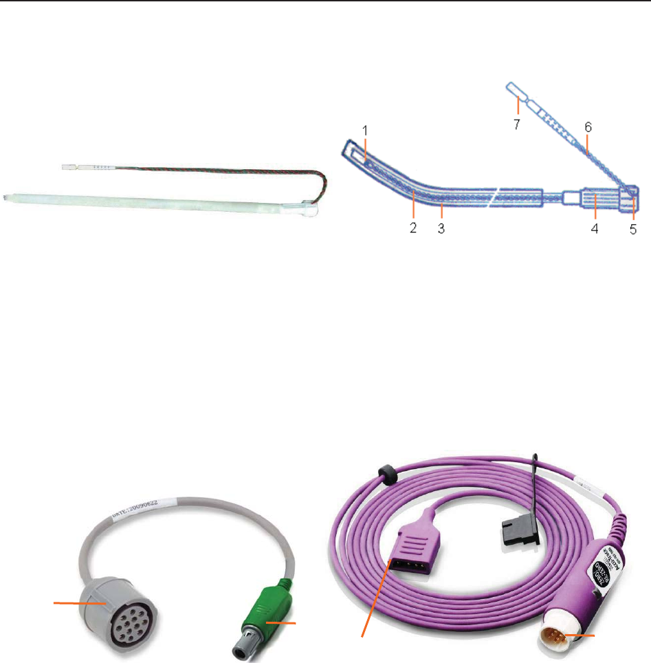
3.2.6 Fetal Spiral Electrode
Figure 3-12 Fetal Spiral Electrode
1 Reference Electrode 2 Drive Tube 3 Guide Tube
4 Drive Handle 5 Handle Notch 6 Electrode Wire
7 Safety Cap
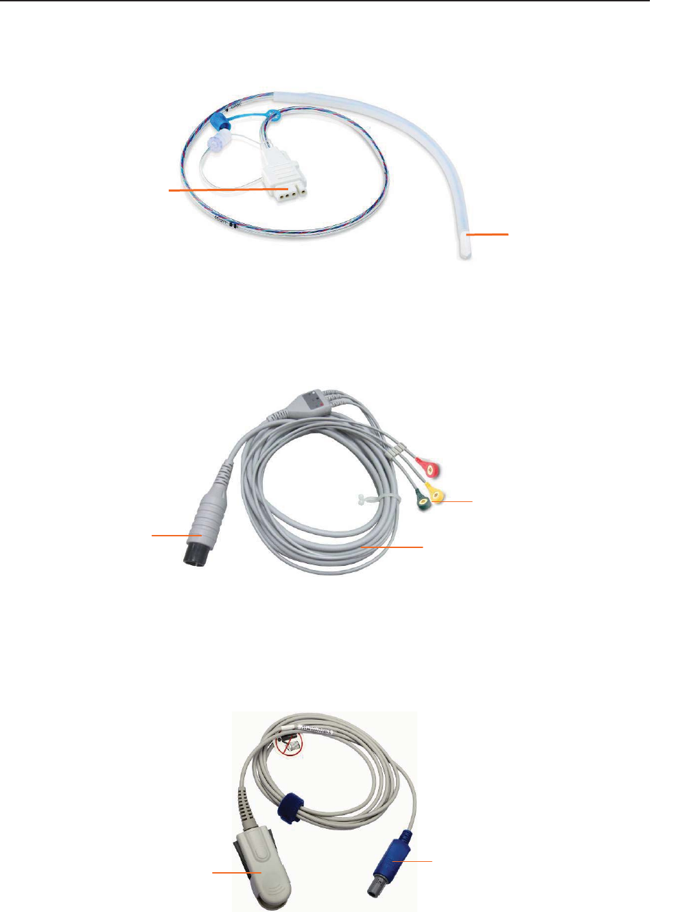
3.2.7 IUP Cable
Figure 3-13 IUP Connecting Cable Figure 3-14 IUP Cable
1 Interface to IUP Cable 2 Connecting plug
3 Interface to IUP Catheter 4 Interface to Connecting Cable
1
2
34
F Series Fetal & Maternal Monitor User Manual Monitor and Accessories
- 25 -
3.2.8 IUP Catheter
Figure 3-15 IUP Catheter
3.2.9 ECG Cable
Figure 3-16 3-Lead ECG Cable
3.2.10 SpO2 Sensor
Figure 3-17 SpO2 Sensor
1
2
1 Interface to IUP Cable
2 Cathete
r
1 ECG Connector
2 ECG Fastener
3 Lead Wire
1 SpO2 Sensor
2 S
p
O
2
Connecto
r
1 2
1
2
3
F Series Fetal & Maternal Monitor User Manual Monitor and Accessories
- 26 -
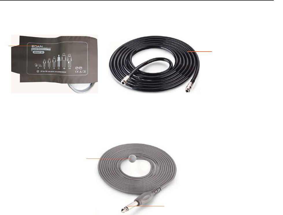
3.2.11 NIBP Cuff
Figure 3-18 NIBP Cuff Figure 3-19 Cuff Extension Tube
3.2.12 TEMP Sensor
Figure 3-20 TEMP Sensor
1 TEMP Sensor
2 TEMP Connector
1
2
1
2
1 NIBP Cuff
2 Cuff Extension Tube
F Series Fetal & Maternal Monitor User Manual Monitor and Accessories
- 27 -
3.3 Screen
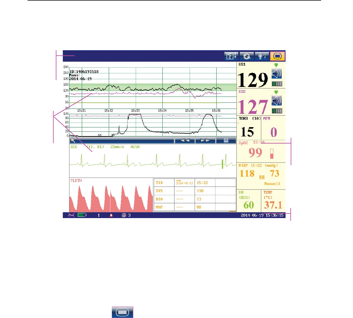
3.3.1 Main Interface
Figure 3-21 Main Interface
*Background Color Switch
The main interface of the monitor displays numbers, traces, menus and monitor status
information. The screen background color has four choices: black, green, orange and blue.
To change the screen color,
1 Select the setup key on the main interface.
2 Select General > Screen Color.
3 Select the required color.
4 Select OK.
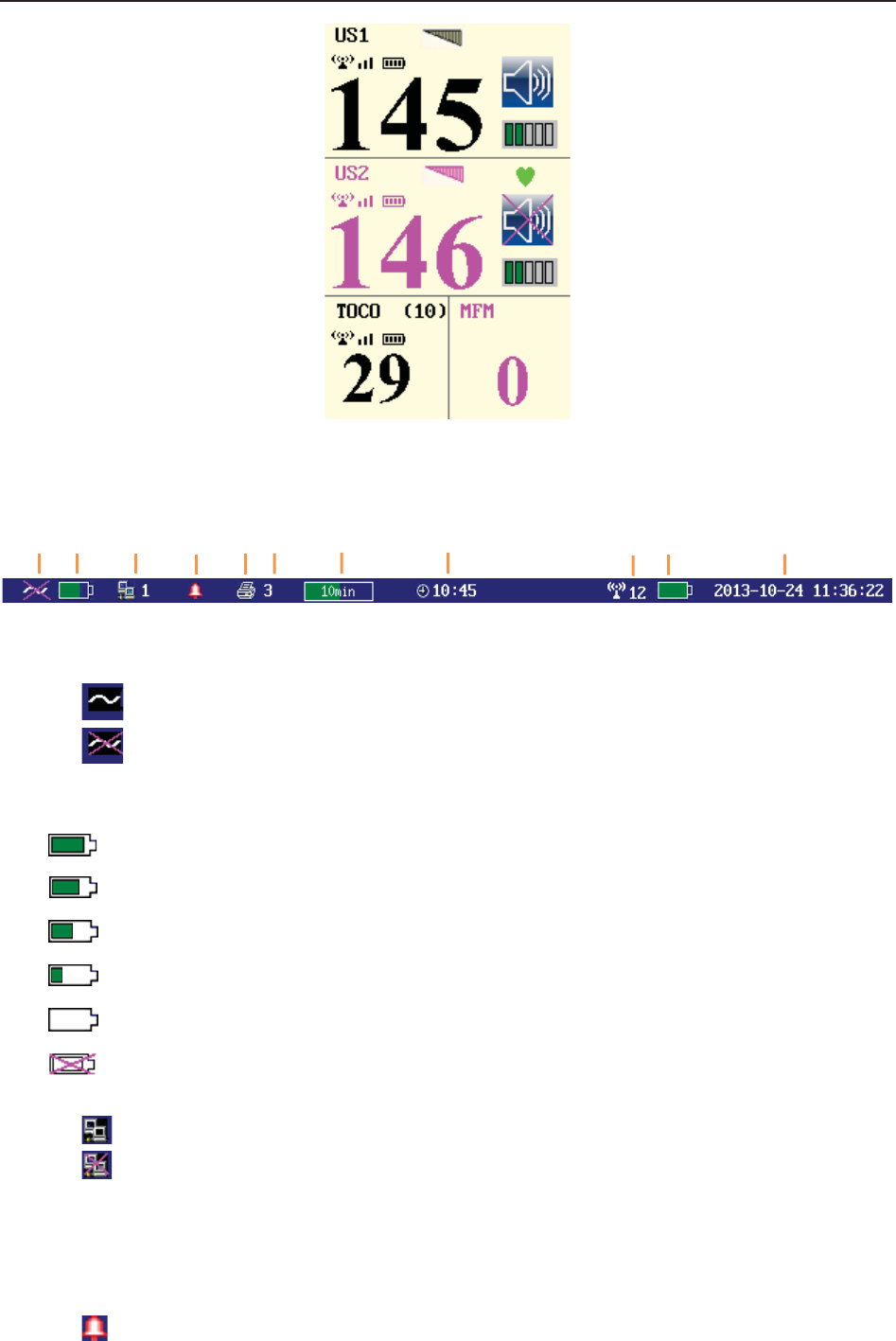
According to the content, the main interface is divided into four windows:
According to the content, the main interface is divided into four windows: (1) Message Window
(2) Trace/ Menu Window (3) Numeric Window (4) Status Window.
Message
Window
Trace/Menu
Window
Numeric
Window
Status Window
F Series Fetal & Maternal Monitor User Manual Monitor and Accessories
- 28 -
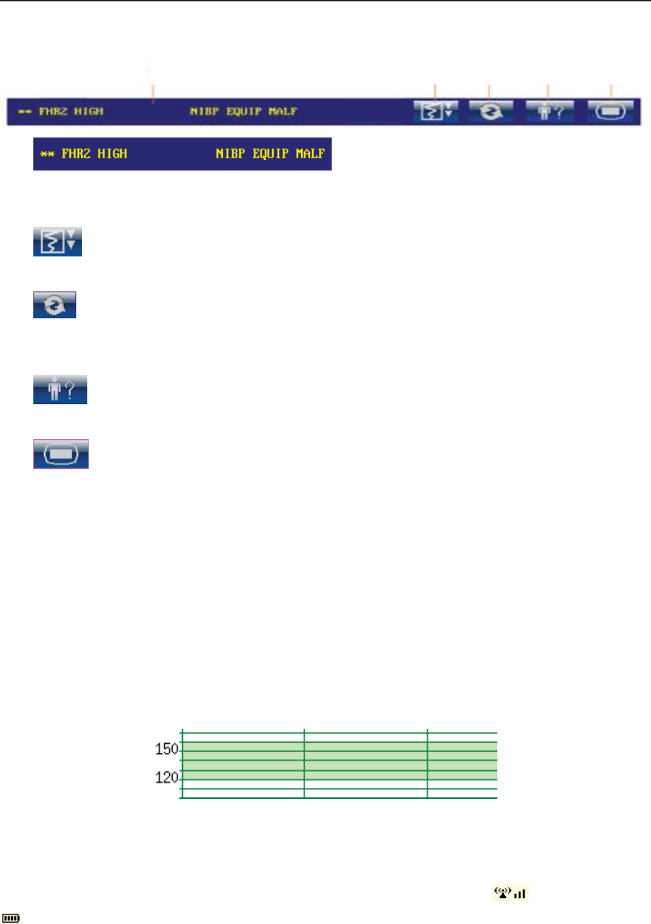
(1) Message Window
a) :
Alarm messages displaying area. When an alarm is active, the message will be displayed
here in yellow. Patient alarms will be displayed on the left and technical alarms in the center.
b) : Paper advancing key. Select this key to advance the paper for 8 cm (PHILIPS
paper) or 7 cm (GE paper).
c) : Display mode switch. F6 Express and F9 Express monitors have three display
modes: maternal-fetal display mode, fetal display mode and maternal display mode. Select
this key, and the display mode will switch to the next one in order.
d) : Mat. Info key. Select this key to open maternal information menu for inputting or
changing the patient’s ID and name.
e) : Setup key. Select this key to open setup main menu.
(2) Trace/Menu Window
The trace/menu window occupies most space of the screen. During monitoring or reviewing, it
displays traces; during setting, it displays setup menus.
The background pane bar supports two standards: 30 ~ 240 (American standard) and 50 ~ 210
(International standard).
The green band in between the fetal heart rate panes indicates the preset alarm range (the top
edge is not higher than 180 and the bottom edge is not lower than 100). It makes it easy to
observe if the FHR exceeds the normal range. So you can easily tell if the fetal heart rate is too
low or too high.
(3) Numeric Window
The fetal monitoring numerics and maternal vital signs are displayed here.
When the monitor is connected to the FTS-3 system, the signal strength and battery level
of the wireless transducers are displayed.
a b c d e
F Series Fetal & Maternal Monitor User Manual Monitor and Accessories
- 29 -
(4) Status Window
f) Power indicator
- AC power supplied.
- no AC power supplied.
g) Battery indicator
The battery is loaded into the monitor with 100% capacity
75% capacity
50% capacity
25% capacity
The battery is almost depleted and needs to recharge immediately.
No battery is loaded.
h) Network connection indicator and device no.
- the monitor is online.
- the monitor is offline.
NOTE:
The network connection indicator is not available if the net version is Insight or
Philips.
i) Audio alarm indicator
- the audible alarm is switched on.
f g h i j k l m n o p

F Series Fetal & Maternal Monitor User Manual Monitor and Accessories
- 30 -
- the current audible alarm is switched off infinitely.
- the current audible alarm is switched off temporarily.
j) Recorder status indicator
- the recorder is in the process of printing.
- no printing is going on.
k) - Print speed.
l) - Print remaining time.
m) - Monitoring timer. It indicates the duration of the current monitoring, and
zeroes when the START key is pressed.
n) - FTS-3 system working channel
o) FTS-3 Base Station Battery indicator
The battery is loaded into the base station with 100% capacity
75% capacity
50% capacity
25% capacity
The battery is almost depleted and needs to recharge immediately.
When there is no battery indicator, it indicates that no battery is installed in the base station.
p) The date and time of the monitor.
3.3.2 Setup Interface
The setup menu is provided to change the monitor configurations and monitoring settings. Press
the Setup key on the main interface to open this menu.
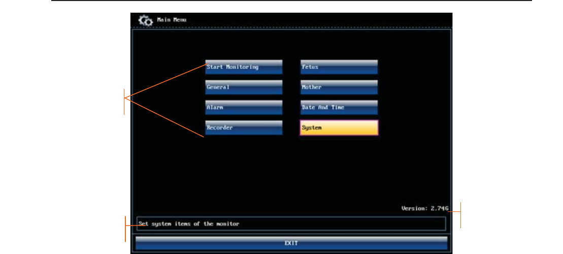
F Series Fetal & Maternal Monitor User Manual Monitor and Accessories
- 31 -
Figure 3-22 Main Setup Menu (F9 Express)
In the setup main menu, you have access to all the items other than System. You can select EXIT
to exit from this menu.
The items in this main menu all have submenu(s). To confirm the setting changes in the
submenus, you need to select OK to exit. If you don’t want to store the new settings, select
Cancel, or press the START key to return to the main interface. If no operation is performed in
30 seconds, the menu will return to the upper directory. The change will not be stored.
Once you select OK to confirm the setting changes, the new settings will be stored in the
monitor’s long-term memory. If the monitor is switched on again after being switched off or a
power loss, it will restore the new settings. The setting does not take effect if the system exits
automatically or is shutdown before OK is selected.
For your reference, when the cursor is located at an item in this menu, the monitor provides a
brief function description of this item in a pane with blue frame under the items. For example, the
cursor is located at “System” in the illustration above. Correspondingly, its function “Set system
items of the monitor” is issued in the blue frame pane.
3.3.3 Touch Screen
As an option, some of F9 and F9 Express may have been configured with a touch screen.
The touch screen is easy to use and operate. It works as a smart control knob. All the operations
of the control knob can be done by gently touching the corresponding position on the screen.
When the touch screen is configured, touching the corresponding menu item is equal to rotating
Function description
Setup Items
Software Version

F Series Fetal & Maternal Monitor User Manual Monitor and Accessories
- 32 -
the control knob to this item and then pressing it. In the same way, one of the three results with
the control knob will be achieved.
On the main interface, the symbols and might appear right next to the highlighted
item. Touch the symbol to increase the numeric, move to the previous item or move
leftwards. While touching the will decrease the numeric, move to the next item or move
rightwards.
To exit from the submenu, you should touch the item again or touch any place outside the area of
the options.
NOTE:
When touching an item, place the finger or the stylus pen within this item’s cursor pane
to ensure the operating validity. A key sound is heard corresponding to every valid touch,
if the key sound is enabled.

F Series Fetal & Maternal Monitor User Manual Alarms
- 33 -
Chapter 4 Alarms
4.1 Alarms Classification
The monitor has two types of alarm: patient alarm and technical alarm.
Patient alarms indicate the situation of vital sign exceeding its configured limit. Audible alarms
and visual alarms can be disabled excluding ASYSTOLE alarm. The adjustable alarm limits
determine the conditions that trigger the alarm.
Technical alarms indicate that the monitor can not measure and therefore can not detect critical
patient conditions reliably. They cannot be disabled.
In terms of severity, the alarms are divided into three levels: high, medium and low. High level
alarm indicates the condition where the patient’s life is endangered; it is a severe warning, labeled
with the symbol ***; Medium level alarm is a moderate warning, labeled with the symbol **;
low level alarm is a general warning.
The high level alarms have highest priority, and the medium level alarms take the second place. If
more than one type of alarms is active at the same time, the monitor sounds an audible indicator
for the higher level alarms.
The alarm levels are preset, and can not be changed.
4.2 Audible Alarm
If the audible alarm is not disabled, the alarm indicator displays . When an alarm is active,
the monitor gives out an alarm sound (the sound pressure range is 45dB ~ 85dB).
High level alarm: a “Do” tone is repeated three times, and then pauses for 3 seconds.
Medium level alarm: a “Do” tone is repeated three times, and then pauses for 5 seconds.
Low level alarm: a “Do” tone is issued, and then pauses for 20 seconds.
Press the SILENCE key, the current audible alarm toggles between on and off (temporarily or
infinitely, you can change the setting).
If the current audible alarm is temporarily disabled, the alarm indicator displays , with a
remaining time on the right. The audible alarm is enabled again when the time is out, or when the
SILENCE key is pressed.
If the current audible alarm is infinitely disabled, the alarm indicator displays (flashing).
The audible alarm is enabled again when the SILENCE key is pressed.
If Alarm Reset is enabled (see 4.8 Pausing or Resetting the Alarm), and you press the SILENCE
key to disable an audible alarm, the alarm indicator will display . When other alarms present,
the monitor will enable the audible alarm again automatically.
During the silence period, the alarm messages are displayed and the alarm indicator lights up as
usual. You can press the SILENCE key again to enable the audible alarm.

F Series Fetal & Maternal Monitor User Manual Alarms
- 34 -
WARNING
1 Do not rely exclusively on the audible alarm system for patient monitoring.
Adjustment of alarm volume to a low level or off during patient monitoring may result
in patient danger. Remember that the most reliable method of patient monitoring
combines close personal surveillance with correct operation of monitoring
equipment.
2 When the sound pressure of audible alarm is equivalent to the ambient noise, it may
be difficult for the operator to distinguish the audible alarm.
3 Do not disable the audible alarm infinitely for the condition where the patient’s safety
may be endangered.
NOTE:
After you enable the audible alarm again, whether the alarm sound still exists depends
on whether the alarm persists.
4.3 Visual Alarm
When an alarm is active,
- Alarm indicator: the alarm indicator lights up:
Alarm Category Indicator Color Flashing Frequency Duty Cycle
High level alarm red 1.4Hz to 2.8Hz 20% to 60% on
Medium level alarm yellow 0.4Hz to 0.8Hz 20% to 60% on
Low level alarm yellow Constant (on) 100% on
- Alarm message: the alarm message appears in the message window of the main interface in
yellow, with patient alarms on the left and technical alarms in the middle.
- Flashing numeric: the numeric of the measurement flashes in grey with a frequency of 2Hz.
When more than one alarm is active, the alarm messages appear in the same area in succession.
The patient alarm messages are displayed either:
in text form, for example “** FHR2 LOW”; or
in numeric form, for example “** FHR2 115 < 120”; ** indicates this is a medium level
alarm event; the first number is the current measurement result; the second number is the
preset alarm limit.
The technical alarm messages are displayed in text form, for example “Fetus EQUIP MALF”.
WARNING
Setting alarm limits to extreme values may cause the alarm system to become
ineffective. It is recommended to use the default settings.

F Series Fetal & Maternal Monitor User Manual Alarms
- 35 -
4.4 Choosing the Alarm Display Form
You can change the patient alarm display form,
1 Select the setup key on the main interface.
2 Select Alarm. On the displayed Password box, enter 9999, then select Enter.
3 Select Message Form.
4 Select Text (default) or Numeric.
5 Select OK.
4.5 Changing the Alarm Volume
You can change the alarm volume,
1 Select the setup key on the main interface.
2 Select Alarm. On the displayed Password box, enter 9999, then select Enter.
3 Select Alarm Volume.
4 Select Low (default), Medium or High.
5 Select OK.
4.6 *Choosing Alarm Silence Duration
You can change the alarm silence duration,
1 Select the setup key on the main interface.
2 Select Alarm. On the displayed Password box, enter 9999, then select Enter.
3 Select Silence Duration.
4 Select Infinite, 1 min (default), 2 min or 3 min.
5 Select OK.
4.7 Choosing Signal Loss Delay
When the fetal signal is lost and this condition continues for a certain time, the monitor issues a
technical alarm. This time (signal loss delay) is adjustable. To change the signal loss delay,

F Series Fetal & Maternal Monitor User Manual Alarms
- 36 -
1 Select the setup key on the main interface.
2 Select Alarm. On the displayed Password box, enter 9999, then select Enter.
3 Select Signal Loss Delay.
4 Select 0 (default) ~ 300 seconds.
5 Select OK.
4.8 Pausing or Resetting the Alarm
You can enable the function of pausing or resetting audible alarms.
1 Select the setup key on the main interface.
2 Select Alarm. On the displayed Password box, enter 9999, then select Enter.
3 Select Audio Alarm.
4 Select Alarm Pause (default) or Alarm Reset.
If Alarm Pause is selected: When the monitor gives out alarm sound and you press the
SILENCE key, the alarm indicator displays , and the alarm sound is muted.
If Alarm Reset is selected: When the monitor gives out alarm sound and you press the
SILENCE key, the alarm indicator displays , and the alarm sound is muted. When
other alarms present, the monitor will enable the audible alarm again automatically.
5 Select OK.
4.9 *Reviewing Alarms
An alarm reviewing menu cannot only record the immediate alarm messages with date and time
information, but also record the historically physiological alarm and signal overlap alarm
messages with date and time information.
The monitor can display a maximum of 100 immediate alarm messages. When the storage is full,
it will delete the earliest alarm message automatically to store the new one.
The monitor can display a maximum of 800 historically physiological alarm and signal overlap
alarm messages. When the total number exceeds 800, the alarms messages cannot be stored.
Select the alarm reviewing key in the message window to open this menu.
When you review the traces with the word REVIEW shown in the background, the alarm
reviewing menu displays historic alarm review. Otherwise, it displays the immediate alarm
review.
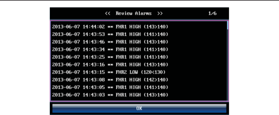
F Series Fetal & Maternal Monitor User Manual Alarms
- 37 -
Each page displays 10 alarm records. The page mark “1/6” informs you that there are 6 pages and
the present one is page 1.
To review more records, select the alarm list and then rotate the control knob to switch to the
previous or next page.
Select OK to exit from this menu.
When a new monitoring starts, or after the monitor is switched off, the alarm messages will be
cleared.
NOTE:
You can select Main Menu > General > Review Alarms to set up On (by default) or
OFF. When the alarm review is enabled, the icon will appear in the main interface.
4.10 Alarm Treatment Measures
During monitoring, make sure there is at least one physician in the area where the alarm sound
can be heard or the alarm messages can be seen, so necessary measures can be taken when an
emergency occurs.
When the monitor gives out an alarm and catches your attention, you should:
- Check the patient’s condition.
- Identify the cause of the alarm.
- Silence the alarm if necessary.
- Check if the alarm is terminated when the alarm condition is solved.
When the monitored parameter(s) come(s) back within the adjusted limits, or if the abnormal
technical condition does not exist any longer, the monitor stops giving out the alarm.

F Series Fetal & Maternal Monitor User Manual Alarms
- 38 -
4.11 Testing Alarms
To test the functions of visible and audible alarms, do the following:
1 Switch on the monitor.
2 Enable the alarm.
3 Set the alarm limits to a small range.
4 Stimulate a signal that is higher than the upper limit or lower than the lower limit. Or
disconnect one of the plugs.
5 Verify if the visible and audible alarms are working properly.
4.12 Patient Alarm Defaults
Alarm Setting Options Default
High Level
ASYSTOLE On (not adjustable) On
Asystole Alarm Delay 0 second (not adjustable) 0 second
Asystole Alarm Level High (not adjustable) High
Medium Level
FHR1/FHR2 Alarm On, Off On
FHR1/FHR2 Low Alarm Limit 60 bpm ~ 205 bpm, in increments of 5 110 bpm
FHR1/FHR2 High Alarm Limit 65 bpm ~ 210 bpm, in increments of 5 160 bpm
FHR1/FHR2 Alarm Delay 0 ~ 30 second(s), in increments of 5 10 seconds
FHR1/FHR2 Alarm Level Medium, not adjustable Medium
HR Alarm On, Off On
HR Low Alarm Limit 30 bpm ~ 239 bpm, in increments of 1 50 bpm
HR High Alarm Limit 31 bpm ~ 240 bpm, in increments of 1 120 bpm
HR Alarm Delay 0 second, not adjustable 0 second
HR Alarm Level Medium, not adjustable Medium
SpO2 Alarm On, Off On
SpO2 Low Alarm Limit 50% ~ 99%, in increments of 1 90%
SpO2 High Alarm Limit 51% ~ 100%, in increments of 1 100%

F Series Fetal & Maternal Monitor User Manual Alarms
- 39 -
SpO2 Alarm Delay 0 second, not adjustable 0 second
SpO2 Alarm Level Medium, not adjustable Medium
SYS Alarm On, Off On
SYS Low Alarm Limit 40 mmHg ~ 269 mmHg, in increments of 1 90 mmHg
SYS High Alarm Limit 41 mmHg ~ 270 mmHg, in increments of 1 160 mmHg
SYS Alarm Delay 0 second, not adjustable 0 second
SYS Alarm Level Medium, not adjustable Medium
DIA Alarm On, Off On
DIA Low Alarm Limit 10 mmHg ~ 214 mmHg, in increments of 1 50 mmHg
DIA High Alarm Limit 11 mmHg ~ 215 mmHg, in increments of 1 90 mmHg
DIA Alarm Delay 0 second, not adjustable 0 second
DIA Alarm Level Medium, not adjustable Medium
TEMP Alarm On, Off On
TEMP Low Alarm Limit 0 ºC ~ +49.9 ºC, in increments of 0.1 +36.0 ºC
TEMP High Alarm Limit +0.1 ºC ~ +50.0 ºC, in increments of 0.1 +39.0 ºC
TEMP Alarm Delay 0 second, not adjustable 0 second
TEMP Alarm Level Medium, not adjustable Medium
NOTE:
The upper limit must be higher than the lower limit. When setting the upper limit, you do
not have access to the options that are lower than the preset lower limit, and vice versa.

F Series Fetal & Maternal Monitor User Manual Printing
- 40 -
Chapter 5 Printing
5.1 *Function Description
The built-in thermal recorder applied in the monitor supports both the American and international
standard wide recorder paper. It prints continuous traces synchronously along with marks.
The monitor supports some other functions listed below:
Auto start printing: If the function is enabled, the recorder starts printing automatically
when new monitoring starts (the START key is pressed). Otherwise you have to press the
PRINT key to start printing.
Printing timer: The printing timer determines the elapsed time for each print. This time is
adjustable. Refer to 5.2.3 Changing the Print Timer.
Remaining time indicating: If the printing timer is set, a process indicator
appears in the status window after printing starts, with the remaining time shown in it. When
the time is up, the monitor gives three “Do” tones and flashes the indicator.
Fast printing: The recorder prints the data saved in the monitor at a high speed (up to
15mm/s).
Data Caching: When the paper drawer runs out of paper or when it is open, the recorder
stops printing. The data from this time on (at most 60 minutes) will be temporarily saved in
the internal memory. When new paper is loaded and/or the drawer is closed, the saved data
will be printed out at a high speed. When the saved trace has been printed out, the recorder
switches back to continue printing the current data at the normal speed automatically.
NOTE:
1 When the monitor is switched off, the data in the internal memory will be lost.
2 If a printing timer is set, and the time is out when the paper runs out, the CTG
analysis result may disaccord with the printout. Therefore, reload the paper in
time to avoid paper lack.
FHR2 offset: You can set the offset of the FHR2 trace to separate the two FH traces on the
screen and the recorder paper. Refer to 7.4.4 Changing FHR2 Offset.
Print self-check: The recorder prints a baseline for self checking when the monitor is
switched on.
Paper advance: When printing stops, press the paper advancing key to advance the
paper, making sure the paper has a perforation outside the drawer and is easy to be torn off.
NOTE:
The paper advancing key is invalid in the process of printing and paper advancing.

F Series Fetal & Maternal Monitor User Manual Printing
- 41 -
5.2 Printing Configuration
NOTE:
All the parameters should be well configured before printing starts. You can not change
the configuration in the process of printing.
5.2.1 Switching Auto Start Printing On or Off
You can switch auto start printing on or off:
1 Select the setup key on the main interface.
2 Select Start Monitoring > PRINT.
3 Select ON or OFF (default).
4 Select OK.
5.2.2 *Choosing the Paper Speed
You can choose a paper speed of 1 cm/min, 2cm/min or 3cm/min:
1 Select the setup key on the main interface.
2 Select Recorder > Print Speed.
3 Select 1 cm/min, 2 cm/min or 3 cm/min (default).
4 Select OK.
NOTE:
Different paper speed setting causes different FHR trace appearance on the record
paper. To avoid misinterpretation, we recommend you to set all monitors in your
institution to the same paper speed.
5.2.3 *Changing the Print Timer
You can choose different time lengths for the print timer:
1 Select the setup key on the main interface.
2 Select Recorder > Timer.
3 Set timer to 10 ~ 90 (minutes, the step is 5) or Infinite (default). For a fixed time, the
recorder stops when the time is up. For Infinite, there is no time limit. Whatever the setting
is, the recorder stops when this patient’s traces come to the end or if the PRINT key is
pressed in midway.
4 Select OK.
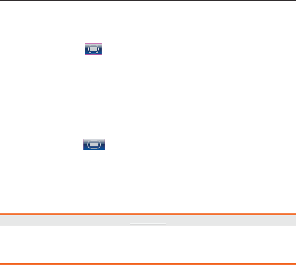
F Series Fetal & Maternal Monitor User Manual Printing
- 42 -
5.2.4 Switching Print Self-Check On or Off
You can switch on or off the print self-check feature:
1 Select the setup key on the main interface.
2 Select Recorder > Print Self-Check.
3 Select ON or OFF (default).
4 Select OK.
5.2.5 Changing Printing End Volume
The monitor gives a tone when printing ends, and this tone volume is adjustable.
1 Select the setup key on the main interface.
2 Select Recorder > Print Ending Beep.
3 Select High, Low (default) or OFF.
4 Select OK.
5.3 Understanding the Recorder Paper Printout
WARNING
1 If there is any discrepancy between the display and the printout, the printout should
prevail.
2 If the data is doubtful, clinicians should make diagnoses based on the real condition.
Figure 5-1 is an example of the recorder paper with traces. Comparing it with the monitor screen,
you can find this extra information on it:
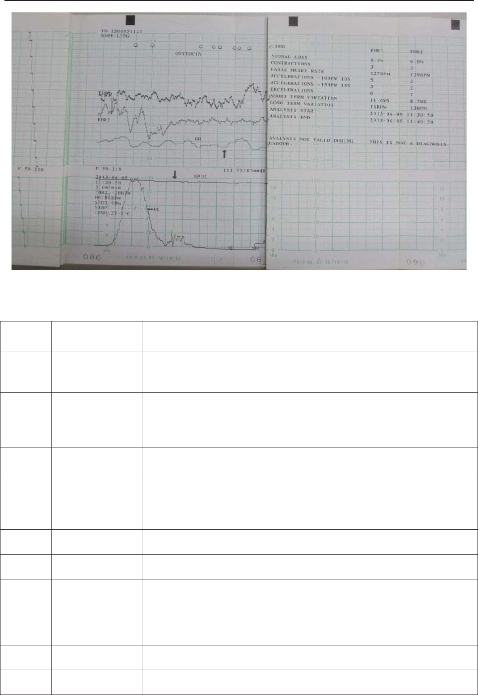
F Series Fetal & Maternal Monitor User Manual Printing
- 43 -
Figure 5-1 An example of recorder paper with traces
Item Information Description
1. Self-Check Trace The monitor prints a self-check trace after being switched on. It is
used to check if the recorder paper is properly loaded.
2. Paper Settings
The paper settings of the monitor. It consists of the paper type and
paper style, e.g. “G 50-210”, indicating that the paper type is “F9-G”,
and the paper style is International. It is printed out to check if the
proper recorder paper is used.
3. Paper Type There are two types of paper: F9-G and F9-P.
4. Paper Style
The FHR pane range indicates the paper style.
American style: 30 ~ 240
International style: 50 ~ 210
5. FHR1 Mark The trace marked with “FHR1” is the FHR1 trace.
6. FHR2 Mark The trace marked with “FHR2” is the FHR2 trace.
7. Trace
Information List
A list of current date, time, print speed, ID, Name, FHR2 offset, HR,
SpO2, NIBP (including SYS and DIA) and TEMP is printed at the start
of the monitoring and every ten minutes afterwards.
8. Smart Note The annotation of the event mark below.
9. HR Mark The trace marked with “HR” is the maternal HR trace.
(
1
)
(
2
)
(
3
)
(
7
)
(
8
)
(
9
)
(
10
)
(
11
)
(
12
)
(
13
)
(
4
)
(5)
(6)
(
14
)

F Series Fetal & Maternal Monitor User Manual Printing
- 44 -
10. SpO2 Mark The trace marked with “SpO2” is the maternal SpO2 trace.
11. NIBP In the real-time printing mode, each NIBP measurement result is
printed on the paper in the order of SYS/DIA.
12. Page Mark Each recorder paper pack has 150 pages. When you notice the page
mark comes to the end, remember to load new paper in time.
13. CTG Analysis
Result The CTG analysis results of FHR1 and FHR2.
14. Alarm Message It indicates the physiological alarm message and signal overlap alarm
message.
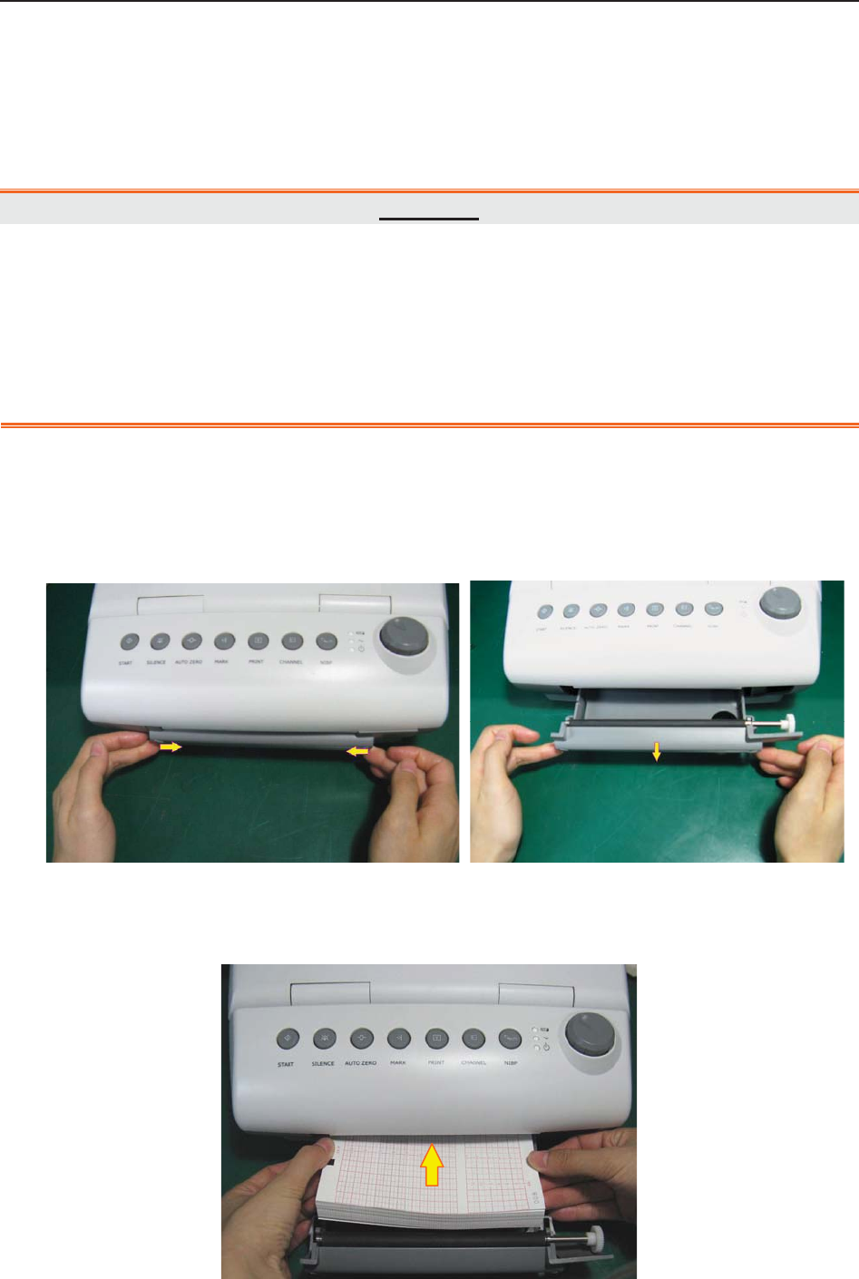
F Series Fetal & Maternal Monitor User Manual Pre-Monitoring Preparation
- 45 -
Chapter 6 Pre-Monitoring Preparation
6.1 Loading Recorder paper
CAUTION
1 Only use the recorder paper provided by the manufacturer, otherwise the recorder
may be damaged. This kind of damage is not covered by warranty.
2 Configured with different hardware, the monitor is compatible with both GE and
Philips recorder paper. However, the monitor is configured with only one type of paper
in the shipment. If you want to use the other type of paper, contact the manufacturer
for service first, otherwise trace excursion or paper jam may occur.
If the monitor is used for the first time or when the paper runs out, you should load paper.
1) Press the two latches on each side of the paper drawer at the same tine and slide the drawer
out carefully.
2) Take out the Z-fold thermosensitive paper and remove the wrapper.
3) Place the pack in the drawer, with the pane facing up and the FHR trace area on the left.
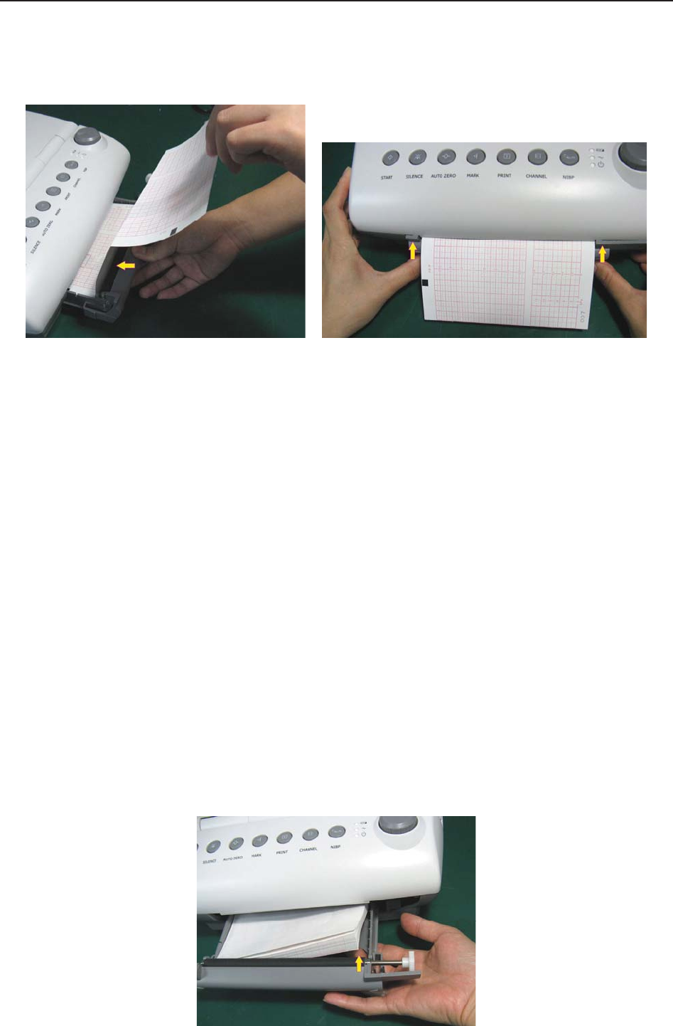
F Series Fetal & Maternal Monitor User Manual Pre-Monitoring Preparation
- 46 -
4) Unfold two sheets from the top of the pack and pull the end of the paper out of the drawer
(make sure the pack in the drawer remains flat).
5) Slide the drawer in until both the latches are locked.
NOTE:
1 Be careful when inserting paper. Avoid damaging the thermosensitive print head.
2 Make sure the paper is evenly loaded in the drawer. Otherwise the data will be
inaccurate or paper jam will happen.
3 Only use the paper the manufacturer approved to avoid poor printing quality,
deflection, or paper jam.
4 Keep the drawer closed unless when loading paper or providing a service.
Removing Paper Jam
When the recorder does not function or sound properly, open the drawer to check for a paper jam.
Remove the paper jam in this way:
1) Cut the recorder paper from the paper drawer edge.
2) Through the hole on the bottom panel of the paper drawer, push the recorder paper up
with one finger. Remove the paper.
3) Reload paper and then close the drawer.

F Series Fetal & Maternal Monitor User Manual Pre-Monitoring Preparation
- 47 -
6.2 Switching On
WARNING
1 Check if all the metal parts are linked to the protective earth cord and the cord is in
good condition before switching on the monitor.
2 If any sign of damage is detected, or the monitor displays some error messages, do
not use it on any patient. Contact biomedical engineer in the hospital or our service
engineer immediately.
Press the POWER switch on the right panel to switch on the monitor. The power indicator lights
up and a start-up music will be heard. You can operate the monitor after the main interface
appears.
You can choose to switch the start-up music on or off,
1 Select the setup key on the main interface.
2 Select General > Start-up Music.
3 Select ON (default) or OFF.
4 Select OK.
6.3 Checking Recorder Paper
The monitor provides the print self-check function to check if the recorder paper is correctly
loaded and set.
The recorder prints a baseline and paper settings after start-up (if Print Self-Check is ON).
Check if the paper settings match the paper being used (in the circled area below, P should
correspond to F9-P, and G to F9-G), and then observe the starts and ends of the printed baselines
(illustrated with the arrow). The starts and ends should be printed exactly on the edges of the pane
if the recorder paper is correctly loaded and set. If they do not comply with the edges, reload
paper or ask the service engineer to check the paper settings of the monitor.
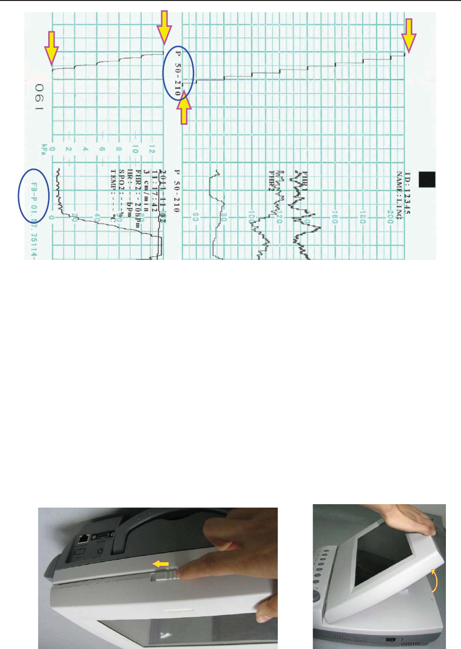
F Series Fetal & Maternal Monitor User Manual Pre-Monitoring Preparation
- 48 -
If the monitor does not print the baseline, switch on the Print Self-Check function and then
restart the monitor.
NOTE:
Make sure the paper is correctly loaded before the printing starts.
6.4 Adjusting Screen Angle
The angle between the screen and the top cover of the monitor is adjustable as needed, allowing it
to be mounted on a wall or placed on a flat surface.
Adjustment method:
Push the hook on top of the screen left to spring it open. Pull the screen forward to adjust to one
of the preset screen angles.
To bring the screen back to flat, pull it all the way forward and then push it back.
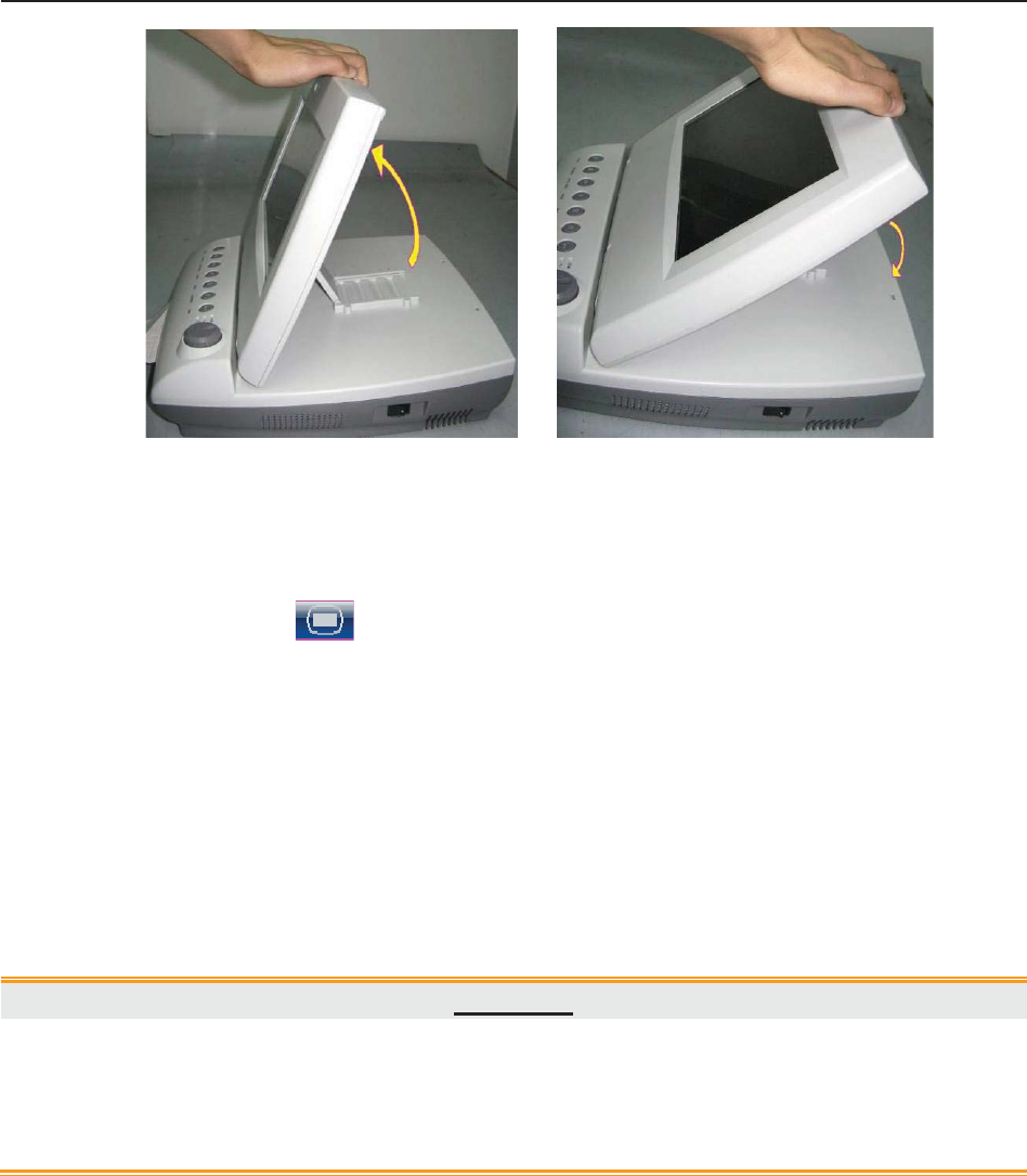
F Series Fetal & Maternal Monitor User Manual Pre-Monitoring Preparation
- 49 -
6.5 Setting Date and Time
You can change the date and time of the monitor,
1 Select the setup key on the main interface.
2 Select Date And Time.
3 Set the year, month, date, hour, minute and second. The first three numbers are used to set
the year, month and date. Their orders vary with the preset Date Format below.
4 Select Date Format for the format of the date; there are three options: yyyy-mm-dd
(default), mm/dd/yyyy and dd/mm/yyyy.
5 Select OK.
CAUTION
You should set date and time information in advance. After this information is changed,
the monitor starts new monitoring with an auto ID. Therefore, we advise you to restart
the monitor after changing date or time information, and do not perform this operation
when monitoring is in process.
NOTE:
The date and time remain in the monitor for at least two months after it is switched off.
You do not have to set date and time before monitoring each time.
6.6 Connecting Transducers
Check for visible damages of the transducers every time before connecting them to the monitor.
Pay special attention to the cracks on the transducers and cables before immersing them into
conductive fluid. If damage is found, replace them with good ones at once.
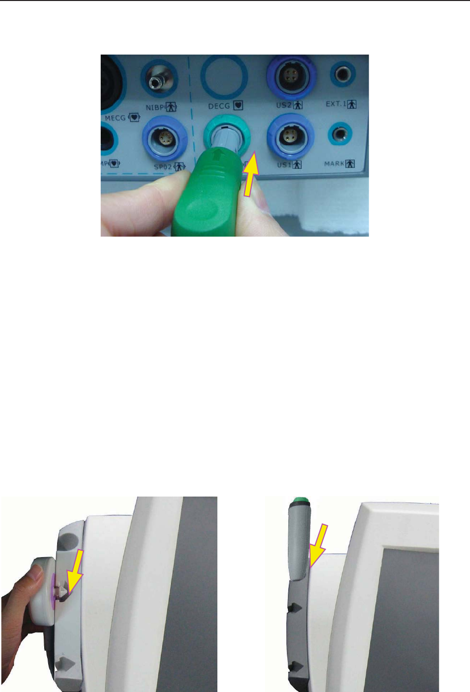
F Series Fetal & Maternal Monitor User Manual Pre-Monitoring Preparation
- 50 -
When plugging transducers into the monitor, make sure the arrow symbol of the connector faces
up and put it into the socket.
When disconnecting a transducer, pinch the afterbody of the transducer plug and pull it out
slightly.
NOTE:
Never try to disconnect the transducer by pulling the cable directly.
6.7 Placing Accessories in the Holder
In order to protect the accessories, place the not-in-use accessories in the holder. The accessory
holder is on the left of the front panel. The first hole from the top is for the remote event marker,
and the rest two are for the transducers.
To place a transducer into the holder, hold the transducer on the edge, and then place the buckle
all the way into one of the holes on the holder. Make sure that the transducer cable is on the
bottom.
To place the remote event marker, put the small end of the marker into the hole as far as it can go.

F Series Fetal & Maternal Monitor User Manual Pre-Monitoring Preparation
- 51 -
NOTE:
In the process of monitoring, the transducer that is placed in the holder may be affected
and thereby produces interfering signals. Therefore, when monitoring a patient, it is
recommended to remove or disconnect the transducer that is not in use.
6.8 Adjusting the Volume
The monitor automatically detects which channel the transducer is connected to. The
corresponding volume adjustment key of this channel displays , indicating the FH sound is
coming out from this channel; while the other one displays , for example:
. Press the CHANNEL key to switch the FH
sound to the other channel.
Adjust the default monitoring volume:
The FH volume returns to the default level after the START key is pressed. This default level is
adjustable. To change this level,
1 Select the setup key on the main interface.
2 Select Start Monitoring > Volum e.
3 Select the volume from 1 ~ 10; the step is 1 and the default level is 3.
4 Select OK.
*Adjust the real-time monitoring volume:
If the default volume level is not satisfactory during monitoring, you can adjust the real-time
volume of each channel.
1 Select the volume adjustment key on the main interface.
2 Rotate the control knob clockwise for one step, the volume increases by one level, there
are ten levels for your choice; the green pane of the volume level indicator
increases by one at every two steps; rotate the knob anticlockwise to decrease the volume.
3 Press the knob again to confirm the volume level.

F Series Fetal & Maternal Monitor User Manual Pre-Monitoring Preparation
- 52 -
*Adjust the key volume:
The volumes of pressing keys, rotating and pressing the control knob are also adjustable.
1 Select the setup key on the main interface.
2 Select General > Key Volume.
3 Select Low (default), High or OFF.
4 Select OK.

F Series Fetal & Maternal Monitor User Manual Fetal Monitoring
- 53 -
Chapter 7 Fetal Monitoring
WARNING
1 The monitor is not intended for use in intensive care units (ICU), operating rooms or
for home use.
2 Do not apply the monitor during electro-surgery or MRI; otherwise it might result in
harming the patient or the operator.
3 Always check if the alarm settings are appropriate for your patient before starting
monitoring.
7.1 Confirming Fetal Life
Fetal monitoring with ultrasound or DECG can not differentiate a fetal heart rate signal source
from a maternal heart rate source in all situations. These are some of the signal sources that might
be taken as FHR signal source by mistake:
- High maternal heart rate signal.
- Maternal aorta or other large vessels signals.
- Electrical impulse from the maternal heart transmitted through a recently deceased fetus.
- Movement of the deceased fetus during or following maternal movement.
So you need to confirm fetal life by other means before starting to use the fetal monitor, such as
using a fetoscope, stethoscope, Pinard stethoscope or obstetric ultrasonography.
7.2 Monitoring FHR with Ultrasound
The ultrasound monitoring is a method to obtain FHR on maternal abdominal wall. Place a US
transducer (Ultrasound transducer) on maternal abdomen. It transmits low energy ultrasound
wave to the fetal heart, and receives the echo signal.
WARNING
Make sure you have confirmed the fetal life by other means before using this monitor for
FHR monitoring.
7.2.1 Parts Required
1) US transducer 2) Aquasonic coupling gel 3) Belt
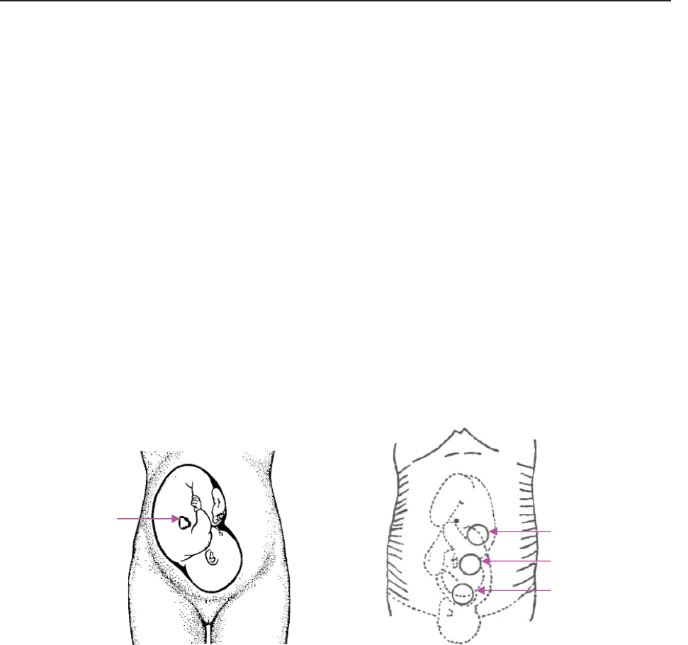
F Series Fetal & Maternal Monitor User Manual Fetal Monitoring
- 54 -
7.2.2 FHR Monitoring Procedure
1) Placing Transducer Belt
Place the transducer belts across the bed, ensuring that the belt will be around the abdomen
when it is fastened. Lay the patient on the bed.
Alternatively, the patient can take a sitting position. Arrange the belt around her abdomen.
2) Determining the Transducer Position
- Determine the fetal position using Leopold’s maneuvers.
- Search for the location of the fetal heart using a stethoscope or a fetoscope. The best fetal
heart signal can be obtained through the fetal back.
- Place the transducer below the navel for head presentation and place the transducer above the
navel for breech presentation.
- During parturition, the fetal heart moves downward as the labor progresses. It is
recommended to move the transducer along with the fetus.
Figure 7-1 Positioning Ultrasound Transducer (single fetus)
3) Acquiring Fetal Heart Signal
Apply a certain amount of acoustic gel on the transducer and move the transducer slowly around
the fetus site to even the gel. The best fetal heart signal can be obtained through the fetal back.
Find at least 2 or 3 sites, and choose the one where the clearest, most sonorous and steady fetal
heart sound is heard. When the transducer is connected correctly and communicated well, the
fetal heart signal indicator is full. If the signal is poor, the signal indicator shows as it is and no
FHR data are displayed. When you move the transducer on the abdomen, adjust the speaker
volume so that it can be clearly heard.
4) Fixing the Transducer
When you find clearest and most steady fetal heart sound, wrap the abdomen with the belt over
the transducer. Fix the transducer by pushing its buckle through the overlapping section of the
belt.
Fetal Heart
Pregnancy
Early Parturition
Late Parturition

F Series Fetal & Maternal Monitor User Manual Fetal Monitoring
- 55 -
Make sure the belt fits the patient snugly but comfortably. Meanwhile, fetus heart beat sound is
heard; the FHR trace and numeric are displayed. During long-time monitoring, the gel may dry
out as the transducer moves around. Add more gel in time if it is inadequate.
5) Confirming that the Fetus is the Signal Source
Ultrasound Doppler technology is utilized to observe the fetal heart rate externally, there are
possibilities that maternal heart rate signal is mistaken for FHR signal. It is highly
recommended to confirm that the fetus is the signal source continuously. You can feel the
maternal pulse at the same time.
If the maternal heart signal is misidentified as the fetal heart signal, Repositioning of the
transducer is needed.
NOTE:
1 Do not mistake the high maternal heart rate for fetal heart rate. The fetal pulse can be
distinguished from the maternal pulse by feeling the mother’s pulse during the
examination.
2 The best quality records will only be obtained if the probe is placed in the optimum
position. Positions with strong placental sounds or umbilical blood flow sound should
be avoided.
3 If the fetus is in the cephalic presentation and the mother is supine, the clearest heart
sound will normally be found on the midline below the umbilicus. During monitoring,
the patient’s prolonged lying in the supine position should be avoided owing to the
possibility of supine hypotension. Sitting up or lateral positions are preferable and
may be more comfortable.
4 It is impossible to examine FHR unless a clear fetal heart signal is detected.
5 During long-time monitoring, the gel may dry out as the transducer moves around.
Add more gel in time if it is inadequate.
6 When applied to the patient, the ultrasound transducer may warm slightly (less than
1°C (1.8ºF) above ambient temperature). When NOT applied, the ultrasound
transducer may warm slightly (less than 2°C (3.6ºF) above ambient temperature).
7.2.3 Switching FHR Alarm On or Off
Always check if the alarm settings are appropriate for your patient before starting a monitoring.
You can choose to switch the FHR alarm on or off. If the fetal heart alarm is switched off, the
monitor will no longer give any audible or visual warning for this monitoring item.
1 Select the setup key on the main interface.
2 Select Alarm. On the displayed Password box, enter 9999, then select Enter.

F Series Fetal & Maternal Monitor User Manual Fetal Monitoring
- 56 -
3 Select FHR.
4 Select ON (default) or OFF for Alarm.
5 Select OK.
When the alarm is switched off, an alarm switched-off symbol appears in the numeric
window. For example:
WARNING
Do not switch the alarm off for the condition where the patient’s safety maybe
endangered.
7.2.4 Changing FHR Alarm Limits
You can change the FHR alarm limits. The alarm limits you set determine the conditions that
trigger the alarm.
1 Select the setup key on the main interface.
2 Select Alarm. On the displayed Password box, enter 9999, then select Enter.
3 Select FHR.
4 Select a value from 60 ~ 205 for Low Alarm Limit. (The step is 5, and the default value is
110 bpm.)
5 Select a value from 65 ~ 210 for High Alarm Limit. (The step is 5, and the default value
is 160 bpm.)
6 Select OK.
7.2.5 Changing FHR Alarm Delay
You can change the FHR alarm delay. The alarm delay indicates how long the measured result
continues exceeding its limit before the alarm is triggered.
1 Select the setup key on the main interface.
2 Select Alarm. On the displayed Password box, enter 9999, then select Enter.
3 Select FHR.
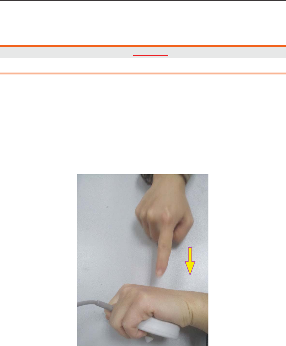
F Series Fetal & Maternal Monitor User Manual Fetal Monitoring
- 57 -
4 Select a value from 0 ~ 30 second(s) for Alarm Delay. (The step is 5, and the default
value is 10 seconds.)
5 Select OK.
WARNING
The FHR alarm delay is adjustable between 0 and 30 seconds.
7.2.6 Testing US Transducers
To test a US transducer:
1) Switch on the monitor.
2) Connect the US transducer to the fetal monitor.
3) Hold the transducer with one hand, and gently touch the center of the transducer
with the other hand in the frequency of 2 times per second.
Figure 7-2 Testing a US Transducer
4) Check that the value on the display shows this change in FHR.
If a US transducer fails the test, repeat this test with another transducer. If the second one passes
the test, defect of the first transducer is confirmed. Replace it with a good one. If the second
transducer fails the test as well, contact the manufacturer for service.
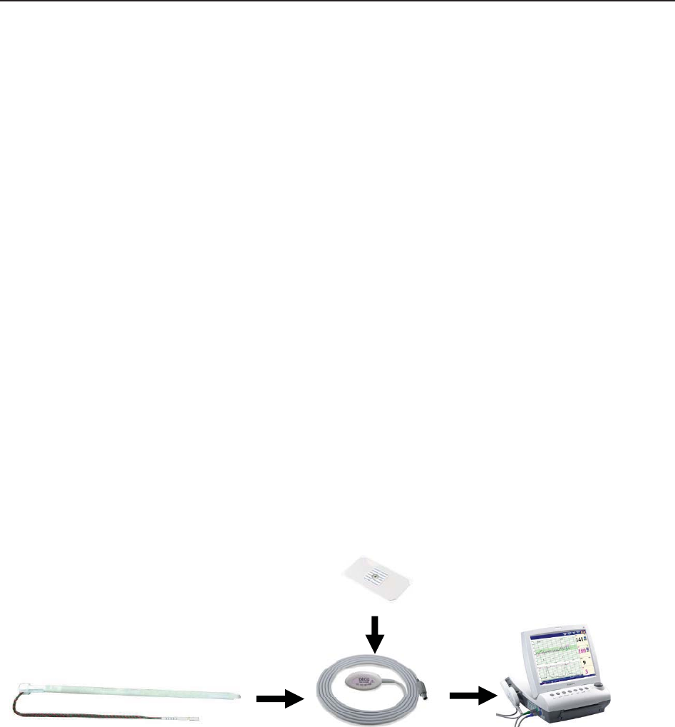
F Series Fetal & Maternal Monitor User Manual Fetal Monitoring
- 58 -
7.3 Monitoring FHR with DECG
7.3.1 Contraindications
The fetal spiral electrode can be used when amniotic membranes are adequately ruptured and
sufficient cervical dilatation is ensured. The fetal electrode tip is designed to penetrate the
epidermis of the fetus; therefore, trauma, hemorrhage and/or infection can occur. The electrode
should be used with strict adherence to aseptic technique.
The fetal spiral electrode should not be applied to the fetal face, fontanels or genitalia.
Do not apply the fetal spiral electrode when placenta previa is present; when the mother has
visible genital herpes lesions or reports symptoms of prodromal lesions; when the mother is HIV
sero-positive; when mother is a confirmed carrier of hemophilia and the fetus is affected or of
unknown status; or when it is not possible to identify fetal presenting part where application is
being considered. This method is not recommended when fetus is extremely premature, or in the
presence of a maternal infection such as Hepatitis B, Group B hemolytic strep, syphilis or
gonorrhea, unless a clear benefit to the fetus or mother can be established.
7.3.2 Parts Required
1) DECG cable 2) Fetal spiral electrode 3) Disposable attachment pad electrode
The following illustration shows how these parts should be connected:
Figure 7-3 Connection for DECG Monitoring
7.3.3 Preparing Patient's Skin Prior to Placing Electrodes
The skin is a poor conductor of electricity; therefore preparation of the patient's skin is important
to facilitate good electrode contact to skin.
1) Shave hair from electrode sites, if necessary.
2) Wash the sites thoroughly with soap and water. (Do not use ether or pure alcohol, which will
increase skin impedance)
3) Rub the skin briskly to increase capillary blood flow in the tissues.
(3)
(
2
)
(
1
)

F Series Fetal & Maternal Monitor User Manual Fetal Monitoring
- 59 -
4) Remove skin scurf and grease.
7.3.4 Changing DECG Beep Volume
When the DECG beep is enabled, the monitor gives a beep sound of DECG.
To change the DECG beep volume,
1 Select the setup key on the main interface.
2 Select Fetus > DECG Beep.
3 Select 0(default) ~ 9.
4 Select OK.
NOTE:
1 The DECG beep and HR beep share the same audio channel. Once the DECG beep
is switched on, the HR beep is disabled (set to level 0) automatically.
2 Once the DECG/HR beep volume is changed, the sound switches to channel 1
automatically. Therefore, it is advised against changing DECG/HR beep volume in the
monitoring process.
7.3.5 Switching the Artifact Suppression On or Off
When monitoring FHR with DECG, artifacts may occur due to bad connection of the spiral
electrode, excessive motion of the mother, electromyographic interference etc.. The Artifact
Suppression feature is designed to eliminate the interference. When artifact suppression is on,
artifacts are suppressed and not recorded. When it is off, the artifacts are shown as well as the
fetal heartbeats.
You can choose to switch the artifact suppression on or off.
1 Select the setup key on the main interface.
2 Select Fetus > Artifact Suppression.
3 Select ON (default) or OFF.
4 Select OK.
WARNING
When artifact suppression is on, fetal arrhythmia will also be suppressed. Therefore, if
fetal arrhythmia is suspected, switch artifact suppression off.

F Series Fetal & Maternal Monitor User Manual Fetal Monitoring
- 60 -
7.3.6 Directions for Using Fetal Spiral Electrode
1 With the patient in the dorsal lithotomy position, perform a vaginal examination and
clearly identify the fetal presenting part.
2 Remove the spiral electrode from the package; leave the electrode wires locked in the
handle notch.
3 Gently bend the guide tube to the desired angle.
4 Hold the drive handle, ensure the spiral electrode is retracted about one inch (2.5 cm)
from the distal end of the guide tube.
5 Place the guide tube firmly against the identified presenting part.
6 Maintain pressure against the fetal presenting part with guide and drive tubes. Rotate the
drive tube by rotating the drive handle clockwise until gentle resistance is encountered.
Resistance to further rotation and recoil of the drive handle indicates that the spiral
electrode is well attached to the fetus.
7 Release the electrode wires from the handle notch and straighten them. Slide the drive
and guide tubes off the electrode wires.
8 Insert the safety cap into DECG cable.
Figure 7-4 The well-attached fetal spiral electrode
7.3.7 DECG Monitoring Procedure
1 Perform a vaginal examination to identify the fetal presenting part.
2 Prepare the patient’s skin using the procedures described in section 7.3.3 Preparing
Patient's Skin Prior to Placing Electrodes.
3 Attach the fetal spiral electrode to the fetal presenting part using the procedures
described in section 7.3.6 Directions for Using Fetal Spiral Electrode.
4 Fix an attachment pad electrode to DECG cable.

F Series Fetal & Maternal Monitor User Manual Fetal Monitoring
- 61 -
5 Remove the film on the back of the electrode and place the electrode on maternal thigh;
press it firmly in place.
6 Connect the fetal spiral electrode to the DECG cable.
7 Insert connector of DECG cable into the DECG socket of the monitor.
WARNING
Do not plug the fetal spiral electrode wire into the power socket.
CAUTION
Do not mistake the higher maternal heart rate for DECG.
NOTE:
1 If there is any doubt as to the presence of a fetal heart signal with ECG, check with
the US transducer on the patient’s abdomen or with a separate diagnostic instrument.
The presence of an audible heart sound at a rate distinct from that of the maternal
pulse is unequivocal evidence of the fetal life.
2 After the electrode is well attached, allow a few minutes for the electrode and fetal
tissue to become stabilized. It is essential that the ECG signal electrode is in good
contact with the fetal presenting part.
7.3.8 Detaching Fetal Spiral Electrode
To detach the fetal spiral electrode, rotate it counterclockwise until it is free from the fetal
presenting part. Do not pull the electrode from the fetal skin forcefully.
Dispose of the used fetal spiral electrode in a proper way. Do not use it again.
7.4 Monitoring Twin FHRs
7.4.1 Monitoring Twins Externally
To monitor twin FHRs externally, you need to connect a US transducer to US1 socket and the
second US transducer to US2 socket of the monitor. Follow the instructions described in Section
7.2 Monitoring FHR with Ultrasound to acquire FHR signals for both channels. Press
CHANNEL key to switch the FH sound from one channel to the other.
When the two US transducers are fixed, make sure FH sounds from both channels are clear, two
FHR traces and two FHR numerics are displayed on the screen.
NOTE:
To ensure that both transducers stay at the optimum location, each transducer should be
fixed with a separate belt.

F Series Fetal & Maternal Monitor User Manual Fetal Monitoring
- 62 -
7.4.2 Monitoring Internally
Alternatively, you can monitor a FH using ultrasound externally, and monitor the second FH
using DECG internally.
Connect the US transducer to US2 socket; connect DECG cable to DECG socket.
Monitor one twin with a US transducer using the procedures described in Section 7.2 Monitoring
FHR with Ultrasound.
Monitor the other twin with a DECG cable using the procedures described in Section 7.3
Monitoring FHR with DECG.
CAUTION
The US transducer must be connected to US2 socket. If the US transducer connects to
US1 socket while DECG cable is connected to DECG socket, the FHR trace and
numeric from US1 will not be displayed.
7.4.3 Signals Overlap Verification (SOV)
When monitoring twins, there are possibilities that one twin’s FHR signal is mistaken for the
other one’s signal. The monitor provides signals overlap verification (SOV) function to reduce
these possibilities.
In the process of monitoring, if the SOV detects signals overlapping, an alarm message “Signals
Overlap (FHR1/DFHR, FHR2)” will appear on the screen to warn you. Checking the patient and
reposition of transducers might be needed.
7.4.4 Changing FHR2 Offset
In order to distinguish FHR1/DFHR trace from FHR2 trace, FHR2 offset is provided to help you
separate the two traces by an offset of -20 bpm or +20 bpm.
To change the FHR2/DECG offset,
1 Select the setup key on the main interface.
2 Select Recorder > FHR2 Offset.
3 Select -20 bpm (default), 0 bpm or +20bpm.
4 Select OK.
This preset FHR2 offset will be printed on the recorder paper every 10 minutes.

F Series Fetal & Maternal Monitor User Manual Fetal Monitoring
- 63 -
“FHR2: -20bpm”: the FHR2 trace is 20bpm lower than it really is.
“FHR2: 0bpm”: the FHR2 trace is in its real position.
“FHR2: 20bpm”: the FHR2 trace is 20bpm higher than it really is.
7.5 Monitoring Uterine Activity Externally
7.5.1 Parts Required
1) TOCO transducer 2) Belt
7.5.2 TOCO Monitoring Procedure
1) Placing Transducer Belt
Place the transducer belts across the bed, ensuring that the belt will be around the abdomen
when it is fastened. Lay the patient on the bed.
Alternatively, the patient can take a sitting position. Arrange the belt around her abdomen.
2) Fixing the Transducer
Wipe any gel remaining on abdomen around the fundus area.
Place the TOCO transducer on the patient’s abdomen, which is flat and approximately 3 cm
away from the fundus, e.g. slightly above the umbilicus on the left or on the right. The
position should be different for different purposes: place the transducer close to the fetal
buttocks for NST, and place it on fetal back in delivery.
Figure 7-5 Positioning TOCO Transducer
Wrap the abdomen with the belt over the transducer. Fix the transducer by pushing its buckle
through the overlapping section of the belt. Make sure the belt fits the patient snugly but
comfortably.
Place the transducer
on fetal buttocks for
NST
Place the transducer
on fetal back in
delivery

F Series Fetal & Maternal Monitor User Manual Fetal Monitoring
- 64 -
3) *Adjusting the Numeric to Zero
Press the AUTO ZERO key to adjust the numeric to the baseline. Make sure this is not done
during a contraction.
The uterine activity reading at this point should be 30 ~ 90. A flat-top aligned with 100 on
the TOCO scale indicates the belt is too tight, and you need to adjust it.
Wipe off any gel presents on abdomen around this area.
NOTE:
1 Do not apply aquasonic coupling gel on a TOCO transducer or its contact area.
2 Check the function of the TOCO transducer by applying pressure on it to see if this is
displayed on the screen.
7.5.3 Changing UA Baseline
You can change the UA baseline,
1 Select the setup key on the main interface.
2 Select Fetus > UA Baseline.
3 Select 5, 10 (default), 15 or 20.
4 Select OK.
NOTE:
If the monitor has been configured with IUP, the IUP baseline is 0 and it is not adjustable.
The TOCO baseline is adjustable.
7.5.4 Testing TOCO Transducers
To test a TOCO transducer:
1) Switch on the monitor.
2) Connect the TOCO transducer to the fetal monitor.
3) Gently press the center of the transducer.
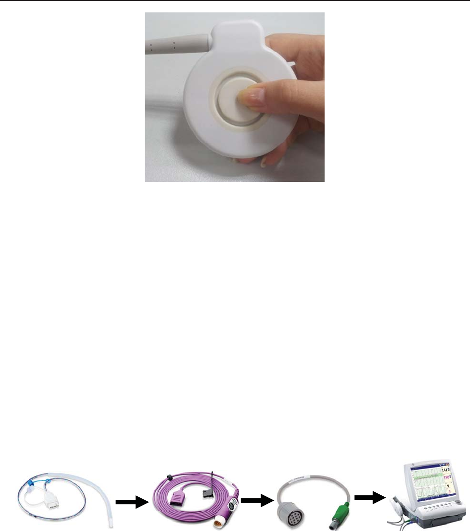
F Series Fetal & Maternal Monitor User Manual Fetal Monitoring
- 65 -
Figure 7-6 Testing a TOCO Transducer
4) Check that the value on the display shows this change in pressure.
If a TOCO transducer fails the test, repeat this test with another transducer. If the second one
passes the test, defect of the first transducer is confirmed. Replace it with a good one. If the
second transducer fails the test as well, contact the manufacturer for service.
7.6 Monitoring Uterine Activity Internally
7.6.1 Parts Required
1) Disposable intrauterine pressure catheter ACCU-TRACE™ IUPC (“IUPC” for short)
2) Reusable intrauterine pressure cable (“IUP cable” for short)
3) Reusable intrauterine pressure connecting cable (“connecting cable” for short)
The following illustration shows how these parts should be connected:
Figure 7-7 Connection for IUP Monitoring
7.6.2 Directions for Use of IUPC
Preparation
1) Gather supplies: ACCU-TRACE IUPC, reusable cable, and amnioinfusion supplies if
needed.
2) Open the sterile ACCU-TRACE IUPC package.
(
1
)
(
2
)
(
3
)

F Series Fetal & Maternal Monitor User Manual Fetal Monitoring
- 66 -
Insertion
NOTE:
This product is designed for use with the introducer.
3) Using aseptic technique, remove the catheter from the package.
4) Perform vaginal exam to ensure ruptured membranes and adequate dilation.
5) Advance the catheter tip to the cervical os along the examination hand, using the hand
as a guide. Do not advance the introducer through the cervix.
6) Continue to gently advance the catheter tip through the cervical os and feed the catheter
into the intra-amniotic cavity until the 45cm mark is at the introitus. If the 45cm mark is
not clearly visible, stop advancing when the symbol on the catheter meets the
introducer.
NOTE:
For easier insertion, do not twist the catheter in the introducer.
7) The IUPC may be spontaneously filled with amniotic fluid. This can be seen in the clear
lumen of the catheter. The filter cap will prevent the amniotic fluid from leaking.
8) Slide the introducer out of the vagina along the catheter. When the introducer is
completely out of the vagina, slide thumb between catheter and introducer tab, which
will begin to separate the introducer from the catheter.
Figure 7-8 Separate the introducer
9) Anchor the catheter in place with one hand, and pull the introducer straight back off the
catheter.
Figure 7-9 Remove the introducer
10) Remove the liner from the adhesive pad, and then adhere the pad to the patient’s skin.
Secure the catheter by placing the catheter attachment strap to the adhesive pad.
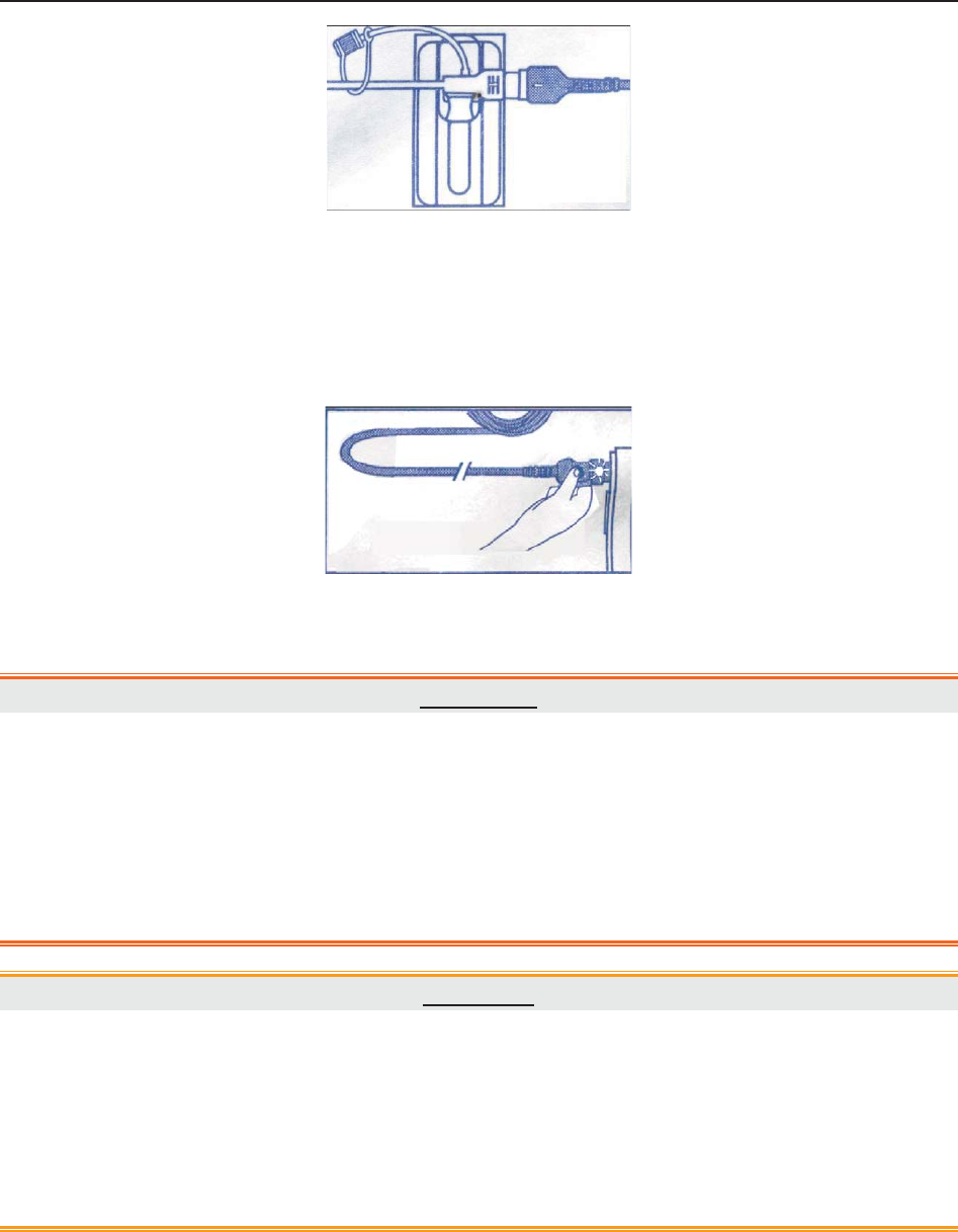
F Series Fetal & Maternal Monitor User Manual Fetal Monitoring
- 67 -
Figure 7-10 Secure the adhesive pad to mother
Rezeroing the System During Monitoring
1) With the catheter connected to the IUP cable, momentarily pressing the re-zero button
on the pressure cable. The green light on the cable will flash for five seconds.
Figure 7-11 Rezeroing the system
2) During this period, adjust the monitor to zero by pressing AUTO ZERO key.
WARNING
1 Before insertion of IUPC, placental position should be confirmed, amniotic
membranes are adequately ruptured and sufficient cervical dilatation is assured.
2 Try to insert the catheter opposite the placental site. Do not insert the introducer
beyond the cervical OS. Use it with caution when uterine infection is present.
3 If resistance is met at any time during insertion, withdraw the catheter slightly and try
at a different angle. Forced insertion may result in patient’s discomfort or injury.
CAUTION
1 Since procedures vary according to hospital needs/preferences, it is the responsibility
of the hospital staff to determine exact policies and procedures for both monitoring
and amnioinfusion. The safe and effective use of the IUPC depends on the skill of the
clinician who applies/uses it.
2 The Product has been sterilized by gamma radiation and is sterilized and
non-pyrogenic unless package is broken or open. Do not re-sterilize it.
NOTE:
Refer to the instruction on the package for more information about using the IUPC.
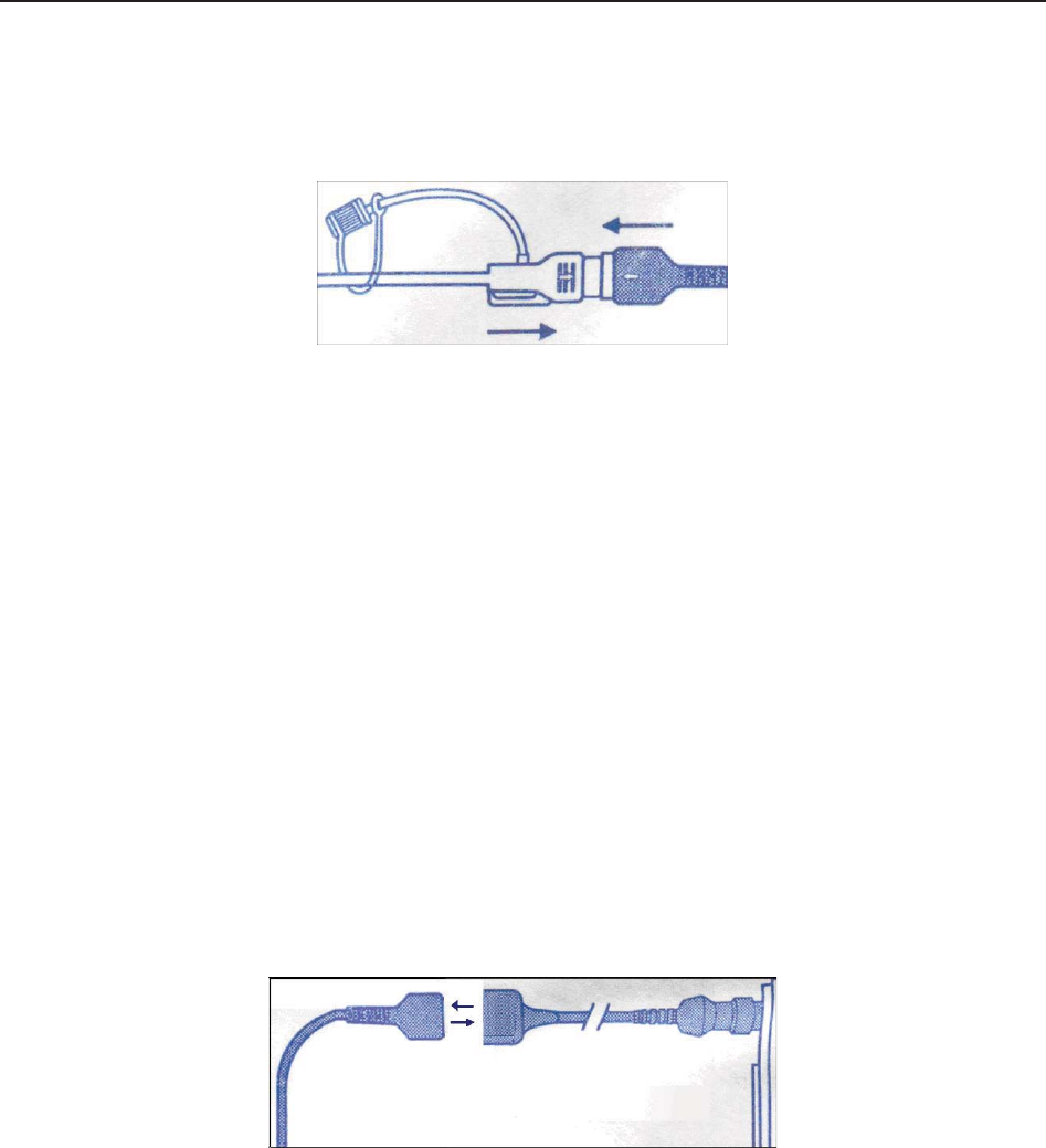
F Series Fetal & Maternal Monitor User Manual Fetal Monitoring
- 68 -
7.6.3 IUP Monitoring Procedure
1) Insert IUPC using the procedure described in section 7.6.2 Directions for Use of IUPC.
2) Connect the IUPC to the IUP cable.
Figure 7-12 Connect catheter to pressure cable
3) Connect the IUP cable to the connecting cable. (They might have already been well
connected in the package.)
4) Plug the connecting cable to the TOCO/IUP socket of the monitor.
5) Momentarily pressing the re-zero button on the IUP cable. The green light on the cable
will flash for five seconds. During this period, zero the monitor by pressing the AUTO
ZERO key. Make sure the display numeric and trace are both “0”.
6) Ask the mother to cough. A spike on the trace in response to the cough indicates proper
positioning and function of the IUPC.
7) Wash timely during monitoring. A spike on the tracing will respond to the washing.
7.6.4 Checking Intrauterine Pressure Cable Function
To test an IUP cable’s function:
1) Disconnect the catheter from the cable. Insert the cable check plug into the catheter end
of the cable.
Figure 7-13 Test the pressure cable
2) Verify that the green light is continuously lit (no flashing).
3) If the light does not illuminate, replace the cable.
NOTE:
1 If the light is flashing, verify that the cable check plug is inserted completely into the
cable.
2 The cable test function is not intended to check the accuracy of the system, only to
confirm cable function.

F Series Fetal & Maternal Monitor User Manual Fetal Monitoring
- 69 -
7.7 Monitoring Fetal Movement
7.7.1 Auto Fetal Movement (AFM) Monitoring
During fetal heart monitoring with ultrasound, the fetal movement signals are also detected. The
fetal movement signals differ from the Doppler heart rate signals in that they have larger extent
and lower frequency. The larger extent is because of the bigger scope of moving areas (e.g., the
fetal arms or legs); lower frequency is because of the lower velocity of the fetal movements
compared with those of the fetal heart.
Only US1 channel can perform AFM. But be aware that when monitoring twins, the movements
detected by US1 may also be caused by the second fetus’s movement.
The movement of the fetus will be detected and displayed in the form of a trace on the screen and
the recorder paper.
AFM monitoring can be switched off; its gain is adjustable.
NOTE:
AFM monitoring is not available when FHR is monitored by DECG.
7.7.2 Enabling or Disabling AFM Trace
The AFM trace on the screen and recorder paper can be enabled or disabled.
1 Select the setup key on the main interface.
2 Select Fetus > AFM.
3 Select ON or OFF (default).
4 Select OK.
7.7.3 Changing AFM Gain
You can change the AFM gain. The AFM gain affects overall numeric and scope of the AFM
trace.
1 Select the setup key on the main interface.
2 Select Fetus > AFM Gain.
3 Select 1, 2, 3 (default) or 4.
4 Select OK.

F Series Fetal & Maternal Monitor User Manual Fetal Monitoring
- 70 -
7.7.4 Choosing AFM Mode
When AFM monitoring is enabled, the AFM monitoring result is displayed either in the form of a
trace or black marks.
To choose AFM mode,
1 Select the setup key on the main interface.
2 Select Fetus > AFM Mode.
3 Select Trace (default) or Blackmark.
4 Select OK.
7.7.5 Choosing FM Source
When AFM monitoring is enabled, the FM has two sources: AFM and MFM.
To choose the FM source,
1 Select the setup key on the main interface.
2 Select Fetus > FM Source.
3 Select MFM (default) or AFM.
4 Select OK.
7.7.6 Manual Fetal Movement (MFM) Monitoring
MFM result comes from the patient’s feeling of fetal movement. The count will be displayed on
the screen in MFM numeric area.
1) Insert the FM marker connector into the MARK socket on the monitor.
2) Let the patient hold the marker in hand; ask her to press the top key of it when a fetal
movement is felt. Continuous movements in 5 seconds are considered to be one
movement and only press the key once.
7.7.7 Changing MFM Volume
The monitor gives a sound when the FM marker key is pressed, and the volume is adjustable.
To change the MFM volume,
1 Select the setup key on the main interface.
2 Select Fetus > MFM Volume.
3 Select Low or High (default).
4 Select OK.
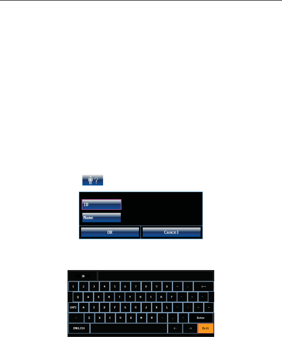
F Series Fetal & Maternal Monitor User Manual Fetal Monitoring
- 71 -
7.8 *Start Monitoring
After the START key is pressed, the monitor automatically zeroes the pressure, clears the MFM
count and starts monitoring.
If the Auto Printing is disabled, press the PRINT key to start printing.
7.9 *Inputting Maternal Information (Mat. Info)
7.9.1 Auto ID
After you press the START key, the system creates an auto-ID for the present patient. (if Mat.
Info inputting is switched off.) The auto-ID consists of the date and time when the monitoring
starts.
7.9.2 Changing Maternal Information
You can change the patient’s information after the monitoring starts:
1 Select Mat. Info key on the main interface.
Figure 7-14 Mat. Info Inputting Menu
2 Select ID.
Figure 7-15 Soft Keyboard
3 Select the required character for patient’s ID on the soft keyboard.
4 Select Enter.
5 Select Name.
6 Select the required letter for patient’s name on the soft keyboard.
7 Select Enter.
8 Select OK.

F Series Fetal & Maternal Monitor User Manual Fetal Monitoring
- 72 -
The monitoring does not stop when you change maternal information. After you select OK to exit,
the new ID takes the place of the old one for this patient.
NOTE:
1 Pressing the START key separates two patients. The monitor only displays the most
recent ID for the same patient.
2 If printing starts automatically with the monitoring, the first ID printed on the recorder
paper will be the auto-ID. The new ID will be printed 10 minutes later.
3 The ID and name are shown on the screen, the paper printout and the archive list.
4 For the non-English system, more letters are provided for inputting the name. Select
the key on the bottom left corner to toggle between them.
7.9.3 Switching Mat. Info Inputting On or Off
The Mat. Info inputting function allows the menu to pop up automatically after the START key
is pressed. After you input the mother’s information and exit from the menu, the monitoring starts
immediately.
To switch the Mat. Info Inputting on or off:
1 Select the setup key on the main interface.
2 Select Start Monitoring > Mat. Info.
3 Select ON or OFF (default).
4 Select OK.
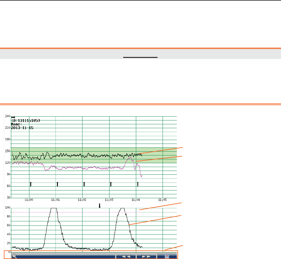
F Series Fetal & Maternal Monitor User Manual Fetal Monitoring Display
- 73 -
Chapter 8 Fetal Monitoring Display (F6/F9)
8.1 Traces
WARNING
1 Due to the LCD size, resolution and system settings, the traces displayed on the
screen may look different from the recorder printout. The printout should prevail
when making diagnoses.
2 If the data is doubtful, clinicians should make diagnoses based on the real condition.
Figure 8-1 Traces
During monitoring or reviewing, the trace window displays four traces: FHR1 trace, FHR2 trace
(dual configuration), AFM trace and TOCO trace.
FHR1/FHR2 trace
The y-axis of the trace indicates the numerics of FHR. The range is 30 bpm ~ 240 bpm
(American standard) or 50 bpm ~ 210 bpm (International standard).
AFM trace
The y-axis indicates the scope of fetal movement.
NOTE:
AFM trace is only for reference, please take the MFM marks as criterion.
1 FHR1 Trace
2 FHR2 Trace
3 AFM Trace
4 TOCO Trace
5 Trace Control Tools
1
2
3
4
5
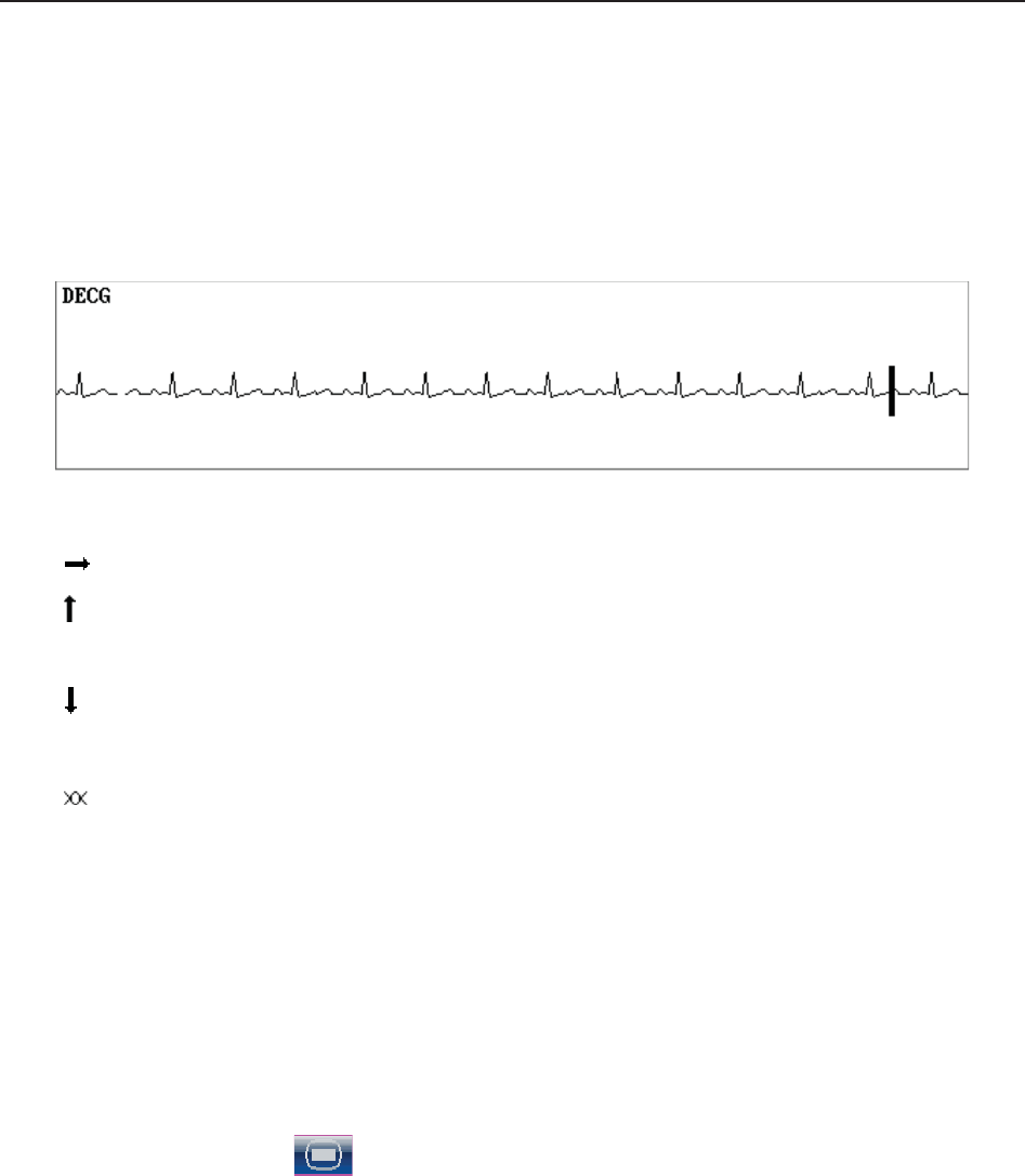
F Series Fetal & Maternal Monitor User Manual Fetal Monitoring Display
- 74 -
TOCO trace
The y-axis indicates the numeric of TOCO. The range is 0% ~ 100%.
If FHR is monitored using DECG, and the DECG trace is switched on in the hardware setup (only
service engineers have access to it), a DECG trace is shown underneath other traces on the
screen.
Besides, some other symbols appear among the traces:
This symbol indicates the new monitoring starts.
This symbol indicates a manual fetal movement, and it appears after the patient
presses the FM marker when she feels a fetal movement.
This symbol indicates the MARK key is pressed to record an event, such as the
patient turning around, taking injection.
This symbol indicates the monitor is zeroed by pressing AUTO ZERO key.
8.1.1 Changing Time Scale
The fetal monitoring traces share the same time scale. This scale is either in real time format or
relative time format. Real time is the time of the monitor. Relative time records the elapsed time
for the current monitoring.
To change this time format:
1 Select the setup key on the main interface.
2 Select Date And Time > Time Scale.
3 Select Real Time (default) or Relative Time.
4 Select OK.
NOTE:
The real time contains only the hour and minute, but no second. As a result, the time
scale may correspond to the 0 ~ 59th second of the system time. Do not mistake the time
scale for the exact time.
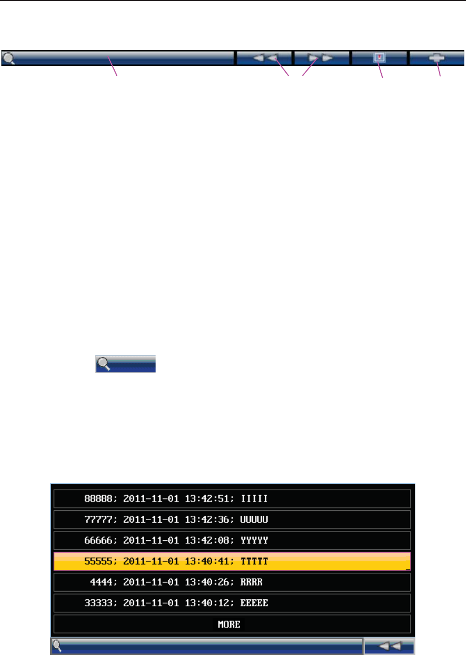
F Series Fetal & Maternal Monitor User Manual Fetal Monitoring Display
- 75 -
8.2 Trace Control Tools
1 2 3 4
Figure 8-2 Trace Control Tools
1 Searching Key 2 Reviewing Keys
3 Alarm Reviewing Key 4 CTG Analyzing Key
8.2.1 Data Saving
When the START key is pressed, the monitor saves data of the previous ID in a file, and then
clears it from the main interface. The main interface only displays the new patient’s data. During
monitoring, the data is saved every 10 minutes. All data of the same patient is saved in a file (the
maximum duration is 24 hours, the rest data is saved in another file.)
The files are stored in the monitor. When the data amount reaches the maximum capacity (300
files or approximately 60-hour), the monitor deletes the oldest file(s) automatically.
8.2.2 *Searching for a File
The searching key under the traces is used to search for a patient’s data file saved
in the monitor.
To search for a patient,
1 Select the searching key to open the file list. It contains six sets of most recent patient’s ID,
name and start time of monitoring. Select the required item, this file is loaded to the main
interface immediately.
Figure 8-3 File List
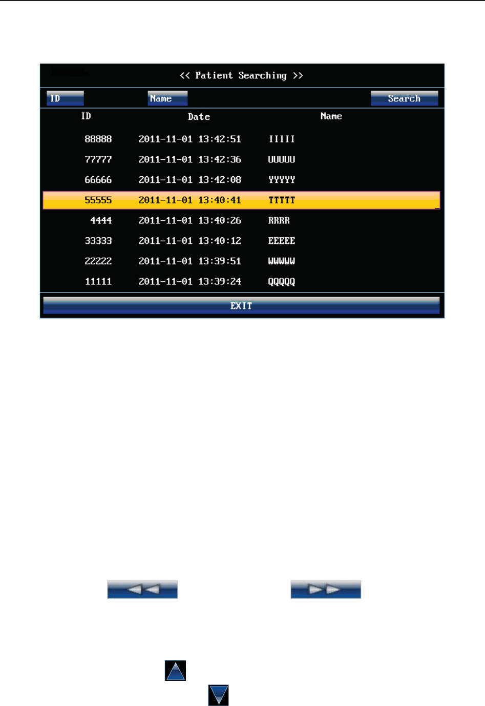
F Series Fetal & Maternal Monitor User Manual Fetal Monitoring Display
- 76 -
If the required file is not in this list,
2 Select MORE to open the Patient Searching window.
Figure 8-4 Patient Searching
3 Select ID, input the patient ID with the soft keyboard and select Enter.
4 Select Name, input the patient’s name with the soft keyboard and select Enter.
NOTE:
You can input only a part of the patient ID or name. However, the more information you
input, the more accurate result you will get.
5 Select Search. The files with the matched information are listed in the window.
6 Select the required item, this file is loaded to the main interface immediately. You can review
the traces backward or forward.
8.2.3 *Reviewing
The reviewing keys (backward key) and (forward key) are used
to review the traces. The word REVIEW is shown in the background when reviewing the traces.
Select the backward key to review the previous traces. The traces start to retreat. The amount of
the progress symbol “<” on top of the traces indicates the retreating speed. Rotate the control
knob anticlockwise or touch the symbol to increase the speed until it reaches the maximum.
Rotate the knob clockwise or touch the symbol to decrease the speed until it reaches the
minimum. Press the knob or touch any place on the screen to pause.
F Series Fetal & Maternal Monitor User Manual Fetal Monitoring Display
- 77 -
Select the forward key to review the next traces. The traces start to advance. The amount of the
progress symbol “>” on top of the traces indicates the advancing speed. Rotate the control knob
clockwise or touch the symbol to increase the speed until it reaches the maximum. Rotate
the knob anticlockwise or touch the symbol to decrease the speed until it reaches the
minimum. Press the knob or touch any place on the screen to pause.
When the reviewing is paused, the progress symbol turns to <--X%-->. If the PRINT key is
pressed at this moment, the recorder will print the traces starting from the left edge of the screen
at a high speed.
X% indicates the proportion of current traces positioned in the whole reviewable traces.
Move the cursor away from the trace control tools, or touch any place out of the trace window on
the screen to return to the real-time main interface. If no operation is performed in 10 seconds,
the monitor switches to real-time interface automatically, unless the printing is in process.
When reviewing the traces, the monitor does not stop. The FH sound and numerics are all real
time information of the current patient.
WARNING
The reviewing printout is provided for reference only. Please take the real-time printout
as criterion when making diagnoses.
NOTE:
1 The main interface only displays traces and patient information of one file. If you want
to review another file you should search for the file and load it.
2 For a real-time monitoring patient, you can print all her traces, including SpO2 trace.
However, when printing traces in a file, the SpO2 trace cannot be printed.
3 You must pause before printing starts. Printing in the process of playback might result
in failure information on the paper.
4 After the reviewed data has been printed out, the recorder does not switch back to
real-time printing automatically.
8.2.4 *CTG Analysis
CTG analysis aims at a real-time trace, providing some reference data for the physicians. It only
analyzes the real-time trace after it’s been printed for 10 minutes, and the longest duration is 60
minutes.

F Series Fetal & Maternal Monitor User Manual Fetal Monitoring Display
- 78 -
WARNING
1 CTG analysis is used for the surveillance of pregnancies and not in delivery room of
childbirth.
2 CTG analysis is just an analysis intended to assist the physicians in interpreting the
waveforms. Conclusions should be drawn on the basis of the physicians’ diagnosis.
3 This analysis describes the fetal heart rate, the tocography and the fetal movements.
It’s the responsibility of qualified medical staff to do the diagnostic interpretation of the
waveform.
8.2.4.1 Enabling/Disabling CTG analysis
1 Select the setup key on the main interface.
2 Select General Setup > CTG Analysis.
3 Select ON or OFF (default).
4 Select OK.
A CTG analysis key appears on the main interface, indicating that CTG analysis is
enabled.
8.2.4.2 CTG analyzing
NOTE:
1 CTG analyze starts after the real-time trace has been printed for 10 minutes.
2 The CTG analysis result is for reference only.
After the real-time trace is printed for 10 minutes, select the CTG analysis key on
the main interface. The analysis result window opens.

F Series Fetal & Maternal Monitor User Manual Fetal Monitoring Display
- 79 -
Figure 8-5 CTG Analysis Results
Refer to figure 8-5, the CTG analysis results on the screen include:
1) CTG Analysis Timer:
The CTG analysis timer starts when the recorder starts printing; it stops when the timer
reaches 60 minutes (the timer turns into >60) and resets when the recorder stops printing.
2) CTG Analysis Results:
SIGNAL LOSS: the proportion of the signal loss. If it is larger than 10%, analysis
results cannot be acquired.
CONTRACTIONS: the contraction time during analysis.
BASAL HEART
RATE:
the average FHR in 10 minutes when it is not influenced by fetal
movement or contractions.
ACCELERATIONS:
the acceleration time, including the acceleration with amplitude
larger than 10bpm and lasts more than 10 seconds, and the
acceleration with amplitude larger than 15bpm and lasts more than
15 seconds.
DECELERATIONS: the deceleration time.
SHORT TERM
VA R I AT I O N : the short-term variation analysis result.
LONG TERM
VA R I AT I O N : the long-term variation analysis result.
ANALYSIS START: the start time of the analysis.
ANALYSIS END: the finishing time of the analysis.
During 10 to 60-minute of the timer, the monitor gives CTG analysis results every minute.
1) CTG Analysis
Timer
2) Analysis Results

F Series Fetal & Maternal Monitor User Manual Fetal Monitoring Display
- 80 -
At the end of the printing, the recorder prints the CTG analysis results of this moment on the
recorder paper.
Be aware that CTG analysis result is a calculation output. It can be used as a reference to assist
medical personnel in making correct diagnosis, instead of replacing it.
NOTE:
Do not disconnect the ultrasound transducer(s) before the printing stops, otherwise the
analysis results will not be printed.
8.2.5 *Marking a Note
When there is a significant event, you can press the MARK key on the front panel to add a note.
An event mark will appear on both the main interface and the recorder paper.
However, an event mark cannot clearly indicate an event. Smart Notes provides a list of
annotation for the events, including events that relate to drugs, positions, membranes, procedures,
antenatal, reasons and others. This feature is only available on F9 and F9 Express.
8.2.5.1 Enabling/disabling Smart Notes
To enable or disable Smart Notes,
1 Select the setup key on the main interface.
2 Select General Setup > Smart Notes.
3 Select ON or OFF (default).
4 Select OK.
A smart note editing key appears next to the Smart Notes item.
8.2.5.2 Annotating an event
Once Smart Notes is enabled, press the MARK key on the front panel to open the smart note list,
choose an event catalog and then choose an annotation from the list.
The annotation of this event will be printed in the top area of recorder paper during real-time
printing.
8.2.5.3 Changing smart note content
You can change the smart note content in the smart note list by performing the following steps:
1 Select the setup key on the main interface.
2 Select General Setup.
3 Select the smart note editing key .
4 Select a catalog.
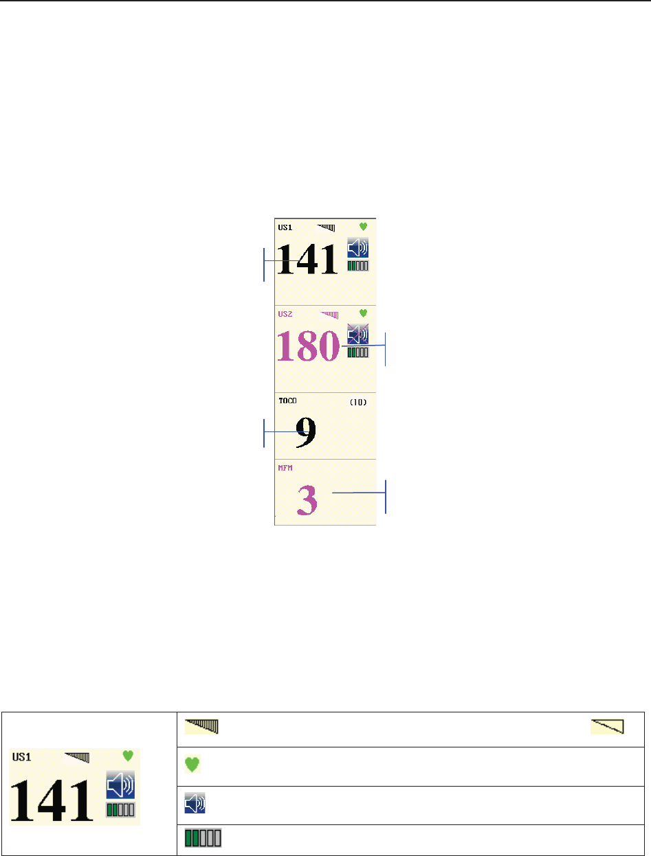
F Series Fetal & Maternal Monitor User Manual Fetal Monitoring Display
- 81 -
5 Select a note.
6 Use the soft keyboard to edit the note content.
7 Select Enter.
8 Select OK.
8.3 Numerics
Figure 8-6 Fetal Monitoring Numerics
The fetal monitoring values in the numeric window include FHR1/DFHR value, FHR2 value,
TOCO/IUP value and FM count:
FHR1/DFHR
: FHR signal quality. When the quality is poor, it turns into .
: FH refreshing rate
: FH sound volume adjusting key.
: FH sound volume indicator
FHR1
FHR2
TOCO
MFM

F Series Fetal & Maternal Monitor User Manual Fetal Monitoring Display
- 82 -
FHR2
141: FHR1/DFHR measurement numeric.
If the US1 socket is not connected with a US transducer and DECG
socket is not connected with a DECG cable, nothing displays here; if
the transducer/cable is connected but no monitoring is going on, it
displays ---.
180: FHR2 measurement numeric.
If the US2 socket is not connected with a US transducer when
switching on, it displays OFF but no numeric here; if the transducer is
connected but no monitoring is going on, it displays ---.
TOCO/IUP
(10)/(0): UA baseline
9: current UA measurement numeric
FM
MFM/AFM: FM source
3: FM count
When F9, F9 Express Fetal/Maternal Monitor is connected to FTS-3 Telemetry System, the
wireless US transducer and TOCO transducer signal strength and battery level are
displayed in the numeric window.
Figure 8-7

F Series Fetal & Maternal Monitor User Manual Fetal Monitoring Display
- 83 -
8.3.1 Changing Numeric Window Position (F9)
Especially for F9, the numeric window can be located either on the right of the traces or on top of
them. To change its position,
1 Select the setup key on the main interface.
2 Select General > Numeric Window.
3 Select Top or Right (default).
4 Select OK.
8.4 Fetal Monitoring Alarm Messages
During fetal monitoring, the monitor gives alarms for the situations that need the physicians to
pay attention to. The alarm messages are listed below.
8.4.1 Patient Alarm Messages
Alarm Message Source Cause Countermeasure
Medium Level
**FHR1 HIGH or
** FHR1 xxx > yyy,
**FHR2 HIGH or
** FHR2 xxx > yyy
US
FHR1 or FHR2 measuring
result (xxx) is higher than the
set upper limit (yyy) over the
alarm delay time. Check if the alarm limits are
suitable; check the patient’s
condition.
**FHR1 LOW or
** FHR1 xxx < yyy,
**FHR2 LOW or
** FHR2 xxx < yyy
US
FHR1 or FHR2 measuring
result (xxx) is lower than the
set lower limit (yyy) over the
alarm delay time.
8.4.2 Technical Alarm Messages
Alarm Message Source Cause Countermeasure
Medium Level
**Battery Low Monitor
The battery power is too low to
support further work of the
monitor.
Connect the monitor to AC
power supply.
Low Level

F Series Fetal & Maternal Monitor User Manual Fetal Monitoring Display
- 84 -
Check Paper Monitor There is no paper in the paper
drawer or the drawer is open.
Load paper and/ or close
the drawer.
US1 UNPLUGGED or
US2 UNPLUGGED US
US transducer 1 or US
transducer 2 is not well
connected.
Or wireless US signal is not
detected.
Check the connection of the
transducer.
US1 SIGNAL LOSS or
US2 SIGNAL LOSS US
FHR1 or FHR2 signal is too
weak for the system to
analyze.
Check if the US transducer
is aimed at the fetal heart;
check if the alarm limits are
suitable; check the patient’s
condition.
Fetus EQUIP MALF US
The fetus board can not
communicate with the system
successfully.
Restart the monitor and try
again, contact the
manufacturer if the
connection still fails.
TOCO UNPLUGGED TOCO
TOCO transducer is not well
connected.
Or wireless TOCO signal is not
detected.
Check the connection of
both TOCO transducer and
US transducer.
DECG LEADS OFF DECG The spiral electrode is not well
connected.
Check the connection of the
spiral electrode.
DECG UNPLUGGED DECG The DECG lead is not well
connected to the monitor.
Check the connection of the
DECG cable.
DECG SIGNAL LOSS DECG DECG signal is too weak for
the system to analyze.
Check if the spiral electrode
is well attached to the fetus;
check the patient’s
condition.
DECG EQUIP MALF DECG
The DECG board can not
communicate with the system
successfully.
Restart the monitor and try
again, contact the
manufacturer if the
connection still fails.
Signals Overlap
(FHR1, FHR2) US
US transducer 1 and US
transducer 2 are aimed at the
same fetal heart; the signals
overlap.
Adjust one of the US
transducers until another
fetal heart signal is
detected.
Signals Overlap
(DFHR, FHR2)
US +
DECG
US transducer 1 is aimed at
the fetus that the spiral
electrode is attached to; the
signals overlap.
Adjust the US transducer
until another fetal heart
signal is detected.

F Series Fetal & Maternal Monitor User Manual Maternal Monitoring
- 85 -
Chapter 9 Maternal Monitoring (F6 Express/F9 Express)
WARNING
1 Do not apply the monitor during electro-surgery or MRI; otherwise it might result in
harming the patient or the operator.
2 Always check if the alarm settings are appropriate for your patient before starting
monitoring.
3 Check for any fault of the transducers before applying them to the patient.
NOTE:
This feature is only available on F6 Express and F9 Express.
9.1 Maternal ECG Monitoring
9.1.1 Introduction
ECG monitoring produces a continuous wave form of the patient’s cardiac electric activity to
enable an accurate assessment of current physiological state. Only proper connection of ECG
cables can ensure a satisfactory measurement.
The parts needed are ECG lead and electrodes.
A 20-second monitor stabilization period shall be allowed before testing. The monitor has Tall
T-wave rejection capability.
The response time of heart rate meter to change in heart rate is less than 10s.
The minute heart rate display is updated at an interval of 1s.
Heart rate is computed by excluding the minimum and maximum values from the 12 most recent
RR intervals and averaging the residual 10 RR intervals. If each of three consecutive RR intervals
is greater than 1200ms, then the four most recent RR intervals are averaged to compute the HR.
The monitor does not have capability of detecting or rejecting pacemaker pulse, nor does it
provide a pulse to synchronize a defibrillator discharge.
The monitor does not give alarm for tachycardia and cardiac arrhythmia.
The d.c. offset voltage tolerance of the monitor is from -500mV to +500mV. If the d.c. offset
voltage of the detected ECG signal is out of this range, the monitor issues a high level alarm:
ECG SINGNAL EXCEEDS LIMIT.
WARNING
1 When connecting the cables and electrodes, make sure no conductive part is in
contact with the ground. Verify that all ECG electrodes, including neutral electrodes,
are securely attached to the patient.
2 The electrodes should be made of the same metal materials.
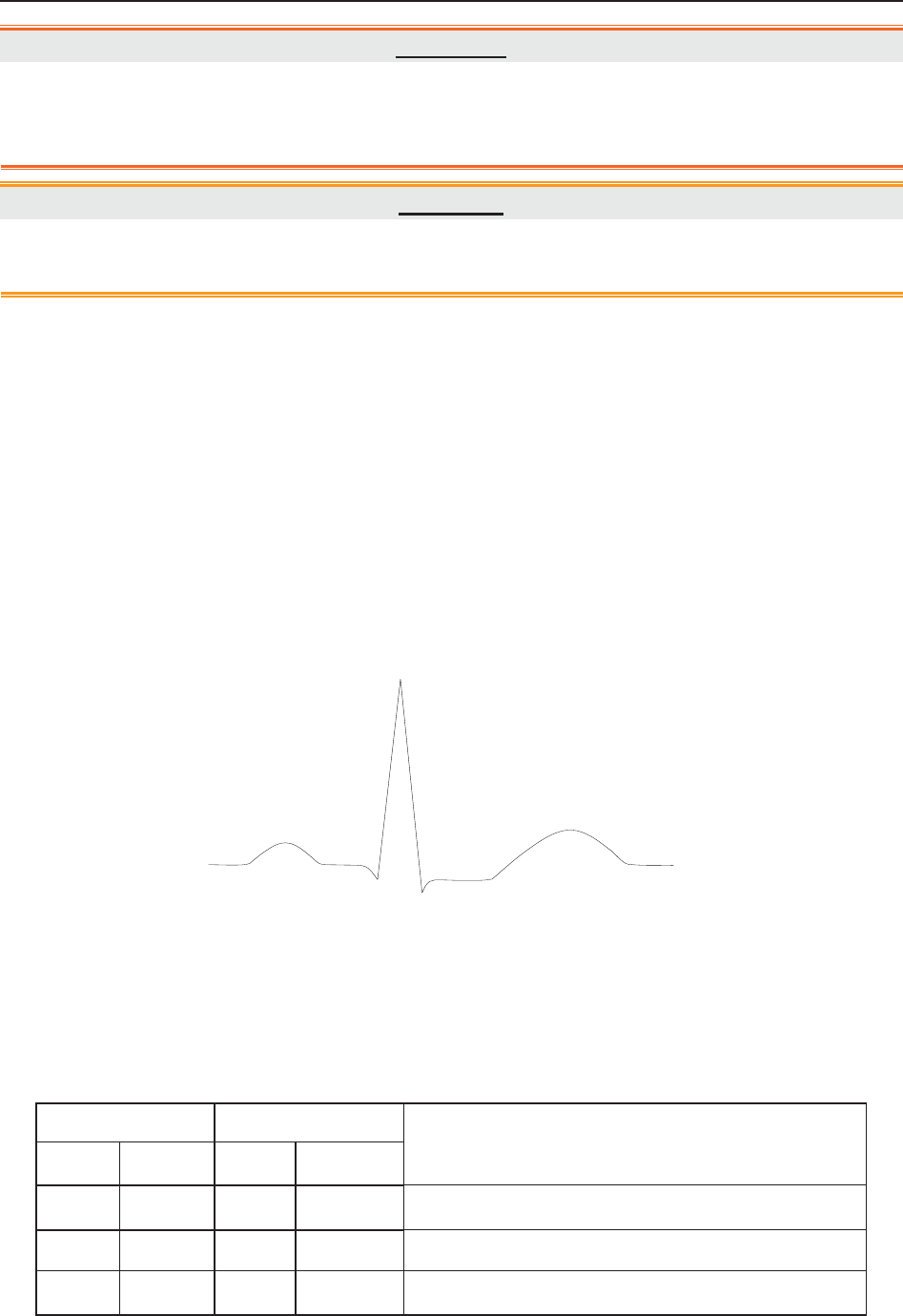
F Series Fetal & Maternal Monitor User Manual Maternal Monitoring
- 86 -
WARNING
3 ECG accessories are not suitable for DIRECT CARDIAC APPLICATION (Refer to
IEC60601-1 for more information about the definition of DIRECT CARDIAC
APPLICATION).
CAUTION
A different type of electrodes may produce higher offset voltage. Therefore, only use the
ECG leads supplied by the manufacturer when using the monitor for ECG monitoring.
NOTE:
Interference from a non-grounded instrument near the patient and ESU interference can
cause inaccuracy of the waveform.
A good ECG signal should be –
1) With normal QRS wave.
2) Tall and narrow with no notches.
3) With tall R-wave completely above the baseline.
4) With T-wave less than one-third of the R-wave height.
5) With P-wave much smaller than the T-wave.
Figure 9-1 Standard ECG Waveform
9.1.2 How to Place 3-lead ECG Cables
The table below lists the names and position of 3-lead ECG cable in America and Europe.
America Europe
Position
Name Color Name Color
RA White R Red Near the right shoulder, right below the clavicle
LA Black L Yellow Near the left shoulder, right below the clavicle
LL Red F Green On the left hypogastrium
R
P
Q
T
S

F Series Fetal & Maternal Monitor User Manual Maternal Monitoring
- 87 -
Figure 9-2 Placing 3-lead ECG Cable
NOTE:
1 To ensure patient’s safety, all leads must be attached to the patient.
2 Check everyday if the skin is irritated from ECG electrodes, if so, change for new
electrodes or change their sites every 24 hours.
3 Recycle or dispose the used electrodes properly to protect the environment.
9.1.3 ECG Monitoring Procedure
1) Prepare the skin for ECG monitoring. Refer to section 7.3.3 Preparing Patient's Skin Prior to
Placing Electrodes.
2) Insert the ECG cable connector into the MECG socket on the monitor.
3) Connect ECG electrodes with an ECG cable.
4) Peel the protection membrane off the back of ECG electrodes and attach electrodes to the
patient. Refer to section 9.1.2 How to Place 3-lead ECG Cables for electrodes’ sites.
NOTE:
After the monitor is switched on, if electrodes are not well attached or fell off, alarm
message “ECG LEADS OFF” will appear on the screen to draw your attention.
9.1.4 Changing ECG Source
Refer to figure 9-2, the ECG signal can come from channel I, II or III. In the ECG trace area of
the main interface, ECG (II, X1) indicates the ECG source and gain.
If the electrodes are tightly attached to the patient but ECG waveform is not accurate, switch
ECG source to another lead by performing the following procedures:
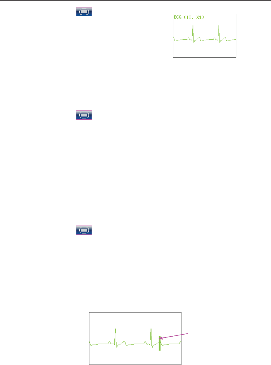
F Series Fetal & Maternal Monitor User Manual Maternal Monitoring
- 88 -
1 Select the setup key on the main interface.
2 Select Mother > Lead.
3 Select I, II (default) or III.
4 Select OK.
9.1.5 Changing ECG Gain
You can change the ECG gain. The ECG gain affects overall numeric and scope of the ECG
waveform.
1 Select the setup key on the main interface.
2 Select Mother > Gain.
3 Select X1/4, X1/2, X1 (default), X2 or Auto.
‘Auto’ means the monitor adjusts the gain automatically. The system displays a 1mv scale
at the left side of the ECG waveform. The height of 1mv bar is directly proportional to the
waveform amplitude.
4 Select OK.
9.1.6 Enabling ECG Calibration
When windage of the ECG waveform is suspected, enable ECG calibration to validate the wave.
1 Select the setup key on the main interface.
2 Select Mother > ECG Calibration.
3 Select Calibration or OFF (default).
4 Select OK.
The monitor creates a square wave in the ECG area. Compare the square wave with the ECG
gauge. If the error is larger than 0.5mm, change the ECG gain.
When the error is smaller than 0.5mm, calibration is completed. Disable ECG calibration in the
same directory.
ECG Gauge

F Series Fetal & Maternal Monitor User Manual Maternal Monitoring
- 89 -
9.2 Maternal SpO2 Monitoring
9.2.1 Introduction
The monitor provides continuous monitoring of functional arterial oxygen saturation (SpO2) and
pulse rate(PR) for pregnant women.
SpO2 Plethysmogram measurement is employed to determine the oxygen saturation of
hemoglobin in the arterial blood. If, for example, 97% hemoglobin molecules in the red blood
cells of the arterial blood combine with oxygen, then the blood has a SpO2 oxygen saturation of
97%. The SpO2 numeric on the monitor will read 97% .The SpO2 numeric shows the percentage
of hemoglobin molecules which have combined with oxygen molecules to form oxyhemoglobin.
The SpO2/PLETH parameter can also provide a pulse rate signal and a plethysmogram wave.
SpO2 Plethysmogram Measurement Principle:
Pulse oximetry is a continuous and noninvasive monitoring technique used to estimate the
measurement of arterial oxygen saturation. It measures the amount of light penetrating the
patient tissue and reaching the receiver. The reading, obtained through pulse oximetry, uses a
light sensor containing two sources of light (red and infrared) that are absorbed by
hemoglobin and transmitted through tissues to a photodetector.
The amount of light penetrated depends on multiple factors and most of them are constant.
However, the arterial blood flow changes with time passing by as is pulsative. The arterial
oxygen saturation can be obtained through testing the absorbed light during pulsation.
Plethysmogram wave and pulse rate signal can be also provided during pulsation testing.
The sensor contains LEDs that emit red light at a wavelength of approximately 660 nm and
infrared light at a wavelength of approximately 900 nm. Information about wavelength range can
be especially useful to clinicians.
The monitor is compatible with the SpO2 sensors supplied by the manufacturer only, and the
provided SpO2 sensor can only be used with this monitor.
Compatibility should be checked prior to use. Otherwise the monitor performance can be
degraded.
They have been tested and found to comply with the limits for medical device in
IEC/EN60601-1-2 (International standard for EMC testing of Medical Electrical Equipment,
second edition). These limits are designed to provide reasonable protection against harmful
interference in typical medical installation.
WARNING
1 Before monitoring, check whether the sensor cable is normal. If any sign of damage in
the SpO2 sensor is detected, do not use the sensor. Return it to the manufacturer for
service.
2 Do not put the SpO2 sensor on the extremities with arterial catheter or venous syringe.

F Series Fetal & Maternal Monitor User Manual Maternal Monitoring
- 90 -
WARNING
3 Do not perform SpO2 measuring and NIBP measuring on the same arm at one time,
because obstruction of blood flow during NIBP measuring may adversely affect the
reading of SpO2 numeric.
4 Prolonged and continuous monitoring may increase jeopardy of unexpected change
of dermal condition such as abnormal sensitivity, rubescence, vesicle, repressive
putrescence, and so on. It is especially important to check the sensor placement of
neonate and patient of poor perfusion or immature dermogram by light collimation and
proper attaching strictly according to changes of the skin.
5 The maximum application time of the SpO2 sensor at a single site is 4 hours. Check
the sensor placement every 2 to 3 hours and move it when the skin deteriorates.
More frequent examinations may be required for different patients.
6 Setting the SpO2 higher alarm limit to 100% is equivalent to switching off the alarm on
higher limit. High oxygen levels may predispose a premature infant to retrolental
fibroplasia. Therefore, the higher alarm limit for oxygen saturation must be carefully
selected in accordance with commonly accepted clinical practices.
CAUTION
Compatibility between the monitor and sensor should be verified before use to avoid
injuring the patient or operator.
NOTE:
1 The monitor is calibrated to display functional oxygen saturation.
2 A functional tester cannot be used to assess the accuracy of the SpO2 sensor or the
monitor.
3 The monitor does not have specific SpO2 calibration baselines.
4 SpO2 waveform is not proportional to the pulse volume.
5 Injected dyes such as methylene blue or intravascular dyshemoglobins such as
methemoglobin and carboxyhemoglobin may lead to inaccurate measurements.
Measurement Limits -
In operation, the accuracy of oximetry readings can be affected by:
1) Magnetic resonance imaging (MRI) scanning. Induced current could potentially cause burns.
2) Excessive patient movement.
3) Low perfusion.
4) High-frequency electrical noise, including noise created by the host system, or noise from
external sources, such as electrosurgical apparatus, which is admitted by the host system.

F Series Fetal & Maternal Monitor User Manual Maternal Monitoring
- 91 -
5) Intravascular dye injections.
6) Improper sensor application.
7) Sensor temperature. (Maintain the temperature between +28 °C (+82.4 °F) and +41 °C
(+105.8 °F) for best operation)
8) Placement of the sensor, such as on an extremity that has a NIBP cuff, arterial catheter, or
intravascular line.
9) Significant concentrations of dysfunctional hemoglobin, such as carboxyhemoglobin and
methemoglobin.
10) External illumination more than 5,000 lumens/square meter (typical office lighting). (Cover
the sensor site with opaque materials is recommended.)
11) Venous pulsations.
To use the sensor:
a) Select an appropriate sensor. Use an SpO2 sensors approved by the manufacturer.
b) Apply the sensor as directed, and observe all warnings and cautions presented in the sensor
user manual.
c) Clean and remove any substances, such as nail polish, from the application site.
d) Periodically check to ensure that the sensor remains properly positioned on the patient.
e) Cover the sensor site with opaque material.
9.2.2 SpO2 Monitoring Procedure
1) Insert the SpO2 sensor plug into the SpO2 socket on the monitor.
2) Place the forefinger, middle finger or third finger into the SpO2 sensor, refer to figure 9-3.
Figure 9-3 Placement of the Finger for SpO2 Measuring

F Series Fetal & Maternal Monitor User Manual Maternal Monitoring
- 92 -
NOTE:
1 The nail should cover the light but not too long.
2 The cable should be placed on the backside of the hand.
3 Avoid external light sources such as radiated rays or ultrared rays.
9.2.3 Enabling SpO2 Trace Printing
The real-time SpO2 measurement result is displayed in the parameter area of the main interface.
You can choose to print them as a continuous trace on the recorder paper (refer to figure 5-1).
To enable or disable SpO2 trace printing,
1 Select the setup key on the main interface.
2 Select Recorder > SpO2 Trace.
3 Select ON or OFF (default).
4 Select OK.
9.2.4 Assessing the Validity of a SpO2 Reading
You can check the quality of the pleth wave and the stability of the SpO2 values to assess
whether the sensor functions properly and whether the SpO2 readings are valid. Always use these
two indications simultaneously to assess the validity of a SpO2 reading.
NOTE:
1 The SpO2 accuracy has been validated in human studies against arterial blood
sample reference measured with a CO-oximeter. Pulse oximeter measurements are
statistically distributed, only about two-thirds of the measurements can be expected
to fall within the specified accuracy compared to CO-oximeter measurements. The
volunteer population in the studies composed of local healthy men and women from
age 19 to 37, with variations of skin pigmentations. The SpO2 accuracy is as follows:
±2% for 90%-100% and ±4% for 70%-90%.
2 The pulse rate accuracy is obtained by comparison to the pulse rate generated with
an arterial oxygen simulator (also an electronic pulse simulator).
3 Generally, the quality of the SpO2 pleth wave reflects the quality of the light signals
obtained by the sensor. A wave of poor quality manifests a decline of the signal
validity. On the other hand, the stability of the SpO2 values also reflects the signal
quality. Different from varying SpO2 readings caused by physiological factors,
unstable SpO2 readings are resulted from the sensor’s receiving signals with
interference. The problems mentioned above may be caused by patient movement,
wrong sensor placement or sensor malfunction. To obtain valid SpO2 readings, try to
limit patient movement, check the placement of the sensor, measure another site or
replace the sensor.

F Series Fetal & Maternal Monitor User Manual Maternal Monitoring
- 93 -
9.2.5 SI (Signal Intensity)*
*Only applicable to the EDAN module
The signal intensity (SI) shows perfusion in numeric, and it reflects the pulse intensity of the
measurement site. The SI ranges from 0 to 10, with a larger value indicating the more intense
signal. When the SI value reaches 10, the signal quality is optimal. If the SI value is less than 2, it
indicates that the pulse at the current site is weak, and you should change the measurement site.
The SI value is displayed in the SpO2 parameter area.
9.2.6 Switching the SpO2 Alarm On or Off
You can choose to switch the SpO2 alarm on or off.
1 Select the setup key on the main interface.
2 Select Alarm. On the displayed Password box, enter 9999, then select Enter.
3 Select SpO2.
4 Select ON (default) or OFF for Alarm.
5 Select OK.
9.2.7 Changing SpO2 Alarm Limits
You can change the SpO2 alarm limits.
1 Select the setup key on the main interface.
2 Select Alarm. On the displayed Password box, enter 9999, then select Enter.
3 Select SpO2.
4 Select a value from 50 ~ 99 for Low Alarm Limit. (The step is 1, and the default value is
90%.)
5 Select a value from 51 ~ 100 for High Alarm Limit. (The step is 1, and the default value is
100%.)
6 Select OK.

F Series Fetal & Maternal Monitor User Manual Maternal Monitoring
- 94 -
9.3 Maternal HR Monitoring
9.3.1 Introduction
Maternal heart rate (HR) monitoring does not need an extra accessory. When you perform ECG
or SpO2 (Pulse) monitoring, the HR result can be acquired at the same time.
When monitoring ECG and SpO2 at the same time, you can choose the HR source. If only one of
them is being performed, the source will automatically switch to the available one (the screen
reading should prevail).
9.3.2 Choosing HR Source
You can change the HR source.
1 Select the setup key on the main interface.
2 Select Mother > HR Source.
3 Select ECG (default) or Pulse (during SpO2 monitoring).
4 Select OK.
9.3.3 Changing HR Beep Volume
When the HR beep is enabled, the monitor gives a beep sound of maternal heart.
To change the HR beep volume,
1 Select the setup key on the main interface.
2 Select Mother > HR Beep.
3 Select OFF (default), Low or High.
4 Select OK.
NOTE:
1 The DECG beep and HR beep share the same audio channel. Once the HR beep is
switched on, the DECG beep is disabled (set to OFF) automatically.
2 Once the DECG/HR beep volume is changed, the sound switches to channel 1
automatically. Therefore, it is advised against changing DECG/HR beep volume in the
monitoring process.

F Series Fetal & Maternal Monitor User Manual Maternal Monitoring
- 95 -
9.3.4 Enabling HR Trace
The real-time HR measurement result is displayed in the parameter area of the main interface.
Also, you can choose to display and print those as a continuous trace on the recorder paper (refer
to figure 5-1).
To enable or disable HR trace printing,
1 Select the setup key on the main interface.
2 Select Recorder > HR Trace.
3 Select ON or OFF (default).
4 Select OK.
9.3.5 Switching the HR Alarm On or Off
You can choose to switch the HR alarm on or off.
1 Select the setup key on the main interface.
2 Select Alarm. On the displayed Password box, enter 9999, then select Enter.
3 Select HR.
4 Select ON (default) or OFF for Alarm.
5 Select OK.
9.3.6 Changing HR Alarm Limits
You can change the HR alarm limits.
1 Select the setup key on the main interface.
2 Select Alarm. On the displayed Password box, enter 9999, then select Enter.
3 Select HR.
4 Select a value from 30 ~ 239 for Low Alarm Limit. (The step is 1, and the default value is
50 bpm.)
5 Select a value from 31 ~ 240 for High Alarm Limit. (The step is 1, and the default value is
120 bpm.)
6 Select OK.
9.3.7 Signals Overlap Verification
When monitoring maternal heart rate and fetal heart rate at the same time, there are possibilities
that maternal HR signal is mistaken for FHR signal. The SOV function of the monitor can also
reduce these possibilities.

F Series Fetal & Maternal Monitor User Manual Maternal Monitoring
- 96 -
In the process of monitoring, if the SOV detects signals overlapping, an alarm message “Signals
Overlap (FHR1/FHR2, HR)” will appear on the screen to warn you. Checking the patient and
reposition of sensors might be needed.
9.4 Maternal NIBP Monitoring
9.4.1 Introduction
The monitor measures blood pressure using the oscillometric method.
Oscillometric devices measure the amplitude of pressure changes in the occluding cuff as the cuff
deflates from above systolic pressure. The amplitude suddenly increases as the pulse breaks
through the occlusion in the artery. As the cuff pressure decreases further, the pulsations increase
in amplitude, reach a maximum (which approximates to the mean pressure), and then diminish.
There are two modes available: Manual and Auto. In manual mode, NIBP is measured once on
each demand. In auto mode, NIBP is measured repeatedly after a preset time interval. This
interval is adjustable. You can perform a manual measurement during an Auto measurement
interval.
In both modes, systolic pressure (SYS) and diastolic pressure (DIA) are measured and displayed.
The blood pressure measurements determined with this device comply with the American
National Standard for Electronic or Automated Sphygmomanometers (ANSI/AAMI/ISO
81060-2:2009, ANSI/AAMI SP10:2002) in relation to mean error and standard deviation.
WARNING
1 Check for any fault of the cuff before start monitoring.
2 Do not perform NIBP measurements on patients with sickle-cell disease or under any
condition where the skin is damaged or expected to be damaged, such as on the arm
on the side of a mastectomy.
3 Pressurization of the cuff can temporarily cause loss of function of simultaneously
used monitor on the same limb.
4 If liquid is splashed on or into the main unit inadvertently, or enters the conduit, stop
using the monitor and contact the manufacturer for service immediately.
5 For a thrombasthemia patient, it is important to determine whether the measurement
of blood pressure shall be done automatically. The determination should be based on
clinical evaluation.
6 Do not apply the cuff to a limb that has an intravenous infusion or catheter in place
frequently. This could cause tissue damage around the catheter when infusion is
slowed or blocked during cuff inflation.
7 Make sure that the air conduit connecting the blood pressure cuff and the monitor is
neither blocked nor tangled.

F Series Fetal & Maternal Monitor User Manual Maternal Monitoring
- 97 -
NOTE:
The monitor is intended to measure NIBP for adults only.
Measurement Limitations -
To different patient conditions, the oscillometric measurement has certain limitations. The
measurement is in search of regular arterial pressure pulse. In those circumstances where the
patient's condition makes it difficult to detect, the measurement becomes unreliable and the
measuring time increases. You should be aware that the following conditions could interfere
with the measurement, making the measurement unreliable or longer to derive. In some cases,
the patient's condition will make a measurement impossible.
1) Patient Movement
Measurements will be unreliable or may not be possible if the patient is moving, shivering or
having convulsions. These motions may interfere with the detection of the arterial pressure
pulses. In addition, the measurement time will be prolonged.
2) Cardiac Arrhythmia
Measurements will be unreliable and may not be possible if the patient's cardiac arrhythmia
has caused an irregular heartbeat. The measuring time thus will be prolonged.
3) Heart-lung Machine
Measurements will not be possible if the patient is connected to a heart-lung machine.
4) Pressure Changes
Measurements will be unreliable and may not be possible if the patient's blood pressure is
changing rapidly over the period of time during which the arterial pressure pulses are being
analyzed to obtain the measurement.
5) Severe Shock
If the patient is in severe shock or hypothermia, measurements will be unreliable since reduced
blood flow to the peripheries will cause reduced pulsation of the arteries.
6) Heart Rate Extremes
Measurements can not be done to a patient whose heart rate is lower than 40 bpm or higher
than 240 bpm.
9.4.2 How to Apply NIBP Cuff
WARNING
Accuracy of NIBP measurement depends on using a cuff of the proper size. It is
essential to measure the circumference of the limb and choose the proper cuff size. If
you find something is wrong with the cuff size, please replace it immediately.
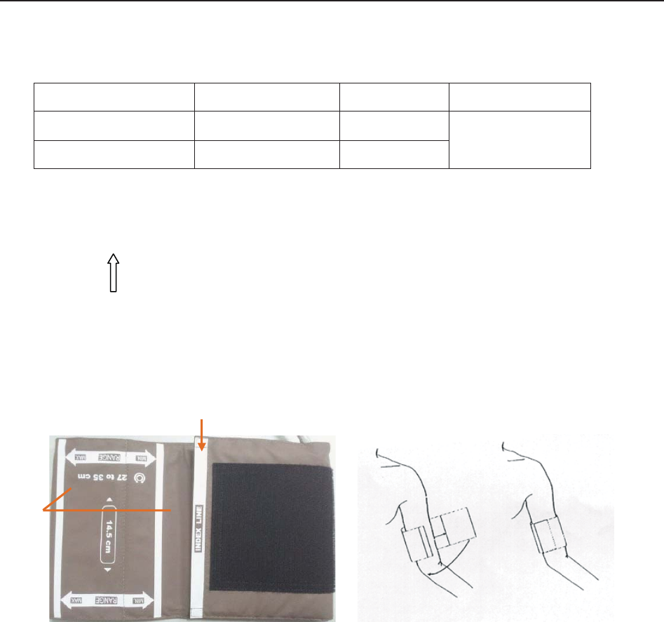
F Series Fetal & Maternal Monitor User Manual Maternal Monitoring
- 98 -
1) Select appropriate cuff for the patient.
The table below lists the reference size:
Type Limb Perimeter Cuff Size Air Hose Length
Upper Arm (Adult 1) 27 cm ~ 35 cm 14.5 cm 3 m
Upper Arm (Adult 2) 34 cm ~ 43 cm 18 cm
2) Squeeze the cuff to discharge the air.
3) Apply the cuff to the patient; make sure that the index line is placed in the appointed range and
the symbol is over the appropriate artery (Refer to figure 9-4). If the index line is not in the
appointed range, please replace for a proper one. Ensure that the cuff is not wrapped too
tightly around the limb. Excessive tightness may cause discoloration and eventual ischemia of
the extremities.
Figure 9-4: Applying the Cuff
9.4.3 Preparation for NIBP Monitoring
To obtain accurate measurements, the following operating steps need to be observed:
1. Ensure the patient position in normal use, including
comfortably seated
legs uncrossed
feet flat on the floor
back and arm supported
middle of the cuff at the level of the right atrium of the heart
2. Relax as much as possible and do not talk during the measurement.
Index Line
Appointed
Region
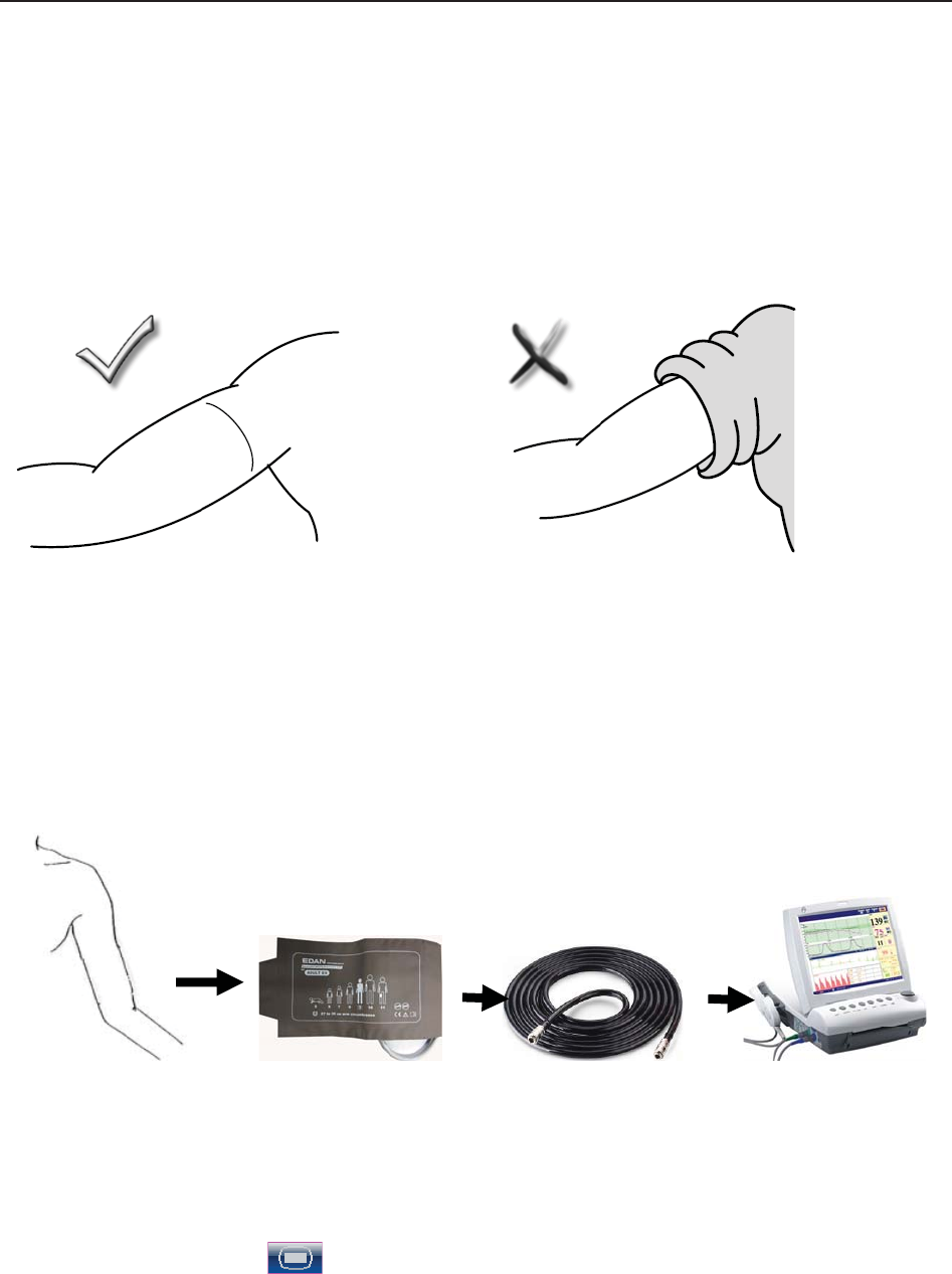
F Series Fetal & Maternal Monitor User Manual Maternal Monitoring
- 99 -
3. Wait for five minutes until the first reading is taken.
NOTES:
Please roll up the sleeve and keep the patient’s arm bare or it will cause the inaccurate
measurements.
1) Wrap the cuff on a bare arm.
2) Insert the cuff plug into NIBP socket on the monitor.
3) Apply the NIBP cuff to the patient’s arm or leg following the instructions described in section
9.4.2 How to Apply NIBP Cuff.
4) Connect the cuff to the air hose. The limb chosen for taking the measurement should be placed
at the same level as the patient's heart. If this is not possible, correct the measurement using
the formula described in section 9.4.6 Correcting the Measurement.
Figure 9-5 Connection for NIBP measurement
9.4.4 *Auto Measurement
To perform an auto measurement,
1 Select the setup key on the main interface.
2 Select Mother > Cycle.
3 Select a time interval from 1, 2, 3, 4, 5, 10, 15, 30, 60, 90, 120, 180, 240 and 480 minutes.
4 Select OK.

F Series Fetal & Maternal Monitor User Manual Maternal Monitoring
- 100 -
5 Press NIBP key on the front panel to start an Auto measurement.
NOTE:
The monitor checks uterine contract (UC) pressure when the NIBP key is pressed. If the
UC is over 50, a prompt “Intense UC, can't measure NIBP now.” is issued, and the
monitor will check the UC every 30 seconds. The monitor will measure NIBP only when
the UC is lower than 50, and it will then start timing for the Auto measurement.
To stop the current measurement,
Press the NIBP key anytime during the current measurement to stop it. Another measurement
will start after the time interval.
WARNING
Prolonged NIBP measurements in automatic mode may be associated with purplish
patches, ischemia and neurologic damage in the limb wearing the cuff. When monitoring
a patient, examine the extremities of the limb frequently for normal color, warmth and
sensitivity. If any abnormality is observed, stop the NIBP measurement.
9.4.5 *Manual Measurement
To perform a manual measurement,
1 Select the setup key on the main interface.
2 Select Mother > Cycle.
3 Select Manual.
4 Select OK.
5 Press NIBP key on the front panel to start a manual measurement.
To stop the manual measurement,
Press the NIBP key anytime during the measurement to stop it.
To perform a manual measurement during an auto measurement interval,
1 Press the NIBP key to start the manual measurement.
2 Press the NIBP key again anytime to stop it.
The monitor will restart timing for the Auto measurement and resume measuring after the time
interval.
NOTE:
1 If you are in doubt about the accuracy of any reading(s), check the patient's vital
signs by an alternative method before checking the functioning of the monitor.

F Series Fetal & Maternal Monitor User Manual Maternal Monitoring
- 101 -
2 The monitor checks uterine contract (UC) pressure when the NIBP key is pressed. If
the UC is over 50, a prompt “Intense UC, can't measure NIBP now.” is issued.
Please wait and do not attempt to measure NIBP until the UC is lower than 50.
CAUTION
1 Do not squeeze the rubber tube on the cuff.
2 If liquid is inadvertently splashed on the equipment or its accessories, or may enter
the conduit or inside the monitor, contact local service center.
9.4.6 Correcting the Measurement
To correct the measurement if the limb is not at heart level,
add 0.75 mmHg (0.10 kPa) for each inch higher.
deduct 0.75 mmHg (0.10 kPa) for each inch lower.
9.4.7 Changing NIBP Unit
You can change the NIBP unit.
1 Select the setup key on the main interface.
2 Select Mother > Unit (NIBP Setup).
3 Select mmHg (default) or kPa.
4 Select OK.
9.4.8 Switching the NIBP Alarm On or Off
You can choose to switch the NIBP alarm on or off. The SYS alarm and DIA alarm are related.
Once one of them is switched off, the rest will be switched off as well.
1 Select the setup key on the main interface.
2 Select Alarm. On the displayed Password box, enter 9999, then select Enter.
3 Select SYS or DIA.
4 Select ON (default) or OFF for Alarm.
5 Select OK.

F Series Fetal & Maternal Monitor User Manual Maternal Monitoring
- 102 -
9.4.9 Changing SYS Alarm Limits
You can change the SYS alarm limits.
1 Select the setup key on the main interface.
2 Select Alarm. On the displayed Password box, enter 9999, then select Enter.
3 Select SYS.
4 Select a value from 40 ~ 269 for Low Alarm Limit. (The step is 1, and the default value is
90 mmHg.)
5 Select a value from 41 ~ 270 for High Alarm Limit. (The step is 1, and the default value is
160 mmHg.)
6 Select OK.
9.4.10 Changing DIA Alarm Limits
You can change the DIA alarm limits.
1 Select the setup key on the main interface.
2 Select Alarm. On the displayed Password box, enter 9999, then select Enter.
3 Select DIA.
4 Select a value from 10 ~ 214 for Low Alarm Limit. (The step is 1, and the default value is
50 mmHg.)
5 Select a value from 11 ~ 215 for High Alarm Limit. (The step is 1, and the default value is
90 mmHg.)
6 Select OK.
9.4.11 *Choosing NIBP Printing Mode
When the recorder is printing real-time fetal traces, the NIBP result is also recorded on the paper
whenever NIBP measurement is performed. After the paper stops advancing, you can choose to
keep recording NIBP results on the paper.
To enable or disable NIBP printing after paper advancing stops,
1 Select the setup key on the main interface.
2 Select Recorder > NIBP.
3 Select ON or OFF (default).
4 Select OK.

F Series Fetal & Maternal Monitor User Manual Maternal Monitoring
- 103 -
NOTE:
The NIBP measurement results during the period of paper lacking and fast printing after
new paper is loaded will not be saved or printed. Therefore, do not perform NIBP
measurements during this period.
9.4.12 *Calibrating NIBP
NIBP is not user-calibrated. Cuff-pressure sensors must be verified and calibrated, if necessary, at
least once every two years by a qualified service professional.
9.5 Maternal TEMP Monitoring
9.5.1 TEMP Monitoring Procedure
1) Insert the TEMP plug into the TEMP socket on the monitor.
2) Apply the sensor firmly underneath the patient’s axilla. It takes 5 minutes for the temperature
measurement to stabilize.
WARNING
1 Check if the TEMP sensor functions properly prior to use.
2 Do not apply the TEMP sensor to the mouth or the rectum.
CAUTION
Be cautious when taking and putting the TEMP sensor. Do not pull the cable too tight or
it might cause mechanical damage.
The transient response time for the continuous TEMP sensor is not larger than 30s. The
laboratory method used to test the response time is as follows:
1. Prepare two reference temperature sources. The first one with a constant temperature of 25ºC
(77ºF) and the second one with a constant temperature of 27ºC (80.6ºF).
2. Put the TEMP sensor to the first reference temperature source until the temperature reading
reaches 25ºC (77ºF).
3. Move the TEMP sensor to the second reference temperature source. Note the time (t1) from
the TEMP sensor being moved in to the temperature reading reaching 27ºC (80.6ºF).
4. When the temperature reading is stable, move the TEMP sensor back to the first reference
temperature source. Note the time (t2) from the TEMP sensor being moved in to the
temperature reading falling to 25ºC (77ºF).
5. The larger value of t1 and t2 is the response time.

F Series Fetal & Maternal Monitor User Manual Maternal Monitoring
- 104 -
9.5.2 Changing TEMP Unit
You can change the TEMP unit.
1 Select the setup key on the main interface.
2 Select Mother > Unit (TEMP Setup).
3 Select ºC (default) or ºF.
4 Select OK.
9.5.3 Switching the TEMP Alarm On or Off
You can choose to switch the TEMP alarm on or off.
1 Select the setup key on the main interface.
2 Select Alarm. On the displayed Password box, enter 9999, then select Enter.
3 Select TEMP.
4 Select ON (default) or OFF for Alarm.
5 Select OK.
9.5.4 Changing TEMP Alarm Limits
You can change the TEMP alarm limits.
1 Select the setup key on the main interface.
2 Select Alarm. On the displayed Password box, enter 9999, then select Enter.
3 Select TEMP.
4 Select a value from 0.0 ~ 49.9 for Low Alarm Limit. (The step is 0.1, and the default
value is 36.0 ºC.)
5 Select a value from 0.1 ~ 50.0 for High Alarm Limit. (The step is 0.1, and the default
value is 39.0 ºC.)
6 Select OK.
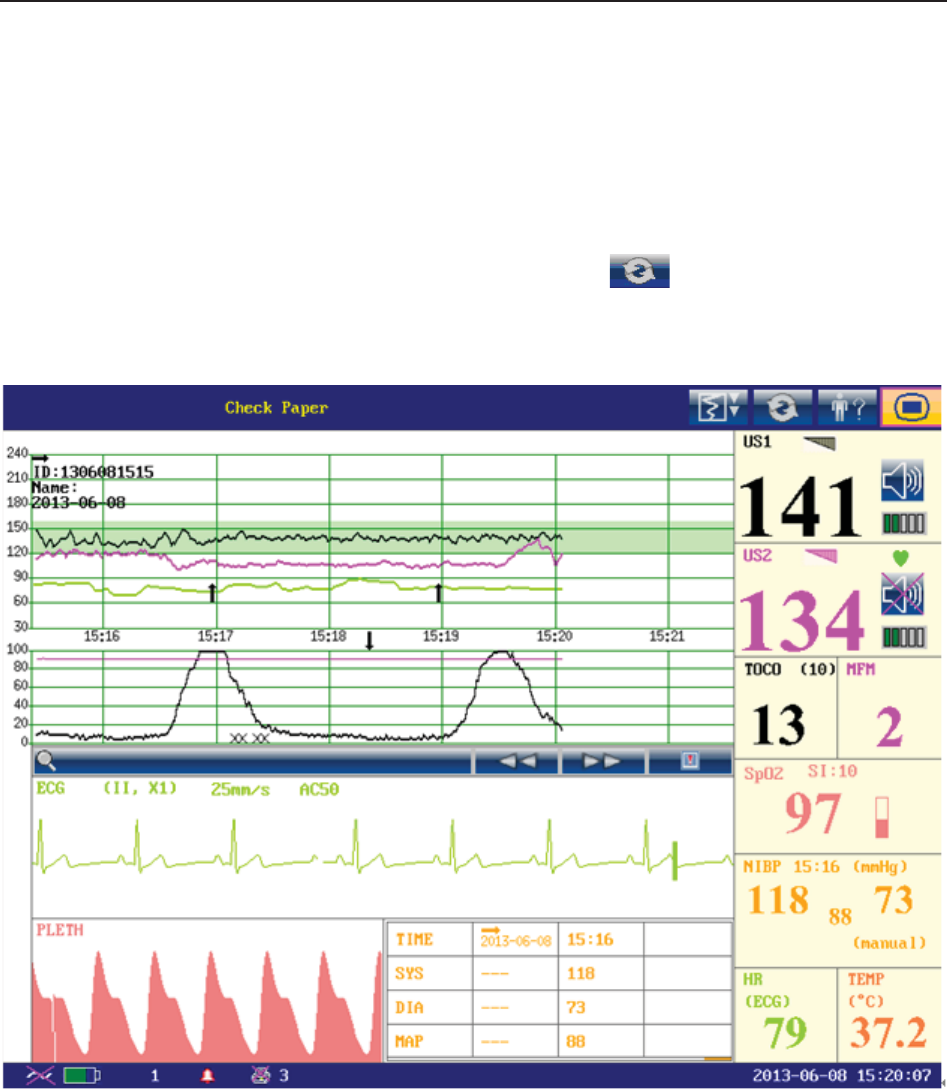
F Series Fetal & Maternal Monitor User Manual Maternal Monitoring Display
- 105 -
Chapter 10 Maternal Monitoring Display (F6 Express/F9 Express)
10.1 *Display Mode
F6 Express and F9 Express have three display modes: maternal-fetal display (figure 10-1), fetal
display (figure 10-2) and maternal display (figure 10-3).
To change the display mode, select the display mode switch on the main interface. The
display mode will switch among the three modes.
Figure 10-1 Maternal-Fetal Display mode
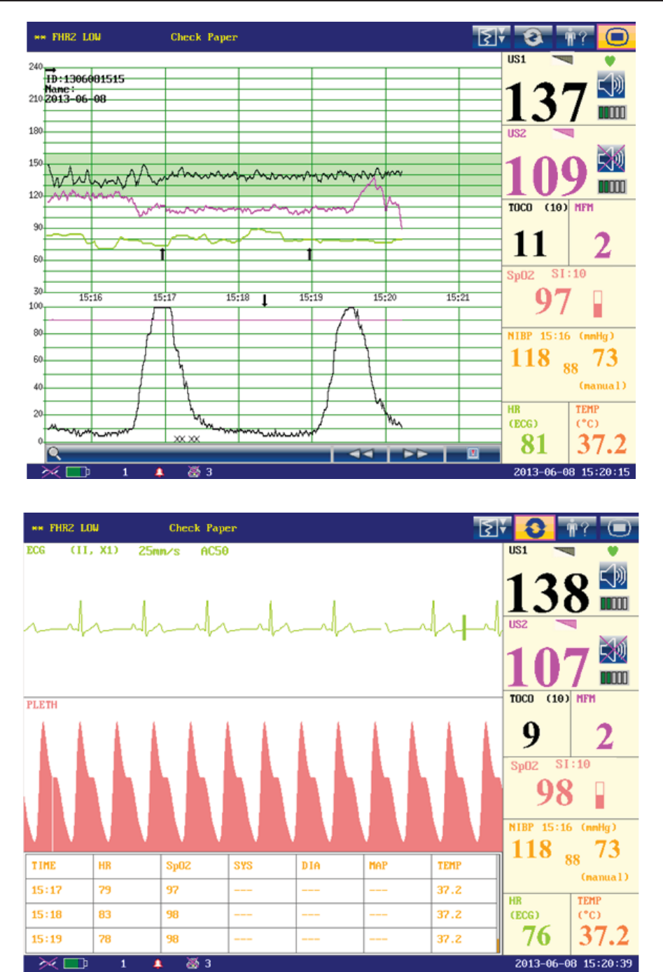
F Series Fetal & Maternal Monitor User Manual Maternal Monitoring Display
- 106 -
Figure 10-2 Fetal Display Mode
Figure 10-3 Maternal Display Mode
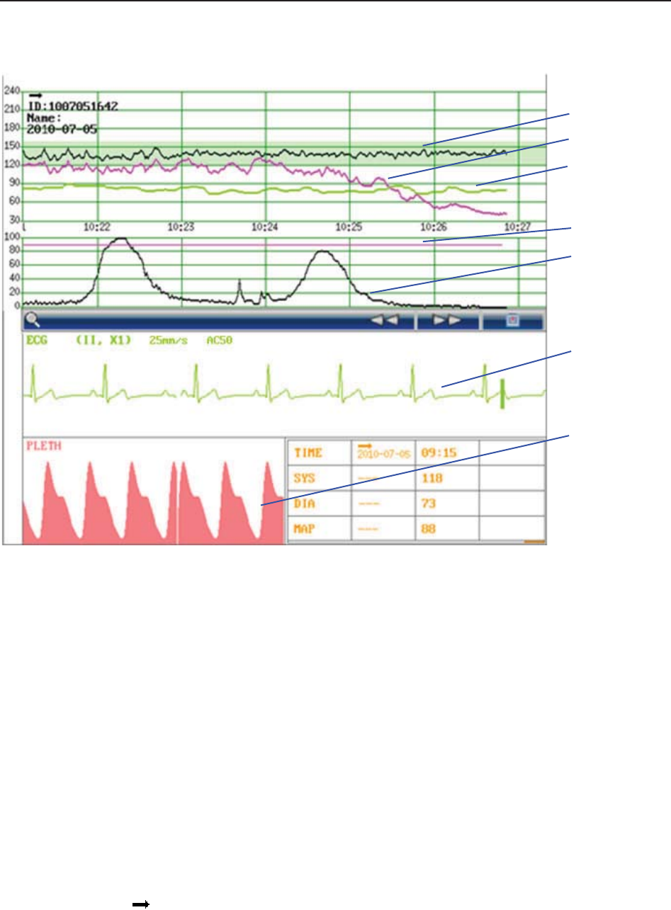
F Series Fetal & Maternal Monitor User Manual Maternal Monitoring Display
- 107 -
10.2 Maternal Monitoring Traces
Figure 10-4 Maternal Monitoring Traces
1 FHR1 Trace 2 FHR2 Trace 3 HR Trace 4 AFM Trace
5 TOCO Trace 6 ECG Trace 7 SpO2 Waveform
F6 Express and F9 Express display both maternal monitoring traces and fetal monitoring traces
on the same screen. The maternal monitoring traces include ECG waveform and SpO2 waveform.
The fetal monitoring traces are the same as traces of F6/F9, refer to 8.1 Fetal Monitoring Traces
for more information.
10.3 Maternal Vital Sign List
The maternal vital sign list keeps records of the recent maternal vital signs and the measuring
time. A start mark and the date appear when a new monitoring begins.
In maternal-fetal display mode, the list contains the time, SYS and DIA numerics of every
measurement.
1
2
3
4
5
6
7
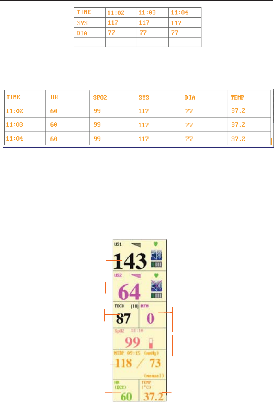
F Series Fetal & Maternal Monitor User Manual Maternal Monitoring Display
- 108 -
Figure 10-5 Maternal NIBP List
In maternal display mode, the list contains the time, HR, SpO2, SYS, DIA and TEMP numerics.
The numerics are recorded every minute.
Figure 10-6 Maternal Vital Sign List
The maternal vital sign list can be reviewed: select the list and then rotate the control knob to
review the previous lists.
10.4 Numerics
Besides the fetal numerics, the numeric window of F6 Express / F9 Express includes maternal
vital signs: SpO2, NIBP, HR and TEMP:
Figure 10-7 Numeric Window
FHR1
FHR2
TOCO
NIBP
HR
SpO2
TEMP
MFM
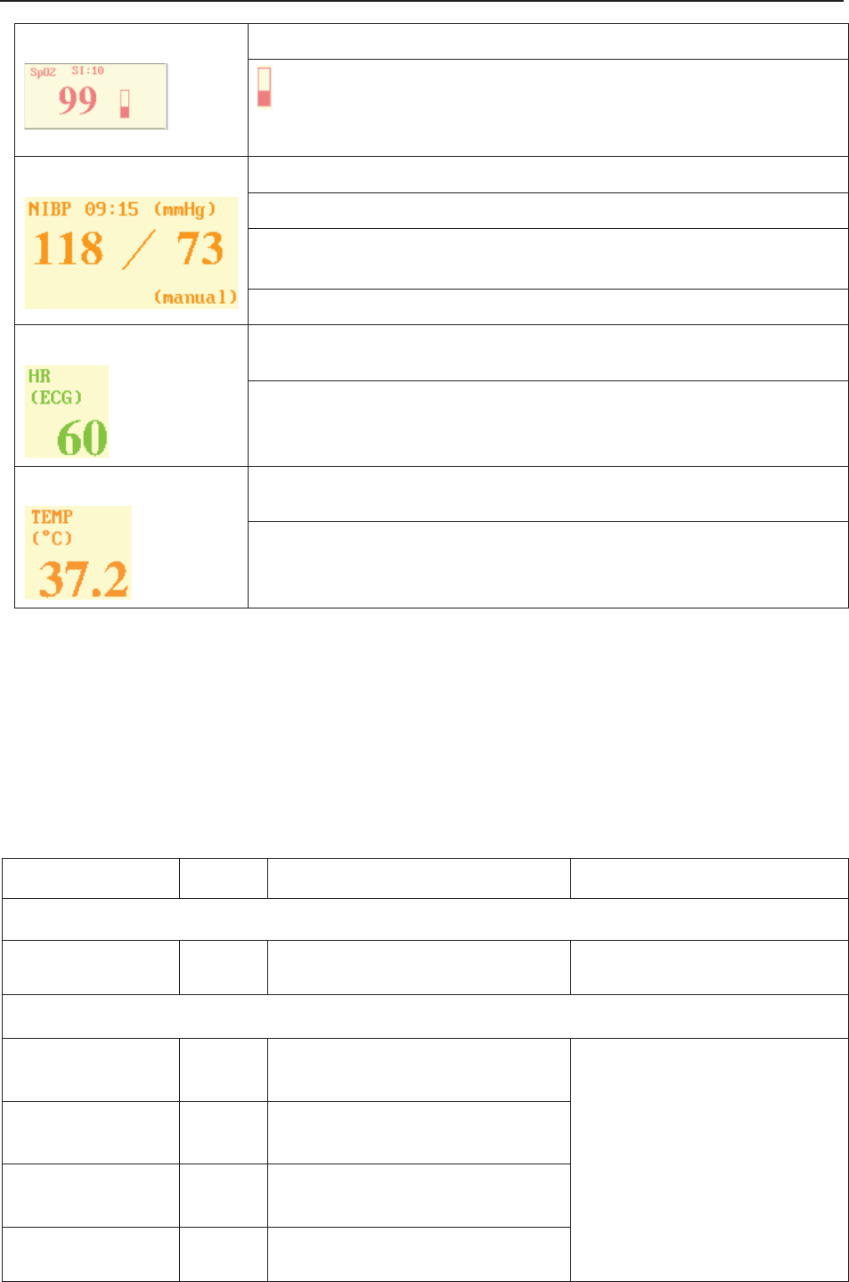
F Series Fetal & Maternal Monitor User Manual Maternal Monitoring Display
- 109 -
SpO299: Current SpO2 measurement numeric.
: SpO2 indicator.
SI: Signal intensity.
NIBP 09:15: Time when the NIBP measurement starts.
mmHg/kPa: NIBP unit.
From left to right in turn: systolic pressure (118) and diastolic pressure
(73).
(manual)/(Auto): The current NIBP measurement mode.
HR (ECG)/(Pulse): The current HR source.
60: Current maternal heart rate measurement numeric.
TEMP (ºC)/(ºF): TEMP unit.
37.2: Current TEMP measurement numeric.
10.5 Maternal Monitoring Alarm Messages
Besides the fetal monitoring alarms, F6 Express/F9 Express also gives alarms for the situations
that occur during maternal monitoring. The alarm messages are listed below.
10.5.1 Patient Alarm Messages
Alarm Message Source Cause Countermeasure
High Level
***ASYSTOLE ECG
No QRS wave is detected in 4
seconds
Check the patient’s condition
and take necessary measures.
Medium Level
**HR HIGH or
**HR xxx > yyy
ECG/
Pulse
Maternal HR result (xxx) is higher
than the upper limit (yyy).
Check if the alarm limits are
suitable; check the patient’s
condition.
**HR LOW or
**HR xxx < yyy
ECG/
Pulse
Maternal HR result (xxx) is lower
than the upper limit (yyy).
** SpO2 HIGH or
** SpO2 xxx > yyy SpO2 SpO2 result (xxx) is higher than
the upper limit (yyy).
** SpO2 LOW or
** SpO2 xxx < yyy SpO2 SpO2 result (xxx) is lower than the
upper limit (yyy).

F Series Fetal & Maternal Monitor User Manual Maternal Monitoring Display
- 110 -
**SYS HIGH or
**SYS xxx > yyy NIBP SYS result (xxx) is higher than the
upper limit (yyy).
Check if the alarm limits are
suitable; check the patient’s
condition.
**SYS LOW or
**SYS xxx < yyy NIBP SYS result (xxx) is lower than the
upper limit (yyy).
**DIA HIGH or
**DIA xxx > yyy NIBP DIA result (xxx) is higher than the
upper limit (yyy).
**DIA LOW or
**DIA xxx < yyy NIBP DIA result (xxx) is lower than the
upper limit (yyy).
**TEMP HIGH or
**TEMP xxx > yyy TEMP TEMP result (xxx) is higher than
the upper limit (yyy).
**TEMP LOW or
**TEMP xxx < yyy TEMP TEMP result (xxx) is lower than
the upper limit (yyy).
10.5.2 Technical Alarm Messages
Alarm Message Source Cause Countermeasure
High Level
***ECG SINGNAL
EXCEEDS LIMIT ECG ECG signal exceeds the
measurement limits.
Check the connection of the
leads and the patient’s
condition.
Low Level
Signals Overlap
(FHR1, HR)
US+ECG
/Pulse
US transducer 1 has picked up
the maternal heart signal; the
signals overlap.
Reposition the US transducer
1 until the fetal heart signal is
detected.
Signals Overlap
(FHR2, HR)
US+ECG
/Pulse
US transducer 2 has picked up
the maternal heart signal; the
signals overlap.
Reposition the US transducer
2 until the fetal heart signal is
detected.
Signals Overlap
(FHR1, FHR2,
HR)
US+ECG
/Pulse
US transducer 1 and US
transducer 2 have picked up the
maternal heart signal; the signals
overlap.
Reposition the US
transducers until the fetal
heart signals are detected.
ECG LEADS OFF ECG ECG leads are not well
connected.
Check the connection of
ECG leads.
ECG SIGNAL
LOSS ECG ECG signal is too weak for the
system to analyze.
Check if the ECG leads are
well attached; check the
patient’s condition.

F Series Fetal & Maternal Monitor User Manual Maternal Monitoring Display
- 111 -
ECG EQUIP
MALF ECG
The ECG board can not
communicate with the system
successfully.
Restart the monitor and try
again, contact the
manufacturer if the
connection still fails.
HR EXCEEDS
MEASUREMENT
RANGE
ECG/
Pulse
The heart rate exceeds the
measurement limits.
Check the connection of the
ECG leads/SpO2 sensor and
the patient’s condition.
NIBP EQUIP
MALF NIBP
The NIBP board can not
communicate with the system
successfully.
Restart the monitor and try
again, contact the
manufacturer if the
connection still fails.
NIBP SYSTEM
FAILURE NIBP The NIBP module defective.
Restart the monitor and try
again, contact the
manufacturer if the
connection still fails.
NIBP CUFF
LOOSE or OFF NIBP The cuff is loose or not
connected. Wrap the cuff properly.
NIBP OVER
PRESSURE NIBP The pressure has exceeded the
specified upper safety limit.
Measure again, if failure
persists, stop using the
monitor for NIBP measuring
and contact the manufacturer
for service.
NIBP CUFF TYPE
ERROR NIBP
A different cuff other than the one
supplied by the manufacturer is
used.
Use the cuff supplied by the
manufacturer.
NIBP LEAK NIBP The cuff, hose and (or) connector
are (is) damaged.
Check and replace the
leaking part(s). Contact the
manufacturer for service if
required.
NIBP SIGNAL
LOSS NIBP Cuff is too loose or the patient
pulse is too weak.
Use other methods to
measure NIBP.
NIBP SIGNAL
INTERFERED NIBP
Large signal noise or irregular
pulse rate caused by excessive
motions of the patient.
Keep the arm that is wrapped
with the cuff still.
NIBP EXCEEDS
MEASUREMENT
RANGE
NIBP The blood pressure exceeds the
measurement limits.
Check the connection of the
cuff and the patient’s
condition.
NIBP TIME OUT NIBP Measuring time has exceeded
120 seconds.
Start measuring again, or use
other measuring methods.
SpO2 LOW
PERFUSION SpO2
The signal received by SpO2
sensor is too weak, or the
measurement part has low
perfusion, and therefore the result
may be inaccurate.
Check the patient’s condition
and reposition the SpO2
sensor. Contact the
manufacturer for service if
the problem persists.

F Series Fetal & Maternal Monitor User Manual Maternal Monitoring Display
- 112 -
SpO2 SENSOR
OFF SpO2 SpO2 sensor is not well
connected.
Check the connection of
SpO2 sensor and finger
placement.
SpO2 EQUIP
MALF SpO2
The SpO2 board can not
communicate with the system
successfully.
Restart the monitor and try
again, contact the
manufacturer if the
connection still fails.
TEMP
UNPLUGGED TEMP TEMP sensor is not well
connected.
Check the connection of
TEMP sensor.
TEMP Calibration
Failed TEMP Calibration of the TEMP sensor
failed.
Restart the monitor and try
again. Contact the
manufacturer for service if
the problem persists.

F9, F9 Express Fetal & Maternal Monitor User Manual FTS-3 Fetal Telemetry System
- 113 -
Chapter 11 FTS-3 Fetal Telemetry System
11.1 Brief Introduction
FTS-3 Fetal Telemetry System (hereinafter called FTS-3) provides non-invasive monitoring for
the fetal heart rate (FHR) and testing TOCO for the pregnant women from the 28th week of
gestation. When connected to a compatible fetal monitor, FTS-3 provides wireless patient
monitoring in the antepartum period and during labor and delivery.
It is intended to be used only by trained and qualified personnel in antepartum examination rooms,
labor and delivery rooms. It is not intended for use in intensive care units, operating rooms or for
home use.
FTS-3 is used with F6, F9 series fetal/maternal monitor and connects to the monitor by signal
cable. The wireless transducers monitor the FHR, TOCO parameters within certain distance, and
then the base station sends them to the monitor through signal cable, and the monitor can display,
alarm, print or review the parameters.
FTS-3 consists of the wireless US transducers, the wireless TOCO transducer and the base
station.
The wireless signal can be transmitted in the Industrial Scientific Medical Band (ISM) according
to the local regulations. The transmission range depends on where the system is used. It is
recommended to use in hospital for better transmission. The transmission range is smaller in
water than that in the air.
Device FCC ID
Base Station SMQFTS3BEDAN
US Transducer SMQFTS3UEDAN
TOCO Transducer SMQFTS3TEDAN
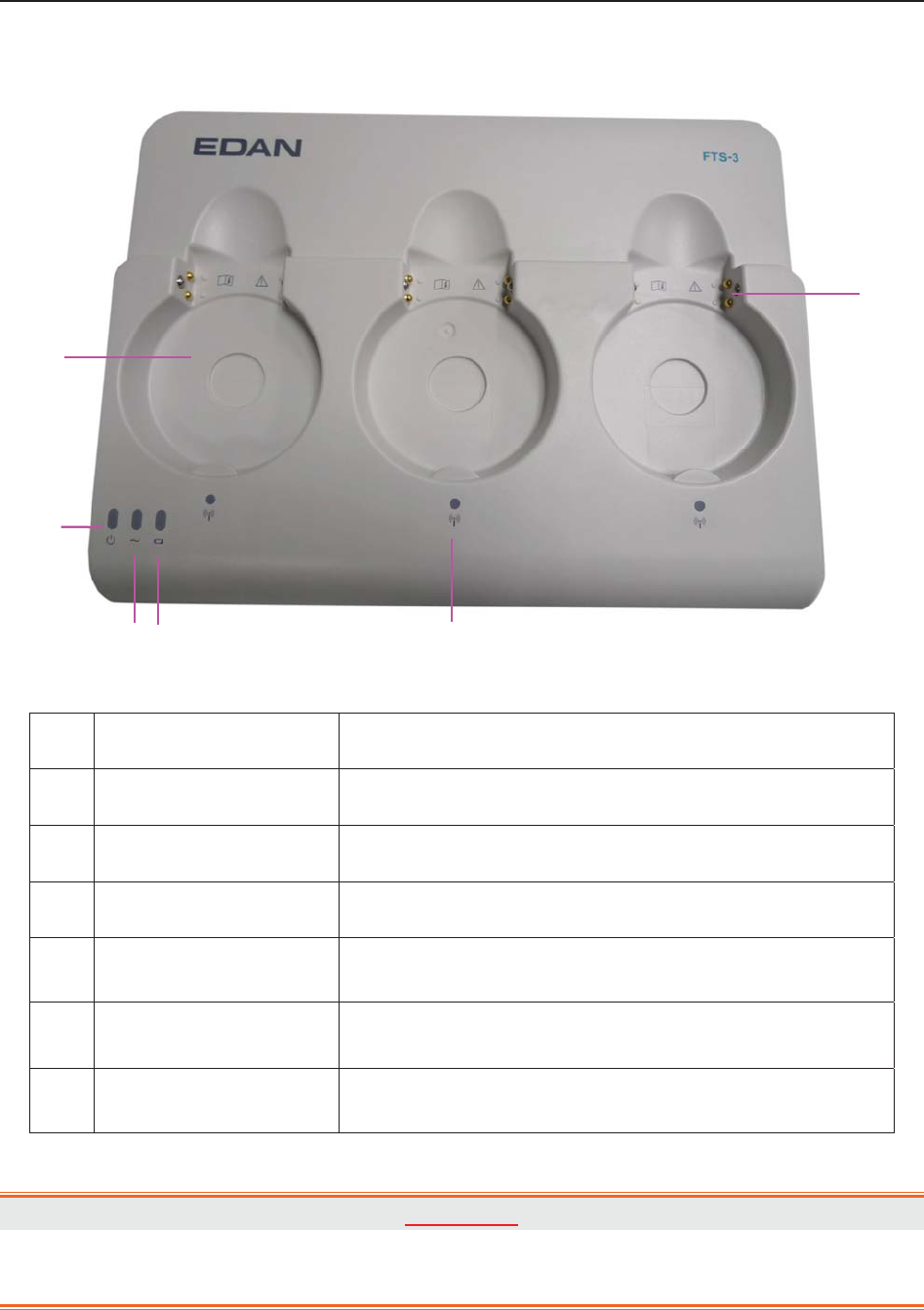
F9, F9 Express Fetal & Maternal Monitor User Manual FTS-3 Fetal Telemetry System
- 114 -
11.1.1 Base Station
Figure 2-1 Top Panel
Name Description
1 Docking Slot Place, charge and manage the transducer.
2 Power Indicator When you turn the power supply, the indicator is on.
3 AC Indicator When AC power is supplied, the indicator is on.
4 Battery Indicator When the base station battery is charging, the indicator
is on. When the battery is in low level, it is flashing.
5 Wireless Connection
Indicator
When the transducer connects to the base station
successfully, the green light is on.
6 Charging Point When you place the transducer in the docking slot, you
can charge the transducer by these points.
WARNING
The charging point is specially used for charging the medical equipment and please do
not touch the charging point and the patient at the same time.
1
2
3 4 5
6
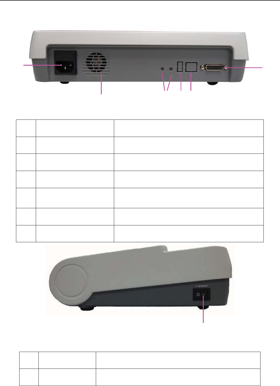
F9, F9 Express Fetal & Maternal Monitor User Manual FTS-3 Fetal Telemetry System
- 115 -
Figure 2-2 Rear Panel
Name Description
7 AC Outlet AC outlet.
8 Communication Socket Communicate to the bedside monitor.
9 Emission Slot Emit the heat.
10 Channel Adjustment
Button Adjust the channel.
11 USB port Reserved
12 Ethernet port Reserved
Figure 2-3 Right Panel
Name Description
13 Power Switch Turn on or turn off the base station.
13
7
9
8
10 11 12
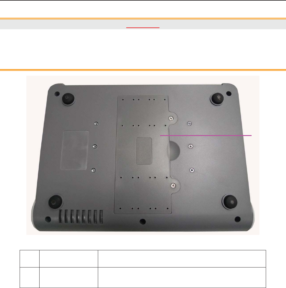
F9, F9 Express Fetal & Maternal Monitor User Manual FTS-3 Fetal Telemetry System
- 116 -
CAUTION
1. This monitor is a normal medical device. Please avoid violent operations such as
continuously pressing the power switch.
2. When the transducer is taken up, please do not power off the base station.
Figure 2-4 Bottom
Name Description
14 Battery
Compartment Install the battery.
14
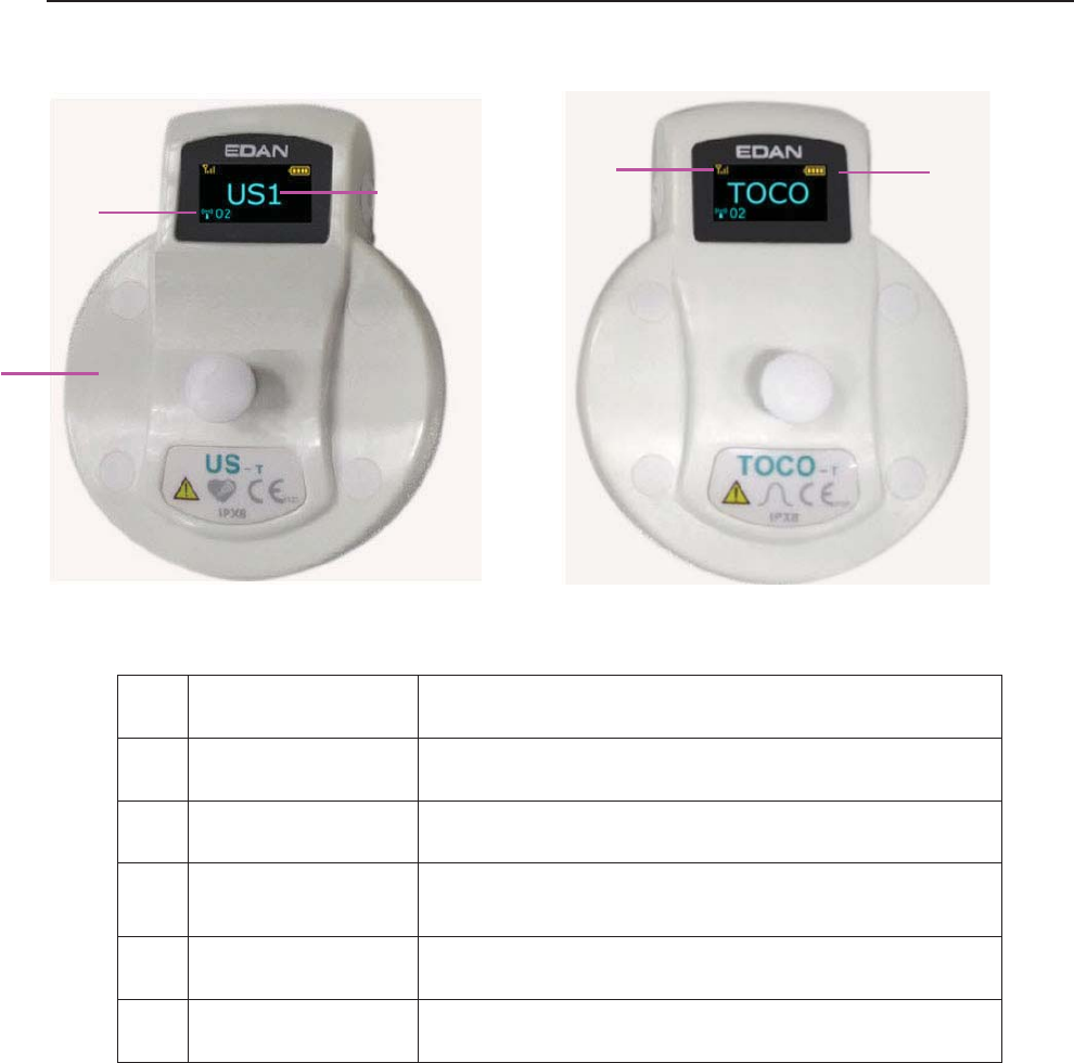
F9, F9 Express Fetal & Maternal Monitor User Manual FTS-3 Fetal Telemetry System
- 117 -
11.1.2 US Transducer and TOCO Transducer
US transducer TOCO transducer
Name Description
15 Transducer Tied to the pregnant women.
16 Transducer Type Indicate the transducer type.
17 System Working
Channel Indicate the system working channel.
18 Signal Indicator Indicate wireless signal strength.
19 Battery Indicator Indicate battery level.
11.1.3 Features
x Long work distance and free to walk in a great range
x Wireless transducers
x Low power consumption and working for long time
x Rechargeable transducers
x Cabinet, portable and waterproof transducers
x Provide rechargeable battery for base station
16
15
17
18 19

F9, F9 Express Fetal & Maternal Monitor User Manual FTS-3 Fetal Telemetry System
- 118 -
11.2 Installation Guide
WARNING
The system installation should be operated by serviceman authorized by the
manufacturer.
11.2.1 Opening the Package and Checking
Visually examine the package prior to unpacking. If any signs of mishandling or damage are
detected, contact the carrier to claim for damage.
Open the package; take out the base station and accessories carefully. Keep the package for
possible future transportation or storage. Check the components according to the packing list.
Check for any mechanical damage.
Check all the cables and accessories.
If there is any problem, contact us or your local distributor immediately.
11.2.2 Installing Battery
WARNING
Switch off FTS-3 and unplug it before installing or removing the battery.
NOTE:
1 If the system is provided with a rechargeable base station battery, please charge the
battery after each transportation and storage.
2 Please charge the battery to the full after each use. When the system is powered on
with the AC power supply, the battery is charging. Please do not interrupt the
charging and wait until the battery is fully charged.
If the system is provided with a rechargeable lithium-ion battery, follow these steps to install the
battery:
(1) Battery Installation
a) Place FTS-3 upside down on a flat surface covered with cloth or another type of protecting
pad.
b) Remove the screws of the battery compartment using a cross-head screw driver. Remove the
battery compartment cover.
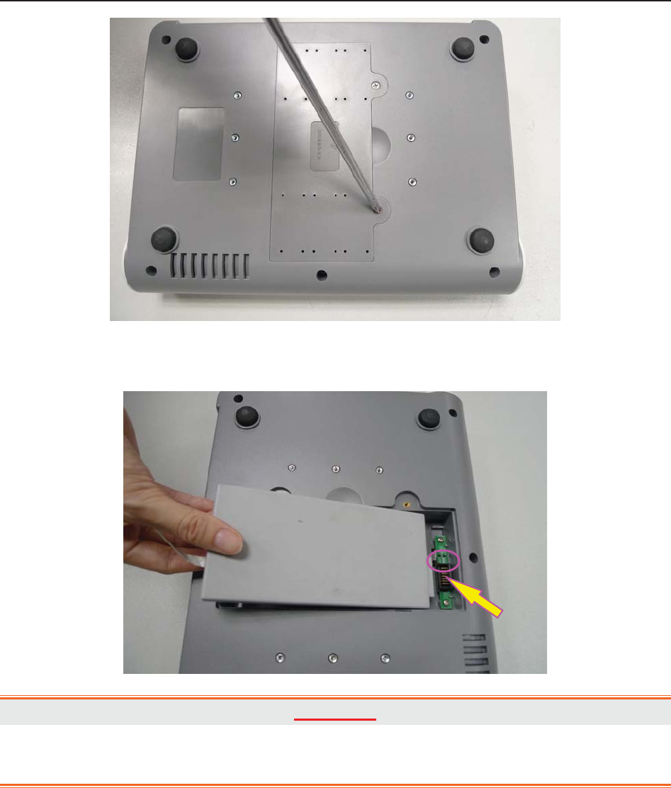
F9, F9 Express Fetal & Maternal Monitor User Manual FTS-3 Fetal Telemetry System
- 119 -
c) Take the battery out from package and put it into the compartment. Make sure the battery
connector is on the left and the battery label faces down.
WARNING
Do not touch the anode and cathode of the battery output together with fingers or metal
materials, avoiding hazards to you and the battery caused by the short-circuit.
d) Arrange the battery flat in the compartment, and push the strip at the end of the battery into
the gap.
Anode & Cathode of
Battery Output
Battery Connector

F9, F9 Express Fetal & Maternal Monitor User Manual FTS-3 Fetal Telemetry System
- 120 -
e) Shut the battery compartment cover and fix it with the screws.
(2) Battery Removal
Remove the battery in reverse order. You can pull the strip at the end to take the battery out from
the compartment.
NOTE:
1 If a rechargeable battery is outfitted, charge it fully each time after using the device to
ensure the electric power is enough.
2 When the battery configuration is provided, after the device is transported or stored,
the battery must be charged.
11.2.3 Installing the System
FTS-3 should be placed on a flat surface. It should be placed far from the device with strong
radiation and avoid being in the shielded room. More than 2 similar systems should be kept at a
distance of over 1.5m.
Alternatively, provided with proper devices, it can be installed on a wall or a trolley. Consult the
sales representative for more information.
CAUTION
1. Installation must be carried out by qualified personnel authorized by the
manufacturer.
2. If you choose to install FTS-3 on the wall, the ceiling or other locations, it is the
user’s responsibility to ensure their integrity and solidity evaluated by a registered,
professional structural or mechanical engineer and compliance with all local
regulations. The manufacturer will not be responsible for the failure and loss of any
improper installation.

F9, F9 Express Fetal & Maternal Monitor User Manual FTS-3 Fetal Telemetry System
- 121 -
CAUTION
3. This equipment has been tested and found to comply with the FCC Rules. These
limits are designed to provide reasonable protection against harmful interference in a
residential installation. This equipment generates uses and can radiate radio
frequency energy and, if not installed and used in accordance with the instructions,
may cause harmful interference to radio communications. However, there is no
guarantee that interference will not occur in a particular installation. If this equipment
does cause harmful interference to radio or television reception, which can be
determined by turning the equipment off and on, the user is encouraged to try to
correct the interference by one or more of the following measures:
-Reorient or relocate the receiving antenna.
-Increase the separation between the equipment and receiver.
-Connect the equipment into an outlet on a circuit different from that to which the
receiver is connected.
-Consult the dealer or an experienced radio/TV technician for help.
4. Operation of this equipment requires the prior coordination with a frequency
coordinator designated by the FCC for the Wireless Medical Telemetry Service.
11.2.4 Connecting Power Cable
Make sure the AC power supply of the system complies with the following specification:
100V-240V~, 50Hz/60Hz.
The equipotential grounding terminal is provided for the connection of a potential
equalization conductor. Therefore, it is recommended to connect the grounding terminal of
the system and the power outlet with the grounding wire, making sure FTS-3 is grounded.
WARNING
If the protective grounding (protective earth) system is doubtful, the power of the system
must be supplied by internal power supply only.
NOTE:
1 Make sure the system and the power outlet are placed at a place where it is easy to
connect and disconnect the power cord.
2 When the supply mains are interrupted, the device switches to internal power supply
and operates normally if the battery is installed. If the battery is not installed, the
system shuts down and resumes the previous settings at the subsequent operation.
3 After the AC power supply is connected, please wait for at least 2 seconds before
pressing the POWER switch to turn on the system.

F9, F9 Express Fetal & Maternal Monitor User Manual FTS-3 Fetal Telemetry System
- 122 -
11.2.5 Connect to the Base Station
1. Power on the base station.
2. Connect one end of the signal cable to the base station and the other end to the monitor
input socket.
3. Put the transducer back into the docking slot. The system can support 2 US transducers
and 1 TOCO transducer at most. Please do not exceed the maximum number of the
transducer.
NOTE:
If the system is provided with transducer protection cover, please do not take up the
cover during monitoring.
11.2.6 Configure the Monitor
1. Charge the transducer battery.
2. Power on the monitor.
3. Achieve the fetal heart signal.
Take the transducer up and keep the transducer at a distance of over 30cm from the base
station. The wireless connection indicator is on, and it indicates the transducer is taken
out. If you want to power off the transducer, put it back in the docking slot. If the
transducer connects to the base station successfully, the wireless connection indicator is
always on and do not put back the inactivated transducer in the docking slot.
4. Place the transducer on the patient.
NOTE:
1. Detailed operations please refer to 7.2.2 FHR Monitoring Procedure.
2. If the working status indicator is on, please do not put the uncharged transducer in
the docking slot.
3. The transducer has been taken first displays US1 on the screen, and that taken later
displays US2. Please do not take two US transducers simultaneously and wait at 2
seconds to take the other one.
11.2.7 Adjusting the Working Channel
If the fetal heart sound is with interference or it cannot be played smoothly, the working channel
is probably interfered. Put all the transducers back in the docking slots and press the adjustment
button in back of the base station. The channel range is 1-32.
Restart the system when it enters the charging interface.

F9, F9 Express Fetal & Maternal Monitor User Manual FTS-3 Fetal Telemetry System
- 123 -
NOTE:
The working channel number used by a system cannot be duplicate with that used by a
device of the same type.
11.3 Technical Alarm Messages
When FTS-3 is connected to F9 series fetal/maternal monitor, the monitor gives technical alarms
for the situations that need the physicians to pay attention to during wireless monitoring, The
alarm messages are listed below.
Alarm MessageCause Countermeasure
Medium Level
**Wireless US1
Transducer Battery
Low
The battery power is too low to
support further work of the
transducer.
Please charge the US1
transducer immediately.
** Wireless US2
Transducer Battery
Low
The battery power is too low to
support further work of the
transducer.
Please charge the US2
transducer immediately.
** Wireless TOCO
Transducer Battery
Low
The battery power is too low to
support further work of the
transducer.
Please charge the TOCO
transducer immediately.
** Base Station
Battery Low
The battery power is too low to
support further work of the base
station.
Connect the base station to AC
power supply.
Low Level
Wireless US1 SIGNAL
LOSS
FHR1 signal is too weak for the
system to analyze.
Check if the Wireless US1
transducer is aimed at the fetal
heart; check if the patient moves
out of the base station RF
range, if the transducer is well

F9, F9 Express Fetal & Maternal Monitor User Manual FTS-3 Fetal Telemetry System
- 124 -
connected to the base station.
Wireless US2 SIGNAL
LOSS
FHR2 signal is too weak for the
system to analyze.
Check if the Wireless US2
transducer is aimed at the fetal
heart; check if the patient moves
out of the base station RF
range, if the transducer is well
connected to the base station.
Wireless TOCO
SIGNAL LOSS
TOCO signal is too weak for the
system to analyze.
Check if the Wireless TOCO
transducer is placed correctly;
check if the patient moves out of
the base station RF range, if the
transducer is well connected to
the base station.
11.4 Basic Operation
11.4.1 Charge the Transducer
Place the transducer in the docking slot and it displays the charging state on the transducer
screen.
Caution
Please wait for 2 minutes to use the transducers after charging.
11.4.2 Charge the Battery
Please pay attention to the battery level during monitoring process. The battery symbol displays
in the top right corner of the screen. The low battery level may influence the monitoring.
: It is fully charged.
: It is less fully charged.
: It is in low level. Please charge the battery. There is alarm information on the screen.
: It is out of power. Please charge the battery immediately.
Caution
When in indicates the power is low, please charge the battery immediately or the
monitoring will be interrupted.
Please wipe the transducer and the charging point with a dry cloth before charging the transducer.
Please do not scratch the charging point.
The battery is installed in the transducer. If the base station is supplied by AC, the battery will be
charged automatically when it is placed in the docking slot. Please keep the transducer free of

F9, F9 Express Fetal & Maternal Monitor User Manual FTS-3 Fetal Telemetry System
- 125 -
water and coupling gel during charging.
When you charge the battery, the screen will display as follows:
x Full charging icon: fully charged.
x Increasing charging icon: charging
x No charging icon: the transducer place in the docking slot incorrectly.
x If the screen displays ERROR, it indicates that the transducer is not connected well or
you place the transducer from the other system by mistake.
It takes about 3.5 hours to charge the battery. It is recommended to place the transducer in the
docking slot when the transducer is not used for a long time.
Install the transducer in the base station and the transducer icon will display on the screen.
At the end of their life hand the batteries over to the applicable collection points for the recycling
of waste batteries. If the battery charging time decreases sharply, the battery is considered as
obsolete battery. Please use the battery provided by the manufacturer and disposes the battery
according to the local regulations.
11.4.3 Basic Function Test
Please test the system after each service.
1. Power on the base station and connect it to the fetal monitor.
2. Charge the transducer.
3. Power on the monitor.
4. Take up the US transducer and test the following function:
x The US transducer screen displays the standard start interface.
x The US transducer indicator is green.
x The fetal monitor screen displays US.
5. Simulate the audio frequency signal:
x The fetal monitor displays FHR.
6. Take up the TOCO transducer and test the following function:
x The TOCO transducer screen displays the standard start interface.
x The TOCO transducer indicator is green.
x The monitor screen displays TOCO.

F9, F9 Express Fetal & Maternal Monitor User Manual FTS-3 Fetal Telemetry System
- 126 -
7. Touch the measuring area of the TOCO transducer gently:
x The fetal monitor displays TOCO value change.
8. Install the US transducer to charge:
x The US transducer screen displays charging interface and charging state.
x The US transducer indicator is off.
x The fetal monitor screen is no display.
9. Install the TOCO transducer to charge:
x The TOCO transducer screen displays charging interface and charging state.
x The TOCO transducer indicator is off.
x The fetal monitor screen is no display.
10. It takes about 3.5 hours to charge the US transducer and TOCO transducer.
11.5 Patient Application
11.5.1 General Application
Take out the US transducer from the docking slot and it will power on automatically. The
transducer screen displays the signal strength, battery level and working channel. After the
transducer is successfully connected to the base station, it will also display the transducer type.
The indicators are yellow and blue.
NOTE:
1. Fix the US transducer and TOCO transducer tightly to ensure that they will not
shift during movement.
2. It is recommended that the transducer should be placed when the patient stands
for better monitoring.
3. Excessive coupling gel may slide the transducer.
4. Instruct the patient to move in the prescriptive area and distance for obtaining
better signal.
WARNING
If the patient is monitored underwater, please place the transducer when she is ready.
11.5.2 US Transducer
Apply the coupling gel to the transducer:
x Underwater monitoring requires less coupling gel or no coupling gel.
x Move the transducer to get the desire fetal heart and belt it to the belly.
NOTE:
1. When applied to the patient, the wireless ultrasound transducer may warm slightly

F9, F9 Express Fetal & Maternal Monitor User Manual FTS-3 Fetal Telemetry System
- 127 -
(less than 3°C (5.4ºF) above ambient temperature).
2. When NOT applied, the wireless ultrasound transducer may warm slightly (less than
3°C (5.4ºF) above ambient temperature).
11.5.3 Monitor the Ambulatory Patient
FTS-3 is suitable for ambulatory patients. You can take out the transducer from the docking slot
and fix the transducer on the location where the best fetal heart signal is received.
Please pay attention to the following during the monitoring.
x Ensure the transducer is tied up well.
x Record the effective FHR.
x The patient should not walk in strong tramps.
x The patient should move in the prescriptive area.
x The patient should be under monitoring when the wireless signal is good.
When the transducer is placed in the docking slot, the system stops transmission. It starts when
the monitor is connected to the transducer.
When the patient moves during monitoring, the interference may occur. The artificial interference
may influence the signal transmission quality. It will cause drop out or other interference if the
transducer works in the changing environment. Some kind of the artificial interference can be
anticipated and others can be discovered by observing the signal.
Some artificial interference may be caused by certain place. You can leave the place such as the
elevator or the window in iron for the place with signal reception.
The FHR may not be detected clearly when the patient moves in virtue of artificial interference.
The transducer is easy to shift underwater and it may lead to temporary signal loss.
No matter how good a telemetry system design is, the occasional US/TOCO dropouts are
inevitable. If it is not acceptable for certain patients, please connect the wired the transducer to
the bedside monitor.
The manufacturer has no control over the RF environment in the places where the system is used.
If interference exists at operating frequencies, the system performance will be affected. You can
change the working channel or move the system away from the interference to solve the problem.
Caution
Please do not mistake the patient’s steps for the fetal heartbeats.
11.5.4 Underwater Monitoring
Most wireless signal can be absorbed by water. Wireless transmission distances are shorter when
monitoring under water. If you have any question, just contact the manufacturer or the local
agent.

F9, F9 Express Fetal & Maternal Monitor User Manual FTS-3 Fetal Telemetry System
- 128 -
Caution
1. Please avoid flushing the transducer during underwater monitoring, or it may cause
wireless signal interference.
2. The transducers are watertight to a depth of 1.1 meter for 24 hours, but base station
is not waterproof. Please do not splash water about the station or soak it into any
liquid.
3. Underwater monitoring may influence the TOCO baseline in virtue of water
temperature and depth or other reasons. Please adjust the TOCO baseline until the
pressure of the transducer in water is steady and keep checking it.
4. A metal bath tub and underwater monitoring both reduce the operating range.
RF Exposure statement
The devices has been tested and meets applicable limits for Radio Frequency (RF)
exposure.
FCC statement
This device complies with part 15 of the FCC Rules. Operation is subject to the following two
conditions: (1)This device may not cause harmful interference, and (2) this device must accept
any interference received, including interference that may cause undesired operation.

F Series Fetal & Maternal Monitor User Manual After Monitoring
- 129 -
Chapter 12 After Monitoring
12.1 Completing Monitoring
After monitoring,
1) Remove transducers or electrodes from the patient; wipe the remaining gel off the
patient and the transducer with a clean soft cloth or tissue.
2) Press the PRINT key to stop printing, and press the paper advancing key to
advance the paper.
3) Wait the paper to stop and then tear it off along the perforation.
NOTE:
After the fetus is delivered in the labor, the monitor may pick up signals of the umbilical
cord and display a trace/numeric. To avoid misinterpretation, it is recommended to
remove the transducers from the patient and switch off the monitor immediately after the
fetus is delivered.
12.2 Switching Off
1) Press and hold the POWER switch for at least 3 seconds to switch off the monitor.
2) Unplug the power cord.
CAUTION
Do not press the POWER switch continuously. Allow at least 10 seconds between
switching the monitor on and off.

F Series Fetal & Maternal Monitor User Manual Maintenance and Cleaning
- 130 -
Chapter 13 Maintenance and Cleaning
13.1 Maintenance
13.1.1 Maintaining Inspection
(1) Visual Inspection
Prior to using the monitor or FTS-3 every time, do the following inspections:
Check the monitor and accessories to see if there is any visible evidence of damage that
may affect patient safety. Pay special attention to the cracks on the transducers and
cables before immersing them into conductive fluid.
Check all the outer cables, power socket and power cables.
Check if the monitor functions properly.
If any damage is detected, stop using the monitor or FTS-3 on the patient. Replace the damage
part(s) or contact the manufacturer for service before reusing it.
(2) Routine Inspection
The overall check of the monitor and the accessories, including safety check and function check,
should be performed by qualified personnel every 6 to 12 months, and each time after service.
The equipment should undergo periodic safety testing to ensure proper patient isolation from
leakage currents. This should include leakage current measurement and insulation testing. The
recommended testing interval is once a year or as specified in the institution’s test and inspection
protocol.
(3) Mechanical Inspection
Make sure all exposed screws are tight.
Check the external cables for splits, cracks or signs of twisting.
Replace any cable that shows serious damage.
Pay particular attention to the supply socket.
WARNING
Failure on the part of the responsible individual hospital or institution employing the use
of this equipment to implement a satisfactory maintenance schedule may cause undue
equipment failure and possible health hazards.
CAUTION
Besides the maintenance requirements recommended in this manual, comply with local
regulations on maintenance and measurement.

F Series Fetal & Maternal Monitor User Manual Maintenance and Cleaning
- 131 -
13.1.2 Maintenance of Monitor and Base Station
Keep the exterior surface of the monitor and the base station clean, free of dust and dirt.
The gathering of dew on the screen may occur with abrupt temperature or humidity changes. A
stable environment is recommended. Stop using the monitor or the base station and contact the
service personnel immediately if accidental wetting occurs.
Scratching and damaging the screen should be avoided.
Operate the touch screen with special stylus pen or finger. Sharp edged or hard particles like ball
pen or propelling pencil are prohibited. Keep the touch screen surface clean, and no adhesive
should be applied. Avoid high voltage and static charge.
13.1.3 Maintenance of Wired and Wireless Transducers
Although transducers are designed for durability, they should be handled with care. Rough
handling could damage the cover, piezoelectric crystals and mechanical movement. Contacting
the transducers with hard or sharp objects should be avoided. Do not excessively flex the cables.
The transducers must be cleaned before docking in the base station after each use. Make sure that
there is no residual coupling gel. Besides, the transducers must be thoroughly cleaned and
disinfected at least once a month. When cleaning, please firstly use a lint-free cloth moistened
with mild near neutral detergent, ethanol 75% solution or isopropanol 70% alcohol-based
solution to clean the transducers. Then use a cotton cloth moistened with clear water to clean
again. At last, use a dry, soft cloth to dry them.
In case of unsuccessful charge or poor contact, please use detergent with abrasive effect to rub the
electrodes of the transducers in order to clear away the oxide of coupling gel.
Charge and discharge the wireless transducer battery every 3 months.
13.1.4 Storage of Recorder Paper
When storing recorder paper (including used paper with traces):
Do not store in plastic envelopes.
Do not leave exposed to direct sunlight or ultraviolet light.
Storage conditions outside these limits may distort the paper and adversely affect the accuracy of
grid lines or make the trace unreadable.
13.1.5 Cleaning of Recorder
The recorder platen, thermal print head and paper sensing mechanism must be cleaned at least
once a year or when needed (when traces become faint).
To do this:

F Series Fetal & Maternal Monitor User Manual Maintenance and Cleaning
- 132 -
1) Clean the recorder platen with a lint-free cloth dampened in soap/water solution.
2) Wipe the thermal array using a cotton swab moistened with 70% Isopropyl alcohol-based
solution.
3) Check that the paper sensing mechanism is free of dust.
WARNING
Switch off the monitor and remove the power cord prior to recorder cleaning.
13.1.6 Maintaining the Battery
It is required to follow the instructions in this user manual during installation, storage and
maintenance of the battery.
When the battery is charged, used or stored, keep it away from objects or materials with static
electric charges.
The recommended charge temperature range is from 0 ºC (+32 ºF) to +40 ºC (+104 ºF). Do not
exceed this range.
When not using battery for an extended period, remove it from the monitor and store it in a place
with low humidity and low temperature.
Batteries have life cycles. If the time that the monitor uses the battery becomes much shorter than
usual, the battery life is at an end. Replace it with a new one the same as the one provided or
recommended by the manufacturer.
13.2 Cleaning
In order to avoid infection, clean and disinfect the monitor and accessories after each use.
13.2.1 Cleaning of Monitor and Base Station
Regular cleaning of the monitor enclosure and the screen is strongly recommended.
WARNING
1 Unplug the monitor and the base station from the AC power source and detach all
accessories before cleaning. Do not immerse the unit in water or allow liquids to enter
the case.
2 If liquid is splashed on or into the main unit inadvertently, or enters the conduit, stop
using the monitor and contact the manufacturer for service immediately.
The solutions recommended for monitor cleaning are: mild near neutral detergent, ethanol 75%
and isopropanol 70%.
Clean the monitor and the base station enclosure with soft cloth and diluent non-caustic
detergents recommended above.
Clean the screen and the charging point in the docking slot with a dry soft cloth.

F Series Fetal & Maternal Monitor User Manual Maintenance and Cleaning
- 133 -
CAUTION
1 Although the monitor and the base station are chemically resistant to most common
hospital cleaners and non-caustic detergents, different cleaners are not
recommended and may stain the monitor.
2 Many cleansers must be diluted before use. Follow the manufacturer’s directions
carefully to avoid damaging the monitor and the base station.
3 Do not use strong solvent, for example, acetone.
4 Never use an abrasive such as steel wool or metal polish.
5 Do not allow any liquid to enter the product, and do not immerse any part of the
monitor into any liquid.
6 Avoid pouring liquids on the monitor while cleaning.
7 Do not allow any remaining solution on the surface of the monitor.
NOTE:
1 The monitor surface can be cleaned with hospital-grade ethanol and dried in air or
with crisp and clean cloth.
2 The manufacturer has no responsibility for the effectiveness of controlling infectious
disease using these chemical agents. Please contact infectious disease experts in
your hospital for details.
13.2.2 Cleaning of Accessories
(1) Cleaning of Transducers
To clean the transducers and leads, follow these steps:
1) Wipe them with a soft cloth dampened in cleaning solution;
2) Clean them with a soft cloth dampened in water;
3) Air-dry them or wipe the remaining moisture with a soft dry cloth.
The recommended cleansers for accessories are listed below:
Accessory Cleansers
Ultrasound Transducer
TOCO Transducer
(Including the wireless) Mild near neutral detergent Ethanol 75% Isopropanol 70%
DECG Leads Mild near neutral detergent Ethanol 75% Isopropanol70%
IUP Cable Mild near neutral detergent Ethanol 75% Isopropanol 70%
ECG Leads Mild near neutral detergent Ethanol 75% Isopropanol70%
SpO2 Sensor Mild near neutral detergent Ethanol 75% Isopropanol70%
TEMP Sensor Mild near neutral detergent Ethanol 75% Isopropanol70%

F Series Fetal & Maternal Monitor User Manual Maintenance and Cleaning
- 134 -
CAUTION
1 The waterproof parts of the transducer are restricted to the main body and the cable.
Do not immerse the plug into water during the process of monitoring or cleaning.
2 Be sure the temperature of cleaning solutions does not exceed +45 ºC (+113 ºF).
3 Only wipe the outer surface of accessories. Do not immerse them in any liquid.
4 Make sure no liquid enters the connector.
5 When you clean the TEMP transducer, take the head in one hand and clean with the
soft cloth in the other hand.
6 After cleaning, no remaining cleanser is allowed on the surface.
7 Please clean the charging point periodically or it will not be charged.
(2) Cleaning of Belt
Wash soiled belts with soap and water. The water temperature must not exceed +60 ºC (+140 ºF).
(3) Cleaning of NIBP Cuff
The cuff can also be machine-washed or hand-washed. Hand-washing will prolong the life of the
cuff.
Remove the latex rubber bag before washing; for machine-washing, close the Velcro fastening.
Allow the cuff to dry thoroughly after washing; then reinsert the rubber bag.
Replace the Rubber Bag in the Cuff
To replace the rubber bag in the cuff, first place the bag on the top of the cuff so that the rubber
tubes line up with the large opening on the long side of the cuff. Now roll the bag lengthwise and
insert it into the opening on the long side of the cuff. Hold the tubes and the cuff and shake the
complete cuff until the bag is in position. Thread the rubber tubes from inside the cuff, and out
through the small hole under the internal flap.
Figure 12-1 Replace the Rubber Bag in the Cuff

F Series Fetal & Maternal Monitor User Manual Maintenance and Cleaning
- 135 -
CAUTION
1 Do not squeeze the rubber tube on the cuff.
2 Do not dry-clean the cuff.
3 Only clean the outer surface of the connectors, make sure no liquid goes into the
connector.
4 When the reusable cuff is not connected with the monitor, or being cleaned, always
place the cover on the rubber tube to avoid liquid permeation.
13.3 Disinfecting
To disinfect the transducers and leads, follow these steps:
1) Clean the accessories.
2) Wipe them with a soft cloth dampened in the recommended disinfectant.
3) Wipe them clean with a soft cloth dampened in water.
4) Air-dry them or wipe the remaining moisture with a soft dry cloth.
The table below lists the allowed disinfectant bases:
Type Recommended
Fetal/Maternal Monitor
Ethanol 75%
Isopropanol 70%
Ethanol 75%
Isopropanol 70%
Base Station
US and TOCO Transducers
(the wired and wireless)
Remote Event Marker
DECG Cable
IUP Cable
ECG Leads
SpO2 Transducer
TEMP Transducer
NIBP Cuff
NIBP Cuff Extension Tube

F Series Fetal & Maternal Monitor User Manual Maintenance and Cleaning
- 136 -
CAUTION
1 Do not use any disinfectant containing additional active ingredients other than those
listed.
2 Follow the manufacturer’s instruction to dilute the solution, or adopt the lowest
possible density.
3 Do not immerse any part of the monitor or any accessory into liquid.
4 After disinfection, no remaining disinfectant is allowed on the surface.
5 Check if the monitor and accessories are in good condition. If any aging or damage is
detected (e.g. the belt loses its elasticity), replace the damage part(s) or contact the
manufacturer for service before reusing them.
6 Please do not light the TOCO transducer with ultraviolet light for a long time.
NOTE:
The manufacturer has no responsibility for the effectiveness of controlling infectious
disease using these chemical agents. Please contact infectious disease experts in your
hospital for details.
13.4 Sterilizing
Do not sterilize the monitor, the base station or the accessories, unless this is necessary according
to your hospital regulation.
NOTE:
Check if the monitor, the base station, cables and accessories function well. If any
problem is detected, please contact the manufacturer for service before reusing them.
Checking Item Checking Method
Visual Inspect the monitor, base station and cables etc. for any damage.
Power On Power on the monitor. Does it boot up successfully without errors and enter the
main menu?
Functionality Test After power up, check whether the AC power indicator and battery status
indicator in the bottom left of the screen display as stated in 3.3.1 section.
Performance Please check the US transducer and TOCO transducer according to 7.2.6
Testing US Transducers and 7.5.4 Testing TOCO Transducers. FTS-3 wireless
transducers also can be tested accordingly.
System When the monitor is connected to FTS-3, please check whether the base
station working channel and its battery status indicator in the bottom right of the
screen display as stated in 3.3.1 section.

F Series Fetal & Maternal Monitor User Manual Warranty and Service
- 137 -
Chapter 14 Warranty and Service
14.1 Warranty
EDAN warrants that EDAN’s products meet the labeled specifications of the products and will be
free from defects in materials and workmanship that occur within warranty period.
The warranty is void in cases of:
a) damage caused by mishandling during shipping.
b) subsequent damage caused by improper use or maintenance.
c) damage caused by alteration or repair by anyone not authorized by EDAN.
d) damage caused by accidents.
e) replacement or removal of serial number label and manufacture label.
If a product covered by this warranty is determined to be defective because of defective materials,
components, or workmanship, and the warranty claim is made within the warranty period, EDAN
will, at its discretion, repair or replace the defective part(s) free of charge. EDAN will not provide
a substitute product for use when the defective product is being repaired.
14.2 Contact information
If you have any question about maintenance, technical specifications or malfunctions of devices,
contact your local distributor.
Alternatively, you can send an email to EDAN service department at: support@edan.com.cn.

F Series Fetal & Maternal Monitor User Manual Product Specifications
- 138 -
Appendix 1 Product Specifications
A1.1 Environmental Specifications
The monitor may not meet the performance specifications given here if stored or used outside the
specified temperature and humidity ranges.
Working
Temperature: +5 ºC ~ + 40 ºC ( +41 ºF ~ +104 ºF)
Relative Humidity: 15% ~ 93% (non-condensing)
Atmospheric Pressure: 860hPa ~ 1060hPa
Transport and Storage
Temperature: -20 ºC ~ +55 ºC (-4ºF ~ +131 ºF)
Relative Humidity: 15% ~ 93% (non-condensing)
Atmospheric Pressure: 700hPa ~ 1060hPa
A1.2 Physical Specifications
Monitor
Dimensions and Weight
Size (depth x width x height): 347mm × 330mm × 126mm
Weight:
F6: Approx. 5.3 kg
F6 Express: Approx. 6.1kg
F9: Approx. 5.5 kg
F9 Express: Approx. 6.3 kg
Power Supply
Operating Voltage: 100V-240V~
Operating Frequency: 50Hz/60Hz
Input Power : 1.0A-0.5A
Battery: 14.8VDC/5000mAh
Standards Compliance
IEC 60601-1:2005,
EN 60601-1:2006/AC:2010,
IEC 60601-1-2:2007,
EN 60601-1-2:2007/AC:2010,
IEC/EN 60601-2-27,
IEC/EN 60601-2-37,
IEC/EN 60601-2-49,

F Series Fetal & Maternal Monitor User Manual Product Specifications
- 139 -
IEC 80601-2-30,
ISO 80601-2-61,
ISO 80601-2-56,
EN 12470-4,
AAMI/ANSI EC13
Anti-electric Shock Type Class I equipment with internal power supply
Anti-electric Shock Degree
FHR1, FHR2, TOCO, FM, IUP
SpO2, NIBP
DECG
ECG, TEMP
BF
BF (Defibrillating-proof)
CF
CF (Defibrillating-proof)
Degree of Protection against
Harmful Ingress of Water
Main Unit:
IPX1, protected against vertically falling water
drops(provided recorder drawer is shut and the monitor is
not mounted on the wall vertically)
US/TOCO Transducers: IPX8, protected against the
effects of continuous emersion in water
Degree of Safety in Presence of
Flammable Gases
Equipment not suitable for use in presence of flammable
gases
Disinfection/Sterilizing Method: Refer to this user manual for details
EMC CISPR11 Group 1 Class A
Working System Continuous running equipment
Display (F6/F6 Express)
LCD Size: 10.1” (Diagonal)
Resolution: 800 × 480
Display (F9/F9 Express)
Screen Diagonal: 12.1”
Pixel: 800(H) × 600(V)
Signal Interface
DB9 network interface, RJ45 interface
Ultrasound Transducer
Cable Length: 2.5m
Weight: 190 g

F Series Fetal & Maternal Monitor User Manual Product Specifications
- 140 -
Dimension: 88 mm × 35 mm
TOCO Transducer
Cable Length: 2.5 m
Weight: 180 g
Dimension: 88 mm × 35 mm
Remote Event Marker
Length: 2.5 m
Weight: 56 g
ECG
Cable Length: 3 m
Weight: 213 g
SpO2
Cable Length: 2.4 m
Weight: 68 g
NIBP
Cable Length: 3.3 m
Weight: 194 g
TEMP
Cable Length: 3 m
Weight: 55 g
A1.3 Performance Specifications
Ultrasound
Technique: Ultrasound Pulse Doppler with autocorrelation
Pulse Repetition Rate: 2 KHz
Pulse Duration: 92 μs
Ultrasound Frequency: (1.0±10%) MHz
Ultrasound Signal Range: 3.5uV Vpp~350 uV Vpp
p- <1 MPa
Iob <10 mW/cm2
Ispta <100 mW/cm2
Isata<20 mW/cm2

F Series Fetal & Maternal Monitor User Manual Product Specifications
- 141 -
Isppa.3<190W/cm2
Ispta.3<94mW/cm2
Max Output Power <15mW
Effective Radiating Area: 942 mm2 ± 15%
FHR Measurement Range: 50 bpm ~ 240 bpm
Resolution: 1 bpm
Accuracy: ±2 bpm (F6/F6 Express)
±1 bpm (F9/F9 Express)
Dielectric Strength: 4000Vrms
Maximum transducer
temperature rise during
use:
Less than 5 qC (9ºF)
Expanded uncertainty of
temperature test: U=0.4qC (0.72ºF), k=2
DECG
Technique: Peak-peak detection technique
DFHR Measurement
Range: 30bpm ~ 240bpm
Resolution: 1bpm
Accuracy: ±1bpm
Input Impedance: > 10M (Differential, DC50/60Hz)
Input Impedance: > 20M (Common Mode)
CMRR: > 110dB
Noise: < 4μVp
Skin Voltage Tolerance: ±500mV
Fetal Input Voltage
Current: 20μVp-3mVp
TOCO
TOCO Range: 0% ~ 100%
Non-linear Error: ±10%
Baseline Drift due to
Temperature Changes
1 unit/min/°C (free air)
5 units/min/°C (underwater)
Resolution: 1%
Zero Mode: Automatic(TOCO value becomes zero or below
lasting for 30 seconds)/ Manual
Dielectric Strength: 4000Vrms
IUP Pressure Range: 0 ~ 100mmHg
Sensitivity: 5μV/V/mmHg

F Series Fetal & Maternal Monitor User Manual Product Specifications
- 142 -
Non-linear Error: ± 3mmHg
Resolution: 1%
Zero Mode: Manual
Fetal Movement
Technique: Pulsed Doppler ultrasound
FM Mode Automatic/Manual
AFM Mode Trace or blackmark
Display
Range 0-999
ECG
HR Measurement Range: 30 bpm ~ 240 bpm
Input Signal Range: ±8 mV PP
HR Measuring Accuracy: ±2 bpm
ECG Waveform: Manual control ECG waveform display
ECG falls off: Detect automatically
Patient Leakage Current
(Limit)
N.C. S.F.C.
d.c. 10μA 50μA
a.c. 10μA 50μA
Patient Auxiliary Current
(Limit)
N.C. S.F.C.
d.c. 10μA 50μA
a.c. 10μA 50μA
Differential Input
Impedance >5Mȍ
Display Sensitivity 2.5mm/mV (×0.25), 5mm/mV (×0.5), 10mm/mV
(×1), 20mm/mV (×2), AUTO gain
Sweep speed 25mm/s
d.c. Offset Voltage
Tolerance ±500mV
Auxiliary Current (Leads
off detection)
Active electrode: < 100 nA
Reference electrode: < 900 nA

F Series Fetal & Maternal Monitor User Manual Product Specifications
- 143 -
ECG
Accuracy and
Response to Irregular
Rhythm
According with ANSI/AAMI EC13-2002
Sect.4.1.2.1 e)
The HR value displays after a stable period of 20s:
Ventricular bigeminy: 80bpm±1bpm
Slow alternating ventricular bigeminy: 60bpm±1bpm
Rapid alternating ventricular bigeminy: 120bpm±1bpm
Bidirectional systoles: 91bpm±1bpm
Response time to Change
in HR
HR range: 80bpm ~ 120bpm
Range: 7s ~ 8s (average: 7.5s)
HR range: 80bpm ~ 40bpm
Range : 7s ~ 8s (average: 7.5s)
Accuracy of HR Alarm
Limit1 bpm
Tall T-wave Rejection
Exceeds ANSI/AAMI EC13-2002 Sect. 4.1.2.1 (C)
minimum recommended 1.2mV T-Wave
amplitude
HR averaging method Heart rate is computed by averaging the 12 most
recent RR intervals.
SpO2
Measurement Range: 50% ~ 100%
Resolution: 1%
Measuring Accuracy
(EDAN):
90% ~ 100% ± 2%
70% ~ 90% ± 4%
< 70% unspecified
Measuring Accuracy
(Nellcor):
70% ~ 100% ± 2%
< 70% unspecified
Data Update Period: 2 seconds (typically)
10 seconds (in extreme condition)
PR Measurement Range: 30 bpm ~ 240 bpm
PR Measuring Accuracy: ±3 bpm
Data update period
(EDAN):: 1s
Data update period
(Nellcor): 2s
Wave length
Red light (660r3) nm

F Series Fetal & Maternal Monitor User Manual Product Specifications
- 144 -
Infrared light (905r10) nm
Emitted light energy < 15 mW
Information about the wave length range can be especially useful to clinicians
(for instance, when photodynamic therapy is performed.)
NIBP
(for adult)
Measurement Range:
Systolic pressure: 40mmHg ~ 270mmHg
Diastolic pressure: 10mmHg ~ 215mmHg
Measuring Time: 120 seconds
Software Over Voltage
Protection: (297 r 3) mmHg
Hardware Over Voltage
Protection: (320 r 10) mmHg
Cuff pressure measuring
range:
0 mmHg ~ 300 mmHg
Resolution: 1 mmHg
Measuring Accuracy
Max. average deviation: r5mmHg
Max. standard deviation: 8mmHg
TEMP
Channel: 1
Measuring Mode: Direct Mode
Position: Axilla
Measurement Range: 0ºC ~ +50ºC (+32ºF ~ +122ºF)
Accuracy:
(sensor error excluded)
0ºC ~ +25ºC (+32ºF ~ +77ºF): ± 0.2ºC (±0.36ºF)
+25ºC ~ +45ºC (+77ºF ~ +113ºF): ± 0.1ºC (±0.18ºF)
+45ºC ~ +50ºC (+113ºF ~ +122ºF): ± 0.2ºC (±0.36ºF)
Refresh Time: Every 1s to 2s
Accessory: TEMP sensor
A1.4 Recorder Specifications
Paper: Z-fold, thermosensitive
(compatible with GE and PHILIPS recorder paper)
Paper width: 152mm (GE), 150mm (PHILIPS)

F Series Fetal & Maternal Monitor User Manual Product Specifications
- 145 -
Effective printing width: 110mm (American Standard)
120mm (International Standard)
FHR printout width: 70mm (American Standard)
80mm (International Standard)
FHR scaling: 30bpm/cm (American Standard)
20bpm/cm (International Standard)
TOCO printout width: 40mm
TOCO scaling: 25%/cm
Printing speed:
Standard Speed (Real-Time Traces ): 1 cm/min, 2 cm/min, 3 cm/min
Fast Print Speed (Stored Traces): Up to 15mm/sec
Accuracy of data: ± 5% (X axis) ± 1% (Y axis)
Resolution: 8 dots/mm
Record Information:
FHR1 trace/mark, FHR2 trace/mark, TOCO trace,
AFM trace/black mark, fetal movement mark, event
mark (and annotation), AUTO-zero symbol, alarm
indicator, date, time, printing speed, ID, name, FHR2
Offset, HR, SpO2, SYS, DIA, TEMP, CTG analysis
results etc.
A1.5 Rechargeable Lithium-ion Battery
Type: Rechargeable Lithium-ion Battery
Continual Working Time: >2 hours
Necessary Charge Time: <7hours
Nominal Capacity: 5000mAh
Nominal Voltage: 14.8V
Cycle Life: > 300 times

F Series Fetal & Maternal Monitor User Manual Product Specifications
- 146 -
A1.6 Low Output Summary Table
Low Output Summary Table
(for systems with no transducers having global maximum index values exceeding 1.0)
System: Fetal & maternal Monitor
Transducer Model Ispta.3
(mW/cm2) TI Type TI Value MI Ipa.3@MImax
(W/cm2)
PW1.0MHz
(F6/F6 Express US
Transducer)
1.288
TIS 0.006149
0.014050.007225
TIB 0.04687
PW1.0MHz
(F9/F9 Express US
Transducer)
1.817
TIS 0.008761
0.01567 0.01025
TIB 0.05723

F Series Fetal & Maternal Monitor User Manual Product Specifications
- 147 -
B FTS-3 Fetal Telemetry System
B1.1 Environmental Specifications
Working
Temperature: +5 ºC ~ +40 ºC (+41ºF ~ +104ºF)
Relative Humidity: 15% ~ 93% (non-condensing)
Atmospheric Pressure: 860hPa ~ 1060hPa
Transport and Storage
Temperature: -20 ºC ~ +55 ºC (-4ºF ~ +131 ºF)
Relative Humidity: 15% ~ 93% (non-condensing)
Atmospheric Pressure: 700hPa ~ 1060hPa
B1.2 Physical Specifications
Size: 250x200x85mm
Weight: Approximately 1.8 kg
Power Supply
Operating Voltage: 100V-240V~
Operating Frequency: 50Hz/60Hz
Input Power : 0.8A-0.3A
Battery: 14.8VDC/5000mAh
Standards Compliance
IEC 60601-1:2005,
EN 60601-1:2006/AC:2010,
IEC 60601-1-2:2007,
EN 60601-1-2:2007/AC:2010,
IEC/EN 60601-2-37.
FCC 47 CFR Part 95
Anti-electric Shock Type Class I equipment with internal power supply
Anti-electric Shock Degree FHR1, FHR2, TOCO BF
Degree of Protection against
Harmful Ingress of Water IPX8
Degree of Safety in Presence
of Flammable Gases
Equipment not suitable for use in presence of flammable
gases

F Series Fetal & Maternal Monitor User Manual Product Specifications
- 148 -
Disinfection/Sterilizing
Method Refer to this user manual for details
EMC CISPR11 Group 1 Class A
Ground Leakage Current
(Limit):
N.C. S.F.C.
500μA 1000μA
Enclosure Leakage Current
(Limit)
N.C. S.F.C.
100μA 500μA
Patient Leakage Current
(Limit):
N.C. S.F.C.
d.c. 10μA 50μA
a.c. 100μA 500μA
Patient Auxiliary Current
(Limit):
N.C. S.F.C.
d.c. 10μA 50μA
a.c. 100μA 500μA
Base Station
Weight: 1.8 kg
Size: 310mm x 235mm x81mm
US Transducer
Weight: About 150 g
Size: Ø81 mm × 35 mm
TOCO Transducer
Weight: About 150 g
Size: Ø81 mm × 35 mm
B1.3 Performance Specifications
Ultrasound
Technique: Ultrasound Pulse Doppler with autocorrelation
Pulse Repetition Rate: 2 KHz
Pulse Duration: 92 μs
Ultrasound Frequency: (1+10%) MHz

F Series Fetal & Maternal Monitor User Manual Product Specifications
- 149 -
p_< 1 MPa
Iob<10 mW/cm2
Ispta<100 mW/cm2
FHR Measurement Range: 50 bpm ̚ 240 bpm
Resolution: 1 bpm
Accuracy: ±2 bpm
Dielectric Strength: 4000 Vrms
TOCO
TOCO Range: 0% ~ 100%
Non-linear Error: ±10%
Baseline Drift due to
Temperature Changes
1 unit/min/°C (free air)
5 units/min/°C (underwater)
Resolution: 1%
Zero Mode: Automatic/ Manual
Dielectric Strength: 4000 Vrms
RF Index
Transmission Power: < 10mW e.r.p
Frequency Range: 608.00MHz~614.00MHz
Transmission Range (line of
sight): >110m
Modem Mode: FSK
Transmission Rate: About 25kbps
Channel Range: 1~32
Transducer Antenna: FM antenna
Base Station Antenna: Internal antenna

F Series Fetal & Maternal Monitor User Manual Product Specifications
- 150 -
B1.4 Rechargeable Lithium-ion Battery
Base Station Battery
Nominal Capacity: 5000 mAh
Continuous Work
Time: 40 Hours
Nominal Voltage: 14.8 V
Necessary Charge
Time: 14 Hours
Cycle Life: >300 times
Transducer Battery
Nominal Capacity: 1600 mAh
Charge Current
(Standard): 700 mA
Continuous Work
Time: >16 Hours
Nominal Voltage: 3.7 V
Charge Voltage
(Standard): (4.2±0.1) V
Cycle Life: 500 times
B1.5 Low Output Summary Table
Low Output Summary Table
(for systems with no transducers having global maximum index values exceeding 1.0)
System: Fetal Telemetry System
Transducer Model Ispta.3
(mW/cm2) TI Type TI Value MI Ipa.3@MImax
(W/cm2)
PW1.0MHz 0.6186
TIS 0.002949
0.01087 0.003412
TIB 0.01939

F Series Fetal & Maternal Monitor User Manual Signal Input/Output Connector
- 151 -
Appendix 2 Signal Input/Output Connector
Accessory equipment connected to these interfaces must be certified according to the respective
IEC/EN standards (e.g. IEC/EN 60950 for data processing equipment and IEC/EN 60601-1 for
medical equipment). Furthermore all configurations shall comply with the valid version of the
system standard IEC/EN 60601-1-1. Anybody who connects additional equipment to the signal
input connector or signal output connector to configure a medical system must ensure that the
system complies with the requirements of the valid version of the system standard IEC/EN
60601-1-1. If in doubt, contact our technical service department or your local distributor.
DB9 Interface
D-Sub Interface
Pin Signal Input/Output
1 +5V Output
2 Rx Input
3 Tx Output
4 485EN Input
5 0V Ref.
6 TA Output
7 TB Output
8 RA Input
9 RB Input
Pin Signal Input/Output
1 US2 Input
2 ISOCNS_RXD Input
3 ISOCNS_TXD Output
4 485EN Input
5 0V Ref.
6 TA Output
7 TB Output
8 RA Input
9 RB Input
10 DECG_SIGNAL Input
11 US1 Input
12 +5V Output
13 TOCO Input
14 DECG_GND
15 EN Input
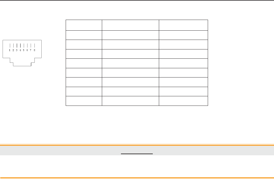
F Series Fetal & Maternal Monitor User Manual Signal Input/Output Connector
- 152 -
RJ45 Interface
CAUTION
Only the PC recommended by the manufacturer can be connected to the signal
input/output interface of the monitor. Other equipment is forbidden.
Pin Signal Input/Output
1 TD+ Output
2 TD- Output
3 RD+ Input
4 Reserved
5 Reserved
6 RD- Input
7 Reserved
8 Reserved

F Series Fetal & Maternal Monitor User Manual Troubleshooting
- 153 -
Appendix 3 Troubleshooting
A3.1 No Display
Phenomenon Possible Cause Solution
Power indicator is off.
Power cable is loose. Tighten the power cable.
The fuse is blown. Change the fuse.
The battery runs out of power. Connect to AC power supply.
A3.2 Noise
Phenomenon Possible Cause Solution
Noise
Too high volume setup. Turn down the volume.
Interfered by mobile phone or
other electromagnetic interference
source.
Turn off or move the
interference source.
Move the monitor to a place
with less interference.
A3.3 Recorder Error
Phenomenon Possible Cause Solution
Paper jam Wrong loading paper or paper is
dampened.
Load paper correctly and keep
paper from moist.
Recorder does not work.
The recorder is not started. Press the PRINT key.
Run out of paper. Load paper.
The paper drawer is not locked.
Slide the paper drawer in until
both latches are locked in
position.

F Series Fetal & Maternal Monitor User Manual Troubleshooting
- 154 -
A3.4 Trouble with Ultrasound FHR Monitoring
Phenomenon Possible Cause Solution
Inconstant trace
/ display
The patient is overweighted. Monitor FHR with DECG.
Improper ultrasound transducer
position.
Adjust the position of the
transducer till the better signal is
received.
Loose belt. Tighten the belt.
Superfluous aquasonic coupling
gel.
Wipe off superfluous aquasonic
coupling gel.
Frequent fetal movements. Delay the monitoring.
Maternal movement. Request the patient to calm down
and stay still.
Inadequate aquasonic coupling
gel.
Use recommended aquasonic
coupling gel quantity.
Doubtful FHR
Record maternal heart rate
wrongly.
Change the position of the
ultrasound transducer.
The transducer is not well placed
in position, and the mixed noise
has been recorded.
Adjust the position of the
transducer.
Feint trace or no trace
Improper paper. Use paper recommended by the
manufacturer.
The paper drawer is not locked.
Slide the paper drawer in until
both latches are locked in
position.
Adjusting nuts of the print head
are unbalanced.
Contact the manufacturer for
service.
A3.5 Troubles with DECG FHR Monitoring
Symptom Possible Cause Solution
Inconstant trend
Inconstant display
No ECG signal Use a new spiral electrode
Bad contact of reference electrode
and patient Use a new spiral electrode

F Series Fetal & Maternal Monitor User Manual Troubleshooting
- 155 -
Inconstant trend The DECG cable has not been
fixed firmly
Fix an attachment pad at the
DECG cable.
A3.6 Troubles with Contractions Monitoring (External)
Phenomenon Possible Cause Solution
Bad trace quality or
fluctuant TOCO baseline
The belt is too tight or too loose. Adjust the belt.
The belt has no elasticity. Renew the belt.
Maternal movement. Request the patient to calm
down and stay still.
Frequent fetal movements. Delay the monitoring.
Too high TOCO
sensitivity (higher than
100 unit)
The body pressure from uterus to
TOCO transducer is far higher
than the average numeric.
Insure favorable contact for
patient skin with TOCO
transducer. Change the position
of TOCO transducer, if
necessary.
A3.7 Troubles with Monitoring Contractions (Internal)
Symptom Possible Cause Solution
No trend The intrauterine catheter is
jammed. Wash with disinfector.
No pressure change
when uterine contraction
“Dry” environment or the tip of
intrauterine catheter is placed
extraovularly.
Wash with disinfector or change
the position of transducer.
Only see the IUP peak
but no baseline Zero adjustment is wrong. Zero the system.
The trend is a beeline The connector failure.
Move or contact catheter. If
trend no fluctuation, change
intrauterine cable.

F Series Fetal & Maternal Monitor User Manual Troubleshooting
- 156 -
A3.8 Big ECG Signal Interference or Thick Baseline
Phenomenon Possible Cause Solution
Big ECG signal
interference or thick
baseline
Abnormal electrodes placing or
electrodes invalidation.
Check the electrodes placing and
the period of validity of electrodes.
The cable connector is not well
connected.
Check the connection of cable
connector.
Power socket has no standard
ground wire.
Check if power socket has
standard ground wire.
The special ground wire
connecting with monitor is not
properly earthed.
Check if the special ground wire
connecting with monitor is
earthed.
A3.9 NIBP and SpO2 No Results
Phenomenon Possible Cause Solution
NIBP and SpO2 have no
results
The NIBP cuff is not properly
wrapped to the position of
patient's arm.
Check if the NIBP cuff is properly
wrapped to the position of
patient's arm.
The NIBP can not be inflated. Extend catheter, and check the
connection.
Hose connector plug is not
connected well with the NIBP
socket.
Check if the hose connector plug
is connected well with the NIBP
socket.
SpO2 sensor is not connected
well with the SpO2 socket.
Check if the SpO2 sensor is
connected well with the SpO2
socket.
Abnormal working condition. Shut off the power, then switch it
on again.
A3.10 Blown Fuses
WARNING
Switch off the monitor and unplug it before changing the fuse.
Replace the fuse when it is blown.
The two fuses of the monitor are located on the bottom panel, their specifications are:
Size: Ɏ5mm*20mm; Model: T2AH250V.
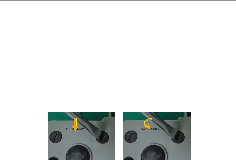
F Series Fetal & Maternal Monitor User Manual Troubleshooting
- 157 -
To replace a fuse:
1 Fold the LCD display completely flat.
2 Carefully place the monitor upside down on a flat surface covered with cloth or other
protecting pad.
3 With a flat-head screw driver, push the fuse in for about 1 mm and then unscrew it
anticlockwise.
4 Remove the old fuse and replace it with a new fuse that is supplied by the manufacturer or of
the same specifications.
5 Push the new fuse into the socket for about 1 mm and then screw it clockwise back in
position.

F Series Fetal & Maternal Monitor User Manual Ultrasound Intensity and Safety
- 158 -
B FTS-3 Fetal Telemetry System
B3.1 Troubleshooting
Phenomenon Possible Cause Solution
Take out the US transducer,
but it cannot power on.
ķ It runs out of power.
ĸ The base station cannot
communicate with the
transducer by RF.
ķ Recharge the transducer.
ĸ Put it back in the docking
slot and take it up again. If
the problem persists,
restart the base station.
The wireless connection
indicator is green but the
fetal monitor shows no
signal.
ķ Loose or damaged
cable to the monitor
socket
ķ Tighten or repair the cable.
FHR or TOCO record
interrupts.
ķ Transducer is placed
incorrectly.
ĸ Transducer slides.
Ĺ The patient walks in
strong tramps.
ĺ RF interference or out
of prescriptive area.
ķ Check the transducer
position.
ĸ Tighten the transducer and
apply little coupling gel.
Ĺ Ask the patient to walk
slightly.
ĺ Ask the patent to walk in
the prescriptive area.
The battery icon does not
display when charging
the battery.
ķ The transducer does not
connect to the charging
point tightly.
ĸ The base station is not
supplied by AC power.
ķ Press the transducer to
touch the charging point.
ĸ Ensure the base station is
not supplied by AC power.
The charging board or
charging point is
corrosive.
ķ It is wet or polluted by
the coupling gel.
ķ Clean the transducer
before charging. Replace
the charging point if
necessary.
B3.2 Blown Fuses
WARNING
Switch off the base station and remove the power cord before changing the fuse.
Replace the fuse when it is blown.
The two fuses of the base station are located on the rear panel, their specifications are:
Size: Ɏ5mm*20mm; Model: T2AH250V.
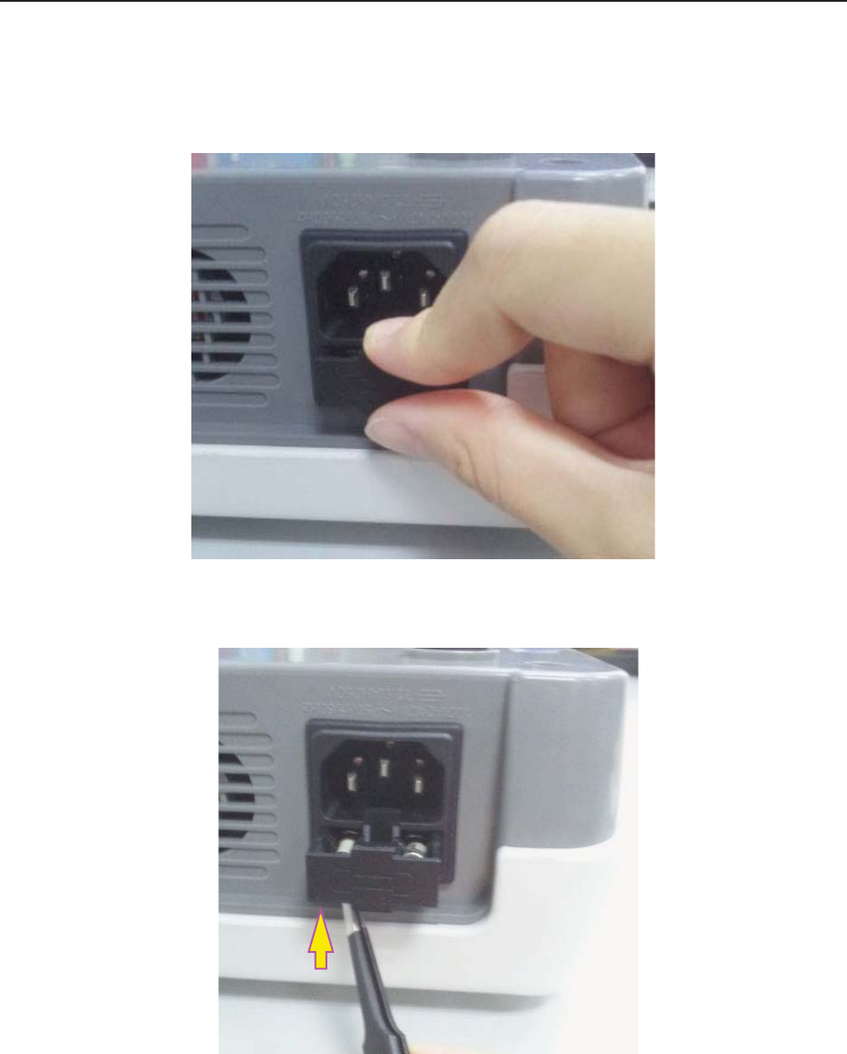
F Series Fetal & Maternal Monitor User Manual Ultrasound Intensity and Safety
- 159 -
To replace a fuse:
1) Place the base station on a flat surface and remove the power cord.
2) Reverse the base station and pull the fuse container out as far as it can go.
3) Use a screw driver or a pair of pliers to push the fuse up from the bottom of the
container.
4) Take the fuse out and replace it with a new one that is supplied by the manufacturer or
of the same specifications.
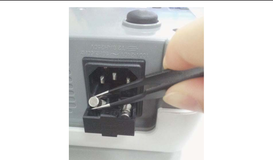
F Series Fetal & Maternal Monitor User Manual Ultrasound Intensity and Safety
- 160 -
5) Push the fuse container all the way back in position.

F Series Fetal & Maternal Monitor User Manual Ultrasound Intensity and Safety
- 161 -
Appendix 4 Ultrasound Intensity and Safety
A4.1 Ultrasound in Medicine
The use of diagnostic ultrasound has proved to be a valuable tool in medical practice. Given its
known benefits for non-invasive investigations and medical diagnosis, including investigation of
the human fetus, the question of clinical safety with regards to ultrasound intensity arises.
There is no easy answer to the question of safety surrounding the use of diagnostic ultrasound
equipment. Application of the ALARA (As Low As Reasonably Achievable) principle serves as a
rule-of-thumb that will help you to get reasonable results with the lowest possible ultrasonic
output.
The American Institute of Ultrasound in Medicine (AIUM) states that given its track record of
over 25 years of use and no confirmed biological effects on patients or instrument operators, the
benefits of the prudent use of diagnostic ultrasound clearly outweigh any risks.
A4.2 Ultrasound Safety and the ALARA Principle
Ultrasound waves dissipate energy in the form of heat and can therefore cause tissue warming.
Although this effect is extremely low with Doppler, it is important to know how to control and
limit patient exposure. Major governing bodies in ultrasound have issued statements to the effect
that there are no known adverse effects from the use of diagnostic ultrasound, however, exposure
levels should always be limited to As Low As Reasonably Achievable (the ALARA principle).
A4.3 Explanation of MI/TI
A4.3.1 MI (Mechanical Index)
Cavitations will be generated when ultrasound wave passes through and contacts tissues,
resulting in instantaneous local overheating. This phenomenon is determined by acoustic pressure,
spectrum, focus, transmission mode, and factors such as states and properties of the tissue and
boundary. This mechanical bioeffect is a threshold phenomenon that occurs when a certain level
of ultrasound output is exceeded. The threshold is related to the type of tissue. Although no
confirmed adverse mechanical effects on patients or mammals caused by exposure at intensities
typical of present diagnostic ultrasound instruments have ever been reported, the threshold for
cavitation is still undetermined. Generally speaking, the higher the acoustic pressure, the greater
the potential for mechanical bioeffects; the lower the acoustic frequency, the greater the potential
for mechanical bioeffects.
The AIUM and NEMA formulate mechanical index (MI) in order to indicate the potential for
mechanical effects. The MI is defined as the ratio of the peak-rarefactional acoustic pressure
(should be calculated by tissue acoustic attenuation coefficient 0.3dB/cm/MHz) to the acoustic
frequency.

F Series Fetal & Maternal Monitor User Manual Ultrasound Intensity and Safety
- 162 -
MI = Pr, ǩ
fawf CMI
CMI = 1 (MPa / MHz )
A4.3.2 TI (Thermal Index)
Heating of tissues is caused by absorption of ultrasound when the ultrasound energy is applied.
The temperature rise is determined by the acoustic intensity, exposed area and thermophysical
properties of the tissue.
In order to indicate the potential for temperature rise caused by thermal effects, the AIUM and
NEMA formulate thermal index (TI). It is defined as the ratio of the total acoustic power to the
acoustic power required to raise the tissue temperature by 1ºC (1.8ºF).
According to different thermophysical properties of the tissue, TI is divided into three kinds: TIS,
TIB and TIC.
TIS (Soft Tissue Thermal Index): It provides an estimate of potential temperature rise in soft or
similar tissues.
TIB (Bone Thermal Index): It provides an estimate of potential temperature rise when the
ultrasound beam passes through soft tissue and a focal region is in the immediate vicinity of
bone.
TIC (Cranial Bone Thermal Index): It provides an estimate of potential temperature rise in the
cranial bones or superficial bones.
A4.3.3 Measurement Uncertainty
The uncertainties in the measurements were predominantly systematic in origin; the random
uncertainties were negligible in comparison. The overall systematic uncertainties were
determined as follows:
1. Hydrophone Sensitivity
Based on the HNP-0400 hydrophone calibration certificate, the hydrophone measurement
uncertainty for 1-15MHz is 1 dB, which is equivalent to an uncertainty of ±12.20% for intensity
and ±6.10% for pressure. This uncertainty is used in PW measurement uncertainty assessment.
2. Digitizer
Based on the oscilloscope calibration certificate, the oscilloscope uncertainty is ±1.16% for
intensity and ±0.58% for pressure.
3. Temperature
Based on the temperature variation of the water bath, the uncertainty is ±1.6% for intensity and
±0.8% for pressure.
4. Spatial Averaging
±10.2% for intensity, and ±6.1% for pressure.
5. Non-linear Distortion:
N/A. No effects of nonlinear propagation were observed.
Since all the above error sources are independent, they may be added on an RMS basis, giving a
total uncertainty of ± 26.62 percent for all intensity values reported, ± 13.31 percent for all the

F Series Fetal & Maternal Monitor User Manual Ultrasound Intensity and Safety
- 163 -
pressure values and ± 14.52 percent for the Mechanical Index.
A4.4 Prudent Use Statement
Although no confirmed bioeffects on patients caused by exposure from present diagnostic
ultrasound equipment have ever been reported, the potential exists that such bioeffects may be
identified in the future. Therefore, the ultrasound should be used prudently. High levels of
acoustic output and long exposure time should be avoided while acquiring necessary clinical
information.
A4.5 References for Acoustic Output and Safety
1. “Bioeffects and Safety of Diagnostic Ultrasound” issued by AIUM in 1993
2. “Medical Ultrasound Safety” issued by AIUM in 1994
3. "Acoustic Output Measurement Standard for Diagnostic Ultrasound Equipment,
Revision 3" issued by AIUM/NEMA in 2004
4. "Standard for real-time display of thermal and mechanical acoustic output indices on
diagnostic ultrasound equipment, Revision 2" issued by AIUM/NEMA in 2004
5. "Information for Manufacturers Seeking Marketing Clearance of Diagnostic
Ultrasound Systems and Transducers" issued in 2008.
6. “Medical electrical equipment—Part 2-37: Particular requirements for the basic safety and
essential performance of ultrasonic medical diagnostic and monitoring equipment" issued by
IEC in 2007.

F Series Fetal & Maternal Monitor User Manual Ultrasound Intensity and Safety
- 164 -
A4.6 Probe Acoustic Output Parameters List
A4.6.1 Test of Wired Probe
Acoustic Output Reporting Table (F9/F9 Express)
Operating Mode: PW mode
Working Frequency: 1.0MHz
Index Label MI
TIS TIB
TIC
Scan Non-scan
Non-scan
Aaprt1 Aaprt>1
Global Maximum Index Value 0.01567 0.008761 0.05723 N/A
Associated
Acoustic
Parameters
Pr.a (MPa) 0.01567
P (mW) 11.52 N/A
Min of [Pa(Zs),Ita.a(Zs)] (mW) 1.84
Zs (cm) 13.95
Zbp (cm) 5.188
Zb (cm) 13.60
Z at max Ipi.a (cm) 13.80 13.80
deq(Zb) (cm) 1.75
fawf (MHz) 1.00 1.00 1.00 N/A
Dim of Aaprt X (cm) ĭ3.46 ĭ3.46 N/A
Y (cm) ĭ3.46 ĭ3.46 N/A
Other
Information
td (usec) 88.72
prr (Hz) 2000
Pr at max Ipi (MPa) 0.02930
Deq at max Ipi (cm) 1.73
Ipi.3 at max MI (W/cm2) 0.01025
Focal
Length
Flx (cm) N/A
Fly (cm) N/A
Operating
Control
Conditions
Focus(mm) Fixed
Depth(mm) Fixed
Freq(MHz) 1.0

F Series Fetal & Maternal Monitor User Manual Ultrasound Intensity and Safety
- 165 -
Operating Mode: PW mode
Working Frequency: 1.0MHz
Acoustic Output MI Ispta.3
(mW/cm2)
Isppa.3
(W/cm2)
Global Maximum Value 0.01567 1.817 0.01025
Associated Acoustic
Parameter
Pr.3 (MPa) 0.01567
W0 (mW) 11.52 11.52
fc (MHz) 1.00 1.00 1.00
Zsp (cm) 13.65 13.65 13.65
Beam
dimensions
X-6 (cm) 0.5795 0.5795
Y-6 (cm) 0.6061 0.6061
PD (usec) 88.72 88.72
PRF (Hz) 2000 2000
EDB Az (cm) ĭ3.46
Ele (cm) ĭ3.46
Operating Control
Conditions Fixed

F Series Fetal & Maternal Monitor User Manual Ultrasound Intensity and Safety
- 166 -
Acoustic Output Reporting Table (F6/F6 Express)
Operating Mode: PW mode
Working Frequency: 1.0MHz
Index Label MI
TIS TIB
TIC
Scan
Non-scan
Non-sca
n
Aaprt
1 Aaprt>1
Global Maximum Index Value 0.01405 0.006149 0.04687 N/A
Associated
Acoustic
Parameters
Pr.a (MPa) 0.01405
P (mW) 10.70 N/A
Min of [Pa(Zs),Ita.a(Zs)] (mW) 1.29
Zs (cm) 13.45
Zbp (cm) 4.236
Zb (cm) 13.35
Z at max Ipi.a (cm) 13.45 13.45
deq(Zb) (cm) 2.04
fawf (MHz) 1.00 1.00 1.00 N/A
Dim of Aaprt X (cm) ĭ2.83 ĭ2.83 N/A
Y (cm) ĭ2.83 ĭ2.83 N/A
Other
Information
td (usec) 89.36
prr (Hz) 2000
Pr at max Ipi (MPa) 0.0229
Deq at max Ipi (cm) 2.04
Ipi.3 at max MI (W/cm2) 0.007225
Focal
Length
Flx (cm) N/A
Fly (cm) N/A
Operating
Control
Conditions
Focus(mm) Fixed
Depth(mm) Fixed
Freq(MHz) 1.0

F Series Fetal & Maternal Monitor User Manual Ultrasound Intensity and Safety
- 167 -
Operating Mode: PW mode
Working Frequency: 1.0MHz
Acoustic Output MI Ispta.3
(mW/cm2)
Isppa.3
(W/cm2)
Global Maximum Value 0.01405 1.288 0.007225
Associated Acoustic
Parameter
Pr.3 (MPa) 0.01405
W0 (mW) 10.70 10.70
fc (MHz) 1.00 1.00 1.00
Zsp (cm) 13.30 13.30 13.30
Beam
dimensions
X-6 (cm) 0.7092 0.7092
Y-6 (cm) 0.7766 0.7766
PD (usec) 89.36 89.36
PRF (Hz) 2000 2000
EDB Az (cm) ĭ2.83
Ele (cm) ĭ2.83
Operating Control
Conditions Fixed

F Series Fetal & Maternal Monitor User Manual Abbreviation
- 168 -
A4.6.2 Test of Wireless Probe (FTS-3)
Acoustic Output Reporting Table
Operating Mode: PW mode
Working Frequency: 1.0MHz
Index Label MI
TIS TIB
TIC
Scan Non-scan
Non-scan
Aaprt1 Aaprt>1
Global Maximum Index Value 0.01087 0.002949 0.01939 N/A
Associated
Acoustic
Parameters
Pr.a (MPa) 0.01087
P (mW) 3.496 N/A
Min of [Pa(Zs),Ita.a(Zs)] (mW) 0.62
Zs (cm) 12.50
Zbp (cm) 5.188
Zb (cm) 11.95
Z at max Ipi.a (cm) 12.10 12.10
deq(Zb) (cm) 1.77
fawf (MHz) 1.00 1.00 1.00 N/A
Dim of Aaprt X (cm) ĭ3.46 ĭ3.46 N/A
Y (cm) ĭ3.46 ĭ3.46 N/A
Other
Information
td (usec) 90.65
prr (Hz) 2000
Pr at max Ipi (MPa) 0.01743
Deq at max Ipi (cm) 1.74
Ipi.3 at max MI (W/cm2) 0.003412
Focal
Length
Flx (cm) N/A
Fly (cm) N/A
Operating
Control
Conditions
Focus(mm) Fixed
Depth(mm) Fixed
Freq(MHz) 1.0

F Series Fetal & Maternal Monitor User Manual Abbreviation
- 169 -
Operating Mode: PW mode
Working Frequency: 1.0MHz
Acoustic Output MI Ispta.3
(mW/cm2)
Isppa.3
(W/cm2)
Global Maximum Value 0.01087 0.6186 0.003412
Associated Acoustic
Parameter
Pr.3 (MPa) 0.01087
W0 (mW) 3.496 3.496
fc (MHz) 1.00 1.00 1.00
Zsp (cm) 11.80 11.80 11.80
Beam
dimensions
X-6 (cm) 0.5663 0.5663
Y-6 (cm) 0.5437 0.5437
PD (usec) 90.65 90.65
PRF (Hz) 2000 2000
EDB Az (cm) ĭ3.46
Ele (cm) ĭ3.46
Operating Control
Conditions Fixed

F Series Fetal & Maternal Monitor User Manual Abbreviation
- 170 -
Appendix 5 Abbreviation
The abbreviations used in this manual and their full names are listed below:
Abbreviation Full Name
AC Alternative Current
AFM Automatic Fetal Movement [Detection]
BPM Beat(s) Per Minute
CTG Cardiotocography
DC Direct Current
DECG Direct ECG
DFHR Direct FHR
DIA Diastolic Blood Pressure
ECG Electrocardiogram
FH Fetal Heart
FHR Fetal Heart Rate
FM Fetal Movement
FS Fetal Stimulator
HR Heart Rate
ICU Intensive Care Unit
ID Identity
IUP Intra-Uterine Pressure
IUPC Intra-Uterine Pressure Catheter
LCD Liquid Crystal Display
MAP Mean Artery Blood Pressure
MECG Maternal ECG
MFM Manual Fetal Movement [Detection]
MRI Magnetic Resonance Imaging
NIBP Non-Invasive Blood Pressure
NST Non Stress Test
PR Pulse Rate
SOV Signals Overlap Verification
SpO2 Pulse Oximetry

F Series Fetal & Maternal Monitor User Manual Abbreviation
- 171 -
STV Short-Term Variation
SYS Systolic Blood Pressure
TEMP Temperature
TOCO Tocotonometer
UA Uterine Activity [TOCO]
US Ultrasound [Transducer]

F Series Fetal & Maternal Monitor User Manual Ordering Information
- 172 -
Appendix 6 Ordering Information
Accessories (standard and optional configuration) supplied or approved by the manufacturer can
be used with the monitor. See the following table for details. The accessories employed by us,
such as the rechargeable battery, are products having passed the authentication of CE, and they
have the characteristics specified by their manufacturers. The materials with which the patient
can come into contact conform to the standard of ISO 10993.
Accessory (Spare Part) Part Number
US Transducer 1 (purple label, for F9/F9 Express) 02.01.31528
US Transducer 2 (yellow label, for F9/F9 Express) 02.01.107705
US Transducer (pink label, for F6/F6 Express) 02.01.109301
Wireless US Transducer (American Standard) 02.01.000925
Wireless TOCO Transducer (American Standard) 02.01.000926
FTS-3 Overall Unit 83.62.001974
FTS-3 Overall Unit (Singleton Pregnancy) 83.62.002459
TOCO Transducer 02.01.31527
TOCO Transducer (IUP) 02.01.107791
Remote Event Marker 02.01.210095
Belt 01.57.471447
DECG Cable 01.13.036358
Disposable Fetal Spiral Electrode 01.57.02145
Disposable Attachment Pad Electrode 01.57.02146
IUP Cable 01.13.104152
IUP Connecting Cable 01.13.036357
Disposable Intrauterine Pressure Catheter 01.57.104153
3-lead ECG Cable (Grabber style, IEC) 01.57.471098
3-lead ECG Cable (Grabber style, AHA) 01.57.471095

F Series Fetal & Maternal Monitor User Manual Ordering Information
- 173 -
Disposable ECG Electrode (US) 01.57.471276
SpO2 Sensor 02.01.109069
NIBP Cuff (Upper Arm Perimeter 27cm-35cm, for Adult) 01.57.471330
NIBP Cuff Extension Tube 01.57.471005
TEMP Sensor 01.15.040187
Thermosensitive Recorder Paper (GE-American) 01.57.75111
Thermosensitive Recorder Paper (GE-International) 01.57.75112
Thermosensitive Recorder Paper (Philips-American) 01.57.75113
Thermosensitive Recorder Paper (Philips-International) 01.57.75114
Power Cord (American Standard) 21.13.036384
Fuse T2AH250V 21.21.064181
Rechargeable Lithium-ion Battery 21.21.064150
Rechargeable Lithium-ion Battery (FTS-3) 01.21.064143
CAUTION
Replacement of all above accessories can be performed by the operator. But only the
accessories supplied or recommended by the manufacturer are allowed connected to
the monitor.

F Series Fetal & Maternal Monitor User Manual EMC Information
- 174 -
Appendix 7 EMC Information
A7.1 Electromagnetic Emissions
Guidance and manufacture’s declaration – electromagnetic emission
The F Series Fetal & maternal Monitor is intended for use in the electromagnetic environment
specified below. The customer of the user of the F Series Fetal & maternal Monitor should assure
that it is used in such and environment.
Emission test Compliance Electromagnetic environment – guidance
RF emissions
CISPR 11 Group 1
The F Series Fetal & maternal Monitor uses RF
energy only for its internal function. Therefore,
its RF emissions are very low and are not likely
to cause any interference in nearby electronic
equipment.
RF emission
CISPR 11 Class A The F Series Fetal & maternal Monitor is
suitable for use in all establishments, other than
domestic and those directly connected to the
public low-voltage power supply network that
supplies buildings used for domestic purposes.
Harmonic emissions
IEC 61000-3-2 Class A
Voltage fluctuations/
flicker emissions
IEC 61000-3-3
Complies

F Series Fetal & Maternal Monitor User Manual EMC Information
- 175 -
A7.2 Electromagnetic Immunity
Guidance and manufacture’s declaration – electromagnetic immunity
The F Series Fetal & maternal Monitor is intended for use in the electromagnetic environment
specified below. The customer or the user of F Series Fetal & maternal Monitor should assure that it
is used in such an environment.
Immunity test IEC 60601 test
level Compliance level Electromagnetic environment
- guidance
Electrostatic
discharge (ESD)
IEC 61000-4-2
r 6 kV contact
r 8 kV air
r 6 kV contact
r 8 kV air
Floors should be wood,
concrete or ceramic tile. If floor
are covered with synthetic
material, the relative humidity
should be at least 30%.
Electrical fast
transient/burst
IEC 61000-4-4
r 2 kV for power
supply lines
r 1 kV for
input/output lines
r 2kV for power
supply lines
Not applicable
Mains power quality should be
that of a typical commercial or
hospital environment.
Surge
IEC 61000-4-5
r 1 kV line(s) to
line(s)
r 2 kV line(s) to
ground
r 1 kV differential
mode
r 2 kV common
mode
Mains power quality should be
that of a typical commercial or
hospital environment.
Power frequency
(50Hz/60Hz)
magnetic field
IEC61000-4-8
3 A/m 3 A/m
Power frequency magnetic
fields should be at levels
characteristic of a typical
location in a typical commercial
or hospital environment.

F Series Fetal & Maternal Monitor User Manual EMC Information
- 176 -
Voltage dips, short
interruptions and
voltage variations
on power supply
input lines
IEC 61000-4-11
< 5% UT
(> 95% dip in UT)
for 0.5 cycle
40% UT
(60% dip in UT)
for 5 cycles
70% UT
(30% dip in UT)
for 25 cycles
< 5% UT
(> 95% dip in UT)
for 5 sec
< 5% UT
(> 95% dip in UT)
for 0.5 cycle
40% UT
(60% dip in UT)
for 5 cycles
70% UT
(30% dip in UT)
for 25 cycles
< 5% UT
(> 95% dip in UT)
for 5 sec
Mains power quality should be
that of a typical commercial or
hospital environment. If the user
of the F Series Fetal & maternal
Monitor requires continued
operation during power mains
interruptions, it is recommended
that the F Series Fetal &
maternal Monitor be powered
from an uninterruptible power
supply or a battery.
NOTE: UT is the a.c. mains voltage prior to application of the test level.

F Series Fetal & Maternal Monitor User Manual EMC Information
- 177 -
A7.3 Electromagnetic Immunity
Guidance and manufacture’s declaration – electromagnetic immunity
The F Series Fetal & maternal Monitor is intended for use in the electromagnetic environment
specified below. The customer or the user of F Series Fetal & maternal Monitor should assure that it is
used in such an environment.
Immunity test IEC 60601 test
level
Compliance
level Electromagnetic environment - guidance
Conducted RF
IEC 61000-4-6
Radiated RF
IEC 61000-4-3
3 Vrms
150 kHz to 80 MHz
3 V/m
80 MHz to 2.5 GHz
3 Vrms
3 V/m
Portable and mobile RF communications
equipment should be used no closer to any
part of the F Series Fetal & maternal
Monitor including cables, than the
recommended separation distance
calculated from the equation applicable to
the frequency of the transmitter.
Recommended separation distance
Pd 2.1 150 kHz to 80 MHz
Pd 2.1 80 MHz to 800 MHz
Pd 3.2 800 MHz to 2.5 GHz
Where P is the maximum output power
rating of the transmitter in watts (W)
according to the transmitter manufacturer
and d is the recommended separation
distance in meters (m).
Field strengths from fixed RF transmitters,
as determined by an electromagnetic site
survey,a) should be less than the
compliance level in each frequency range.b)
Interference may occur in the vicinity of
equipment marked with the following
symbol:

F Series Fetal & Maternal Monitor User Manual EMC Information
- 178 -
NOTE 1: At 80 MHz and 800 MHz, the higher frequency range applies.
NOTE 2: These guidelines may not apply in all situations. Electromagnetic propagation is affected by
absorption and reflection from structures, objects and people.
a) Field strengths from fixed transmitters, such as base stations for radio (cellular/cordless) telephones
and land mobile radios, amateur radio, AM and FM radio broadcast and TV broadcast cannot be
predicted theoretically with accuracy. To assess the electromagnetic environment due to fixed RF
transmitters, an electromagnetic site survey should be considered. If the measured field strength in
the location in which the F Series Fetal & maternal Monitor is used exceeds the applicable RF
compliance level above, the F Series Fetal & maternal Monitor should be observed to verify normal
operation. If abnormal performance is observed, additional measures may be necessary, such as
reorienting or relocating the F Series Fetal & maternal Monitor.
b) Over the frequency range 150 kHz to 80 MHz, field strengths should be less than 3 V/m.

F Series Fetal & Maternal Monitor User Manual EMC Information
- 179 -
A7.4 Recommended Separation Distances
Recommended separation distances between
portable and mobile RF communications equipment and the
F Series Fetal & maternal Monitor
The F Series Fetal & maternal Monitor is intended for use in an electromagnetic environment in which
radiated RF disturbances are controlled. The customer or the user of the F Series Fetal & maternal
Monitor can help prevent electromagnetic interference by maintaining a minimum distance between
portable and mobile RF communications equipment (transmitters) and the F Series Fetal & maternal
Monitor as recommended below, according to the maximum output power of the communications
equipment.
Rated maximum
output power of
transmitter
(W)
Separation distance according to frequency of transmitter (m)
150 kHz to 80 MHz
Pd 2.1
80 MHz to 800 MHz
Pd 2.1
800 MHz to 2.5 GHz
Pd 3.2
0.01 0.12 0.12 0.23
0.1 0.38 0.38 0.73
1 1.2 1.2 2.3
10 3.8 3.8 7.3
100 12 12 23
For transmitters rated at a maximum output power not listed above, the recommended separation
distance d in meters (m) can be estimated using the equation applicable to the frequency of the
transmitter, where P is the maximum output power rating of the transmitter in watts (W) according to
the transmitter manufacturer.
NOTE 1: At 80 MHz and 800 MHz, the separation distance for the higher frequency range applies.
NOTE 2: These guidelines may not apply in all situations. Electromagnetic propagation is affected by
absorption and reflection from structures, objects and people.

F Series Fetal & Maternal Monitor User Manual Limitations of Ultrasonic Monitoring
- 180 -
Appendix 8 Limitations of Ultrasonic Monitoring
A8.1 How Does Ultrasound Work
When the ultrasound waves strike an object, they bounce back and create an echo. If the object
moves toward the sound source, the frequency of the echo increases. If the object moves away
from the sound source, the frequency of the echo decreases. This is called “Doppler Effect”. In
the 1960's, the ultrasonic technique was first applied to medical diagnostic imaging.
The ultrasound process involves placing a small device called a transducer, against the skin of the
patient near the region of interest. The ultrasound transducer combines functions of emitting and
receiving ultrasounds in one device. This transducer produces a stream of inaudible, high
frequency sound waves which penetrate into the body and bounce off the organs inside. It detects
sound waves as they bounce off or echo back from the internal structures and contours of the
organs. The movement of the organs produces the Doppler Effect, and this movement can be
measured and described by measuring the echo.
In fetal monitoring, the ultrasound transducer produces a stream of sound waves which penetrate
into the maternal abdomen and bounce off the fetal heart. Then the transducer receives the echoes
and transfers them to the monitor, which turns the signal into fetal heart beating sound and fetal
heart rate trace.
Therefore, placement of the transducer is critical to ultrasound fetal heart monitoring.
A8.2 Artifacts in Fetal Heart Monitoring
(1) How does artifact happen?
The transducer detects sound waves as they bounce off or echo back from the fetal heart.
However, the sound waves bouncing off from maternal blood vessels may be detected by the
transducer and then be processed by the monitor as well. As a result, artifacts may be produced.
The artifacts, if not correctly interpreted, may cause the physicians to perform unnecessary
interventions, or to fail to detect the fetal distress and the need for interventions.
The most common artifacts are doubling and halving.
(2) Doubling:
When the FHR drops to 120 bpm or lower, the diastole and systole become far apart, thereby the
monitor may mistake these two movements of a single heartbeat for two separate heartbeats. As a
result, a heart rate trace that is double the actual heart rate is produced. This often happens during
severe decelerations and bradycardia, representing an abrupt switch of the trace to double the
actual heart rate.
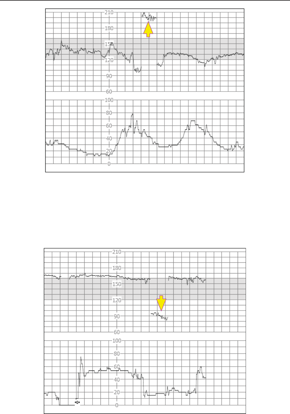
F Series Fetal & Maternal Monitor User Manual Limitations of Ultrasonic Monitoring
- 181 -
(3) Halving:
When the FHR increases to 180 bpm or higher, it is possible for the monitor to mistake the two
separate hearbeats for the diastole and systole of a single heartbeat. As a result, a heart rate trace
that is half the actual heart rate is produced. This often happens during tachycardia, representing
an abrupt switch of the trace to half the actual heart rate. The clinicians may interpret it as a
“deceleration”.
However, the heart beat sound from the monitor speaker is still reliable even when doubling or
halving is occurring.

F Series Fetal & Maternal Monitor User Manual Limitations of Ultrasonic Monitoring
- 182 -
Stethoscopy should be applied when sudden changes in baseline are detected.
If the amniotic membrane rupture and cervical dilatation are sufficient, consider using a spiral
electrode to obtain precise FHR with direct fetal ECG as the signal source.
(4) Erratic Traces / Drop out
When the fetal heart moves partially out of the ultrasound wave path, the transducer receives
mixed or weak signals, and thereby the monitor presents erratic traces. When the fetal heart
moves fully out of the path, inadequate consecutive and periodic signals are received, and no
trace is represented.
Erratic traces and transitory episodes of drop out are common, especially when the fetus or/and
mother move(s). If they exist for an extended period, it indicates that the transducer is not aimed
at the fetus. Repositioning of the transducer is needed.
A8.3 Audio Output and Screen Reading
In most instances, the audio output from the monitor speaker corresponds to the readings
presented on the monitor screen. But occasionally the fetal heart sound may differ from the trace
and numeric.
When the fetal heart moves partially out of the ultrasound wave path, the transducer receives
weaker FHR signal and other stronger signals (usually maternal heart/pulse rate). After the
signals are transmitted to the monitor, the audio system and the video system of the monitor
process the signals separately. On one hand, the audio circuit filters the low-frequency signals and
gives audio output of the high-frequency signals, so fetal heart sound is heard. On the other hand,
the autocorrelation algorithm computes the stronger signal source and thereby the maternal
heart/pulse rate is displayed. As a result, the audio output differs from the screen reading.
If this situation occurs, it can be dismissed by repositioning the transducer.
In a word, the abnormalities listed above (artifacts, sound and reading differences) are caused by
the limitations of ultrasonic monitoring technique. Fortunately they rarely occur. But a good
understanding of how to detect them and what countermeasures should be taken will help obtain
better fetal monitoring effect.
We hope you find this information useful. If you have any questions about fetal monitoring,
please contact our sales representatives and perinatal specialists.