EDAN INSTRUMENTS I15EDAN Blood Gas and Chemistry Analyzer User Manual
EDAN INSTRUMENTS, INC. Blood Gas and Chemistry Analyzer
UserManual.wiki
>
EDAN INSTRUMENTS
>
I15EDAN User Manual
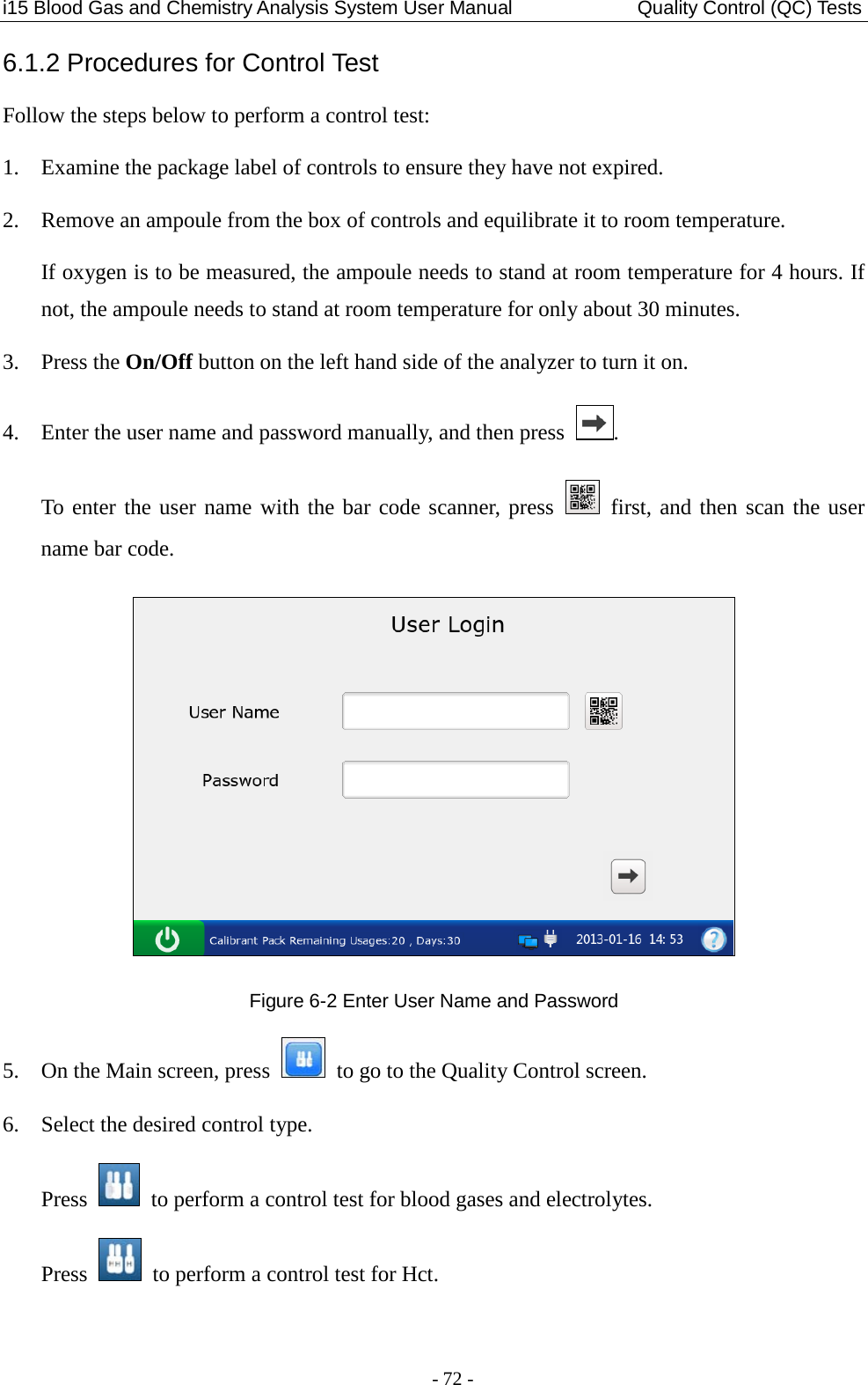
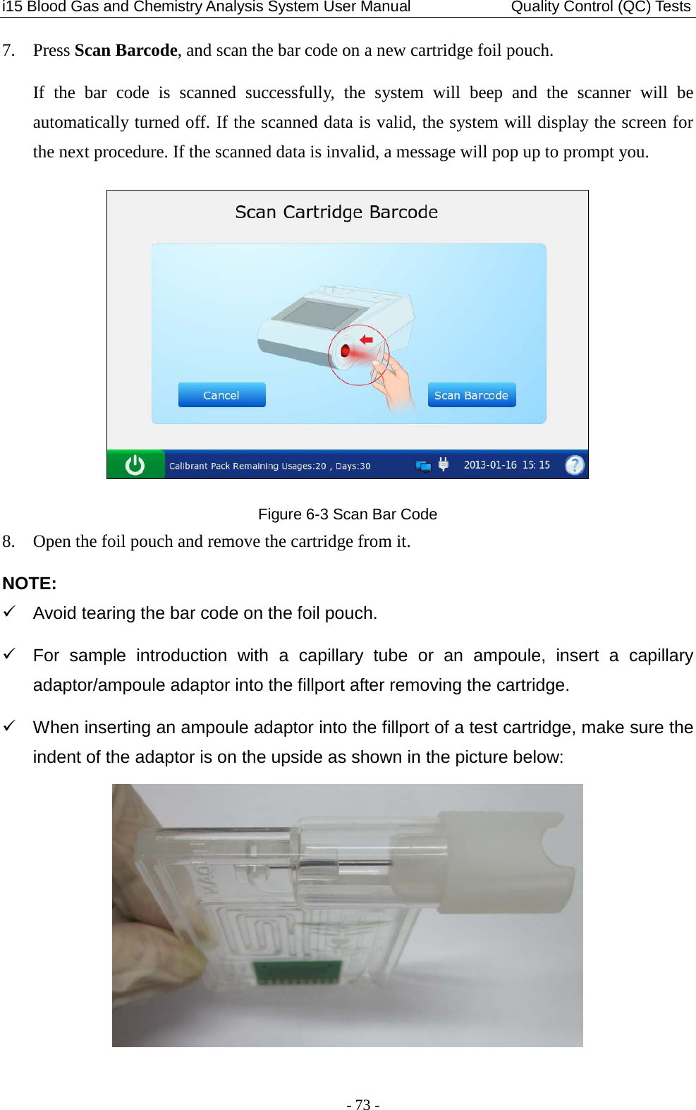
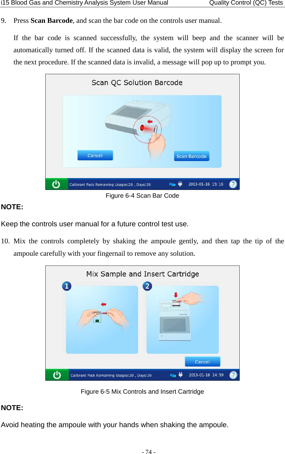
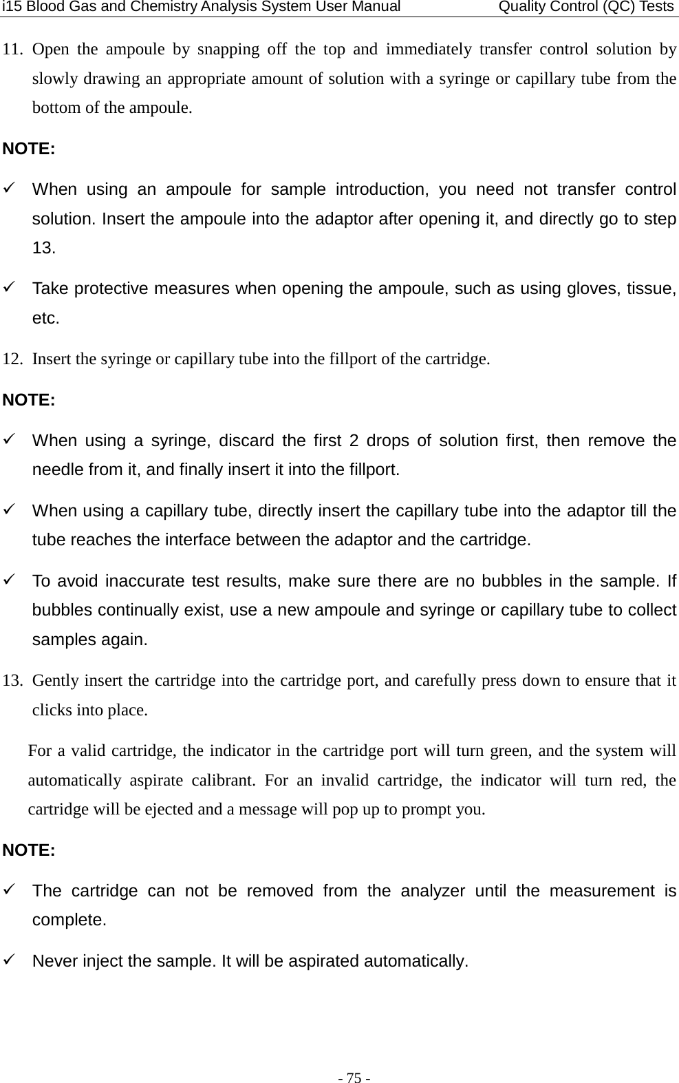
User Manual
Navigation menu
Upload a User Manual
Namespaces
Wiki Guide
HTML
PDF
Info
Views
User Manual
Discussion / Help
Navigation
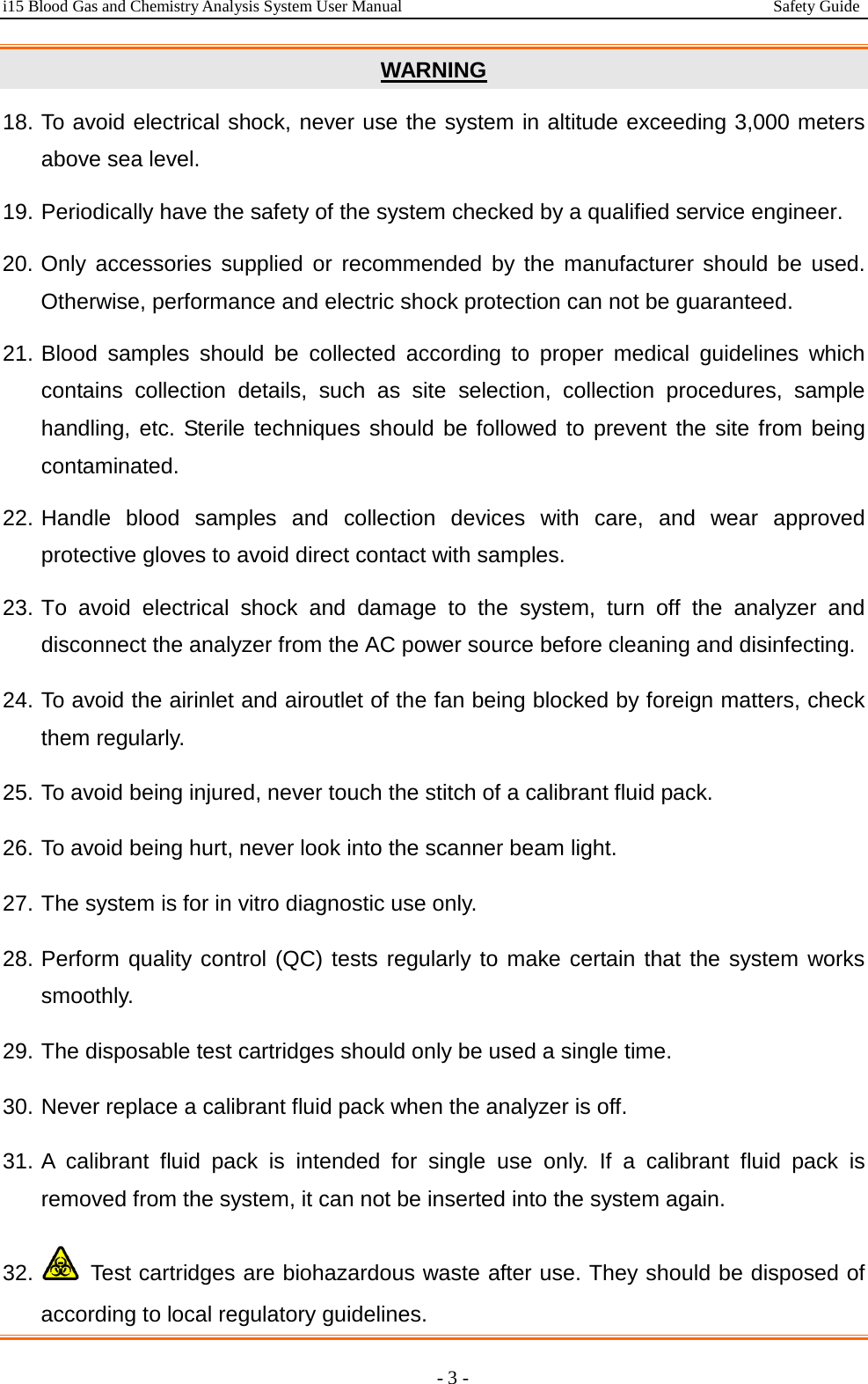
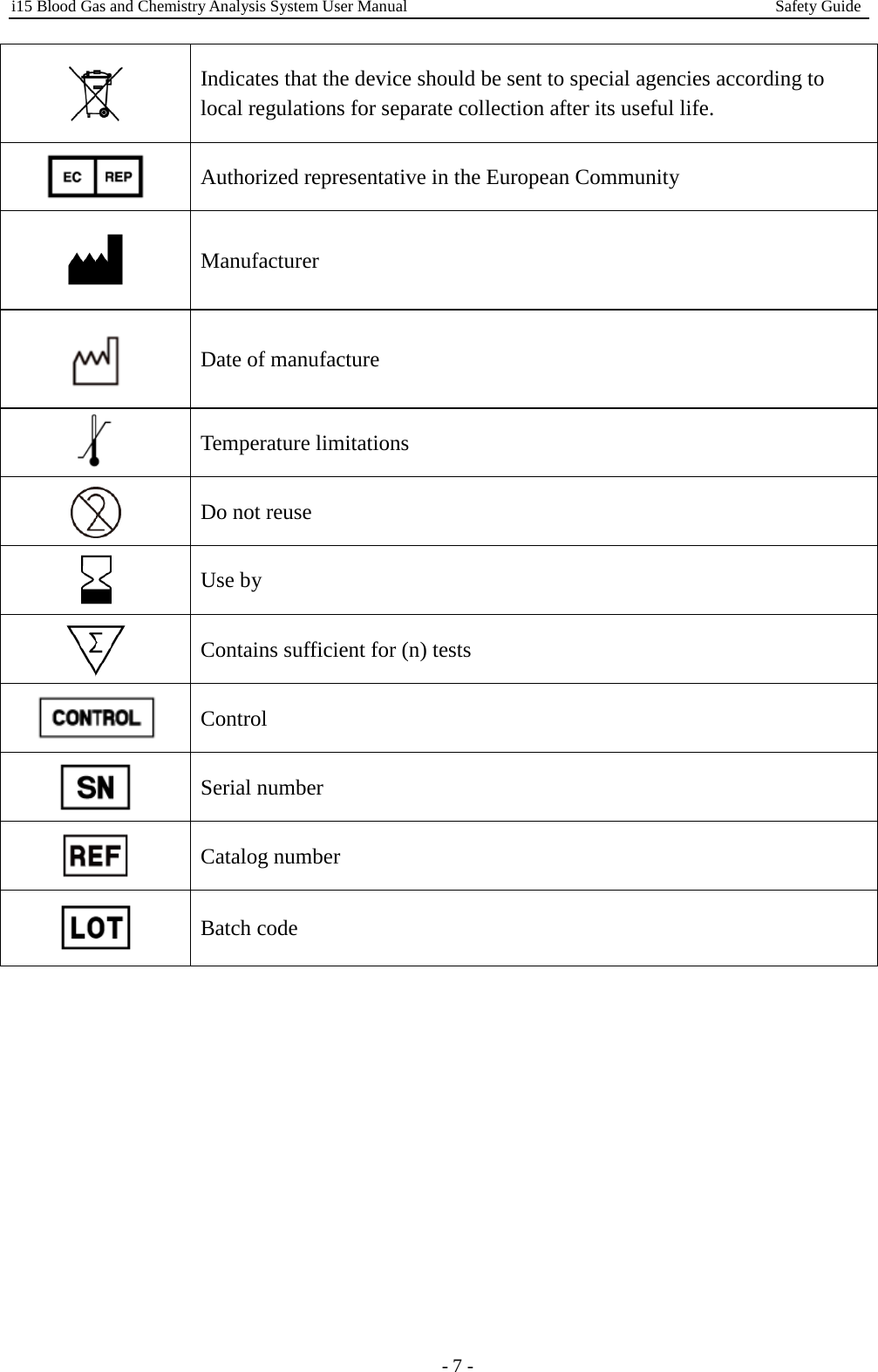
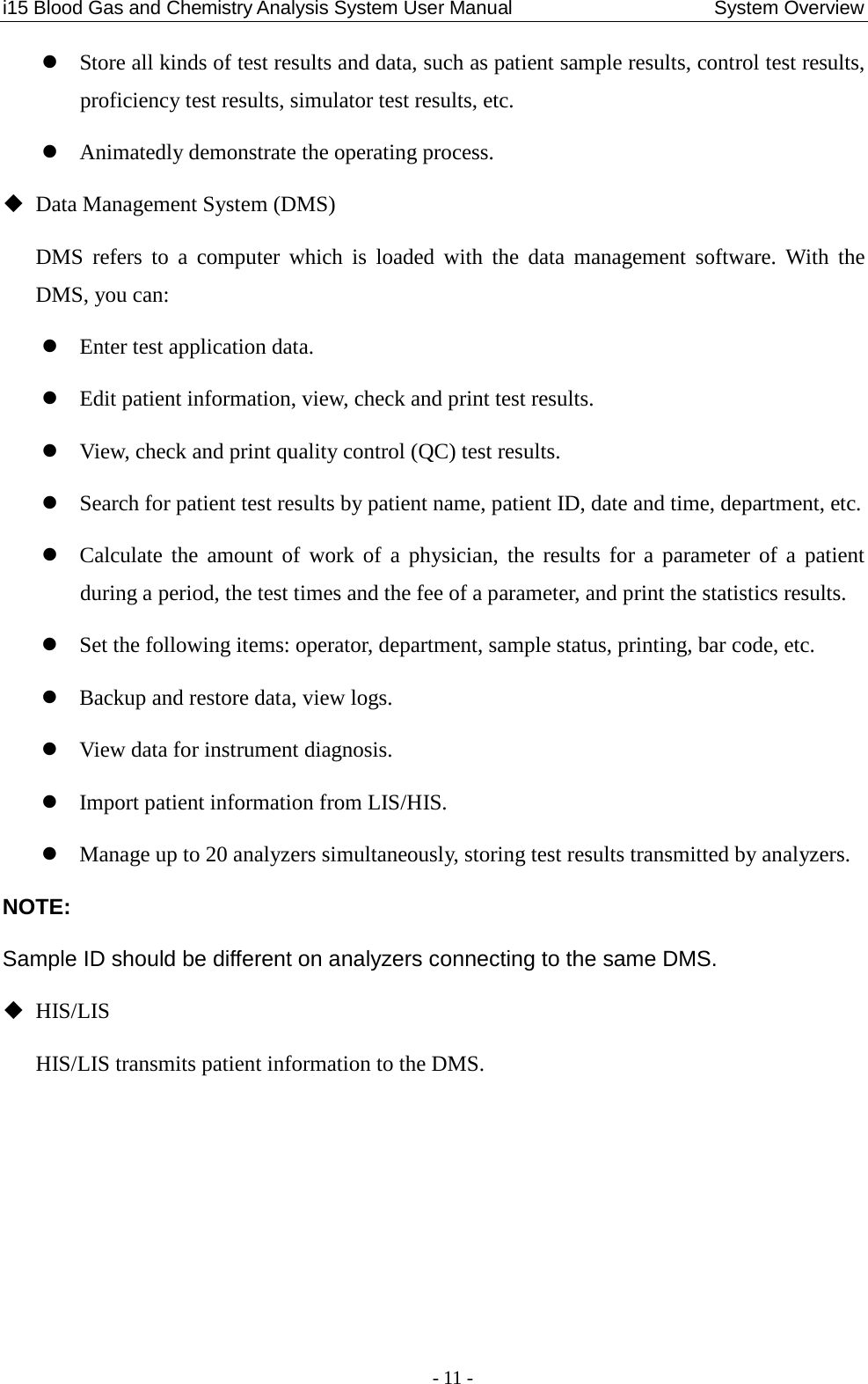
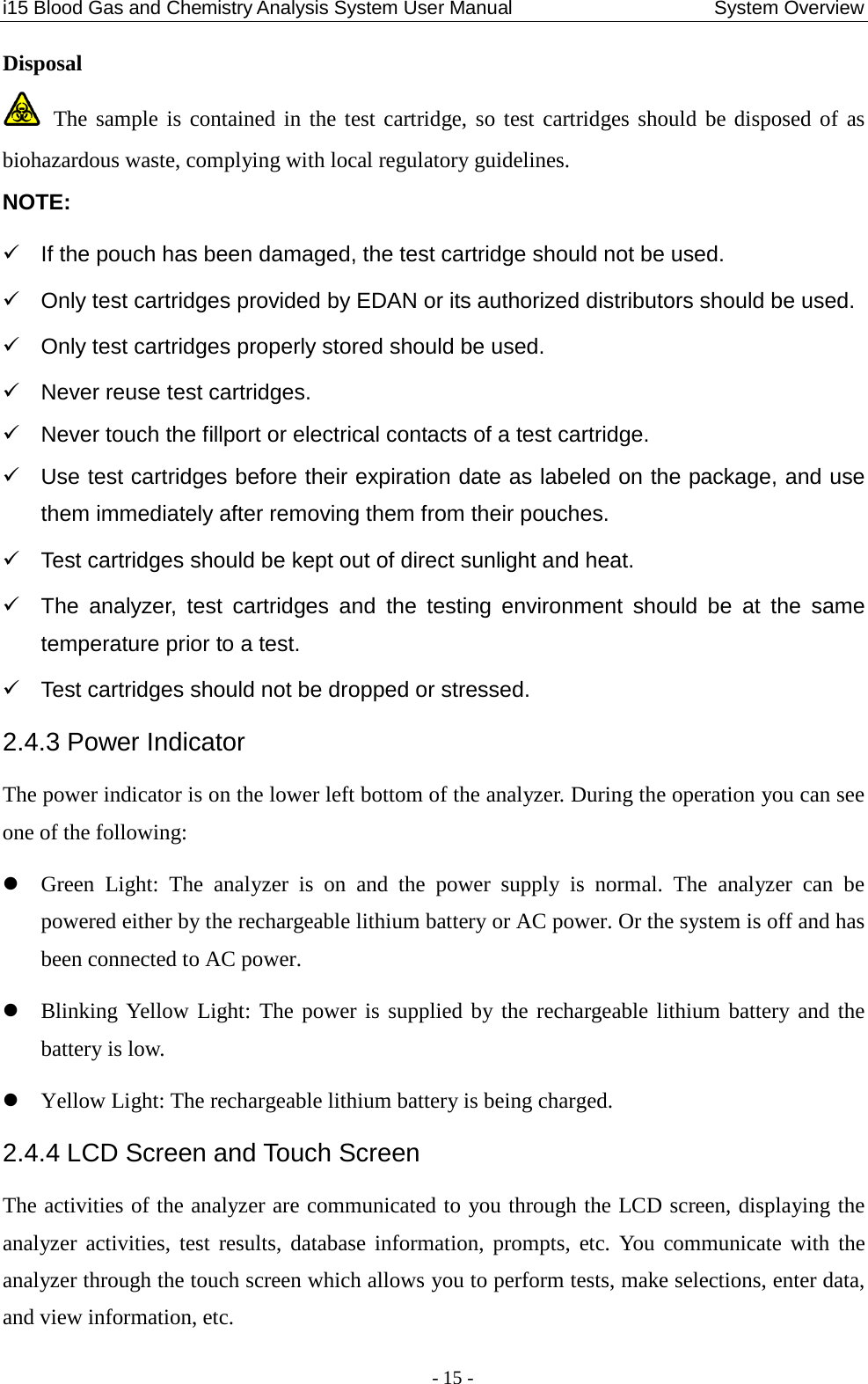
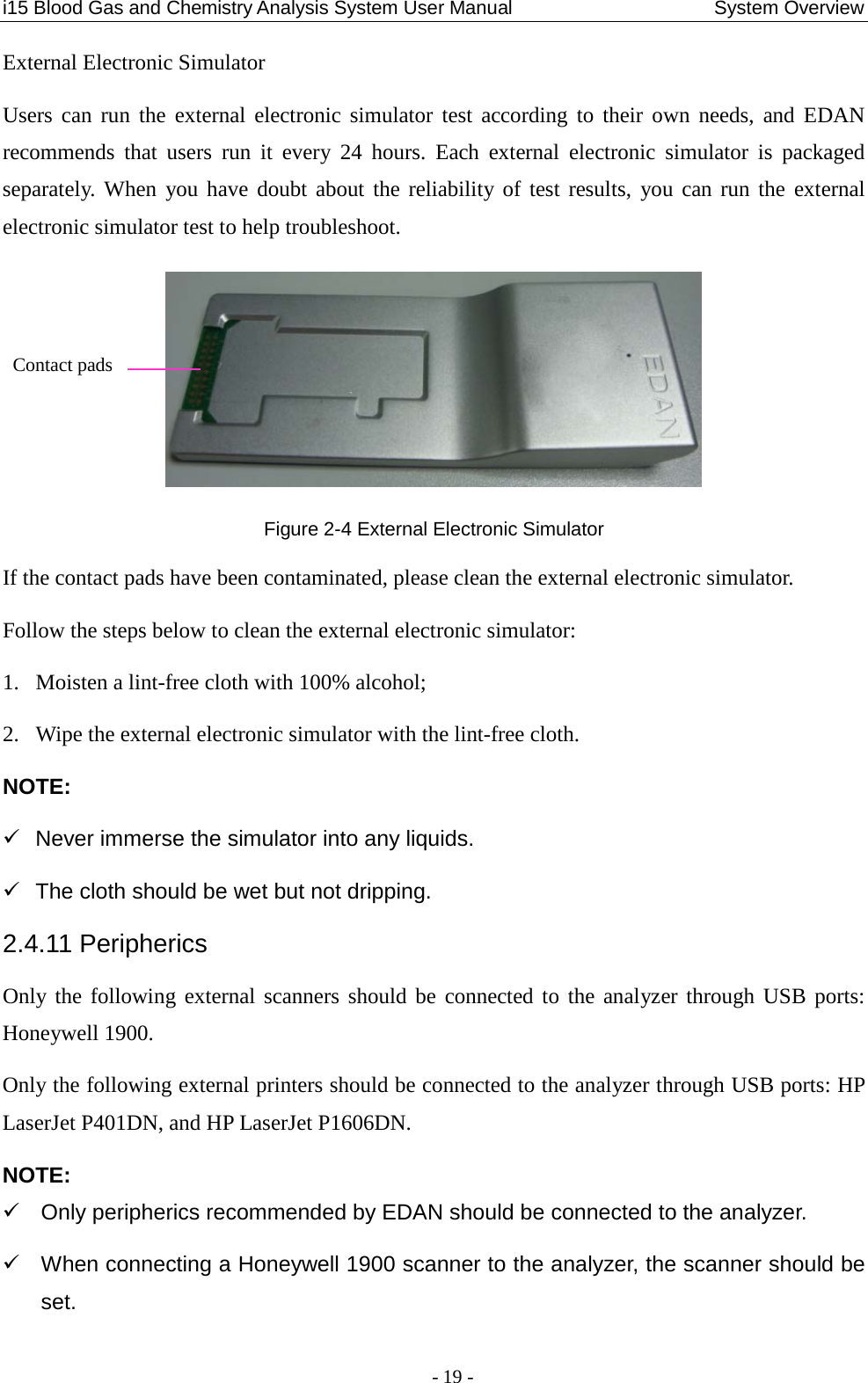
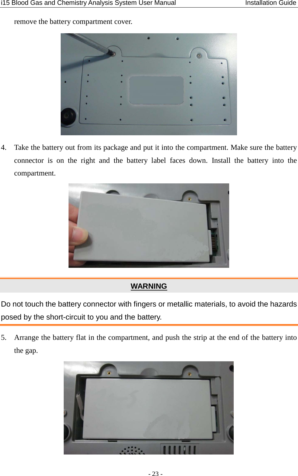
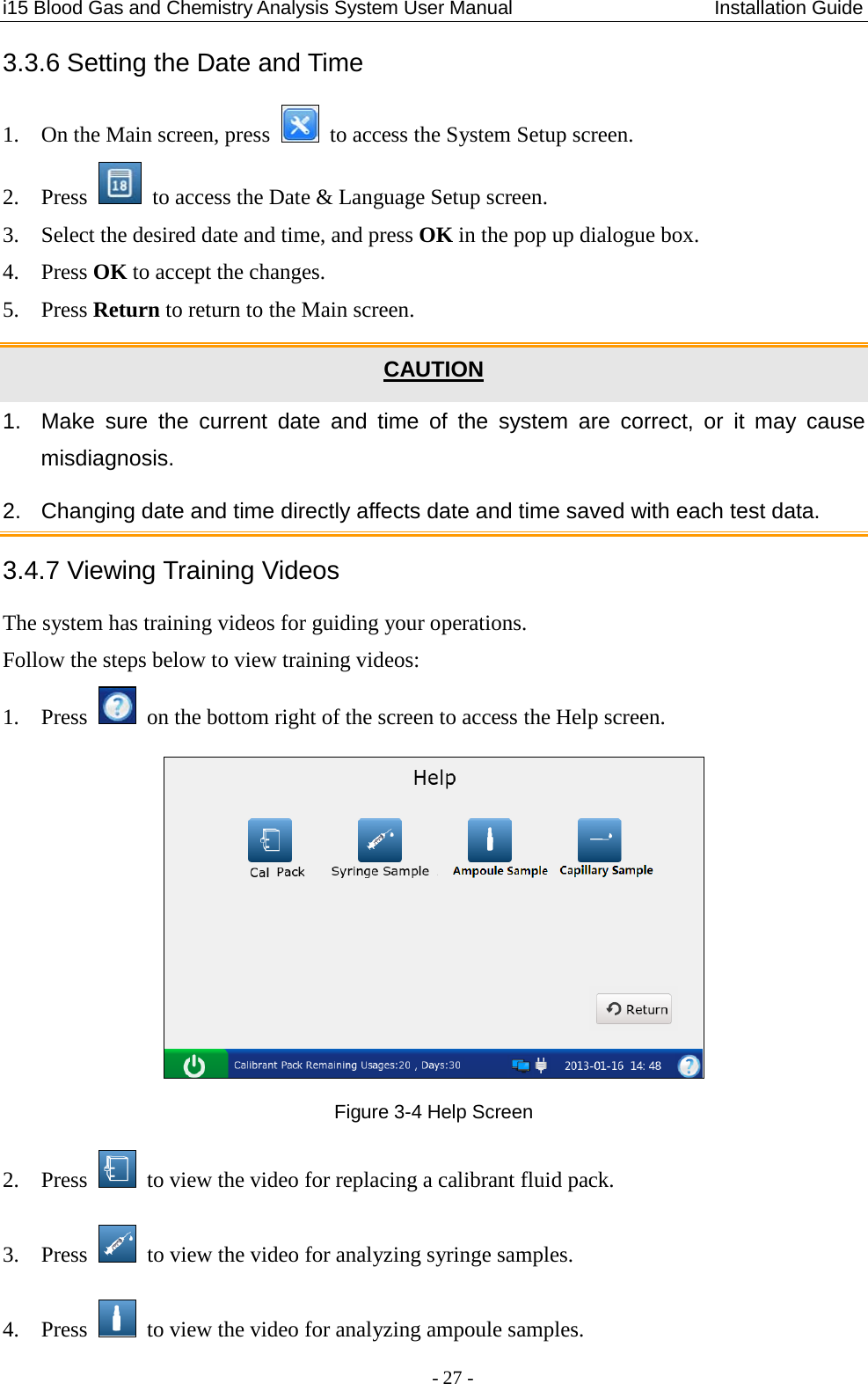
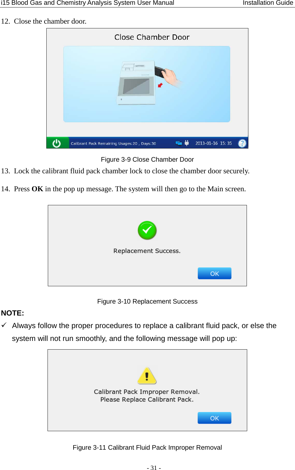
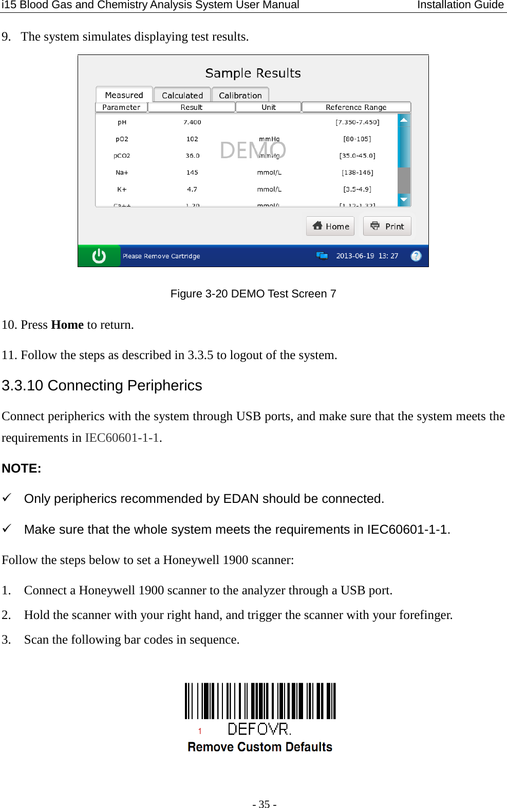
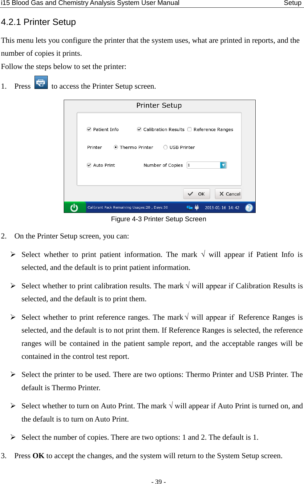
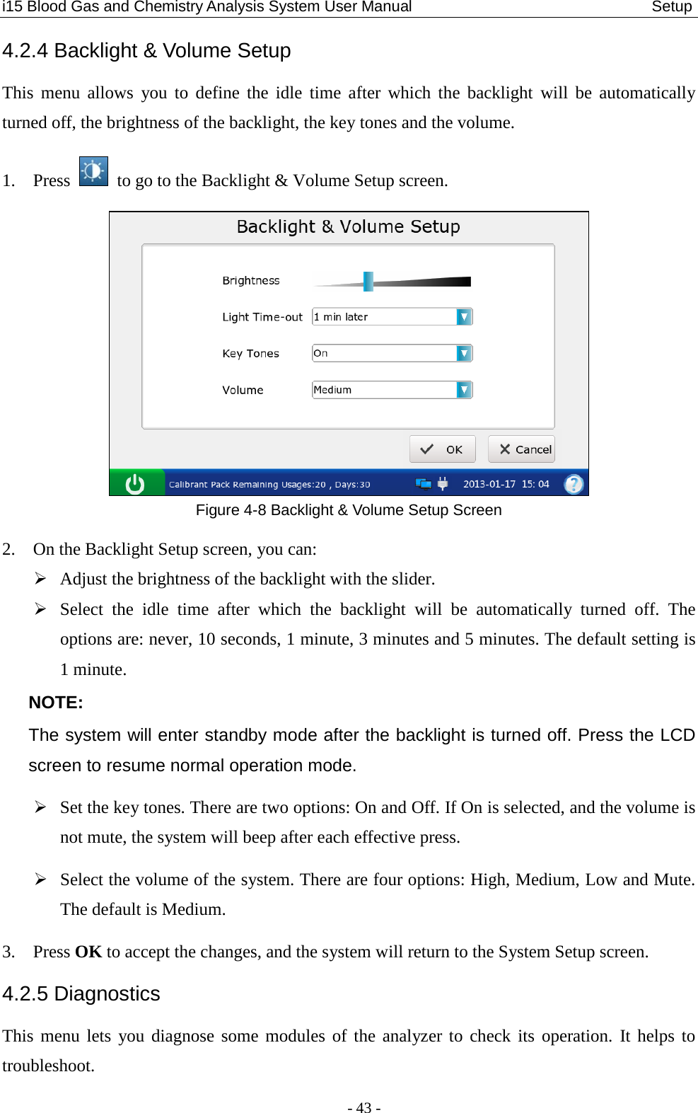
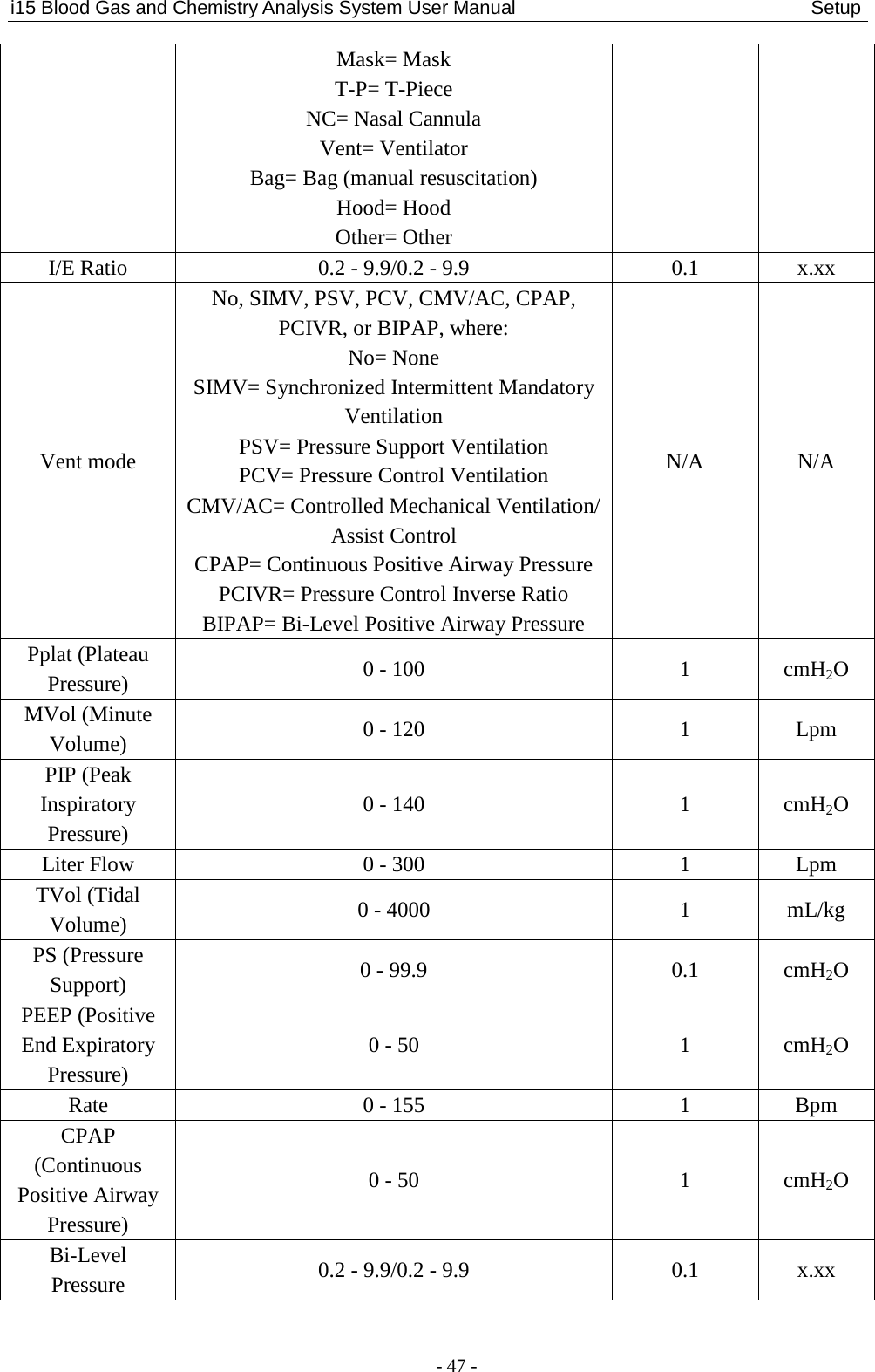
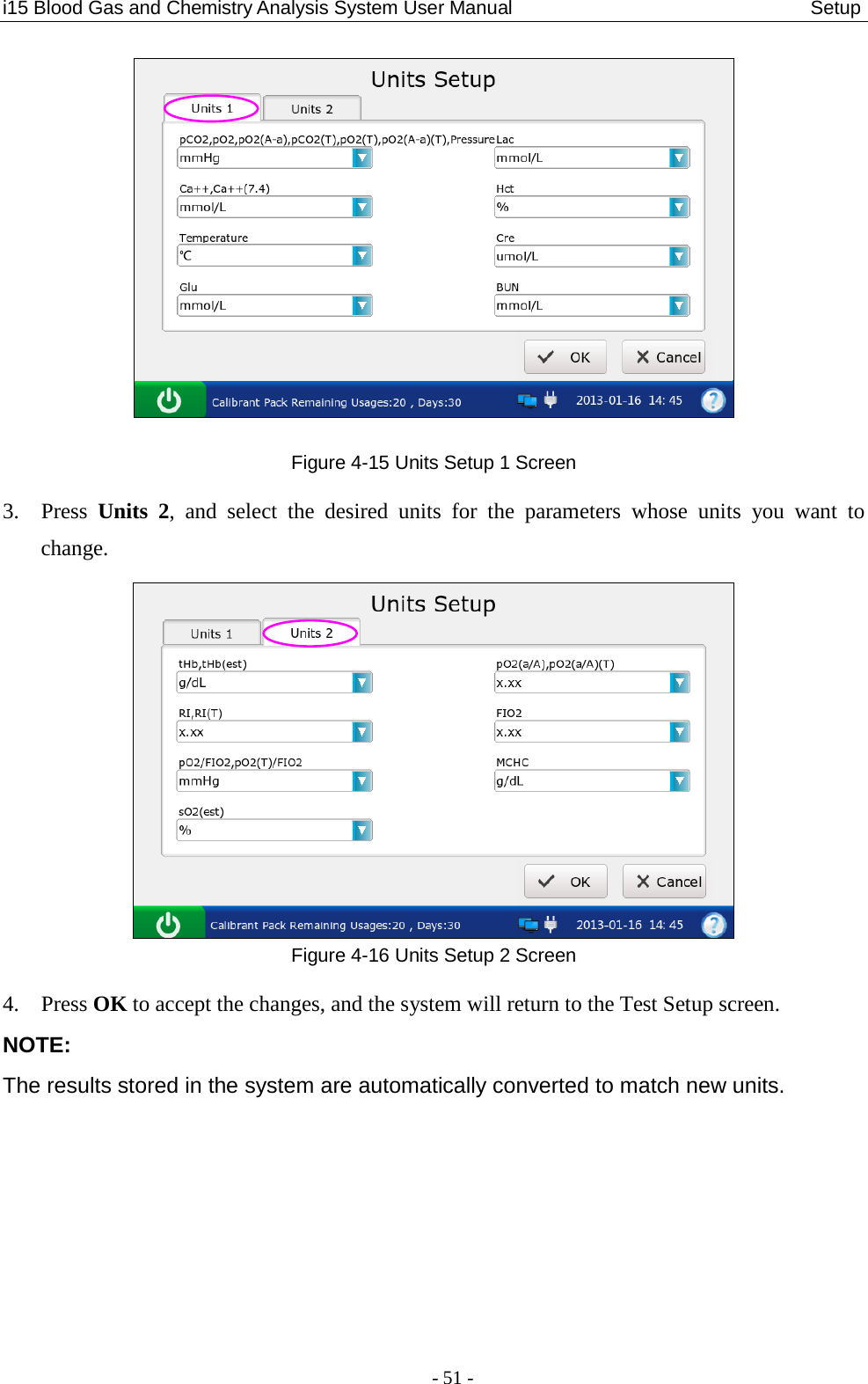
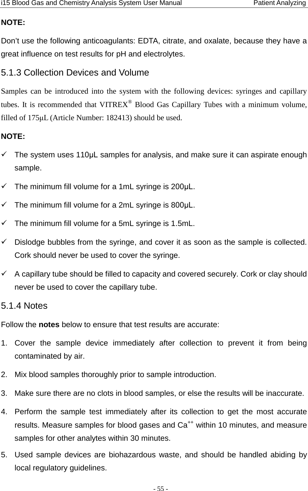
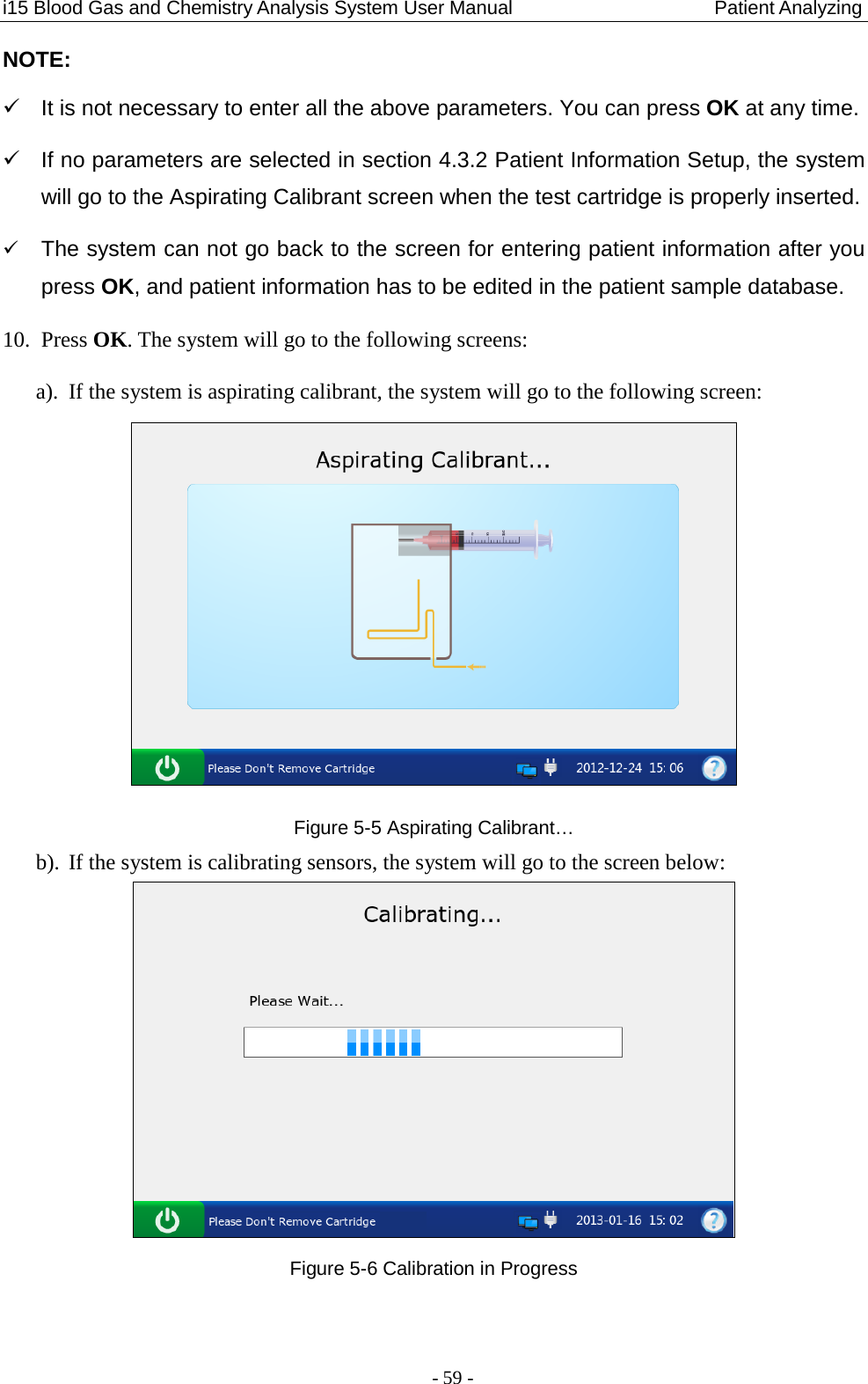
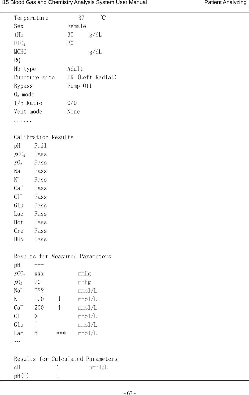
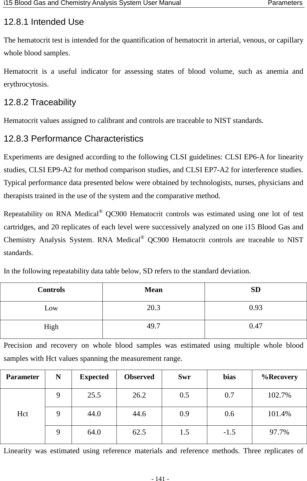
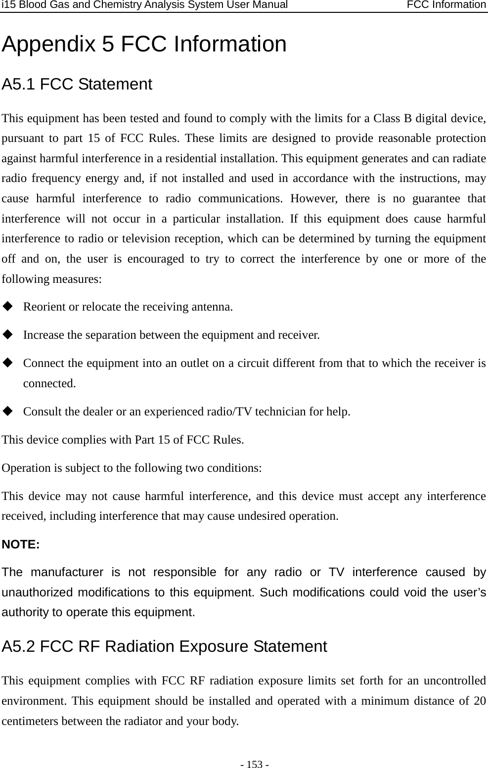
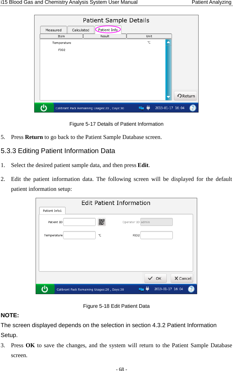
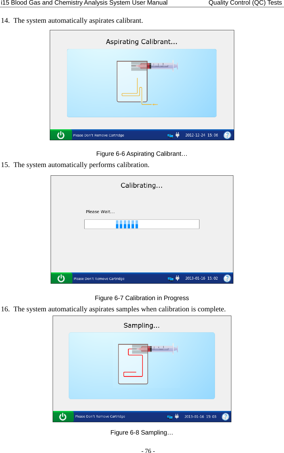
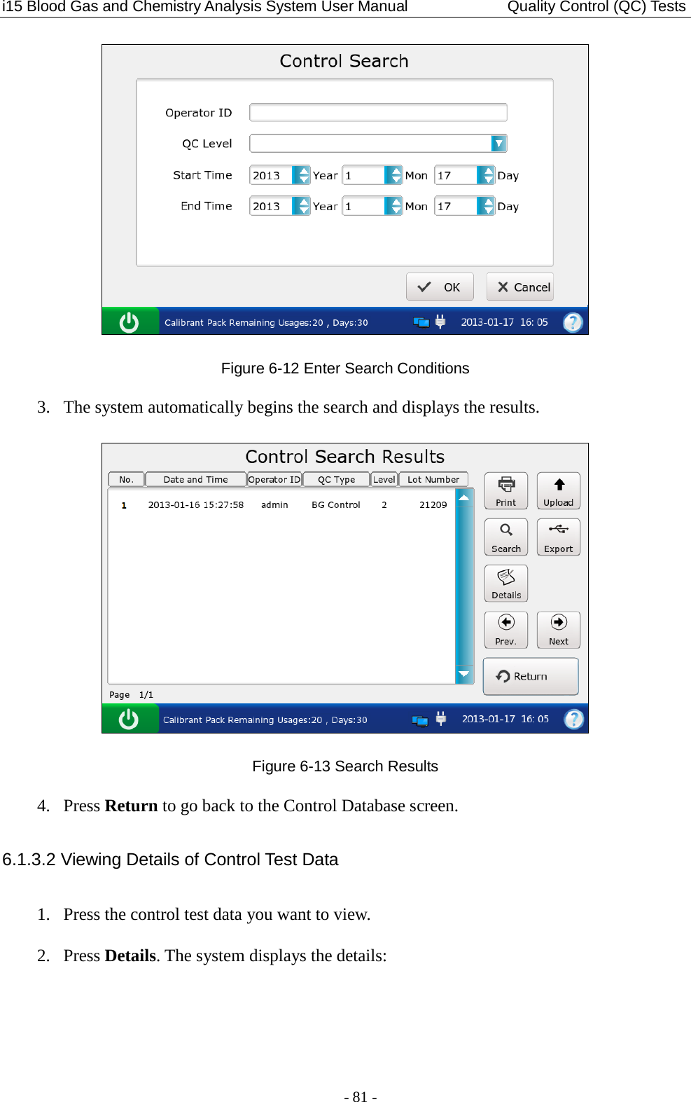
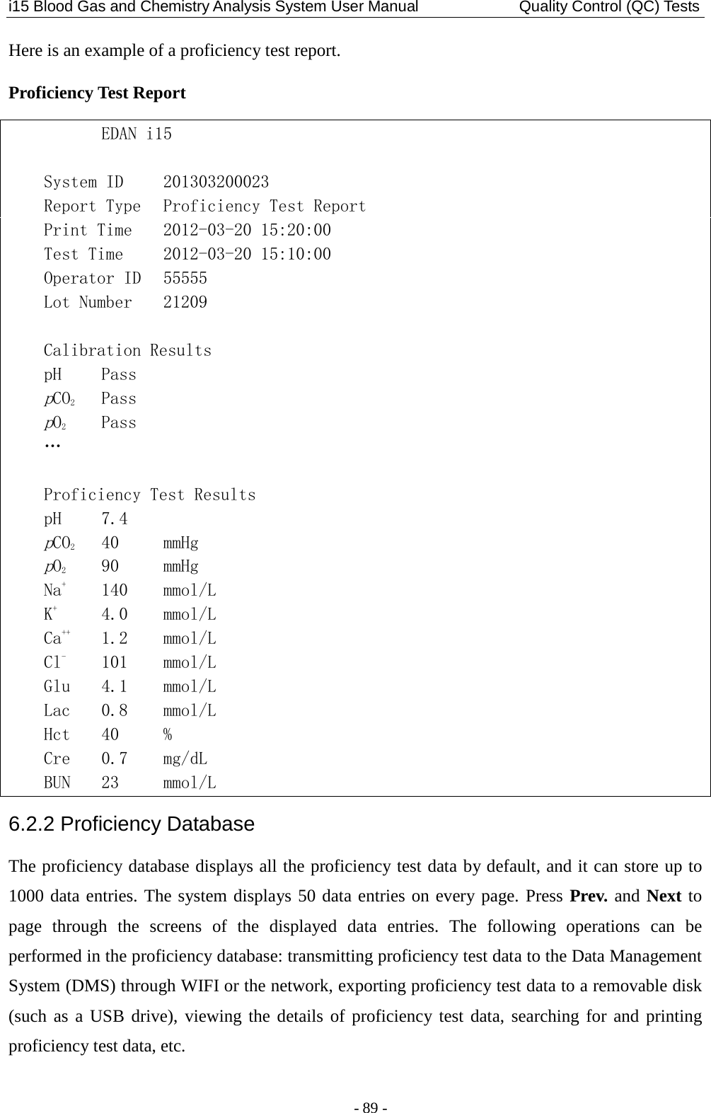
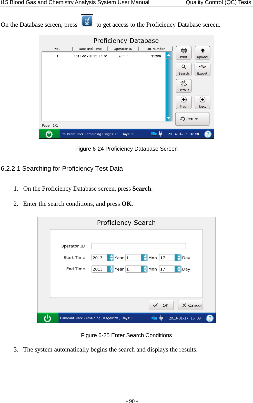
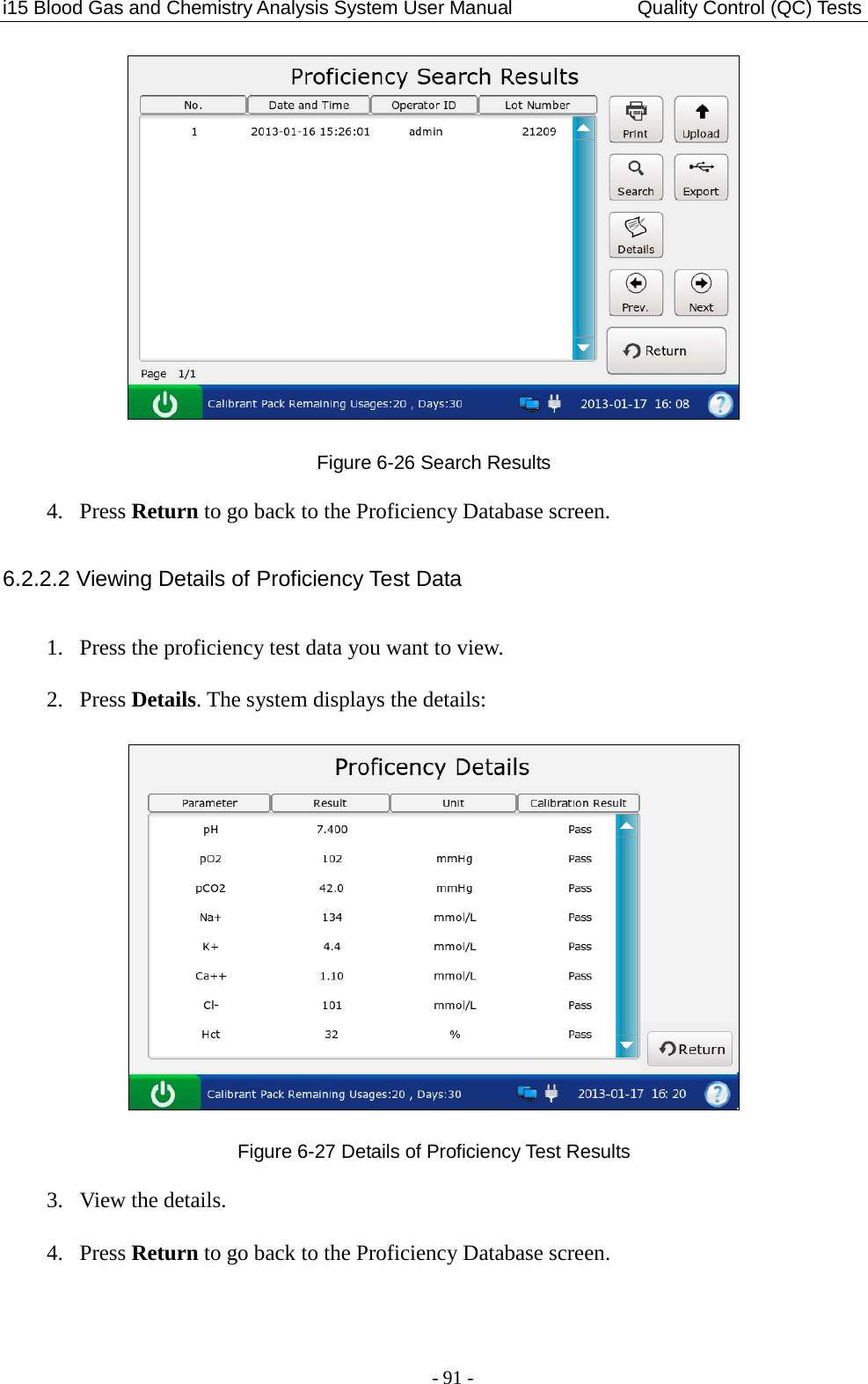
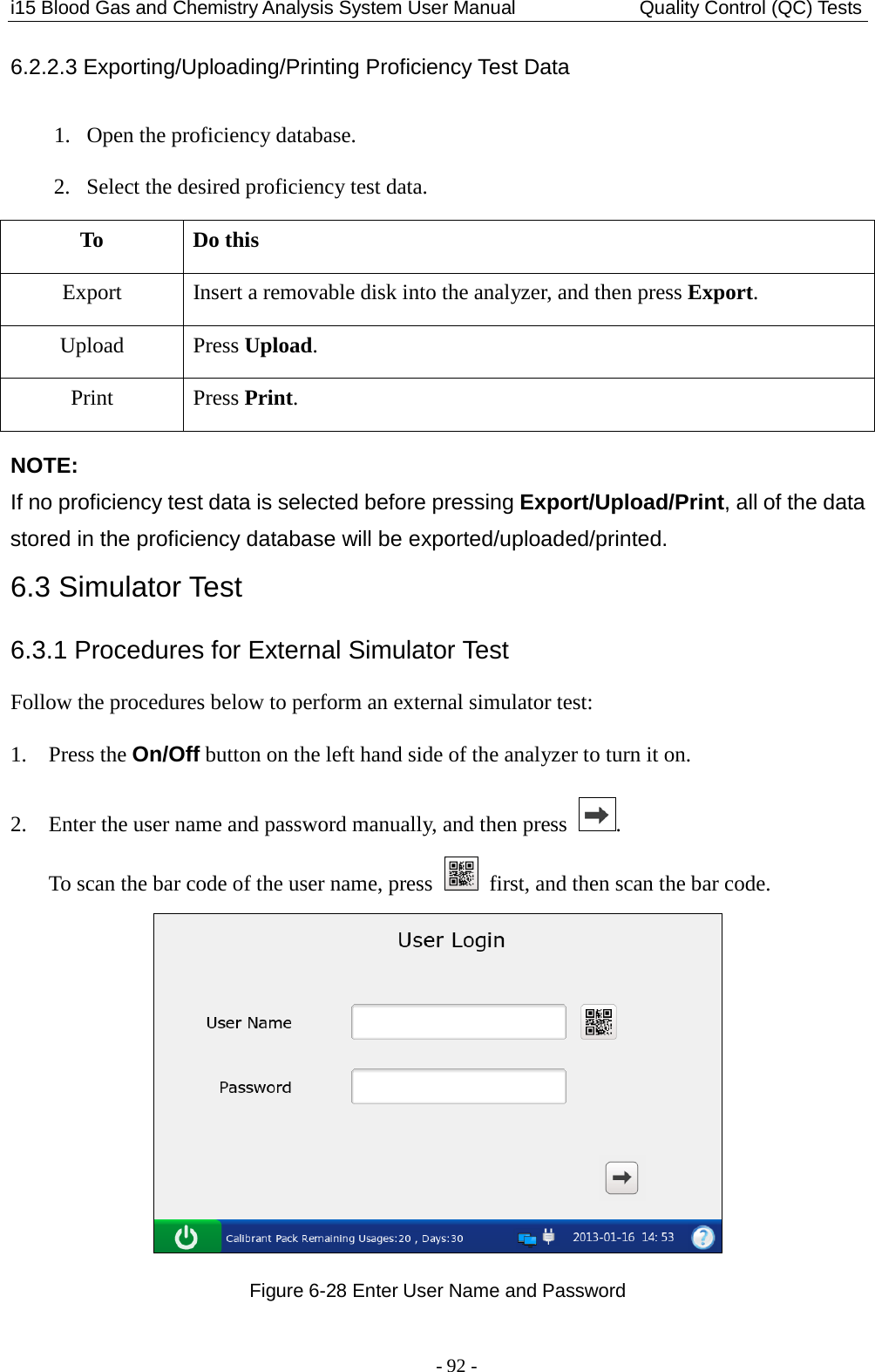
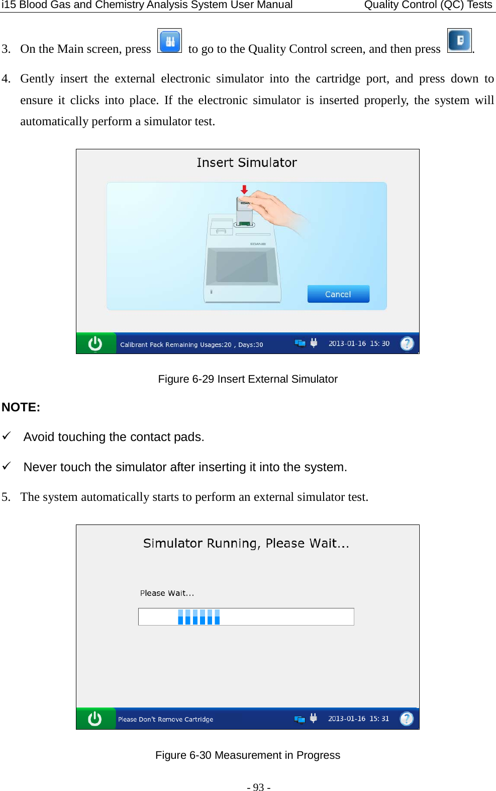
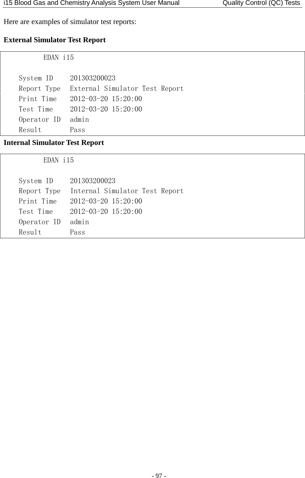
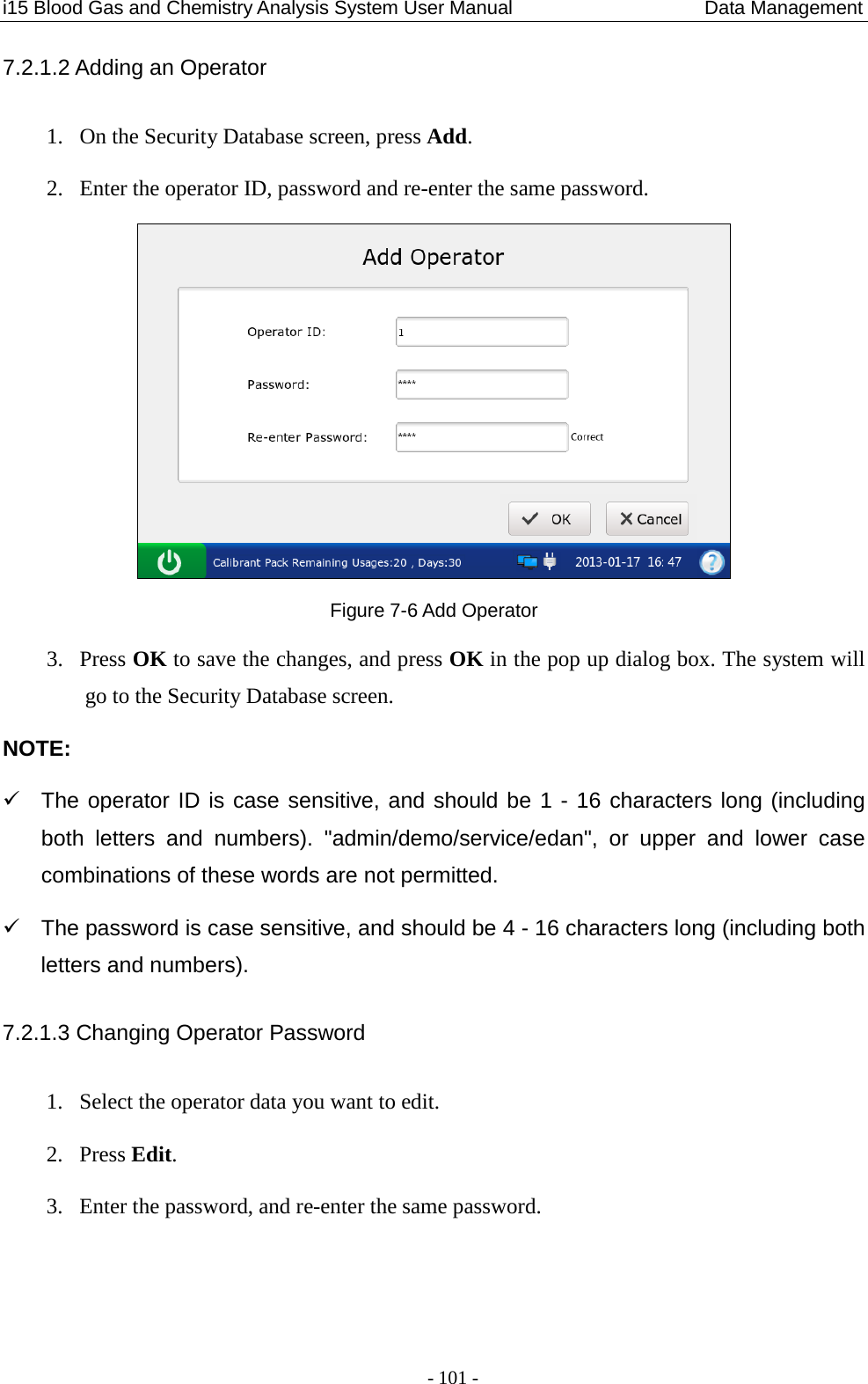
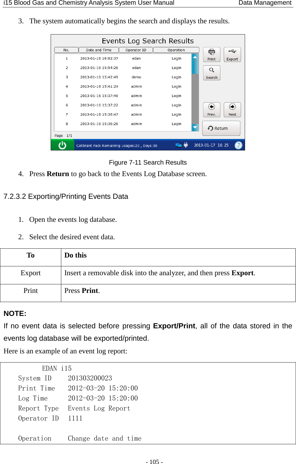
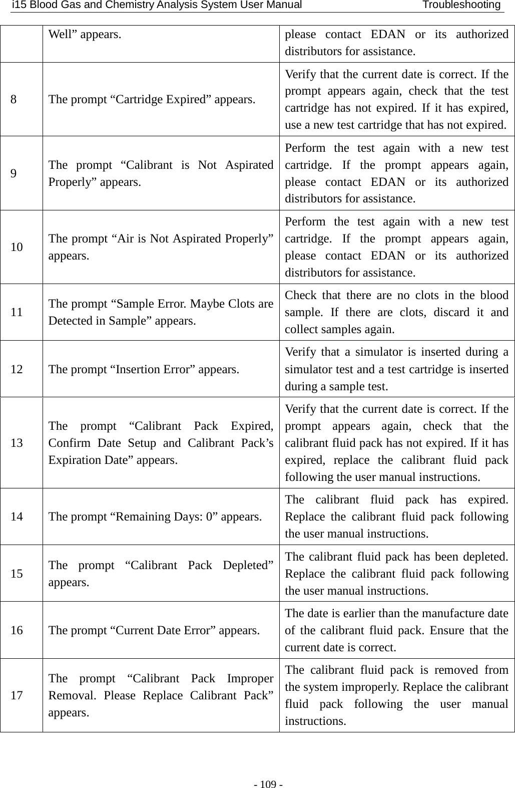
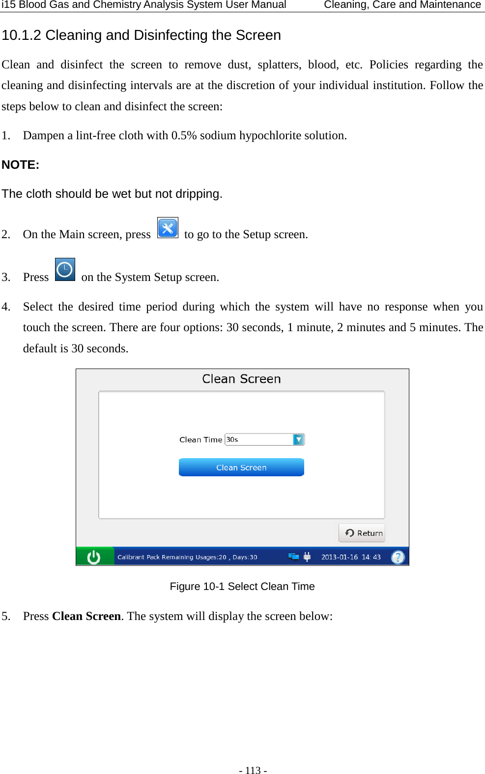
![i15 Blood Gas and Chemistry Analysis System User Manual Patient Analyzing - 64 - pCO2(T) 1 *** pO2(T) 1 > HCO3-act 1 < HCO3-std 1 BE(ecf) 1 Ca++(7.4) 1 … Reference Ranges pH [7.35 - 7.45] pCO2 [35.0 - 45.0] mmHg pO2 [80.0 - 100.0] mmHg Na+ [138.0 - 146.0] mmol/L K+ [3.50 - 4.90] mmol/L Ca++ [1.12 - 1.32] mmol/L Cl- [98 - 109] mmol/L Glu [3.9 - 5.8] mmol/L Lac [0.36 - 1.7] mmol/L Hct [35 – 51] % Cre [0.6 - 1.3] mg/dL BUN 5.2.2 Understanding Result Symbols The following table shows the symbols that may appear on the screen: Symbol Description > or < The result is above or below the measurement range. ↑ or ↓ The result is above or below the reference range. --- The measured parameter fails calibration. xxx The measured parameter fails quality control (QC) tests, and QC lockout function is enabled in Setup. *** The measured parameter fails quality control (QC) tests, and QC lockout function is disabled in Setup. The result for the calculated parameter is valid, but the measured parameter used to determine this calculated parameter fails quality control (QC) tests, and QC lockout function is disabled in Setup. ??? The result for the measured parameter is invalid. NOTE: Invalid test result for a calculated parameter will not be displayed on the screen. Valid test result for a calculated parameter will not be displayed on the screen, if the measured parameter used to determine the result fails quality control (QC) tests, and QC lockout function is enabled in Setup.](https://usermanual.wiki/EDAN-INSTRUMENTS/I15EDAN/User-Guide-2116883-Page-72.png)
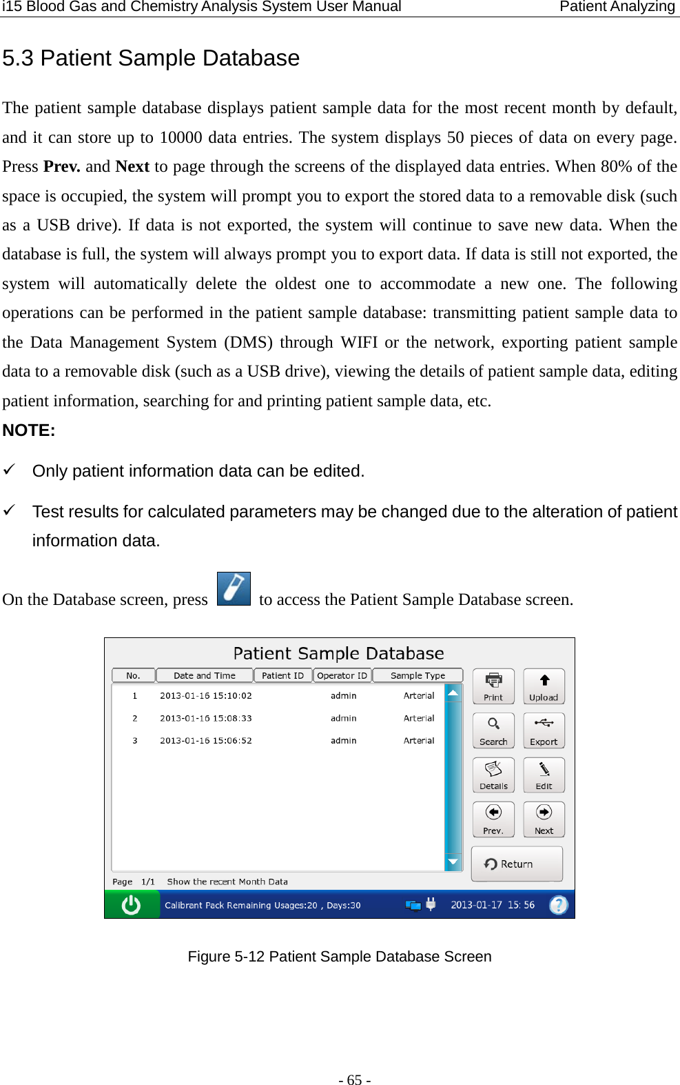
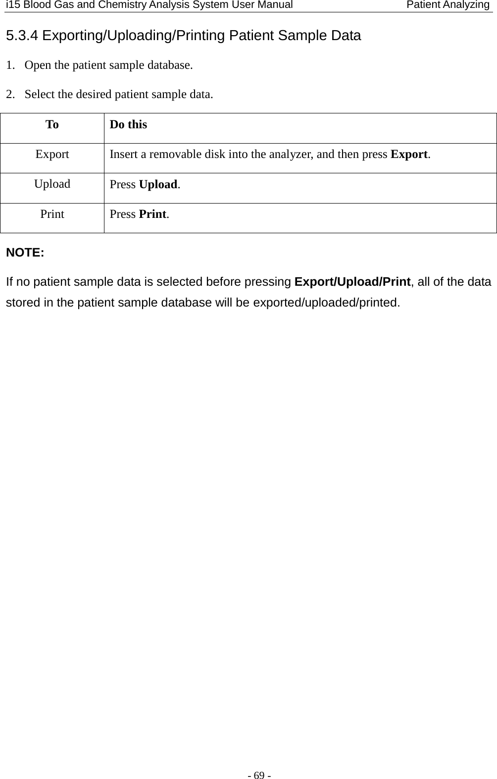
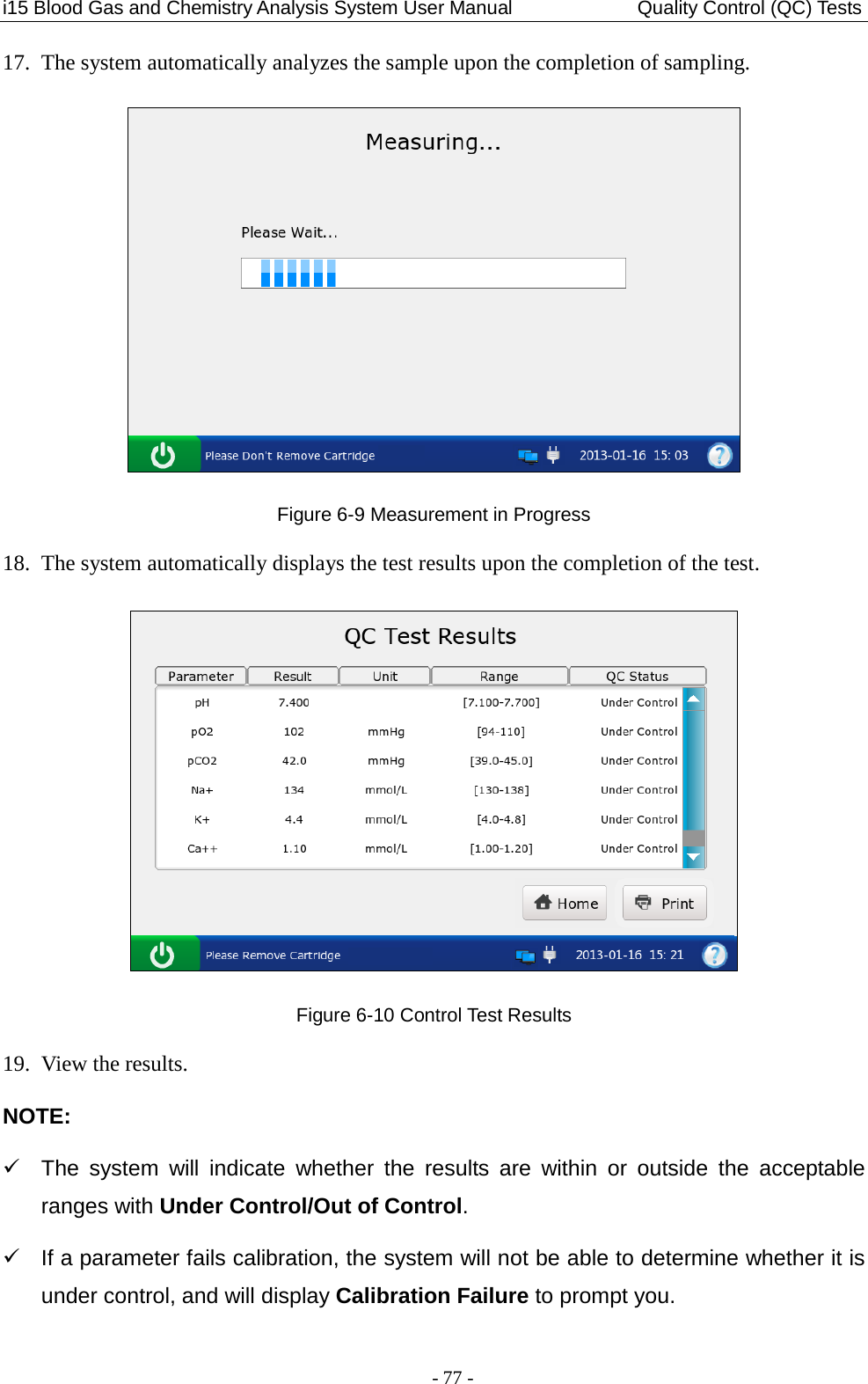
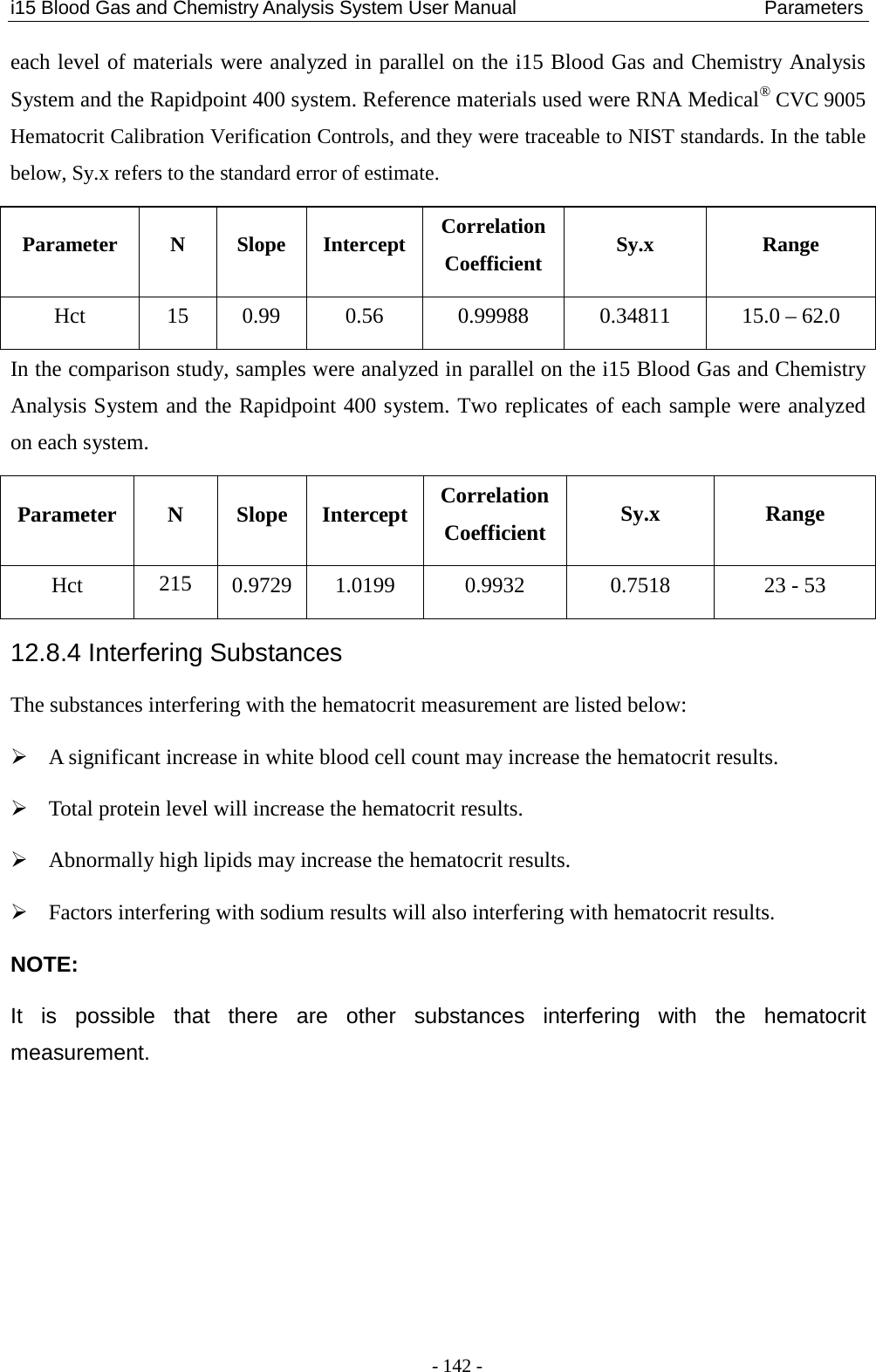
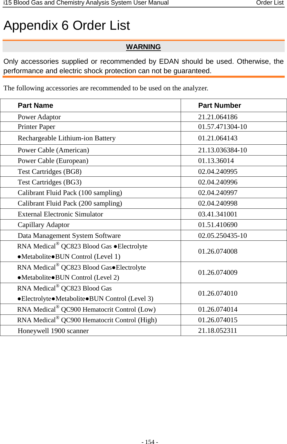
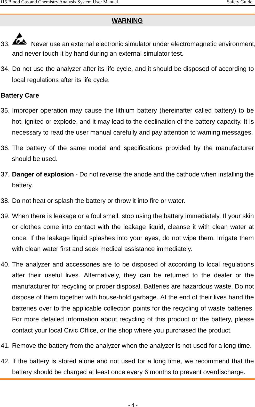
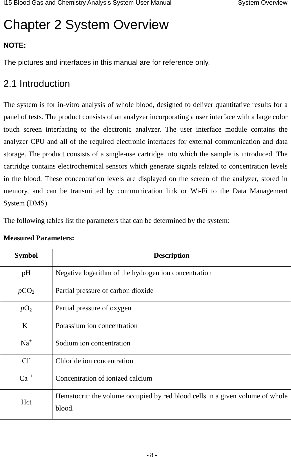
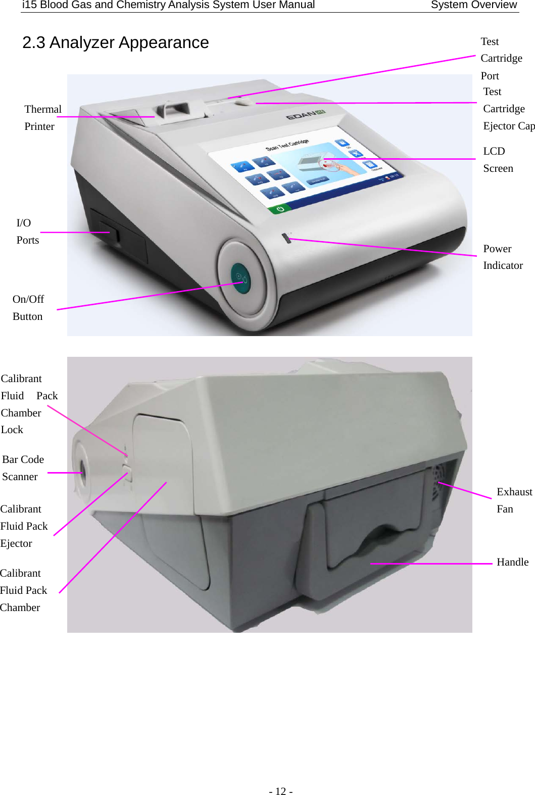
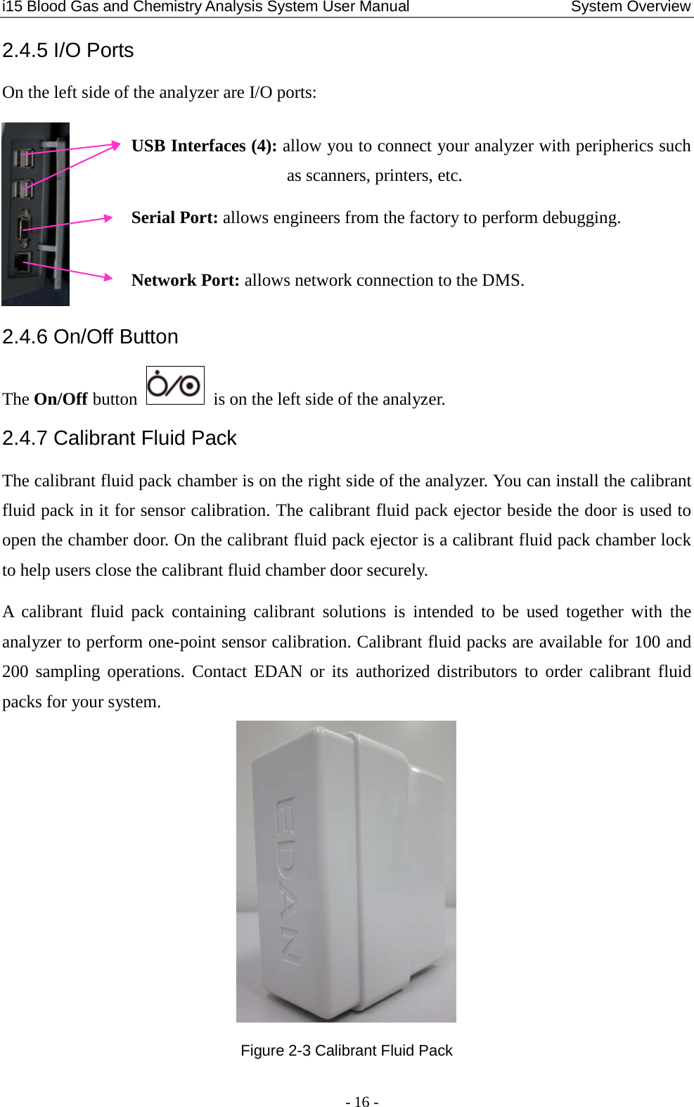
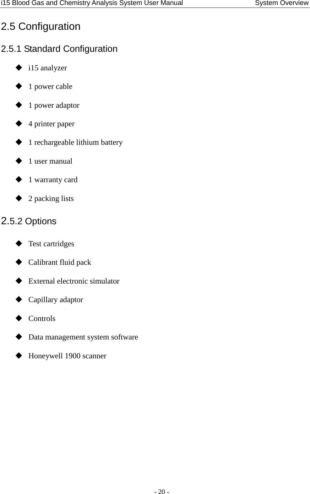
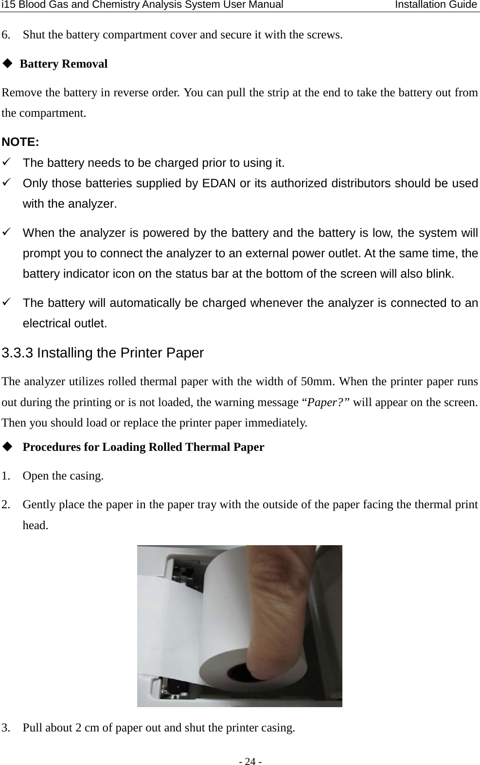
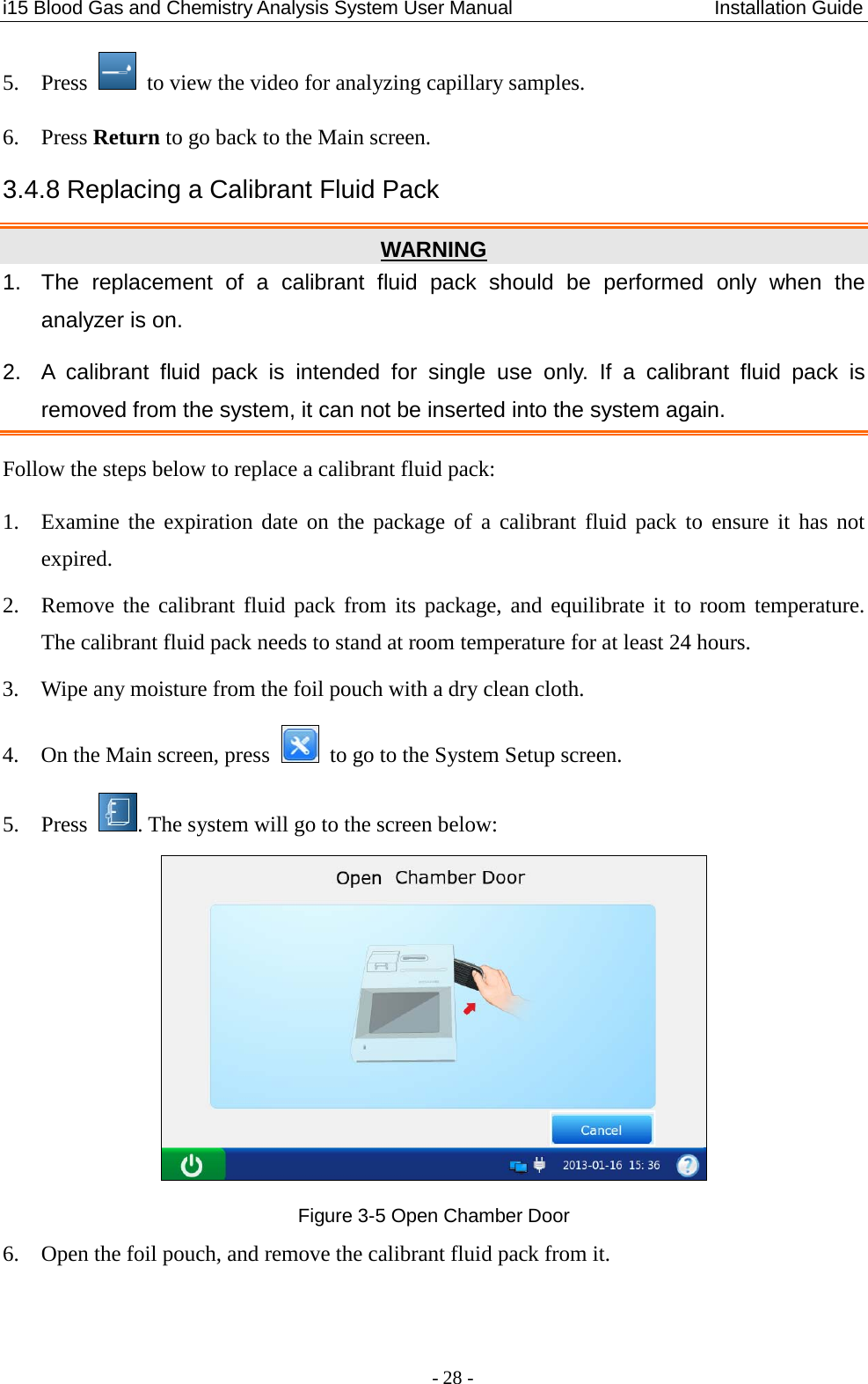
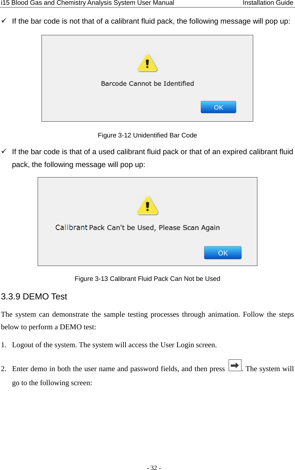
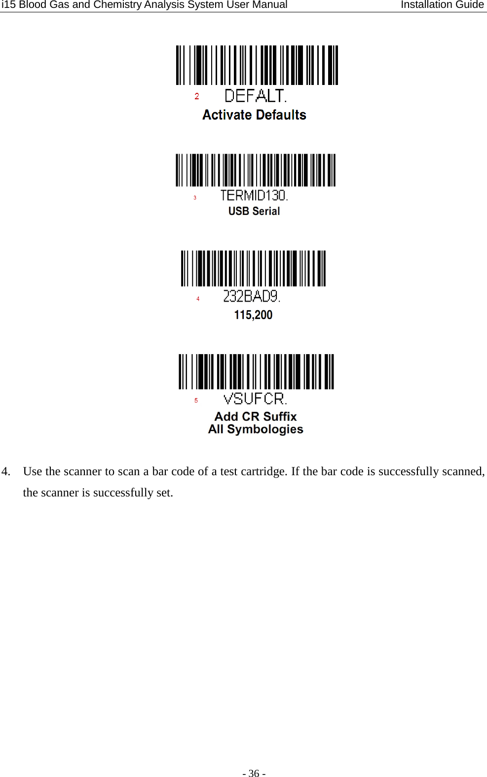
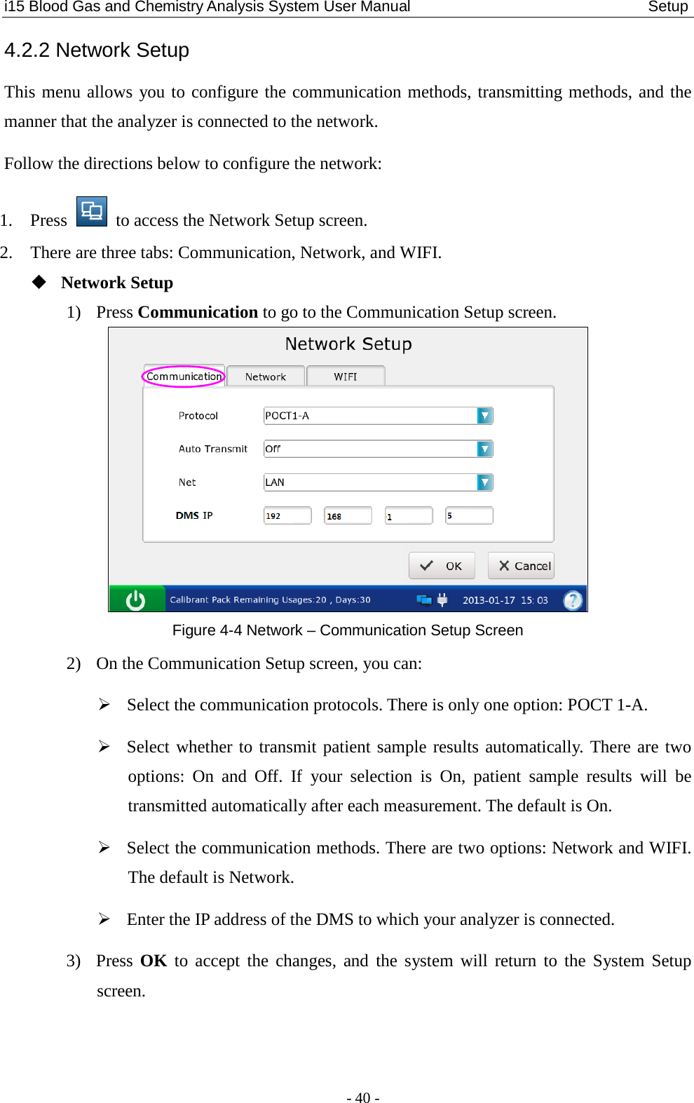
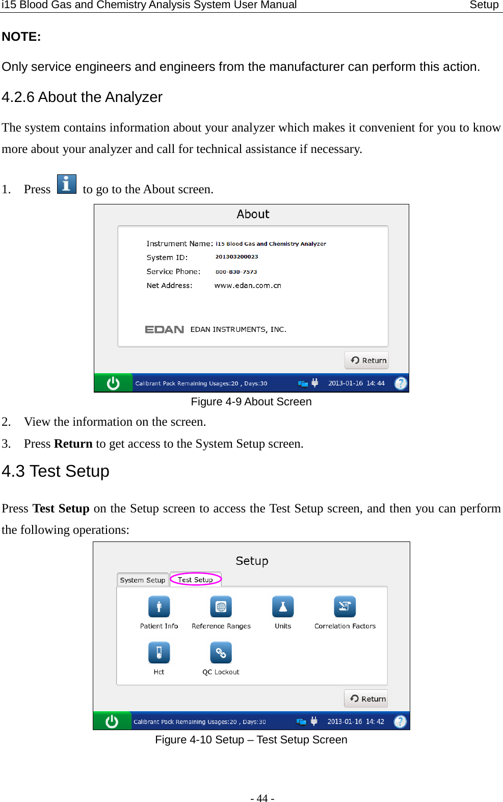
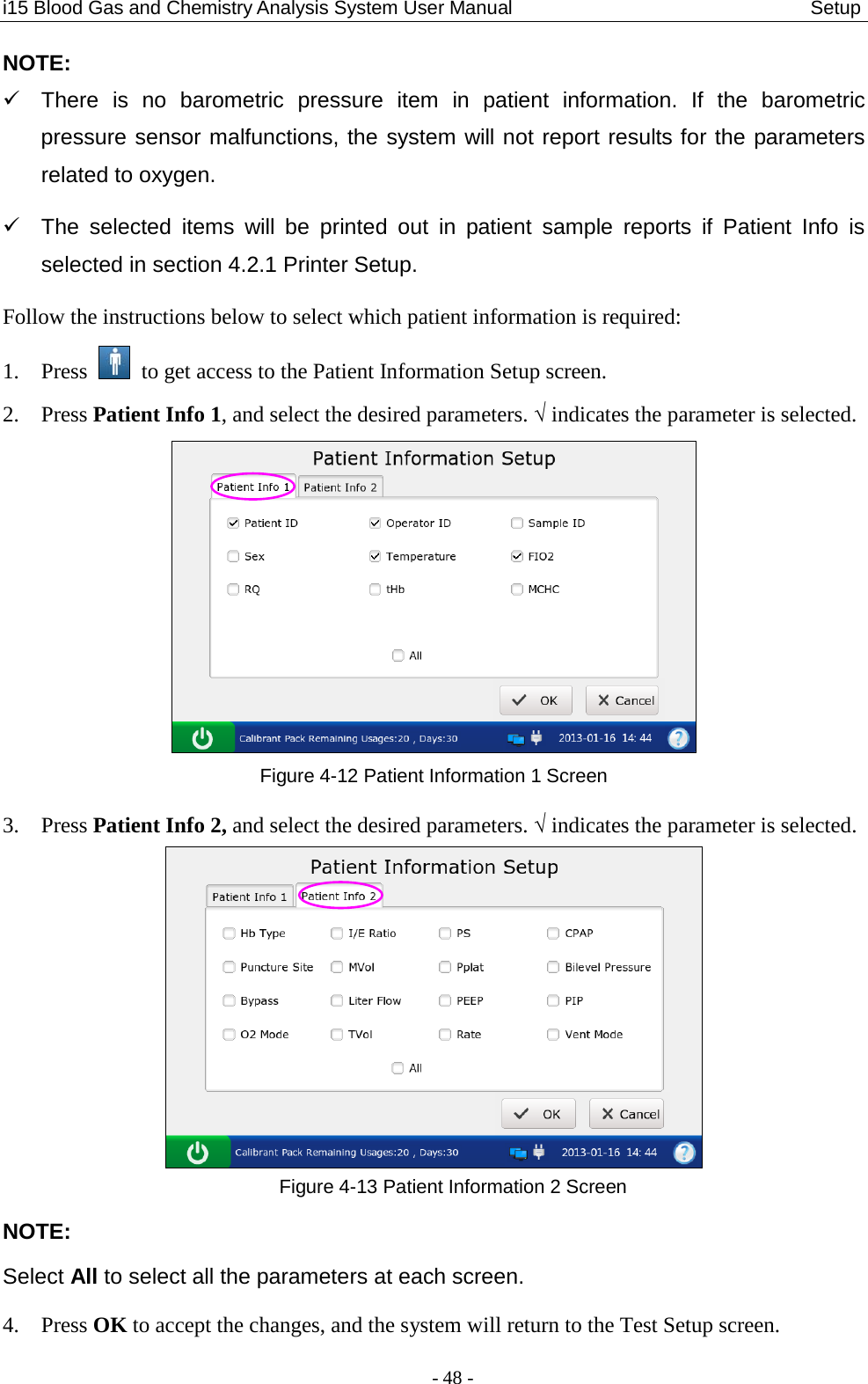
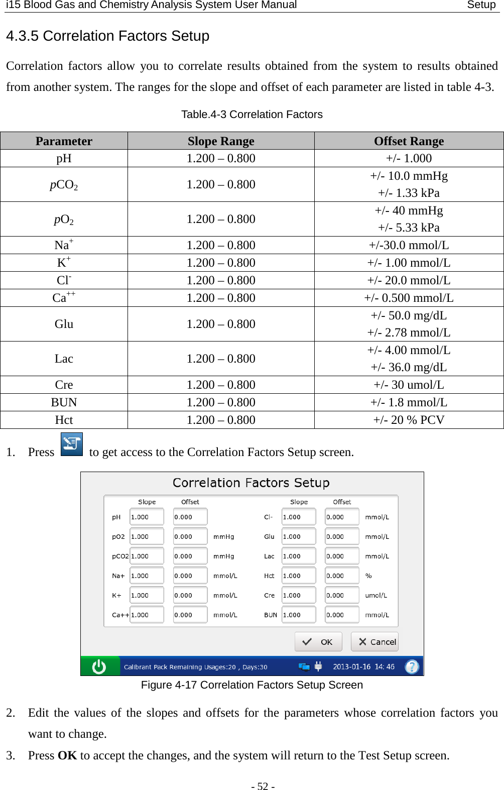
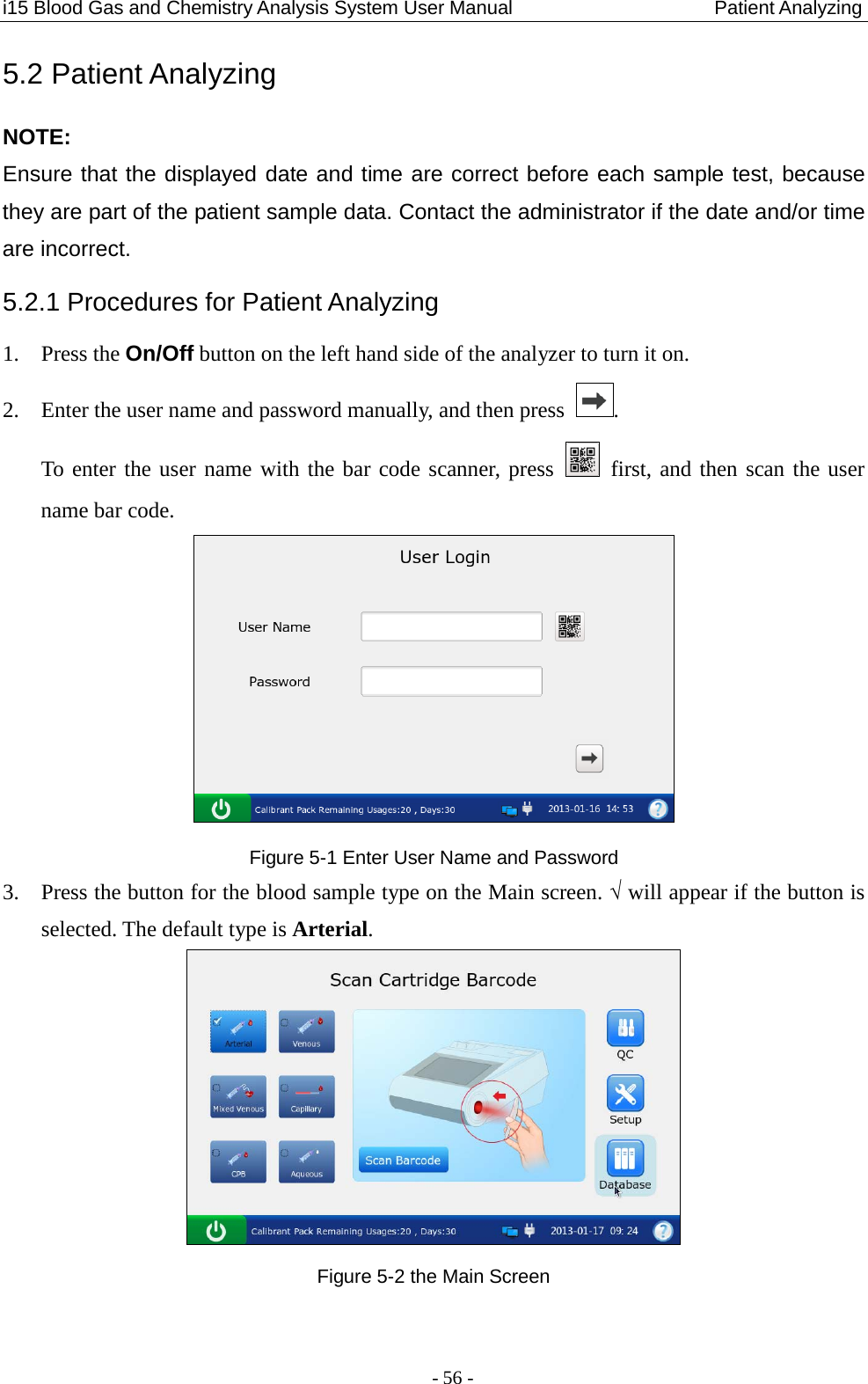
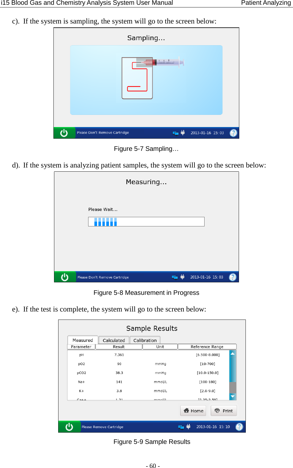
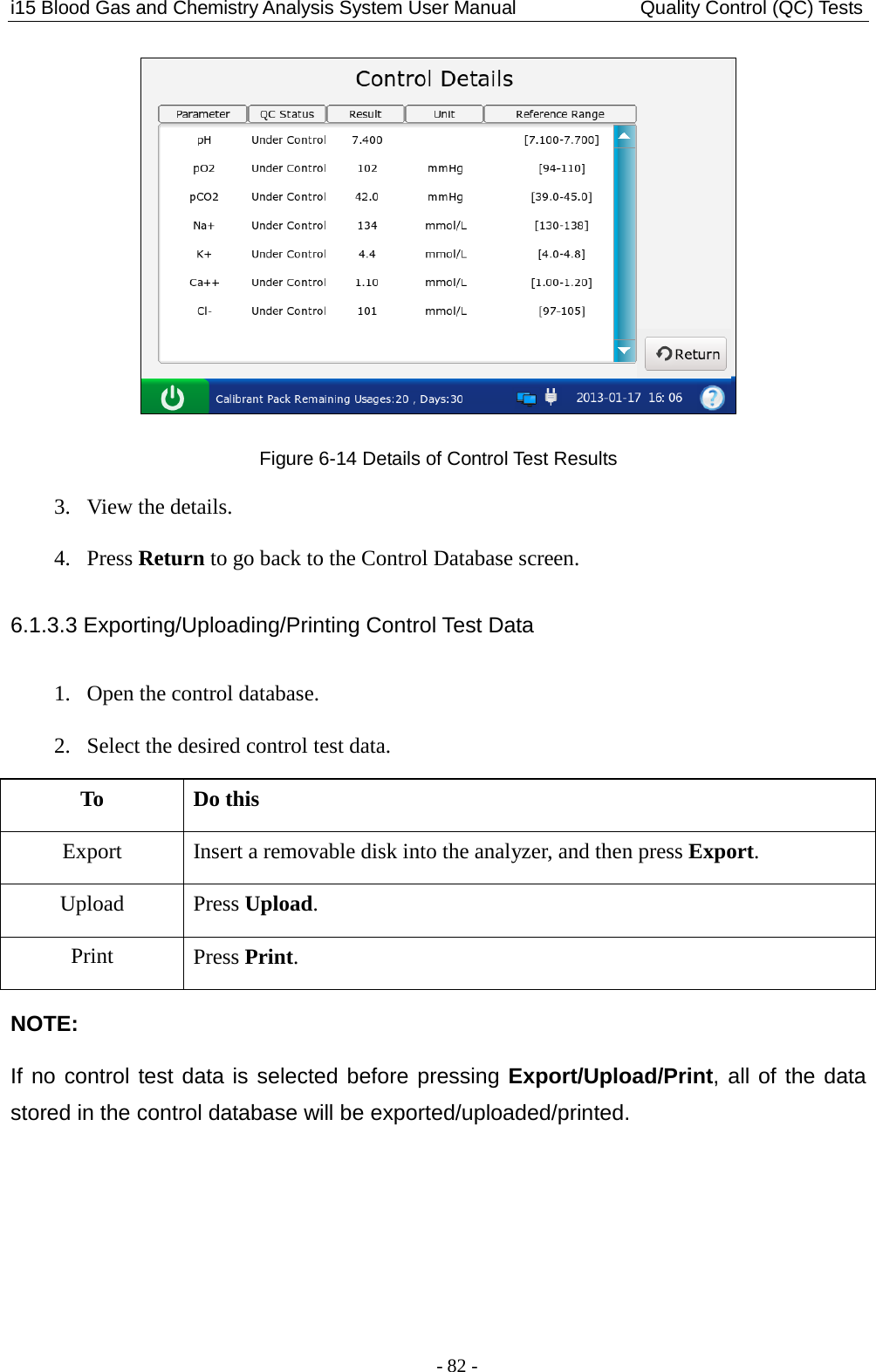
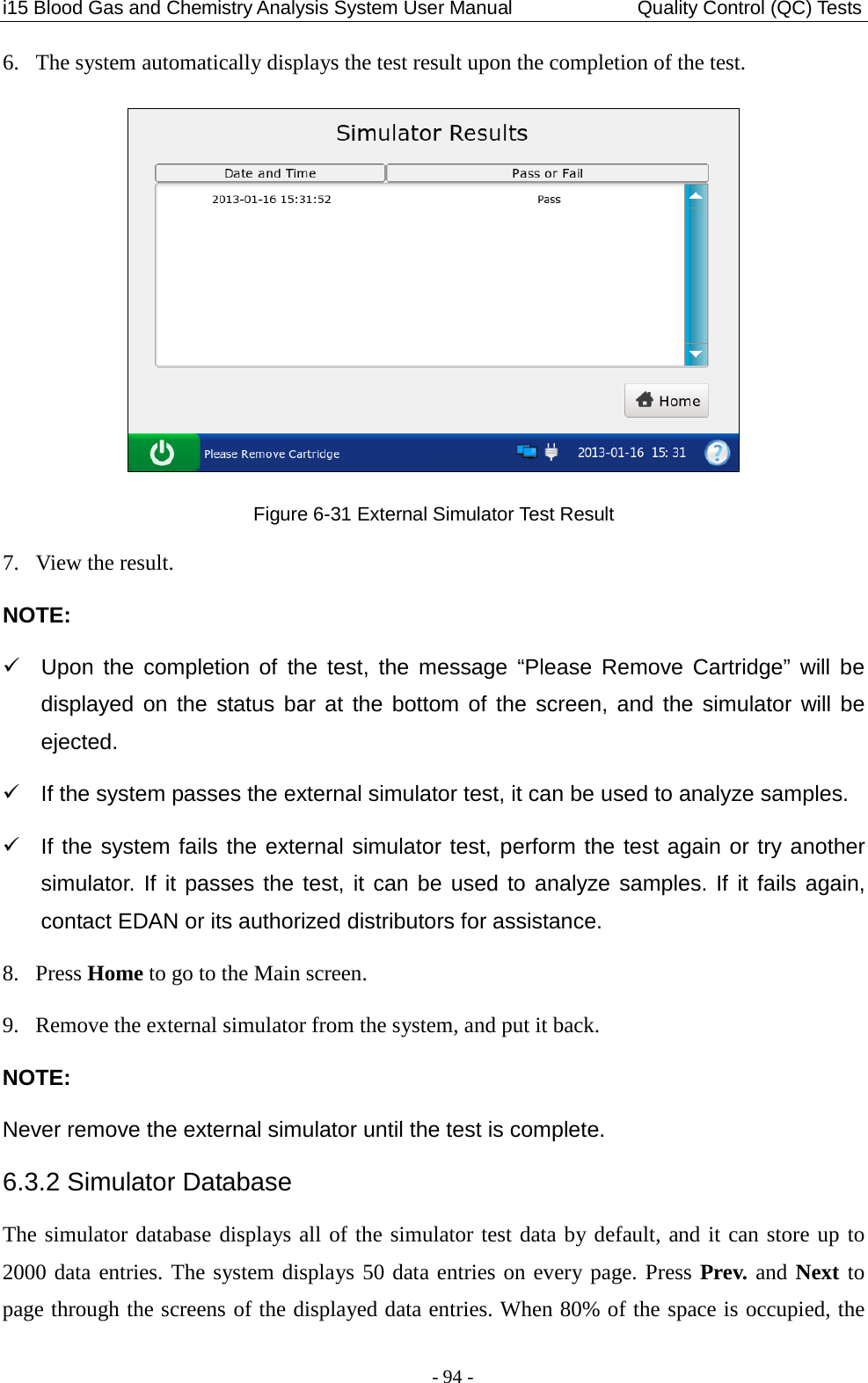
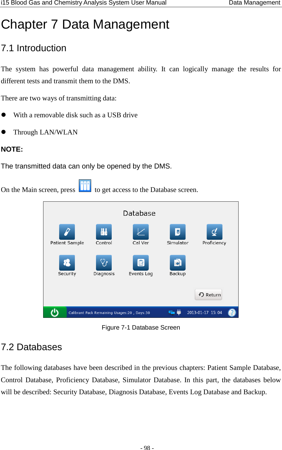
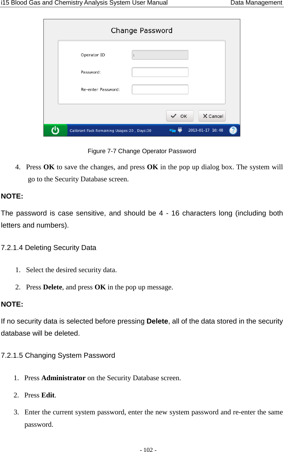
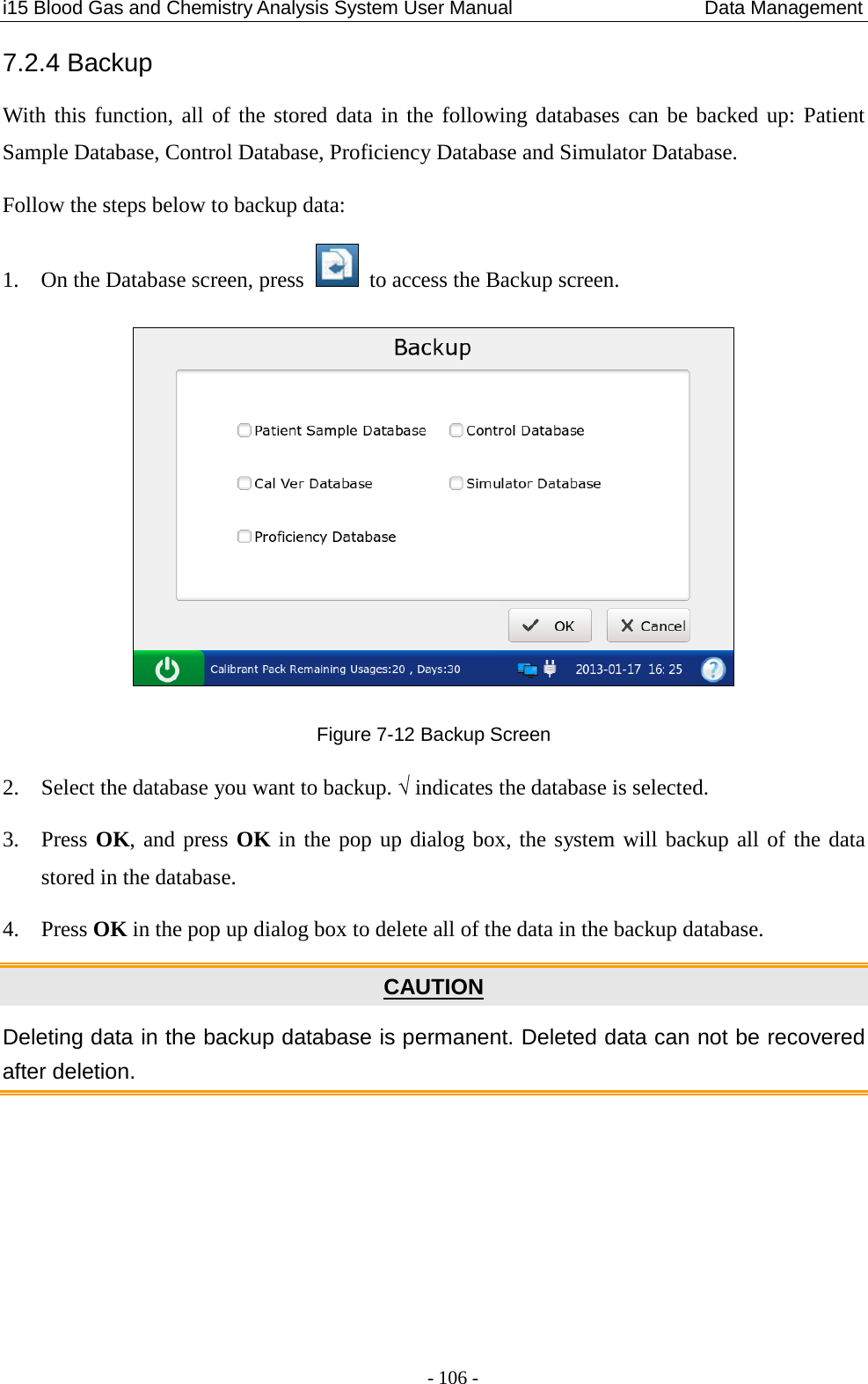
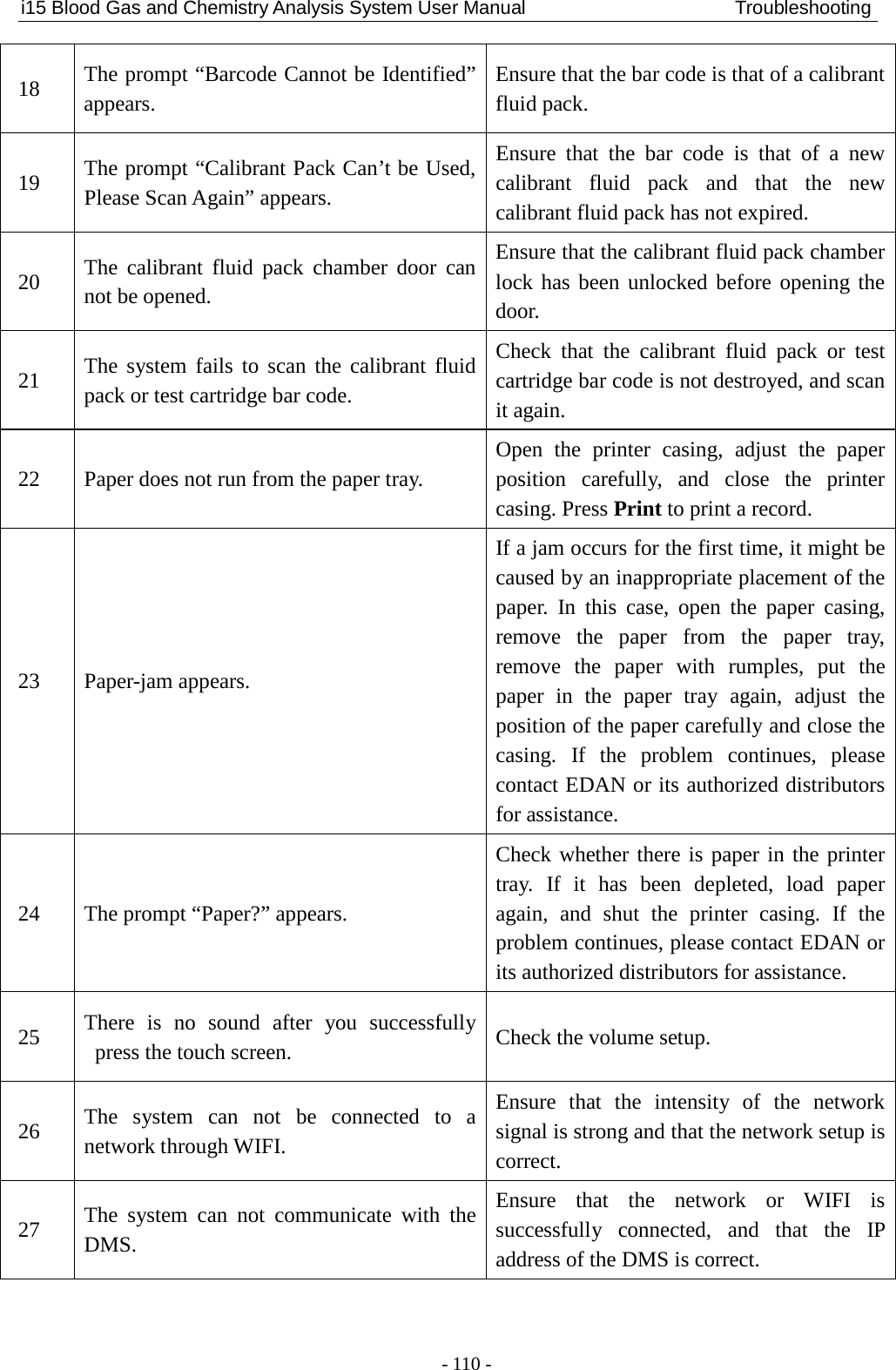
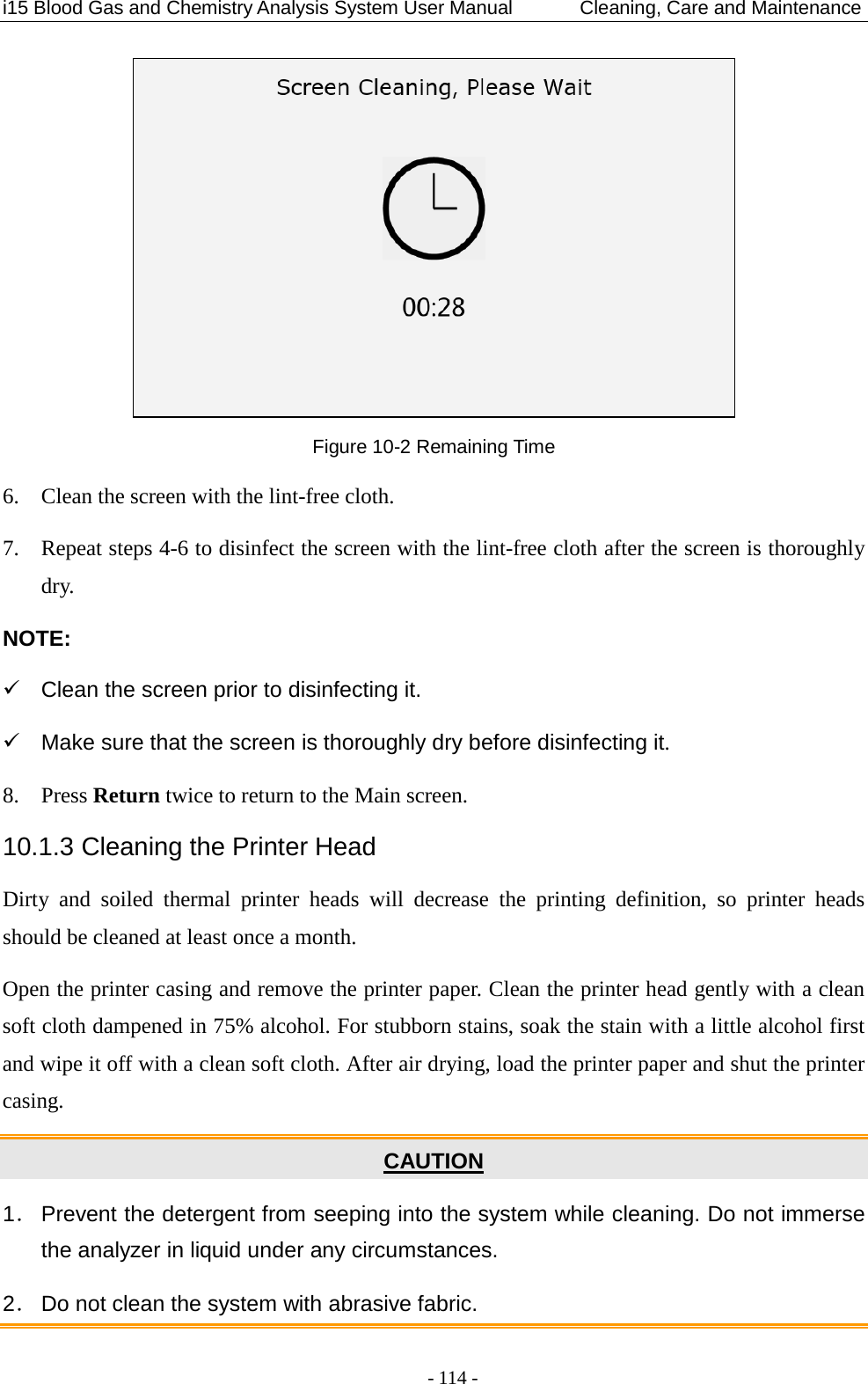
![i15 Blood Gas and Chemistry Analysis System User Manual Quality Control (QC) Tests - 79 - Control Test Results pH 7.5 pCO2 --- mmHg pO2 70 mmHg Na+ K+ Ca++ Cl- Glu Lac Hct Cre BUN pH Under Control pCO2 Calibration Failure pO2 Under Control Na+ Under Control K+ Under Control Ca++ Under Control Cl- Under Control Glu Under Control Lac Under Control Hct Under Control Cre Under Control BUN Under Control Control Ranges pH [7.35 - 7.45] pCO2 [35.0 - 45.0] mmHg pO2 [80.0 - 100.0] mmHg Na+ [138.0 - 146.0] mmol/L K+ [3.50 - 4.90] mmol/L Ca++ [1.12 - 1.32] mmol/L Cl- [98 – 109] mmol/L Glu [3.9 - 5.8] mmol/L Lac [0.36 - 1.7] mmol/L Hct [35 – 51] % Cre [0.6 - 1.3] mg/dL BUN](https://usermanual.wiki/EDAN-INSTRUMENTS/I15EDAN/User-Guide-2116883-Page-87.png)
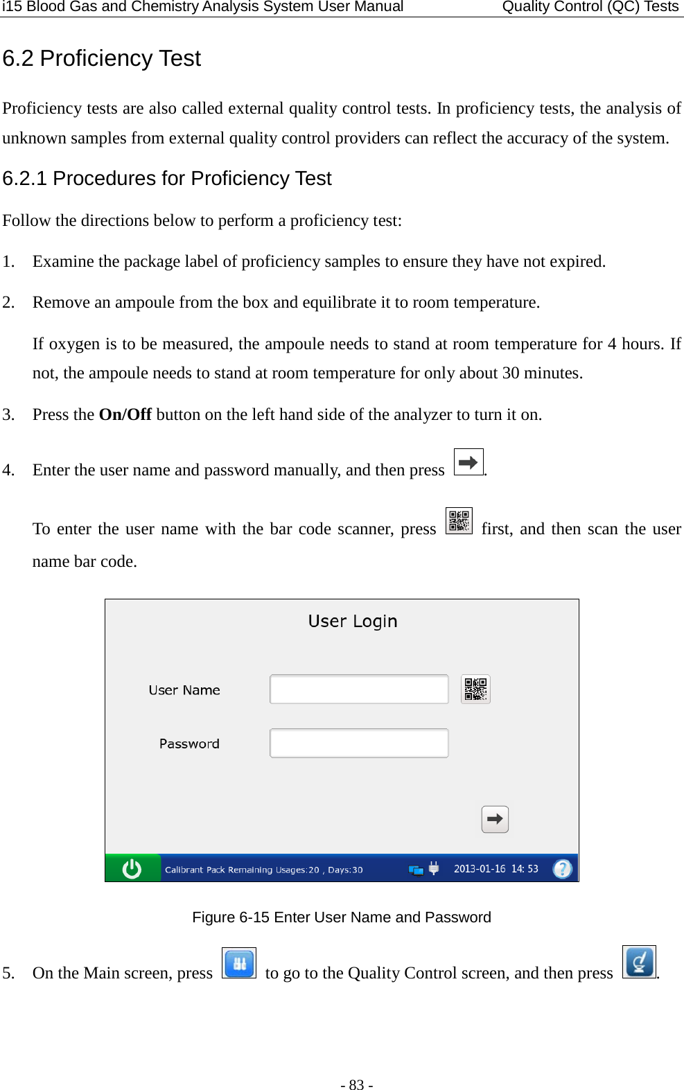
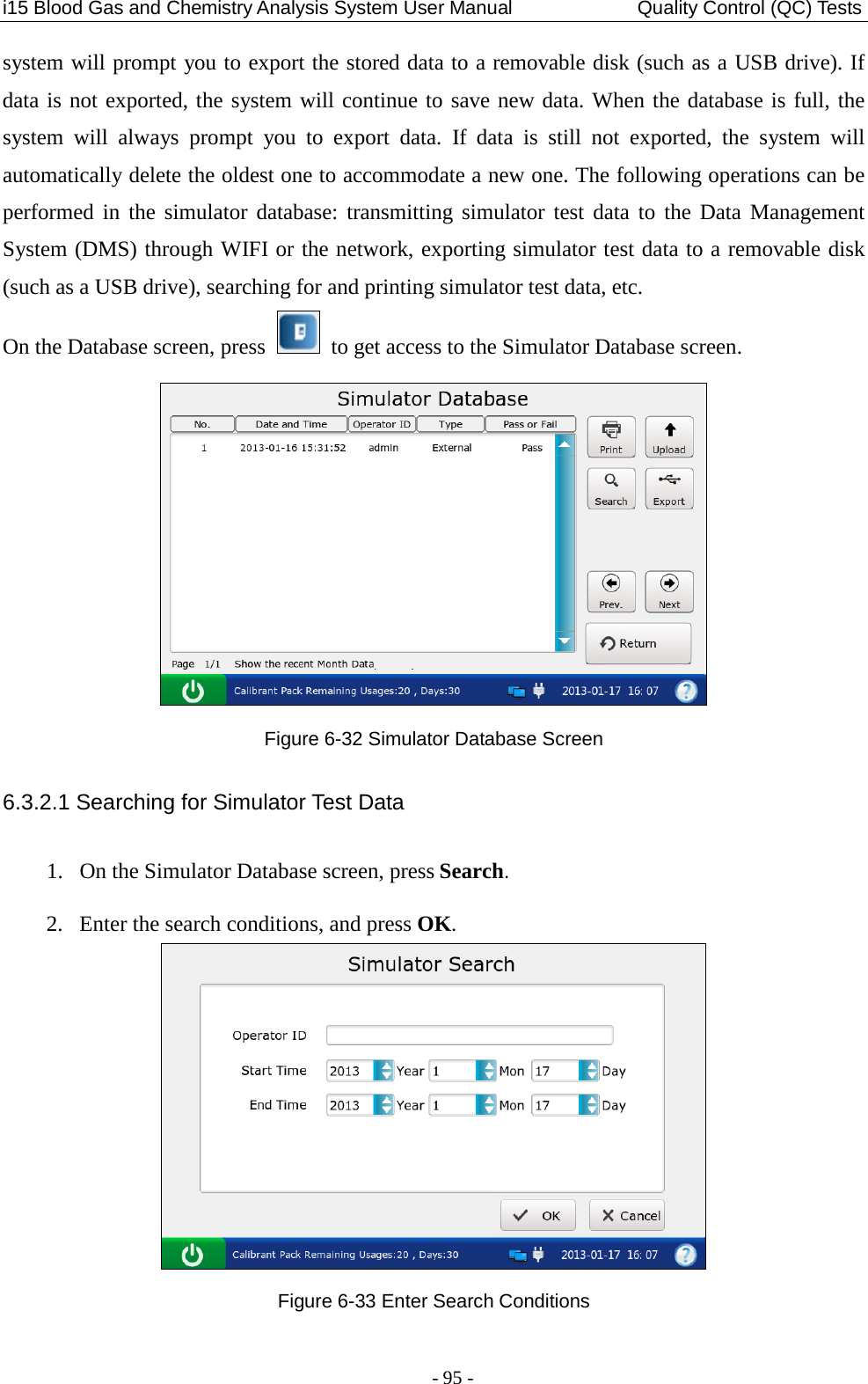
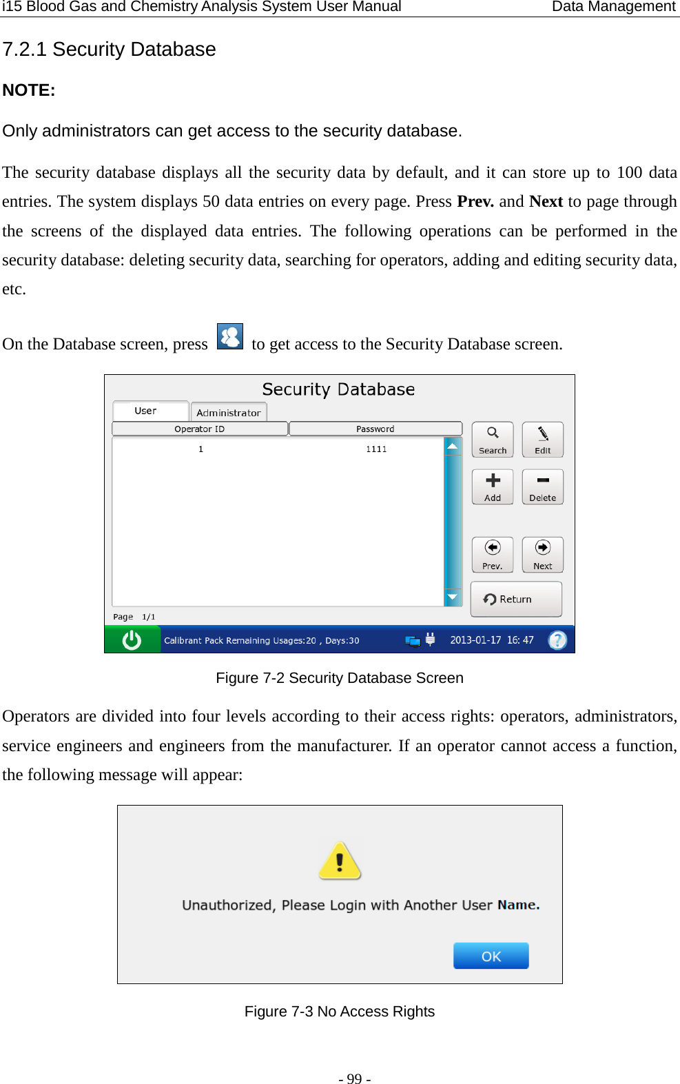
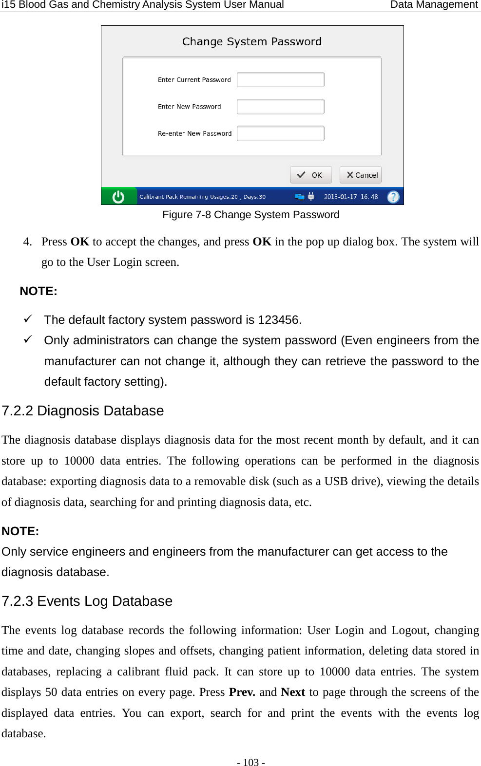
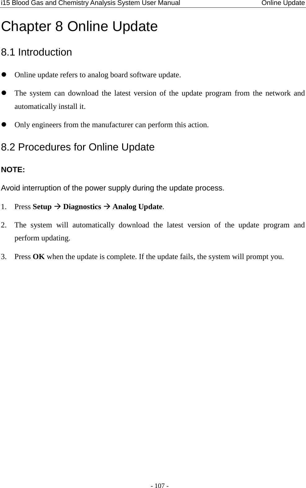
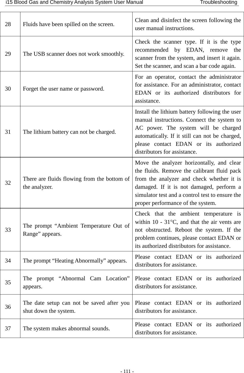
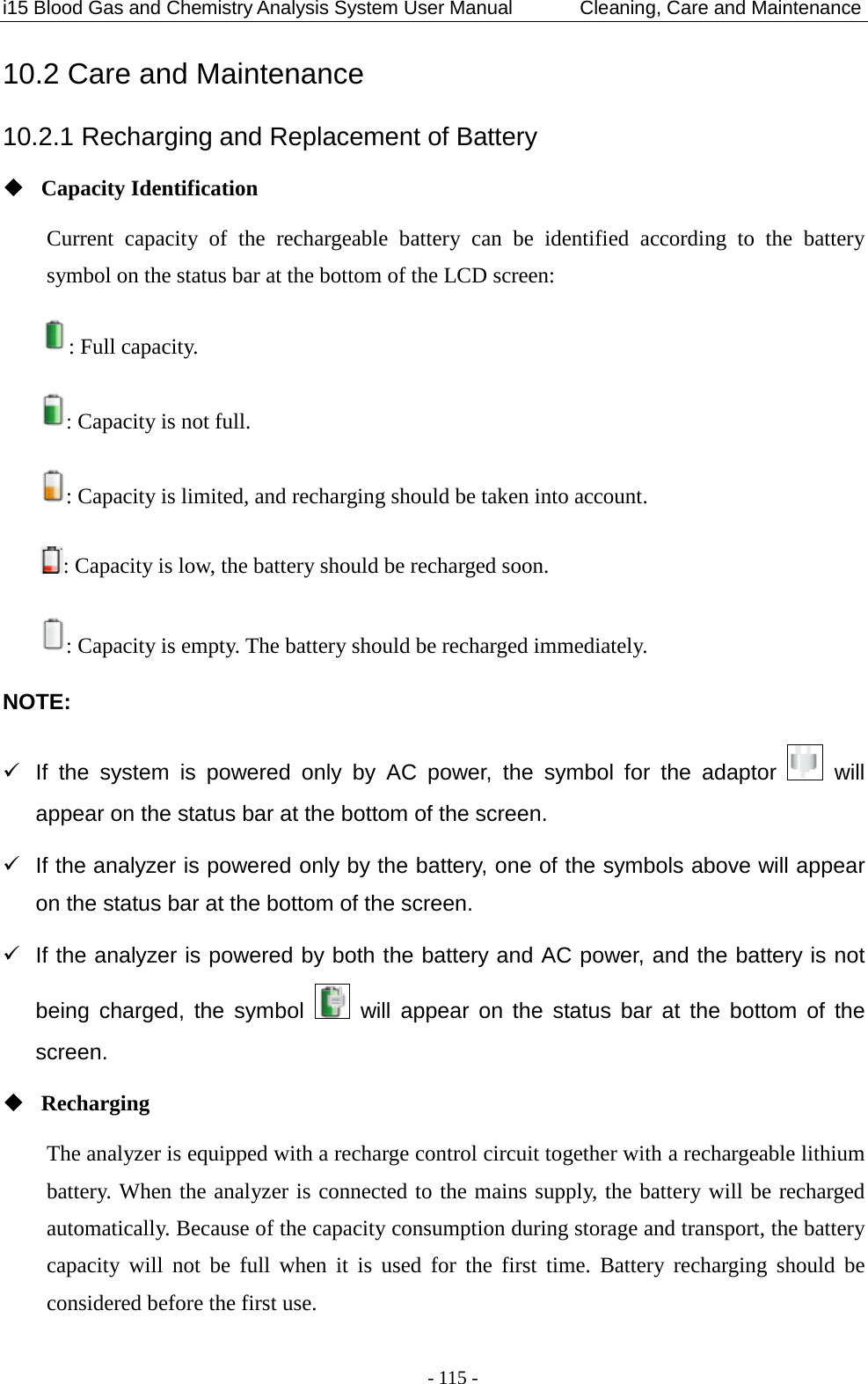
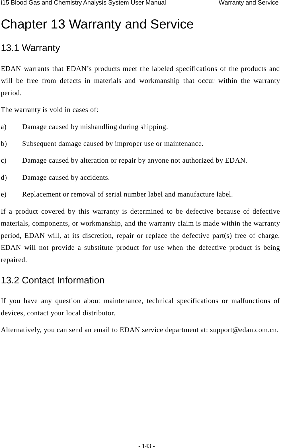
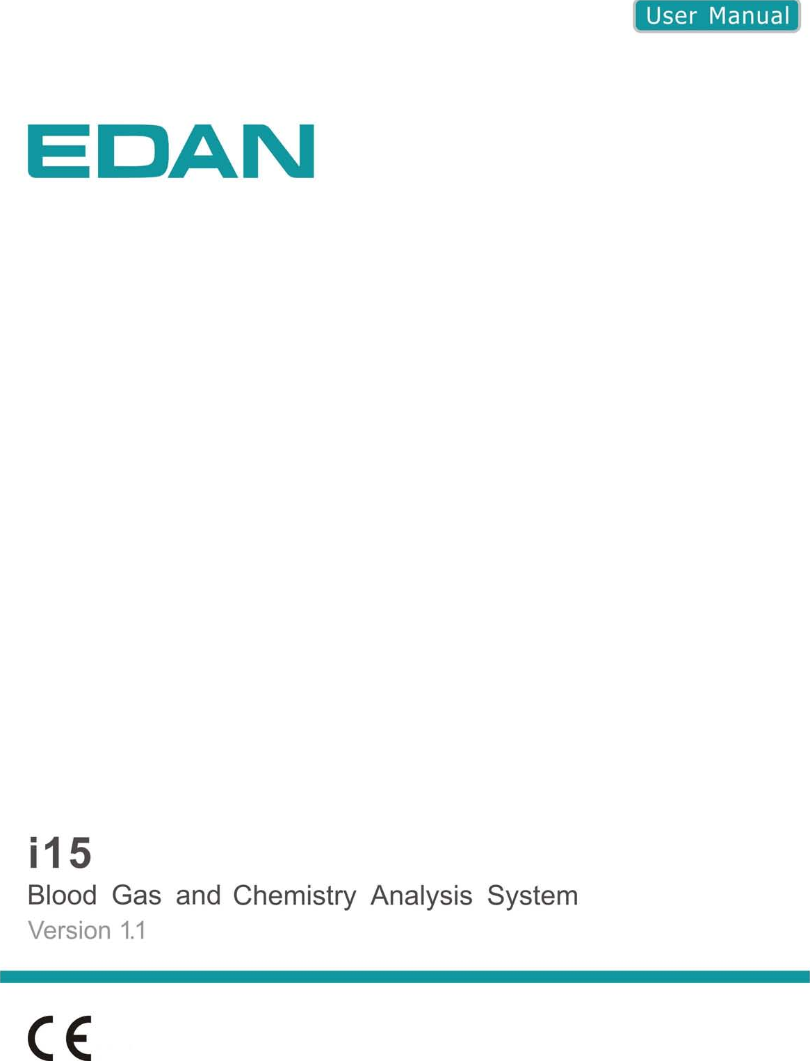
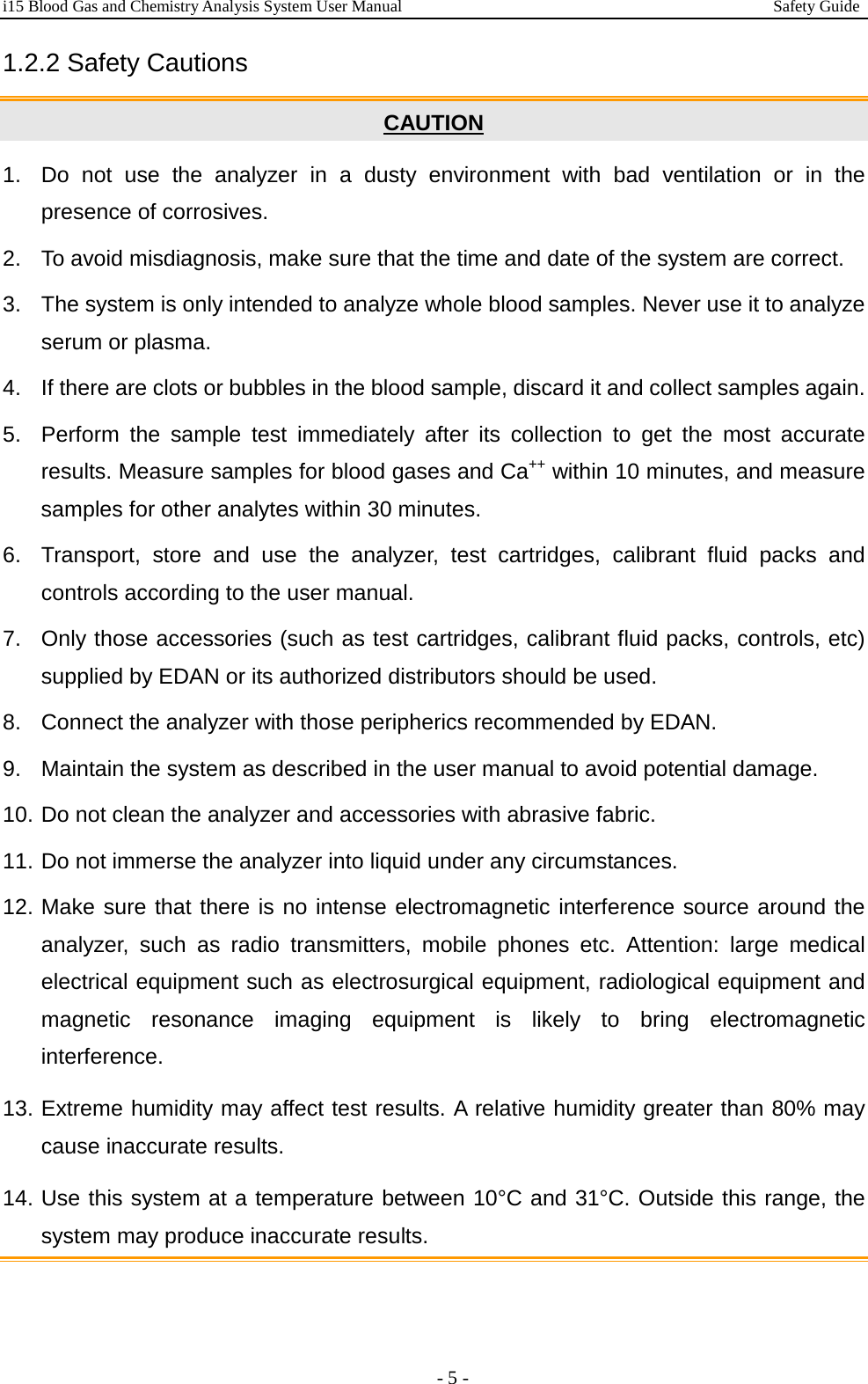
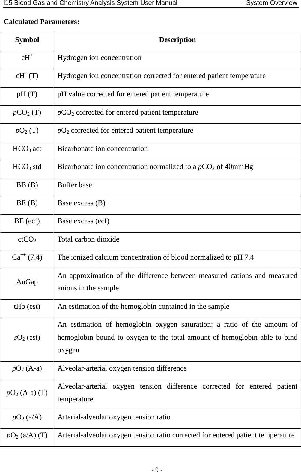
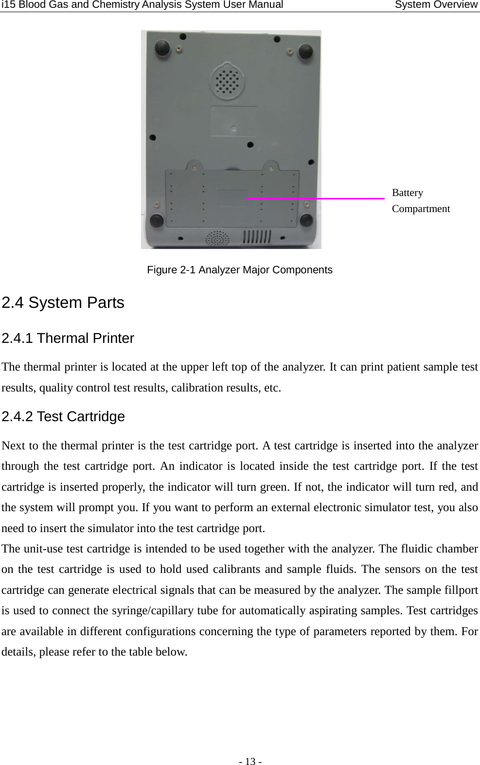
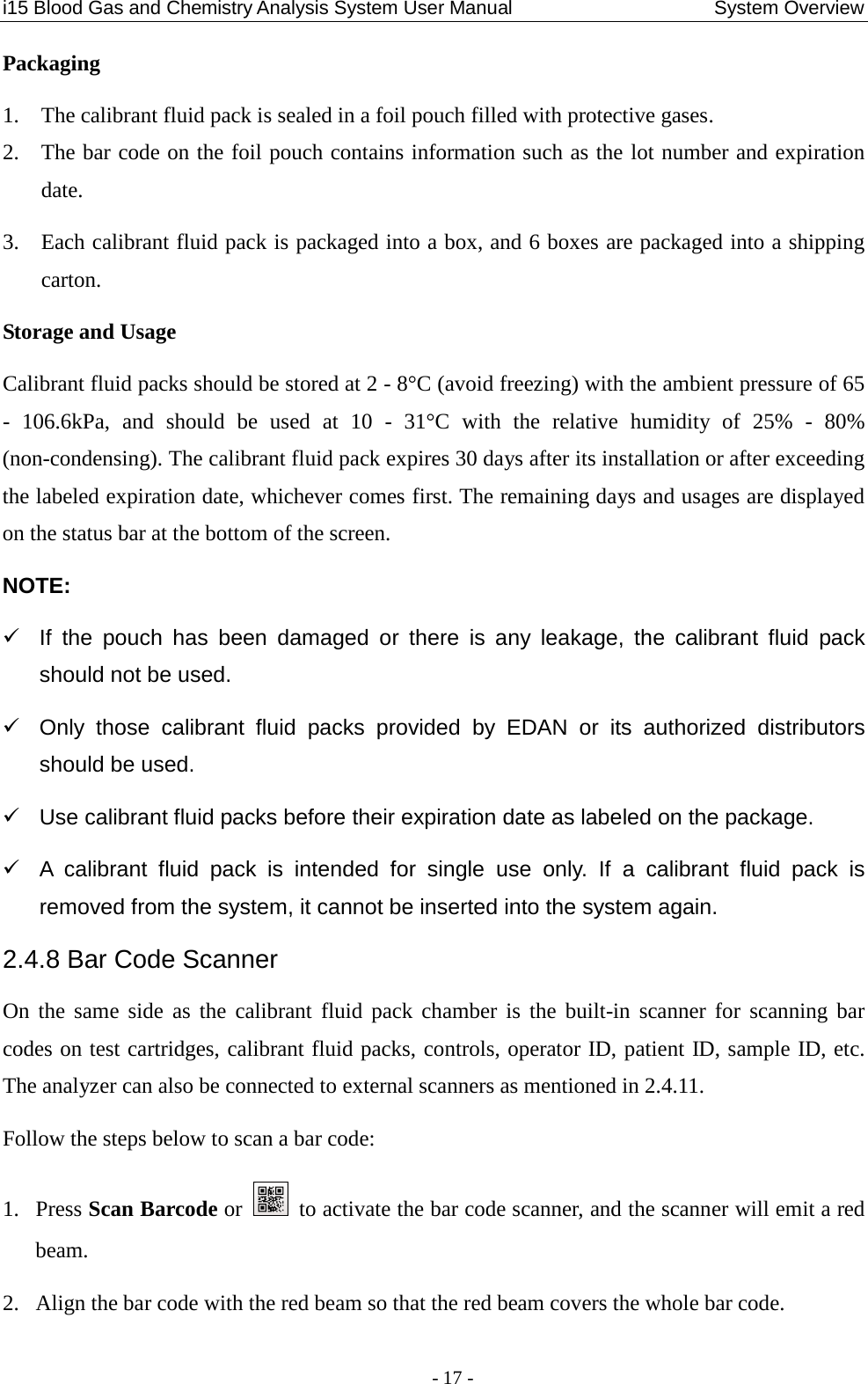
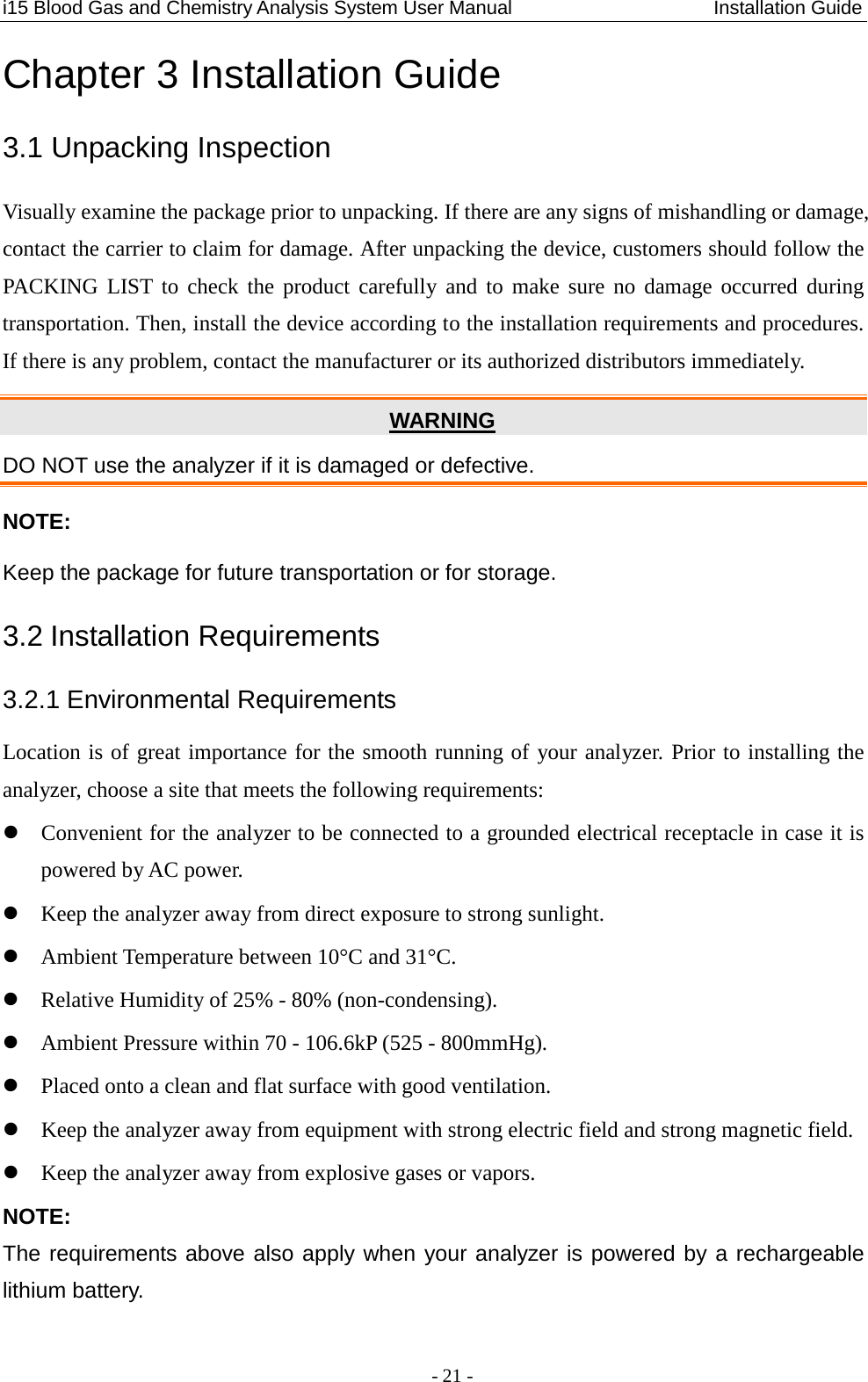
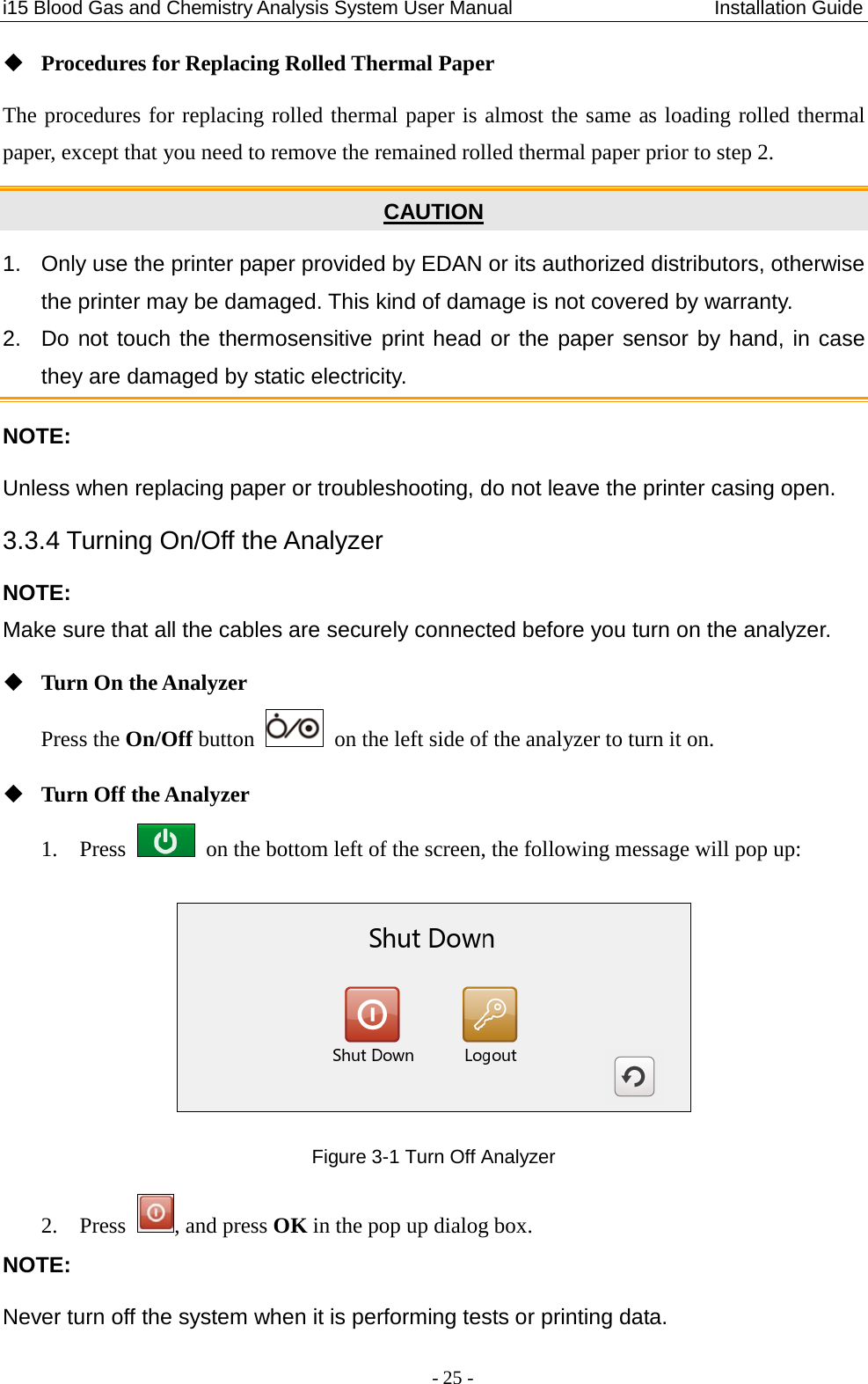
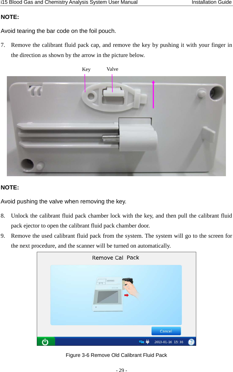
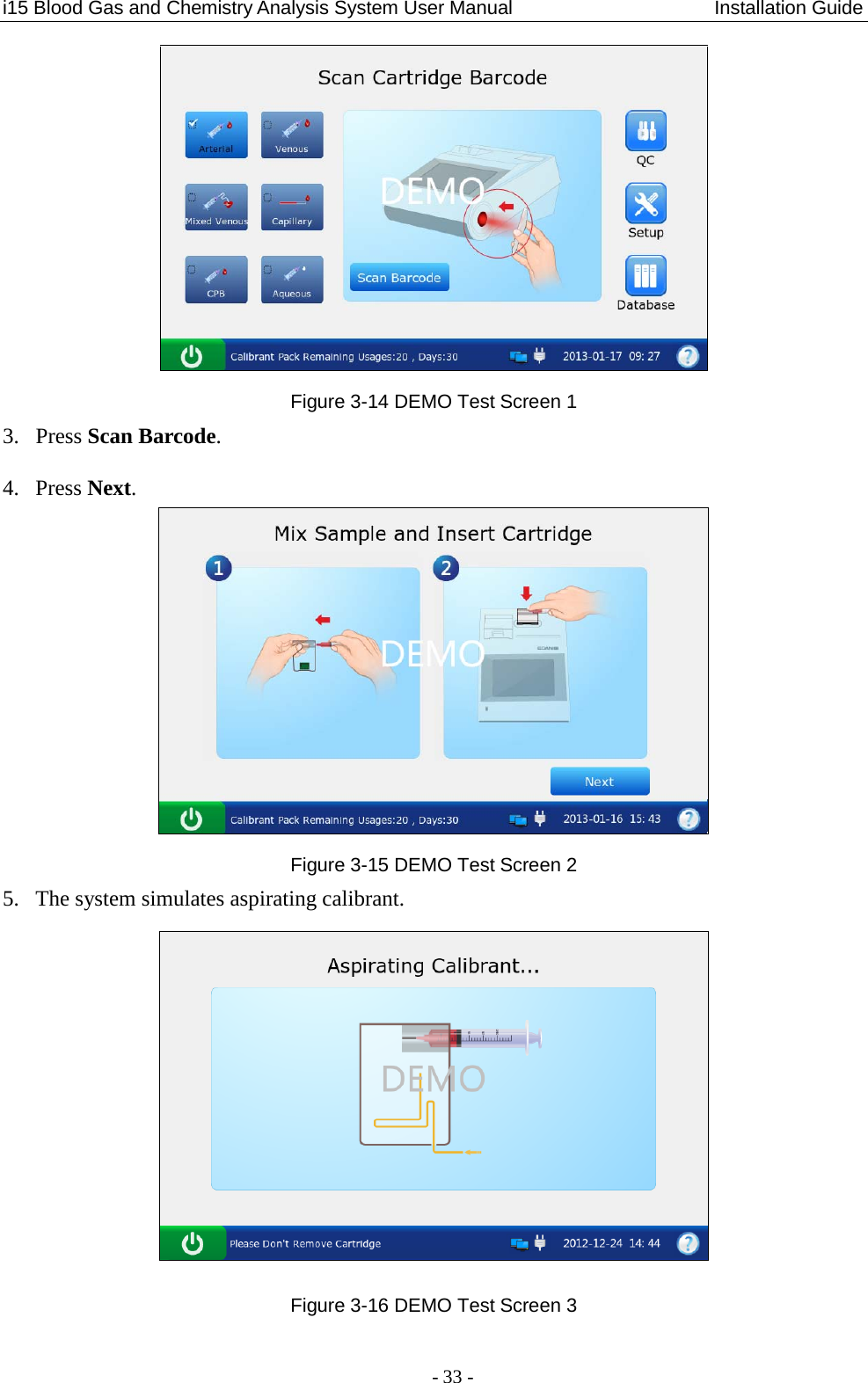
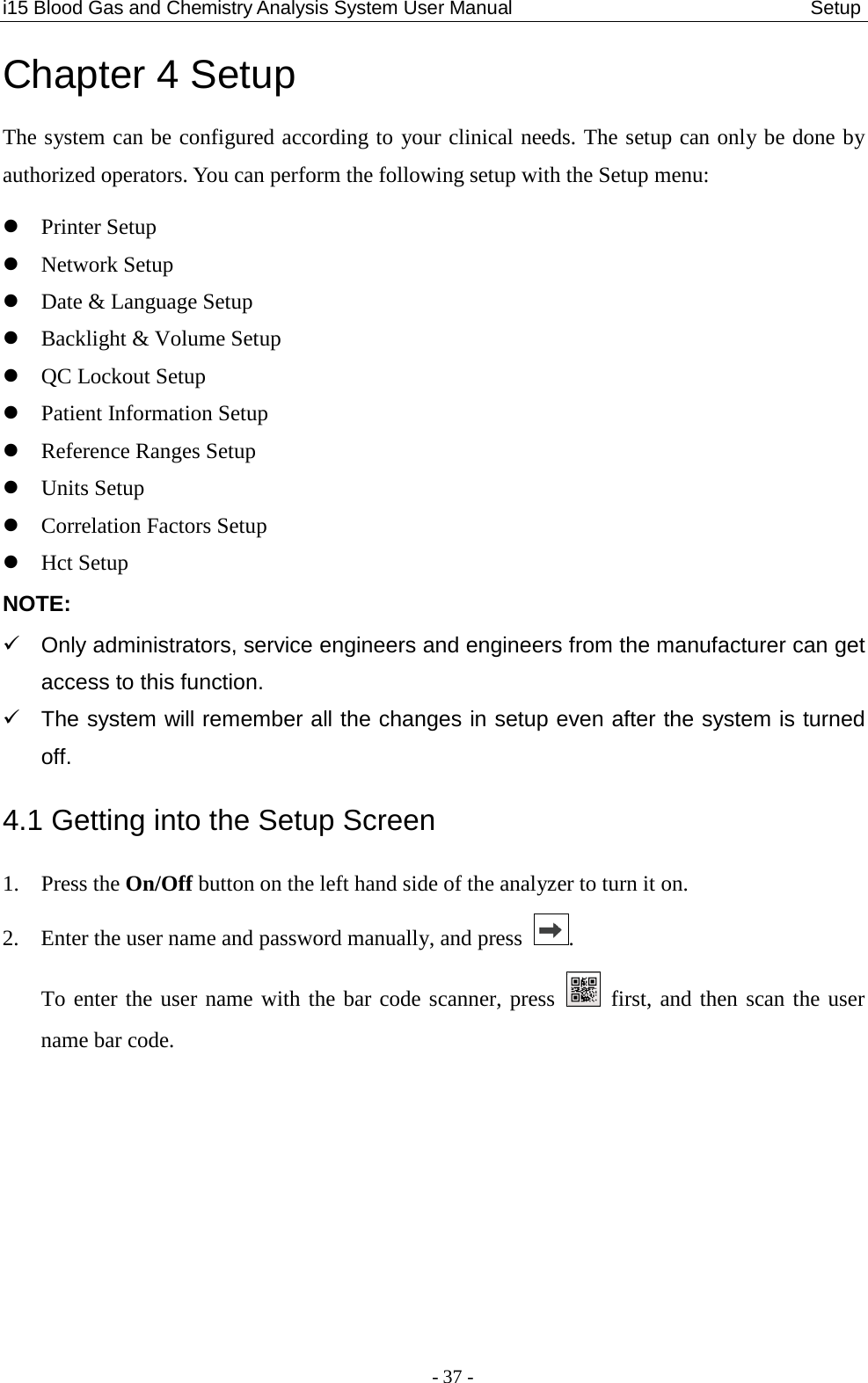
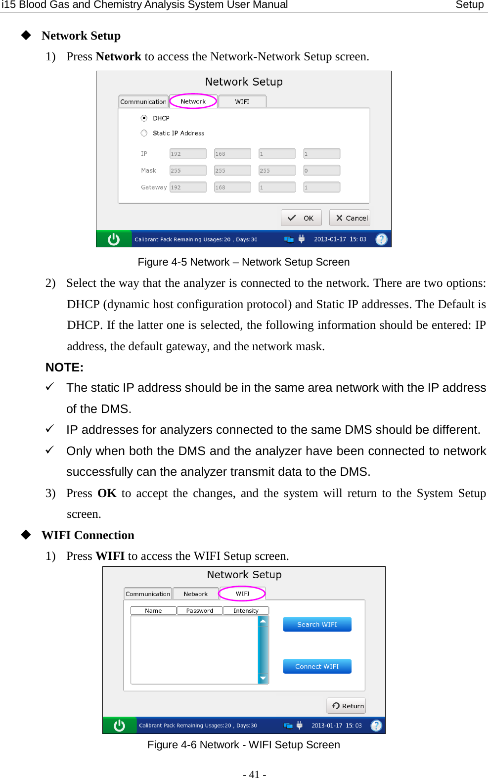
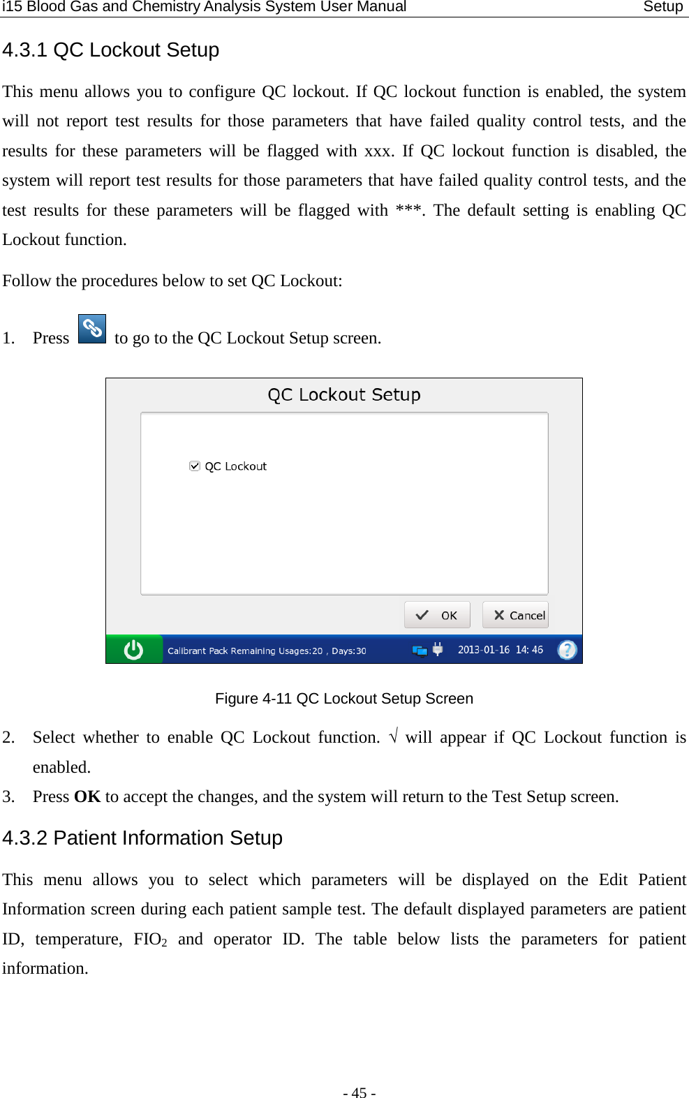
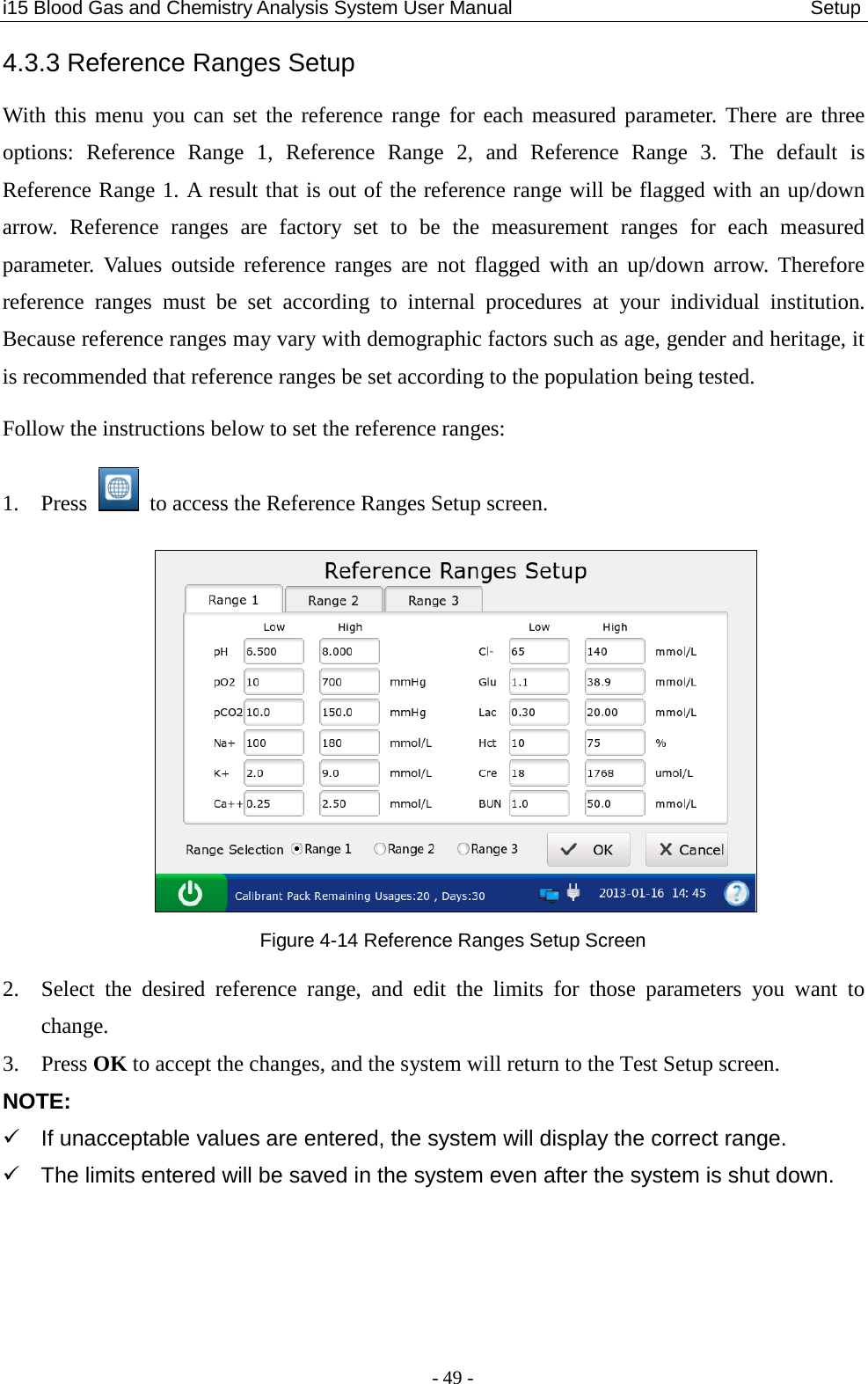
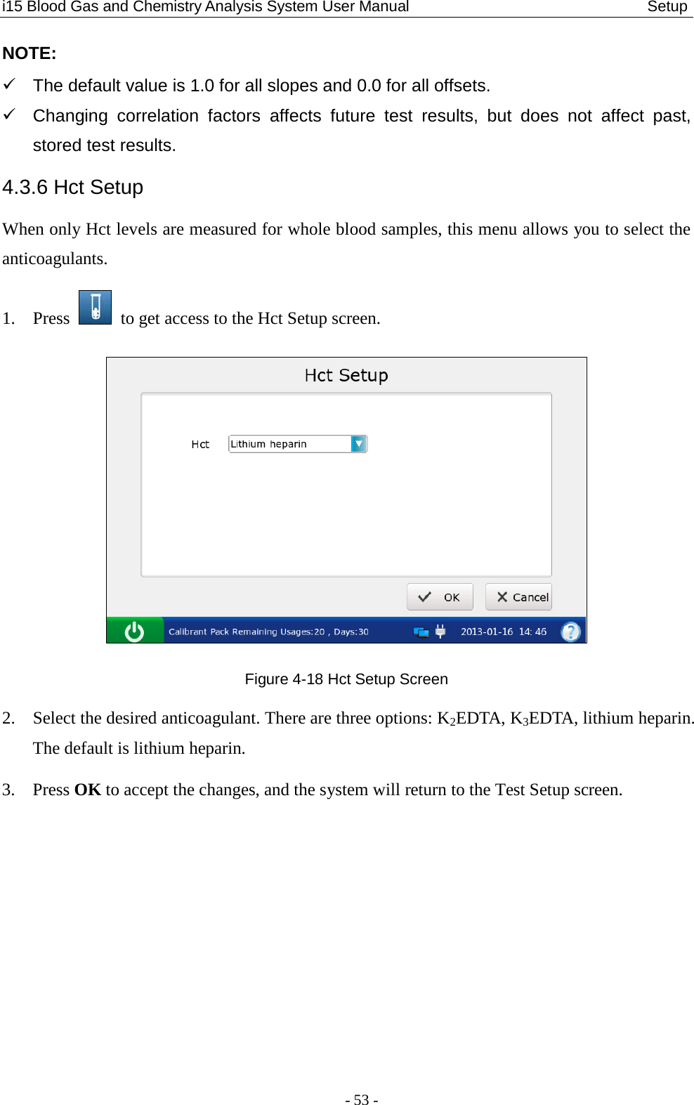
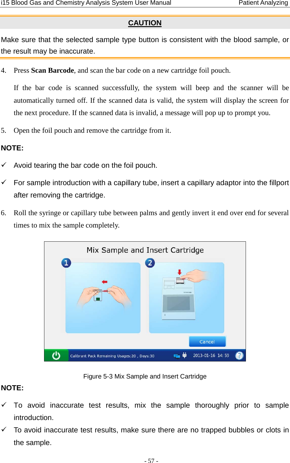
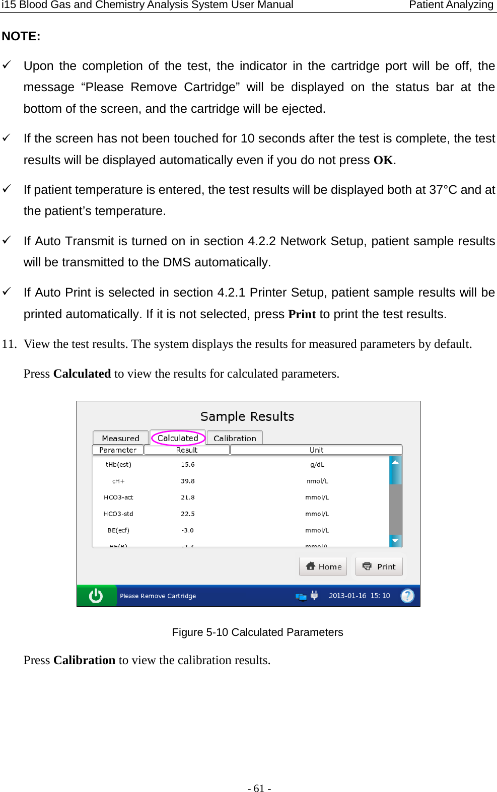
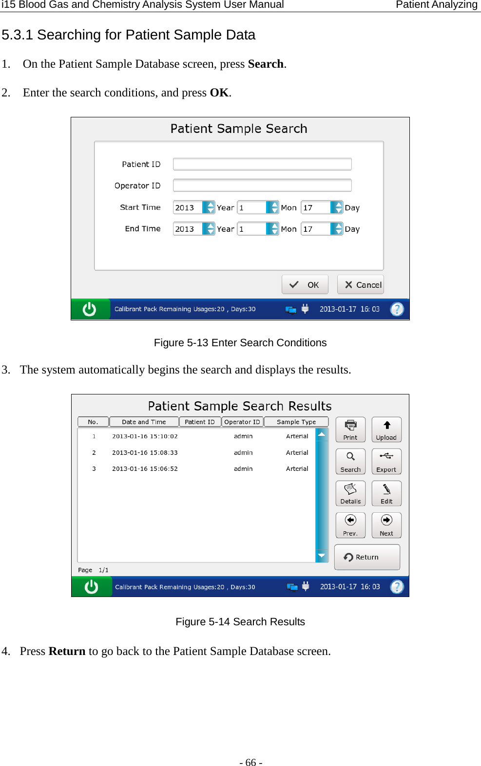
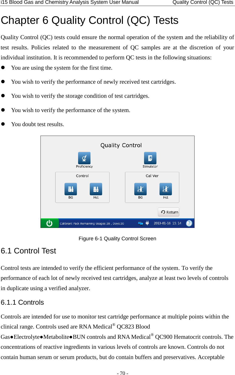
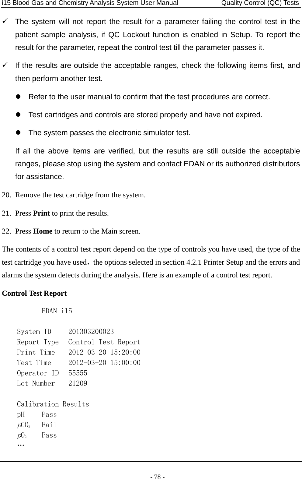
![i15 Blood Gas and Chemistry Analysis System User Manual Theory - 120 - 11.2.2 Determination of Cell Concentration Hct In whole blood, the cellular constituents, red and white blood cells and platelets do not conduct electricity, while plasma does. For a sample whose electrolyte concentration is given, the more cells, the less conductivity. The total cell concentration of the whole blood is determined from: 1) The known value of the electrolyte concentration in the calibrant. 2) The measured electrolyte concentration of the sample. 3) The measured conductivity signal generated by the calibrant. 4) The measured conductivity signal generated by the sample. CPB When samples with abnormally low protein levels are tested, the system need to use the CPB compensation algorithm. The CPB compensation algorithm is specially intended for use when samples are taken from patients on cardiopulmonary bypass. It also applies to the adult whose protein levels are abnormally low. 11.3 Equations for Calculated Parameters cH+ Hydrogen ion concentration cH+ = 10 (9 – pH) [nmol/L] HCO3-act Bicarbonate ion concentration HCO3-act = 0.0307 × pCO2 × 10(pH - 6.105) [mmol/L] HCO3-std Bicarbonate ion concentration normalized to a pCO2 40mmHg HCO3-std = 24.5 + 0.9 × A + [(A - 2.9)2 × (2.65 + 0.31 × tHb (est))] / 1000 [mmol/L] Where A = BE (B) – [0.2 × tHb (est) × (100 - sO2 (est))] / 100, tHb (est) can be entered by users, and the default value for tHb (est) is 15g/dL.](https://usermanual.wiki/EDAN-INSTRUMENTS/I15EDAN/User-Guide-2116883-Page-128.png)
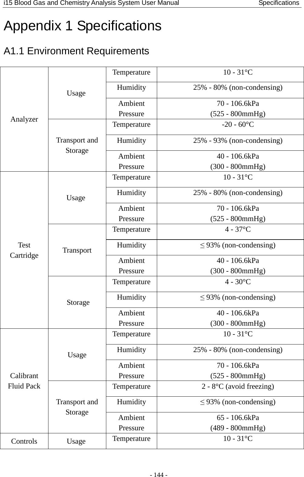
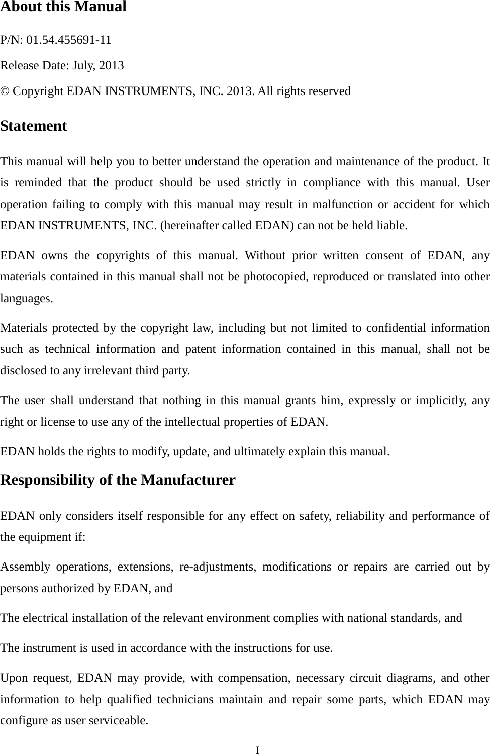
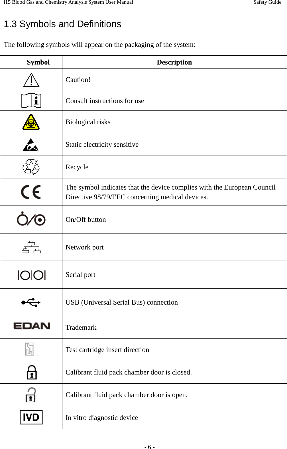
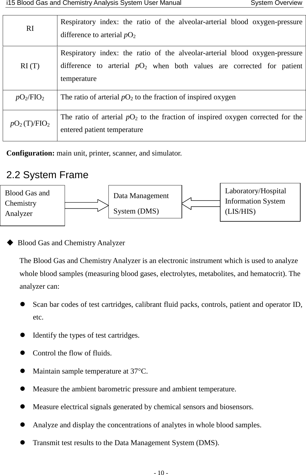
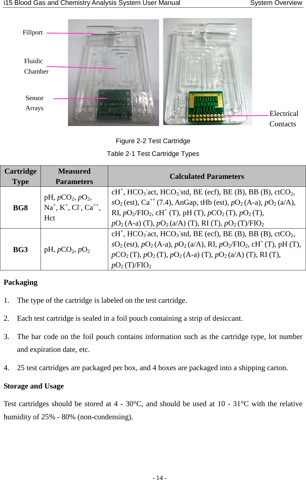
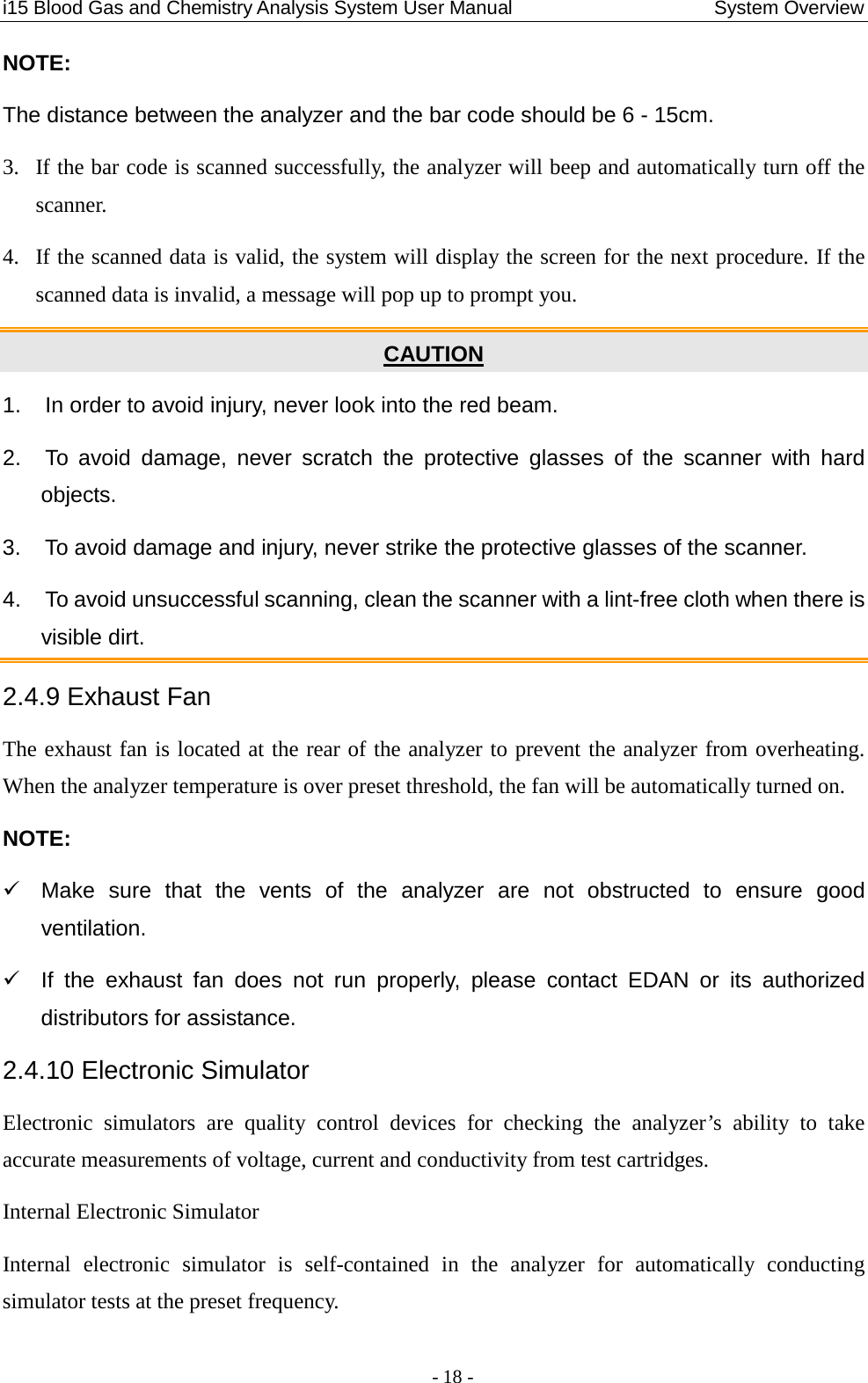
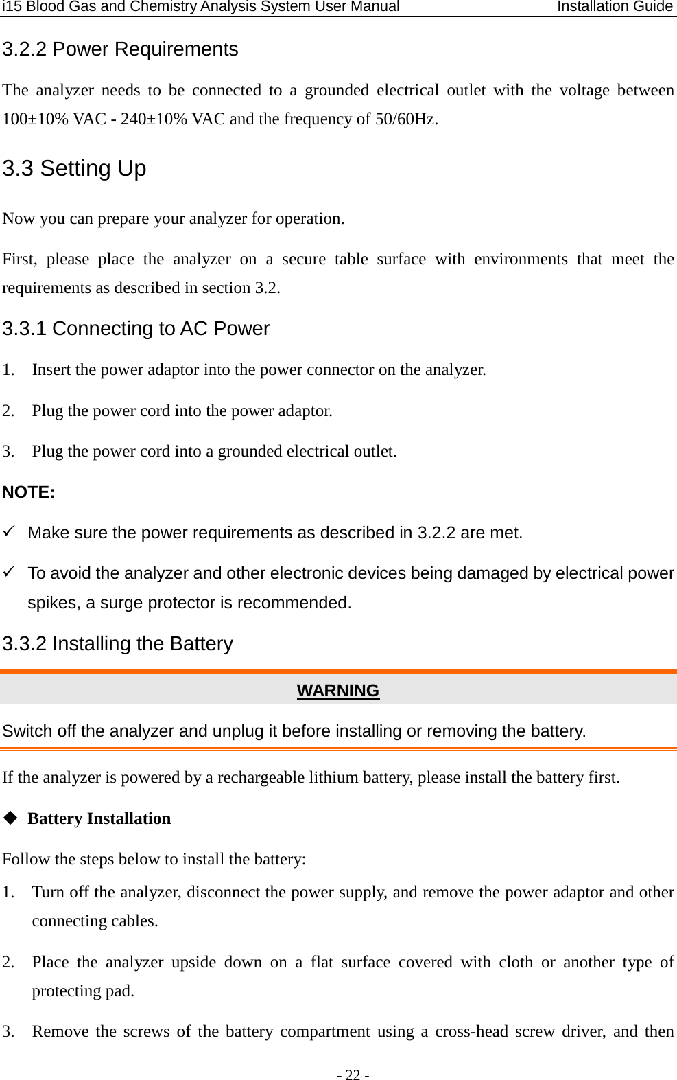
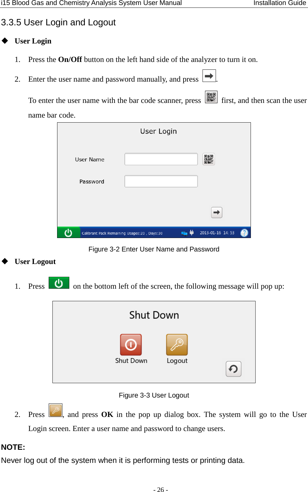
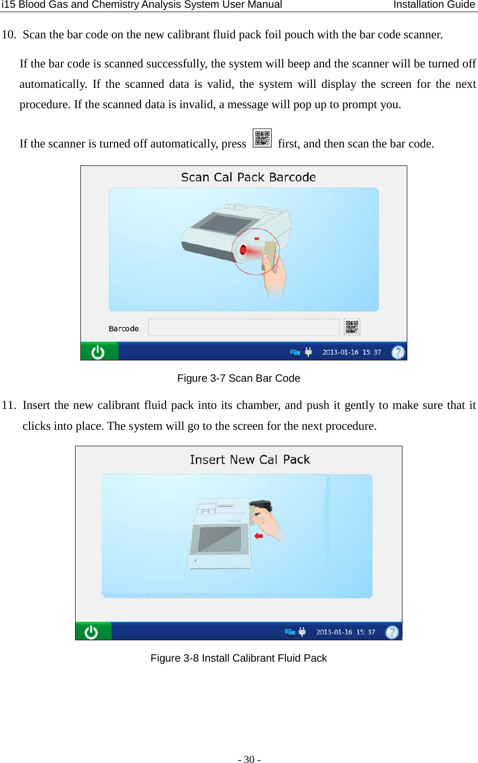
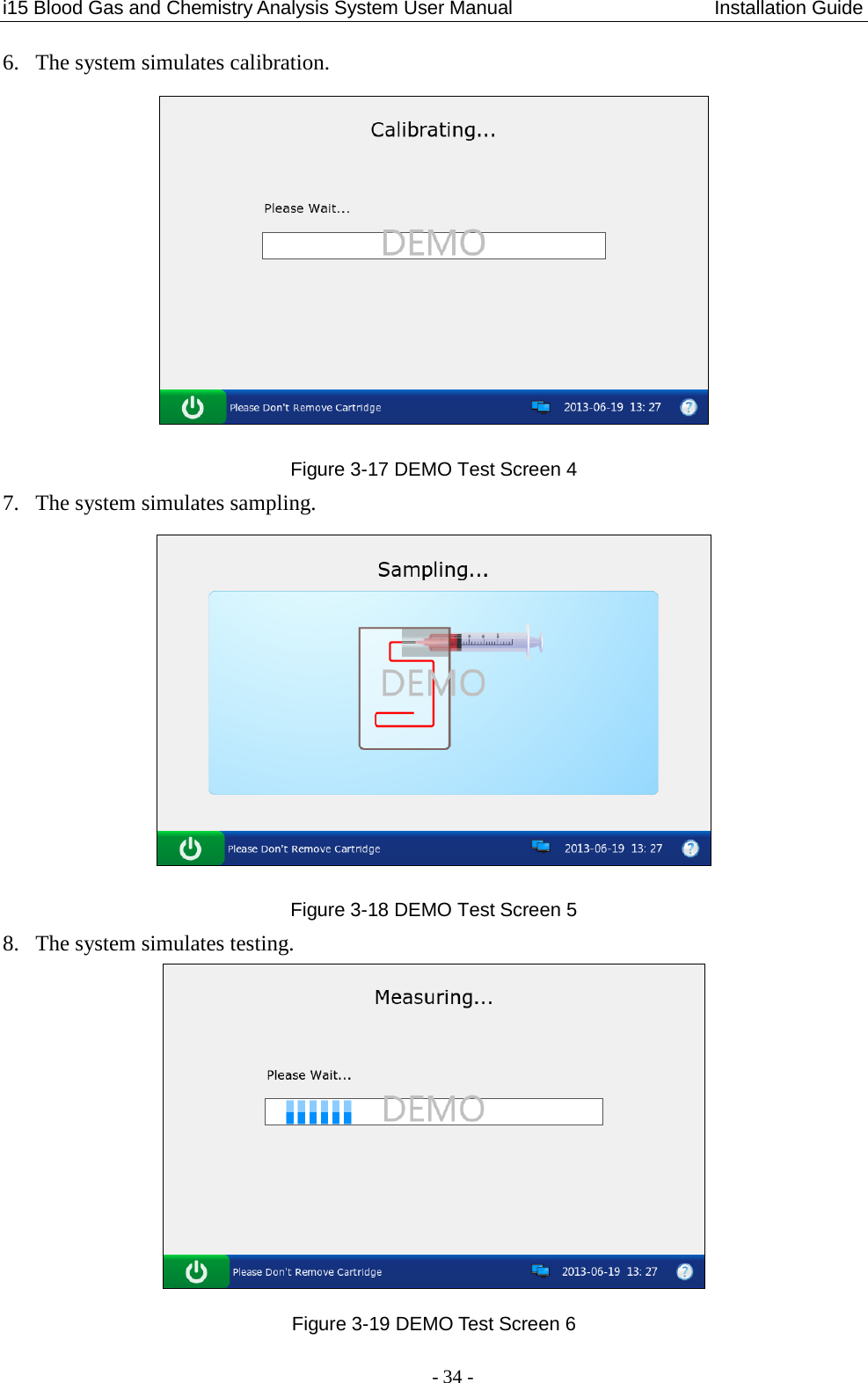
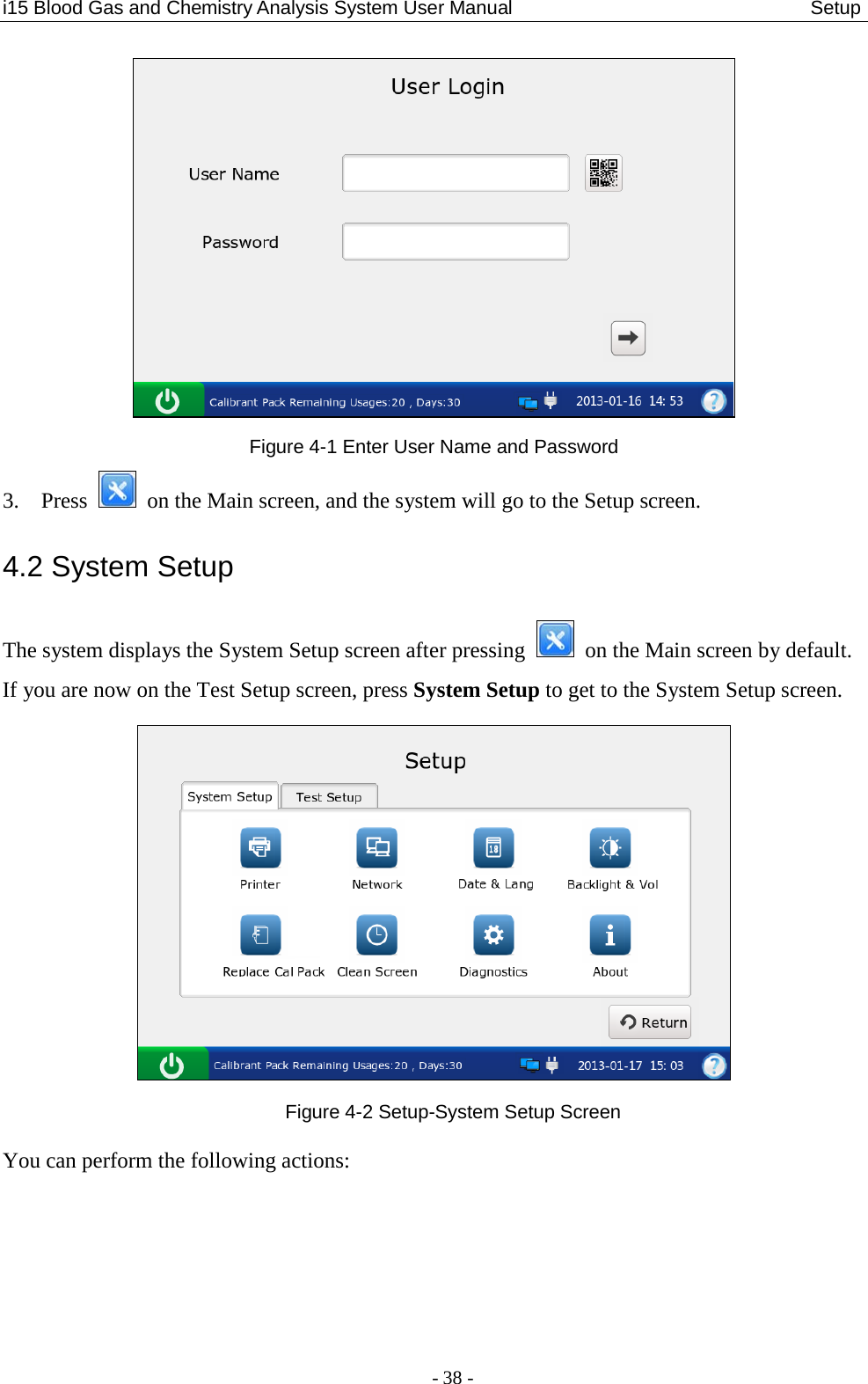
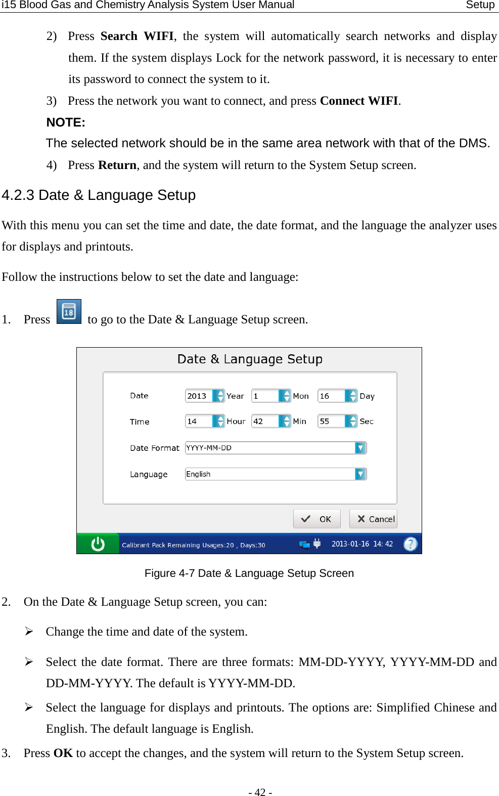
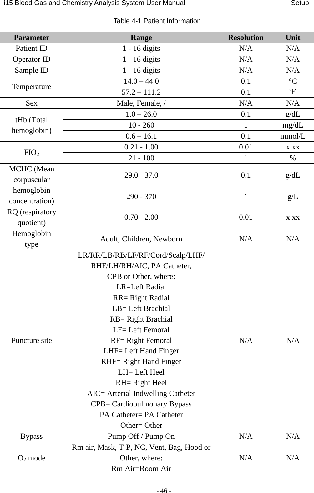
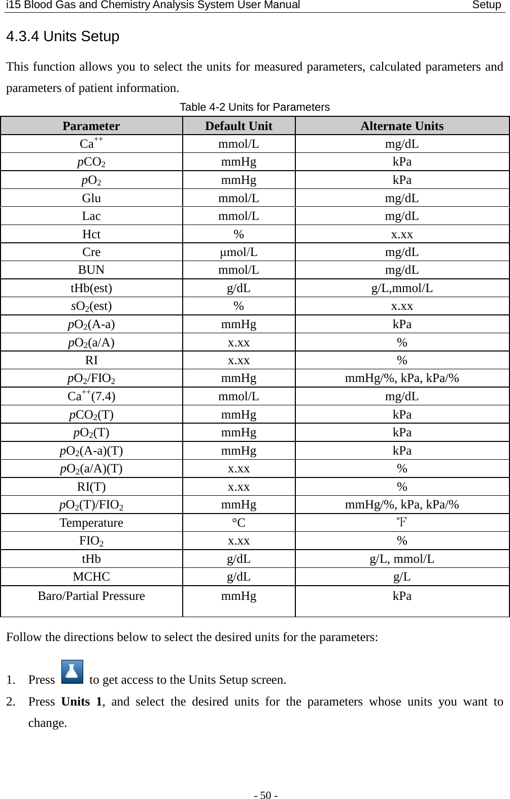
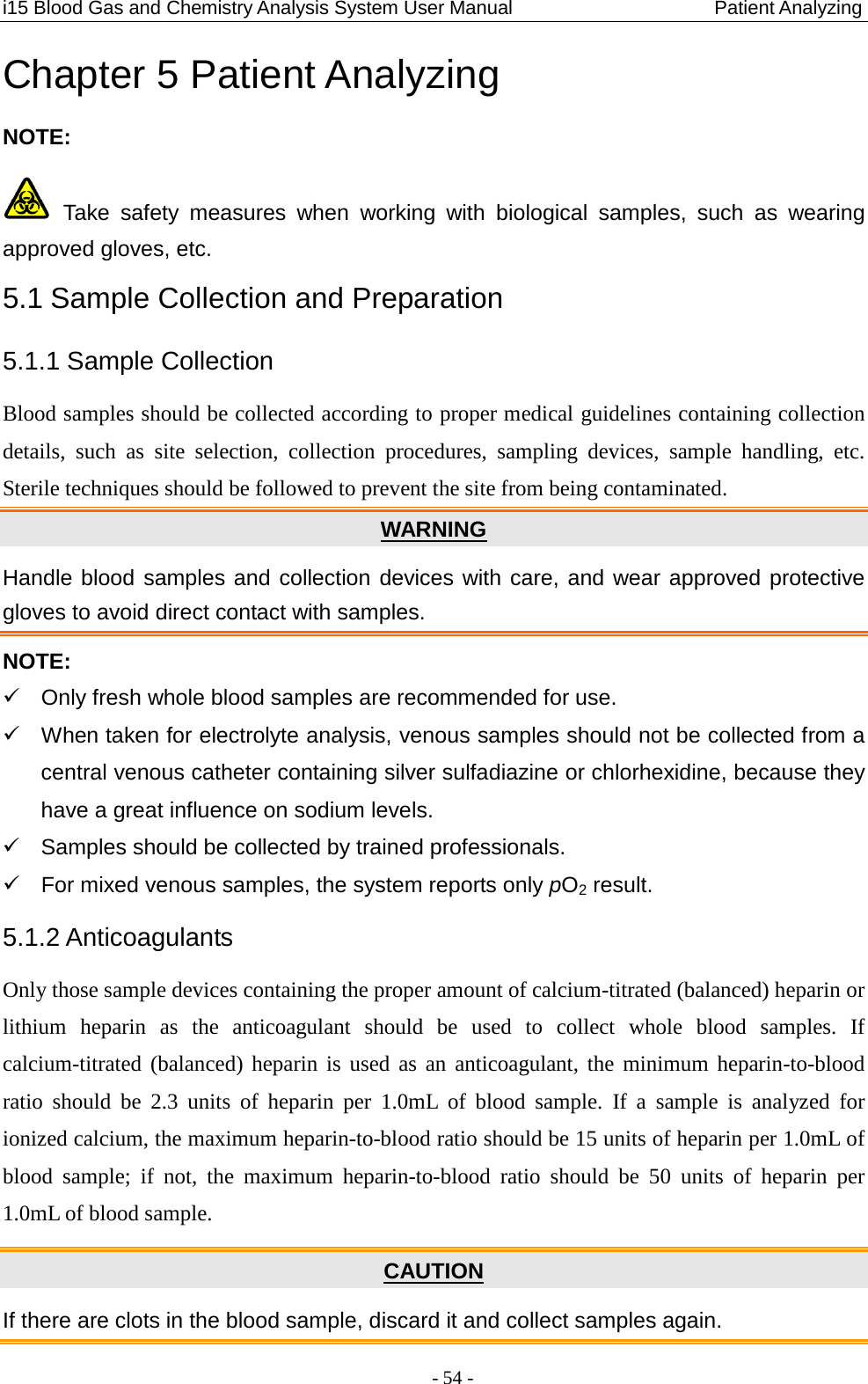
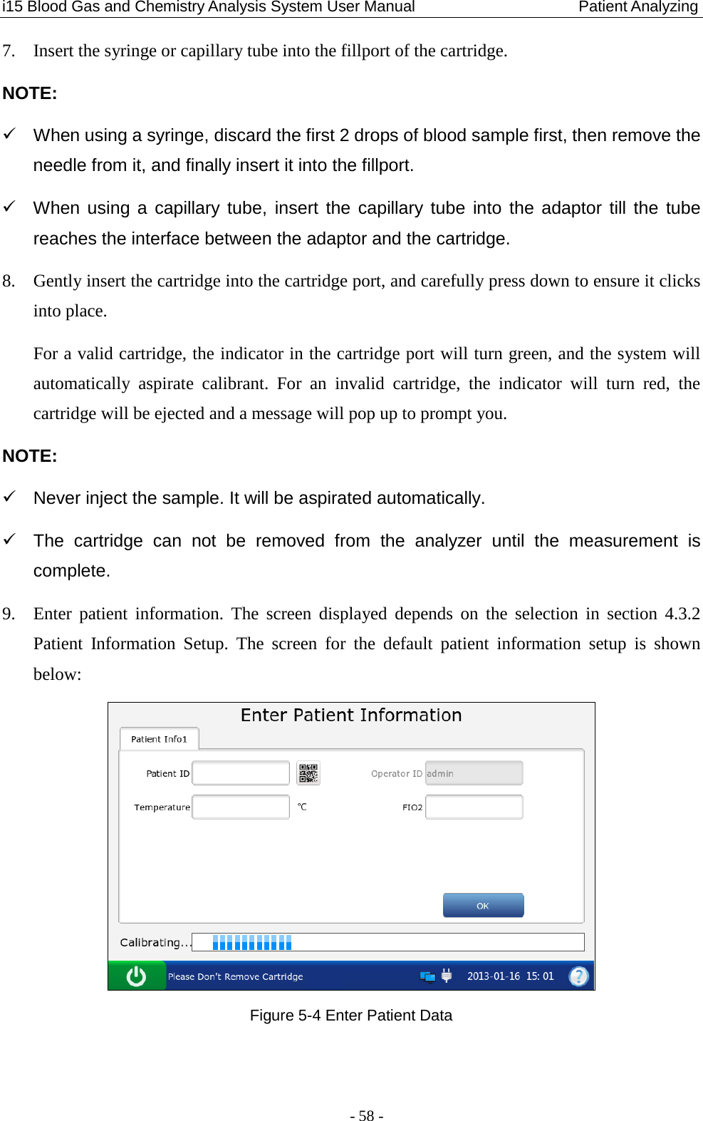
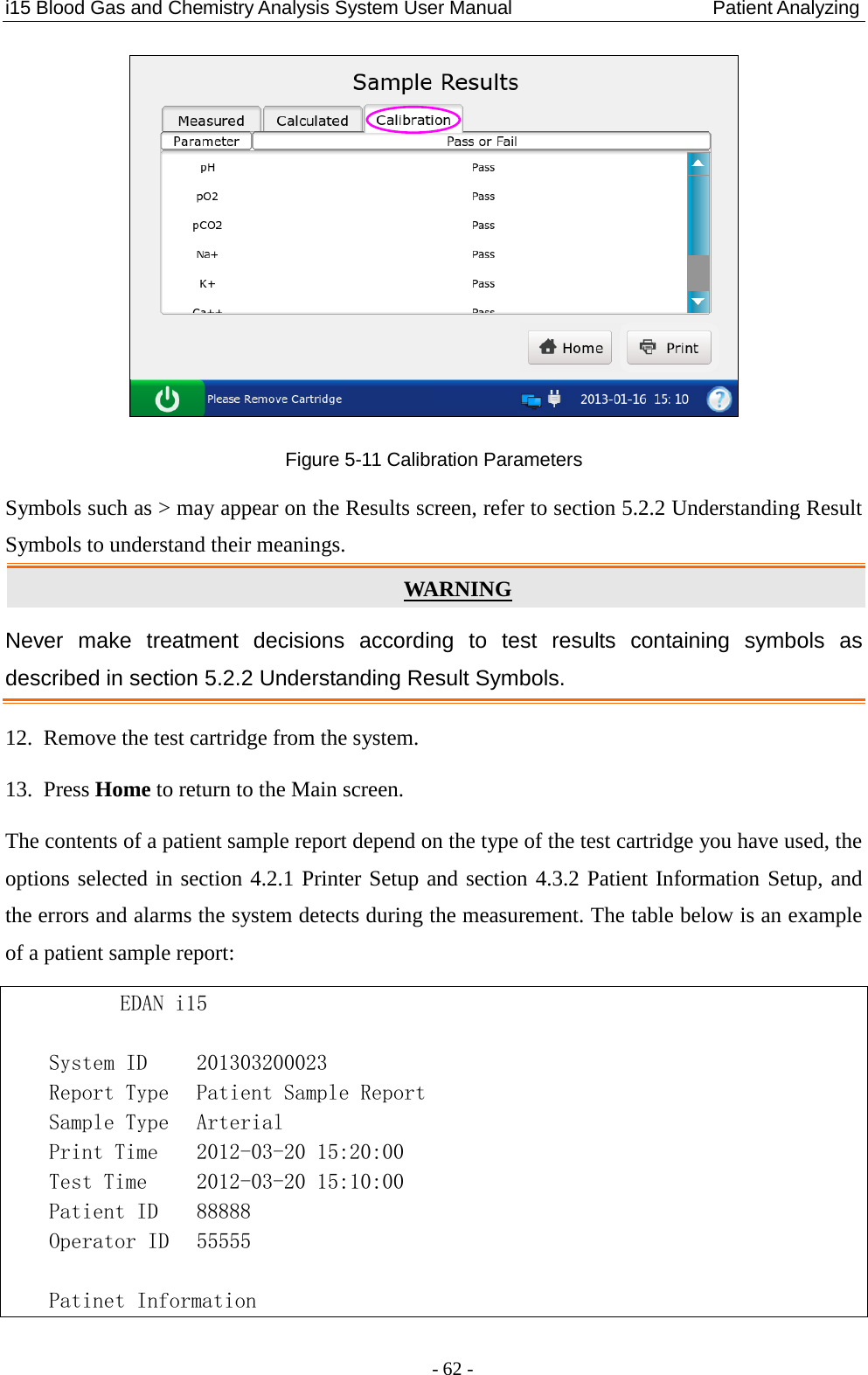
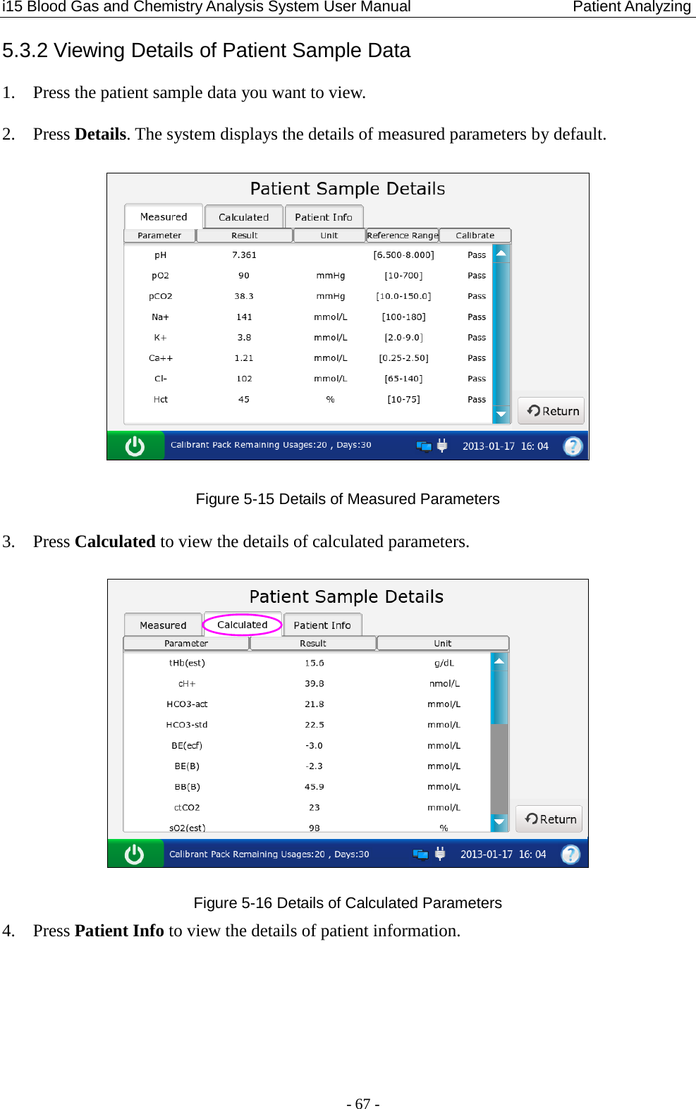
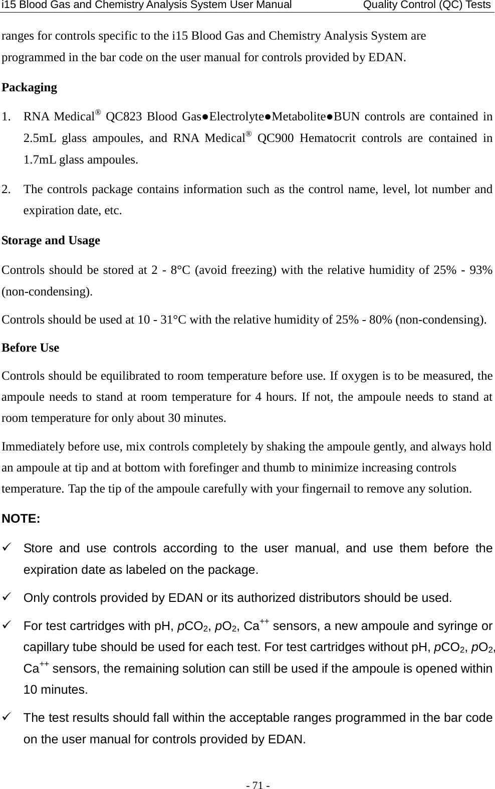
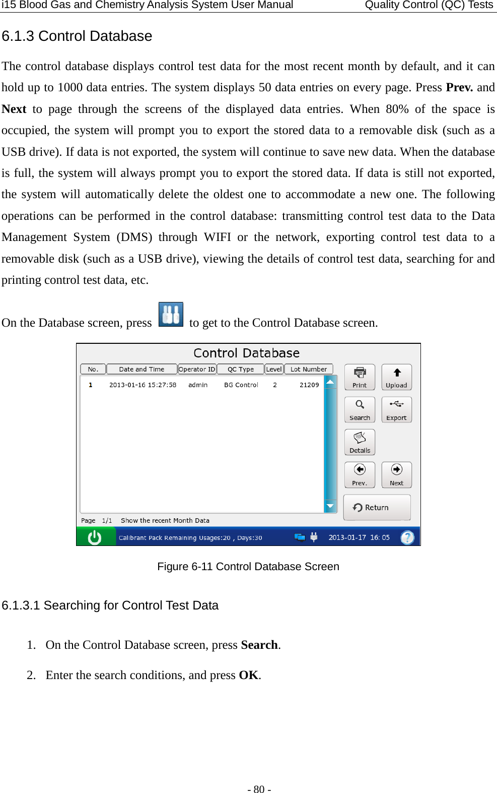
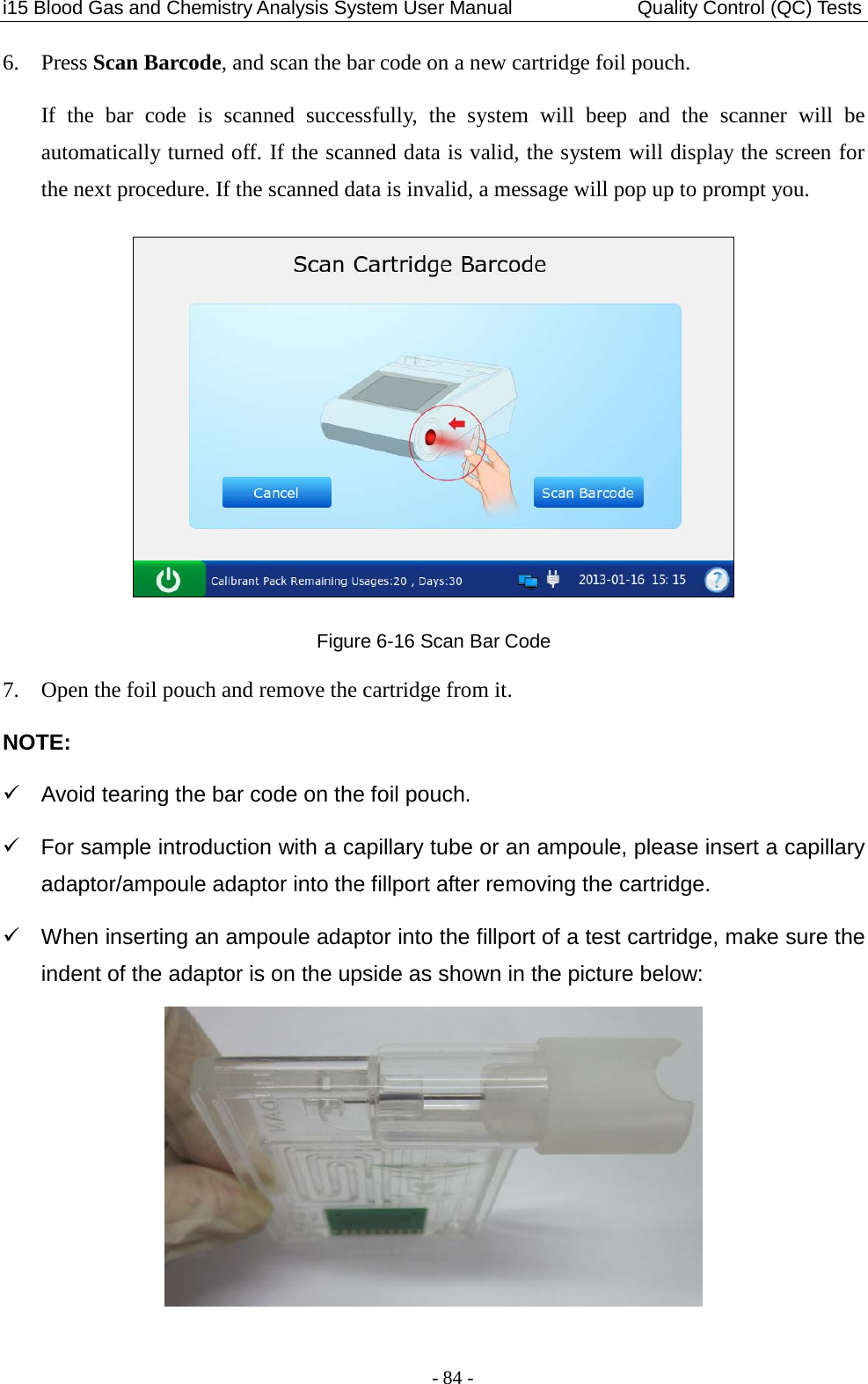
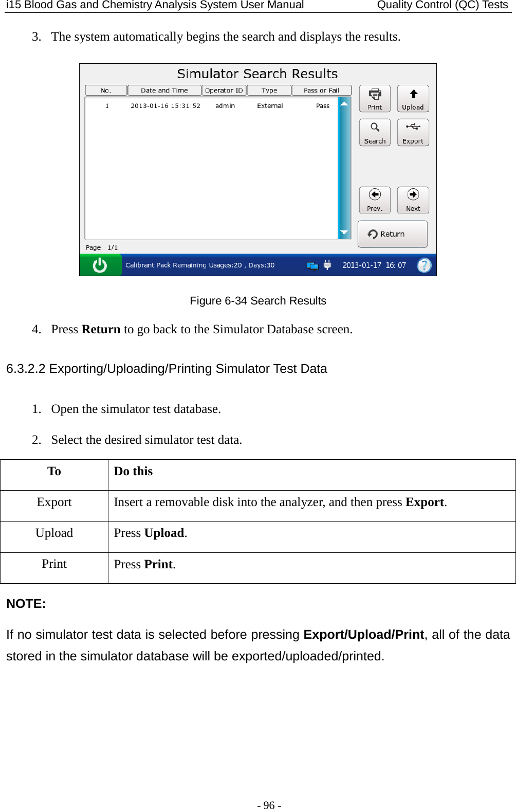
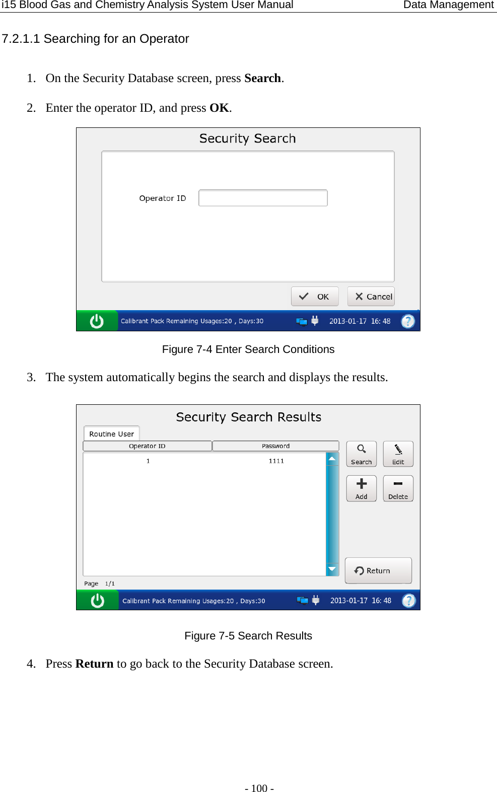
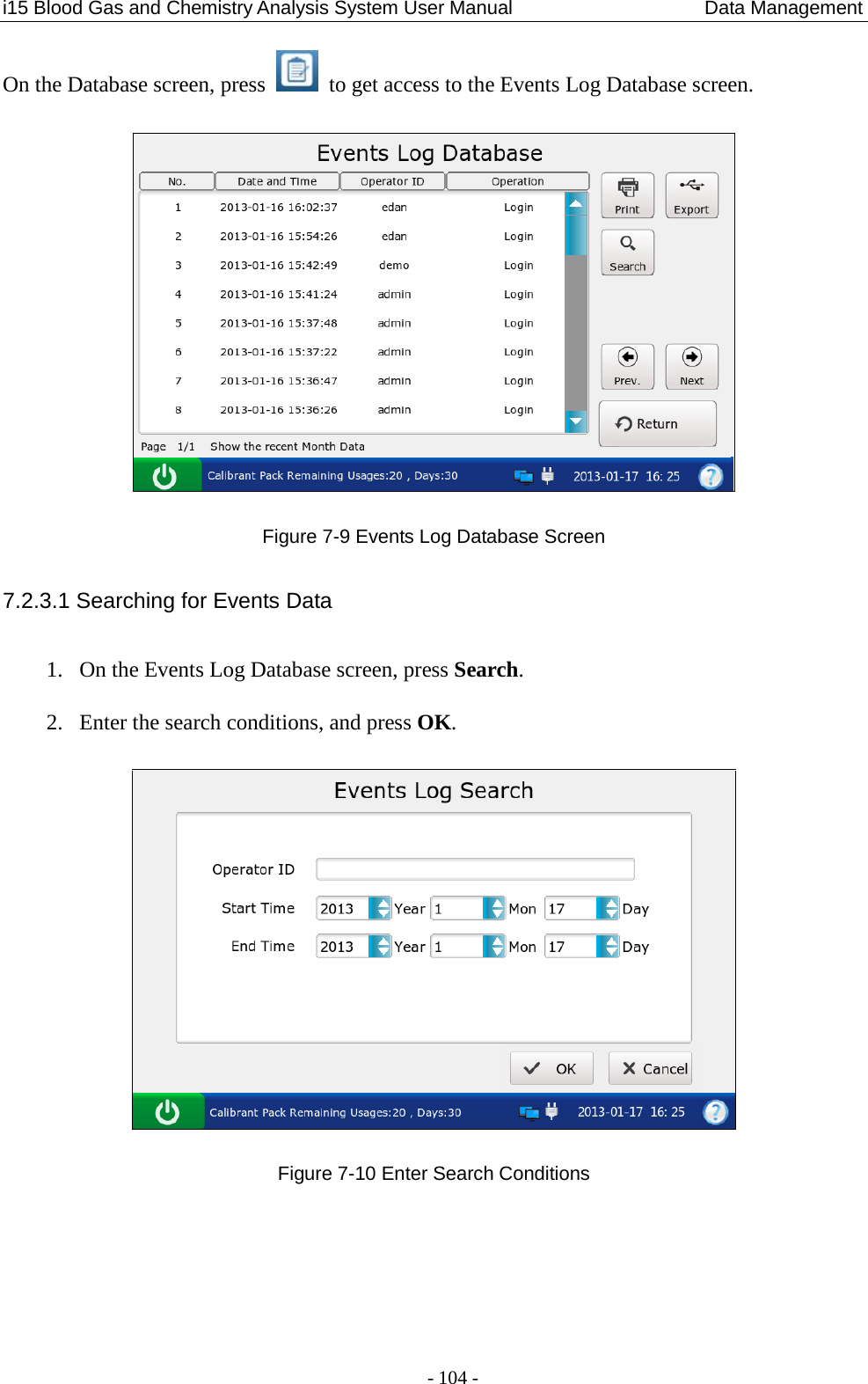
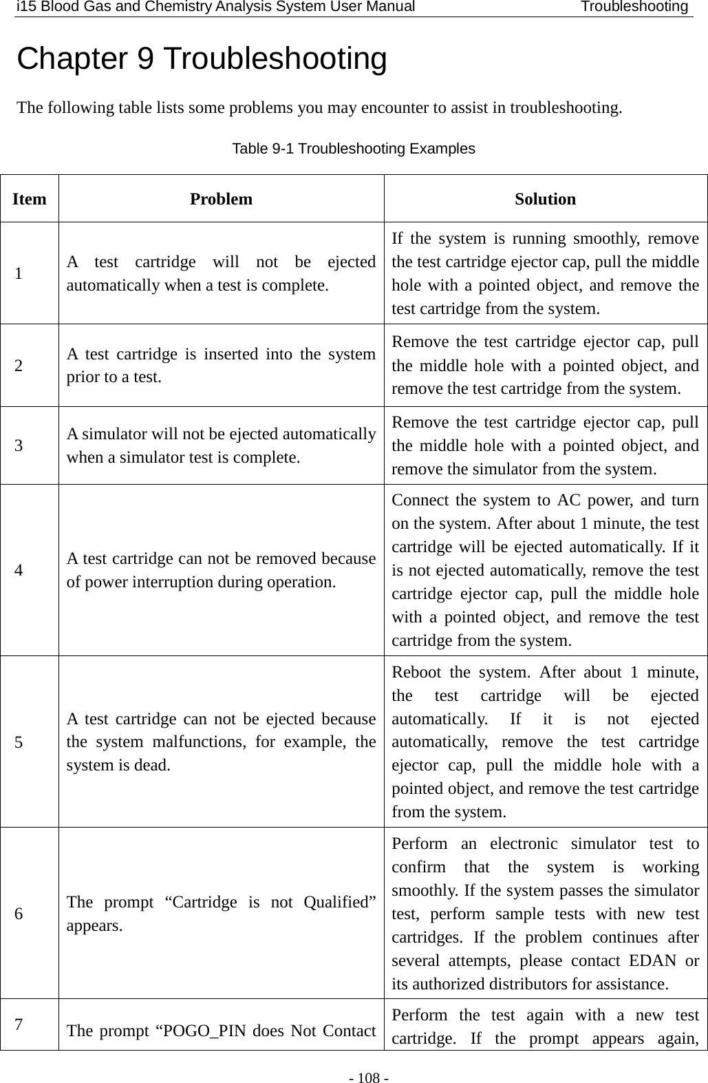
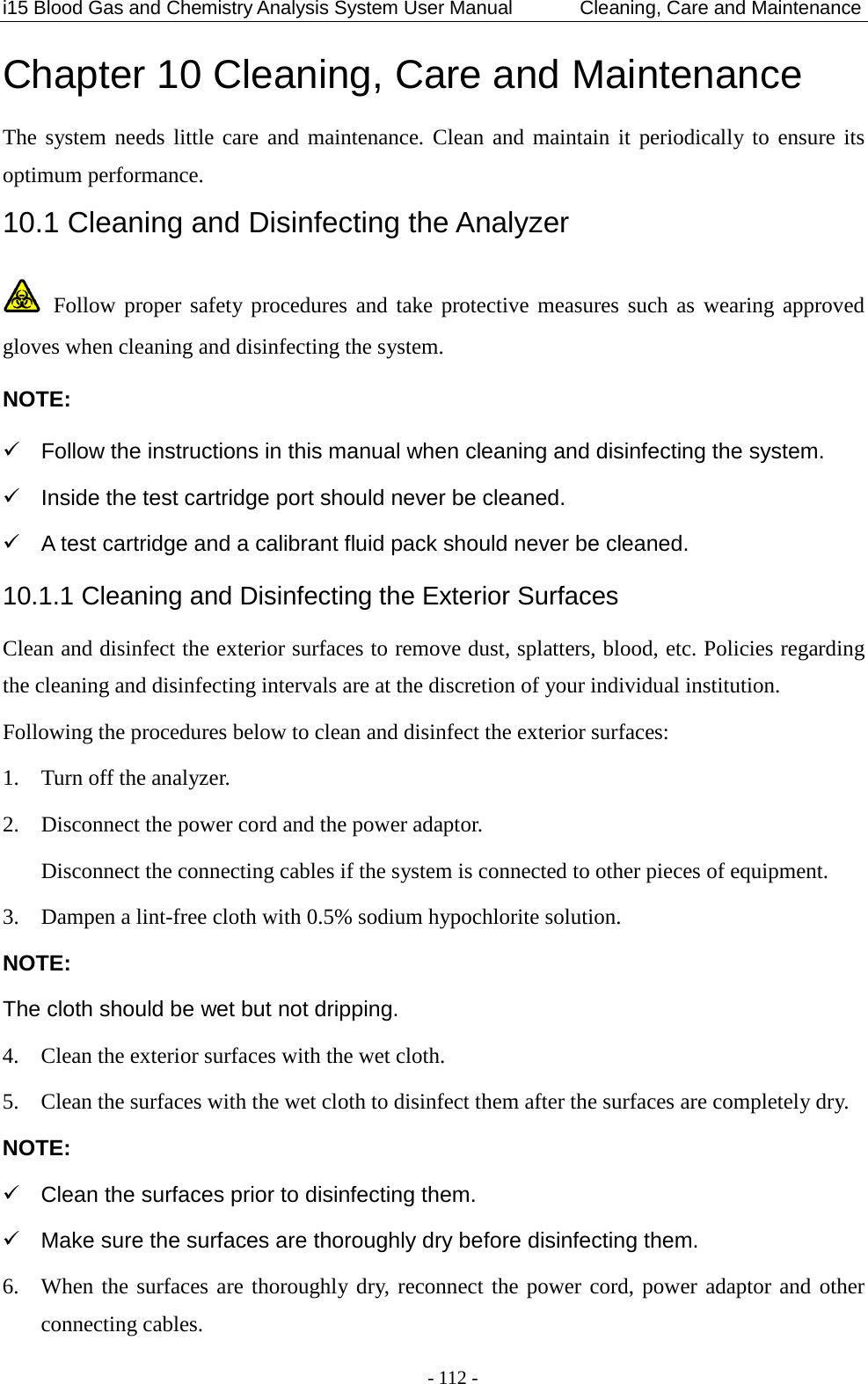
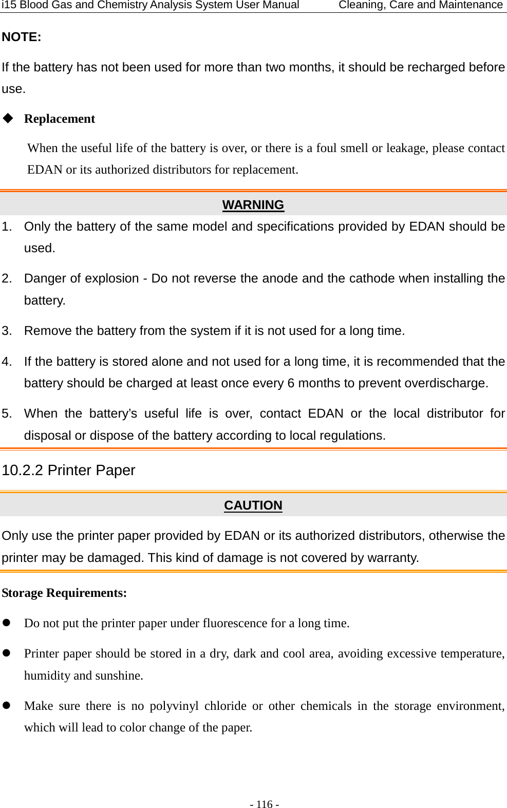
![i15 Blood Gas and Chemistry Analysis System User Manual Theory - 121 - BE (ecf) Base excess (ecf) BE (ecf) = HCO3-act - 24.8 + (16.2 × (pH - 7.40)) [mmol/L] BE (B) Base excess (B) BE (B) = (1 - 0.014 × tHb (est)) × [HCO3-act - 24.8 + (1.43 × tHb (est) + 7.7) × (pH - 7.40)] [mmol/L] Where tHb (est) can be entered by users, and the default value for tHb (est) is 15g/dL. BB (B) Buffer Base BB (B) = BE (B) + 41.7 + 0.42 × tHb (est) [mmol/L] Where tHb (est) can be entered by users, and the default value for tHb (est) is 15g/dL. ctCO2 Total carbon dioxide ctCO2 = HCO3-act + 0.0307 × pCO2 [mmol/L] Ca++ (7.4) The ionized calcium concentration of blood normalized to pH 7.4 Ca++ (7.4) = Ca++ × 10 [0.178 × (pH - 7.40)] [mmol/L] AnGap An approximation of the difference between measured cations and measured anions in the sample AnGap = (Na+ + K+) - (Cl- + HCO3-act) [mmol/L] tHb (est) An estimation of the hemoglobin contained in the sample tHb (est) = MCHC × Hct / 100 [g/dL] Where MCHC is the mean corpuscular hemoglobin concentration, and can be entered by users.](https://usermanual.wiki/EDAN-INSTRUMENTS/I15EDAN/User-Guide-2116883-Page-129.png)
![i15 Blood Gas and Chemistry Analysis System User Manual Theory - 122 - The default value for MCHC is 34g/dL. The unit for Hct is %PCV. sO2 (est) An estimation of hemoglobin oxygen saturation: a ratio of hemoglobin bound to oxygen to the total amount of hemoglobin able to bind oxygen *3 *222*3 *22( ) 100pO pOsO est pO pOααβ+×= ×+× + [%] pO2 (A-a) Alveolar-arterial oxygen tension difference pO2 (A-a) = pO2 (A) - pO2 (a) [mmHg] pO2 (a/A) Arterial-alveolar oxygen tension ratio pO2 (a/A) = pO2 (a) / pO2 (A) [mmHg] RI Respiratory index: the ratio of the alveolar-arterial blood oxygen-pressure difference to arterial pO2 RI = pO2 (A-a) / pO2 (a) pO2 / FIO2 The ratio of arterial pO2 to the fraction of inspired oxygen pO2 / FIO2 = pO2 / FIO2 [mmHg] pH (T) pH value corrected for entered patient temperature pH (T) = pH – [0.0147 + 0.0065 × (pH – 7.4)] (T – 37) cH+ (T) Hydrogen ion concentration corrected for entered patient temperature cH+ (T) = 10 (9 – pH (T)) [nmol/L]](https://usermanual.wiki/EDAN-INSTRUMENTS/I15EDAN/User-Guide-2116883-Page-130.png)
![i15 Blood Gas and Chemistry Analysis System User Manual Theory - 123 - pCO2 (T) pCO2 corrected for entered patient temperature pCO2 (T) = pCO2 × 100.019(T - 37) [mmHg] pO2 (T) pO2 corrected for entered patient temperature [mmHg] pO2 (A-a) (T) Alveolar-arterial oxygen tension difference corrected for entered patient temperature pO2 (A-a) (T) = pO2 (A) (T) - pO2 (a) (T) [mmHg] pO2 (a/A) (T) Arterial-alveolar oxygen tension ratio corrected for entered patient temperature pO2 (a/A) (T) = pO2 (a) (T) / pO2 (A) (T) [mmHg] RI (T) Respiratory index: the ratio of the alveolar-arterial blood oxygen-pressure difference to arterial pO2 when both values are corrected for patient temperature RI (T) = pO2 (A-a) (T) / pO2 (a) (T) pO2 (T)/FIO2 The ratio of arterial pO2 to the fraction of inspired oxygen corrected for the entered patient temperature pO2 (T) / FIO2 = pO2 (T) / FIO2 [mmHg]](https://usermanual.wiki/EDAN-INSTRUMENTS/I15EDAN/User-Guide-2116883-Page-131.png)
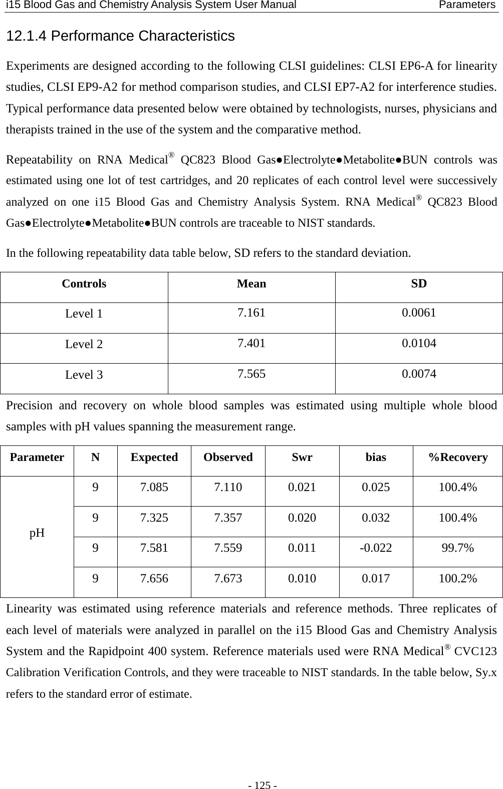
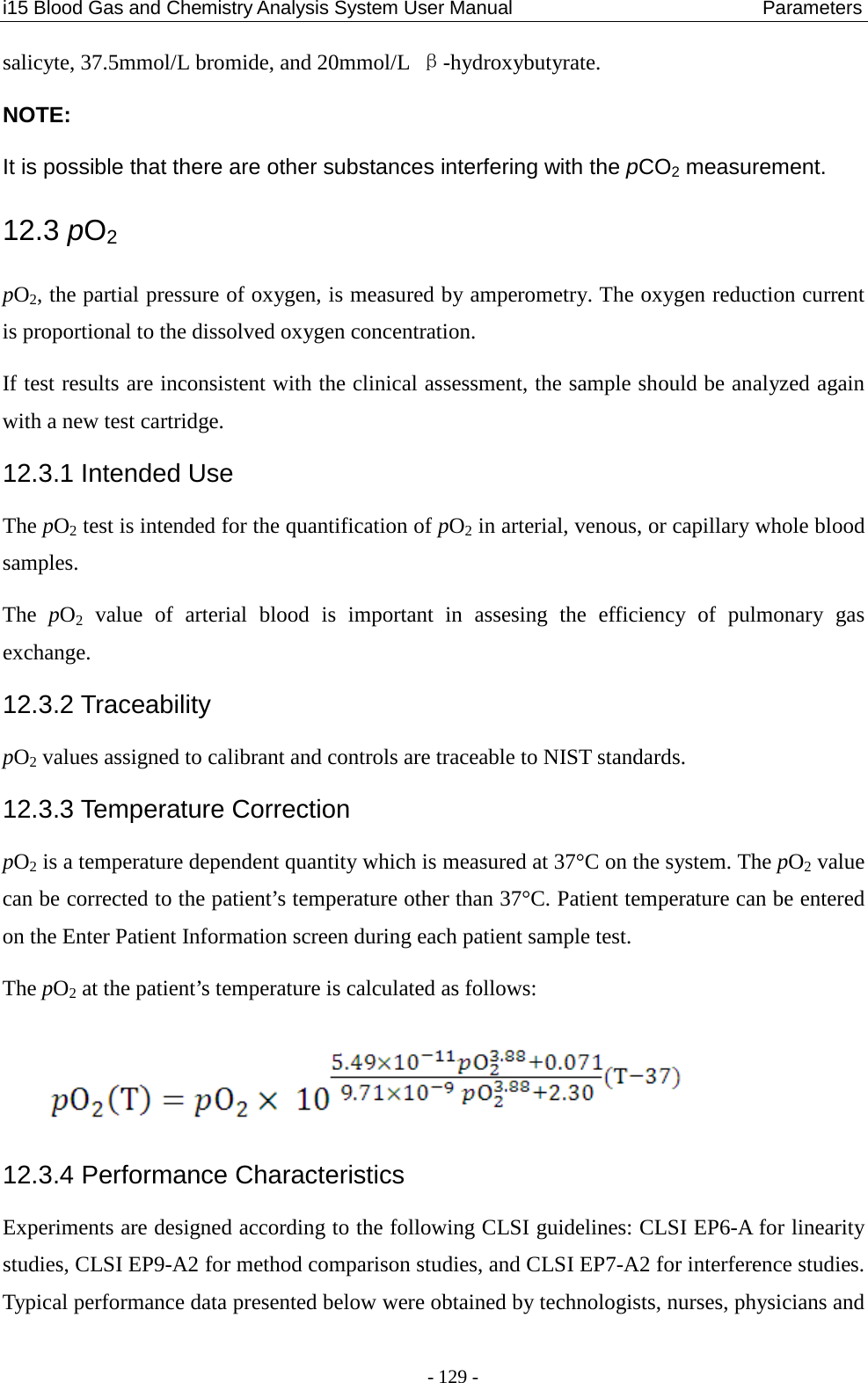
![i15 Blood Gas and Chemistry Analysis System User Manual Parameters - 124 - Chapter 12 Parameters 12.1 pH pH reflecting the acid-base status of a patient is the negative logarithm of the hydrogen ion concentration. pH is measured by potentiometry with a pH selective membrane electrode. The concentration of hydrogen ions is determined by the measured potential through the Nernst equation. If test results are inconsistent with the clinical assessment, the sample should be analyzed again with a new test cartridge. 12.1.1 Intended Use The pH test is intended for the quantification of pH in arterial, venous, or capillary whole blood samples. pH is an important clinical indicator to assess the acid-base imbalance caused by pathologic conditions, such as ventilatory dysfunction and renal inadequency. The reasons for abnormal blood pH values are: primary bicarbonate deficit - metabolic acidosis primary bicarbonate excess - metabolic alkalosis primary hypoventilation - respiratory acidosis primary hyperventilation - respiratory alkalosis 12.1.2 Traceability pH values assigned to calibrant and controls are traceable to NIST standards. 12.1.3 Temperature Correction pH is a temperature dependent quantity which is measured at 37°C on the system. The pH value can be corrected to the patient’s temperature other than 37°C. Patient temperature can be entered on the Enter Patient Information screen during each patient sample test. The pH at the patient’s temperature is calculated as follows: pH (T) = pH – [0.0147 + 0.0065(pH – 7.4)] (T – 37)](https://usermanual.wiki/EDAN-INSTRUMENTS/I15EDAN/User-Guide-2116883-Page-132.png)