EDAN INSTRUMENTS I15EDAN Blood Gas and Chemistry Analyzer User Manual
EDAN INSTRUMENTS, INC. Blood Gas and Chemistry Analyzer
User Manual

I
About this Manual
P/N: 01.54.455691-11
Release Date: July, 2013
© Copyright EDAN INSTRUMENTS, INC. 2013. All rights reserved
Statement
This manual will help you to better understand the operation and maintenance of the product. It
is reminded that the product should be used strictly in compliance with this manual. User
operation failing to comply with this manual may result in malfunction or accident for which
EDAN INSTRUMENTS, INC. (hereinafter called EDAN) can not be held liable.
EDAN owns the copyrights of this manual. Without prior written consent of EDAN, any
materials contained in this manual shall not be photocopied, reproduced or translated into other
languages.
Materials protected by the copyright law, including but not limited to confidential information
such as technical information and patent information contained in this manual, shall not be
disclosed to any irrelevant third party.
The user shall understand that nothing in this manual grants him, expressly or implicitly, any
right or license to use any of the intellectual properties of EDAN.
EDAN holds the rights to modify, update, and ultimately explain this manual.
Responsibility of the Manufacturer
EDAN only considers itself responsible for any effect on safety, reliability and performance of
the equipment if:
Assembly operations, extensions, re-adjustments, modifications or repairs are carried out by
persons authorized by EDAN, and
The electrical installation of the relevant environment complies with national standards, and
The instrument is used in accordance with the instructions for use.
Upon request, EDAN may provide, with compensation, necessary circuit diagrams, and other
information to help qualified technicians maintain and repair some parts, which EDAN may
configure as user serviceable.
II
Terms Used in this Manual
This guide is designed to give key concepts on safety precautions.
WARNING
A WARNING label advises against certain actions or situations that could result in personal
injury or death.
CAUTION
A CAUTION label advises against actions or situations that could damage equipment, produce
inaccurate data, or invalidate a procedure.
NOTE
A NOTE provides useful information regarding a function or a procedure.
III
Table of Contents
Chapter 1 Safety Guide ................................................................................................................ 1
1.1 Intended Use....................................................................................................................... 1
1.2 Warnings and Cautions ....................................................................................................... 1
1.2.1 Safety Warnings ..................................................................................................... 1
1.2.2 Safety Cautions ...................................................................................................... 5
1.3 Symbols and Definitions .................................................................................................... 6
Chapter 2 System Overview ......................................................................................................... 8
2.1 Introduction ........................................................................................................................ 8
2.2 System Frame ................................................................................................................... 10
2.3 Analyzer Appearance ....................................................................................................... 12
2.4 System Parts ..................................................................................................................... 13
2.4.1 Thermal Printer .................................................................................................... 13
2.4.2 Test Cartridge ....................................................................................................... 13
2.4.3 Power Indicator .................................................................................................... 15
2.4.4 LCD Screen and Touch Screen ............................................................................ 15
2.4.5 I/O Ports ............................................................................................................... 16
2.4.6 On/Off Button ...................................................................................................... 16
2.4.7 Calibrant Fluid Pack ............................................................................................. 16
2.4.8 Bar Code Scanner ................................................................................................. 17
2.4.9 Exhaust Fan .......................................................................................................... 18
2.4.10 Electronic Simulator........................................................................................... 18
2.4.11 Peripherics .......................................................................................................... 19
2.5 Configuration ................................................................................................................... 20
2.5.1 Standard Configuration ........................................................................................ 20
2.5.2 Options ................................................................................................................. 20
Chapter 3 Installation Guide ...................................................................................................... 21
3.1 Unpacking Inspection....................................................................................................... 21
3.2 Installation Requirements................................................................................................. 21
3.2.1 Environmental Requirements ............................................................................... 21
3.2.2 Power Requirements ............................................................................................ 22
3.3 Setting Up ........................................................................................................................ 22
3.3.1 Connecting to AC Power ...................................................................................... 22
3.3.2 Installing the Battery ............................................................................................ 22
3.3.3 Installing the Printer Paper ................................................................................... 24
3.3.4 Turning On/Off the Analyzer ............................................................................... 25
3.3.5 User Login and Logout ........................................................................................ 26
3.3.6 Setting the Date and Time .................................................................................... 27
3.4.7 Viewing Training Videos ...................................................................................... 27
3.4.8 Replacing a Calibrant Fluid Pack ......................................................................... 28
3.3.9 DEMO Test .......................................................................................................... 32
IV
3.3.10 Connecting Peripherics ...................................................................................... 35
Chapter 4 Setup ........................................................................................................................... 37
4.1 Getting into the Setup Screen ........................................................................................... 37
4.2 System Setup .................................................................................................................... 38
4.2.1 Printer Setup ......................................................................................................... 39
4.2.2 Network Setup ...................................................................................................... 40
4.2.3 Date & Language Setup ....................................................................................... 42
4.2.4 Backlight & Volume Setup ................................................................................... 43
4.2.5 Diagnostics ........................................................................................................... 43
4.2.6 About the Analyzer ............................................................................................... 44
4.3 Test Setup ......................................................................................................................... 44
4.3.1 QC Lockout Setup ................................................................................................ 45
4.3.2 Patient Information Setup .................................................................................... 45
4.3.3 Reference Ranges Setup ....................................................................................... 49
4.3.4 Units Setup ........................................................................................................... 50
4.3.5 Correlation Factors Setup ..................................................................................... 52
4.3.6 Hct Setup .............................................................................................................. 53
Chapter 5 Patient Analyzing ...................................................................................................... 54
5.1 Sample Collection and Preparation .................................................................................. 54
5.1.1 Sample Collection ................................................................................................ 54
5.1.2 Anticoagulants ...................................................................................................... 54
5.1.3 Collection Devices and Volume ........................................................................... 55
5.1.4 Notes .................................................................................................................... 55
5.2 Patient Analyzing ............................................................................................................. 56
5.2.1 Procedures for Patient Analyzing ......................................................................... 56
5.2.2 Understanding Result Symbols ............................................................................ 64
5.3 Patient Sample Database .................................................................................................. 65
5.3.1 Searching for Patient Sample Data ...................................................................... 66
5.3.2 Viewing Details of Patient Sample Data .............................................................. 67
5.3.3 Editing Patient Information Data ......................................................................... 68
5.3.4 Exporting/Uploading/Printing Patient Sample Data ............................................ 69
Chapter 6 Quality Control (QC) Tests ...................................................................................... 70
6.1 Control Test ...................................................................................................................... 70
6.1.1 Controls ................................................................................................................ 70
6.1.2 Procedures for Control Test.................................................................................. 72
6.1.3 Control Database .................................................................................................. 80
6.2 Proficiency Test ................................................................................................................ 83
6.2.1 Procedures for Proficiency Test ........................................................................... 83
6.2.2 Proficiency Database ............................................................................................ 89
6.3 Simulator Test .................................................................................................................. 92
6.3.1 Procedures for External Simulator Test ............................................................... 92
6.3.2 Simulator Database .............................................................................................. 94
V
Chapter 7 Data Management ..................................................................................................... 98
7.1 Introduction ...................................................................................................................... 98
7.2 Databases.......................................................................................................................... 98
7.2.1 Security Database ................................................................................................. 99
7.2.2 Diagnosis Database ............................................................................................ 103
7.2.3 Events Log Database .......................................................................................... 103
7.2.4 Backup ............................................................................................................... 106
Chapter 8 Online Update .......................................................................................................... 107
8.1 Introduction .................................................................................................................... 107
8.2 Procedures for Online Update ........................................................................................ 107
Chapter 9 Troubleshooting ....................................................................................................... 108
Chapter 10 Cleaning, Care and Maintenance ......................................................................... 112
10.1 Cleaning and Disinfecting the Analyzer ...................................................................... 112
10.1.1 Cleaning and Disinfecting the Exterior Surfaces ............................................. 112
10.1.2 Cleaning and Disinfecting the Screen .............................................................. 113
10.1.3 Cleaning the Printer Head ................................................................................ 114
10.2 Care and Maintenance .................................................................................................. 115
10.2.1 Recharging and Replacement of Battery .......................................................... 115
10.2.2 Printer Paper ..................................................................................................... 116
10.2.3 Maintenance of the Analyzer ........................................................................... 117
Chapter 11 Theory ..................................................................................................................... 118
11.1 Measurement Method ................................................................................................... 118
11.2 Determination of Test Results ...................................................................................... 119
11.2.1 Determination of the Analyte Concentration ................................................... 119
11.2.2 Determination of Cell Concentration ............................................................... 120
11.3 Equations for Calculated Parameters ........................................................................... 120
Chapter 12 Parameters ............................................................................................................. 124
12.1 pH ................................................................................................................................. 124
12.1.1 Intended Use..................................................................................................... 124
12.1.2 Traceability ....................................................................................................... 124
12.1.3 Temperature Correction .................................................................................... 124
12.1.4 Performance Characteristics............................................................................. 125
12.1.5 Interfering Substances ...................................................................................... 126
12.2 pCO2 ............................................................................................................................. 126
12.2.1 Intended Use..................................................................................................... 126
12.2.2 Traceability ....................................................................................................... 127
12.2.3 Temperature Correction .................................................................................... 127
12.2.4 Performance Characteristics............................................................................. 127
12.2.5 Interfering Substances ...................................................................................... 128
12.3 pO2 ............................................................................................................................... 129
12.3.1 Intended Use..................................................................................................... 129
VI
12.3.2 Traceability ....................................................................................................... 129
12.3.3 Temperature Correction .................................................................................... 129
12.3.4 Performance Characteristics............................................................................. 129
12.3.5 Interfering Substances ...................................................................................... 131
12.4 Sodium (Na+) ............................................................................................................... 131
12.4.1 Intended Use..................................................................................................... 131
12.4.2 Traceability ....................................................................................................... 132
12.4.3 Performance Characteristics............................................................................. 132
12.4.4 Interfering Substances ...................................................................................... 133
12.5 Potassium (K+) ............................................................................................................. 133
12.5.1 Intended Use..................................................................................................... 134
12.5.2 Traceability ....................................................................................................... 134
12.5.3 Performance Characteristics............................................................................. 134
12.5.4 Interfering Substances ...................................................................................... 135
12.6 Ionized Calcium (Ca++) ................................................................................................ 136
12.6.1 Intended Use..................................................................................................... 136
12.6.2 Traceability ....................................................................................................... 136
12.6.3 Performance Characteristics............................................................................. 136
12.6.4 Interfering Substances ...................................................................................... 137
12.7 Chloride (Cl-) ............................................................................................................... 138
12.7.1 Intended Use..................................................................................................... 138
12.7.2 Traceability ....................................................................................................... 138
12.7.3 Performance Characteristics............................................................................. 139
12.7.4 Interfering Substances ...................................................................................... 140
12.8 Hematocrit (Hct) .......................................................................................................... 140
12.8.1 Intended Use..................................................................................................... 141
12.8.2 Traceability ....................................................................................................... 141
12.8.3 Performance Characteristics............................................................................. 141
12.8.4 Interfering Substances ...................................................................................... 142
Chapter 13 Warranty and Service ........................................................................................... 143
13.1 Warranty ....................................................................................................................... 143
13.2 Contact Information ..................................................................................................... 143
Appendix 1 Specifications ........................................................................................................ 144
A1.1 Environment Requirements ......................................................................................... 144
A1.2 Analyzer Specifications ............................................................................................... 145
A1.3 Performance Specifications ......................................................................................... 145
A1.4 Printer .......................................................................................................................... 145
A1.5 Rechargeable Battery .................................................................................................. 146
A1.6 Safety Specifications ................................................................................................... 146
Appendix 2 Measurement Ranges ........................................................................................... 147
A2.1 Measurement Ranges for Measured Parameters ......................................................... 147
A2.2 Measurement Ranges for Calculated Parameters ........................................................ 147

VII
Appendix 3 Reference Ranges .................................................................................................. 148
Appendix 4 EMC Information ................................................................................................. 149
Appendix 5 FCC Information .................................................................................................. 153
A5.1 FCC Statement ............................................................................................................ 153
A5.2 FCC RF Radiation Exposure Statement ...................................................................... 153
Appendix 6 Order List .............................................................................................................. 154

i15 Blood Gas and Chemistry Analysis System User Manual Safety Guide
- 1 -
Chapter 1 Safety Guide
1.1 Intended Use
i15 Blood Gas and Chemistry Analysis System (including Blood Gas and Chemistry Analyzer,
Calibrant Fluid Pack, Test Cartridge) is a portable, automated system that measures blood gases,
blood chemistries, and hematocrit in whole blood samples. The system is intended for use only
by trained technologists, nurses, physicians and therapists. It is intended for use in a laboratory
environment, near patient or point-of-care settings. By timely providing test results, the system
helps the medical professionals make faster decisions about patient treatment, and thus improves
the quality of patient care.
1.2 Warnings and Cautions
In order to use the system safely and effectively, and avoid possible dangers caused by improper
operation, please read through the user manual and be sure to be familiar with all functions of the
system and proper operation procedures before use. Always keep this manual with the analyzer.
Please pay attention to the following warning and caution information.
1.2.1 Safety Warnings
NOTE:
The reliability of the analyzer and the safety of operators are considered during product
design and production. The following safety and preventive measures should be carried
out:
WARNING
Safety Warnings
1. The analyzer is not intended for treatment.
2. The analyzer is not intended for home use.
3. Do not use the analyzer if it is damaged or defective.
4. The analyzer should be installed by a qualified service engineer. Do not try to access
the interior of the analyzer. Only authorized service personnel could remove the
analyzer enclosure.
5. To avoid electrical shock, never modify the analyzer’s AC power circuits.

i15 Blood Gas and Chemistry Analysis System User Manual Safety Guide
- 2 -
6. The analyzer is intended for use only by trained technologists, nurses, physicians
and therapists. Operators should be familiar with the contents of this user manual
before operation.
WARNING
7. The results given by the system should be examined based on the overall clinical
condition of the patient, and should not be a substitute for regular checking.
8. To ensure grounding reliability, only connect the system to a hospital-grade power
receptacle.
9. Connect the analyzer to a grounded socket and make certain that the mains supply
meets the requirements specified in the user manual.
10. Do not exceed the maximum permitted load when using multiple portable
socket-outlets to supply the system.
11. SHOCK HAZARD - Do not attempt to connect or disconnect a power cord with wet
hands. Make certain that your hands are clean and dry before touching a power cord.
12. If you have any questions about the power adaptor or the power cord, use the battery
but not the AC power supply. Prior to using AC power supply, inspection of the power
adaptor and the power cord is recommended. If it is necessary, consult EDAN or its
authorized distributors for service.
13. The analyzer is not waterproof. Do not use it in locations where water or any liquid
leakage may occur.
14. Do not cast any fluid onto the system surface, as fluid seepage into the electrical
circuitry may cause excessive leakage current or system failure.
15. Do not spray cleaning fluids on the system, as this may force cleaning fluid into the
system and damage electronic components. It is also possible for solvent fumes to
build up and form flammable gases or damage internal components.
16. To avoid the possibility of electrostatic shock and damage to the system, avoid using
aerosol spray cleansers on the analyzer screen.
17. EXPLOSION HAZARD – The analyzer is not suitable for use in the presence of a
flammable anesthetic mixture with oxygen or other flammable compounds.

i15 Blood Gas and Chemistry Analysis System User Manual Safety Guide
- 3 -
18. To avoid electrical shock, never use the system in altitude exceeding 3,000 meters
above sea level.
WARNING
19. Periodically have the safety of the system checked by a qualified service engineer.
20. Only accessories supplied or recommended by the manufacturer should be used.
Otherwise, performance and electric shock protection can not be guaranteed.
21. Blood samples should be collected according to proper medical guidelines which
contains collection details, such as site selection, collection procedures, sample
handling, etc. Sterile techniques should be followed to prevent the site from being
contaminated.
22. Handle blood samples and collection devices with care, and wear approved
protective gloves to avoid direct contact with samples.
23. To avoid electrical shock and damage to the system, turn off the analyzer and
disconnect the analyzer from the AC power source before cleaning and disinfecting.
24. To avoid the airinlet and airoutlet of the fan being blocked by foreign matters, check
them regularly.
25. To avoid being injured, never touch the stitch of a calibrant fluid pack.
26. To avoid being hurt, never look into the scanner beam light.
27. The system is for in vitro diagnostic use only.
28. Perform quality control (QC) tests regularly to make certain that the system works
smoothly.
29. The disposable test cartridges should only be used a single time.
30. Never replace a calibrant fluid pack when the analyzer is off.
31. A calibrant fluid pack is intended for single use only. If a calibrant fluid pack is
removed from the system, it can not be inserted into the system again.
32. Test cartridges are biohazardous waste after use. They should be disposed of
according to local regulatory guidelines.

i15 Blood Gas and Chemistry Analysis System User Manual Safety Guide
- 4 -
33.
WARNING
Never use an external electronic simulator under electromagnetic environment,
and never touch it by hand during an external simulator test.
34. Do not use the analyzer after its life cycle, and it should be disposed of according to
local regulations after its life cycle.
Battery Care
35. Improper operation may cause the lithium battery (hereinafter called battery) to be
hot, ignited or explode, and it may lead to the declination of the battery capacity. It is
necessary to read the user manual carefully and pay attention to warning messages.
36. The battery of the same model and specifications provided by the manufacturer
should be used.
37. Danger of explosion - Do not reverse the anode and the cathode when installing the
battery.
38. Do not heat or splash the battery or throw it into fire or water.
39. When there is leakage or a foul smell, stop using the battery immediately. If your skin
or clothes come into contact with the leakage liquid, cleanse it with clean water at
once. If the leakage liquid splashes into your eyes, do not wipe them. Irrigate them
with clean water first and seek medical assistance immediately.
40. The analyzer and accessories are to be disposed of according to local regulations
after their useful lives. Alternatively, they can be returned to the dealer or the
manufacturer for recycling or proper disposal. Batteries are hazardous waste. Do not
dispose of them together with house-hold garbage. At the end of their lives hand the
batteries over to the applicable collection points for the recycling of waste batteries.
For more detailed information about recycling of this product or the battery, please
contact your local Civic Office, or the shop where you purchased the product.
41. Remove the battery from the analyzer when the analyzer is not used for a long time.
42. If the battery is stored alone and not used for a long time, we recommend that the
battery should be charged at least once every 6 months to prevent overdischarge.

i15 Blood Gas and Chemistry Analysis System User Manual Safety Guide
- 5 -
1.2.2 Safety Cautions
CAUTION
1. Do not use the analyzer in a dusty environment with bad ventilation or in the
presence of corrosives.
2. To avoid misdiagnosis, make sure that the time and date of the system are correct.
3. The system is only intended to analyze whole blood samples. Never use it to analyze
serum or plasma.
4. If there are clots or bubbles in the blood sample, discard it and collect samples again.
5. Perform the sample test immediately after its collection to get the most accurate
results. Measure samples for blood gases and Ca++ within 10 minutes, and measure
samples for other analytes within 30 minutes.
6. Transport, store and use the analyzer, test cartridges, calibrant fluid packs and
controls according to the user manual.
7. Only those accessories (such as test cartridges, calibrant fluid packs, controls, etc)
supplied by EDAN or its authorized distributors should be used.
8. Connect the analyzer with those peripherics recommended by EDAN.
9. Maintain the system as described in the user manual to avoid potential damage.
10. Do not clean the analyzer and accessories with abrasive fabric.
11. Do not immerse the analyzer into liquid under any circumstances.
12. Make sure that there is no intense electromagnetic interference source around the
analyzer, such as radio transmitters, mobile phones etc. Attention: large medical
electrical equipment such as electrosurgical equipment, radiological equipment and
magnetic resonance imaging equipment is likely to bring electromagnetic
interference.
13. Extreme humidity may affect test results. A relative humidity greater than 80% may
cause inaccurate results.
14. Use this system at a temperature between 10°C and 31°C. Outside this range, the
system may produce inaccurate results.
i15 Blood Gas and Chemistry Analysis System User Manual Safety Guide
- 6 -
1.3 Symbols and Definitions
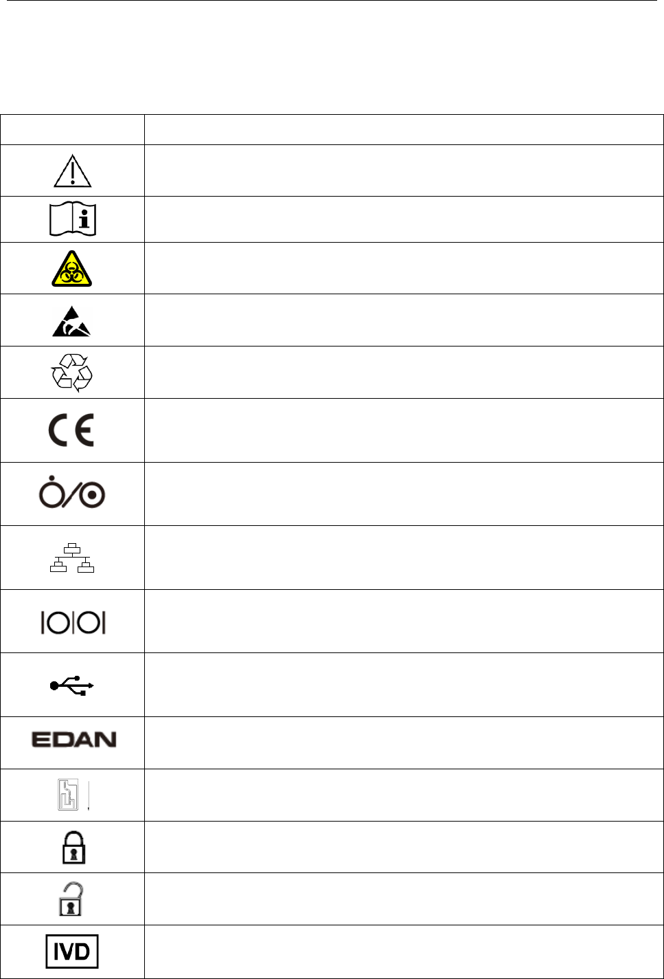
The following symbols will appear on the packaging of the system:
Symbol Description
Caution!
Consult instructions for use
Biological risks
Static electricity sensitive
Recycle
The symbol indicates that the device complies with the European Council
Directive 98/79/EEC concerning medical devices.
On/Off button
Network port
Serial port
USB (Universal Serial Bus) connection
Trademark
Test cartridge insert direction
Calibrant fluid pack chamber door is closed.
Calibrant fluid pack chamber door is open.
In vitro diagnostic device
i15 Blood Gas and Chemistry Analysis System User Manual Safety Guide
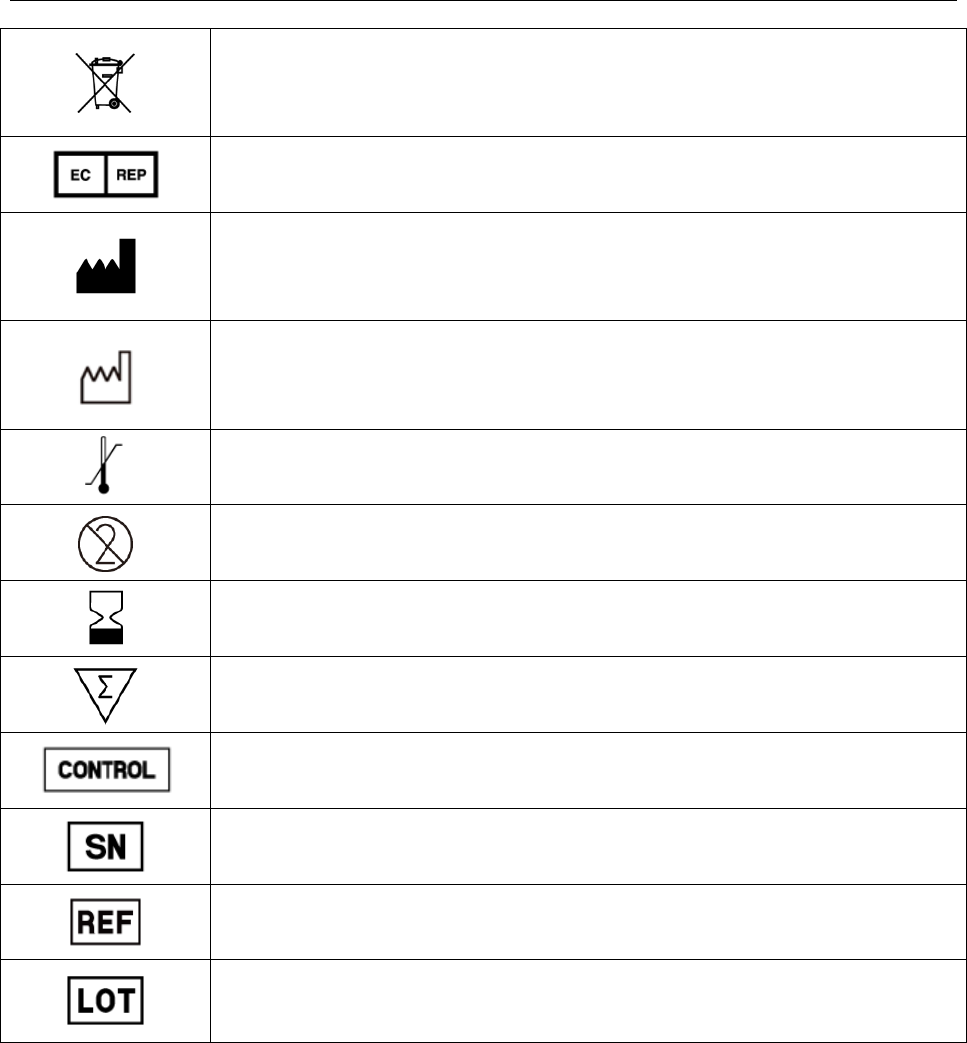
- 7 -
Indicates that the device should be sent to special agencies according to
local regulations for separate collection after its useful life.
Authorized representative in the European Community
Manufacturer
Date of manufacture
Temperature limitations
Do not reuse
Use by
Contains sufficient for (n) tests
Control
Serial number
Catalog number
Batch code

i15 Blood Gas and Chemistry Analysis System User Manual System Overview
- 8 -
Chapter 2 System Overview
NOTE:
The pictures and interfaces in this manual are for reference only.
2.1 Introduction
The system is for in-vitro analysis of whole blood, designed to deliver quantitative results for a
panel of tests. The product consists of an analyzer incorporating a user interface with a large color
touch screen interfacing to the electronic analyzer. The user interface module contains the
analyzer CPU and all of the required electronic interfaces for external communication and data
storage. The product consists of a single-use cartridge into which the sample is introduced. The
cartridge contains electrochemical sensors which generate signals related to concentration levels
in the blood. These concentration levels are displayed on the screen of the analyzer, stored in
memory, and can be transmitted by communication link or Wi-Fi to the Data Management
System (DMS).
The following tables list the parameters that can be determined by the system:
Measured Parameters:
Symbol Description
pH Negative logarithm of the hydrogen ion concentration
pCO2 Partial pressure of carbon dioxide
pO2 Partial pressure of oxygen
K+ Potassium ion concentration
Na+ Sodium ion concentration
Cl- Chloride ion concentration
Ca++ Concentration of ionized calcium
Hct Hematocrit: the volume occupied by red blood cells in a given volume of whole
blood.

i15 Blood Gas and Chemistry Analysis System User Manual System Overview
- 9 -
Calculated Parameters:
Symbol Description
cH+ Hydrogen ion concentration
cH+ (T) Hydrogen ion concentration corrected for entered patient temperature
pH (T) pH value corrected for entered patient temperature
pCO2 (T) pCO2 corrected for entered patient temperature
pO2 (T) pO2 corrected for entered patient temperature
HCO3-act Bicarbonate ion concentration
HCO3-std Bicarbonate ion concentration normalized to a pCO2 of 40mmHg
BB (B) Buffer base
BE (B) Base excess (B)
BE (ecf) Base excess (ecf)
ctCO2 Total carbon dioxide
Ca++ (7.4) The ionized calcium concentration of blood normalized to pH 7.4
AnGap An approximation of the difference between measured cations and measured
anions in the sample
tHb (est) An estimation of the hemoglobin contained in the sample
sO2 (est)
An estimation of hemoglobin oxygen saturation: a ratio of
the amount of
hemoglobin bound to oxygen to the total amount of hemoglobin able to bind
oxygen
pO2 (A-a) Alveolar-arterial oxygen tension difference
pO2 (A-a) (T) Alveolar-arterial oxygen tension difference
corrected for entered patient
temperature
pO2 (a/A) Arterial-alveolar oxygen tension ratio
pO2 (a/A) (T) Arterial-alveolar oxygen tension ratio corrected for entered patient temperature
i15 Blood Gas and Chemistry Analysis System User Manual System Overview
- 10 -
RI Respiratory index: the ratio of the alveolar-arterial blood oxygen-pressure
difference to arterial pO2
RI (T)
Respiratory index: the ratio of the alveolar-arterial blood oxygen-pressure
difference to arterial pO2
when both values are corrected for patient
temperature
pO2/FIO2 The ratio of arterial pO2 to the fraction of inspired oxygen
pO2 (T)/FIO2 The ratio of arterial pO2 to the fraction of inspired oxygen corrected for the
entered patient temperature
Configuration: main unit, printer, scanner, and simulator.
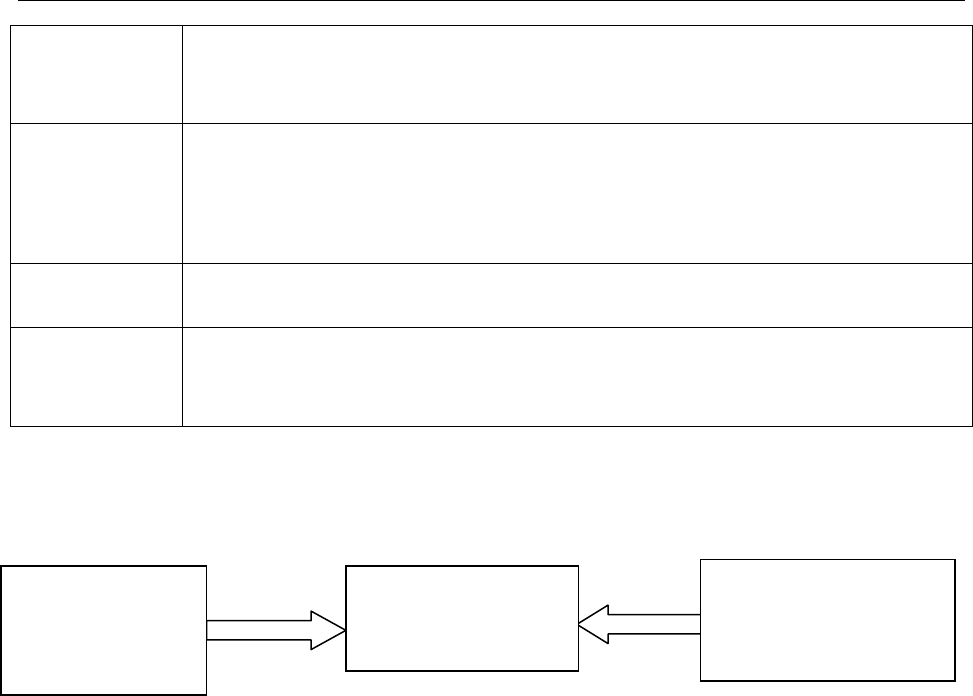
2.2 System Frame
Blood Gas and Chemistry Analyzer
The Blood Gas and Chemistry Analyzer is an electronic instrument which is used to analyze
whole blood samples (measuring blood gases, electrolytes, metabolites, and hematocrit). The
analyzer can:
Scan bar codes of test cartridges, calibrant fluid packs, controls, patient and operator ID,
etc.
Identify the types of test cartridges.
Control the flow of fluids.
Maintain sample temperature at 37°C.
Measure the ambient barometric pressure and ambient temperature.
Measure electrical signals generated by chemical sensors and biosensors.
Analyze and display the concentrations of analytes in whole blood samples.
Transmit test results to the Data Management System (DMS).
Blood Gas and
Chemistry
Analyzer
Data Management
System (DMS)
Laboratory/Hospital
Information System
(LIS/HIS)

i15 Blood Gas and Chemistry Analysis System User Manual System Overview
- 11 -
Store all kinds of test results and data, such as patient sample results, control test results,
proficiency test results, simulator test results, etc.
Animatedly demonstrate the operating process.
Data Management System (DMS)
DMS refers to a computer which is loaded with the data management software. With the
DMS, you can:
Enter test application data.
Edit patient information, view, check and print test results.
View, check and print quality control (QC) test results.
Search for patient test results by patient name, patient ID, date and time, department, etc.
Calculate the amount of work of a physician, the results for a parameter of a patient
during a period, the test times and the fee of a parameter, and print the statistics results.
Set the following items: operator, department, sample status, printing, bar code, etc.
Backup and restore data, view logs.
View data for instrument diagnosis.
Import patient information from LIS/HIS.
Manage up to 20 analyzers simultaneously, storing test results transmitted by analyzers.
NOTE:
Sample ID should be different on analyzers connecting to the same DMS.
HIS/LIS
HIS/LIS transmits patient information to the DMS.
i15 Blood Gas and Chemistry Analysis System User Manual System Overview
- 12 -
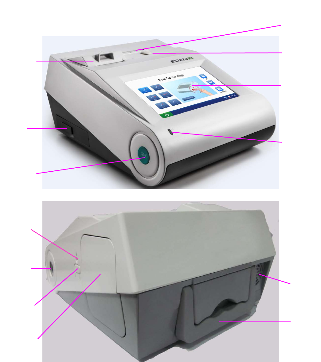
2.3 Analyzer Appearance
Handle
Exhaust
Fan
Calibrant
Fluid Pack
Chamber
Calibrant
Fluid Pack
Ejector
Bar Code
Scanner
Calibrant
Fluid Pack
Chamber
Lock
Thermal
Printer
I/O
Ports
On/Off
Button
Power
Indicator
Test
Cartridge
Port
LCD
Screen
Test
Cartridge
Ejector Cap
i15 Blood Gas and Chemistry Analysis System User Manual System Overview
- 13 -
Figure 2-1 Analyzer Major Components
2.4 System Parts
2.4.1 Thermal Printer
The thermal printer is located at the upper left top of the analyzer. It can print patient sample test
results, quality control test results, calibration results, etc.
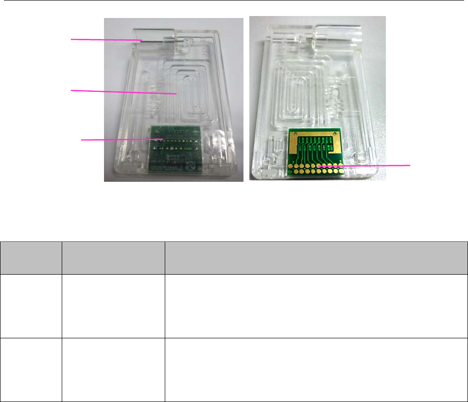
2.4.2 Test Cartridge
Next to the thermal printer is the test cartridge port. A test cartridge is inserted into the analyzer
through the test cartridge port. An indicator is located inside the test cartridge port. If the test
cartridge is inserted properly, the indicator will turn green. If not, the indicator will turn red, and
the system will prompt you. If you want to perform an external electronic simulator test, you also
need to insert the simulator into the test cartridge port.
The unit-use test cartridge is intended to be used together with the analyzer. The fluidic chamber
on the test cartridge is used to hold used calibrants and sample fluids. The sensors on the test
cartridge can generate electrical signals that can be measured by the analyzer. The sample fillport
is used to connect the syringe/capillary tube for automatically aspirating samples. Test cartridges
are available in different configurations concerning the type of parameters reported by them. For
details, please refer to the table below.
Battery
Compartment
i15 Blood Gas and Chemistry Analysis System User Manual System Overview
- 14 -
Figure 2-2 Test Cartridge
Table 2-1 Test Cartridge Types
Cartridge
Type
Measured
Parameters Calculated Parameters
BG8
pH, pCO2, pO2,
Na+, K+, Cl-, Ca++,
Hct
cH
+
, HCO3
-
act, HCO3
-
std, BE (ecf), BE (B), BB (B), ctCO2,
sO2 (est), Ca++ (7.4), AnGap, tHb (est), pO2 (A-a), pO2 (a/A),
RI, pO2/FIO2, cH+ (T), pH (T), pCO2 (T), pO2 (T),
pO2 (A-a) (T), pO2 (a/A) (T), RI (T), pO2 (T)/FIO2
BG3 pH, pCO2, pO2
cH
+
, HCO3
-
act, HCO3
-
std, BE (ecf), BE (B), BB (B), ctCO2,
sO2 (est), pO2 (A-a), pO2 (a/A), RI, pO2/FIO2, cH+ (T), pH (T),
pCO2 (T), pO2 (T), pO2 (A-a) (T), pO2 (a/A) (T), RI (T),
pO2 (T)/FIO2
Packaging
1. The type of the cartridge is labeled on the test cartridge.
2. Each test cartridge is sealed in a foil pouch containing a strip of desiccant.
3. The bar code on the foil pouch contains information such as the cartridge type, lot number
and expiration date, etc.
4. 25 test cartridges are packaged per box, and 4 boxes are packaged into a shipping carton.
Storage and Usage
Test cartridges should be stored at 4 - 30°C, and should be used at 10 - 31°C with the relative
humidity of 25% - 80% (non-condensing).
Sensor
Arrays
Fluidic
Chamber
Fillport
Electrical
Contacts

i15 Blood Gas and Chemistry Analysis System User Manual System Overview
- 15 -
Disposal
The sample is contained in the test cartridge, so test cartridges should be disposed of as
biohazardous waste, complying with local regulatory guidelines.
NOTE:
If the pouch has been damaged, the test cartridge should not be used.
Only test cartridges provided by EDAN or its authorized distributors should be used.
Only test cartridges properly stored should be used.
Never reuse test cartridges.
Never touch the fillport or electrical contacts of a test cartridge.
Use test cartridges before their expiration date as labeled on the package, and use
them immediately after removing them from their pouches.
Test cartridges should be kept out of direct sunlight and heat.
The analyzer, test cartridges and the testing environment should be at the same
temperature prior to a test.
Test cartridges should not be dropped or stressed.
2.4.3 Power Indicator
The power indicator is on the lower left bottom of the analyzer. During the operation you can see
one of the following:
Green Light: The analyzer is on and the power supply is normal. The analyzer can be
powered either by the rechargeable lithium battery or AC power. Or the system is off and has
been connected to AC power.
Blinking Yellow Light: The power is supplied by the rechargeable lithium battery and the
battery is low.
Yellow Light: The rechargeable lithium battery is being charged.
2.4.4 LCD Screen and Touch Screen
The activities of the analyzer are communicated to you through the LCD screen, displaying the
analyzer activities, test results, database information, prompts, etc. You communicate with the
analyzer through the touch screen which allows you to perform tests, make selections, enter data,
and view information, etc.
i15 Blood Gas and Chemistry Analysis System User Manual System Overview
- 16 -
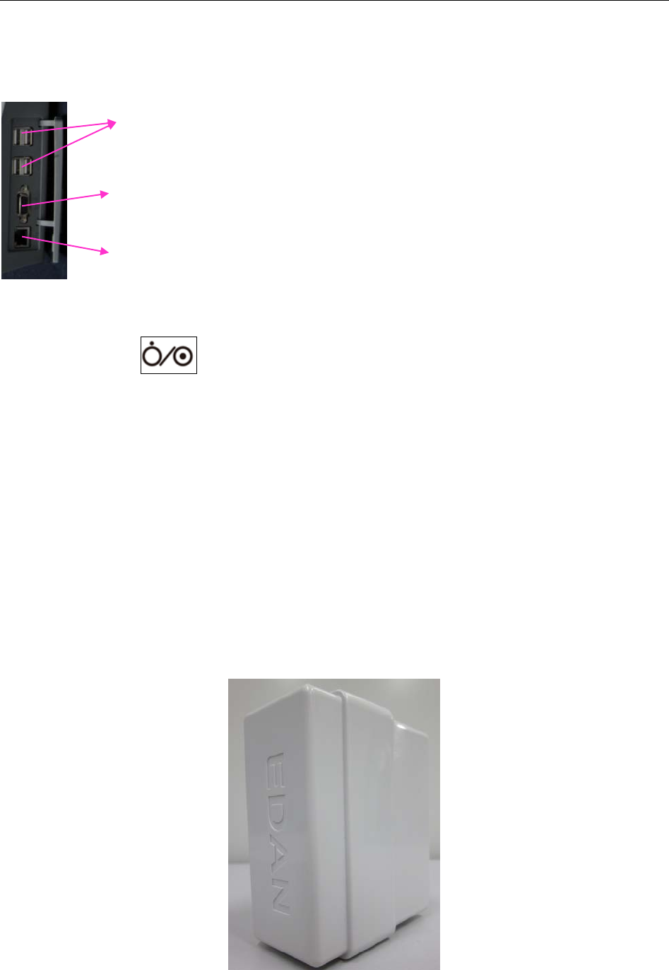
2.4.5 I/O Ports
On the left side of the analyzer are I/O ports:
2.4.6 On/Off Button
The On/Off button is on the left side of the analyzer.
2.4.7 Calibrant Fluid Pack
The calibrant fluid pack chamber is on the right side of the analyzer. You can install the calibrant
fluid pack in it for sensor calibration. The calibrant fluid pack ejector beside the door is used to
open the chamber door. On the calibrant fluid pack ejector is a calibrant fluid pack chamber lock
to help users close the calibrant fluid chamber door securely.
A calibrant fluid pack containing calibrant solutions is intended to be used together with the
analyzer to perform one-point sensor calibration. Calibrant fluid packs are available for 100 and
200 sampling operations. Contact EDAN or its authorized distributors to order calibrant fluid
packs for your system.
Figure 2-3 Calibrant Fluid Pack
USB Interfaces (4): allow you to connect your analyzer with peripherics such
as scanners, printers, etc.
Serial Port: allows engineers from the factory to perform debugging.
Network Port: allows network connection to the DMS.

i15 Blood Gas and Chemistry Analysis System User Manual System Overview
- 17 -
Packaging
1. The calibrant fluid pack is sealed in a foil pouch filled with protective gases.
2. The bar code on the foil pouch contains information such as the lot number and expiration
date.
3. Each calibrant fluid pack is packaged into a box, and 6 boxes are packaged into a shipping
carton.
Storage and Usage
Calibrant fluid packs should be stored at 2 - 8°C (avoid freezing) with the ambient pressure of 65
- 106.6kPa, and should be used at 10 - 31°C with the relative humidity of 25% - 80%
(non-condensing). The calibrant fluid pack expires 30 days after its installation or after exceeding
the labeled expiration date, whichever comes first. The remaining days and usages are displayed
on the status bar at the bottom of the screen.
NOTE:
If the pouch has been damaged or there is any leakage, the calibrant fluid pack
should not be used.
Only those calibrant fluid packs provided by EDAN or its authorized distributors
should be used.
Use calibrant fluid packs before their expiration date as labeled on the package.
A calibrant fluid pack is intended for single use only. If a calibrant fluid pack is
removed from the system, it cannot be inserted into the system again.
2.4.8 Bar Code Scanner
On the same side as the calibrant fluid pack chamber is the built-in scanner for scanning bar
codes on test cartridges, calibrant fluid packs, controls, operator ID, patient ID, sample ID, etc.
The analyzer can also be connected to external scanners as mentioned in 2.4.11.
Follow the steps below to scan a bar code:
1. Press Scan Barcode or to activate the bar code scanner, and the scanner will emit a red
beam.
2. Align the bar code with the red beam so that the red beam covers the whole bar code.

i15 Blood Gas and Chemistry Analysis System User Manual System Overview
- 18 -
NOTE:
The distance between the analyzer and the bar code should be 6 - 15cm.
3. If the bar code is scanned successfully, the analyzer will beep and automatically turn off the
scanner.
4. If the scanned data is valid, the system will display the screen for the next procedure. If the
scanned data is invalid, a message will pop up to prompt you.
CAUTION
1. In order to avoid injury, never look into the red beam.
2. To avoid damage, never scratch the protective glasses of the scanner with hard
objects.
3. To avoid damage and injury, never strike the protective glasses of the scanner.
4. To avoid unsuccessful scanning, clean the scanner with a lint-free cloth when there is
visible dirt.
2.4.9 Exhaust Fan
The exhaust fan is located at the rear of the analyzer to prevent the analyzer from overheating.
When the analyzer temperature is over preset threshold, the fan will be automatically turned on.
NOTE:
Make sure that the vents of the analyzer are not obstructed to ensure good
ventilation.
If the exhaust fan does not run properly, please contact EDAN or its authorized
distributors for assistance.
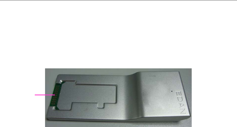
2.4.10 Electronic Simulator
Electronic simulators are quality control devices for checking the analyzer’s ability to take
accurate measurements of voltage, current and conductivity from test cartridges.
Internal Electronic Simulator
Internal electronic simulator is self-contained in the analyzer for automatically conducting
simulator tests at the preset frequency.
i15 Blood Gas and Chemistry Analysis System User Manual System Overview
- 19 -
External Electronic Simulator
Users can run the external electronic simulator test according to their own needs, and EDAN
recommends that users run it every 24 hours. Each external electronic simulator is packaged
separately. When you have doubt about the reliability of test results, you can run the external
electronic simulator test to help troubleshoot.
Figure 2-4 External Electronic Simulator
If the contact pads have been contaminated, please clean the external electronic simulator.
Follow the steps below to clean the external electronic simulator:
1. Moisten a lint-free cloth with 100% alcohol;
2. Wipe the external electronic simulator with the lint-free cloth.
NOTE:
Never immerse the simulator into any liquids.
The cloth should be wet but not dripping.
2.4.11 Peripherics
Only the following external scanners should be connected to the analyzer through USB ports:
Honeywell 1900.
Only the following external printers should be connected to the analyzer through USB ports: HP
LaserJet P401DN, and HP LaserJet P1606DN.
NOTE:
Only peripherics recommended by EDAN should be connected to the analyzer.
When connecting a Honeywell 1900 scanner to the analyzer, the scanner should be
set.
Contact pads

i15 Blood Gas and Chemistry Analysis System User Manual System Overview
- 20 -
2.5 Configuration
2.5.1 Standard Configuration
i15 analyzer
1 power cable
1 power adaptor
4 printer paper
1 rechargeable lithium battery
1 user manual
1 warranty card
2 packing lists
2.5.2 Options
Test cartridges
Calibrant fluid pack
External electronic simulator
Capillary adaptor
Controls
Data management system software
Honeywell 1900 scanner

i15 Blood Gas and Chemistry Analysis System User Manual Installation Guide
- 21 -
Chapter 3 Installation Guide
3.1 Unpacking Inspection
Visually examine the package prior to unpacking. If there are any signs of mishandling or damage,
contact the carrier to claim for damage. After unpacking the device, customers should follow the
PACKING LIST to check the product carefully and to make sure no damage occurred during
transportation. Then, install the device according to the installation requirements and procedures.
If there is any problem, contact the manufacturer or its authorized distributors immediately.
WARNING
DO NOT use the analyzer if it is damaged or defective.
NOTE:
Keep the package for future transportation or for storage.
3.2 Installation Requirements
3.2.1 Environmental Requirements
Location is of great importance for the smooth running of your analyzer. Prior to installing the
analyzer, choose a site that meets the following requirements:
Convenient for the analyzer to be connected to a grounded electrical receptacle in case it is
powered by AC power.
Keep the analyzer away from direct exposure to strong sunlight.
Ambient Temperature between 10°C and 31°C.
Relative Humidity of 25% - 80% (non-condensing).
Ambient Pressure within 70 - 106.6kP (525 - 800mmHg).
Placed onto a clean and flat surface with good ventilation.
Keep the analyzer away from equipment with strong electric field and strong magnetic field.
Keep the analyzer away from explosive gases or vapors.
NOTE:
The requirements above also apply when your analyzer is powered by a rechargeable
lithium battery.

i15 Blood Gas and Chemistry Analysis System User Manual Installation Guide
- 22 -
3.2.2 Power Requirements
The analyzer needs to be connected to a grounded electrical outlet with the voltage between
100±10% VAC - 240±10% VAC and the frequency of 50/60Hz.
3.3 Setting Up
Now you can prepare your analyzer for operation.
First, please place the analyzer on a secure table surface with environments that meet the
requirements as described in section 3.2.
3.3.1 Connecting to AC Power
1. Insert the power adaptor into the power connector on the analyzer.
2. Plug the power cord into the power adaptor.
3. Plug the power cord into a grounded electrical outlet.
NOTE:
Make sure the power requirements as described in 3.2.2 are met.
To avoid the analyzer and other electronic devices being damaged by electrical power
spikes, a surge protector is recommended.
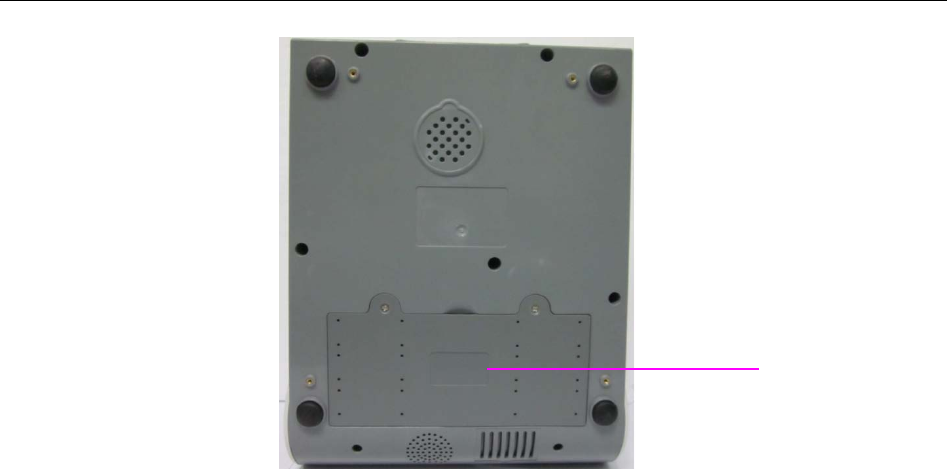
3.3.2 Installing the Battery
Switch off the analyzer and unplug it before installing or removing the battery.
WARNING
If the analyzer is powered by a rechargeable lithium battery, please install the battery first.
Battery Installation
Follow the steps below to install the battery:
1. Turn off the analyzer, disconnect the power supply, and remove the power adaptor and other
connecting cables.
2. Place the analyzer upside down on a flat surface covered with cloth or another type of
protecting pad.
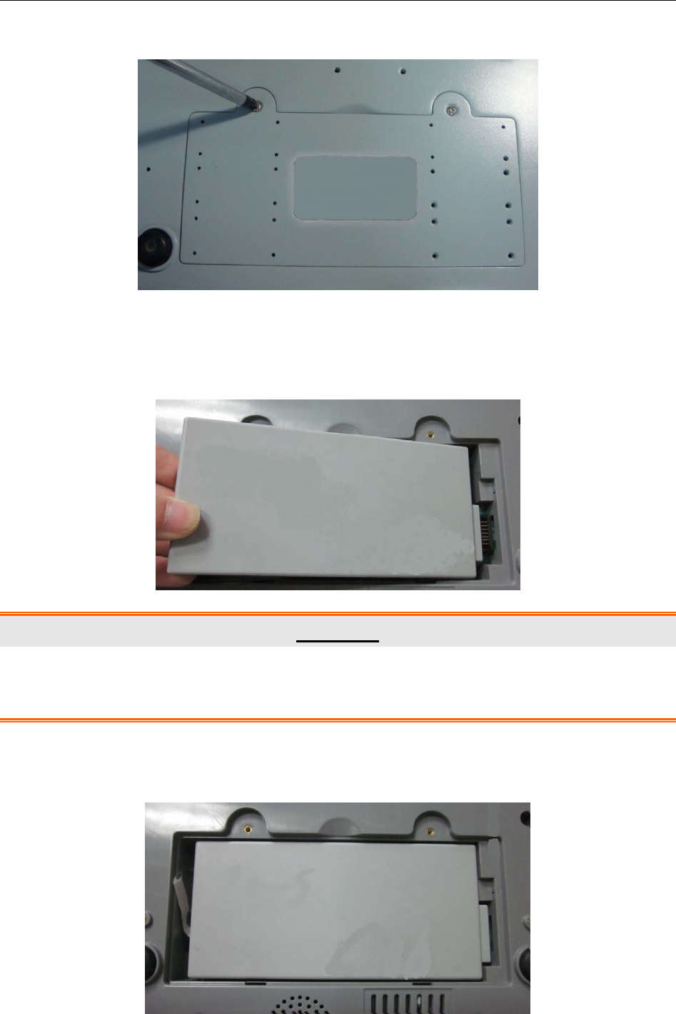
3. Remove the screws of the battery compartment using a cross-head screw driver, and then
i15 Blood Gas and Chemistry Analysis System User Manual Installation Guide
- 23 -
remove the battery compartment cover.
4. Take the battery out from its package and put it into the compartment. Make sure the battery
connector is on the right and the battery label faces down. Install the battery into the
compartment.
WARNING
Do not touch the battery connector with fingers or metallic materials, to avoid the hazards
posed by the short-circuit to you and the battery.
5. Arrange the battery flat in the compartment, and push the strip at the end of the battery into
the gap.

i15 Blood Gas and Chemistry Analysis System User Manual Installation Guide
- 24 -
6. Shut the battery compartment cover and secure it with the screws.
Battery Removal
Remove the battery in reverse order. You can pull the strip at the end to take the battery out from
the compartment.
NOTE:
The battery needs to be charged prior to using it.
Only those batteries supplied by EDAN or its authorized distributors should be used
with the analyzer.
When the analyzer is powered by the battery and the battery is low, the system will
prompt you to connect the analyzer to an external power outlet. At the same time, the
battery indicator icon on the status bar at the bottom of the screen will also blink.
The battery will automatically be charged whenever the analyzer is connected to an
electrical outlet.
3.3.3 Installing the Printer Paper
The analyzer utilizes rolled thermal paper with the width of 50mm. When the printer paper runs
out during the printing or is not loaded, the warning message “Paper?” will appear on the screen.
Then you should load or replace the printer paper immediately.
Procedures for Loading Rolled Thermal Paper
1. Open the casing.
2. Gently place the paper in the paper tray with the outside of the paper facing the thermal print
head.
3. Pull about 2 cm of paper out and shut the printer casing.
i15 Blood Gas and Chemistry Analysis System User Manual Installation Guide
- 25 -
Procedures for Replacing Rolled Thermal Paper
The procedures for replacing rolled thermal paper is almost the same as loading rolled thermal
paper, except that you need to remove the remained rolled thermal paper prior to step 2.
CAUTION
1. Only use the printer paper provided by EDAN or its authorized distributors, otherwise
the printer may be damaged. This kind of damage is not covered by warranty.
2. Do not touch the thermosensitive print head or the paper sensor by hand, in case
they are damaged by static electricity.
NOTE:
Unless when replacing paper or troubleshooting, do not leave the printer casing open.
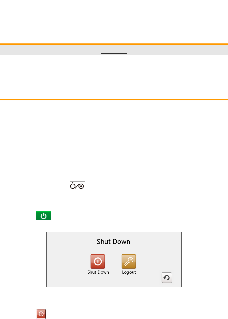
3.3.4 Turning On/Off the Analyzer
NOTE:
Make sure that all the cables are securely connected before you turn on the analyzer.
Turn On the Analyzer
Press the On/Off button on the left side of the analyzer to turn it on.
Turn Off the Analyzer
1. Press on the bottom left of the screen, the following message will pop up:
Figure 3-1 Turn Off Analyzer
2. Press , and press OK in the pop up dialog box.
NOTE:
Never turn off the system when it is performing tests or printing data.
i15 Blood Gas and Chemistry Analysis System User Manual Installation Guide
- 26 -
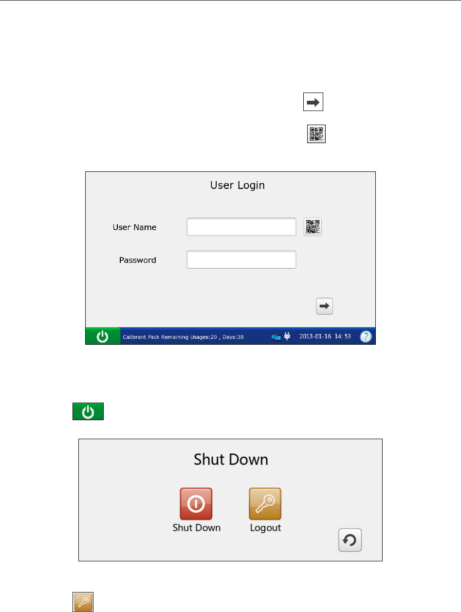
3.3.5 User Login and Logout
User Login
1. Press the On/Off button on the left hand side of the analyzer to turn it on.
2. Enter the user name and password manually, and press .
To enter the user name with the bar code scanner, press first, and then scan the user
name bar code.
Figure 3-2 Enter User Name and Password
User Logout
1. Press on the bottom left of the screen, the following message will pop up:
Figure 3-3 User Logout
2. Press , and press OK in the pop up dialog box. The system will go to the User
Login screen. Enter a user name and password to change users.
NOTE:
Never log out of the system when it is performing tests or printing data.

i15 Blood Gas and Chemistry Analysis System User Manual Installation Guide
- 27 -
3.3.6 Setting the Date and Time
1. On the Main screen, press to access the System Setup screen.
2. Press to access the Date & Language Setup screen.
3. Select the desired date and time, and press OK in the pop up dialogue box.
4. Press OK to accept the changes.
5. Press Return to return to the Main screen.
CAUTION
1. Make sure the current date and time of the system are correct, or it may cause
misdiagnosis.
2. Changing date and time directly affects date and time saved with each test data.
3.4.7 Viewing Training Videos
The system has training videos for guiding your operations.
Follow the steps below to view training videos:
1. Press on the bottom right of the screen to access the Help screen.
Figure 3-4 Help Screen
2. Press to view the video for replacing a calibrant fluid pack.
3. Press to view the video for analyzing syringe samples.
4. Press to view the video for analyzing ampoule samples.
i15 Blood Gas and Chemistry Analysis System User Manual Installation Guide
- 28 -
5. Press to view the video for analyzing capillary samples.
6. Press Return to go back to the Main screen.
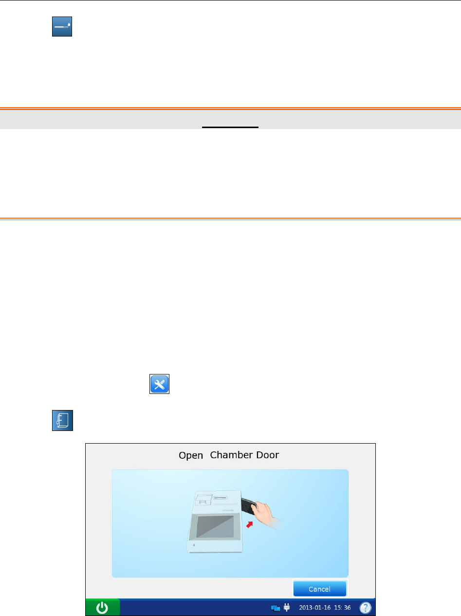
3.4.8 Replacing a Calibrant Fluid Pack
WARNING
1. The replacement of a calibrant fluid pack should be performed only when the
analyzer is on.
2. A calibrant fluid pack is intended for single use only. If a calibrant fluid pack is
removed from the system, it can not be inserted into the system again.
Follow the steps below to replace a calibrant fluid pack:
1. Examine the expiration date on the package of a calibrant fluid pack to ensure it has not
expired.
2. Remove the calibrant fluid pack from its package, and equilibrate it to room temperature.
The calibrant fluid pack needs to stand at room temperature for at least 24 hours.
3. Wipe any moisture from the foil pouch with a dry clean cloth.
4. On the Main screen, press to go to the System Setup screen.
5. Press . The system will go to the screen below:
Figure 3-5 Open Chamber Door
6. Open the foil pouch, and remove the calibrant fluid pack from it.
i15 Blood Gas and Chemistry Analysis System User Manual Installation Guide
- 29 -
NOTE:
Avoid tearing the bar code on the foil pouch.
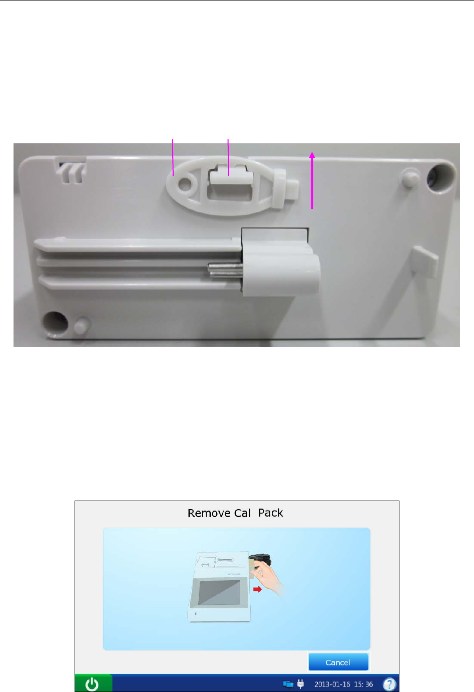
7. Remove the calibrant fluid pack cap, and remove the key by pushing it with your finger in
the direction as shown by the arrow in the picture below.
NOTE:
Avoid pushing the valve when removing the key.
8. Unlock the calibrant fluid pack chamber lock with the key, and then pull the calibrant fluid
pack ejector to open the calibrant fluid pack chamber door.
9. Remove the used calibrant fluid pack from the system. The system will go to the screen for
the next procedure, and the scanner will be turned on automatically.
Figure 3-6 Remove Old Calibrant Fluid Pack
Valve
Key
i15 Blood Gas and Chemistry Analysis System User Manual Installation Guide
- 30 -
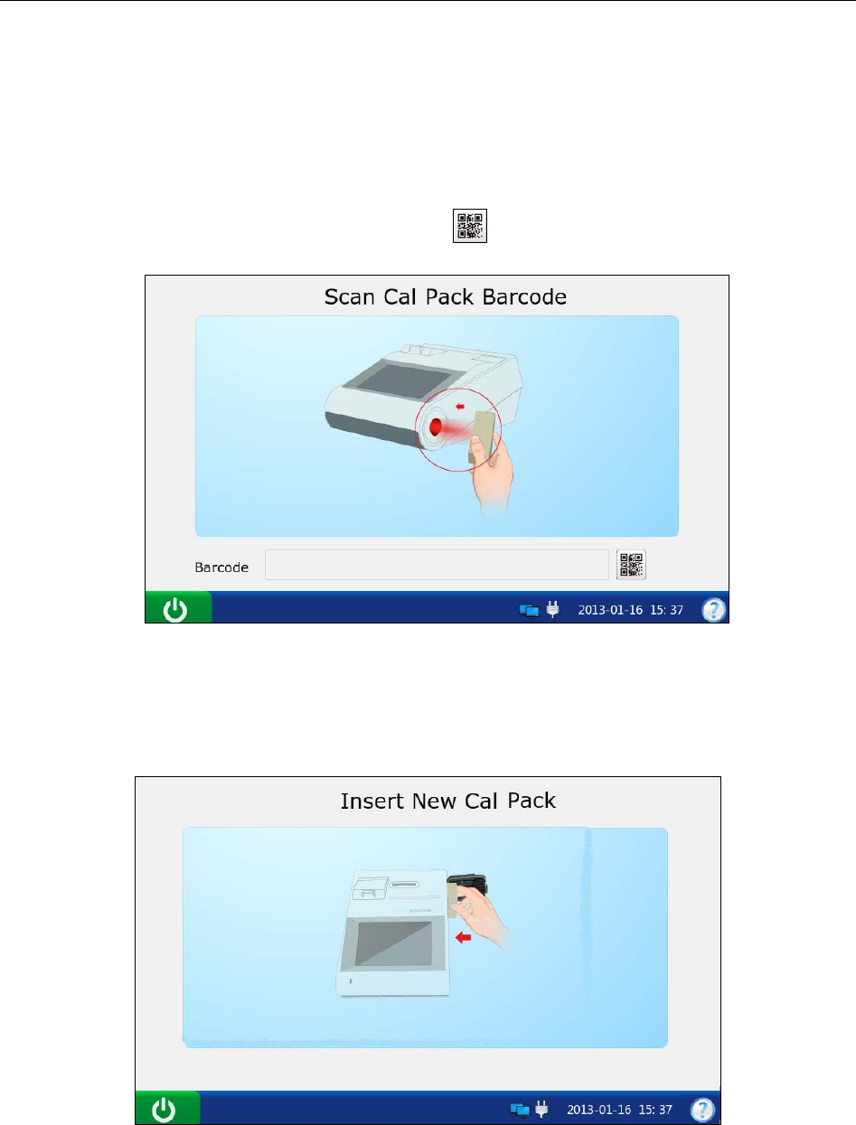
10. Scan the bar code on the new calibrant fluid pack foil pouch with the bar code scanner.
If the bar code is scanned successfully, the system will beep and the scanner will be turned off
automatically. If the scanned data is valid, the system will display the screen for the next
procedure. If the scanned data is invalid, a message will pop up to prompt you.
If the scanner is turned off automatically, press first, and then scan the bar code.
Figure 3-7 Scan Bar Code
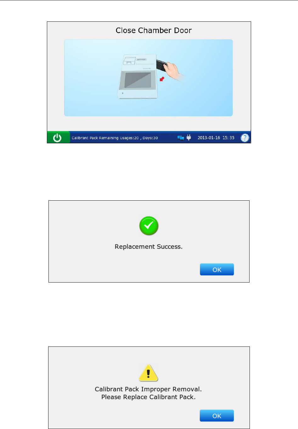
11. Insert the new calibrant fluid pack into its chamber, and push it gently to make sure that it
clicks into place. The system will go to the screen for the next procedure.
Figure 3-8 Install Calibrant Fluid Pack
i15 Blood Gas and Chemistry Analysis System User Manual Installation Guide
- 31 -
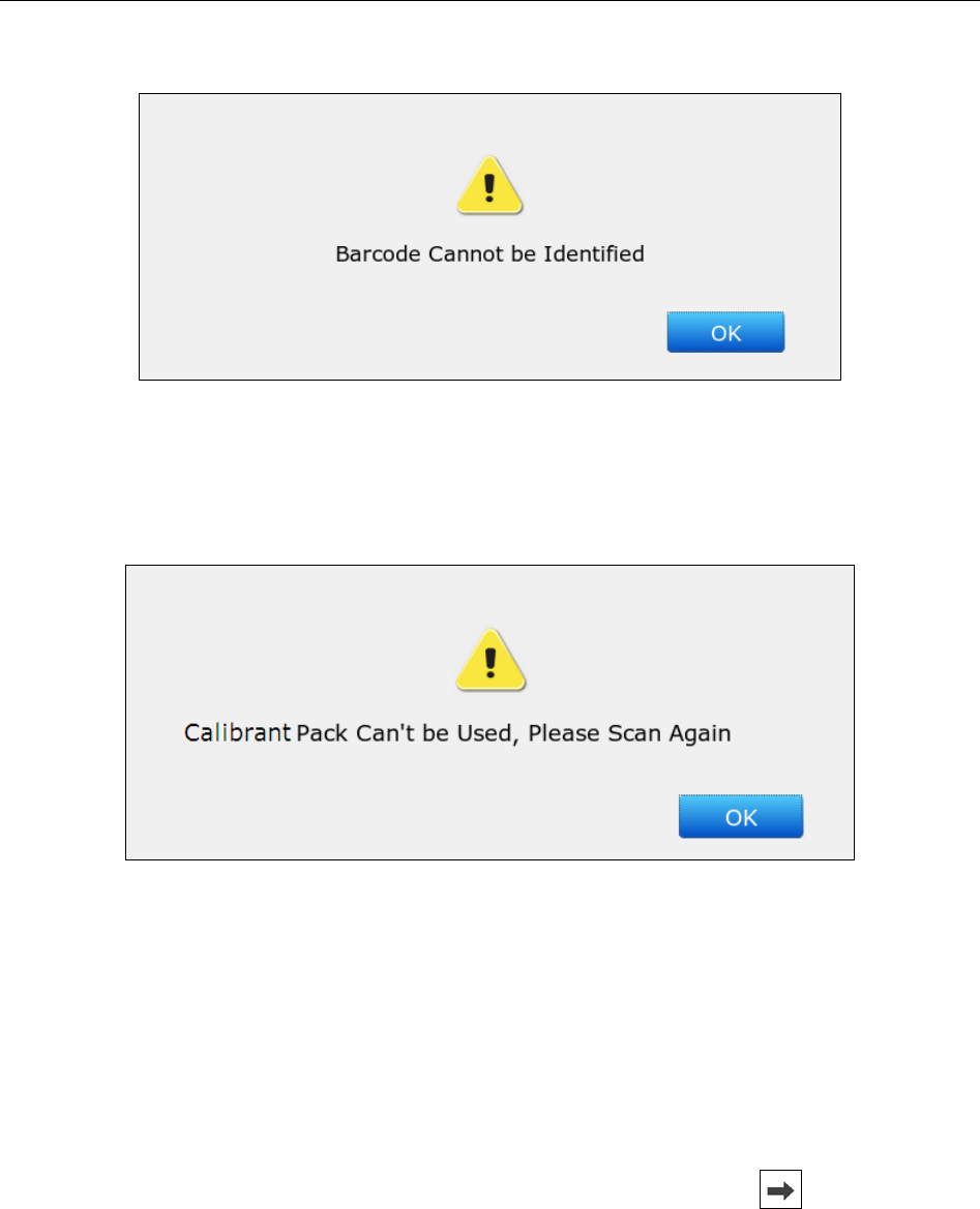
12. Close the chamber door.
Figure 3-9 Close Chamber Door
13. Lock the calibrant fluid pack chamber lock to close the chamber door securely.
14. Press OK in the pop up message. The system will then go to the Main screen.
Figure 3-10 Replacement Success
NOTE:
Always follow the proper procedures to replace a calibrant fluid pack, or else the
system will not run smoothly, and the following message will pop up:
Figure 3-11 Calibrant Fluid Pack Improper Removal
i15 Blood Gas and Chemistry Analysis System User Manual Installation Guide
- 32 -
If the bar code is not that of a calibrant fluid pack, the following message will pop up:
Figure 3-12 Unidentified Bar Code
If the bar code is that of a used calibrant fluid pack or that of an expired calibrant fluid
pack, the following message will pop up:
Figure 3-13 Calibrant Fluid Pack Can Not be Used
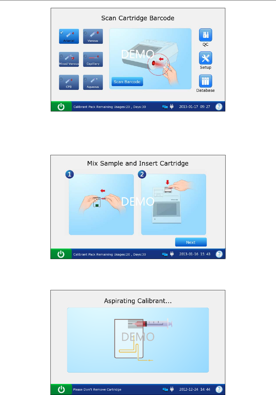
3.3.9 DEMO Test
The system can demonstrate the sample testing processes through animation. Follow the steps
below to perform a DEMO test:
1. Logout of the system. The system will access the User Login screen.
2. Enter demo in both the user name and password fields, and then press . The system will
go to the following screen:
i15 Blood Gas and Chemistry Analysis System User Manual Installation Guide
- 33 -
Figure 3-14 DEMO Test Screen 1
3. Press Scan Barcode.
4. Press Next.
Figure 3-15 DEMO Test Screen 2
5. The system simulates aspirating calibrant.
Figure 3-16 DEMO Test Screen 3
i15 Blood Gas and Chemistry Analysis System User Manual Installation Guide
- 34 -
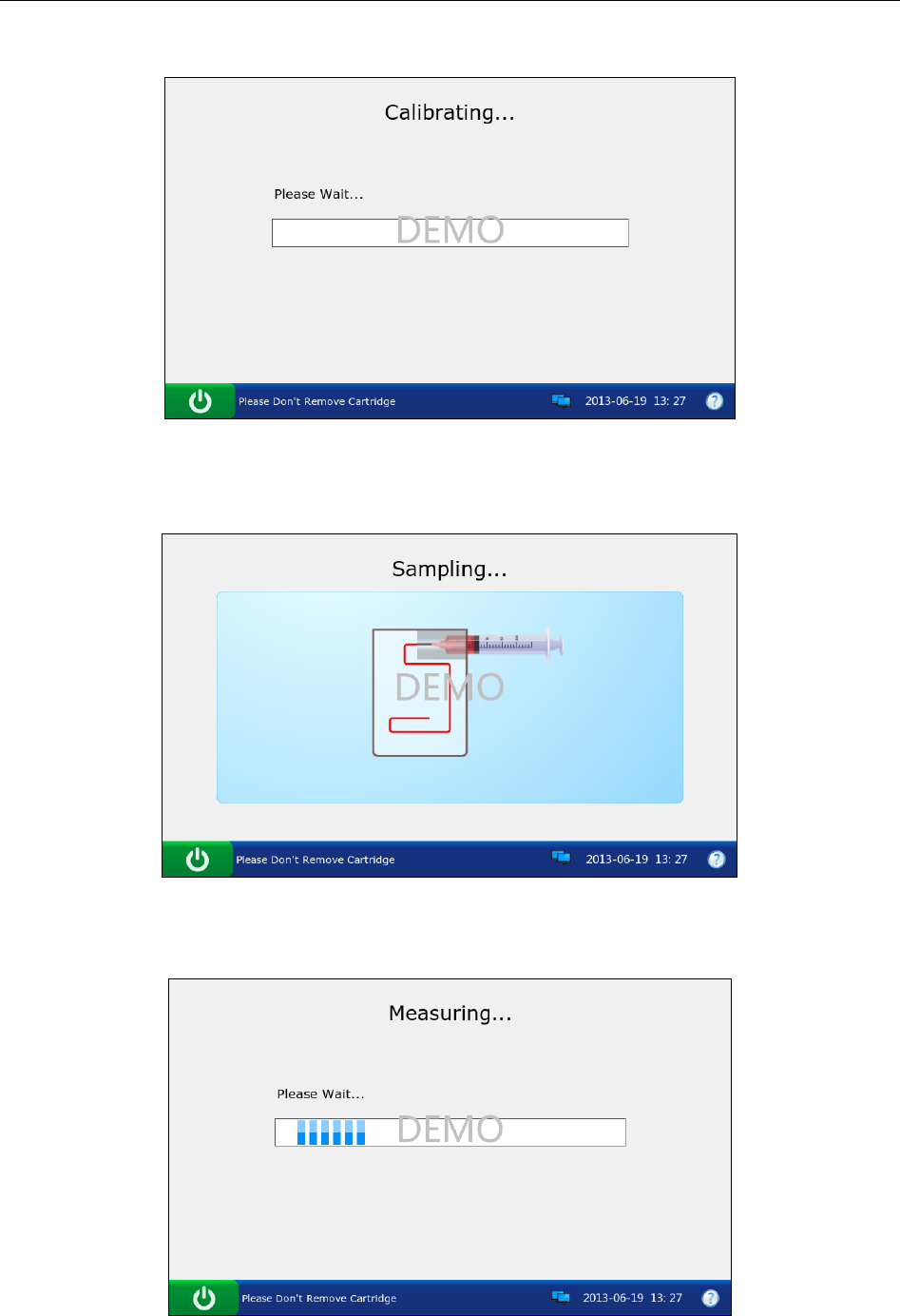
6. The system simulates calibration.
Figure 3-17 DEMO Test Screen 4
7. The system simulates sampling.
Figure 3-18 DEMO Test Screen 5
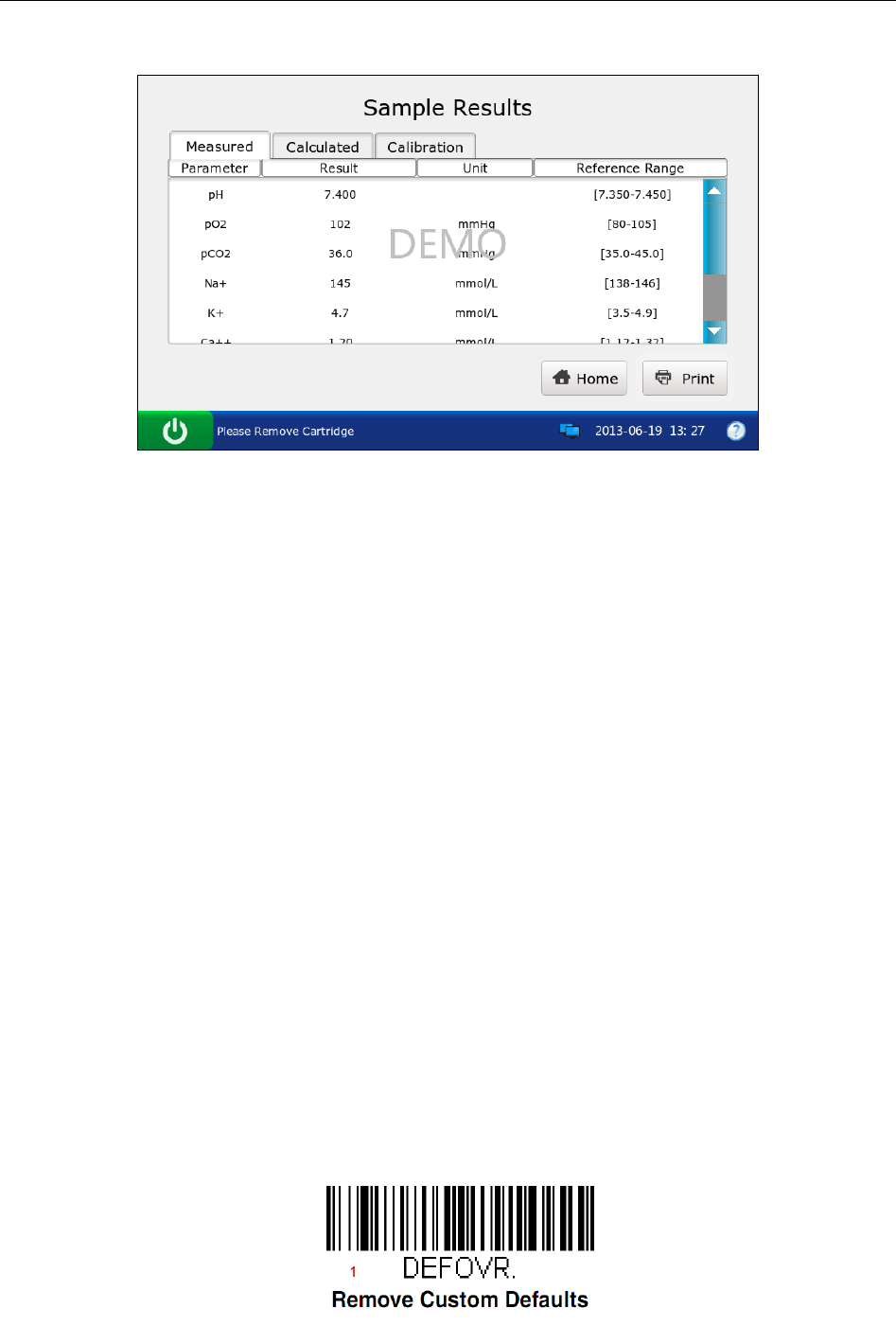
8. The system simulates testing.
Figure 3-19 DEMO Test Screen 6
i15 Blood Gas and Chemistry Analysis System User Manual Installation Guide
- 35 -
9. The system simulates displaying test results.
Figure 3-20 DEMO Test Screen 7
10. Press Home to return.
11. Follow the steps as described in 3.3.5 to logout of the system.
3.3.10 Connecting Peripherics
Connect peripherics with the system through USB ports, and make sure that the system meets the
requirements in IEC60601-1-1.
NOTE:
Only peripherics recommended by EDAN should be connected.
Make sure that the whole system meets the requirements in IEC60601-1-1.
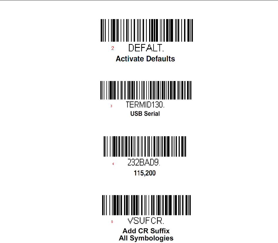
Follow the steps below to set a Honeywell 1900 scanner:
1. Connect a Honeywell 1900 scanner to the analyzer through a USB port.
2. Hold the scanner with your right hand, and trigger the scanner with your forefinger.
3. Scan the following bar codes in sequence.
i15 Blood Gas and Chemistry Analysis System User Manual Installation Guide
- 36 -
4. Use the scanner to scan a bar code of a test cartridge. If the bar code is successfully scanned,
the scanner is successfully set.

i15 Blood Gas and Chemistry Analysis System User Manual Setup
- 37 -
Chapter 4 Setup
The system can be configured according to your clinical needs. The setup can only be done by
authorized operators. You can perform the following setup with the Setup menu:
Printer Setup
Network Setup
Date & Language Setup
Backlight & Volume Setup
QC Lockout Setup
Patient Information Setup
Reference Ranges Setup
Units Setup
Correlation Factors Setup
Hct Setup
NOTE:
Only administrators, service engineers and engineers from the manufacturer can get
access to this function.
The system will remember all the changes in setup even after the system is turned
off.
4.1 Getting into the Setup Screen
1. Press the On/Off button on the left hand side of the analyzer to turn it on.
2. Enter the user name and password manually, and press .
To enter the user name with the bar code scanner, press first, and then scan the user
name bar code.
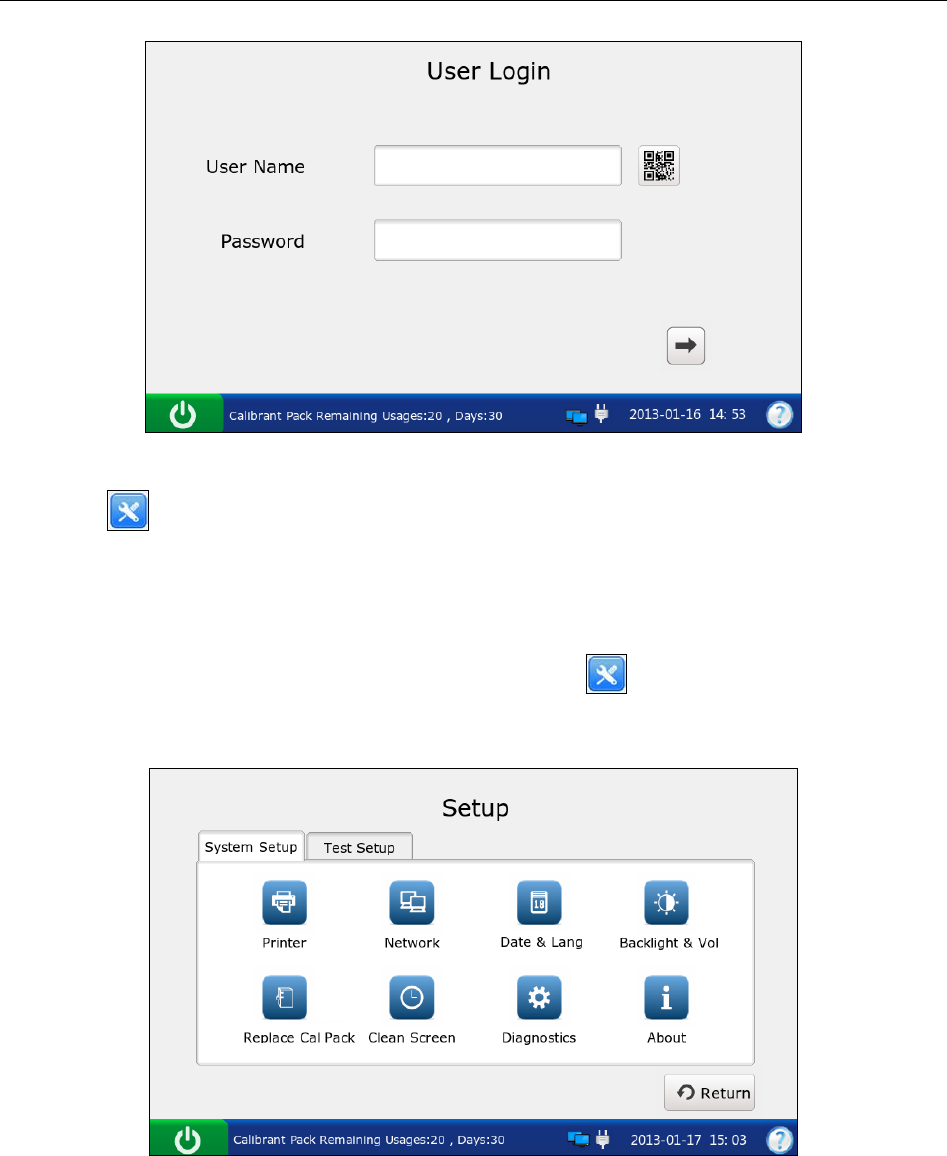
i15 Blood Gas and Chemistry Analysis System User Manual Setup
- 38 -
Figure 4-1 Enter User Name and Password
3. Press on the Main screen, and the system will go to the Setup screen.
4.2 System Setup
The system displays the System Setup screen after pressing on the Main screen by default.
If you are now on the Test Setup screen, press System Setup to get to the System Setup screen.
Figure 4-2 Setup-System Setup Screen
You can perform the following actions:
i15 Blood Gas and Chemistry Analysis System User Manual Setup
- 39 -
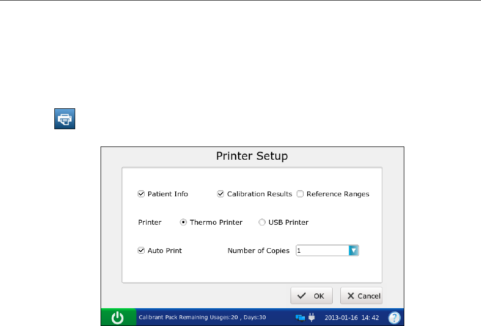
4.2.1 Printer Setup
This menu lets you configure the printer that the system uses, what are printed in reports, and the
number of copies it prints.
Follow the steps below to set the printer:
1. Press to access the Printer Setup screen.
Figure 4-3 Printer Setup Screen
2. On the Printer Setup screen, you can:
Select whether to print patient information. The mark √ will appear if Patient Info is
selected, and the default is to print patient information.
Select whether to print calibration results. The mark √ will appear if Calibration Results is
selected, and the default is to print them.
Select whether to print reference ranges. The mark √ will appear if Reference Ranges is
selected, and the default is to not print them. If Reference Ranges is selected, the reference
ranges will be contained in the patient sample report, and the acceptable ranges will be
contained in the control test report.
Select the printer to be used. There are two options: Thermo Printer and USB Printer. The
default is Thermo Printer.
Select whether to turn on Auto Print. The mark √ will appear if Auto Print is turned on, and
the default is to turn on Auto Print.
Select the number of copies. There are two options: 1 and 2. The default is 1.
3. Press OK to accept the changes, and the system will return to the System Setup screen.
i15 Blood Gas and Chemistry Analysis System User Manual Setup
- 40 -
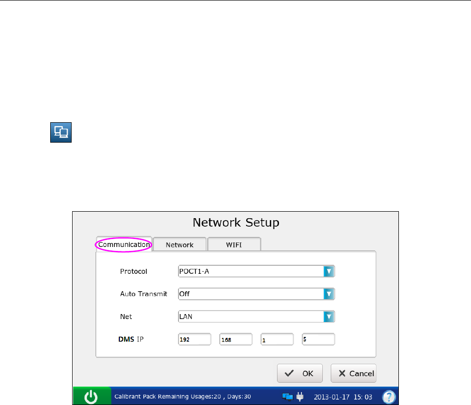
4.2.2 Network Setup
This menu allows you to configure the communication methods, transmitting methods, and the
manner that the analyzer is connected to the network.
Follow the directions below to configure the network:
1. Press to access the Network Setup screen.
2. There are three tabs: Communication, Network, and WIFI.
Network Setup
1) Press Communication to go to the Communication Setup screen.
Figure 4-4 Network – Communication Setup Screen
2) On the Communication Setup screen, you can:
Select the communication protocols. There is only one option: POCT 1-A.
Select whether to transmit patient sample results automatically. There are two
options: On and Off. If your selection is On, patient sample results will be
transmitted automatically after each measurement. The default is On.
Select the communication methods. There are two options: Network and WIFI.
The default is Network.
Enter the IP address of the DMS to which your analyzer is connected.
3) Press OK to accept the changes, and the system will return to the System Setup
screen.
i15 Blood Gas and Chemistry Analysis System User Manual Setup
- 41 -
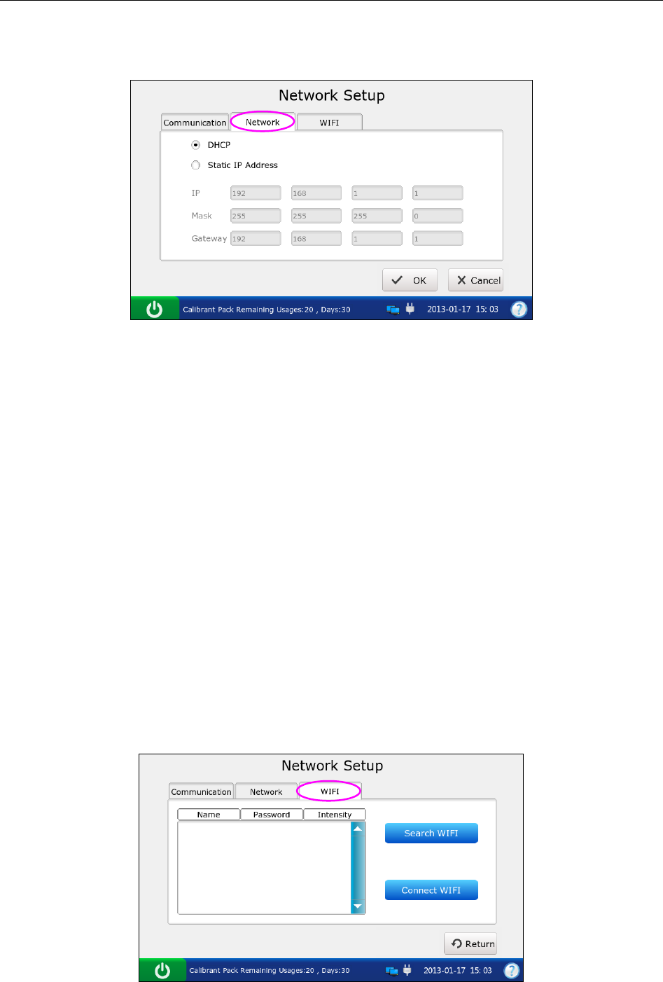
Network Setup
1) Press Network to access the Network-Network Setup screen.
Figure 4-5 Network – Network Setup Screen
2) Select the way that the analyzer is connected to the network. There are two options:
DHCP (dynamic host configuration protocol) and Static IP addresses. The Default is
DHCP. If the latter one is selected, the following information should be entered: IP
address, the default gateway, and the network mask.
NOTE:
The static IP address should be in the same area network with the IP address
of the DMS.
IP addresses for analyzers connected to the same DMS should be different.
Only when both the DMS and the analyzer have been connected to network
successfully can the analyzer transmit data to the DMS.
3) Press OK to accept the changes, and the system will return to the System Setup
screen.
WIFI Connection
1) Press WIFI to access the WIFI Setup screen.
Figure 4-6 Network - WIFI Setup Screen
i15 Blood Gas and Chemistry Analysis System User Manual Setup
- 42 -
2) Press Search WIFI, the system will automatically search networks and display
them. If the system displays Lock for the network password, it is necessary to enter
its password to connect the system to it.
3) Press the network you want to connect, and press Connect WIFI.
NOTE:
The selected network should be in the same area network with that of the DMS.
4) Press Return, and the system will return to the System Setup screen.
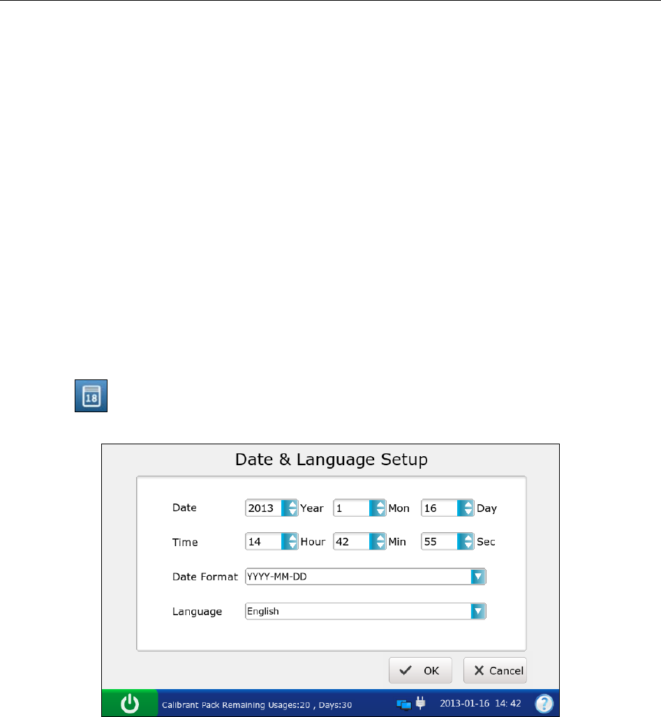
4.2.3 Date & Language Setup
With this menu you can set the time and date, the date format, and the language the analyzer uses
for displays and printouts.
Follow the instructions below to set the date and language:
1. Press to go to the Date & Language Setup screen.
Figure 4-7 Date & Language Setup Screen
2. On the Date & Language Setup screen, you can:
Change the time and date of the system.
Select the date format. There are three formats: MM-DD-YYYY, YYYY-MM-DD and
DD-MM-YYYY. The default is YYYY-MM-DD.
Select the language for displays and printouts. The options are: Simplified Chinese and
English. The default language is English.
3. Press OK to accept the changes, and the system will return to the System Setup screen.
i15 Blood Gas and Chemistry Analysis System User Manual Setup
- 43 -
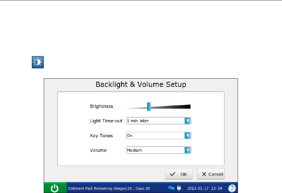
4.2.4 Backlight & Volume Setup
This menu allows you to define the idle time after which the backlight will be automatically
turned off, the brightness of the backlight, the key tones and the volume.
1. Press to go to the Backlight & Volume Setup screen.
Figure 4-8 Backlight & Volume Setup Screen
2. On the Backlight Setup screen, you can:
Adjust the brightness of the backlight with the slider.
Select the idle time after which the backlight will be automatically turned off. The
options are: never, 10 seconds, 1 minute, 3 minutes and 5 minutes. The default setting is
1 minute.
NOTE:
The system will enter standby mode after the backlight is turned off. Press the LCD
screen to resume normal operation mode.
Set the key tones. There are two options: On and Off. If On is selected, and the volume is
not mute, the system will beep after each effective press.
Select the volume of the system. There are four options: High, Medium, Low and Mute.
The default is Medium.
3. Press OK to accept the changes, and the system will return to the System Setup screen.
4.2.5 Diagnostics
This menu lets you diagnose some modules of the analyzer to check its operation. It helps to
troubleshoot.
i15 Blood Gas and Chemistry Analysis System User Manual Setup
- 44 -
NOTE:
Only service engineers and engineers from the manufacturer can perform this action.
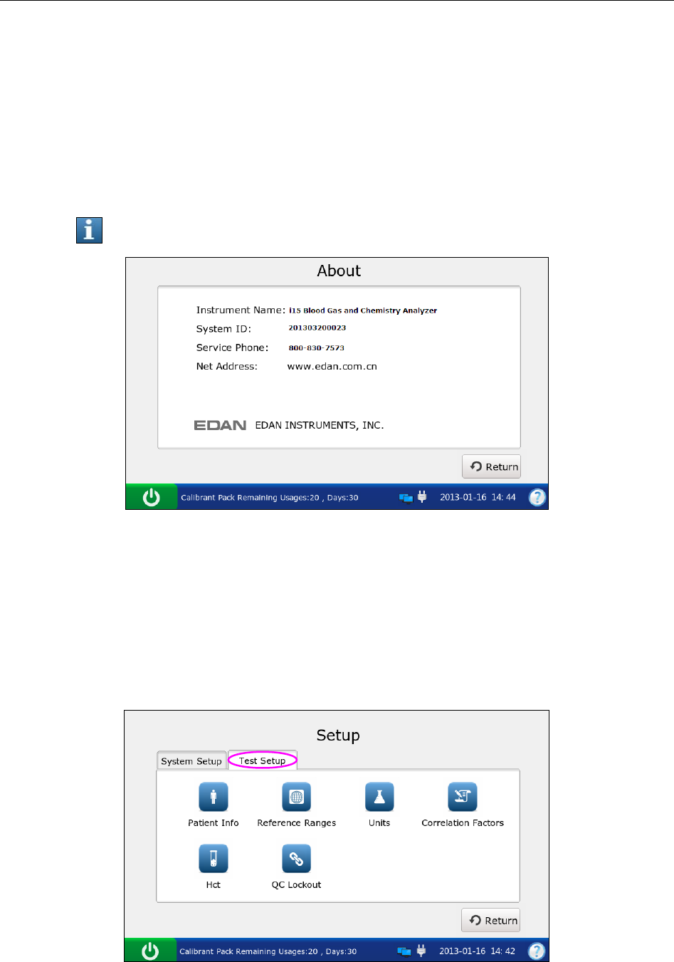
4.2.6 About the Analyzer
The system contains information about your analyzer which makes it convenient for you to know
more about your analyzer and call for technical assistance if necessary.
1. Press to go to the About screen.
Figure 4-9 About Screen
2. View the information on the screen.
3. Press Return to get access to the System Setup screen.
4.3 Test Setup
Press Test Setup on the Setup screen to access the Test Setup screen, and then you can perform
the following operations:
Figure 4-10 Setup – Test Setup Screen
i15 Blood Gas and Chemistry Analysis System User Manual Setup
- 45 -
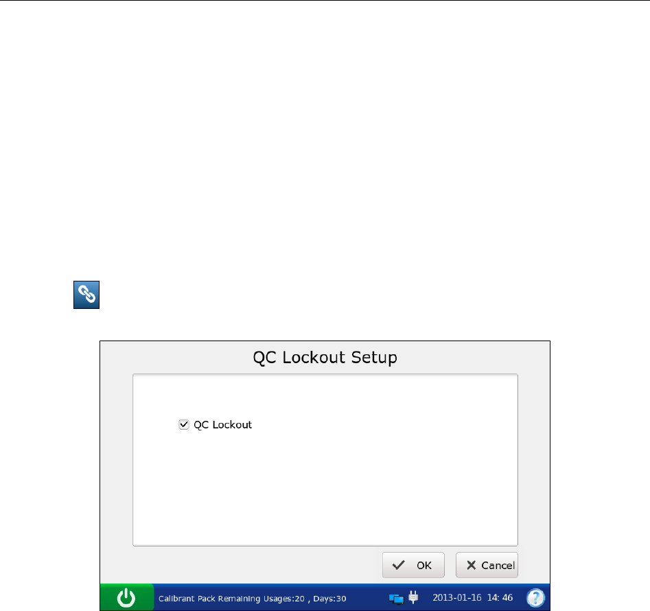
4.3.1 QC Lockout Setup
This menu allows you to configure QC lockout. If QC lockout function is enabled, the system
will not report test results for those parameters that have failed quality control tests, and the
results for these parameters will be flagged with xxx. If QC lockout function is disabled, the
system will report test results for those parameters that have failed quality control tests, and the
test results for these parameters will be flagged with ***. The default setting is enabling QC
Lockout function.
Follow the procedures below to set QC Lockout:
1. Press to go to the QC Lockout Setup screen.
Figure 4-11 QC Lockout Setup Screen
2. Select whether to enable QC Lockout function. √ will appear if QC Lockout function is
enabled.
3. Press OK to accept the changes, and the system will return to the Test Setup screen.
4.3.2 Patient Information Setup
This menu allows you to select which parameters will be displayed on the Edit Patient
Information screen during each patient sample test. The default displayed parameters are patient
ID, temperature, FIO2 and operator ID. The table below lists the parameters for patient
information.

i15 Blood Gas and Chemistry Analysis System User Manual Setup
- 46 -
Table 4-1 Patient Information
Parameter Range Resolution Unit
Patient ID 1 - 16 digits N/A N/A
Operator ID 1 - 16 digits N/A N/A
Sample ID 1 - 16 digits N/A N/A
Temperature 14.0 – 44.0 0.1 °C
57.2 – 111.2 0.1 ℉
Sex Male, Female, / N/A N/A
tHb (Total
hemoglobin)
1.0 – 26.0 0.1 g/dL
10 - 260 1 mg/dL
0.6 – 16.1 0.1 mmol/L
FIO2 0.21 - 1.00 0.01 x.xx
21 - 100 1 %
MCHC (Mean
corpuscular
hemoglobin
concentration)
29.0 - 37.0 0.1 g/dL
290 - 370 1 g/L
RQ (respiratory
quotient) 0.70 - 2.00 0.01 x.xx
Hemoglobin
type Adult, Children, Newborn N/A N/A
Puncture site
LR/RR/LB/RB/LF/RF/Cord/Scalp/LHF/
RHF/LH/RH/AIC, PA Catheter,
CPB or Other, where:
LR=Left Radial
RR= Right Radial
LB= Left Brachial
RB= Right Brachial
LF= Left Femoral
RF= Right Femoral
LHF= Left Hand Finger
RHF= Right Hand Finger
LH= Left Heel
RH= Right Heel
AIC= Arterial Indwelling Catheter
CPB= Cardiopulmonary Bypass
PA Catheter= PA Catheter
Other= Other
N/A N/A
Bypass Pump Off / Pump On N/A N/A
O2 mode
Rm air, Mask, T-P, NC, Vent, Bag, Hood or
Other, where:
Rm Air=Room Air
N/A N/A

i15 Blood Gas and Chemistry Analysis System User Manual Setup
- 47 -
Mask= Mask
T-P= T-Piece
NC= Nasal Cannula
Vent= Ventilator
Bag= Bag (manual resuscitation)
Hood= Hood
Other= Other
I/E Ratio 0.2 - 9.9/0.2 - 9.9 0.1 x.xx
Vent mode
No, SIMV, PSV, PCV, CMV/AC, CPAP,
PCIVR, or BIPAP, where:
No= None
SIMV= Synchronized Intermittent Mandatory
Ventilation
PSV= Pressure Support Ventilation
PCV= Pressure Control Ventilation
CMV/AC= Controlled Mechanical Ventilation/
Assist Control
CPAP= Continuous Positive Airway Pressure
PCIVR= Pressure Control Inverse Ratio
BIPAP= Bi-Level Positive Airway Pressure
N/A N/A
Pplat (Plateau
Pressure) 0 - 100 1 cmH2O
MVol (Minute
Volume) 0 - 120 1 Lpm
PIP (Peak
Inspiratory
Pressure)
0 - 140 1 cmH2O
Liter Flow 0 - 300 1 Lpm
TVol (Tidal
Volume) 0 - 4000 1 mL/kg
PS (Pressure
Support) 0 - 99.9 0.1 cmH2O
PEEP (Positive
End Expiratory
Pressure)
0 - 50 1 cmH2O
Rate 0 - 155 1 Bpm
CPAP
(Continuous
Positive Airway
Pressure)
0 - 50 1 cmH2O
Bi-Level
Pressure 0.2 - 9.9/0.2 - 9.9 0.1 x.xx
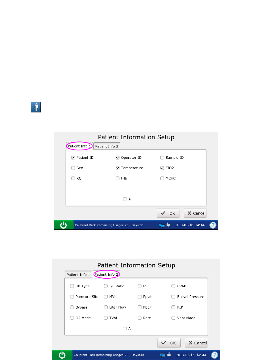
i15 Blood Gas and Chemistry Analysis System User Manual Setup
- 48 -
NOTE:
There is no barometric pressure item in patient information. If the barometric
pressure sensor malfunctions, the system will not report results for the parameters
related to oxygen.
The selected items will be printed out in patient sample reports if Patient Info is
selected in section 4.2.1 Printer Setup.
Follow the instructions below to select which patient information is required:
1. Press to get access to the Patient Information Setup screen.
2. Press Patient Info 1, and select the desired parameters. √ indicates the parameter is selected.
Figure 4-12 Patient Information 1 Screen
3. Press Patient Info 2, and select the desired parameters. √ indicates the parameter is selected.
Figure 4-13 Patient Information 2 Screen
NOTE:
Select All to select all the parameters at each screen.
4. Press OK to accept the changes, and the system will return to the Test Setup screen.
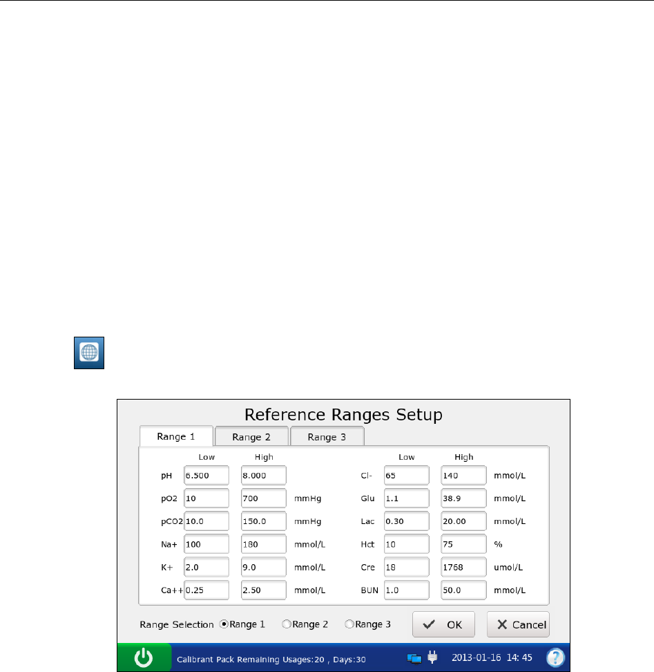
i15 Blood Gas and Chemistry Analysis System User Manual Setup
- 49 -
4.3.3 Reference Ranges Setup
With this menu you can set the reference range for each measured parameter. There are three
options: Reference Range 1, Reference Range 2, and Reference Range 3. The default is
Reference Range 1. A result that is out of the reference range will be flagged with an up/down
arrow. Reference ranges are factory set to be the measurement ranges for each measured
parameter. Values outside reference ranges are not flagged with an up/down arrow. Therefore
reference ranges must be set according to internal procedures at your individual institution.
Because reference ranges may vary with demographic factors such as age, gender and heritage, it
is recommended that reference ranges be set according to the population being tested.
Follow the instructions below to set the reference ranges:
1. Press to access the Reference Ranges Setup screen.
Figure 4-14 Reference Ranges Setup Screen
2. Select the desired reference range, and edit the limits for those parameters you want to
change.
3. Press OK to accept the changes, and the system will return to the Test Setup screen.
NOTE:
If unacceptable values are entered, the system will display the correct range.
The limits entered will be saved in the system even after the system is shut down.

i15 Blood Gas and Chemistry Analysis System User Manual Setup
- 50 -
4.3.4 Units Setup
This function allows you to select the units for measured parameters, calculated parameters and
parameters of patient information.
Table 4-2 Units for Parameters
Parameter Default Unit Alternate Units
Ca
++
mmol/L mg/dL
pCO2 mmHg kPa
pO
2
mmHg kPa
Glu mmol/L mg/dL
Lac mmol/L mg/dL
Hct % x.xx
Cre μmol/L mg/dL
BUN mmol/L mg/dL
tHb(est) g/dL g/L,mmol/L
sO2(est) % x.xx
pO2(A-a) mmHg kPa
pO2(a/A) x.xx %
RI x.xx %
pO2/FIO2 mmHg mmHg/%, kPa, kPa/%
Ca
++
(7.4) mmol/L mg/dL
pCO2(T) mmHg kPa
pO2(T) mmHg kPa
pO2(A-a)(T) mmHg kPa
pO2(a/A)(T) x.xx %
RI(T) x.xx %
pO2(T)/FIO2 mmHg mmHg/%, kPa, kPa/%
Temperature °C ℉
FIO
2
x.xx %
tHb g/dL g/L, mmol/L
MCHC g/dL g/L
Baro/Partial Pressure mmHg kPa
Follow the directions below to select the desired units for the parameters:
1. Press to get access to the Units Setup screen.
2. Press Units 1, and select the desired units for the parameters whose units you want to
change.
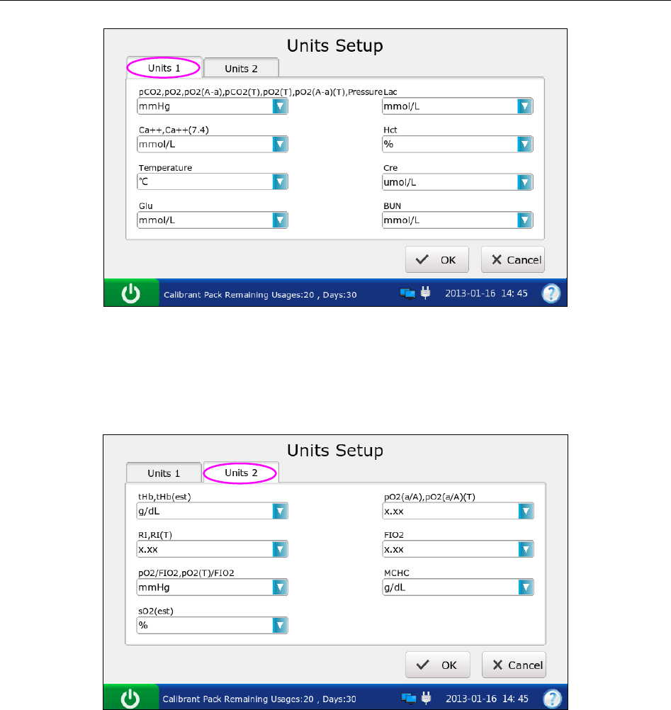
i15 Blood Gas and Chemistry Analysis System User Manual Setup
- 51 -
Figure 4-15 Units Setup 1 Screen
3. Press Units 2, and select the desired units for the parameters whose units you want to
change.
Figure 4-16 Units Setup 2 Screen
4. Press OK to accept the changes, and the system will return to the Test Setup screen.
NOTE:
The results stored in the system are automatically converted to match new units.
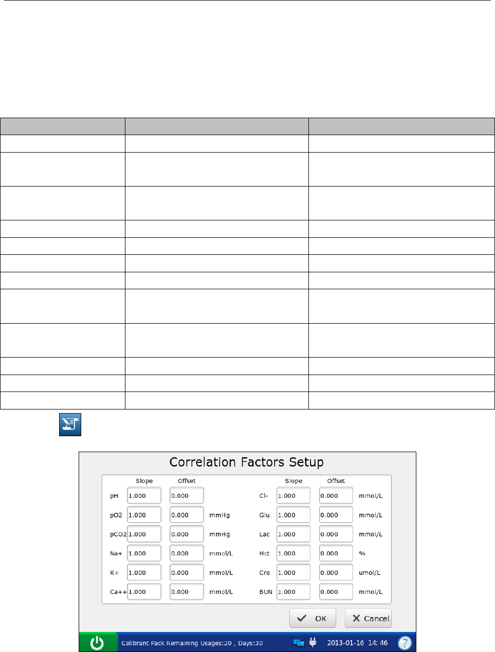
i15 Blood Gas and Chemistry Analysis System User Manual Setup
- 52 -
4.3.5 Correlation Factors Setup
Correlation factors allow you to correlate results obtained from the system to results obtained
from another system. The ranges for the slope and offset of each parameter are listed in table 4-3.
Table.4-3 Correlation Factors
Parameter Slope Range Offset Range
pH 1.200 – 0.800 +/- 1.000
pCO2 1.200 – 0.800 +/- 10.0 mmHg
+/- 1.33 kPa
pO2 1.200 – 0.800 +/- 40 mmHg
+/- 5.33 kPa
Na
+
1.200 – 0.800 +/-30.0 mmol/L
K
+
1.200 – 0.800 +/- 1.00 mmol/L
Cl
-
1.200 – 0.800 +/- 20.0 mmol/L
Ca
++
1.200 – 0.800 +/- 0.500 mmol/L
Glu 1.200 – 0.800 +/- 50.0 mg/dL
+/- 2.78 mmol/L
Lac 1.200 – 0.800 +/- 4.00 mmol/L
+/- 36.0 mg/dL
Cre 1.200 – 0.800 +/- 30 umol/L
BUN 1.200 – 0.800 +/- 1.8 mmol/L
Hct 1.200 – 0.800 +/- 20 % PCV
1. Press to get access to the Correlation Factors Setup screen.
Figure 4-17 Correlation Factors Setup Screen
2. Edit the values of the slopes and offsets for the parameters whose correlation factors you
want to change.
3. Press OK to accept the changes, and the system will return to the Test Setup screen.
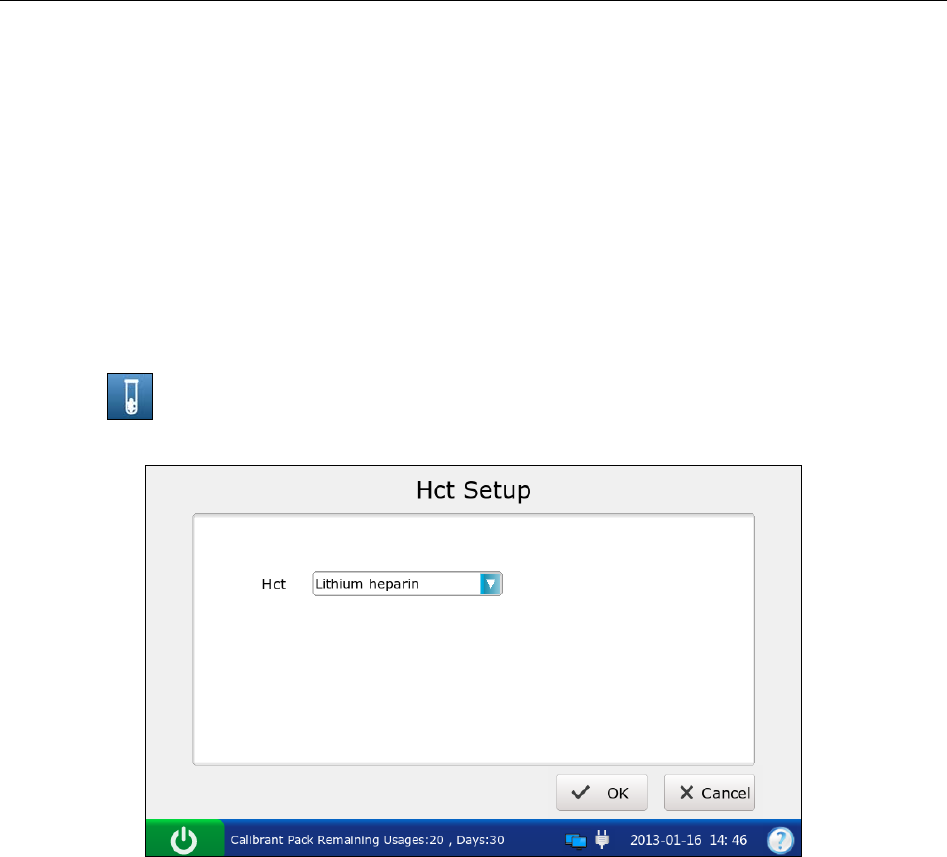
i15 Blood Gas and Chemistry Analysis System User Manual Setup
- 53 -
NOTE:
The default value is 1.0 for all slopes and 0.0 for all offsets.
Changing correlation factors affects future test results, but does not affect past,
stored test results.
4.3.6 Hct Setup
When only Hct levels are measured for whole blood samples, this menu allows you to select the
anticoagulants.
1. Press to get access to the Hct Setup screen.
Figure 4-18 Hct Setup Screen
2. Select the desired anticoagulant. There are three options: K2EDTA, K3EDTA, lithium heparin.
The default is lithium heparin.
3. Press OK to accept the changes, and the system will return to the Test Setup screen.
i15 Blood Gas and Chemistry Analysis System User Manual Patient Analyzing
- 54 -
Chapter 5 Patient Analyzing
NOTE:
Take safety measures when working with biological samples, such as wearing
approved gloves, etc.
5.1 Sample Collection and Preparation
5.1.1 Sample Collection
Blood samples should be collected according to proper medical guidelines containing collection
details, such as site selection, collection procedures, sampling devices, sample handling, etc.
Sterile techniques should be followed to prevent the site from being contaminated.
Handle blood samples and collection devices with care, and wear approved protective
gloves to avoid direct contact with samples.
WARNING
NOTE:
Only fresh whole blood samples are recommended for use.
When taken for electrolyte analysis, venous samples should not be collected from a
central venous catheter containing silver sulfadiazine or chlorhexidine, because they
have a great influence on sodium levels.
Samples should be collected by trained professionals.
For mixed venous samples, the system reports only pO2 result.
5.1.2 Anticoagulants
Only those sample devices containing the proper amount of calcium-titrated (balanced) heparin or
lithium heparin as the anticoagulant should be used to collect whole blood samples. If
calcium-titrated (balanced) heparin is used as an anticoagulant, the minimum heparin-to-blood
ratio should be 2.3 units of heparin per 1.0mL of blood sample. If a sample is analyzed for
ionized calcium, the maximum heparin-to-blood ratio should be 15 units of heparin per 1.0mL of
blood sample; if not, the maximum heparin-to-blood ratio should be 50 units of heparin per
1.0mL of blood sample.
If there are clots in the blood sample, discard it and collect samples again.
CAUTION

i15 Blood Gas and Chemistry Analysis System User Manual Patient Analyzing
- 55 -
NOTE:
Don’t use the following anticoagulants: EDTA, citrate, and oxalate, because they have a
great influence on test results for pH and electrolytes.
5.1.3 Collection Devices and Volume
Samples can be introduced into the system with the following devices: syringes and capillary
tubes. It is recommended that VITREX® Blood Gas Capillary Tubes with a minimum volume,
filled of 175μL (Article Number: 182413) should be used.
NOTE:
The system uses 110μL samples for analysis, and make sure it can aspirate enough
sample.
The minimum fill volume for a 1mL syringe is 200μL.
The minimum fill volume for a 2mL syringe is 800μL.
The minimum fill volume for a 5mL syringe is 1.5mL.
Dislodge bubbles from the syringe, and cover it as soon as the sample is collected.
Cork should never be used to cover the syringe.
A capillary tube should be filled to capacity and covered securely. Cork or clay should
never be used to cover the capillary tube.
5.1.4 Notes
Follow the notes below to ensure that test results are accurate:
1. Cover the sample device immediately after collection to prevent it from being
contaminated by air.
2. Mix blood samples thoroughly prior to sample introduction.
3. Make sure there are no clots in blood samples, or else the results will be inaccurate.
4. Perform the sample test immediately after its collection to get the most accurate
results. Measure samples for blood gases and Ca++ within 10 minutes, and measure
samples for other analytes within 30 minutes.
5. Used sample devices are biohazardous waste, and should be handled abiding by
local regulatory guidelines.
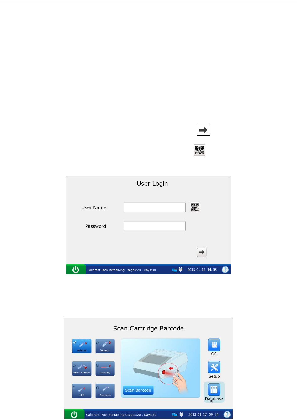
i15 Blood Gas and Chemistry Analysis System User Manual Patient Analyzing
- 56 -
5.2 Patient Analyzing
NOTE:
Ensure that the displayed date and time are correct before each sample test, because
they are part of the patient sample data. Contact the administrator if the date and/or time
are incorrect.
5.2.1 Procedures for Patient Analyzing
1. Press the On/Off button on the left hand side of the analyzer to turn it on.
2. Enter the user name and password manually, and then press .
To enter the user name with the bar code scanner, press first, and then scan the user
name bar code.
Figure 5-1 Enter User Name and Password
3. Press the button for the blood sample type on the Main screen. √ will appear if the button is
selected. The default type is Arterial.
Figure 5-2 the Main Screen
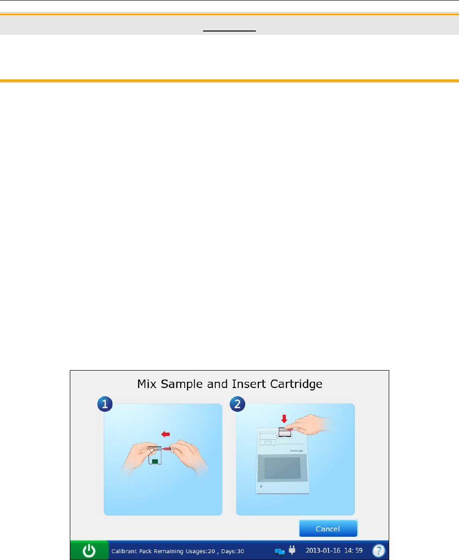
i15 Blood Gas and Chemistry Analysis System User Manual Patient Analyzing
- 57 -
CAUTION
Make sure that the selected sample type button is consistent with the blood sample, or
the result may be inaccurate.
4. Press Scan Barcode, and scan the bar code on a new cartridge foil pouch.
If the bar code is scanned successfully, the system will beep and the scanner will be
automatically turned off. If the scanned data is valid, the system will display the screen for
the next procedure. If the scanned data is invalid, a message will pop up to prompt you.
5. Open the foil pouch and remove the cartridge from it.
NOTE:
Avoid tearing the bar code on the foil pouch.
For sample introduction with a capillary tube, insert a capillary adaptor into the fillport
after removing the cartridge.
6. Roll the syringe or capillary tube between palms and gently invert it end over end for several
times to mix the sample completely.
Figure 5-3 Mix Sample and Insert Cartridge
NOTE:
To avoid inaccurate test results, mix the sample thoroughly prior to sample
introduction.
To avoid inaccurate test results, make sure there are no trapped bubbles or clots in
the sample.
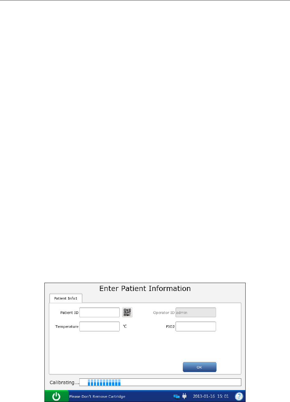
i15 Blood Gas and Chemistry Analysis System User Manual Patient Analyzing
- 58 -
7. Insert the syringe or capillary tube into the fillport of the cartridge.
NOTE:
When using a syringe, discard the first 2 drops of blood sample first, then remove the
needle from it, and finally insert it into the fillport.
When using a capillary tube, insert the capillary tube into the adaptor till the tube
reaches the interface between the adaptor and the cartridge.
8. Gently insert the cartridge into the cartridge port, and carefully press down to ensure it clicks
into place.
For a valid cartridge, the indicator in the cartridge port will turn green, and the system will
automatically aspirate calibrant. For an invalid cartridge, the indicator will turn red, the
cartridge will be ejected and a message will pop up to prompt you.
NOTE:
Never inject the sample. It will be aspirated automatically.
The cartridge can not be removed from the analyzer until the measurement is
complete.
9. Enter patient information. The screen displayed depends on the selection in section 4.3.2
Patient Information Setup. The screen for the default patient information setup is shown
below:
Figure 5-4 Enter Patient Data
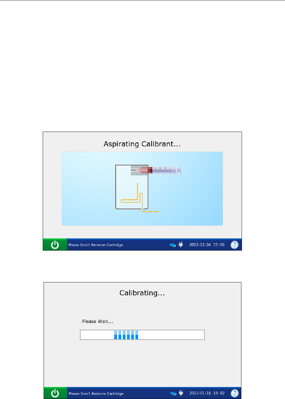
i15 Blood Gas and Chemistry Analysis System User Manual Patient Analyzing
- 59 -
NOTE:
It is not necessary to enter all the above parameters. You can press OK at any time.
If no parameters are selected in section 4.3.2 Patient Information Setup, the system
will go to the Aspirating Calibrant screen when the test cartridge is properly inserted.
The system can not go back to the screen for entering patient information after you
press OK, and patient information has to be edited in the patient sample database.
10. Press OK. The system will go to the following screens:
a). If the system is aspirating calibrant, the system will go to the following screen:
Figure 5-5 Aspirating Calibrant…
b). If the system is calibrating sensors, the system will go to the screen below:
Figure 5-6 Calibration in Progress
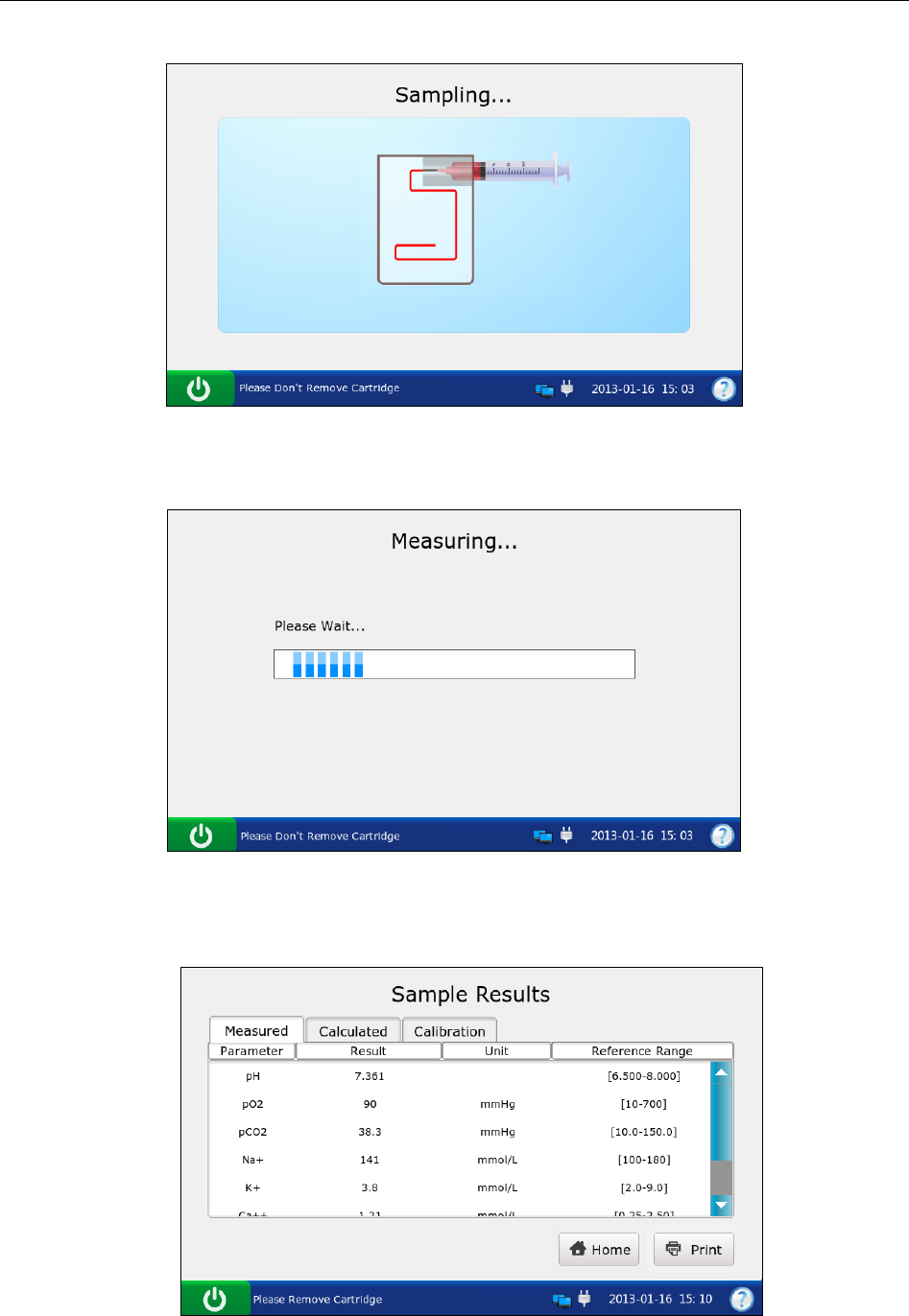
i15 Blood Gas and Chemistry Analysis System User Manual Patient Analyzing
- 60 -
c). If the system is sampling, the system will go to the screen below:
Figure 5-7 Sampling…
d). If the system is analyzing patient samples, the system will go to the screen below:
Figure 5-8 Measurement in Progress
e). If the test is complete, the system will go to the screen below:
Figure 5-9 Sample Results
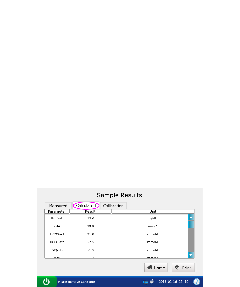
i15 Blood Gas and Chemistry Analysis System User Manual Patient Analyzing
- 61 -
NOTE:
Upon the completion of the test, the indicator in the cartridge port will be off, the
message “Please Remove Cartridge” will be displayed on the status bar at the
bottom of the screen, and the cartridge will be ejected.
If the screen has not been touched for 10 seconds after the test is complete, the test
results will be displayed automatically even if you do not press OK.
If patient temperature is entered, the test results will be displayed both at 37°C and at
the patient’s temperature.
If Auto Transmit is turned on in section 4.2.2 Network Setup, patient sample results
will be transmitted to the DMS automatically.
If Auto Print is selected in section 4.2.1 Printer Setup, patient sample results will be
printed automatically. If it is not selected, press Print to print the test results.
11. View the test results. The system displays the results for measured parameters by default.
Press Calculated to view the results for calculated parameters.
Figure 5-10 Calculated Parameters
Press Calibration to view the calibration results.
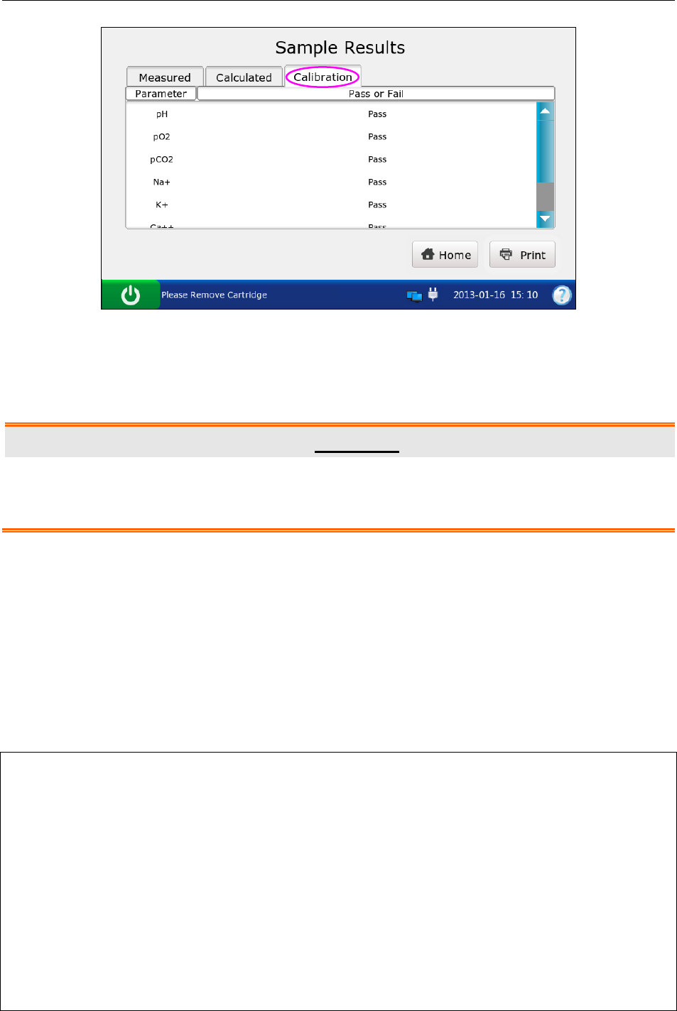
i15 Blood Gas and Chemistry Analysis System User Manual Patient Analyzing
- 62 -
Figure 5-11 Calibration Parameters
Symbols such as > may appear on the Results screen, refer to section 5.2.2 Understanding Result
Symbols to understand their meanings.
WARNING
Never make treatment decisions according to test results containing symbols as
described in section 5.2.2 Understanding Result Symbols.
12. Remove the test cartridge from the system.
13. Press Home to return to the Main screen.
The contents of a patient sample report depend on the type of the test cartridge you have used, the
options selected in section 4.2.1 Printer Setup and section 4.3.2 Patient Information Setup, and
the errors and alarms the system detects during the measurement. The table below is an example
of a patient sample report:
EDAN i15
System ID 201303200023
Report Type Patient Sample Report
Sample Type Arterial
Print Time 2012-03-20 15:20:00
Test Time 2012-03-20 15:10:00
Patient ID 88888
Operator ID 55555
Patinet Information

i15 Blood Gas and Chemistry Analysis System User Manual Patient Analyzing
- 63 -
Temperature 37 ℃
Sex Female
tHb 30 g/dL
FIO2 20
MCHC g/dL
RQ
Hb type Adult
Puncture site LR (Left Radial)
Bypass Pump Off
O2 mode
I/E Ratio 0/0
Vent mode None
......
Calibration Results
pH Fail
p
CO2 Pass
p
O2 Pass
Na+ Pass
K+ Pass
Ca++ Pass
Cl- Pass
Glu Pass
Lac Pass
Hct Pass
Cre Pass
BUN Pass
Results for Measured Parameters
pH ---
p
CO2 xxx mmHg
p
O2 70 mmHg
Na+ ??? mmol/L
K+ 1.0 ↓ mmol/L
Ca++ 200 ↑ mmol/L
Cl- > mmol/L
Glu < mmol/L
Lac 5 *** mmol/L
…
Results for Calculated Parameters
cH+ 1 nmol/L
pH(T) 1

i15 Blood Gas and Chemistry Analysis System User Manual Patient Analyzing
- 64 -
p
CO2(T) 1 ***
p
O2(T) 1 >
HCO3
-act 1 <
HCO3
-std 1
BE(ecf) 1
Ca++(7.4) 1
…
Reference Ranges
pH [7.35 - 7.45]
p
CO2 [35.0 - 45.0] mmHg
p
O2 [80.0 - 100.0] mmHg
Na+ [138.0 - 146.0] mmol/L
K+ [3.50 - 4.90] mmol/L
Ca++ [1.12 - 1.32] mmol/L
Cl- [98 - 109] mmol/L
Glu [3.9 - 5.8] mmol/L
Lac [0.36 - 1.7] mmol/L
Hct [35 – 51] %
Cre [0.6 - 1.3] mg/dL
BUN
5.2.2 Understanding Result Symbols
The following table shows the symbols that may appear on the screen:
Symbol Description
> or < The result is above or below the measurement range.
↑ or ↓ The result is above or below the reference range.
--- The measured parameter fails calibration.
xxx The measured parameter fails quality control (QC) tests, and QC lockout function is
enabled in Setup.
***
The measured parameter fails quality control (QC) tests, and QC lockout function is
disabled in Setup.
The result for the calculated parameter is valid, but the measured parameter used to
determine this calculated parameter fails quality control (QC) tests, and QC lockout
function is disabled in Setup.
??? The result for the measured parameter is invalid.
NOTE:
Invalid test result for a calculated parameter will not be displayed on the screen.
Valid test result for a calculated parameter will not be displayed on the screen, if the
measured parameter used to determine the result fails quality control (QC) tests, and
QC lockout function is enabled in Setup.
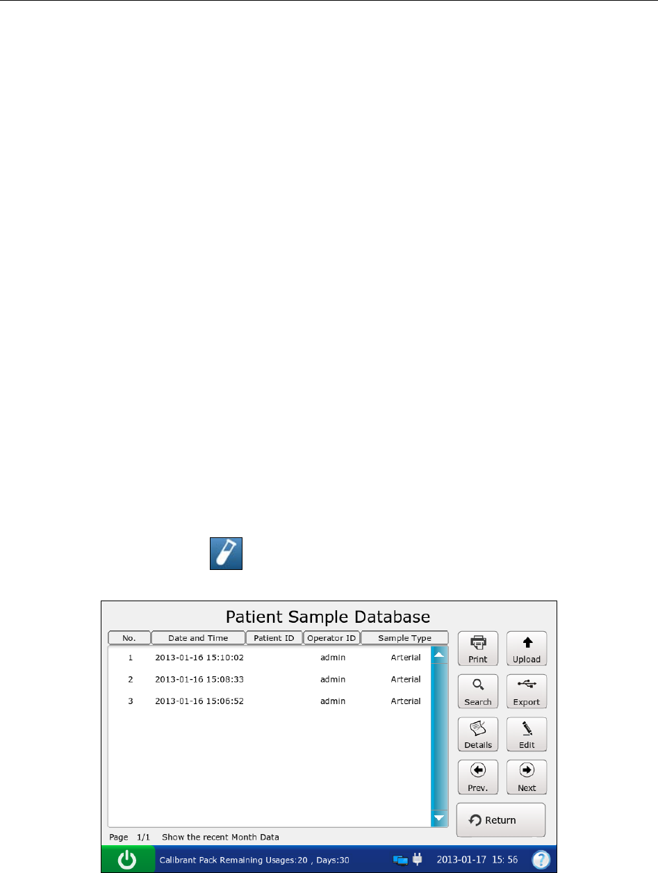
i15 Blood Gas and Chemistry Analysis System User Manual Patient Analyzing
- 65 -
5.3 Patient Sample Database
The patient sample database displays patient sample data for the most recent month by default,
and it can store up to 10000 data entries. The system displays 50 pieces of data on every page.
Press Prev. and Next to page through the screens of the displayed data entries. When 80% of the
space is occupied, the system will prompt you to export the stored data to a removable disk (such
as a USB drive). If data is not exported, the system will continue to save new data. When the
database is full, the system will always prompt you to export data. If data is still not exported, the
system will automatically delete the oldest one to accommodate a new one. The following
operations can be performed in the patient sample database: transmitting patient sample data to
the Data Management System (DMS) through WIFI or the network, exporting patient sample
data to a removable disk (such as a USB drive), viewing the details of patient sample data, editing
patient information, searching for and printing patient sample data, etc.
NOTE:
Only patient information data can be edited.
Test results for calculated parameters may be changed due to the alteration of patient
information data.
On the Database screen, press to access the Patient Sample Database screen.
Figure 5-12 Patient Sample Database Screen
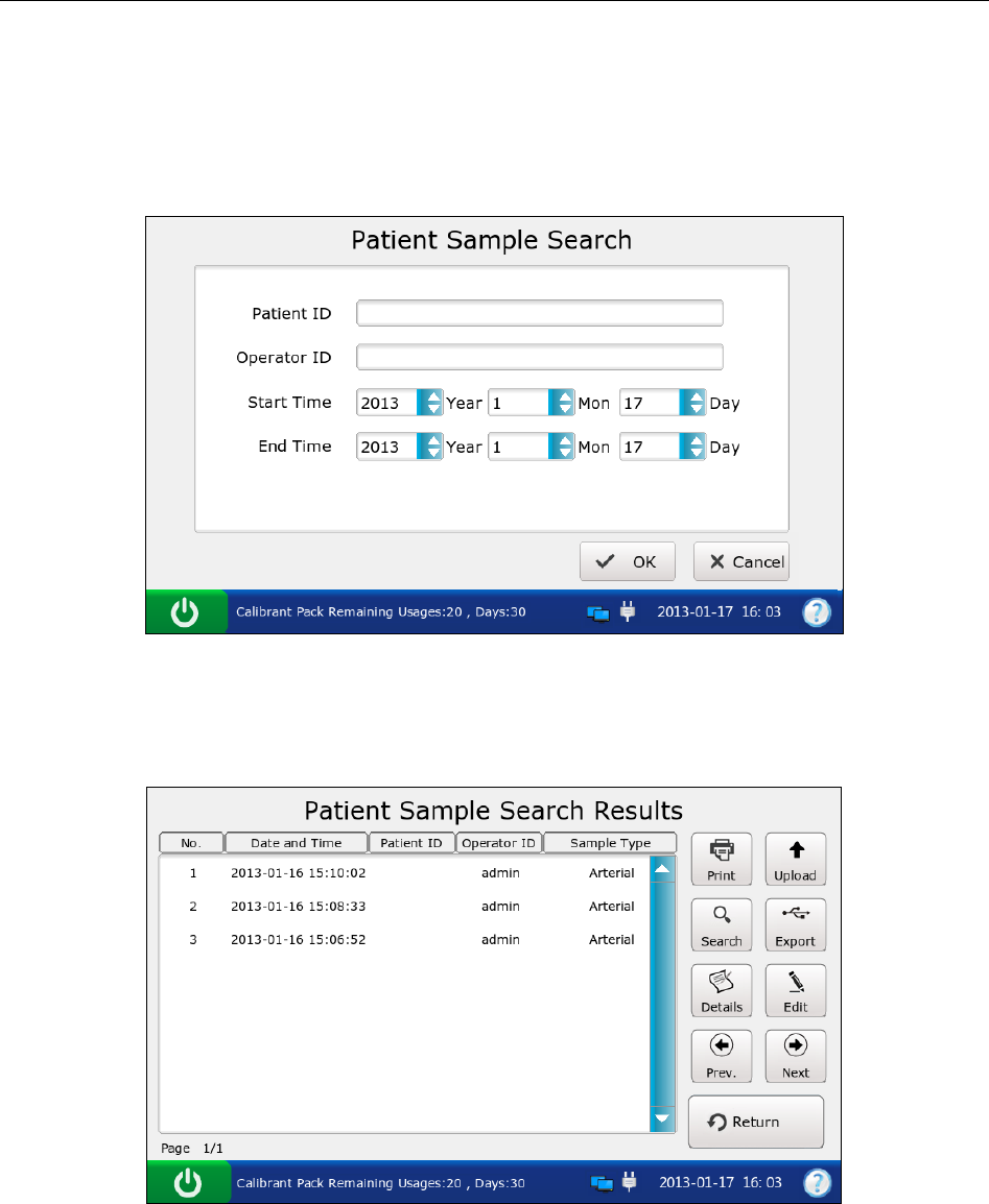
i15 Blood Gas and Chemistry Analysis System User Manual Patient Analyzing
- 66 -
5.3.1 Searching for Patient Sample Data
1. On the Patient Sample Database screen, press Search.
2. Enter the search conditions, and press OK.
Figure 5-13 Enter Search Conditions
3. The system automatically begins the search and displays the results.
Figure 5-14 Search Results
4. Press Return to go back to the Patient Sample Database screen.
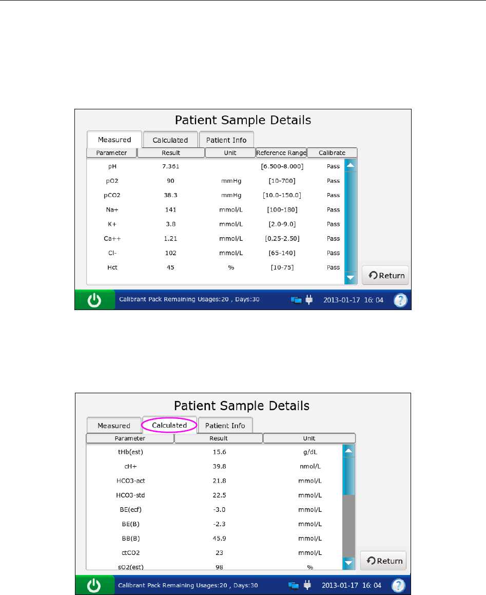
i15 Blood Gas and Chemistry Analysis System User Manual Patient Analyzing
- 67 -
5.3.2 Viewing Details of Patient Sample Data
1. Press the patient sample data you want to view.
2. Press Details. The system displays the details of measured parameters by default.
Figure 5-15 Details of Measured Parameters
3. Press Calculated to view the details of calculated parameters.
Figure 5-16 Details of Calculated Parameters
4. Press Patient Info to view the details of patient information.
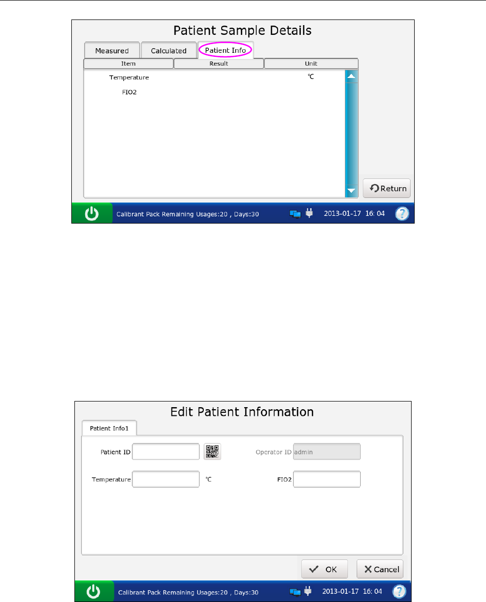
i15 Blood Gas and Chemistry Analysis System User Manual Patient Analyzing
- 68 -
Figure 5-17 Details of Patient Information
5. Press Return to go back to the Patient Sample Database screen.
5.3.3 Editing Patient Information Data
1. Select the desired patient sample data, and then press Edit.
2. Edit the patient information data. The following screen will be displayed for the default
patient information setup:
Figure 5-18 Edit Patient Data
NOTE:
The screen displayed depends on the selection in section 4.3.2 Patient Information
Setup.
3. Press OK to save the changes, and the system will return to the Patient Sample Database
screen.

i15 Blood Gas and Chemistry Analysis System User Manual Patient Analyzing
- 69 -
5.3.4 Exporting/Uploading/Printing Patient Sample Data
1. Open the patient sample database.
2. Select the desired patient sample data.
To Do this
Export Insert a removable disk into the analyzer, and then press Export.
Upload Press Upload.
Print Press Print.
NOTE:
If no patient sample data is selected before pressing Export/Upload/Print, all of the data
stored in the patient sample database will be exported/uploaded/printed.
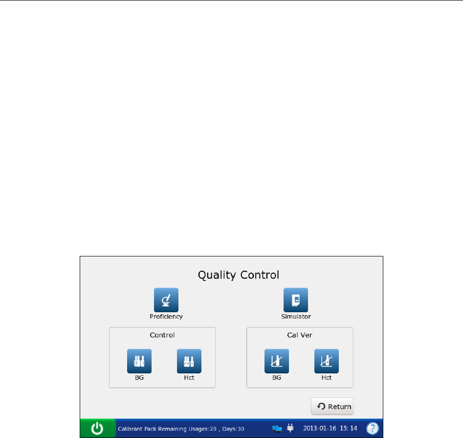
i15 Blood Gas and Chemistry Analysis System User Manual Quality Control (QC) Tests
- 70 -
Chapter 6 Quality Control (QC) Tests
Quality Control (QC) tests could ensure the normal operation of the system and the reliability of
test results. Policies related to the measurement of QC samples are at the discretion of your
individual institution. It is recommended to perform QC tests in the following situations:
You are using the system for the first time.
You wish to verify the performance of newly received test cartridges.
You wish to verify the storage condition of test cartridges.
You wish to verify the performance of the system.
You doubt test results.
Figure 6-1 Quality Control Screen
6.1 Control Test
Control tests are intended to verify the efficient performance of the system. To verify the
performance of each lot of newly received test cartridges, analyze at least two levels of controls
in duplicate using a verified analyzer.
6.1.1 Controls
Controls are intended for use to monitor test cartridge performance at multiple points within the
clinical range. Controls used are RNA Medical® QC823 Blood
Gas●Electrolyte●Metabolite●BUN controls and RNA Medical® QC900 Hematocrit controls. The
concentrations of reactive ingredients in various levels of controls are known. Controls do not
contain human serum or serum products, but do contain buffers and preservatives. Acceptable

i15 Blood Gas and Chemistry Analysis System User Manual Quality Control (QC) Tests
- 71 -
ranges for controls specific to the i15 Blood Gas and Chemistry Analysis System are
programmed in the bar code on the user manual for controls provided by EDAN.
Packaging
1. RNA Medical® QC823 Blood Gas●Electrolyte●Metabolite●BUN controls are contained in
2.5mL glass ampoules, and RNA Medical® QC900 Hematocrit controls are contained in
1.7mL glass ampoules.
2. The controls package contains information such as the control name, level, lot number and
expiration date, etc.
Storage and Usage
Controls should be stored at 2 - 8°C (avoid freezing) with the relative humidity of 25% - 93%
(non-condensing).
Controls should be used at 10 - 31°C with the relative humidity of 25% - 80% (non-condensing).
Before Use
Controls should be equilibrated to room temperature before use. If oxygen is to be measured, the
ampoule needs to stand at room temperature for 4 hours. If not, the ampoule needs to stand at
room temperature for only about 30 minutes.
Immediately before use, mix controls completely by shaking the ampoule gently, and always hold
an ampoule at tip and at bottom with forefinger and thumb to minimize increasing controls
temperature. Tap the tip of the ampoule carefully with your fingernail to remove any solution.
NOTE:
Store and use controls according to the user manual, and use them before the
expiration date as labeled on the package.
Only controls provided by EDAN or its authorized distributors should be used.
For test cartridges with pH, pCO2, pO2, Ca++ sensors, a new ampoule and syringe or
capillary tube should be used for each test. For test cartridges without pH, pCO2, pO2,
Ca++ sensors, the remaining solution can still be used if the ampoule is opened within
10 minutes.
The test results should fall within the acceptable ranges programmed in the bar code
on the user manual for controls provided by EDAN.
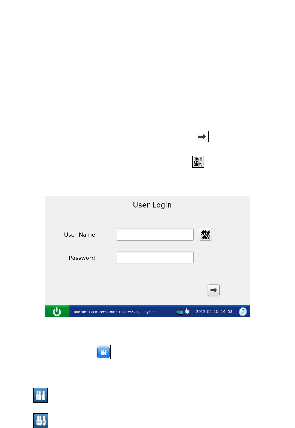
i15 Blood Gas and Chemistry Analysis System User Manual Quality Control (QC) Tests
- 72 -
6.1.2 Procedures for Control Test
Follow the steps below to perform a control test:
1. Examine the package label of controls to ensure they have not expired.
2. Remove an ampoule from the box of controls and equilibrate it to room temperature.
If oxygen is to be measured, the ampoule needs to stand at room temperature for 4 hours. If
not, the ampoule needs to stand at room temperature for only about 30 minutes.
3. Press the On/Off button on the left hand side of the analyzer to turn it on.
4. Enter the user name and password manually, and then press .
To enter the user name with the bar code scanner, press first, and then scan the user
name bar code.
Figure 6-2 Enter User Name and Password
5. On the Main screen, press to go to the Quality Control screen.
6. Select the desired control type.
Press to perform a control test for blood gases and electrolytes.
Press to perform a control test for Hct.
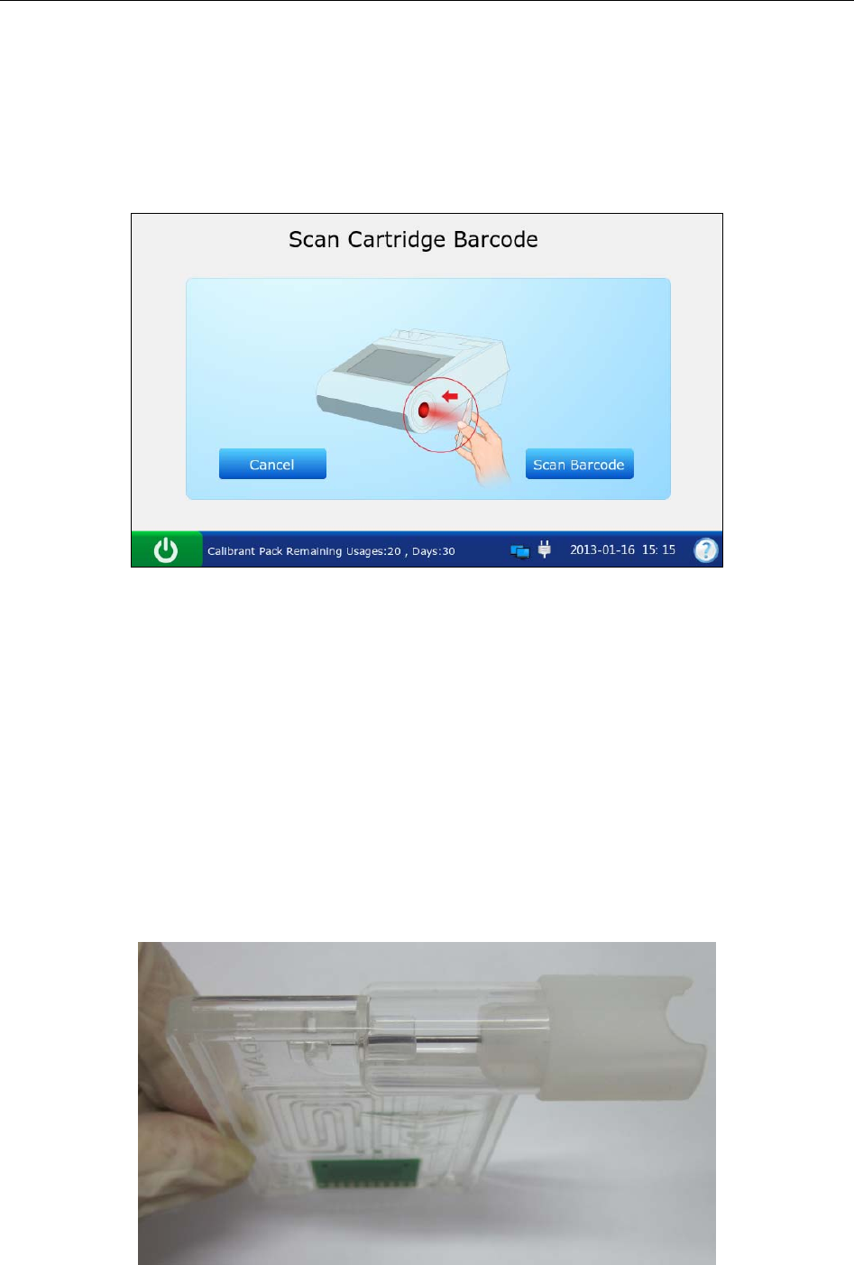
i15 Blood Gas and Chemistry Analysis System User Manual Quality Control (QC) Tests
- 73 -
7. Press Scan Barcode, and scan the bar code on a new cartridge foil pouch.
If the bar code is scanned successfully, the system will beep and the scanner will be
automatically turned off. If the scanned data is valid, the system will display the screen for
the next procedure. If the scanned data is invalid, a message will pop up to prompt you.
Figure 6-3 Scan Bar Code
8. Open the foil pouch and remove the cartridge from it.
NOTE:
Avoid tearing the bar code on the foil pouch.
For sample introduction with a capillary tube or an ampoule, insert a capillary
adaptor/ampoule adaptor into the fillport after removing the cartridge.
When inserting an ampoule adaptor into the fillport of a test cartridge, make sure the
indent of the adaptor is on the upside as shown in the picture below:
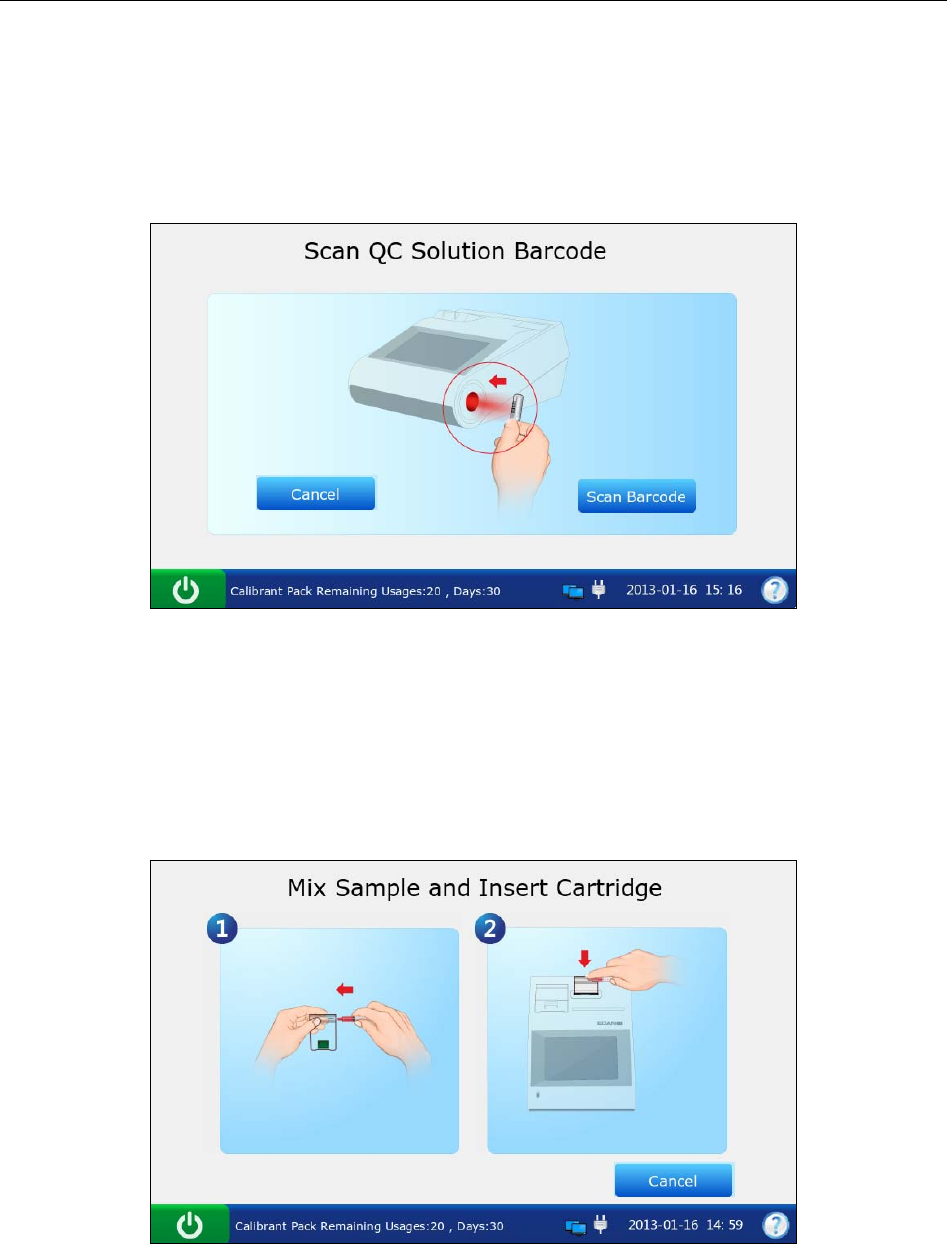
i15 Blood Gas and Chemistry Analysis System User Manual Quality Control (QC) Tests
- 74 -
9. Press Scan Barcode, and scan the bar code on the controls user manual.
If the bar code is scanned successfully, the system will beep and the scanner will be
automatically turned off. If the scanned data is valid, the system will display the screen for
the next procedure. If the scanned data is invalid, a message will pop up to prompt you.
Figure 6-4 Scan Bar Code
NOTE:
Keep the controls user manual for a future control test use.
10. Mix the controls completely by shaking the ampoule gently, and then tap the tip of the
ampoule carefully with your fingernail to remove any solution.
Figure 6-5 Mix Controls and Insert Cartridge
NOTE:
Avoid heating the ampoule with your hands when shaking the ampoule.

i15 Blood Gas and Chemistry Analysis System User Manual Quality Control (QC) Tests
- 75 -
11. Open the ampoule by snapping off the top and immediately transfer control solution by
slowly drawing an appropriate amount of solution with a syringe or capillary tube from the
bottom of the ampoule.
NOTE:
When using an ampoule for sample introduction, you need not transfer control
solution. Insert the ampoule into the adaptor after opening it, and directly go to step
13.
Take protective measures when opening the ampoule, such as using gloves, tissue,
etc.
12. Insert the syringe or capillary tube into the fillport of the cartridge.
NOTE:
When using a syringe, discard the first 2 drops of solution first, then remove the
needle from it, and finally insert it into the fillport.
When using a capillary tube, directly insert the capillary tube into the adaptor till the
tube reaches the interface between the adaptor and the cartridge.
To avoid inaccurate test results, make sure there are no bubbles in the sample. If
bubbles continually exist, use a new ampoule and syringe or capillary tube to collect
samples again.
13. Gently insert the cartridge into the cartridge port, and carefully press down to ensure that it
clicks into place.
For a valid cartridge, the indicator in the cartridge port will turn green, and the system will
automatically aspirate calibrant. For an invalid cartridge, the indicator will turn red, the
cartridge will be ejected and a message will pop up to prompt you.
NOTE:
The cartridge can not be removed from the analyzer until the measurement is
complete.
Never inject the sample. It will be aspirated automatically.
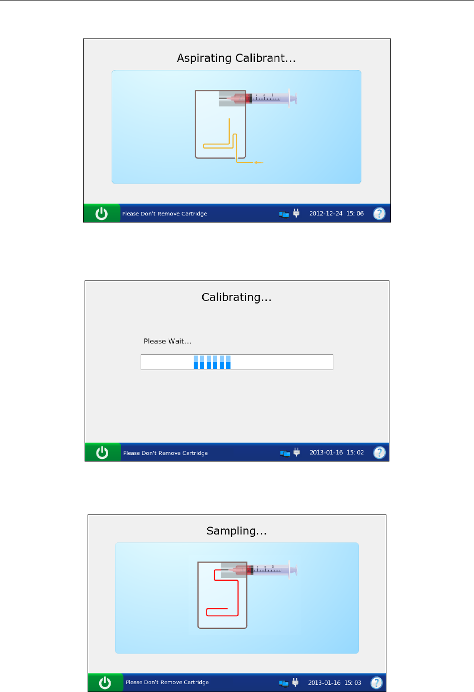
i15 Blood Gas and Chemistry Analysis System User Manual Quality Control (QC) Tests
- 76 -
14. The system automatically aspirates calibrant.
Figure 6-6 Aspirating Calibrant…
15. The system automatically performs calibration.
Figure 6-7 Calibration in Progress
16. The system automatically aspirates samples when calibration is complete.
Figure 6-8 Sampling…
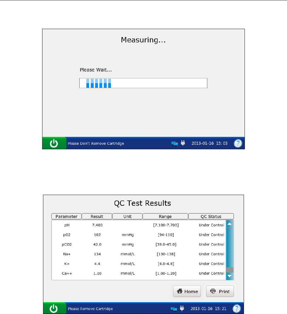
i15 Blood Gas and Chemistry Analysis System User Manual Quality Control (QC) Tests
- 77 -
17. The system automatically analyzes the sample upon the completion of sampling.
Figure 6-9 Measurement in Progress
18. The system automatically displays the test results upon the completion of the test.
Figure 6-10 Control Test Results
19. View the results.
NOTE:
The system will indicate whether the results are within or outside the acceptable
ranges with Under Control/Out of Control.
If a parameter fails calibration, the system will not be able to determine whether it is
under control, and will display Calibration Failure to prompt you.

i15 Blood Gas and Chemistry Analysis System User Manual Quality Control (QC) Tests
- 78 -
The system will not report the result for a parameter failing the control test in the
patient sample analysis, if QC Lockout function is enabled in Setup. To report the
result for the parameter, repeat the control test till the parameter passes it.
If the results are outside the acceptable ranges, check the following items first, and
then perform another test.
Refer to the user manual to confirm that the test procedures are correct.
Test cartridges and controls are stored properly and have not expired.
The system passes the electronic simulator test.
If all the above items are verified, but the results are still outside the acceptable
ranges, please stop using the system and contact EDAN or its authorized distributors
for assistance.
20. Remove the test cartridge from the system.
21. Press Print to print the results.
22. Press Home to return to the Main screen.
The contents of a control test report depend on the type of controls you have used, the type of the
test cartridge you have used,the options selected in section 4.2.1 Printer Setup and the errors and
alarms the system detects during the analysis. Here is an example of a control test report.
Control Test Report
EDAN i15
System ID 201303200023
Report Type Control Test Report
Print Time 2012-03-20 15:20:00
Test Time 2012-03-20 15:00:00
Operator ID 55555
Lot Number 21209
Calibration Results
pH Pass
p
CO2 Fail
p
O2 Pass
…

i15 Blood Gas and Chemistry Analysis System User Manual Quality Control (QC) Tests
- 79 -
Control Test Results
pH 7.5
p
CO2 --- mmHg
p
O2 70 mmHg
Na+
K+
Ca++
Cl-
Glu
Lac
Hct
Cre
BUN
pH Under Control
p
CO2 Calibration Failure
p
O2 Under Control
Na+ Under Control
K+ Under Control
Ca++ Under Control
Cl- Under Control
Glu Under Control
Lac Under Control
Hct Under Control
Cre Under Control
BUN Under Control
Control Ranges
pH [7.35 - 7.45]
p
CO2 [35.0 - 45.0] mmHg
p
O2 [80.0 - 100.0] mmHg
Na+ [138.0 - 146.0] mmol/L
K+ [3.50 - 4.90] mmol/L
Ca++ [1.12 - 1.32] mmol/L
Cl- [98 – 109] mmol/L
Glu [3.9 - 5.8] mmol/L
Lac [0.36 - 1.7] mmol/L
Hct [35 – 51] %
Cre [0.6 - 1.3] mg/dL
BUN
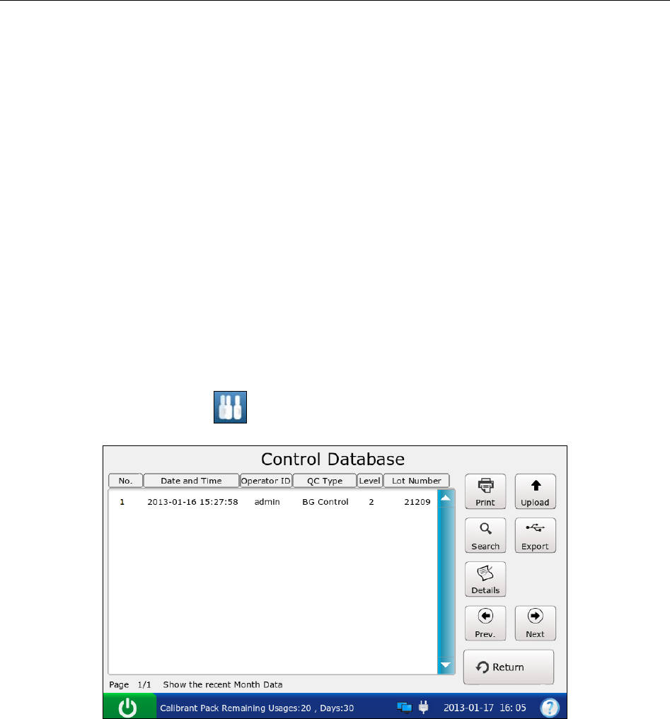
i15 Blood Gas and Chemistry Analysis System User Manual Quality Control (QC) Tests
- 80 -
6.1.3 Control Database
The control database displays control test data for the most recent month by default, and it can
hold up to 1000 data entries. The system displays 50 data entries on every page. Press Prev. and
Next to page through the screens of the displayed data entries. When 80% of the space is
occupied, the system will prompt you to export the stored data to a removable disk (such as a
USB drive). If data is not exported, the system will continue to save new data. When the database
is full, the system will always prompt you to export the stored data. If data is still not exported,
the system will automatically delete the oldest one to accommodate a new one. The following
operations can be performed in the control database: transmitting control test data to the Data
Management System (DMS) through WIFI or the network, exporting control test data to a
removable disk (such as a USB drive), viewing the details of control test data, searching for and
printing control test data, etc.
On the Database screen, press to get to the Control Database screen.
Figure 6-11 Control Database Screen
6.1.3.1 Searching for Control Test Data
1. On the Control Database screen, press Search.
2. Enter the search conditions, and press OK.
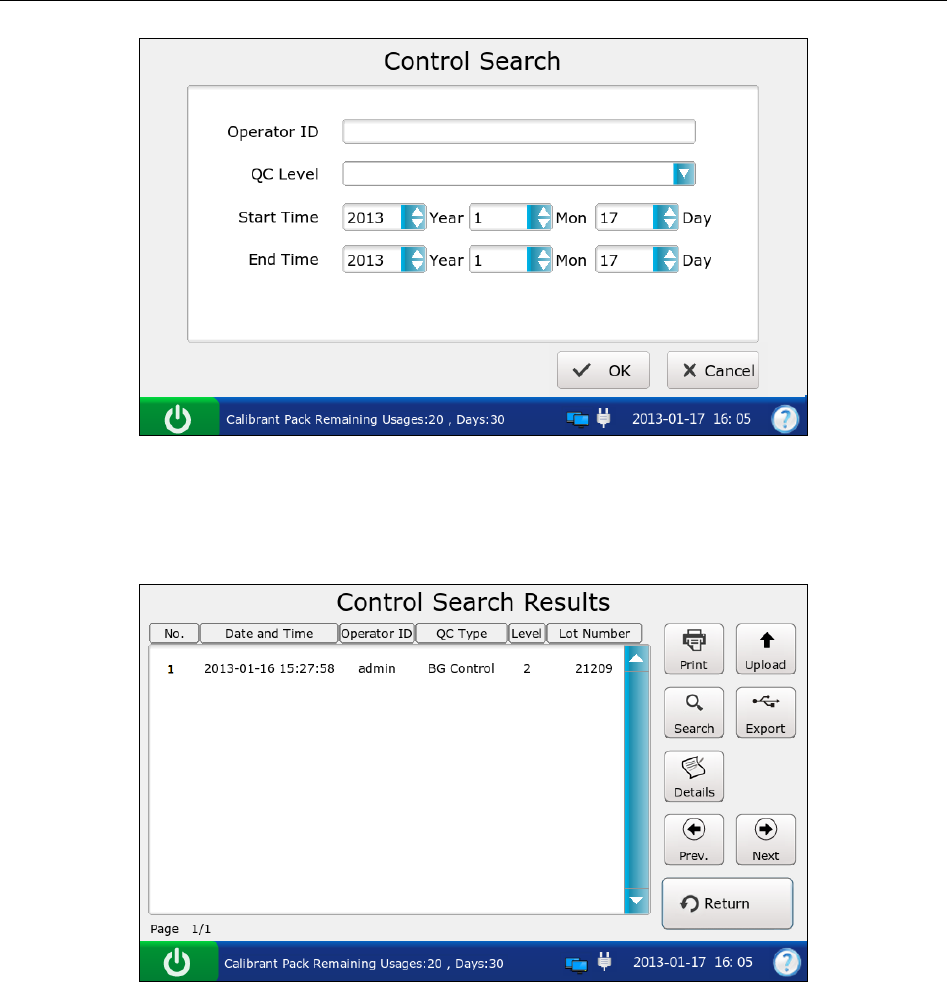
i15 Blood Gas and Chemistry Analysis System User Manual Quality Control (QC) Tests
- 81 -
Figure 6-12 Enter Search Conditions
3. The system automatically begins the search and displays the results.
Figure 6-13 Search Results
4. Press Return to go back to the Control Database screen.
6.1.3.2 Viewing Details of Control Test Data
1. Press the control test data you want to view.
2. Press Details. The system displays the details:
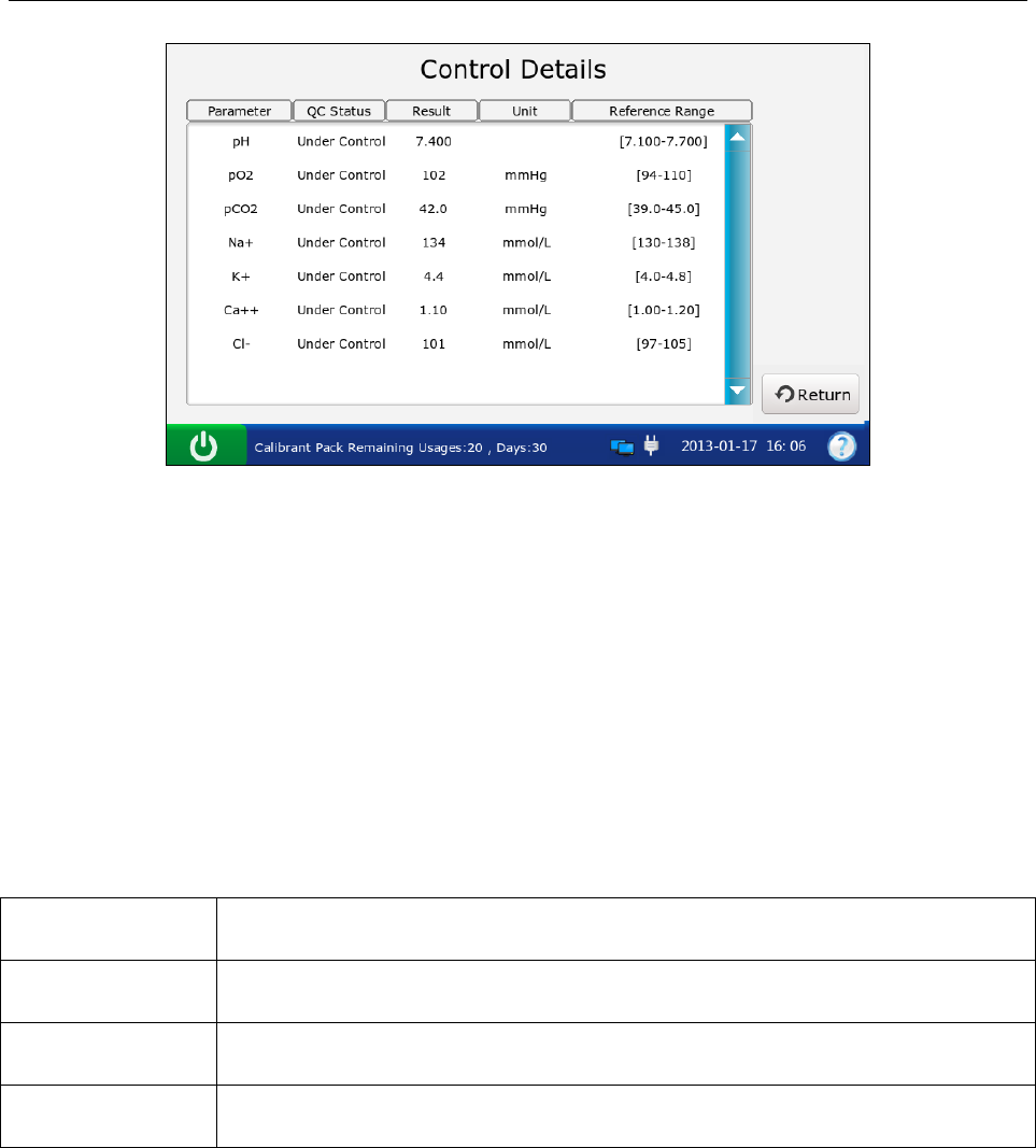
i15 Blood Gas and Chemistry Analysis System User Manual Quality Control (QC) Tests
- 82 -
Figure 6-14 Details of Control Test Results
3. View the details.
4. Press Return to go back to the Control Database screen.
6.1.3.3 Exporting/Uploading/Printing Control Test Data
1. Open the control database.
2. Select the desired control test data.
To Do this
Export Insert a removable disk into the analyzer, and then press Export.
Upload Press Upload.
Print Press Print.
NOTE:
If no control test data is selected before pressing Export/Upload/Print, all of the data
stored in the control database will be exported/uploaded/printed.
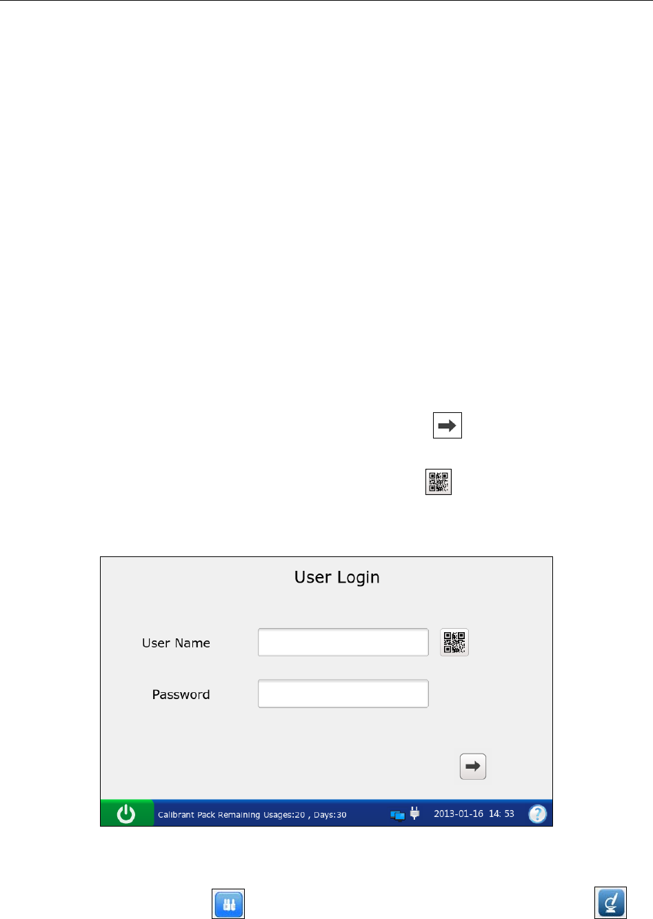
i15 Blood Gas and Chemistry Analysis System User Manual Quality Control (QC) Tests
- 83 -
6.2 Proficiency Test
Proficiency tests are also called external quality control tests. In proficiency tests, the analysis of
unknown samples from external quality control providers can reflect the accuracy of the system.
6.2.1 Procedures for Proficiency Test
Follow the directions below to perform a proficiency test:
1. Examine the package label of proficiency samples to ensure they have not expired.
2. Remove an ampoule from the box and equilibrate it to room temperature.
If oxygen is to be measured, the ampoule needs to stand at room temperature for 4 hours. If
not, the ampoule needs to stand at room temperature for only about 30 minutes.
3. Press the On/Off button on the left hand side of the analyzer to turn it on.
4. Enter the user name and password manually, and then press .
To enter the user name with the bar code scanner, press first, and then scan the user
name bar code.
Figure 6-15 Enter User Name and Password
5. On the Main screen, press to go to the Quality Control screen, and then press .
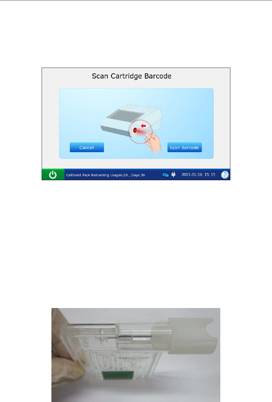
i15 Blood Gas and Chemistry Analysis System User Manual Quality Control (QC) Tests
- 84 -
6. Press Scan Barcode, and scan the bar code on a new cartridge foil pouch.
If the bar code is scanned successfully, the system will beep and the scanner will be
automatically turned off. If the scanned data is valid, the system will display the screen for
the next procedure. If the scanned data is invalid, a message will pop up to prompt you.
Figure 6-16 Scan Bar Code
7. Open the foil pouch and remove the cartridge from it.
NOTE:
Avoid tearing the bar code on the foil pouch.
For sample introduction with a capillary tube or an ampoule, please insert a capillary
adaptor/ampoule adaptor into the fillport after removing the cartridge.
When inserting an ampoule adaptor into the fillport of a test cartridge, make sure the
indent of the adaptor is on the upside as shown in the picture below:
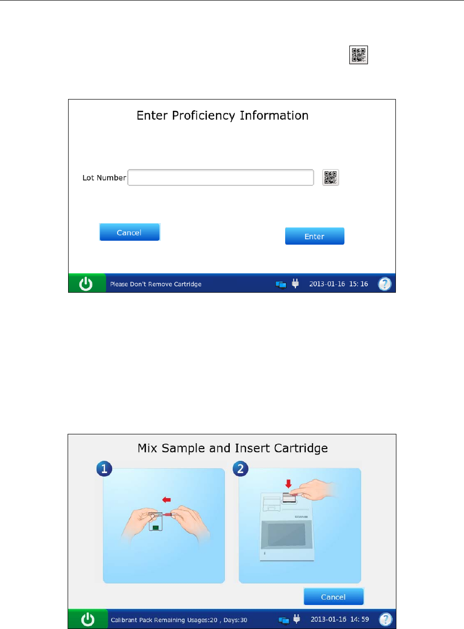
i15 Blood Gas and Chemistry Analysis System User Manual Quality Control (QC) Tests
- 85 -
8. Enter the lot number of the proficiency sample, and then press Enter.
To enter the lot number information with the bar code scanner, press first, and then scan
the bar code.
Figure 6-17 Enter Information
NOTE:
Only lot number information within 1-16 digits is acceptable.
9. Mix the proficiency sample completely by shaking the ampoule gently, and then tap the tip of
the ampoule carefully with your fingernail to remove any solution.
Figure 6-18 Mix Proficiency Sample and Insert Cartridge
NOTE:
Avoid heating the ampoule with your hands when shaking the ampoule.

i15 Blood Gas and Chemistry Analysis System User Manual Quality Control (QC) Tests
- 86 -
10. Open the ampoule by snapping off the top and immediately transfer proficiency solution by
slowly drawing an appropriate amount of solution with a syringe or capillary tube from the
bottom of the ampoule.
NOTE:
When using an ampoule, you need not transfer the proficiency solution. Insert the
ampoule into the adaptor after opening it, and directly go to step 12.
Take protective measures when opening the ampoule, such as using gloves, tissue,
etc.
11. Insert the syringe or capillary tube into the fillport of the cartridge.
NOTE:
When using a syringe, discard the first 2 drops of solution first, then remove the
needle from it, and finally insert it into the fillport.
When using a capillary tube, directly insert the capillary tube into the adaptor till the
tube reaches the interface between the adaptor and the cartridge.
To avoid inaccurate test results, make sure there are no bubbles in the sample. If
bubbles continually exist, use a new ampoule and syringe or capillary tube to collect
samples again.
12. Gently insert the cartridge into the cartridge port, and carefully press down to ensure that it
clicks into place.
For a valid cartridge, the indicator in the cartridge port will turn green, and the system will
automatically aspirate calibrant. For an invalid cartridge, the indicator will turn red, the
cartridge will be ejected and a message will pop up to prompt you.
NOTE:
The cartridge can not be removed from the analyzer until the measurement is
complete.
Never inject the sample. It will be aspirated automatically.
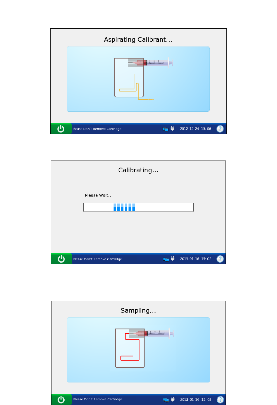
i15 Blood Gas and Chemistry Analysis System User Manual Quality Control (QC) Tests
- 87 -
13. The system automatically aspirates calibrant.
Figure 6-19 Aspirating Calibrant…
14. The system automatically performs calibration.
Figure 6-20 Calibration in Progress
15. The system automatically aspirates samples when calibration is complete.
Figure 6-21 Sampling…
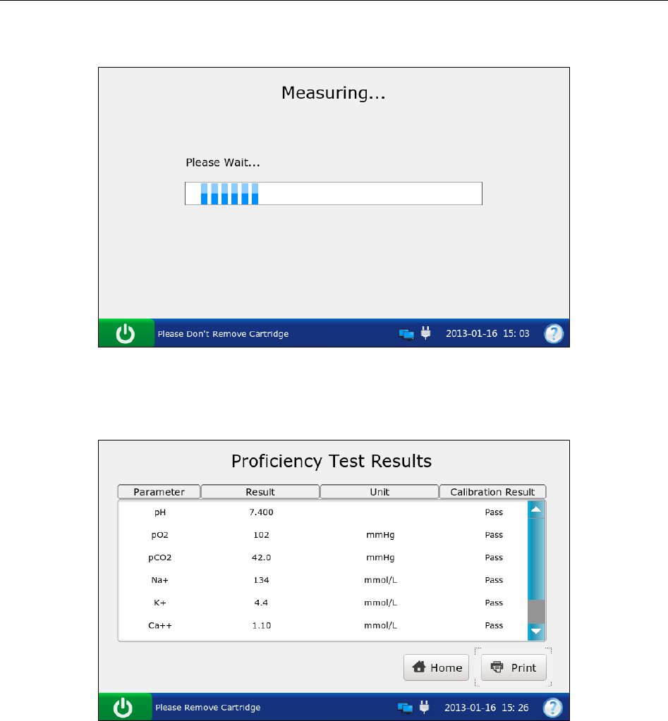
i15 Blood Gas and Chemistry Analysis System User Manual Quality Control (QC) Tests
- 88 -
16. The system automatically analyzes the sample upon the completion of sampling.
Figure 6-22 Measurement in Progress
17. The system automatically displays the test results upon the completion of the test.
Figure 6-23 Proficiency Test Results
18. View the results.
19. Remove the test cartridge from the system.
20. Press Print to print the results.
21. Press Home to return to the Main screen.

i15 Blood Gas and Chemistry Analysis System User Manual Quality Control (QC) Tests
- 89 -
Here is an example of a proficiency test report.
Proficiency Test Report
EDAN i15
System ID 201303200023
Report Type Proficiency Test Report
Print Time 2012-03-20 15:20:00
Test Time 2012-03-20 15:10:00
Operator ID 55555
Lot Number 21209
Calibration Results
pH Pass
p
CO2 Pass
p
O2 Pass
…
Proficiency Test Results
pH 7.4
p
CO2 40 mmHg
p
O2 90 mmHg
Na+ 140 mmol/L
K+ 4.0 mmol/L
Ca++ 1.2 mmol/L
Cl- 101 mmol/L
Glu 4.1 mmol/L
Lac 0.8 mmol/L
Hct 40 %
Cre 0.7 mg/dL
BUN 23 mmol/L
6.2.2 Proficiency Database
The proficiency database displays all the proficiency test data by default, and it can store up to
1000 data entries. The system displays 50 data entries on every page. Press Prev. and Next to
page through the screens of the displayed data entries. The following operations can be
performed in the proficiency database: transmitting proficiency test data to the Data Management
System (DMS) through WIFI or the network, exporting proficiency test data to a removable disk
(such as a USB drive), viewing the details of proficiency test data, searching for and printing
proficiency test data, etc.
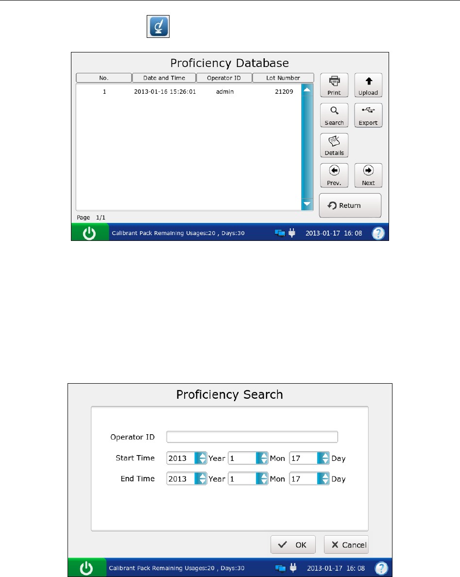
i15 Blood Gas and Chemistry Analysis System User Manual Quality Control (QC) Tests
- 90 -
On the Database screen, press to get access to the Proficiency Database screen.
Figure 6-24 Proficiency Database Screen
6.2.2.1 Searching for Proficiency Test Data
1. On the Proficiency Database screen, press Search.
2. Enter the search conditions, and press OK.
Figure 6-25 Enter Search Conditions
3. The system automatically begins the search and displays the results.
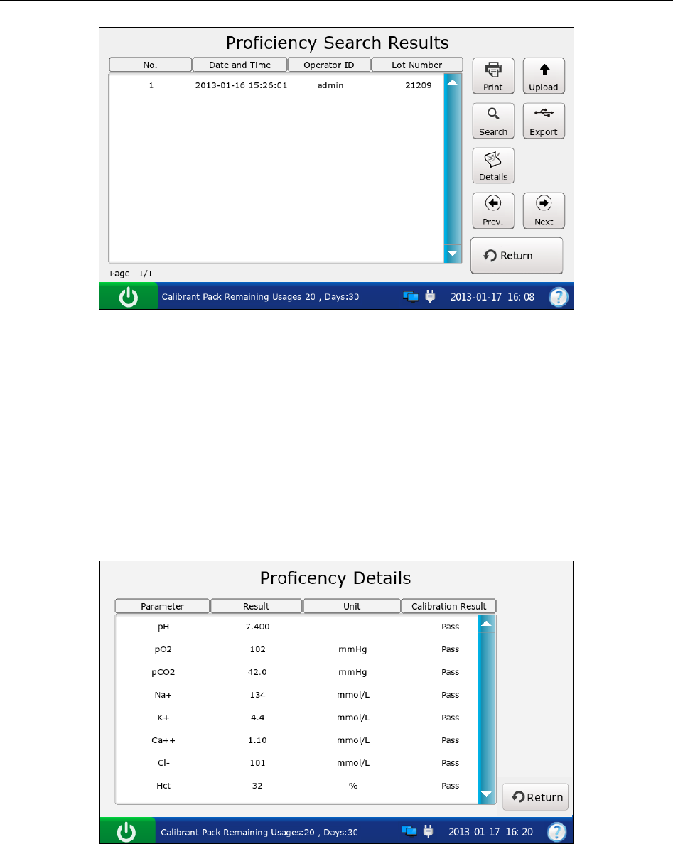
i15 Blood Gas and Chemistry Analysis System User Manual Quality Control (QC) Tests
- 91 -
Figure 6-26 Search Results
4. Press Return to go back to the Proficiency Database screen.
6.2.2.2 Viewing Details of Proficiency Test Data
1. Press the proficiency test data you want to view.
2. Press Details. The system displays the details:
Figure 6-27 Details of Proficiency Test Results
3. View the details.
4. Press Return to go back to the Proficiency Database screen.
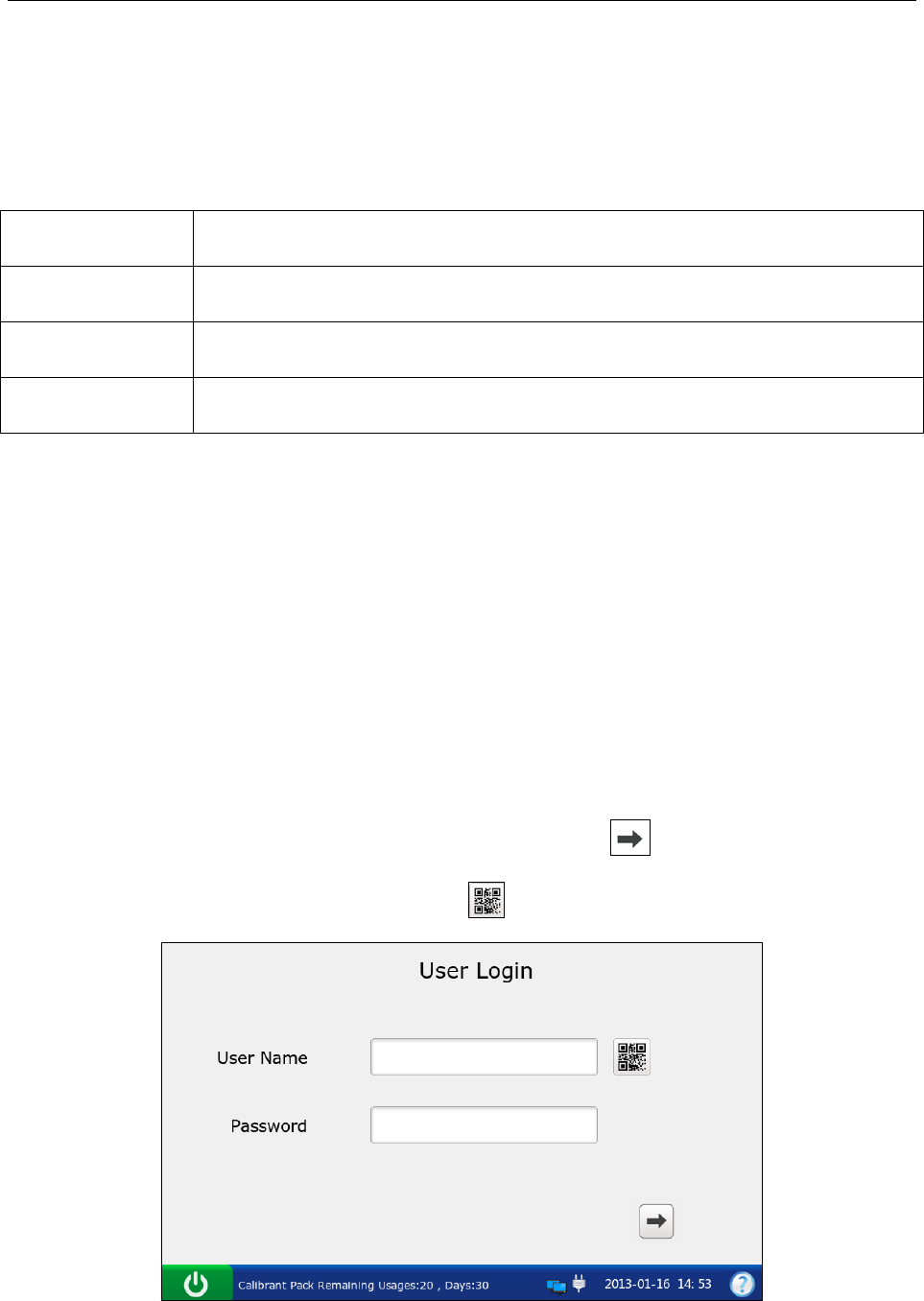
i15 Blood Gas and Chemistry Analysis System User Manual Quality Control (QC) Tests
- 92 -
6.2.2.3 Exporting/Uploading/Printing Proficiency Test Data
1. Open the proficiency database.
2. Select the desired proficiency test data.
To Do this
Export Insert a removable disk into the analyzer, and then press Export.
Upload Press Upload.
Print Press Print.
NOTE:
If no proficiency test data is selected before pressing Export/Upload/Print, all of the data
stored in the proficiency database will be exported/uploaded/printed.
6.3 Simulator Test
6.3.1 Procedures for External Simulator Test
Follow the procedures below to perform an external simulator test:
1. Press the On/Off button on the left hand side of the analyzer to turn it on.
2. Enter the user name and password manually, and then press .
To scan the bar code of the user name, press first, and then scan the bar code.
Figure 6-28 Enter User Name and Password
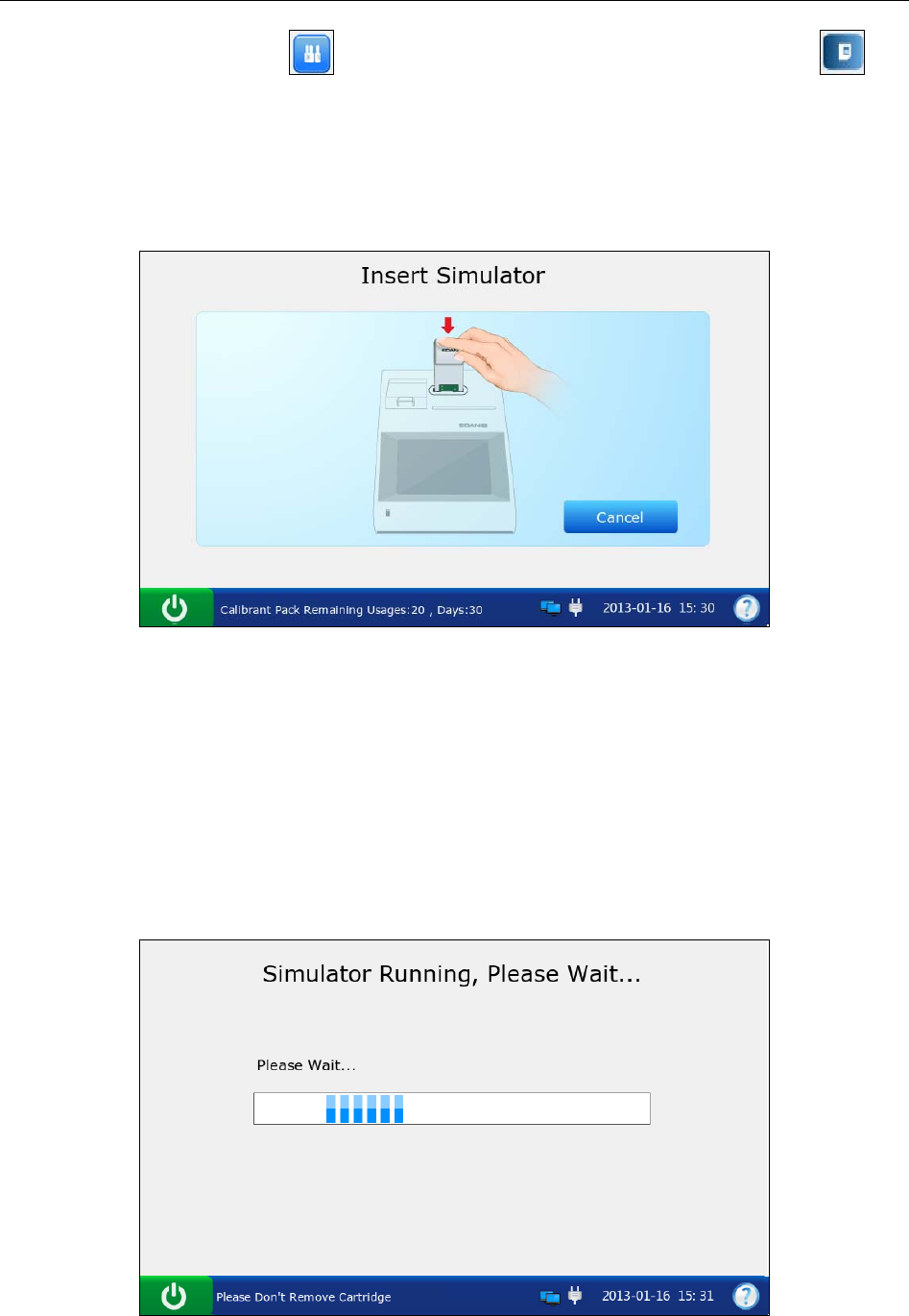
i15 Blood Gas and Chemistry Analysis System User Manual Quality Control (QC) Tests
- 93 -
3. On the Main screen, press to go to the Quality Control screen, and then press .
4. Gently insert the external electronic simulator into the cartridge port, and press down to
ensure it clicks into place. If the electronic simulator is inserted properly, the system will
automatically perform a simulator test.
Figure 6-29 Insert External Simulator
NOTE:
Avoid touching the contact pads.
Never touch the simulator after inserting it into the system.
5. The system automatically starts to perform an external simulator test.
Figure 6-30 Measurement in Progress
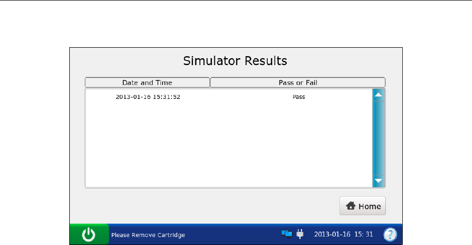
i15 Blood Gas and Chemistry Analysis System User Manual Quality Control (QC) Tests
- 94 -
6. The system automatically displays the test result upon the completion of the test.
Figure 6-31 External Simulator Test Result
7. View the result.
NOTE:
Upon the completion of the test, the message “Please Remove Cartridge” will be
displayed on the status bar at the bottom of the screen, and the simulator will be
ejected.
If the system passes the external simulator test, it can be used to analyze samples.
If the system fails the external simulator test, perform the test again or try another
simulator. If it passes the test, it can be used to analyze samples. If it fails again,
contact EDAN or its authorized distributors for assistance.
8. Press Home to go to the Main screen.
9. Remove the external simulator from the system, and put it back.
NOTE:
Never remove the external simulator until the test is complete.
6.3.2 Simulator Database
The simulator database displays all of the simulator test data by default, and it can store up to
2000 data entries. The system displays 50 data entries on every page. Press Prev. and Next to
page through the screens of the displayed data entries. When 80% of the space is occupied, the
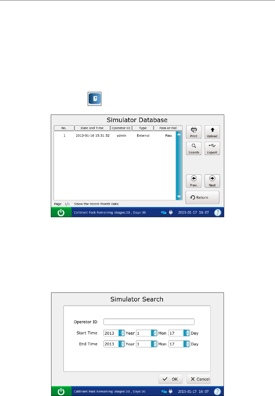
i15 Blood Gas and Chemistry Analysis System User Manual Quality Control (QC) Tests
- 95 -
system will prompt you to export the stored data to a removable disk (such as a USB drive). If
data is not exported, the system will continue to save new data. When the database is full, the
system will always prompt you to export data. If data is still not exported, the system will
automatically delete the oldest one to accommodate a new one. The following operations can be
performed in the simulator database: transmitting simulator test data to the Data Management
System (DMS) through WIFI or the network, exporting simulator test data to a removable disk
(such as a USB drive), searching for and printing simulator test data, etc.
On the Database screen, press to get access to the Simulator Database screen.
Figure 6-32 Simulator Database Screen
6.3.2.1 Searching for Simulator Test Data
1. On the Simulator Database screen, press Search.
2. Enter the search conditions, and press OK.
Figure 6-33 Enter Search Conditions
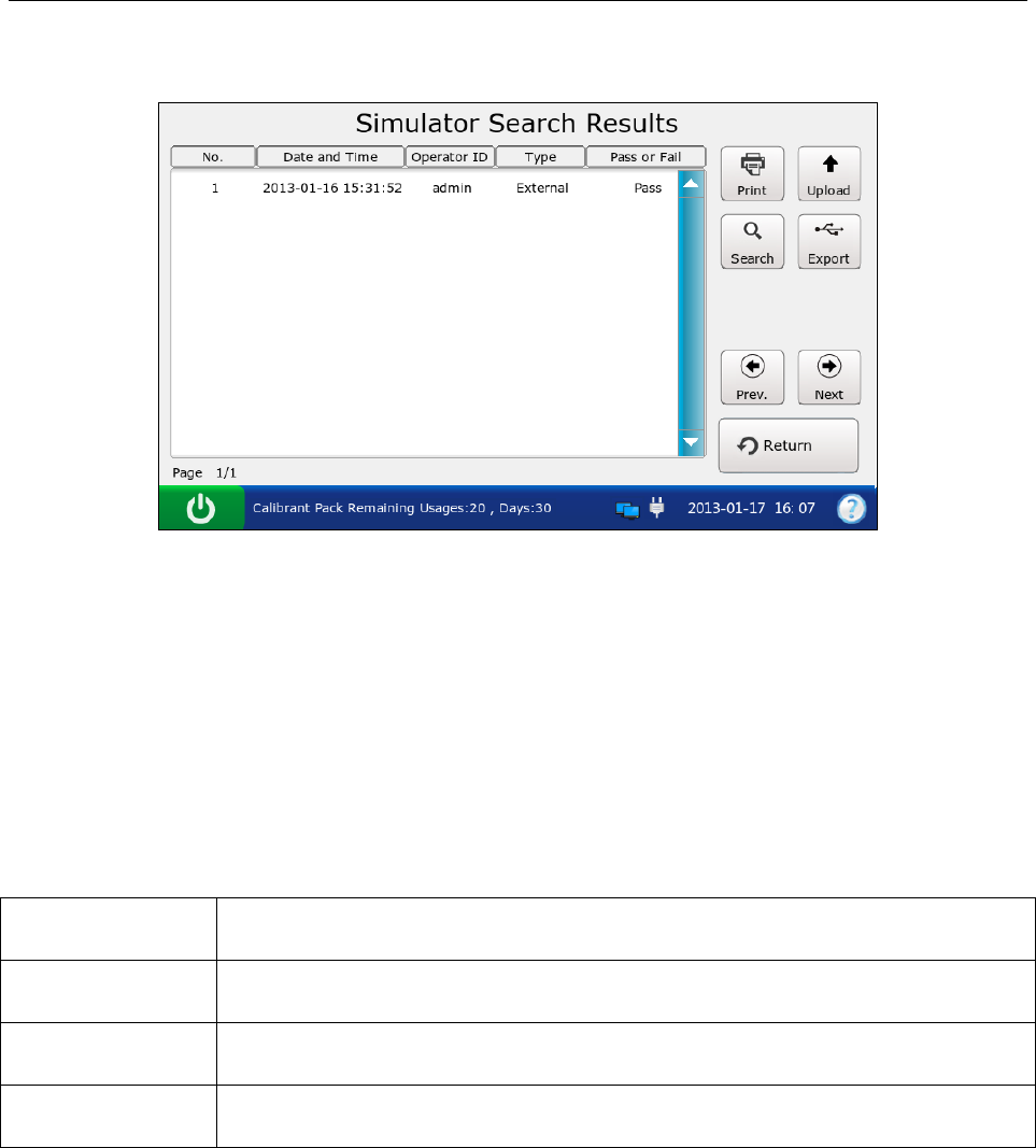
i15 Blood Gas and Chemistry Analysis System User Manual Quality Control (QC) Tests
- 96 -
3. The system automatically begins the search and displays the results.
Figure 6-34 Search Results
4. Press Return to go back to the Simulator Database screen.
6.3.2.2 Exporting/Uploading/Printing Simulator Test Data
1. Open the simulator test database.
2. Select the desired simulator test data.
To Do this
Export Insert a removable disk into the analyzer, and then press Export.
Upload Press Upload.
Print Press Print.
NOTE:
If no simulator test data is selected before pressing Export/Upload/Print, all of the data
stored in the simulator database will be exported/uploaded/printed.

i15 Blood Gas and Chemistry Analysis System User Manual Quality Control (QC) Tests
- 97 -
Here are examples of simulator test reports:
External Simulator Test Report
EDAN i15
System ID 201303200023
Report Type External Simulator Test Report
Print Time 2012-03-20 15:20:00
Test Time 2012-03-20 15:20:00
Operator ID admin
Result Pass
Internal Simulator Test Report
EDAN i15
System ID 201303200023
Report Type Internal Simulator Test Report
Print Time 2012-03-20 15:20:00
Test Time 2012-03-20 15:20:00
Operator ID admin
Result Pass
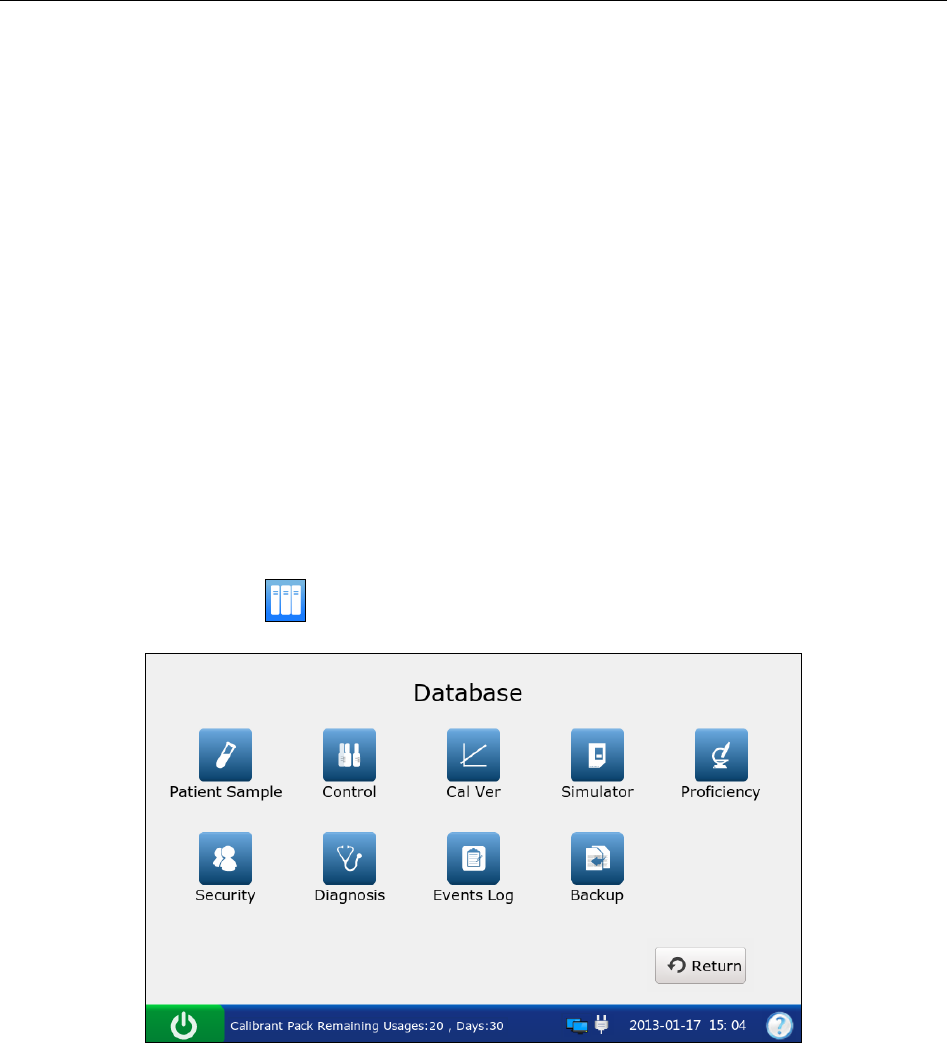
i15 Blood Gas and Chemistry Analysis System User Manual Data Management
- 98 -
Chapter 7 Data Management
7.1 Introduction
The system has powerful data management ability. It can logically manage the results for
different tests and transmit them to the DMS.
There are two ways of transmitting data:
With a removable disk such as a USB drive
Through LAN/WLAN
NOTE:
The transmitted data can only be opened by the DMS.
On the Main screen, press to get access to the Database screen.
Figure 7-1 Database Screen
7.2 Databases
The following databases have been described in the previous chapters: Patient Sample Database,
Control Database, Proficiency Database, Simulator Database. In this part, the databases below
will be described: Security Database, Diagnosis Database, Events Log Database and Backup.
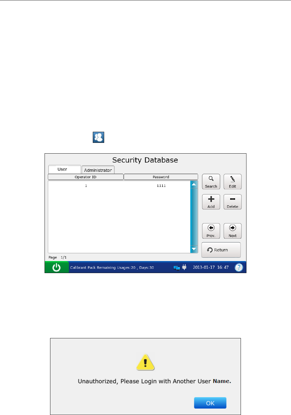
i15 Blood Gas and Chemistry Analysis System User Manual Data Management
- 99 -
7.2.1 Security Database
NOTE:
Only administrators can get access to the security database.
The security database displays all the security data by default, and it can store up to 100 data
entries. The system displays 50 data entries on every page. Press Prev. and Next to page through
the screens of the displayed data entries. The following operations can be performed in the
security database: deleting security data, searching for operators, adding and editing security data,
etc.
On the Database screen, press to get access to the Security Database screen.
Figure 7-2 Security Database Screen
Operators are divided into four levels according to their access rights: operators, administrators,
service engineers and engineers from the manufacturer. If an operator cannot access a function,
the following message will appear:
Figure 7-3 No Access Rights
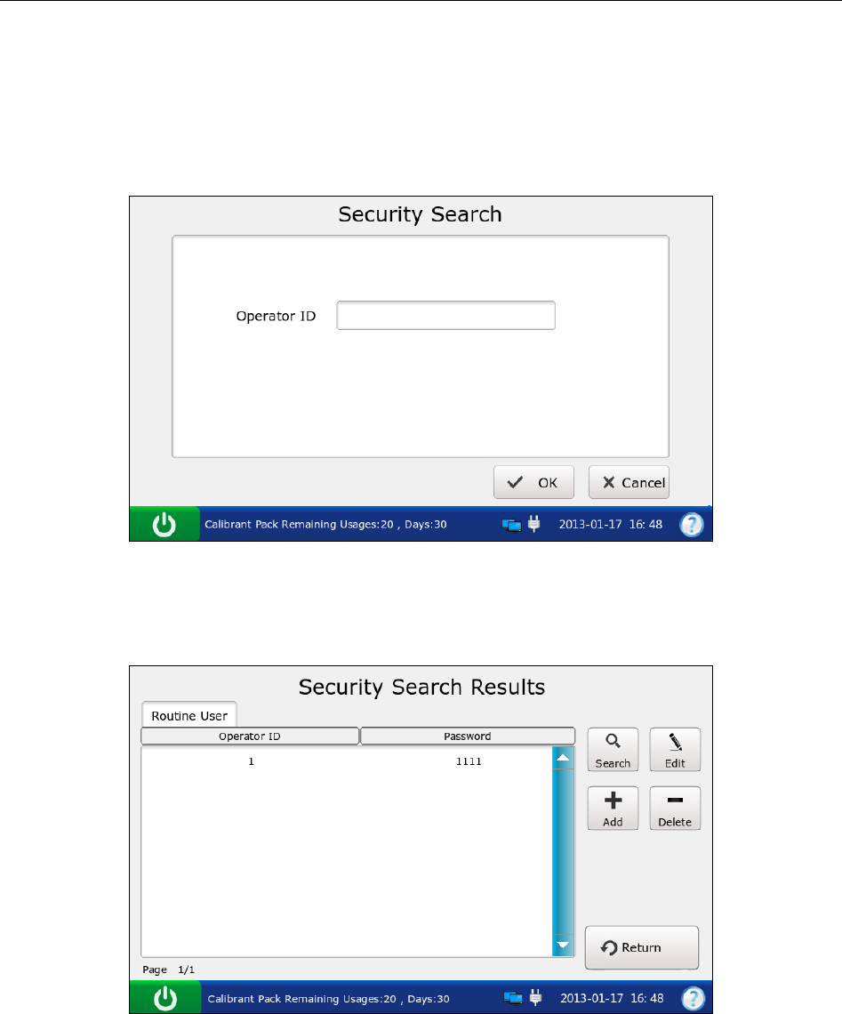
i15 Blood Gas and Chemistry Analysis System User Manual Data Management
- 100 -
7.2.1.1 Searching for an Operator
1. On the Security Database screen, press Search.
2. Enter the operator ID, and press OK.
Figure 7-4 Enter Search Conditions
3. The system automatically begins the search and displays the results.
Figure 7-5 Search Results
4. Press Return to go back to the Security Database screen.
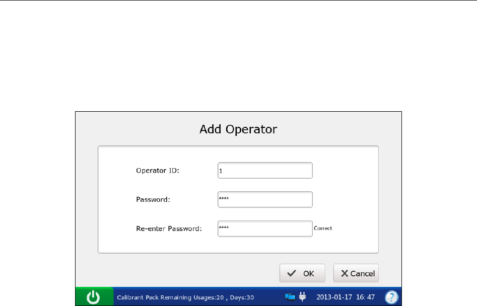
i15 Blood Gas and Chemistry Analysis System User Manual Data Management
- 101 -
7.2.1.2 Adding an Operator
1. On the Security Database screen, press Add.
2. Enter the operator ID, password and re-enter the same password.
Figure 7-6 Add Operator
3. Press OK to save the changes, and press OK in the pop up dialog box. The system will
go to the Security Database screen.
NOTE:
The operator ID is case sensitive, and should be 1 - 16 characters long (including
both letters and numbers). "admin/demo/service/edan", or upper and lower case
combinations of these words are not permitted.
The password is case sensitive, and should be 4 - 16 characters long (including both
letters and numbers).
7.2.1.3 Changing Operator Password
1. Select the operator data you want to edit.
2. Press Edit.
3. Enter the password, and re-enter the same password.
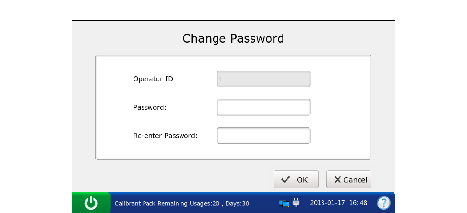
i15 Blood Gas and Chemistry Analysis System User Manual Data Management
- 102 -
Figure 7-7 Change Operator Password
4. Press OK to save the changes, and press OK in the pop up dialog box. The system will
go to the Security Database screen.
NOTE:
The password is case sensitive, and should be 4 - 16 characters long (including both
letters and numbers).
7.2.1.4 Deleting Security Data
1. Select the desired security data.
2. Press Delete, and press OK in the pop up message.
NOTE:
If no security data is selected before pressing Delete, all of the data stored in the security
database will be deleted.
7.2.1.5 Changing System Password
1. Press Administrator on the Security Database screen.
2. Press Edit.
3. Enter the current system password, enter the new system password and re-enter the same
password.
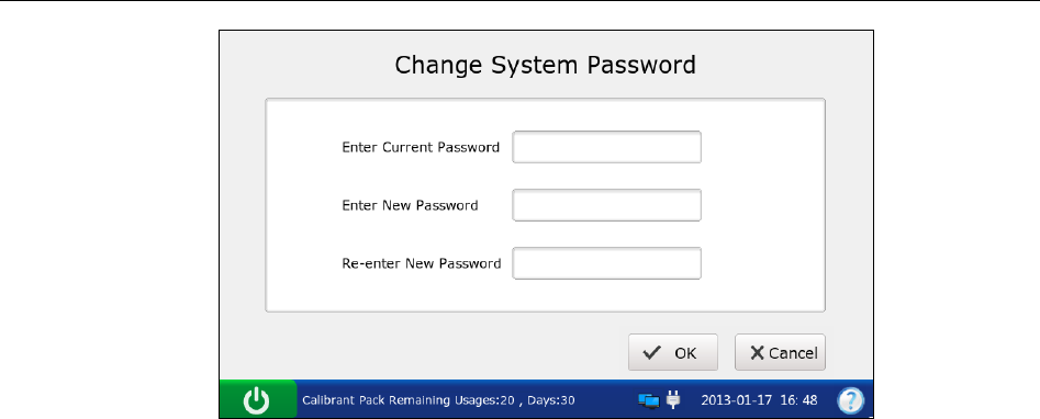
i15 Blood Gas and Chemistry Analysis System User Manual Data Management
- 103 -
Figure 7-8 Change System Password
4. Press OK to accept the changes, and press OK in the pop up dialog box. The system will
go to the User Login screen.
NOTE:
The default factory system password is 123456.
Only administrators can change the system password (Even engineers from the
manufacturer can not change it, although they can retrieve the password to the
default factory setting).
7.2.2 Diagnosis Database
The diagnosis database displays diagnosis data for the most recent month by default, and it can
store up to 10000 data entries. The following operations can be performed in the diagnosis
database: exporting diagnosis data to a removable disk (such as a USB drive), viewing the details
of diagnosis data, searching for and printing diagnosis data, etc.
NOTE:
Only service engineers and engineers from the manufacturer can get access to the
diagnosis database.
7.2.3 Events Log Database
The events log database records the following information: User Login and Logout, changing
time and date, changing slopes and offsets, changing patient information, deleting data stored in
databases, replacing a calibrant fluid pack. It can store up to 10000 data entries. The system
displays 50 data entries on every page. Press Prev. and Next to page through the screens of the
displayed data entries. You can export, search for and print the events with the events log
database.
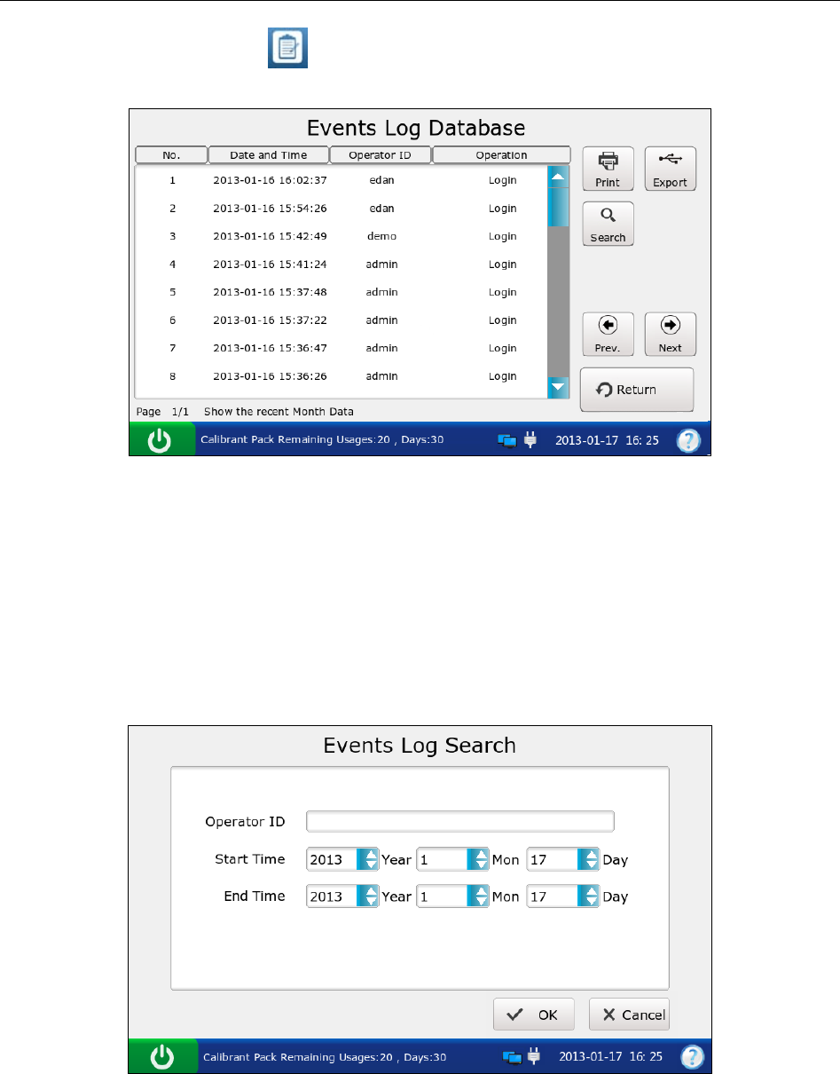
i15 Blood Gas and Chemistry Analysis System User Manual Data Management
- 104 -
On the Database screen, press to get access to the Events Log Database screen.
Figure 7-9 Events Log Database Screen
7.2.3.1 Searching for Events Data
1. On the Events Log Database screen, press Search.
2. Enter the search conditions, and press OK.
Figure 7-10 Enter Search Conditions
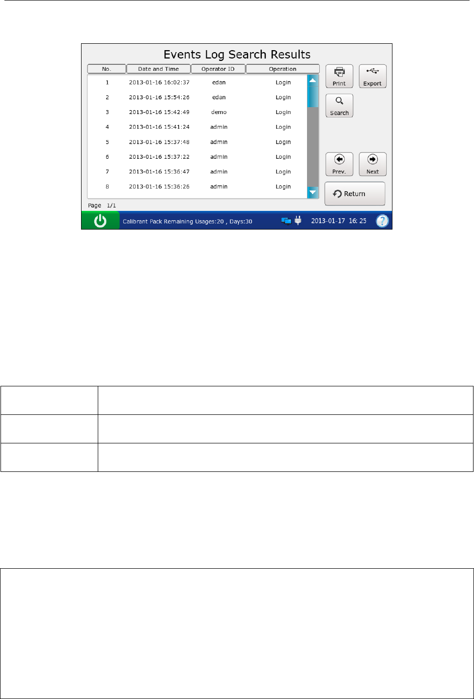
i15 Blood Gas and Chemistry Analysis System User Manual Data Management
- 105 -
3. The system automatically begins the search and displays the results.
Figure 7-11 Search Results
4. Press Return to go back to the Events Log Database screen.
7.2.3.2 Exporting/Printing Events Data
1. Open the events log database.
2. Select the desired event data.
To Do this
Export Insert a removable disk into the analyzer, and then press Export.
Print Press Print.
NOTE:
If no event data is selected before pressing Export/Print, all of the data stored in the
events log database will be exported/printed.
Here is an example of an event log report:
EDAN i15
System ID 201303200023
Print Time 2012-03-20 15:20:00
Log Time 2012-03-20 15:20:00
Report Type Events Log Report
Operator ID 1111
Operation Change date and time
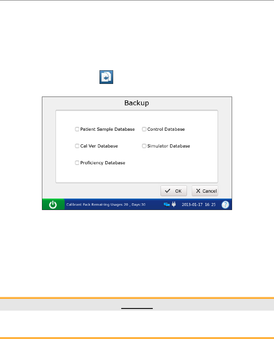
i15 Blood Gas and Chemistry Analysis System User Manual Data Management
- 106 -
7.2.4 Backup
With this function, all of the stored data in the following databases can be backed up: Patient
Sample Database, Control Database, Proficiency Database and Simulator Database.
Follow the steps below to backup data:
1. On the Database screen, press to access the Backup screen.
Figure 7-12 Backup Screen
2. Select the database you want to backup. √ indicates the database is selected.
3. Press OK, and press OK in the pop up dialog box, the system will backup all of the data
stored in the database.
4. Press OK in the pop up dialog box to delete all of the data in the backup database.
CAUTION
Deleting data in the backup database is permanent. Deleted data can not be recovered
after deletion.

i15 Blood Gas and Chemistry Analysis System User Manual Online Update
- 107 -
Chapter 8 Online Update
8.1 Introduction
Online update refers to analog board software update.
The system can download the latest version of the update program from the network and
automatically install it.
Only engineers from the manufacturer can perform this action.
8.2 Procedures for Online Update
NOTE:
Avoid interruption of the power supply during the update process.
1. Press Setup Diagnostics Analog Update.
2. The system will automatically download the latest version of the update program and
perform updating.
3. Press OK when the update is complete. If the update fails, the system will prompt you.

i15 Blood Gas and Chemistry Analysis System User Manual Troubleshooting
- 108 -
Chapter 9 Troubleshooting
The following table lists some problems you may encounter to assist in troubleshooting.
Table 9-1 Troubleshooting Examples
Item Problem Solution
1 A test cartridge will
not be ejected
automatically when a test is complete.
If the system is running smoothly, remove
the test cartridge ejector cap, pull the middle
hole with a pointed object, and remove the
test cartridge from the system.
2 A
test cartridge is inserted into the system
prior to a test.
Remove the test cartridge ejector cap, pull
the middle hole with a pointed object, and
remove the test cartridge from the system.
3 A simulator will not be ejected automatically
when a simulator test is complete.
Remove the test cartridge ejector cap, pull
the middle hole with a pointed object, and
remove the simulator from the system.
4 A test cartridge can not be removed because
of power interruption during operation.
C
onnect the system to AC power, and turn
on the system. After about 1 minute, the test
cartridge will be ejected automatically. If it
is not ejected automatically, remove the test
cartridge eje
ctor cap, pull the middle hole
with a pointed
object, and remove the test
cartridge from the system.
5
A test cartridge can not be ejected because
the system malfunctions, for example, the
system is dead.
Reboot the system. A
fter about 1 minute,
the test c
artridge will be ejected
automatically. I
f it is not ejected
automatically, remove the test cartridge
ejector cap, pull the middle hole with a
pointed object, and remove the test cartridge
from the system.
6 The prompt “Cartridge is not Qualified”
appears.
P
erform an electronic simulator test to
confirm that the system is working
smoothly. If the system passes the simulator
test, perform sample tests with new test
cartridges. If the problem continues after
several attempts, please contact EDAN or
its authorized distributors for assistance.
7 The prompt “POGO_PIN does Not Contact P
erform the test again with a new test
cartridge. I
f the prompt appears again,

i15 Blood Gas and Chemistry Analysis System User Manual Troubleshooting
- 109 -
Well” appears.
please contact EDAN or its authorized
distributors for assistance.
8 The prompt “Cartridge Expired” appears.
Verify that the current date is correct. If the
prompt appears again, check that the test
cartridge has not expired. If it has expired,
use a new test cartridge that has not expired.
9 The prompt “
Calibrant is Not Aspirated
Properly” appears.
P
erform the test again with a new test
cartridge. I
f the prompt appears again,
please contact EDAN or its authorized
distributors for assistance.
10 The prompt “Air is Not Aspirated Properly”
appears.
P
erform the test again with a new test
cartridge. I
f the prompt appears again,
please contact EDAN or its authorized
distributors for assistance.
11 The prompt “Sample Error. Maybe Clots are
Detected in Sample” appears.
Check that there are no clots in the blood
sample. If there are clots, discard it and
collect samples again.
12 The prompt “Insertion Error” appears.
V
erify that a simulator is inserted during a
simulator test and a test cartridge is inserted
during a sample test.
13
The prompt “
Calibrant Pack Expired,
Confirm Date Setup and Calibrant Pack’s
Expiration Date” appears.
Verify that the current date is correct. If the
prompt appears again, check that the
calibrant fluid pack has not expired. If it has
expired, replace the calibrant fluid pack
following the user manual instructions.
14 The prompt “Remaining Days: 0” appears.
T
he calibrant fluid pack has expired.
R
eplace the calibrant fluid pack following
the user manual instructions.
15 The prompt “Calibrant Pack Depleted”
appears.
The calibrant fluid pack has been depleted.
Replace the calibrant flu
id pack following
the user manual instructions.
16 The prompt “Current Date Error” appears.
The date is earlier than the manufacture date
of the calibrant fluid pack. Ensure that the
current date is correct.
17
The prompt “
Calibrant Pack Improper
Removal. Please Replace Calibrant Pack”
appears.
The calibrant fluid pack
is removed from
the system improperly. Replace the calibrant
fluid pack following the user manual
instructions.

i15 Blood Gas and Chemistry Analysis System User Manual Troubleshooting
- 110 -
18 The prompt “Barcode Cannot be Identified”
appears.
Ensure that the bar code is that of a calibrant
fluid pack.
19 The prompt “Calibrant Pack Can’t be Used,
Please Scan Again” appears.
Ensure that the bar code is that of a new
calibrant fluid pack and that the new
calibrant fluid pack has not expired.
20 The calibrant fluid pack chamber door can
not be opened.
Ensure that the calibrant fluid pack chamber
lock has been unlocked before opening the
door.
21 T
he system fails to scan the calibrant fluid
pack or test cartridge bar code.
C
heck that the calibrant fluid pack or test
cartridge bar code is not destroyed, and scan
it again.
22 Paper does not run from the paper tray.
O
pen the printer casing, adjust the paper
position carefully, and close the printer
casing. Press Print to print a record.
23 Paper-jam appears.
If a jam occurs for the first time, it might be
caused by an inappropriate placement of the
paper. In this case, open the paper casing,
remove the paper from
the paper tray,
remove the paper
with rumples, put the
paper in the paper tray again, adjust the
position of the paper carefully and close the
casing. If the problem continues, please
contact EDAN or its authorized distributors
for assistance.
24 The prompt “Paper?” appears.
Check whether there is paper in the printer
tray. I
f it has been depleted, load paper
again, and shut the printer casing. I
f the
problem continues, please contact EDAN or
its authorized distributors for assistance.
25 T
here is no sound after you successfully
press the touch screen. Check the volume setup.
26 T
he system can not be connected to a
network through WIFI.
E
nsure that the intensity of the network
signal is strong and that the network setup is
correct.
27 T
he system can not communicate with the
DMS.
Ensure that the network or WIFI is
successfully connected, and that the IP
address of the DMS is correct.

i15 Blood Gas and Chemistry Analysis System User Manual Troubleshooting
- 111 -
28 Fluids have been spilled on the screen. Clean and disinfect the screen following the
user manual instructions.
29 The USB scanner does not work smoothly.
Check the scanner type. I
f it is the type
recommended by EDAN, remove the
scanner from the system, and insert it again.
Set the scanner, and scan a bar code again.
30 Forget the user name or password.
F
or an operator, contact the administrator
for assistance. For an administrator, contact
EDAN or its authorized distributors for
assistance.
31 The lithium battery can not be charged.
Install the lithium battery following the user
manual instructions. Connect the system to
AC power. T
he system will be charged
automatically. If it still can not be charged,
please contact EDAN or its authorized
distributors for assistance.
32 There are fluids flowing from the bottom of
the analyzer.
M
ove the analyzer horizontally, and clear
the fluids. Remove the calibrant fluid pack
from the analyzer and check whether it is
damaged. I
f it is not damaged, perform a
simulator test and a control test to ensure the
proper performance of the system.
33 The prompt “
Ambient Temperature Out of
Range” appears.
C
heck that the ambient temperature is
within 10 - 31°C, and that the air vents are
not obstructed. Reboot the system. I
f the
problem continues, please contact EDAN or
its authorized distributors for assistance.
34 The prompt “Heating Abnormally” appears.
Please contact EDAN or its authorized
distributors for assistance.
35 The prompt “Abnormal Cam Location”
appears.
Please contact EDAN or i
ts authorized
distributors for assistance.
36 The date setup can not be saved after you
shut down the system.
P
lease contact EDAN or its authorized
distributors for assistance.
37 The system makes abnormal sounds. P
lease contact EDAN or its authorized
distributors for assistance.

i15 Blood Gas and Chemistry Analysis System User Manual Cleaning, Care and Maintenance
- 112 -
Chapter 10 Cleaning, Care and Maintenance
The system needs little care and maintenance. Clean and maintain it periodically to ensure its
optimum performance.
10.1 Cleaning and Disinfecting the Analyzer
Follow proper safety procedures and take protective measures such as wearing approved
gloves when cleaning and disinfecting the system.
NOTE:
Follow the instructions in this manual when cleaning and disinfecting the system.
Inside the test cartridge port should never be cleaned.
A test cartridge and a calibrant fluid pack should never be cleaned.
10.1.1 Cleaning and Disinfecting the Exterior Surfaces
Clean and disinfect the exterior surfaces to remove dust, splatters, blood, etc. Policies regarding
the cleaning and disinfecting intervals are at the discretion of your individual institution.
Following the procedures below to clean and disinfect the exterior surfaces:
1. Turn off the analyzer.
2. Disconnect the power cord and the power adaptor.
Disconnect the connecting cables if the system is connected to other pieces of equipment.
3. Dampen a lint-free cloth with 0.5% sodium hypochlorite solution.
NOTE:
The cloth should be wet but not dripping.
4. Clean the exterior surfaces with the wet cloth.
5. Clean the surfaces with the wet cloth to disinfect them after the surfaces are completely dry.
NOTE:
Clean the surfaces prior to disinfecting them.
Make sure the surfaces are thoroughly dry before disinfecting them.
6. When the surfaces are thoroughly dry, reconnect the power cord, power adaptor and other
connecting cables.
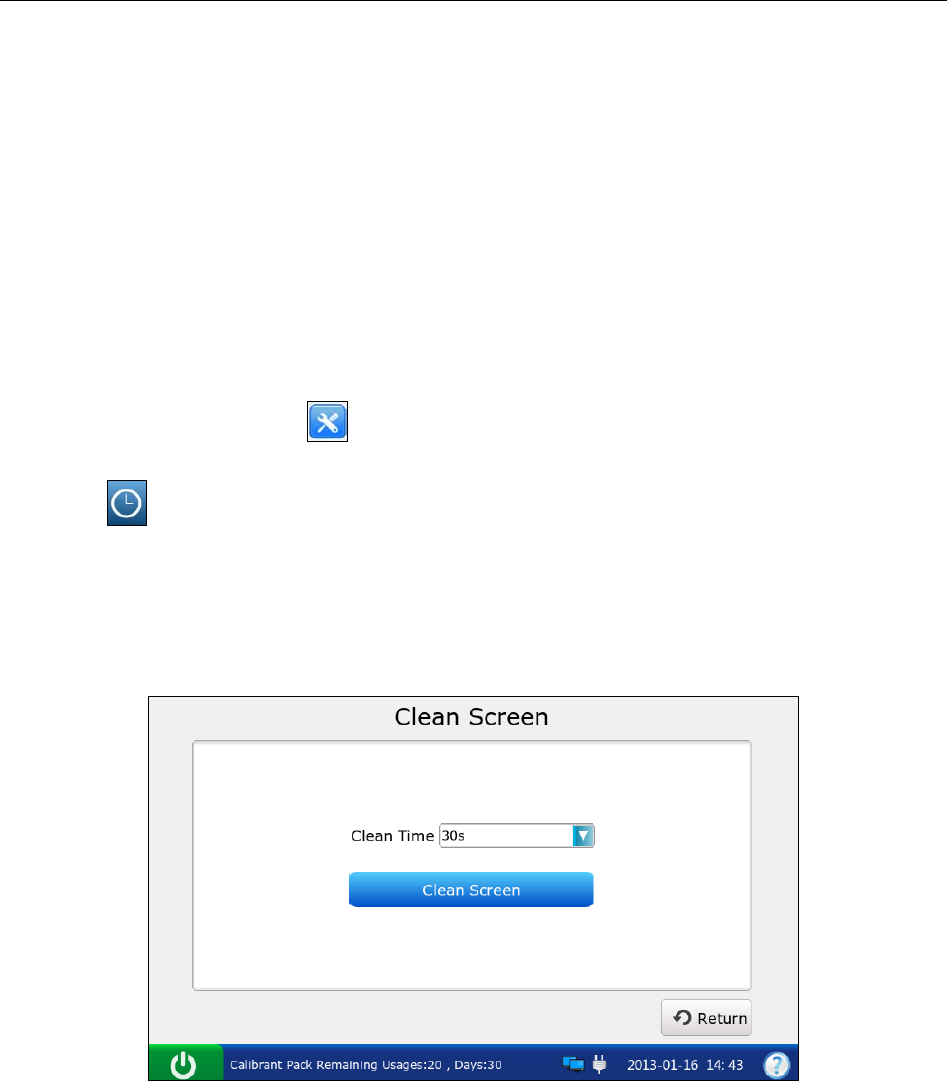
i15 Blood Gas and Chemistry Analysis System User Manual Cleaning, Care and Maintenance
- 113 -
10.1.2 Cleaning and Disinfecting the Screen
Clean and disinfect the screen to remove dust, splatters, blood, etc. Policies regarding the
cleaning and disinfecting intervals are at the discretion of your individual institution. Follow the
steps below to clean and disinfect the screen:
1. Dampen a lint-free cloth with 0.5% sodium hypochlorite solution.
NOTE:
The cloth should be wet but not dripping.
2. On the Main screen, press to go to the Setup screen.
3. Press on the System Setup screen.
4. Select the desired time period during which the system will have no response when you
touch the screen. There are four options: 30 seconds, 1 minute, 2 minutes and 5 minutes. The
default is 30 seconds.
Figure 10-1 Select Clean Time
5. Press Clean Screen. The system will display the screen below:
i15 Blood Gas and Chemistry Analysis System User Manual Cleaning, Care and Maintenance
- 114 -
Figure 10-2 Remaining Time
6. Clean the screen with the lint-free cloth.
7. Repeat steps 4-6 to disinfect the screen with the lint-free cloth after the screen is thoroughly
dry.
NOTE:
Clean the screen prior to disinfecting it.
Make sure that the screen is thoroughly dry before disinfecting it.
8. Press Return twice to return to the Main screen.
10.1.3 Cleaning the Printer Head
Dirty and soiled thermal printer heads will decrease the printing definition, so printer heads
should be cleaned at least once a month.
Open the printer casing and remove the printer paper. Clean the printer head gently with a clean
soft cloth dampened in 75% alcohol. For stubborn stains, soak the stain with a little alcohol first
and wipe it off with a clean soft cloth. After air drying, load the printer paper and shut the printer
casing.
1. Prevent the detergent from seeping into the system while cleaning. Do not immerse
the analyzer in liquid under any circumstances.
CAUTION
2. Do not clean the system with abrasive fabric.

i15 Blood Gas and Chemistry Analysis System User Manual Cleaning, Care and Maintenance
- 115 -
10.2 Care and Maintenance
10.2.1 Recharging and Replacement of Battery
Capacity Identification
Current capacity of the rechargeable battery can be identified according to the battery
symbol on the status bar at the bottom of the LCD screen:
: Full capacity.
: Capacity is not full.
: Capacity is limited, and recharging should be taken into account.
: Capacity is low, the battery should be recharged soon.
: Capacity is empty. The battery should be recharged immediately.
NOTE:
If the system is powered only by AC power, the symbol for the adaptor will
appear on the status bar at the bottom of the screen.
If the analyzer is powered only by the battery, one of the symbols above will appear
on the status bar at the bottom of the screen.
If the analyzer is powered by both the battery and AC power, and the battery is not
being charged, the symbol will appear on the status bar at the bottom of the
screen.
Recharging
The analyzer is equipped with a recharge control circuit together with a rechargeable lithium
battery. When the analyzer is connected to the mains supply, the battery will be recharged
automatically. Because of the capacity consumption during storage and transport, the battery
capacity will not be full when it is used for the first time. Battery recharging should be
considered before the first use.

i15 Blood Gas and Chemistry Analysis System User Manual Cleaning, Care and Maintenance
- 116 -
NOTE:
If the battery has not been used for more than two months, it should be recharged before
use.
Replacement
When the useful life of the battery is over, or there is a foul smell or leakage, please contact
EDAN or its authorized distributors for replacement.
1. Only the battery of the same model and specifications provided by EDAN should be
used.
WARNING
2. Danger of explosion - Do not reverse the anode and the cathode when installing the
battery.
3. Remove the battery from the system if it is not used for a long time.
4. If the battery is stored alone and not used for a long time, it is recommended that the
battery should be charged at least once every 6 months to prevent overdischarge.
5. When the battery’s useful life is over, contact EDAN or the local distributor for
disposal or dispose of the battery according to local regulations.
10.2.2 Printer Paper
CAUTION
Only use the printer paper provided by EDAN or its authorized distributors, otherwise the
printer may be damaged. This kind of damage is not covered by warranty.
Storage Requirements:
Do not put the printer paper under fluorescence for a long time.
Printer paper should be stored in a dry, dark and cool area, avoiding excessive temperature,
humidity and sunshine.
Make sure there is no polyvinyl chloride or other chemicals in the storage environment,
which will lead to color change of the paper.

i15 Blood Gas and Chemistry Analysis System User Manual Cleaning, Care and Maintenance
- 117 -
10.2.3 Maintenance of the Analyzer
The following safety checks should be performed at least once every 24 months by a qualified
person who has adequate training, knowledge, and practical experience to perform these tests.
a) Inspect the analyzer and accessories for mechanical and functional damage.
b) Inspect the safety related labels for legibility.
c) Verify the analyzer functions properly as described in the instructions for use.
If the analyzer is not functioning properly or fails any of the above tests, it has to be repaired.
Failure on the part of the responsible individual institution employing this equipment to
implement a satisfactory maintenance schedule may cause undue equipment failures.
WARNING
Analyzer:
Avoid excessive temperatures, sunshine, humidity or dirt.
Avoid shaking the analyzer violently when moving it to another place.
Prevent any liquid from seeping into the analyzer.

i15 Blood Gas and Chemistry Analysis System User Manual Theory
- 118 -
Chapter 11 Theory
The system utilizes the electrochemical method to determine the concentrations of blood gases
and blood chemistries, and utilizes the conductivity method to determine the concentration of Hct.
Many parameters can also be calculated such as cH+, HCO3-act, HCO3-std, BE(ecf), BE(B),
BB(B), and so on.
11.1 Measurement Method
Methods
Measurements are performed on undiluted specimens. Undiluted methods are also called direct
methods, whereas methods that dilute the sample are called indirect methods.
For electrolytes, direct methods measure the free ion concentration of analyte (apparent or free
ion activity) per unit volume of plasma water, and indirect methods measure the concentration of
analyte per unit volume of plasma. It is known that the direct method gives the clinically
significant result for electrolytes. When there is disagreement between the methods, such as when
the patient has abnormal total protein or lipid levels, it results from interference on the indirect
method. At normal levels of protein and lipids the systematic offset between methods is often
corrected for in commercial direct measuring instruments so that the normal ranges for all
instruments are in agreement. Sensors have been calibrated in the manufacture so that normal
ranges are in agreement with indirect reference methods at normal levels of total protein and
lipids.
Direct measurement of hematocrit by the conductometric technique gives a result related to the
non-conducting excluded volume fraction of the sample. Red blood cell volume is the
predominant component of the nonconducting volume, but proteins, lipids, and white blood cells
also contribute. Elevated hematocrit readings are expected at abnormally elevated levels of these
components. Decreased hematocrit readings are expected at abnormally low levels of protein,
such as found in hemodiluted samples taken from cardiopulmonary bypass. Osmotic imbalance
causes a discrepancy between direct (conductometric, spun) and indirect (Coulter) measurements
because of variation in the meancell volume.
Sensors
Sensor refers to the electrode embedded in test cartridges. There are three different types of
sensors:

i15 Blood Gas and Chemistry Analysis System User Manual Theory
- 119 -
Potentiometric Sensor
Amperometric Sensor
Conductometric Sensor
Potentiometry: A potential is recorded using a voltmeter, which relates to the concentration of
the sample. A reference electrode is used to provide a stable, fixed potential against which other
potential differences can be measured. This measurement technique is used for pH, pCO2 and
electrolytes.
Amperometry: The magnitude of an electrical flow of current is proportional to the
concentration of the substance being oxidized or reduced at an electrode. This measurement
technique is used for pO2, glucose and lactic acid.
Conductivity: The specific impedance of a sample as measured by two conducting electrodes
held at a constant voltage is directly proportional to the conductive properties of the sample. This
technique is used for Hct.
11.2 Determination of Test Results
11.2.1 Determination of the Analyte Concentration
The concentration of the analyte is determined with the potentiometric and amperometric sensors.
For both sensors, the analyte concentration is calculated using:
1) The known analyte concentration of calibrant solution;
2) The measured voltage or current of the calibrant solution.
3) The measured voltage or current of the sample.
For potentiometric sensors, the analyte activity in the sample is calculated from the Nerst
equation:
Esample – Ecalibrant = S log (αsample/αcalibrant)
Where E denotes the potential, α denotes the activity of an ion, and S denotes the slope of the
sensor.

i15 Blood Gas and Chemistry Analysis System User Manual Theory
- 120 -
11.2.2 Determination of Cell Concentration
Hct
In whole blood, the cellular constituents, red and white blood cells and platelets do not conduct
electricity, while plasma does. For a sample whose electrolyte concentration is given, the more
cells, the less conductivity. The total cell concentration of the whole blood is determined from:
1) The known value of the electrolyte concentration in the calibrant.
2) The measured electrolyte concentration of the sample.
3) The measured conductivity signal generated by the calibrant.
4) The measured conductivity signal generated by the sample.
CPB
When samples with abnormally low protein levels are tested, the system need to use the CPB
compensation algorithm. The CPB compensation algorithm is specially intended for use when
samples are taken from patients on cardiopulmonary bypass. It also applies to the adult whose
protein levels are abnormally low.
11.3 Equations for Calculated Parameters
cH+
Hydrogen ion concentration
cH+ = 10 (9 – pH) [nmol/L]
HCO3-act
Bicarbonate ion concentration
HCO3-act = 0.0307 × pCO2 × 10(pH - 6.105) [mmol/L]
HCO3-std
Bicarbonate ion concentration normalized to a pCO2 40mmHg
HCO3-std = 24.5 + 0.9 × A + [(A - 2.9)2 × (2.65 + 0.31 × tHb (est))] / 1000 [mmol/L]
Where A = BE (B) – [0.2 × tHb (est) × (100 - sO2 (est))] / 100, tHb (est) can be entered by users,
and the default value for tHb (est) is 15g/dL.

i15 Blood Gas and Chemistry Analysis System User Manual Theory
- 121 -
BE (ecf)
Base excess (ecf)
BE (ecf) = HCO3-act - 24.8 + (16.2 × (pH - 7.40)) [mmol/L]
BE (B)
Base excess (B)
BE (B) = (1 - 0.014 × tHb (est)) × [HCO3-act - 24.8 + (1.43 × tHb (est) + 7.7) × (pH - 7.40)]
[mmol/L]
Where tHb (est) can be entered by users, and the default value for tHb (est) is 15g/dL.
BB (B)
Buffer Base
BB (B) = BE (B) + 41.7 + 0.42 × tHb (est) [mmol/L]
Where tHb (est) can be entered by users, and the default value for tHb (est) is 15g/dL.
ctCO2
Total carbon dioxide
ctCO2 = HCO3-act + 0.0307 × pCO2 [mmol/L]
Ca++ (7.4)
The ionized calcium concentration of blood normalized to pH 7.4
Ca++ (7.4) = Ca++ × 10 [0.178 × (pH - 7.40)] [mmol/L]
AnGap
An approximation of the difference between measured cations and measured anions in the sample
AnGap = (Na+ + K+) - (Cl- + HCO3-act) [mmol/L]
tHb (est)
An estimation of the hemoglobin contained in the sample
tHb (est) = MCHC × Hct / 100 [g/dL]
Where MCHC is the mean corpuscular hemoglobin concentration, and can be entered by users.

i15 Blood Gas and Chemistry Analysis System User Manual Theory
- 122 -
The default value for MCHC is 34g/dL. The unit for Hct is %PCV.
sO2 (est)
An estimation of hemoglobin oxygen saturation: a ratio of hemoglobin bound to oxygen to the
total amount of hemoglobin able to bind oxygen
*3 *
22
2*3 *
22
( ) 100
pO pO
sO est pO pO
α
αβ
+×
= ×
+× +
[%]
pO2 (A-a)
Alveolar-arterial oxygen tension difference
pO2 (A-a) = pO2 (A) - pO2 (a) [mmHg]
pO2 (a/A)
Arterial-alveolar oxygen tension ratio
pO2 (a/A) = pO2 (a) / pO2 (A) [mmHg]
RI
Respiratory index: the ratio of the alveolar-arterial blood oxygen-pressure difference to arterial
pO2
RI = pO2 (A-a) / pO2 (a)
pO2 / FIO2
The ratio of arterial pO2 to the fraction of inspired oxygen
pO2 / FIO2 = pO2 / FIO2 [mmHg]
pH (T)
pH value corrected for entered patient temperature
pH (T) = pH – [0.0147 + 0.0065 × (pH – 7.4)] (T – 37)
cH+ (T)
Hydrogen ion concentration corrected for entered patient temperature
cH+ (T) = 10 (9 – pH (T)) [nmol/L]
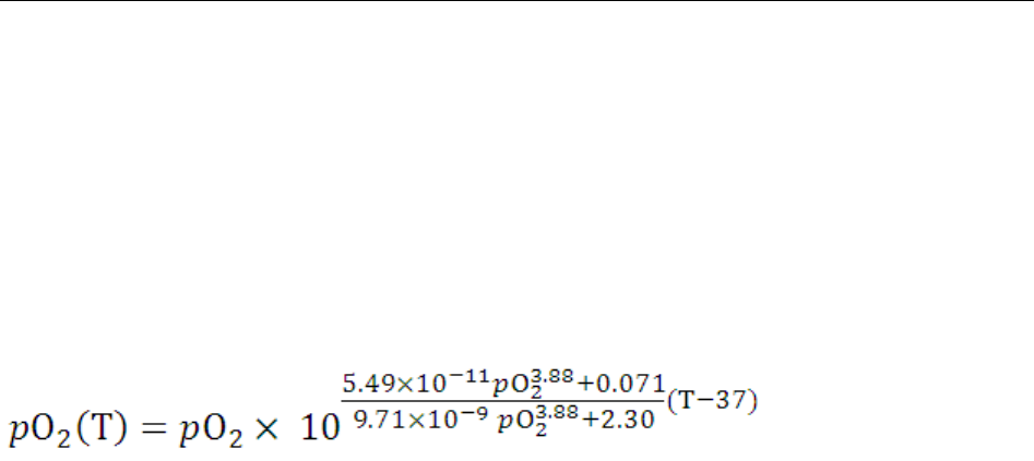
i15 Blood Gas and Chemistry Analysis System User Manual Theory
- 123 -
pCO2 (T)
pCO2 corrected for entered patient temperature
pCO2 (T) = pCO2 × 100.019(T - 37) [mmHg]
pO2 (T)
pO2 corrected for entered patient temperature
[mmHg]
pO2 (A-a) (T)
Alveolar-arterial oxygen tension difference corrected for entered patient temperature
pO2 (A-a) (T) = pO2 (A) (T) - pO2 (a) (T) [mmHg]
pO2 (a/A) (T)
Arterial-alveolar oxygen tension ratio corrected for entered patient temperature
pO2 (a/A) (T) = pO2 (a) (T) / pO2 (A) (T) [mmHg]
RI (T)
Respiratory index: the ratio of the alveolar-arterial blood oxygen-pressure difference to arterial
pO2 when both values are corrected for patient temperature
RI (T) = pO2 (A-a) (T) / pO2 (a) (T)
pO2 (T)/FIO2
The ratio of arterial pO2 to the fraction of inspired oxygen corrected for the entered patient
temperature
pO2 (T) / FIO2 = pO2 (T) / FIO2 [mmHg]

i15 Blood Gas and Chemistry Analysis System User Manual Parameters
- 124 -
Chapter 12 Parameters
12.1 pH
pH reflecting the acid-base status of a patient is the negative logarithm of the hydrogen ion
concentration.
pH is measured by potentiometry with a pH selective membrane electrode. The concentration of
hydrogen ions is determined by the measured potential through the Nernst equation.
If test results are inconsistent with the clinical assessment, the sample should be analyzed again
with a new test cartridge.
12.1.1 Intended Use
The pH test is intended for the quantification of pH in arterial, venous, or capillary whole blood
samples.
pH is an important clinical indicator to assess the acid-base imbalance caused by pathologic
conditions, such as ventilatory dysfunction and renal inadequency. The reasons for abnormal
blood pH values are:
primary bicarbonate deficit - metabolic acidosis
primary bicarbonate excess - metabolic alkalosis
primary hypoventilation - respiratory acidosis
primary hyperventilation - respiratory alkalosis
12.1.2 Traceability
pH values assigned to calibrant and controls are traceable to NIST standards.
12.1.3 Temperature Correction
pH is a temperature dependent quantity which is measured at 37°C on the system. The pH value
can be corrected to the patient’s temperature other than 37°C. Patient temperature can be entered
on the Enter Patient Information screen during each patient sample test.
The pH at the patient’s temperature is calculated as follows:
pH (T) = pH – [0.0147 + 0.0065(pH – 7.4)] (T – 37)

i15 Blood Gas and Chemistry Analysis System User Manual Parameters
- 125 -
12.1.4 Performance Characteristics
Experiments are designed according to the following CLSI guidelines: CLSI EP6-A for linearity
studies, CLSI EP9-A2 for method comparison studies, and CLSI EP7-A2 for interference studies.
Typical performance data presented below were obtained by technologists, nurses, physicians and
therapists trained in the use of the system and the comparative method.
Repeatability on RNA Medical® QC823 Blood Gas●Electrolyte●Metabolite●BUN controls was
estimated using one lot of test cartridges, and 20 replicates of each control level were successively
analyzed on one i15 Blood Gas and Chemistry Analysis System. RNA Medical® QC823 Blood
Gas●Electrolyte●Metabolite●BUN controls are traceable to NIST standards.
In the following repeatability data table below, SD refers to the standard deviation.
Controls Mean SD
Level 1 7.161 0.0061
Level 2 7.401 0.0104
Level 3 7.565 0.0074
Precision and recovery on whole blood samples was estimated using multiple whole blood
samples with pH values spanning the measurement range.
Parameter N Expected Observed Swr bias %Recovery
pH
9 7.085 7.110 0.021 0.025 100.4%
9 7.325 7.357 0.020 0.032 100.4%
9 7.581 7.559 0.011 -0.022 99.7%
9 7.656 7.673 0.010 0.017 100.2%
Linearity was estimated using reference materials and reference methods. Three replicates of
each level of materials were analyzed in parallel on the i15 Blood Gas and Chemistry Analysis
System and the Rapidpoint 400 system. Reference materials used were RNA Medical® CVC123
Calibration Verification Controls, and they were traceable to NIST standards. In the table below, Sy.x
refers to the standard error of estimate.

i15 Blood Gas and Chemistry Analysis System User Manual Parameters
- 126 -
Parameter N Slope Intercept Correlation
Coefficient Sy.x Range
pH 15 0.98 0.12 0.99996 0.00397 6.715 – 7.768
In the comparison study, samples were analyzed in parallel on the i15 Blood Gas and Chemistry
Analysis System and the Rapidpoint 400 system. Two replicates of each sample were analyzed
on each system.
Parameter N Slope Intercept Correlation
Coefficient Sy.x Range
pH 215 1.0259 -0.1934 0.9919 0.0126 7.137 – 7.720
12.1.5 Interfering Substances
Aqueous sample was spiked by addition of a potentially interfering substance to the following
test concentration to test for interferences. Twelve replicates of both the spiked sample and the
unspiked sample were tested on two i15 Blood Gas and Chemistry Analysis Systems with one lot
of test cartridges. The interference was computed using the difference between the mean of the
spiked sample and the unspiked sample.
The following substances were tested and found not to be clinically significant for the pH
measurement: 24mmol/L Hydroxyurea, 1.0mmol/L Magnesium, 20mmol/L Lactate, 4.00mmol/L
Salicyte, 37.5mmol/L Bromide, and 20mmol/L β-hydroxybutyrate.
NOTE:
It is possible that there are other substances interfering with the pH measurement.
12.2 pCO2
pCO2, the partial pressure of carbon dioxide, is measured by potentiometry. pCO2 is determined
by the measured potential through the Nernst equation.
If test results are inconsistent with the clinical assessment, the sample should be analyzed again
with a new test cartridge.
12.2.1 Intended Use
The pCO2 test is intended for the quantification of pCO2 in arterial, venous, or capillary whole
blood samples.

i15 Blood Gas and Chemistry Analysis System User Manual Parameters
- 127 -
pCO2 is an important indicator to reflect respiratory acid-base balance. If pCO2 is above the
normal range, it is termed respiratory acidosis. If pCO2 is below the normal range, it is termed
respiratory alkalosis. Metabolic factors can also cause pCO2 increase/decrease: metabolic
acidosis leads to decreased pCO2, and metabolic alkalosis leads to increased pCO2. pCO2 along
with pH is a more persuasive tool to assess acid-base balance.
12.2.2 Traceability
pCO2 values assigned to calibrant and controls are traceable to NIST standards.
12.2.3 Temperature Correction
pCO2 is a temperature dependent quantity which is measured at 37°C on the system. The pCO2
value can be corrected to the patient’s temperature other than 37°C. Patient temperature can be
entered on the Enter Patient Information screen during each patient sample test.
The pCO2 at the patient’s temperature is calculated as follows:
pCO2 (T) = pCO2 × 100.019(T - 37)
12.2.4 Performance Characteristics
Experiments are designed according to the following CLSI guidelines: CLSI EP6-A for linearity
studies, CLSI EP9-A2 for method comparison studies, and CLSI EP7-A2 for interference studies.
Typical performance data presented below were obtained by technologists, nurses, physicians and
therapists trained in the use of the system and the comparative method.
Repeatability on RNA Medical® QC823 Blood Gas●Electrolyte●Metabolite●BUN controls was
estimated using one lot of test cartridges, and 20 replicates of each level were successively analyzed
on one i15 Blood Gas and Chemistry Analysis System. RNA Medical® QC823 Blood
Gas●Electrolyte●Metabolite●BUN controls are traceable to NIST standards.
In the following repeatability data table below, SD refers to the standard deviation.
Controls Mean SD
Level 1 68.63 2.650
Level 2 43.97 1.368
Level 3 24.41 1.910
Precision and recovery on whole blood samples was estimated using multiple whole blood

i15 Blood Gas and Chemistry Analysis System User Manual Parameters
- 128 -
samples with pCO2 values spanning the measurement range.
Parameter N Expected Observed Swr bias %Recovery
pCO2
9 123.2 124.9 4.5 1.7 101.4%
9 42.8 42.5 1.2 -0.3 99.3%
9 21.3 20.1 1.5 -1.2 94.4%
9 10.6 10.0 1.1 -0.6 94.3%
Linearity was estimated using reference materials and reference methods. Three replicates of
each level of materials were analyzed in parallel on the i15 Blood Gas and Chemistry Analysis
System and the Rapidpoint 400 system. Reference materials used were RNA Medical® CVC123
Calibration Verification Controls, and they were traceable to NIST standards. In the table below, Sy.x
refers to the standard error of estimate.
Parameter N Slope Intercept Correlation
Coefficient Sy.x Range
pCO2 15 1.00 0.22 0.99998 0.215 17.8 – 84.0
In the comparison study, samples were analyzed in parallel on the i15 Blood Gas and Chemistry
Analysis System and the Rapidpoint 400 system. Two replicates of each sample were analyzed
on each system.
Parameter N Slope Intercept Correlation
Coefficient Sy.x Range
pCO2 215 0.9394 1.4498 0.9868 1.5950 11.5 – 73.8
12.2.5 Interfering Substances
Aqueous sample was spiked by addition of a potentially interfering substance to the following
test concentration to test for interferences. Twelve replicates of both the spiked sample and the
unspiked sample were tested on two i15 Blood Gas and Chemistry Analysis Systems with one lot
of test cartridges. The interference was computed using the difference between the mean of the
spiked sample and the unspiked sample.
The following substances were tested and found not to be clinically significant for the pCO2
measurement: 24mmol/L hydroxyurea, 1.0mmol/L magnesium, 20mmol/L lactate, 4.00mmol/L

i15 Blood Gas and Chemistry Analysis System User Manual Parameters
- 129 -
salicyte, 37.5mmol/L bromide, and 20mmol/L β-hydroxybutyrate.
NOTE:
It is possible that there are other substances interfering with the pCO2 measurement.
12.3 pO2
pO2, the partial pressure of oxygen, is measured by amperometry. The oxygen reduction current
is proportional to the dissolved oxygen concentration.
If test results are inconsistent with the clinical assessment, the sample should be analyzed again
with a new test cartridge.
12.3.1 Intended Use
The pO2 test is intended for the quantification of pO2 in arterial, venous, or capillary whole blood
samples.
The pO2 value of arterial blood is important in assesing the efficiency of pulmonary gas
exchange.
12.3.2 Traceability
pO2 values assigned to calibrant and controls are traceable to NIST standards.
12.3.3 Temperature Correction
pO2 is a temperature dependent quantity which is measured at 37°C on the system. The pO2 value
can be corrected to the patient’s temperature other than 37°C. Patient temperature can be entered
on the Enter Patient Information screen during each patient sample test.
The pO2 at the patient’s temperature is calculated as follows:
12.3.4 Performance Characteristics
Experiments are designed according to the following CLSI guidelines: CLSI EP6-A for linearity
studies, CLSI EP9-A2 for method comparison studies, and CLSI EP7-A2 for interference studies.
Typical performance data presented below were obtained by technologists, nurses, physicians and

i15 Blood Gas and Chemistry Analysis System User Manual Parameters
- 130 -
therapists trained in the use of the system and the comparative method.
Repeatability on RNA Medical® QC823 Blood Gas●Electrolyte●Metabolite●BUN controls was
estimated using one lot of test cartridges, and 20 replicates of each level were successively analyzed
on one i15 Blood Gas and Chemistry Analysis System. RNA Medical® QC823 Blood
Gas●Electrolyte●Metabolite●BUN controls are traceable to NIST standards.
In the following repeatability data table below, SD refers to the standard deviation.
Controls Mean SD
Level 1 65.3 2.95
Level 2 103.0 3.02
Level 3 150.8 4.65
Precision and recovery on whole blood samples was estimated using multiple whole blood
samples with pO2 values spanning the measurement range.
Parameter N Expected Observed Swr bias %Recovery
pO2
9 21.4 21.7 1.3 0.3 101.4%
9 149.7 151.6 3.7 1.9 101.3%
9 271.8 270.8 8.0 -1.0 99.6%
9 422.2 421.7 18.7 -0.5 99.9%
Linearity was estimated using reference materials and reference methods. Three replicates of
each level of materials were analyzed in parallel on the i15 Blood Gas and Chemistry Analysis
System and the Rapidpoint 400 system. Reference materials used were RNA Medical® CVC123
Calibration Verification Controls, and they were traceable to NIST standards. In the table below, Sy.x
refers to the standard error of estimate.
Parameter N Slope Intercept Correlation
Coefficient Sy.x Range
pO2 15 0.92 4.51 0.99989 2.58604 39.6 – 448.2
In the comparison study, samples were analyzed in parallel on the i15 Blood Gas and Chemistry
Analysis System and the Rapidpoint 400 system. Two replicates of each sample were analyzed
on each system.

i15 Blood Gas and Chemistry Analysis System User Manual Parameters
- 131 -
Parameter N Slope Intercept Correlation
Coefficient Sy.x Range
pO2 215 0.9811 1.3173 0.9986 2.0303 20.4 – 191.0
12.3.5 Interfering Substances
Aqueous sample was spiked by addition of a potentially interfering substance to the following
test concentration to test for interferences. Twelve replicates of both the spiked sample and the
unspiked sample were tested on two i15 Blood Gas and Chemistry Analysis Systems with one lot
of test cartridges. The interference was computed using the difference between the mean of the
spiked sample and the unspiked sample.
The following substances were tested and found not to be clinically significant for the pO2
measurement: 24mmol/L hydroxyurea, 1.0mmol/L magnesium, 20mmol/L lactate, 4.00mmol/L
salicyte, 37.5mmol/L bromide, and 20mmol/L β-hydroxybutyrate.
NOTE:
It is possible that there are other substances interfering with the pO2 measurement.
12.4 Sodium (Na+)
Sodium is measured by potentiometry with an ion-selective electrode. The concentration of
sodium ions is determined by the measured potential through the Nernst equation. The system
uses a direct (undiluted) method to measure sodium and the obtained values may differ from
those obtained by an indirect (diluted) method.
If test results are inconsistent with the clinical assessment, the sample should be analyzed again
with a new test cartridge.
12.4.1 Intended Use
The sodium test is intended for the quantification of sodium in arterial, venous, or capillary whole
blood samples.
Sodium is the major cation in the extracellular space in the body. It plays an important part in
maintaining osmotic pressure and acid-base balance.
Monitoring blood sodium level is important in the diagnosis or monitoring of diseases involving
electrolyte imbalance and all disturbances of the water balance, heart and kidney insufficiencies,

i15 Blood Gas and Chemistry Analysis System User Manual Parameters
- 132 -
and so on.
12.4.2 Traceability
Sodium ion concentration values assigned to calibrant and controls are traceable to NIST
standards.
12.4.3 Performance Characteristics
Experiments are designed according to the following CLSI guidelines: CLSI EP6-A for linearity
studies, CLSI EP9-A2 for method comparison studies, and CLSI EP7-A2 for interference studies.
Typical performance data presented below were obtained by technologists, nurses, physicians and
therapists trained in the use of the system and the comparative method.
Repeatability on RNA Medical® QC823 Blood Gas●Electrolyte●Metabolite●BUN controls was
estimated using one lot of test cartridges, and 20 replicates of each level were successively analyzed
on one i15 Blood Gas and Chemistry Analysis System. RNA Medical® QC823 Blood
Gas●Electrolyte●Metabolite●BUN controls are traceable to NIST standards.
In the following repeatability data table below, SD refers to the standard deviation.
Controls Mean SD
Level 1 114.6 0.83
Level 2 140.1 0.83
Level 3 168.7 0.92
Precision and recovery on whole blood samples was estimated using multiple whole blood
samples with Na+ values spanning the measurement range.
Parameter N Expected Observed Swr bias %Recovery
Na+
9 111.2 111.7 0.7 0.5 100.4%
9 140.5 140.8 1.6 0.3 100.2%
9 166.0 167.3 3.1 1.3 100.8%
Linearity was estimated using reference materials and reference methods. Three replicates of
each level of materials were analyzed in parallel on the i15 Blood Gas and Chemistry Analysis
System and the Rapidpoint 400 system. Reference materials used were RNA Medical® CVC123
Calibration Verification Controls, and they were traceable to NIST standards. In the table below, Sy.x

i15 Blood Gas and Chemistry Analysis System User Manual Parameters
- 133 -
refers to the standard error of estimate.
Parameter N Slope Intercept Correlation
Coefficient Sy.x Range
Na+ 15 0.98 1.30 0.99999 0.1924 102.6 – 180.3
In the comparison study, samples were analyzed in parallel on the i15 Blood Gas and Chemistry
Analysis System and the Rapidpoint 400 system. Two replicates of each sample were analyzed
on each system.
Parameter N Slope Intercept Correlation
Coefficient Sy.x Range
Na+ 215 0.9813 2.3952 0.9961 1.1661 102.3 – 164.9
12.4.4 Interfering Substances
Aqueous sample was spiked by addition of a potentially interfering substance to the following
test concentration to test for interferences. Twelve replicates of both the spiked sample and the
unspiked sample were tested on two i15 Blood Gas and Chemistry Analysis Systems with one lot
of test cartridges. The interference was computed using the difference between the mean of the
spiked sample and the unspiked sample.
The substances that interfere with the Na+ measurement are listed below:
37.5mmol/L bromide will increase Na+ results by 5.5mmol/L.
The following substances were tested and found not to be clinically significant for the Na+
measurement: 24mmol/L hydroxyurea, 1.0mmol/L magnesium, 20mmol/L lactate, 4.00mmol/L
salicyte, 12.5mmol/L bromide, and 20mmol/L β-hydroxybutyrate.
NOTE:
It is possible that there are other substances interfering with the Na+ measurement.
12.5 Potassium (K+)
Potassium is measured by potentiometry with an ion-selective electrode. The concentration of
potassium ions is determined by the measured potential through the Nernst equation. The system
uses a direct (undiluted) method to measure potassium and the obtained values may differ from
those obtained by an indirect (diluted) method.

i15 Blood Gas and Chemistry Analysis System User Manual Parameters
- 134 -
If test results are inconsistent with the clinical assessment, the sample should be analyzed again
with a new test cartridge.
12.5.1 Intended Use
The Potassium test is intended for the quantification of potassium in arterial, venous, or capillary
whole blood samples.
Potassium is the most abundant cation in the intracellular fluid, and plays an important role in
nerve conduction and muscle function. It also helps maintain acid-base balance and osmotic
pressure.
Potassium value is important for patients who are undergoing infusion therapies, who are
experiencing heart insufficiency, and so on.
12.5.2 Traceability
Potassium ion concentration values assigned to calibrant and controls are traceable to NIST
standards.
12.5.3 Performance Characteristics
Experiments are designed according to the following CLSI guidelines: CLSI EP6-A for linearity
studies, CLSI EP9-A2 for method comparison studies, and CLSI EP7-A2 for interference studies.
Typical performance data presented below were obtained by technologists, nurses, physicians and
therapists trained in the use of the system and the comparative method.
Repeatability on RNA Medical® QC823 Blood Gas●Electrolyte●Metabolite●BUN controls was
estimated using one lot of test cartridges, and 20 replicates of each level were successively analyzed
on one i15 Blood Gas and Chemistry Analysis System. RNA Medical® QC823 Blood
Gas●Electrolyte●Metabolite●BUN controls are traceable to NIST standards.
In the following repeatability data table below, SD refers to the standard deviation.
Controls Mean SD
Level 1 1.92 0.014
Level 2 4.51 0.041
Level 3 6.70 0.047
Precision and recovery on whole blood samples was estimated using multiple whole blood

i15 Blood Gas and Chemistry Analysis System User Manual Parameters
- 135 -
samples with K+ values spanning the measurement range.
Parameter N Expected Observed Swr bias %Recovery
K+
9 3.40 3.35 0.04 -0.05 98.5%
9 4.00 4.01 0.03 0.01 100.3%
9 9.37 9.36 0.20 -0.01 99.9%
Linearity was estimated using reference materials and reference methods. Three replicates of
each level of materials were analyzed in parallel on the i15 Blood Gas and Chemistry Analysis
System and the Rapidpoint 400 system. Reference materials used were RNA Medical® CVC123
Calibration Verification Controls, and they were traceable to NIST standards. In the table below, Sy.x
refers to the standard error of estimate.
Parameter N Slope Intercept Correlation
Coefficient Sy.x Range
K+ 15 1.0 -0.04 0.99997 0.03787 1.82 – 12.09
In the comparison study, samples were analyzed in parallel on the i15 Blood Gas and Chemistry
Analysis System and the Rapidpoint 400 system. Two replicates of each sample were analyzed
on each system.
Parameter N Slope Intercept Correlation
Coefficient Sy.x Range
K+ 215 1.0068 -0.0409 0.9983 0.0594 2.55 – 6.70
12.5.4 Interfering Substances
Aqueous sample was spiked by addition of a potentially interfering substance to the following
test concentration to test for interferences. Twelve replicates of both the spiked sample and the
unspiked sample were tested on two i15 Blood Gas and Chemistry Analysis Systems with one lot
of test cartridges. The interference was computed using the difference between the mean of the
spiked sample and the unspiked sample.
The following substances were tested and found not to be clinically significant for the K+
measurement: 24mmol/L hydroxyurea, 1.0mmol/L magnesium, 20mmol/L lactate, 4.00mmol/L
salicyte, 37.5mmol/L bromide, and 20mmol/L β-hydroxybutyrate.

i15 Blood Gas and Chemistry Analysis System User Manual Parameters
- 136 -
NOTE:
It is possible that there are other substances interfering with the K+ measurement.
12.6 Ionized Calcium (Ca++)
Ionized calcium (Ca++) is measured by potentiometry with an ion-selective electrode. The
concentration of ionized calcium is determined by the measured potential through the Nernst
equation.
If test results are inconsistent with the clinical assessment, the sample should be analyzed again
with a new test cartridge.
12.6.1 Intended Use
The ionized calcium test is intended for the quantification of ionized calcium in arterial, venous,
or capillary whole blood samples.
Ca++, the physiologically active form of calcium, plays an important role in muscle contraction,
transmission of nerve impulses, and cardiac functions.
For patients who are in critical care situations, especially those who need to receive large
amounts of blood, the Ca++ level should be monitored closely.
12.6.2 Traceability
Ionized calcium concentration values assigned to calibrant and controls are traceable to NIST
standards.
12.6.3 Performance Characteristics
Experiments are designed according to the following CLSI guidelines: CLSI EP6-A for linearity
studies, CLSI EP9-A2 for method comparison studies, and CLSI EP7-A2 for interference studies.
Typical performance data presented below were obtained by technologists, nurses, physicians and
therapists trained in the use of the system and the comparative method.
Repeatability on RNA Medical® QC823 Blood Gas●Electrolyte●Metabolite●BUN controls was
estimated using one lot of test cartridges, and 20 replicates of each level were successively analyzed
on one i15 Blood Gas and Chemistry Analysis System. RNA Medical® QC823 Blood
Gas●Electrolyte●Metabolite●BUN controls are traceable to NIST standards.
In the following repeatability data table below, SD refers to the standard deviation.

i15 Blood Gas and Chemistry Analysis System User Manual Parameters
- 137 -
Controls Mean SD
Level 1 1.47 0.029
Level 2 1.16 0.026
Level 3 0.46 0.019
Precision and recovery on whole blood samples was estimated using multiple whole blood
samples with Ca++ values spanning the measurement range.
Parameter N Expected Observed Swr bias %Recovery
Ca++
9 1.05 1.05 0.03 0.00 100.0%
9 1.21 1.20 0.01 -0.01 99.2%
9 2.68 2.68 0.07 0.00 100.0%
Linearity was estimated using reference materials and reference methods. Three replicates of
each level of materials were analyzed in parallel on the i15 Blood Gas and Chemistry Analysis
System and the Rapidpoint 400 system. Reference materials used were RNA Medical® CVC123
Calibration Verification Controls, and they were traceable to NIST standards. In the table below, Sy.x
refers to the standard error of estimate.
Parameter N Slope Intercept Correlation
Coefficient Sy.x Range
Ca++ 15 0.98 0.37 0.99998 0.00972 0.15 – 3.74
In the comparison study, samples were analyzed in parallel on the i15 Blood Gas and Chemistry
Analysis System and the Rapidpoint 400 system. Two replicates of each sample were analyzed
on each system.
Parameter N Slope Intercept Correlation
Coefficient Sy.x Range
Ca++ 215 0.9987 0.0019 0.9910 0.0265 0.61 – 1.73
12.6.4 Interfering Substances
Aqueous sample was spiked by addition of a potentially interfering substance to the following
test concentration to test for interferences. Twelve replicates of both the spiked sample and the

i15 Blood Gas and Chemistry Analysis System User Manual Parameters
- 138 -
unspiked sample were tested on two i15 Blood Gas and Chemistry Analysis Systems with one lot
of test cartridges. The interference was computed using the difference between the mean of the
spiked sample and the unspiked sample.
The substances that interfere with the Ca++ measurement are listed below:
12.5mmol/L bromide will increase Ca++ results by 0.07mmol/L.
37.5mmol/L bromide will increase Ca++ results by 0.17mmol/L.
The following substances were tested and found not to be clinically significant for the Ca++
measurement: 24mmol/L hydroxyurea, 1.0mmol/L magnesium, 20mmol/L lactate, 4.00mmol/L
salicyte, and 20mmol/L β-hydroxybutyrate.
NOTE:
It is possible that there are other substances interfering with the Ca++ measurement.
12.7 Chloride (Cl-)
Chloride is measured by potentiometry with an ion-selective electrode. The concentration of
chloride ions is determined by the measured potential through the Nernst equation. The system
uses a direct (undiluted) method to measure chloride, and the obtained values may differ from
those obtained by an indirect (diluted) method.
If test results are inconsistent with the clinical assessment, the sample should be analyzed again
with a new test cartridge.
12.7.1 Intended Use
The chloride test is intended for the quantification of chloride in arterial, venous, or capillary
whole blood samples.
Cl-, the major anion in the extracellular space in the body, plays a role in the regulation of the
acid-base balance, and regulates osmotic pressure together with Na+.
Monitoring Cl- value is vital for patients who suffer from hypertension, cardiac distress, etc.
12.7.2 Traceability
Chloride ion concentration values assigned to calibrant and controls are traceable to NIST
standards.

i15 Blood Gas and Chemistry Analysis System User Manual Parameters
- 139 -
12.7.3 Performance Characteristics
Experiments are designed according to the following CLSI guidelines: CLSI EP6-A for linearity
studies, CLSI EP9-A2 for method comparison studies, and CLSI EP7-A2 for interference studies.
Typical performance data presented below were obtained by technologists, nurses, physicians and
therapists trained in the use of the system and the comparative method.
Repeatability on RNA Medical® QC823 Blood Gas●Electrolyte●Metabolite●BUN controls was
estimated using one lot of test cartridges, and 20 replicates of each level were successively analyzed
on one i15 Blood Gas and Chemistry Analysis System. RNA Medical® QC823 Blood
Gas●Electrolyte●Metabolite●BUN controls are traceable to NIST standards.
In the following repeatability data table below, SD refers to the standard deviation.
Controls Mean SD
Level 1 78.8 0.62
Level 2 96.7 0.84
Level 3 127.1 0.76
Precision and recovery on whole blood samples was estimated using multiple whole blood
samples with Cl- values spanning the measurement range.
Parameter N Expected Observed Swr bias %Recovery
Cl-
9 80.0 80.0 0.3 0.0 100.0%
9 106.5 106.6 1.3 0.1 100.1%
9 133.0 133.0 1.8 0.0 100.0%
Linearity was estimated using reference materials and reference methods. Three replicates of
each level of materials were analyzed in parallel on the i15 Blood Gas and Chemistry Analysis
System and the Rapidpoint 400 system. Reference materials used were RNA Medical® CVC123
Calibration Verification Controls, and they were traceable to NIST standards. In the table below, Sy.x
refers to the standard error of estimate.
Parameter N Slope Intercept Correlation
Coefficient Sy.x Range
Cl- 15 0.98 0.37 0.99998 0.2404 72 - 146

i15 Blood Gas and Chemistry Analysis System User Manual Parameters
- 140 -
In the comparison study, samples were analyzed in parallel on the i15 Blood Gas and Chemistry
Analysis System and the Rapidpoint 400 system. Two replicates of each sample were analyzed
on each system.
Parameter N Slope Intercept Correlation
Coefficient Sy.x Range
Cl- 215 0.9955 0.2967 0.9961 0.9802 77 - 132
12.7.4 Interfering Substances
Aqueous sample was spiked by addition of a potentially interfering substance to the following
test concentration to test for interferences. Twelve replicates of both the spiked sample and the
unspiked sample were tested on two i15 Blood Gas and Chemistry Analysis Systems with one lot
of test cartridges. The interference was computed using the difference between the mean of the
spiked sample and the unspiked sample.
The substances interfering with the Cl- measurement are listed below:
12.5mmol/L bromide will increase Cl- results by 15.5mmol/L.
4.00mmol/L salicyte will increase Cl- results by 15.0mmol/L.
The following substances were tested and found not to be clinically significant for the Cl-
measurement: 24mmol/L hydroxyurea, 1.0mmol/L magnesium, 20mmol/L lactate, and 20mmol/L
β-hydroxybutyrate.
NOTE:
It is possible that there are other substances interfering with the Cl- measurement.
12.8 Hematocrit (Hct)
Hematocrit is a measurement of the volume occupied by red blood cells in whole blood samples.
Hematocrit is determined by conductometry with two gold electrodes. The conductance of the
blood sample is inversely related to the hematocrit value.
If test results are inconsistent with the clinical assessment, the sample should be analyzed again
with a new test cartridge.

i15 Blood Gas and Chemistry Analysis System User Manual Parameters
- 141 -
12.8.1 Intended Use
The hematocrit test is intended for the quantification of hematocrit in arterial, venous, or capillary
whole blood samples.
Hematocrit is a useful indicator for assessing states of blood volume, such as anemia and
erythrocytosis.
12.8.2 Traceability
Hematocrit values assigned to calibrant and controls are traceable to NIST standards.
12.8.3 Performance Characteristics
Experiments are designed according to the following CLSI guidelines: CLSI EP6-A for linearity
studies, CLSI EP9-A2 for method comparison studies, and CLSI EP7-A2 for interference studies.
Typical performance data presented below were obtained by technologists, nurses, physicians and
therapists trained in the use of the system and the comparative method.
Repeatability on RNA Medical® QC900 Hematocrit controls was estimated using one lot of test
cartridges, and 20 replicates of each level were successively analyzed on one i15 Blood Gas and
Chemistry Analysis System. RNA Medical® QC900 Hematocrit controls are traceable to NIST
standards.
In the following repeatability data table below, SD refers to the standard deviation.
Controls Mean SD
Low 20.3 0.93
High 49.7 0.47
Precision and recovery on whole blood samples was estimated using multiple whole blood
samples with Hct values spanning the measurement range.
Parameter N Expected Observed Swr bias %Recovery
Hct
9 25.5 26.2 0.5 0.7 102.7%
9 44.0 44.6 0.9 0.6 101.4%
9 64.0 62.5 1.5 -1.5 97.7%
Linearity was estimated using reference materials and reference methods. Three replicates of

i15 Blood Gas and Chemistry Analysis System User Manual Parameters
- 142 -
each level of materials were analyzed in parallel on the i15 Blood Gas and Chemistry Analysis
System and the Rapidpoint 400 system. Reference materials used were RNA Medical® CVC 9005
Hematocrit Calibration Verification Controls, and they were traceable to NIST standards. In the table
below, Sy.x refers to the standard error of estimate.
Parameter N Slope Intercept Correlation
Coefficient Sy.x Range
Hct 15 0.99 0.56 0.99988 0.34811 15.0 – 62.0
In the comparison study, samples were analyzed in parallel on the i15 Blood Gas and Chemistry
Analysis System and the Rapidpoint 400 system. Two replicates of each sample were analyzed
on each system.
Parameter N Slope Intercept Correlation
Coefficient Sy.x Range
Hct 215 0.9729 1.0199 0.9932 0.7518 23 - 53
12.8.4 Interfering Substances
The substances interfering with the hematocrit measurement are listed below:
A significant increase in white blood cell count may increase the hematocrit results.
Total protein level will increase the hematocrit results.
Abnormally high lipids may increase the hematocrit results.
Factors interfering with sodium results will also interfering with hematocrit results.
NOTE:
It is possible that there are other substances interfering with the hematocrit
measurement.

i15 Blood Gas and Chemistry Analysis System User Manual Warranty and Service
- 143 -
Chapter 13 Warranty and Service
13.1 Warranty
EDAN warrants that EDAN’s products meet the labeled specifications of the products and
will be free from defects in materials and workmanship that occur within the warranty
period.
The warranty is void in cases of:
a) Damage caused by mishandling during shipping.
b) Subsequent damage caused by improper use or maintenance.
c) Damage caused by alteration or repair by anyone not authorized by EDAN.
d) Damage caused by accidents.
e) Replacement or removal of serial number label and manufacture label.
If a product covered by this warranty is determined to be defective because of defective
materials, components, or workmanship, and the warranty claim is made within the warranty
period, EDAN will, at its discretion, repair or replace the defective part(s) free of charge.
EDAN will not provide a substitute product for use when the defective product is being
repaired.
13.2 Contact Information
If you have any question about maintenance, technical specifications or malfunctions of
devices, contact your local distributor.
Alternatively, you can send an email to EDAN service department at: support@edan.com.cn.

i15 Blood Gas and Chemistry Analysis System User Manual Specifications
- 144 -
Appendix 1 Specifications
A1.1 Environment Requirements
Analyzer
Usage
Temperature 10 - 31°C
Humidity 25% - 80% (non-condensing)
Ambient
Pressure
70 - 106.6kPa
(525 - 800mmHg)
Transport and
Storage
Temperature -20 - 60°C
Humidity 25% - 93% (non-condensing)
Ambient
Pressure
40 - 106.6kPa
(300 - 800mmHg)
Test
Cartridge
Usage
Temperature 10 - 31°C
Humidity 25% - 80% (non-condensing)
Ambient
Pressure
70 - 106.6kPa
(525 - 800mmHg)
Transport
Temperature 4 - 37°C
Humidity ≤ 93% (non-condensing)
Ambient
Pressure
40 - 106.6kPa
(300 - 800mmHg)
Storage
Temperature 4 - 30°C
Humidity ≤ 93% (non-condensing)
Ambient
Pressure
40 - 106.6kPa
(300 - 800mmHg)
Calibrant
Fluid Pack
Usage
Temperature 10 - 31°C
Humidity 25% - 80% (non-condensing)
Ambient
Pressure
70 - 106.6kPa
(525 - 800mmHg)
Transport and
Storage
Temperature 2 - 8°C (avoid freezing)
Humidity ≤ 93% (non-condensing)
Ambient
Pressure
65 - 106.6kPa
(489 - 800mmHg)
Controls Usage Temperature 10 - 31°C
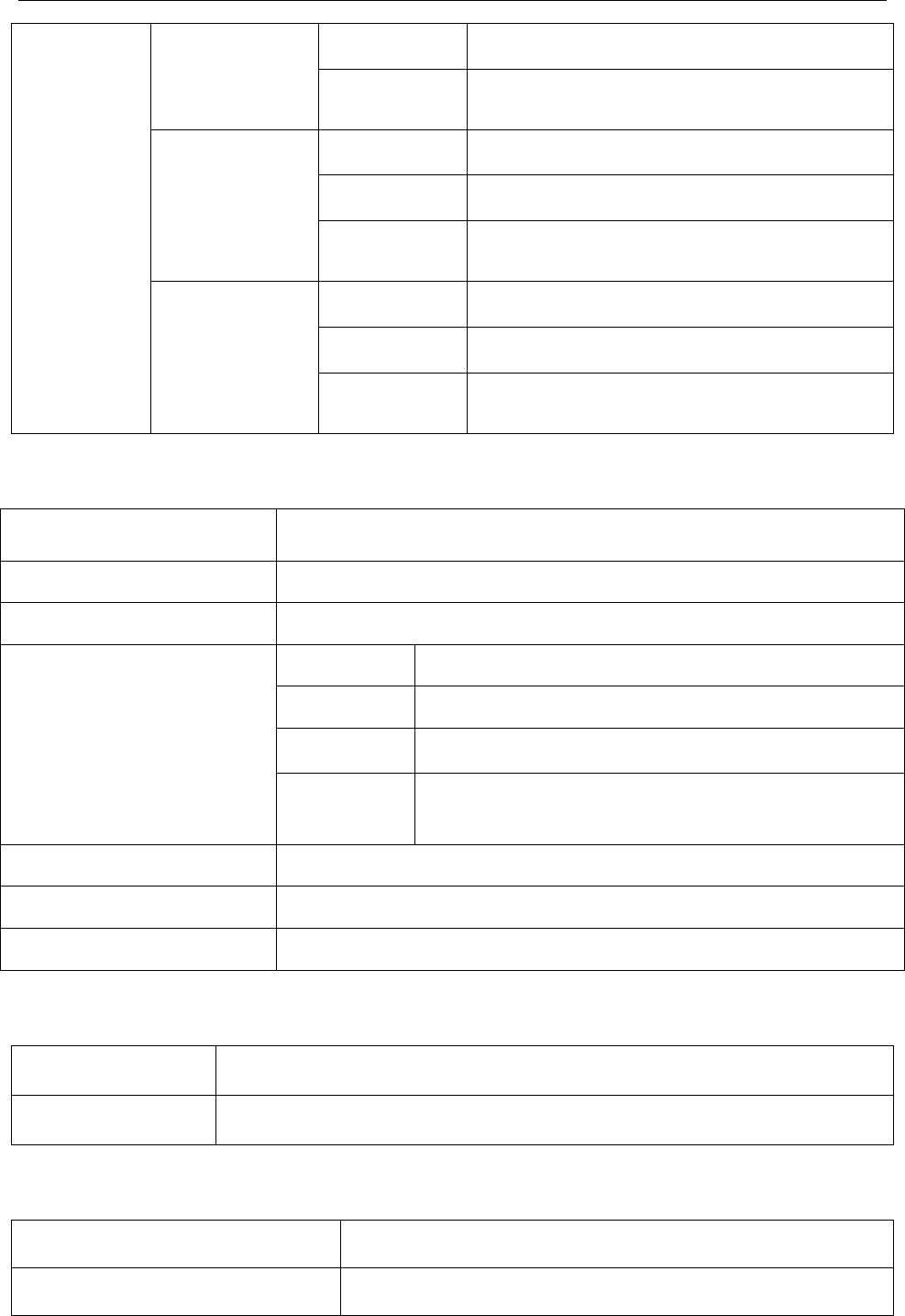
i15 Blood Gas and Chemistry Analysis System User Manual Specifications
- 145 -
Humidity 25% - 80% (non-condensing)
Ambient
Pressure
70 - 106.6kPa
(525 - 800mmHg)
Transport
Temperature 2 - 30°C
Humidity 25% - 93% (non-condensing)
Ambient
Pressure
40 - 106.6kPa
(300 - 800mmHg)
Storage
Temperature 2 - 8°C (avoid freezing)
Humidity 25% - 93% (non-condensing)
Ambient
Pressure
40 - 106.6kPa
(300 - 800mmHg)
A1.2 Analyzer Specifications
Size 315*238*153mm (length ×width ×height)
Weight 3.8Kg (rechargeable battery included, adaptor not included)
LCD Screen 7 inch, 800*480, Color TFT
Power
Voltage 100V - 240V~
Input Current 1.2A - 0.5A
Frequency 50Hz/60Hz
Rechargeable
Battery 14.8VDC/4200mAh
USB Interface 4 USB Interfaces
Serial Port DB9
Bar Code Scanner embedded
A1.3 Performance Specifications
Sample Volume 110uL
Test Time It takes no more than 70s from sampling to display of test results.
A1.4 Printer
Printer Built-in thermal printer, thermal printer paper
Paper Width 48mm

i15 Blood Gas and Chemistry Analysis System User Manual Specifications
- 146 -
A1.5 Rechargeable Battery
Type Rechargeable lithium battery
Working Time When the battery is fully charged, the system can analyze and print
50 samples.
Necessary Charge time No more than 8 hours
Rated Capacity 4200mAh
Rated voltage 14.8V
Charge Mode Constant voltage/current
Charge Current (standard) 0.2C5A
Charge Temperature 0°C - +50°C (+32°F - +122°F)
Operating Temperature -20°C - +60°C (-4°F - +140°F)
Storage
Short Term (within 1 month): -20°C - +60°C (-4ºF - +140ºF)
Middle Term (within 3 months): -20°C - +45°C (-4ºF - +113ºF)
Long Term (within 1 year): -20°C - +20°C (-4ºF - +68ºF)
During storage, recharge the battery at least every six months.
Cycle Life ≥300 times
A1.6 Safety Specifications
Comply with EN 61010-1: 2001, EN 61010-2-101: 2002,
EN 61326-1: 2006, EN 61326-2-6: 2006
Degree of protection against
harmful ingress of water Ordinary equipment (Sealed equipment without water proof)
Degree of safety in presence
of flammable gases Equipment not suitable for use in presence of flammable gases
EMC CISPR 11 Group 1, Class A
Electric shock Class I
Mode of operation Continuous

i15 Blood Gas and Chemistry Analysis System User Manual Measurement Ranges
- 147 -
Appendix 2 Measurement Ranges
A2.1 Measurement Ranges for Measured Parameters
Parameter Measurement Range
pH 6.500 - 8.000
pO2 10 - 700mmHg
pCO2 10 - 150mmHg
K
+
2.0 - 9.0mmol/L
Na
+
100 - 180mmol/L
Cl
-
65 - 140mmol/L
Ca
++
0.25 - 2.50mmol/L
Hct 10 - 75 %PCV
A2.2 Measurement Ranges for Calculated Parameters
Parameter Measurement Range
cH
+
10.0 - 316.2nmol/L
cH
+
(T) 10.0 - 316.2nmol/L
pH(T) 6.500 - 8.000
pCO
2
(T) 10.0 - 150.0mmHg
pO2(T) 10 - 700mmHg
HCO3
-
act 1.0 - 99.9mmol/L
HCO3
-
std 1.0 - 99.9mmol/L
BB(B) 13.1 - 82.4mmol/L
BE(B) (-30.0) - (+30.0)mmol/L
BE(ecf) (-30.0) - (+30.0)mmol/L
ctCO2 1 - 100mmol/L
Ca
++
(7.4) 0.23 - 2.70mmol/L
sO2(est) 1% – 100%
AnGap (-10) - (+99)mmol/L
tHb(est) 3.4 - 25.5g/dL
pO2(A-a) 0 - 733mmHg
pO2(A-a)(T) 0 - 733mmHg
pO2(a/A) 0.00 - 1.00
pO
2
(a/A)(T) 0.00 - 1.00
RI 0.00 - 20.00
RI(T) 0.00 - 20.00
pO2/FIO2 250 - 700mmHg
pO2(T)/FIO2 250 - 700mmHg

i15 Blood Gas and Chemistry Analysis System User Manual Reference Ranges
- 148 -
Appendix 3 Reference Ranges
NOTE:
Because reference ranges may vary with demographic factors such as age, gender and
heritage, it is recommended that the individual institutions should establish their own
reference ranges according to the population being tested. The following reference
ranges are for reference only.
Parameter Reference Range
Arterial Venous
pH 7.35 - 7.45 7.31 - 7.41
pO2(mmHg) 80 - 105 35 - 40
pCO2(mmHg) 35 - 45 41 - 51
Na
+
(mmol/L) 138 - 146 138 - 146
K
+
(mmol/L) 3.5 - 4.9 3.5 - 4.9
Cl
-
(mmol/L) 98 - 109 98 - 109
Ca
++
(mmol/L) 1.12 - 1.32 1.12 - 1.32
Hct (%) 38 - 51 38 - 51

i15 Blood Gas and Chemistry Analysis System User Manual EMC Information
- 149 -
Appendix 4 EMC Information
Guidance and manufacture’s declaration - electromagnetic emissions-
for all EQUIPMENT and SYSTEMS
Guidance and manufacture’s declaration – electromagnetic emission
The system is intended for use in the electromagnetic environment specified below. The user of
the system should ensure that it is used in such an environment.
Emission test Compliance Electromagnetic environment – guidance
RF emissions
CISPR 11 Group 1
The system
uses RF energy only for its internal
function. Therefore, its RF emissions are very low and
are not likely to cause any interference to nearby
electronic equipment.
RF emissions
CISPR 11 Class A
The system
is suitable for use in all establishments
other than domestic and those directly connected to the
public low-voltage power supply network that supplies
buildings used for domestic purposes.
Harmonic
emissions
IEC 61000-3-2
Class A
Voltage
fluctuations/ flicker
emissions
IEC 61000-3-3
Complies
Guidance and manufacture’s declaration - electromagnetic immunity -
for all EQUIPMENT and SYSTEMS
Guidance and manufacture’s declaration – electromagnetic immunity
The system is intended for use in the electromagnetic environment specified below. The customer
or the user of the system should ensure that it is used in such an environment.
Immunity test IEC
61326-1&61326-2-6
test level
Compliance level Electromagnetic
environment -guidance
Electrostatic
discharge (ESD)
IEC 61000-4-2
±4kV contact
±8kV air
±4kV contact
±8kV air
Floors should be wood,
concrete or ceramic tile.
If floor is covered with
synthetic material, the
relative h
umidity should
be at least 30%.

i15 Blood Gas and Chemistry Analysis System User Manual EMC Information
- 150 -
Electrical fast
transient/burst IEC
61000-4-4
±1kV for power supply
lines
±1kV for power supply
lines
Mains power quality
should be that of a typical
comm
ercial or hospital
environment.
Surge
IEC 61000-4-5
±1kV line to line
±2kV line to ground
±1kV line to line
±2kV line to ground
Mains power quality
should be that of a typical
comm
ercial or hospital
environment.
Power frequency
(50Hz/60Hz)
magnetic field
IEC 61000-4-8
3A/m 3A/m Power frequency
magnetic fields should be
at levels characteristic of
a typical location in a
typical commercial or
hospital environment.
Voltage dips, short
interruptions and
voltage variations
on power supply
input lines
IEC 61000-4-11
<5% UT (>95% dip in
UT) for 1 cycle
40%
UT (60% dip in
UT) for 5/6 cycles
70% UT
(30% dip in
UT) for 25/30 cycles
<5% UT (>95% dip in
UT) for 250/300 cycles
<5% UT (>95% dip in
UT) for 1 cycle
40%
UT (60% dip in
UT) for 5/6 cycles
70% U
T (30% dip in
UT) for 25/30 cycles
<5% UT (>95% dip in
UT) for 250/300 cycles
Mains power quality
should be that of a typical
commercial or hospital
environment. If the user
of the system requires
continuous operation
during power mains
interruptions, it is
recommended that the
system be powered from
an uninterruptible power
supply or a battery.
NOTE UT is the a.c. mains voltage prior to application of the test level.
Guidance and manufacturer’s declaration – electromagnetic immunity –
for EQUIPMENT and SYSTEMS that are not LIFE-SUPPORTING
Guidance and manufacture’s declaration – electromagnetic immunity
The system is intended for use in the electromagnetic environment specified below. The customer
or the user of the system should ensure that it is used in such an environment.
Immunity
test
IEC
60601
&61326
test
level
Compliance
level Electromagnetic environment -guidance
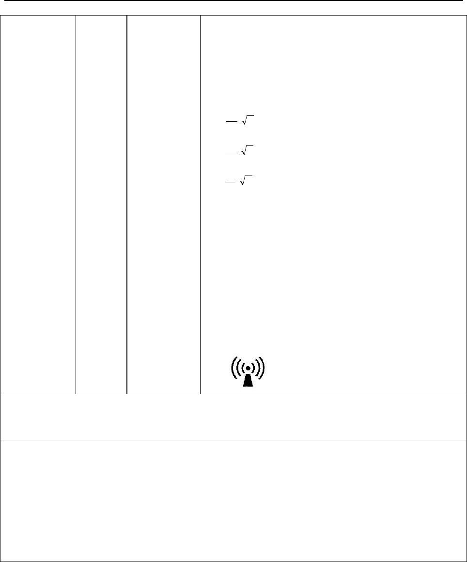
i15 Blood Gas and Chemistry Analysis System User Manual EMC Information
- 151 -
Conducted
RF IEC
61000-4-6
Radiated RF
IEC
61000-4-3
3Vrms
150kHz
to
80MHz
3V/m
80MHz
to
2.7GHz
3Vrms
3V/m
Portable and mobile RF communications equipment
should be used no closer to any part of the system,
including cables, than the recommended separation
distance calculated from the equation applicable to the
frequency of the transmitter.
Recommended separation distance
P
V
d
=
1
5.3
P
E
d
=
1
5.3
80MHz to 800MHz
P
E
d
=
1
7
800MHz to 2.7GHz
Where P is the maximum output power rating of the
transmitter in watts (W) according to the transmitter
manufacturer and d is the recommended separation
distance in metres (m).
Field strengths from fixed RF transmitters, as
determined by an electromagnetic site survey,a should
be less than the compliance level in each frequency
range.b
Interference may occur in the vicinity of equipment
marked with the following symbol:
NOTE 1: At 80MHz and 800MHz, the higher frequency range applies.
NOTE 2:
These guidelines may not apply in all situations. Electromagnetic propagation is
affected by absorption and reflection from structures, objects and people.
a
Field strengths from fixe
d transmitters, such as base stations for radio (cellular/cordless)
telephones and land mobile radios, amateur radio, AM and FM radio broadcast and TV broadcast
can not be predicted theoretically with accuracy. To assess the electromagnetic environment due
to fixed RF transmitters, an electromagnetic site survey should be considered. If the measured
field strength in the location in which the system is used exceeds the applicable RF compliance
level above, the system should be observed to verify normal operation. If abnormal performance
is observed, additional measures may be necessary, such as reorienting or relocating the system.
b Over the frequency range 150kHz to 80MHz, field strengths should be less than 3V/m.

i15 Blood Gas and Chemistry Analysis System User Manual EMC Information
- 152 -
Recommended separation distances between portable and mobile
RF communication equipment and the EQUIPMENT or SYSTEM-
For EQUIPMENT or SYSTEM that are not LIFE-SUPPORTING
Recommended separation distances between portable and mobile RF communications
equipment and the system
The system i
s intended for use in an electromagnetic environment in which radiated RF
disturbances are controlled. The customer or the user of the system
can help prevent
electromagnetic interference by maintaining a minimum distance between portable and mobile
RF communications equipment (transmitters) and the system as recommended below, according
to the maximum output power of the communications equipment.
Rated maximum
output power of
transmitter
(W)
Separation distance according to frequency of transmitter (m)
150 kHz to 80 MHz
P
V
d
=
1
5.3
80 MHz to 800 MHz
P
E
d
=
1
5.3
800 MHz to 2.7 GHz
P
E
d
=
1
7
0.01 0.12 0.12 0.23
0.1 0.38 0.38 0.73
1 1.2 1.2 2.3
10 3.8 3.8 7.3
100 12 12 23
For transmitters rated at a maximum output power not listed above, the recommended separation
distance d in meters (m) can be estimated using the equation applicable to the frequency of the
transmitter, where P is the maximum output power rating of the transmitter in watts (W)
according to the transmitter manufacturer.
NOTE 1: At 80 MHz and 800 MHz, the separation distance for the higher frequency range
applies.
NOTE 2:
These guidelines may not apply in all situations. Electromagnetic propagation is
affected by absorption and reflection from structures, objects and people.

i15 Blood Gas and Chemistry Analysis System User Manual FCC Information
- 153 -
Appendix 5 FCC Information
A5.1 FCC Statement
This equipment has been tested and found to comply with the limits for a Class B digital device,
pursuant to part 15 of FCC Rules. These limits are designed to provide reasonable protection
against harmful interference in a residential installation. This equipment generates and can radiate
radio frequency energy and, if not installed and used in accordance with the instructions, may
cause harmful interference to radio communications. However, there is no guarantee that
interference will not occur in a particular installation. If this equipment does cause harmful
interference to radio or television reception, which can be determined by turning the equipment
off and on, the user is encouraged to try to correct the interference by one or more of the
following measures:
Reorient or relocate the receiving antenna.
Increase the separation between the equipment and receiver.
Connect the equipment into an outlet on a circuit different from that to which the receiver is
connected.
Consult the dealer or an experienced radio/TV technician for help.
This device complies with Part 15 of FCC Rules.
Operation is subject to the following two conditions:
This device may not cause harmful interference, and this device must accept any interference
received, including interference that may cause undesired operation.
NOTE:
The manufacturer is not responsible for any radio or TV interference caused by
unauthorized modifications to this equipment. Such modifications could void the user’s
authority to operate this equipment.
A5.2 FCC RF Radiation Exposure Statement
This equipment complies with FCC RF radiation exposure limits set forth for an uncontrolled
environment. This equipment should be installed and operated with a minimum distance of 20
centimeters between the radiator and your body.

i15 Blood Gas and Chemistry Analysis System User Manual Order List
- 154 -
Appendix 6 Order List
WARNING
Only accessories supplied or recommended by EDAN should be used. Otherwise, the
performance and electric shock protection can not be guaranteed.
The following accessories are recommended to be used on the analyzer.
Part Name Part Number
Power Adaptor 21.21.064186
Printer Paper 01.57.471304-10
Rechargeable Lithium-ion Battery 01.21.064143
Power Cable (American) 21.13.036384-10
Power Cable (European) 01.13.36014
Test Cartridges (BG8) 02.04.240995
Test Cartridges (BG3) 02.04.240996
Calibrant Fluid Pack (100 sampling) 02.04.240997
Calibrant Fluid Pack (200 sampling) 02.04.240998
External Electronic Simulator 03.41.341001
Capillary Adaptor 01.51.410690
Data Management System Software 02.05.250435-10
RNA Medical
®
QC823 Blood Gas ●Electrolyte
●Metabolite●BUN Control (Level 1) 01.26.074008
RNA Medical® QC823 Blood Gas●Electrolyte
●Metabolite●BUN Control (Level 2) 01.26.074009
RNA Medical
®
QC823 Blood Gas
●Electrolyte●Metabolite●BUN Control (Level 3) 01.26.074010
RNA Medical
®
QC900 Hematocrit Control (Low) 01.26.074014
RNA Medical
®
QC900 Hematocrit Control (High) 01.26.074015
Honeywell 1900 scanner 21.18.052311