ELANsat Technologies VC-TA Wireless Camera Transmitter User Manual VC S101 0418 FCC
ELANsat Technologies Inc. Wireless Camera Transmitter VC S101 0418 FCC
Users Manual
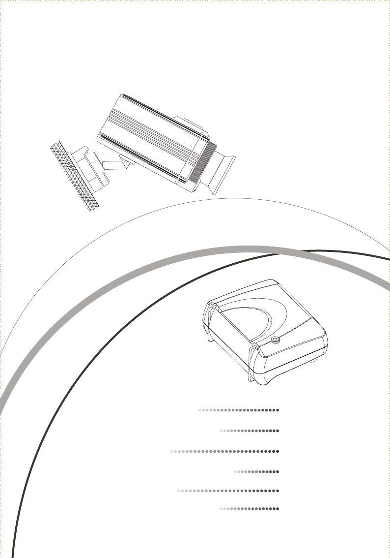
USER'S MANUAL
SURVEILLANCE SYSTEM
2.4 G z WIRELESS
H
. INTRODUCTION
1. INTRODUCTION
. PACKAGE CONTENTS
2. PACKAGE CONTENTS
. CONTROLS
3. CONTROLS
. SYSTEM INSTALLATION
4. SYSTEM INSTALLATION
. OPERATION
5. OPERATION
. TROUBLE SHOOTING
6. TROUBLE SHOOTING 9
4
5
6
8
1
CAUTION
RISK OF ELECTRONIC
SHOCK DO NOT OPEN
CAUTION:
DO NOT REMOVE THE COVER FOR REDUCING THE RISK OF ELECTRIC SHOCK.
NO USER-SERVICEABLE PARTS INSIDE REFER SERVICING TO QUALIFIED SERVICE PERSONNEL.
GENERAL SAFETY SUMMARY
WARNING
To prevent fire or shock hazard , do not expose the unit to rain or moisture.
IMPORTANT SAFETY INSTRUCTIONS
All the safety and operating instructions should be read before the product is operated.
The safety and operating instructions should be retained for future reference.
All warnings on the product and in the operating instructions should be adhered to.
All operating and use instructions should be followed.
Unplug this products from the wall outlet before cleaning. Do not use liquid cleaners
or aerosol cleaners. Use a damp cloth for the cleaning.
Do not use attachments not recommended by the products manufacturer if they may
cause hazards.
Do not use this product near water - for example, near a bath tub, wash bowl, kitchen
sink, or laundry tub, in a wet basement, or near a swimming pool; and the like.
Any mounting of the product should follow the manufacturer's instructions, and should
use a mounting accessory recommended by the manufacturer.
.
This product should be operated only from the type of power source indicated on the
marking label. If you are not sure of the type or power supply to your home, consult your
product dealer or local Power Company. For products intended to operate from battery
power, or other sources, refer to the operating instruction.
.
Power supply cord should be routed so that they are not likely to be walked on or pinched
by items placed upon or against them, paying particular attention to cords at plugs, or
other sources, refer to the operating instructions.
1.
2.
5.
3.
4.
6.
7.
8.
9.
10.
Do not overload wall outlets, extension cords, or integral convenience receptacles as this
can result in a risk of fire or electric shock.
Unplug this product from the wall outlet and refer servicing to qualified service personnel
under the following conditions.
When the power- supply cord or plug is damaged.
If liquid have been spilled, or objects have fallen into the products
Never push objects of any kind into this product through openings as they may touch
dangerous voltage points or short-out parts that could result in a fire or electronic shock.
Never spill liquid of any kind on the product.
12.
13.
14.
When replacement parts are required, be sure the service technician has used replacement
parts specified by the manufacturer or that have the same characteristics as the original part.
Unauthorized substitutions may result in fire, electric shock, or other hazards.
Upon completion of any service or repair to this product ask the service technician to
perform safety checks to determine that the product is in proper operating condition.
The product should be situated away from heat sources such as radiators, heat registers,
stoves, or other products including amplifiers that produce heat.
15.
16.
17.
If the product does not operate normally by following the operating instructions, adjust only
those controls that are covered by the operating instructions as an improper adjustment of
other controls may result in damage and will often require extensive work by a qualified
technician to restore this product to its normal operation.
When the product exhibits a distinct change in performance - this indicates a need for service.
If the products has been dropped or damaged in any way.
For added protection for this product during a lightning storm, or it is left unattended and
unused for long periods of time, unplug it from the wall outlet and disconnect cable system.
This will prevent damage to the product due to lightning and powerline surges.
11.

Overview
The Wireless Surveillance System with CMOS/CCD Images and four
channels available is just as your baby sitter, home/camp guard and
company monitoring. Easy to install, unequalled quality and reliability
make you have delighted and secure life.
Features
High Resolution Color CMOS/CCD Camera( Optional )
Range up to 300 feet (L. O. S )
Baby / Medical care monitor
Easy installation
1
1. INTRODUCTION
4 channels selectable
Weather Proof
Built-In Microphone for Audio Monitoring
Outdoor and home surveillance system
Building and office surveillance system
Video camera recording purpose (connected to VCR)
Operating frequency of ISM band 2.4 - 2.4835 G z
H
Applications
High Performance Audio/Video Receiver
Antenna embedded
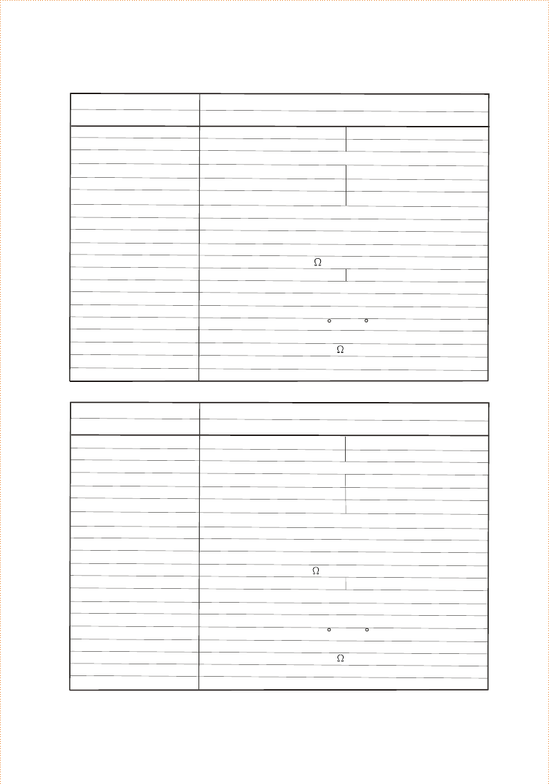
Specifications
2
Synchronize
Resolution
Min. Illumination
S/N Ratio
Video Input
Auto Electronic Exposure
Auto White Balance
Supply Voltage
Power Consumption
Operation Environment
Lens (Optional)
Audio Input
Weight
Size
2:1 Interlace
NTSC
1/3" CMOS Image Sensor
510 (H) X 492 (V)
15750 Hz
60 Hz
Wireless Camera - CMOS
Specification
2:1 Interlace
PAL
628 (H) X 582 (V)
15625 Hz
50 Hz
Internal
More Than 300 TV Lines
3 LUX (F1.2)
More Than 45 dB (AGC OFF)
1.0 Vpp / 75 composite Video signal
Auto
9V
120 mA
-15 C ~ + 55 C
F3.6 mm, F2.0 (Fix Board Lens)
1.0Vpp / 600 load for Mono
Approximate 160g
116 L x 45W x 52.5H (mm)
Model
Characteristic
Scanning System
Image Sensor
Efficiency Pixels
Horizontal Scan Frequency
Vertical Scan Frequency
1/60 ~ 1/2000 1/50 ~ 1/2000Sec.
Sec.
Synchronize
Resolution
Min. Illumination
S/N Ratio
Video Input
Auto Electronic Exposure
Auto White Balance
Supply Voltage
Power Consumption
Operation Environment
Lens (Optional)
Audio Input
Weight
Size
2:1 Interlace
NTSC
1/4" CCD Image Sensor
512 (H) X 492 (V)
15750 Hz
60 Hz
Wireless Camera - CCD
Specification
2:1 Interlace
PAL
512 (H) X 582 (V)
15625 Hz
50 Hz
Internal
More Than 420TV Lines
0.3 LUX (F1.2)
More Than 48 dB (AGC OFF)
1.0 Vpp / 75 composite Video signal
Auto
9V
200 mA
-15 C ~ + 55 C
F3.6 mm, F2.0 (Fix Board Lens)
1.0Vpp / 600 load for Mono
Approximate 160g
116 L x 45W x 52.5H (mm)
Model
Characteristic
Scanning System
Image Sensor
Efficiency Pixels
Horizontal Scan Frequency
Vertical Scan Frequency
1/60 ~ 1/10000 1/50 ~ 1/10000
Sec. Sec.
3
To provide the latest technologies product to our customer is our responsibility; therefore, we
reserve the right to change the specifications without prior notice.
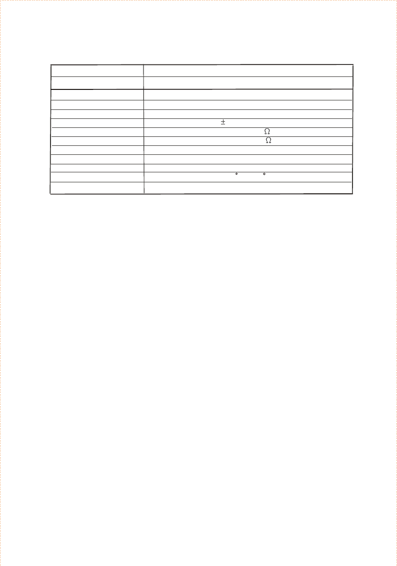
Frequency
Receiver Sensitivity
Channel Number
L.O. Stability
Video Output Level
Audio Output Level
Supply Voltage
Power Consumption
Antenna
Operation
Dimension
Environment
2400 MHz ~ 2483 MHz
-90 dBm (min.)
4 (2414,2432,2450,2468 MHz)
100 KHz (typ.)
1Vpp / 75
1Vpp / 600
9V
200mA (typ.)
Embedded
-15 C ~ +55 C
83 W x 70 H x 42L (mm)
Receiver
Specification
Model
Characteristic
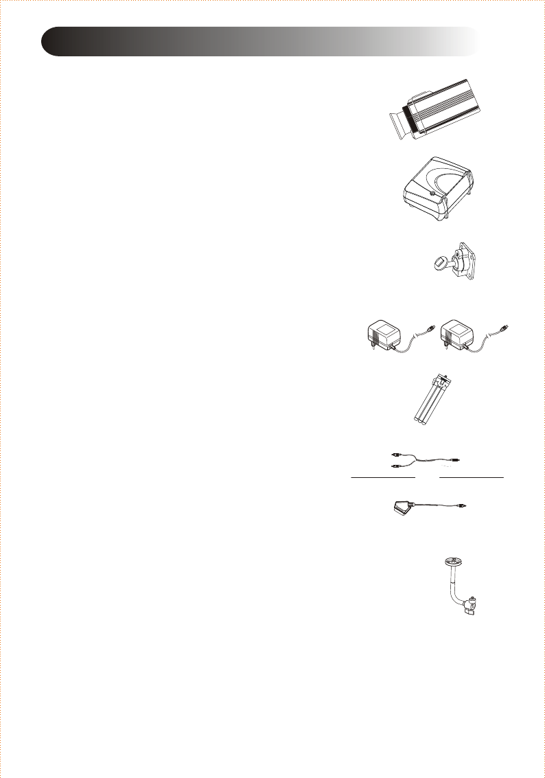
One unit of Wireless Camera
The Wireless Camera emits Audio and Video signals
over 2.4G z radio frequency carrier.
One unit of Receiver
The Receiver receives 2.4G z wireless Audio and
Video signals from the Wireless Camera.
One unit of Wall Mounting Bracket
The wall mounting bracket is used to bolster up the
Wireless Camera on the wall.
2. PACKAGE CONTENTS
Two units of Power Adaptor
Two power adaptors supply +9V(300mA) DC
power to the Wireless Camera and the Receiver.
One unit of Ceiling Mounting (Optional)
The ceiling mounting bracket is used to bolster
up the Wireless Camera.
One unit of Tripod
The tripod is used to bolster up the Wireless Camera.
One unit of RCA/SCART Cable
The RCA/SCART cable is used to connect the
Receiver to your A/V displays.
A/V displays: computer monitor (converted card
required), powered speakers, TV monitor etc.
Note: If any accessories listed above are missing, please contact the
sales representative where you purchase the Wireless Surveillance
System.
4
H
H
2RCA to phone plug
OR
SCART to phone plug
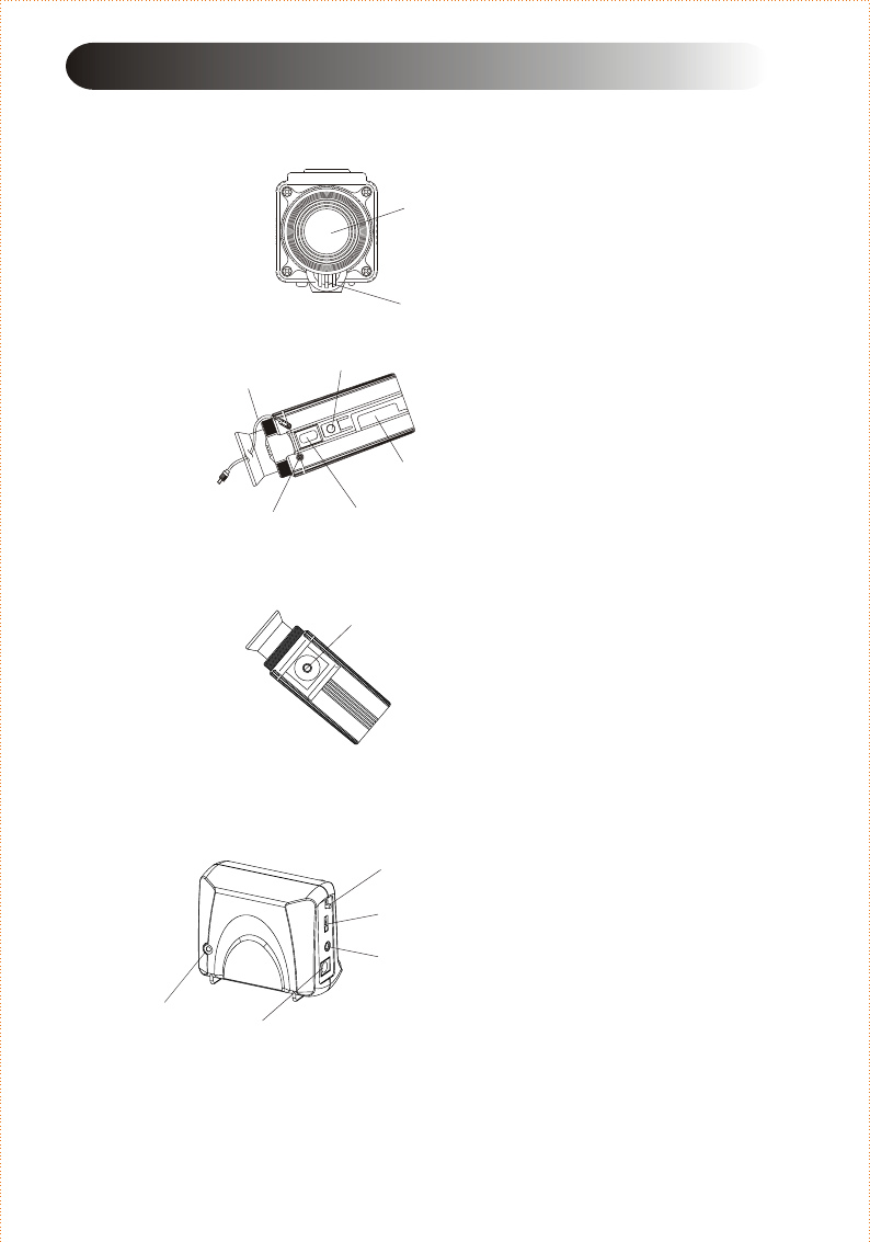
Wireless Camera
8. Ceiling Mounting Screw Nut
1. Lens
2. Microphone
3. Channel Rubber
4. Tripod Screw Nut
( Ceiling Mounting Screw Nut)
5. Power Cable
6. Power Indication LED
7. Wall Mounting Slide
Front
Bottom
Top
3. CONTROLS
5
Receiver
Front & Side
1. Power Switch
2. Channel Selector
3. AV Connector
4. Adaptor Connector
5. Power Indication LED
6
22
11
33
44
55
77
1
2
3
4
5
8
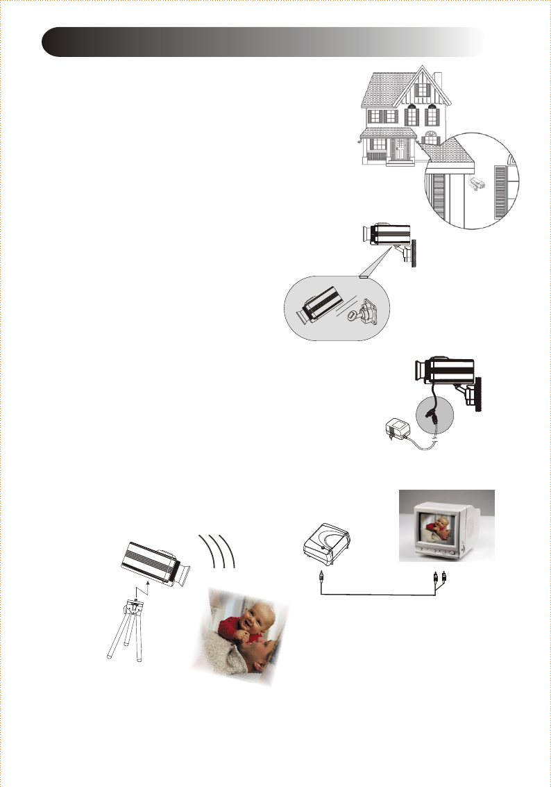
4. SYSTEM INSTALLATION
Wireless Camera
Connect Wireless Camera with the attached
adaptor; and plug the adaptor into the power
outlet.
Slide the Wireless Camera into the Wall
Mounting Bracket.
66
Fasten the Mounting Bracket on the wall or
ceiling (must under the roof).
6
Combine the Tripod and Wireless Camera to
assist parents in taking care of the baby.
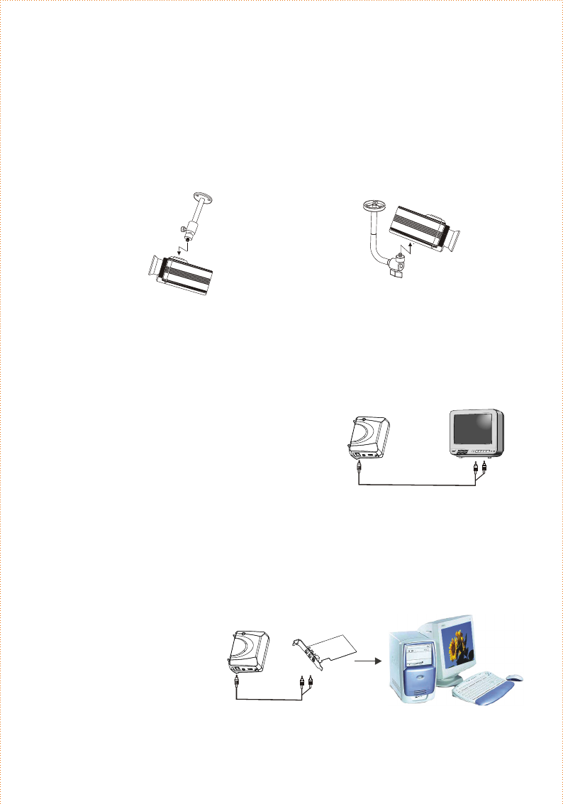
Receiver
Connect Receiver by phone plug to TV with
RCA Cable.
DC9V
A/V
1
ON
2
3
4CH
OFF
Connect Receiver by phone plug to PCI
Capture Card of PC with RCA Cable.
Plug Receiver into the power outlet with
attached adaptor.
Plug Receiver into the power outlet with
attached adaptor.
Phone plug to 2RCA/SCART connecting with TV
Phone plug to 2RCA connecting with PC
PCI Capture Card
DC9V
A/V
1
ON
2
3
4CH
OFF
Two ways to combine the Ceiling Mounting Bracket and Wireless Camera.
(Ceiling Mounting Bracket is selected.)
Screw the ceiling mounting
bracket into screw nut on top of
the wireless camera.
Screw the ceiling mounting
bracket into screw nut on bottom
of the wireless camera.
1. 2.
7

The power indication LED on Wireless Camera and Receiver will light up.
Note: The operation temperature is from -15 C ~ +55 C.
5. OPERATION
8
2.
3.
1. Turn on the Wireless Camera and Receiver.
Turn on A/V display.
4.
Wireless Surveillance System watches wherever you want.
5.
CH1 - CH1
CH2 - CH2
CH3 - CH3
CH4 - CH4
**
Check the channel of Receiver to be same as Camera.
( Camera set up to channel 1 originally. )
Switch the Receiver's Channel Selector to Ch1.
Image will show on A/V display if the channel of Wireless Camera and
Receiver is at the same one.
If no images or sound on A/V display, switch the Receiver's Channel
Selector to Ch2, 3 or 4; and check the images again.
If switching the channel of Wireless Camera is necessary, please refer to
page 10 - How to adjust the Channel Selector of Wireless Camera.

No Pictures or Sound
Power ON/OFF switch in right position.
Check all the cables well and rightly connected.
9
Receiver can not work properly when connecting
with PC
Check PCI capture card and software / driver installed correctly.
Make sure the surveillance system work properly if connecting with TV.
Check all the cables well and rightly connected when connecting with PC.
Check the channels of wireless camera and receiver at the same one.
Check the DC adaptors rightly connected.
6. TROUBLE SHOOTING
Please read this user's manual carefully before using the Wireless Surveillance
System. If you still have difficulties to use the Wireless Surveillance System
consult the following syndrome, which will guide you to solve most common
problems.
Interference in the Image and Sound
Move your Wireless Camera or Receiver slowly to find a best reception position.
Shorten the distance between your Camera and Receiver.
Check if there is any interference radio frequency source near your Receiver
source such as microwave oven or others 2.4 G z electronic products.
Switch channels of both Camera and Receiver to another channel;
e.g. from C 1 to CH3.
H
H

Warning : Changes or modifications to this unit not expressly approved by the party
responsible for compliance could void the user authority to operate the equipment.
This device complies with Part 15 of the FCC Rules. Operation is subject to the
following two conditions: (1) this device may not cause harmful interference, and
(2) this device must accept any interference received, including interference that
may cause undesired operation.
The user manual or instruction manual for an intentional or unintentional radiator
shall caution the user that changes or modifications not expressly approved by the
party responsible for compliance could void the user's authority to operate the
equipment.
How to adjust the Channel Selector of Wireless
Camera
Ch1
Ch2
Ch3
Ch4
Use a tool to open the channel rubber.
Switch inside selector by the tool to adjust the channel you want to set.
10

Version 1.0
M
E
T
S
Y
S
E
C
N
A
L
L
I
E
V
R
U
S
s
s
e
l
e
r
i
W
z
G
4
.
2
H
ELANsat Technologies USA
1813E. Dyer Rd. Unit 403
Santa Ana, CA 92705
TEL: (949) 851-1868
FAX: (949) 851-1808
E-mail: usa@elansat.com
sales @ samsonic.com