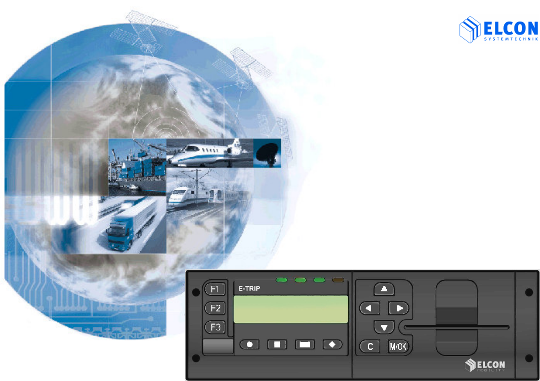
ELCON Systemtechnik 6600 E-TRIP ® 6600 User Manual OPERATING MANUAL E TRIP 9502
ELCON Systemtechnik GmbH E-TRIP ® 6600 OPERATING MANUAL E TRIP 9502
Contents
- 1. Mounting Manual
- 2. Operating Manual
Operating Manual
Version: 2004/08/16 Order No.: 9502 © ELCON Systemtechnik GmbH http://www.elcon-system.de
E
E-
-T
TR
RI
IP
P
®
®
Onboard Computer
for Fleet Management
Operating Manual

IMPORTANT NOTES
E-TRIP ® Version: 2004/08/16 Order No.: 9502 Page 2
Preface
Dear customer:
ELCON Systemtechnik GmbH would like to thank you
for your confidence in purchasing the onboard
computer E-TRIP®.
Please be sure to read this user manual carefully,
before you bring the unit into service !
Familiarize yourself with the operation and functions of
E-TRIP®.
Keep the user manual and other descriptive
documentation for your reference.
Should you still have questions not covered by
this manual, our service partner will be happy
to help you.
This user manual is subject to changes.
Copyright Notice
© Copyright by ELCON Systemtechnik GmbH. All
rights reserved.
This document and its contents shall not be reproduced
or transferred in any form without express permission.
Compensation will be claimed for any infringement.
Printed in Germany
Trademarks
E-TRIP® is a registered trademark of ELCON.
ORBCOMM® is a registered trademark of ORBCOMM
All other product names are trademarks or registered
trademarks of their respective owners.

IMPORTANT NOTES
E-TRIP ® Version: 2004/08/16 Order No.: 9502 Page 3
BE CAREFUL
Please read for your safety
Safety on the Road
Operating the unit when driving is not
allowed !
Make sure you know how to operate E-TRIP®
and use its functions prior to starting your trip.
Certain functions that require your full attention
are not accessible when the vehicle is moving.
You can read the vehicle's operational data such
as the oil temperature and oil pressure on the
display when driving.
While reading the display, pay sufficient
attention to the road traffic.
Use E-TRIP® only in the pre-determined way.
Do not open the E-TRIP® and do not put any
foreign objects into the equipment.
STATEMENTS
1. Statement according to FCC part 15.19:
This device complies with Part 15 of the FCC Rules.
Operation is subject to the following two conditions:
(1) this device may not cause harmful interference,
and (2) this device must accept any interference
received, including interference that may cause
undesired operation.
2. Statement according to FCC part 15.21:
Modifications not expressly approved by this
company could void the user's authority to operate
the equipment.
3. Statement according to FCC part 15.105:
NOTE: This equipment has been tested and found
to comply with the limits for a Class B digital device,
pursuant to Part 15 of the FCC Rules. These limits
IMPORTANT NOTE
Make sure that the smart card never
remains in a hot vehicle !

IMPORTANT NOTES
E-TRIP ® Version: 2004/08/16 Order No.: 9502 Page 4
are designed to provide reasonable protection
against harmful interference in a residential
installation. This equipment generates, uses and
can radiate radio frequency energy and, if not
installed and used in accordance with the
instructions, may cause harmful interference to
radio communications. However, there is no
guarantee that interference will not occur in a
particular installation. If this equipment does
cause harmful interference to radio or television
reception, which can be determined by turning the
equipment off and on, the user is encouraged to
try to correct the interference by one or more of
the following measures:
Reorient or relocate the receiving antenna.
Increase the separation between the equip-
ment and receiver.
Connect the equipment into an outlet on a
circuit different from that to which the receiver
is connected.
Consult the dealer or an experienced radio/TV
technician for help.
4. RF Exposure mobile:
The external antennas used for this mobile
transmitter must provide a separation distance of
at least 20 cm from all persons and must not be
co-located or operating in conjunction with any
other antenna or transmitter.
5. Statement according to road safety:
The use of the function ARO (Auxiliary Relay
Output) of the E-TRIP® is not permissible in the
member countries of the Economic Commission for
Europe (ECE) to control the engine. It is not
permitted, with the help of relay functions, to
influence the control of engine management or to
influence other functions affecting vehicle or road
safety, in vehicles participating in public transport.

IMPORTANT NOTES
E-TRIP ® Version: 2004/08/16 Order No.: 9502 Page 5
INSTALLATION
E-TRIP® should only be installed by an
authorized service center !
Special Note
The maximum output power of the PSRR
transmitter is 100 mW. Though this is a low
power level, a minimum distance of 20 cm
from the enclosure of the PSRR antenna to
all persons must be kept.
Special Note
Using GSM functionality within
North America, ONLY 1900MHz is allowed.
Antennas
For the installation of the antennas for E-TRIP® only the
following two antennas are permissible:
1) AEB 2400 for PSRR (DECT)
Technical Data:
Frequencies: 2.1/2.8 GHz UMTS-BLUETOOTH
Impedance: 50 Ohms
Gain: 2.65 dBi
2) MCA 18 90 STRIPE for GSM
Technical Data:
Frequency range:
AMPS: 824 - 894 MHz
GSM 900: 880 - 960 MHz
GSM 1800: 1710 - 1880 MHz
GSM 1900: 1850 – 1990 MHz
Impedance: 50 Ohms
Gain: 2.1 dBi

TABLE OF CONTENTS
E-TRIP ® Version: 2004/08/16 Order No.: 9502 Page 6
STATEMENTS..........................................................3
INSTALLATION........................................................5
ANTENNAS..............................................................5
1 INTRODUCTION....................................................7
1.1 System architecture and components .................7
1.2 Functions ............................................................8
2 INSTALLATION.....................................................9
2.1 Maintenance........................................................9
3 GETTING STARTED ...........................................10
3.1 Operating Keys .................................................10
3.2 LED´s................................................................11
3.3 Bringing into service..........................................11
3.4 Configuring the System Card ............................11
3.5 Preparing E-TRIP®............................................12
3.6 Input PIN...........................................................13
3.7 Driver ID............................................................13
3.8 Trip Start and Trip End....................................14
4 WORKING WITH E-TRIP®...................................15
4.1 Displaying Information.......................................16
4.2 E-TRIP® Setup...................................................22
4.3 Shortcut Menus .................................................23
4.4 Main Menu ........................................................24
4.4.1 Menu: Functions.............................................24
4.4.2 Menu: Services ..............................................35
4.4.3 Menu: Infos ....................................................44
4.5 Input of Values ..................................................48
4.5.1 Numerical Values ...........................................48
4.5.2 Reset the Input Value to Zero.........................48
4.6 System Warnings and Error Messages .............48
5 APPENDICES......................................................50
5.1 Menu Structure..................................................50
5.2 Symbols and Symbol Combinations ..................52
5.3 Error Codes.......................................................53
5.4 LED Codes........................................................56
5.5 Abbreviations ....................................................57
6 TECHNICAL DATA..............................................58
6.1 Dimensions .......................................................58
6.2 Environmental Data...........................................58
6.3 Electrical Data...................................................59
6.4 Standards..........................................................59
7 INDEX..................................................................60
8 LIST OF FIGURES...............................................62
9 AGENCY INFORMATION....................................66
10 DEALERS..........................................................67

1. INTRODUCTION
E-TRIP ® Version: 2004/08/16 Order No.: 9502 Page 7
1 INTRODUCTION
E-TRIP® is a high-performance onboard computer for
motor vehicles such as trucks, buses or cars. Having
the size of a car radio, the onboard unit collects vehicle
operation data, driver and environmental data and
transfers them to the fleet via GSM (Global System for
Mobile Communications, SMS - Short Message
Service). It supports all administration tasks occurring in
a modern fleet and is a basic part of a digital fleet
management system.
E-TRIP® may also serve the toll collection or work as
accident data recorder. The unit is able to display limit
and threshold values as well as indicate alarm
conditions.
E-TRIP® is a manipulation-safe unit. You are able to
analyze the fuel economy of your vehicle's fleet while
the driver can check the vehicle's operating data.
E-TRIP® has been designed as a modular unit. You can
configure the unit according to your individual
requirements.
1.1 System architecture and components
E-TRIP® comprises the following components:
• LCD (Liquid Crystal Display)
• Operation keys
• Signal generator
• LED´s
• GPS module
for the exact location and tracing of vehicles, RSE
(Road Side Equipment) is not required
• GSM (Global System for Mobile Communications)
module
for the data transfer through the mobile telephone
network
• PSRR module
• ORBCOMM module (option)
• E-TRIP Master – the E-TRIP® configuration program
that runs on the fleet PC
• System cards - one system card for the company -
supplied by your service center
• Driver cards - one driver card for each driver

1. INTRODUCTION
E-TRIP ® Version: 2004/08/16 Order No.: 9502 Page 8
1.2 Functions
Using the full range E-TRIP® allows:
• to log vehicle data, tracking data and environmental
data securely,
• to store these data securely,
• to transfer these data automatically and securely,
• to display data "driver-friendly", i.e. clearly and easily
legible,
• to check data, and
• to control engine, fuel consumption and efficiency.
LCD (Liquid Crystal Display): two lines, each of 16
characters length, for digital readouts, menu functions
and submenus, messages
Operation keys: for manual inputs, menu control,
operations.
Acoustic signals: to confirm correct operation actions
or signal errors.
RTC (Real-Time-Clock): battery-backed, for the correct
time information, switches between standard time and
daylight saving time (summer time).
GPS receiver: use of the GPS (Global Positioning
System) satellite signals for vehicle's positioning, either
upon request or at adjustable intervals.
PSRR: (Private Short Range Radio).The automatic data
transfer between the onboard unit and the dispatcher
can be realized in a short range (approximately 150 ft.).
Serial external interface: allows the connection of a
temperature sensor, for example in the loading space of
the vehicle.
SAE-J1708 interface: for collection of vehicle data
Acceleration and gyro sensors for three axles are
important if you would like to use E-TRIP® as accident
data recorder (future implementation).
Digital input 0/12 V: for storage and recall of the brake
block erosion by using the brake pedal
ARO (Auxiliary Relay Output): Customized relay function
to switch a relay via GSM.
It is not allowed to control the motor
management via this function!
Smart card reader: for startup, driver identification,
programming, service application.

2. INSTALLATION
E-TRIP ® Version: 2004/08/16 Order No.: 9502 Page 9
2 INSTALLATION
E-TRIP® is to be installed by service personnel of a
special workshop only. The correct connection and
first software installation as well as configuration are
reserved to specialists and mandatory for the proper
and fault-free function of the unit.
The location of installation is optional and can be
chosen according to your individual requirements.
Please ask your dealer for more information.
The detailed description of the installation is given in a
separate document. This document is available from
your vendor or service partner.
2.1 Maintenance
To clean the unit's front panel, use a clean cloth only. It
should be soft, dust-laying and antistatic. Don't apply
any cleaning agents in order to avoid damage of the
surface.
Special cleaning measures or procedures are not
required.
3. GETTING STARTED
E-TRIP ® Version: 2004/08/16 Order No.: 9502 Page 10
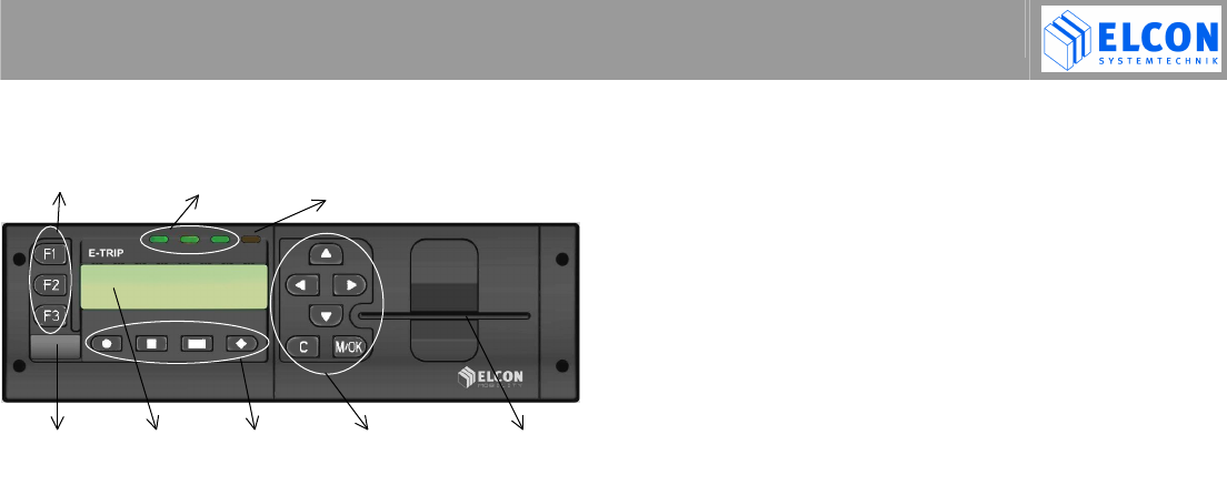
3 GETTING STARTED
figure 1 E-TRIP® and its operating and signal elements
3.1 Operating Keys
E-TRIP® has 13 operating keys as shown in figure 1.
Group 1: function keys
F1 Press F1 for at least 3 s to show the detailed
driver information.
F2 no function implemented
F3 no function implemented
Group 2: softkeys
softkey 1 softkey 2
softkey 3 ♦
♦♦
♦ softkey 4
Use the softkeys to operate the shortcut menus (see
chapter 4.3 ).
Group 3: control keys
cursor up cursor right
cursor down cursor left
Use these keys to scroll in menus, submenus, driver
information and to increment/decrement numerical
values.
C Escape/Clear
- Press shortly to switch to the previous menu level,
or
- to abort menu procedures, or
- for clearing entries.
M/OK Menu/OK
Press to
- switch on E-TRIP®, or
- invoke the main menu, or
- activate/confirm the menu selection, or
- save the values entered, or
- take over/confirm either the value selected or
entered.
Function keys Signal LED´ s Light sensor
Socket for LCD Softkeys Cursor and Smart card
service cable
control keys
reader slot

3. GETTING STARTED
E-TRIP ® Version: 2004/08/16 Order No.: 9502 Page 11
3.2 LED´s
Three tricolor – green, yellow and red – LED´s are
located above the display (figure 1). They indicate
system and error states by static and intermittent signals.
For the signals and their meanings please refer to
chapter 5.4 .
3.3 Bringing into service
When purchasing your E-TRIP®, you will receive several
smart cards – a driver card for each driver and one
system card. These cards need to be configured. To
start with the system card, an E-TRIP's individual range
of functions must be defined and released in the fleet PC
configuration program E-TRIP Master first and then in
E-TRIP® itself.
NOTE The system card is the key to your
system. Be sure to keep it in a safe place.
3.4 Configuring the System Card
To configure your system card with E-TRIP Master on
your fleet PC, follow these steps:
1. Create a set of vehicle data containing the PSRR
parameters as listed on the supplemental sheet you
received together with your E-TRIP®.
2. Using the menu function Save Database, write all
vehicle data sets you have created onto the system
card.
3. Remove the configured system card from the smart
card reader and proceed with chapter 3.5 .

3. GETTING STARTED
E-TRIP ® Version: 2004/08/16 Order No.: 9502 Page 12
3.5 Preparing E-TRIP®
E-TRIP® must now be registered at the fleet PC. The
vehicle can be outside the radio range of the PSRR
office modem as no connection to the fleet PC is being
built up during this offline subscription. You need the
configured system card and E-TRIP® will read the data
from the vehicle data set automatically when you carry
out the following steps:
1. Turn on the vehicle's ignition to activate E-TRIP®.
2. Follow the instruction on the display and insert the
system card into the smart card reader slot of the
unit on the right hand side (see figure 1).
E-TRIP® will read the PSRR parameters both from
the system card and from the built-in PSRR
module. If they fit together, it will log-in to the fleet's
PSRR office modem. Should the unit, however, be
unable to read the data set, it will first produce an
error code (see chapter 5.3 on page 53) on the
display and then, the display text will ask you once
more to insert the system card and again to
attempt the fleet log-in.
The successful log-in will be confirmed on the
display as shown in figure 73 on page 45. See also
4.4.2 .
3. Now, remove the system card.
The connection to the fleet PC will now be
established provided that the aerial of the PSRR
office modem is situated within the vehicle's radio
range.
4. Connect E-TRIP® to a portable PC using the service
cable and the socket on the lower left hand side of
the unit (figure 1).
5. Start E-TRIP Master on your PC.
6. Download the configuration data from the PC to
E-TRIP®.
The display will then welcome you as shown
in figure 2.
figure 2 welcome screen
Should you have turned on E-TRIP® for the very first time
after downloading the application software, the display will
read as in figure 3 (left). In case you have downloaded a
new application, the display will read as in figure 3 (right).
3. GETTING STARTED
E-TRIP ® Version: 2004/08/16 Order No.: 9502 Page 13
figure 3 screen after first download of application and
after download of new application
All user settings will be adjusted to the default values.
The configuration is then finished and E-TRIP® is ready
to serve you !
3.6 Input PIN
Should you have no valid driver card when starting your
trip, you must enter the PIN manually. This may also be
necessary when you want to operate the E-TRIP® after
the ARO (Auxiliary Relay Output) signal was sent to lock
the ARO relay. This is relevant for equipment with a
GSM module. To avoid manipulation, the PIN should be
dynamic.
• Enter the PIN (up to 8 numerical characters) using all
four cursor keys (see chapter 4.5.1 ).
• Confirm your entry with M/OK.
!"#$%
figure 4 input PIN
Should you need to enter your PIN because you had no
driver card, you need to enter your driver ID as well (see
chapter 3.7 ).
Once E-TRIP® has accepted your entries, the ARO relay
is ready to operate!
3.7 Driver ID
If no driver card is inserted, the display text will ask you to
enter your driver ID (up to 8 alphanumerical characters).
&'()('
*+##
figure 5 input driver ID
• Enter your ID as described in chapter 4.5 .
3. GETTING STARTED
E-TRIP ® Version: 2004/08/16 Order No.: 9502 Page 14
3.8 Trip Start and Trip End
There is no need to enter the beginning of a trip.
E-TRIP® will register the trip start automatically if there is
no trip start registered after you have switched on the
ignition. This is possible only after you have inserted
your driver card or after you have entered the PIN
together with your driver ID. Therefore, E-TRIP® can
store your driver ID in conjunction with the time.
If you want to enter the end of your trip, you can use
either the shortcut menu (see chapter 4.3 ) or go through
the menu structure.
(
#",#-!-
figure 6 input trip end
When the function is selected, the display will show the
current time and date to be stored for the end of the trip.
• Invoke the menu:
Functions Driving Times.. Trip End
and
• Press M/OK to acknowledge time and date.
The display shows stored.
• If you don't want to enter the trip end time, press C to
abort the entry.
Once you have entered the trip end, the data is written to
your driver card. Only then the LED on the left hand side
will signal (0.5 Hz intermittent, green) you to remove your
card.
((
""#-!-
figure 7 input trip start

4. WORKING WITH E-TRIP®
E-TRIP ® Version: 2004/08/16 Order No.: 9502 Page 15
4 WORKING WITH E-TRIP®
E-TRIP® can be switched on by one of these actions:
• Turn on the vehicle's ignition, or
• turn on the vehicle's lights, or
• press M/OK, or
• wheel pulses are available at input B1, or
• the automatic acquisition of measuring values or a
programmed alarm have been released through RTC.
Once you have turned on E-TRIP®, it will check whether
an authorization to use the vehicle is available. This is
the case as soon as you have inserted your driver card
into the smart card reader slot of the unit. If your driver
card is not available, you must enter the PIN to unlock
the ARO relay instead (see chapter 3.6 ). In case no Trip
Start was registered in E-TRIP®, enter your driver ID
once (see 3.7 ). E-TRIP® will store this driver ID until Trip
End is entered.
Initial Display
Once E-TRIP® has logged-in successfully (see chapter
3.5 ), the display shows the local time and date on the first
line and
• either the speed provided that E-TRIP® is being used
first time,
• or the driver's information displayed when E-TRIP® was
used last
as well as the card status on the second line as in figure
8. Date and time can be set through the configuration
program.
In case that E-TRIP® has not completed the proper shut-
down procedure when turned off last time, the error code
8 will be displayed. As the file system could be damaged,
please contact your service partner if this occurs. For
error codes, please read chapter 5.3 on page 53.
!"-!.#.-
(((
-/0
%
figure 8 initial display: successful and with error

4. WORKING WITH E-TRIP®
E-TRIP ® Version: 2004/08/16 Order No.: 9502 Page 16
Smart Card Status
A driver card or a system card may have different states
that are reflected in the card status symbol on the right
hand side of the second display line. For card states
please refer to chapter 5.2 .
figure 9 Smart card status
4.1 Displaying Information
In the initial state E-TRIP® shows, depending upon
configuration, up to 10 driver parameters. This driver
information is indicated with the following sign
.
Mileage Counter
Speed
Average Speed
Trip Odometer
Length of Trip
Fuel Consumption
Temperature
Status Display (Digital Input)
GPS Data
Vehicle Operation Data
Driver information is displayed on the left hand side of the
second line of the display. In the first line time and date
are displayed in nearly all driver information displays.
Press F1 to display the complete information for approx.
3 s.
4. WORKING WITH E-TRIP®
E-TRIP ® Version: 2004/08/16 Order No.: 9502 Page 17
Mileage Counter
The mileage value is displayed either in km or ML
(miles). Select the desired unit either during the
configuration (checkbox Miles, see E-TRIP - Master
manual) or through the E-TRIP® menu as explained in
chapter 4.4.2 )
!"#-!--
12
%--30
%--1
figure 10 mileage counter
Speed
The speed is displayed either in mph or km/h depending
on the setting in the configuration program (checkbox
mph, see E-TRIP SYSTEM MANUAL). You can adjust
the unit to your local requirements as described in
chapter 4.4.2 , Speed Unit.
!"#-!--
%-3./0
%-/
figure 11 speed
Average Speed
The average speed can be displayed either in mph or
km/h depending on the setting in the configuration
program (checkbox mph, see E-TRIP Master manual) or
through the E-TRIP®, see Mileage Counter.
!"#-!--
4)(2
∅$#,/0
∅$#,/
figure 12 average speed
It is possible to reset the average speed value to zero by
1. pressing C and
2. confirming the resulting display (figure 13) with
M/OK.
Should you rethink your decision and not want to reset the
value after step 1, press C once more. If you don't press
any key within 30 s after step 1, the average speed value
will not be reset and the previous information will be
shown.
4)(2
(0
figure 13 average speed, confirm reset
4. WORKING WITH E-TRIP®
E-TRIP ® Version: 2004/08/16 Order No.: 9502 Page 18
Trip Odometer
The daily distance is displayed either in km or in ML
depending on the setting in the configuration program
(checkbox mph, see E-TRIP System Manual). You can
adjust the unit to your local requirements as described in
chapter 4.4.2 . The highest value that can possibly be
displayed is 4294967.3 km or 2668841.9 ML.
!"#-!--
((
,,,,,,10
,,,,,,,,1
figure 14 trip odometer
It is possible to reset the trip odometer value to zero by
1. pressing C and
2. confirming the resulting display (figure 15) with
M/OK.
Should you rethink your decision and not want to reset
the value after step 1, press C once more. If you don't
press any key until 30 s after step 1, the value will not be
reset and the previous information will be shown.
((
(0
figure 15 trip odometer, confirm reset
Length of Trip
The display of “Length of Trip” is intended only for the
personal use of the driver. This time is independent of the
“Trip time”, which is calculated from Trip Start to Trip End.
“Length of Trip” is calculated only after switching on the
ignition.
The length of trip is displayed in hours.
!"#-!--
2/5(
"/0
"/
figure 16 length of trip
It is possible to reset the length of trip value to zero by
1. pressing C and
2. confirming the resulting display (figure 17) with
M/OK.
Should you rethink your decision and not want to reset the
value after step 1, press C once more. If you don't press
any key until 30 s from step 1, the value will not be reset
and the previous information will be shown.
2/5(
(0
figure 17 length of trip, confirm reset
4. WORKING WITH E-TRIP®
E-TRIP ® Version: 2004/08/16 Order No.: 9502 Page 19
Fuel Consumption
This information requires the connection of a J1708 bus
to E-TRIP®. The fuel consumption is displayed either in
l/100 km or L/h depending on the setting in the
configuration program (checkbox mph, see
E-TRIP System Manual).
6&&
6&&
%.--30
%./
figure 18 fuel consumption
Temperature
The display of the temperature, for example in the
loading space, is an option (see Cargo Temperature of
E-TRIP Service Tool). It requires E-TRIP® equipment
with a temperature sensor as well as this function to be
selected in the E-TRIP System Manual.
!"#-!--
(&(
%
0
%
figure 19 temperature
Use the control keys and to display the lowest and
highest temperatures measured since the display value
was last reset to zero.
1,#7
18$7
figure 20 minimum and maximum temperature values
It is possible to reset the temperature value to the actual
value by
1. pressing C and
2. confirming the resulting display with M/OK.
Should you rethink your decision and not want to reset the
value after step 1, press C once more. If you don't press
any key within 30 s from step 1, the value will not be reset
and the previous information will be shown.
Status Display (Digital Input)
The states of the two digital inputs available for your
individual use are shown here.
!"#-!--
'2&
-0
-
figure 21 status display (digital input)
The signals DIGIIN1 and DIGIIN2 used for this display
must be connected properly.
4. WORKING WITH E-TRIP®
E-TRIP ® Version: 2004/08/16 Order No.: 9502 Page 20
GPS Data
GPS data helps to show the vehicle's local position. The
display of GPS data requires E-TRIP®s equipment with a
GPS module as well as the configuration of this function
in E-TRIP Master. If E-TRIP® has no valid GPS data, the
display will show GPS: no signal. If, however, valid GPS
data are available, they will be displayed on one superior
and one subordinate display.
GPS Data, Superior Display
Line one contains the time and date while on line two
you find:
• the number of the satellites S that have been detected
(maximum 12 satellites),
• the quality Q of the GPS signal (maximum 9),
• the speed and the direction (cardinal point) which the
vehicle is moving to represented by one of eight
arrows (resolution of 45°).
!"-!.#.-
9'
:;"-/
:;"-/
figure 22 GPS data, superior display
If the vehicle does not move, a dot is displayed instead
of an arrow. An arrow pointing to the left means that the
vehicle moves towards East while an arrow pointing up
means that the vehicle moves towards North etc.
Press
to read the subordinate display.
GPS Data, Subordinate Display
Line 1 displays the latitude while the second line shows
the longitude of the vehicle's position.
° !’"#”
°!"’"#”
figure 23 GPS data, subordinate display
Press
to return to the superior display or F1 to display
the complete information text for approx. 3 s.
9&
92&
4. WORKING WITH E-TRIP®
E-TRIP ® Version: 2004/08/16 Order No.: 9502 Page 21
Vehicle Operation Data (SAE-J1708 Bus)
Vehicle operation data can be displayed provided that a
J1708 bus exists in the vehicle and is connected to
E-TRIP®. There are one superior and seven subordinate
displays as listed in the following.
Vehicle Operation Data, Superior Display
Date and time are displayed on line 1 while line 2 shows
the engine speed in revolutions per minute.
!"#-!--
2
---1
---1
figure 24 vehicle operation data, superior display,
engine speed
Use cursor keys and to display the vehicle data of
the subordinate displays.
Vehicle Operation Data, Subordinate Displays
( !"
<(
figure 25 vehicle operation data, oil pressure/boost
pressure
7
6&7
figure 26 vehicle operation data, oil temperature/fuel
temperature
1 7
4== !
figure 27 vehicle operation data, intake manifold
temperature/accelerator pedal
(&(
((
figure 28 vehicle operation data, cruise control
status/retarder status

4. WORKING WITH E-TRIP®
E-TRIP ® Version: 2004/08/16 Order No.: 9502 Page 22
6 .--3
46 .--3
figure 29 vehicle operation data, instantaneous fuel
economy/average fuel economy
(3<(3
figure 30 vehicle operation data, parking brake/speed
limiting status
&
<>
figure 31 vehicle operation data, PTO status/battery
potential
4.2 E-TRIP® Setup
When
• making your individual settings,
• entering driver data, and
• sending and receiving messages
E-TRIP® guides you through a hierarchical menu
structure. With three (currently) of the most frequently
used functions you can be also reached directly by
shortcuts (see next chapter). An overview of the complete
menu structure can be found in the appendix 5.1 .
Invoke E-TRIP®' s main menu by pressing M/OK.
• when in driver information mode and
• when the vehicle halts.
The menu will automatically shut as soon as the vehicle
starts moving.
The menus and menu items are arranged in sequences.
Use the cursor keys and to scroll in these
sequences. Press M/OK to select the desired menu item
or function. To end the current menu or menu item or
return to the previous menu level, press C. The menu
level is displayed on the upper right hand side of the
display. A line of hyphens indicates that you have reached
the last item of a menu. When you press you will jump
to the first menu item while when you press you will
return to the current menu.

4. WORKING WITH E-TRIP®
E-TRIP ® Version: 2004/08/16 Order No.: 9502 Page 23
4.3 Shortcut Menus
E-TRIP® has currently two shortcut menus to allow quick
access to pre-defined frequently used functions when in
driver information mode. The shortcut bars are invoked
through the softkeys underneath the display, i.e.,
• press
to open the first shortcut menu.
/(=&1&
?@?@? @?!@
figure 32 shortcut menu 1, menu level 1
• press
to open the second shortcut menu.
/(=&1&
?@?@? @?!@
figure 33 shortcut menu 2, menu level 1
• press
to open the third shortcut menu.
• press ♦
♦♦
♦ to open the fourth shortcut menu.
Using the softkeys of the shortcut menu 1, you will
invoke the following pre-defined functions:
key input of trip end, see page 26 and 14.
key input of driver activities selected from a pre-
defined list, see page 28.
key Text selection; sending message text
♦
♦♦
♦ key send emergency call through GSM (GSM
module must be installed)
Using the softkeys of the shortcut menu 2, you will
invoke the following pre-defined functions:
key input of “Refuel” data, see page 28.
key input of “Drivers Daily Log”, see page 25.
key not used
♦
♦♦
♦ key not used
The shortcut menus 3 and 4 have currently no function.

4. WORKING WITH E-TRIP®
E-TRIP ® Version: 2004/08/16 Order No.: 9502 Page 24
4.4 Main Menu
1&
6&=0
figure 34 main menu
Upon invoking the menu by pressing M/OK, its upper
level, i.e., the main menu, will appear first. Line one
displays the menu title while line two displays a menu
item.
Press to reach the next menu item or to select the
previous one. Once you have reached the end of the list
of menu items, a line of hyphens will be displayed. Press
to return to the first menu item.
To select a menu item, press M/OK. To return from a
submenu to its superior menu, press C. The current
menu level is displayed in the upper right corner of the
display. When you are on the first menu level, you can
shut the menu pressing C. When on a subordinate
menu level, press C to reach the next superior menu
level.
Pressing C and holding the key down at least 2 s will
shut the menu and E-TRIP® will return to the driver
information mode. This will also happen automatically if
no key is operated for approx. 20 s.
The following chapters will briefly present the menus and
their menu items (submenus and functions).
4.4.1 Menu: Functions
The functions menu contains menu items that can be
functions or submenus. Submenus are extended by two
dots at the end of the word. An overview of the functions
menu can be found in the appendix 5.1 .
Emergency Call
To send an emergency call via GSM or ORBCOMM ,
either press the softkey
and softkey ♦
♦♦
♦,
• or select the menu
Functions Emergency Call,
• and press M/OK if you want to send an emergency
call.
(2=
/?A@
figure 35 emergency call
Depending on the configuration, this message can be sent
to the following recipients:
- Fleet Manager
- Emergency Call recipient (Mobile Phone)

4. WORKING WITH E-TRIP®
E-TRIP ® Version: 2004/08/16 Order No.: 9502 Page 25
Drivers Log
E-TRIP® records the data for the drivers daily log for at
least two consecutive days. More days are possible, but
cannot be guaranteed. The total number which were
stored by E-TRIP® can be read in the lower right corner
of the display. In the example of figure 36 the total
number is 2. The number in front of the total number is
index of the actual selected day, shown in the lower left
corner.
The displaying of the Drivers Log data is effected on two
differently formatted screens the summary data screen
and the detailed data screen. The first indicated screen
shows the data, which for the vehicle and the driver were
stored by E-TRIP®, see figure 36. The detailed data
screen displays data to the Duty Status of the driver, see
figure 37. Press ♦
♦♦
♦ (softkey 4) in order to change
between screens.
Note:
There are two automatic change-overs, which are made
by E-TRIP®.
If the vehicle drives off, E-TRIP® switches
automatically to DRIVING.
E-TRIP® switches automatically from DRIVING to
ON DUTY,
if the ignition is switched off
or
if PTO is active and the vehicle is not moving.
If a new duty status is entered within one minute after
the automatic change from DRIVING to ON DUTY, the
automatic change is ignored and only the manually
entered status is stored by E-TRIP® .
To display the drivers log, either press
(softkey 2) twice,
• or select the menu
Functions Drivers Log.
'()(2
-,.!.- ?.@
figure 36 displaying drivers log
4. WORKING WITH E-TRIP®
E-TRIP ® Version: 2004/08/16 Order No.: 9502 Page 26
After the call of the function “Drivers Log” the current
date is indicated, see figure 36. When displaying the
Drivers Log data two display modes are available.
• use
and
for next and previous screen of
summary data.
The following screens are available:
1) Date
2) Total distance of the vehicle in miles or kilometers.
3) Driver ID
4) Driven distance today of driver shown in
“Driver ID”.
5) Duration 1: OFF DUTY time
of the driver shown in “Driver ID”.
6) Duration 2: SLEEPER time
of the driver shown in “Driver ID”.
7) Duration 3: DRIVING time
of the driver shown in “Driver ID”.
8) Duration 4: ON DUTY time
of the driver shown in “Driver ID”.
• use to change to previous day.
• use to change to next day.
• use ♦
♦♦
♦ (softkey 4) to change between summary data
and detailed data screen.
• Press C to abort displaying Drivers Log.
Change to the detailed data screen, to transfer drivers
duty status into blank logs, see figure 37.
On detailed data screen, the following data is indicated:
1) upper left: date
2) upper right: [actual index / maximum index]
3) lower left: duty status start time
4) lower right: duty status
-,. ?.%@
----
figure 37 duty status of drivers
log
• use to change to previous day.
• use to change to next day.
• use ♦
♦♦
♦ (softkey 4) to change between detailed data and
summary data screen.
• Press C to abort displaying Drivers Log.
If there is ?
??
?
-.-
-.--.-
-.-
@
@@
@ indicates in the upper right corner of
the display, then no entries exist for the duty status for the
desired day, see figure 38.
-,.!?-.-@
----&3
figure 38 duty status
unknown
If the data of another driver is to be indicated, the
Driver ID of this driver must be entered or the driver card
inserted into the smard card reader slot, see chapter
Driver ID on page 27.

4. WORKING WITH E-TRIP®
E-TRIP ® Version: 2004/08/16 Order No.: 9502 Page 27
Driving Times
'()2
'()2
/((0
(0
figure 39 driving times: show trip start and trip end
The system calculates driving times when it has both the
start and the end of the trip. The trip start is recorded
automatically when you insert your driver card, however,
you need to enter the trip end manually.
• Select the menu
Functions Driving Times.
• For the input of trip start and trip end, refer to chapter
3.8 on page 14.
Driver ID
If a driver does not have his driver card available, the
driver can use the following function to input of his
Driver ID.
When ready for application,
• select the menu
Functions Driver ID,
• use
and
to select the appropriate character.
• use to set the cursor to the next position.
• use to delete the character left of the cursor.
• Press M/OK to enter it, or press C to abort the input.
'()('
figure 40 input of driver ID
4. WORKING WITH E-TRIP®
E-TRIP ® Version: 2004/08/16 Order No.: 9502 Page 28
Driver Activity
E-TRIP® can register driver activities and provide each
one with a time stamp. Prior to using this function, the
dispatcher needs to define an individual list of maximum
32 activities in E-TRIP Master and download the list
from the fleet PC to E-TRIP®. When ready for
application, either press softkey
, or
• select the menu
Functions Driver Activity,
• use
and
to select the appropriate activity text
from the menu.
It will be displayed on the second line of the display
while its number will be displayed on the first line in
the right corner.
• Press M/OK to enter it, or press C to abort the input.
'()(4=)
4=)?"@
8
B3
figure 41 driver activity
When purchasing your E-TRIP®, a number of pre-defined
driver activities will be delivered in E-TRIP Master. Feel
free to edit and extend the list. For the undefined
activities, a dummy will be displayed.
Refuel
E-TRIP® can store the data, which is necessary for the
calculation of fuel tax.
The input takes place in two steps.
1) Input of fuel quantity
2) Input of fuel costs
When ready for application, either press softkey
and
afterwards softkey , or
• select the menu
Functions Refuel,
• use
and
to select the appropriate digits,
• use to set the cursor to the next position,
• use to delete the character left of the cursor,
• use ♦
♦♦
♦ (softkey 4) to change to the desired unit.
• Press M/OK to enter the appropriate value, or
• press C to abort the input.
5&
5&
-----2B
-----BC
figure 42 refuel

4. WORKING WITH E-TRIP®
E-TRIP ® Version: 2004/08/16 Order No.: 9502 Page 29
4.4.1.1 Messages (Option)
The messages functions require the equipment of
E-TRIP® with a GSM or ORBCOMM module. For an
overview of the menu, please refer to the appendix 5.1 .
Outgoing Message
The outgoing list contains the last five messages, which
could not be sent by E-TRIP® via command Text
selection (see Text selection on page 30).
12
&22"
figure 43 Incoming message, menu
• Select the menu
Functions Messages.. Outgoing 5
The number following the menu command Outgoing
indicates the number of messages in the outgoing list.
• To scroll in the list of outgoing messages (see figure
44), use and
.
The display will show date/time message and the text
number in the upper right corner.
NOTE: The time is indicated in 24-hour format.
The maximum number of outgoing messages is 5.
&22?@
&22?@
-!.#.- #--
-!.#.- # -
figure 44 Outgoing message, base screen
• Press softkey
to send the indicated message
via GSM.
• Press softkey
to send the indicated message
via ORBCOMM.
• To display information about the recipient, use .
&22?@
&22?@
612(
(2=(=
If the recipient is a predefined phone number, either
Fleet Manager or Emerg.call reci. is
indicated.
• Use to switch back to show date/time.
• To select a message and read its text, press M/OK
(see figure 45). The text will appear on line 2.
• Press C to return to the messages menu, or
press C and hold it down for at least 2 s to return to the
driver information mode.
4. WORKING WITH E-TRIP®
E-TRIP ® Version: 2004/08/16 Order No.: 9502 Page 30
-!.#$%
-!.#$%
+:=
:=
figure 45 Outgoing message, message text
• To scroll to the next or previous word of the text to
read the complete message, use or
• Press to jump to the end of the message and to
jump to its beginning.
• Press M/OK to switch back to base screen (see figure
44).
• Press C to return to the previous display, or
press C and hold it down for at least 2 s to return to
the driver information mode.
• Press to delete the displayed message.
12?@
0
figure 46 Outgoing message, message delete
Delete Message
Prior to deleting the message, E-TRIP® trip will ask you
(see figure 46) to confirm the deletion to avoid mistakes.
• Acknowledge the query with M/OK to finally delete the
message. E-TRIP® will remove it from the outgoing list.
• Press C to abort the deletion and return to the previous
display.
Text selection
To use this function, a list of 50 texts needs to be pre-
defined in E-TRIP Master. The maximum text length is
160 characters. The list is transferred to E-TRIP® either
via PSRR or downloaded through the service interface.
The lower line of the display is used for the message text.
Should the text exceed the length of 16 characters, use
and to scroll and read the complete text.
12?@
12?@
828
28
4. WORKING WITH E-TRIP®
E-TRIP ® Version: 2004/08/16 Order No.: 9502 Page 31
To send one of the predefined messages,
• select the text you would like to send from the list
using and .
• Press M/OK to acknowledge the selected message
and send it to a predefined phone number (see
Message Setup on page 44). If the text has not been
sent, an error message will be displayed and this
message is added to the outgoing list,
see Outgoing Message
The number of the text will be displayed on the first line
in the right corner. The arrow preceding the index points
into the direction you can scroll to display the rest of the
message should the text be too long to be displayed in
total.
[50]: All characters of the message No. 50 are
displayed.
[50]: The beginning of the message is displayed.
[50]: The end of the message is displayed.
[50]: Both the beginning and the end of the
message are not displayed.
12?"-@
=3:*
figure 47 Text selection, example
Incoming Message
You can receive messages via GSM or satellite
(ORBCOMM) and E-TRIP® will indicate this both
acoustically with a tone sequence and visually
on the display and by LED (see chapter 5.4 ).
---!.#.-
12
figure 48 Incoming message
• Select the menu
Functions Messages.. Incoming 2/1
12
=2.
figure 49 Incoming message, menu
The two numbers after the menu command Incoming
indicate the number of messages in the incoming list (first
value) and messages still being displayed or read (second
value).
• To scroll in the list of incoming messages (see figure
50), use and .
The display will show date/time message and the text
number in the upper right corner.
4. WORKING WITH E-TRIP®
E-TRIP ® Version: 2004/08/16 Order No.: 9502 Page 32
NOTE The time is indicated in 24-hour format
The maximum number of incoming
messages is 50.
=2?@
=2?@
-!.#.- #--
-!.#.- # -
figure 50 Incoming message, base screen
indicates that the message was not displayed or
read.
indicates that the message is still being displayed
or was read.
• To display information about the recipient, use .
=2?@
=2?@
612(
D"!,,
If the recipient is a predefined phone number, either
Fleet Manager or Emerg.call reci. is
indicated. If the phone number of the received
message is unknown, the phone number itself is
indicated.
• Use to switch back to show date/time.
• To select a message and read its text pressing M/OK
(figure 51).
• Press C to return to the messages menu, or
press C and hold it down for at least 2 s to return to the
driver information mode.
-!.#$%
-!.#$%
+:=
:=
figure 51 Incoming message, message text
• To scroll to the next or previous word of the text to read
the complete message, use or
• Press to jump to the end of the message and to
jump to its beginning.
• Press M/OK to switch back to base screen (see figure
50). The text will be legible on line 1.
• Press C to return to the previous display, or
press C and hold it down for at least 2 s to return to the
driver information mode.
• Press to delete the displayed message.
12?@
0
figure 52 Incoming message, message delete

4. WORKING WITH E-TRIP®
E-TRIP ® Version: 2004/08/16 Order No.: 9502 Page 33
Delete Message
Prior to deleting the message, E-TRIP® trip will ask you
(see figure 52) to confirm the deletion to avoid mistakes.
• Acknowledge the query with M/OK to finally delete the
message. E-TRIP® will remove it from the incoming
list.
• Press C to abort the deletion and return to the
previous display.
4.4.1.2 Warnings
The warnings of this menu pertain to speed, rpm and/or
temperature values. For an overview of the menu, please
turn to appendix 5.1 . Warnings are on the display for at
least 10 s or until you press a key. Press M/OK to
acknowledge a warning.
Speed exceeded
RPM value exceeded
""
""
)%"3./
!---1
""
)" /
figure 53 functions, alarms
Temperature exceeded
""
""
%-7
-7
You can define their limit values yourself. A limit value
must be higher than zero in order to release an alarm.
When delivered, E-TRIP®' s warnings are not defined, i.e.,
the limit values are zero.

4. WORKING WITH E-TRIP®
E-TRIP ® Version: 2004/08/16 Order No.: 9502 Page 34
Max. Speed
If you wish to receive a warning on the display and an
alarm warning tone when you have exceeded a speed
value, define the speed limit as follows:
• Select the menu
Functions Warnings.. Max.Speed.
• Enter a limit value (see chapter 4.5.1 ) greater than
zero.
• Activate/deactivate the warning using the softkey
below the LCD.
Max. Engine Speed
If you wish to receive an alarm on the display and a
warning tone when the engine has exceeded the RPM
value, define the RPM limit value as follows:
• Select the menu
Functions Warnings.. Max.EngineSpeed.
• Enter a limit value (see chapter 4.5.1 ) higher than
zero.
• Activate/deactivate the alarm using the softkey
below the LCD.
Max. Temperature
If you wish to receive a warning on the display and an
alarm tone when a certain temperature was exceeded, the
temperature value must be defined in the E-TRIP Master
and transferred to E-TRIP®.
18(&(
18(&(
%-7?66@
%-7?@
figure 54 functions, warnings, max. temperature
• Select the menu:
Functions Warnings.. Max. Temperature
• Enter a limit value (see chapter 4.5.1 ) within the range
from -99.9 to +99.9.
• Activate/deactivate the alarm using the softkey
below the LCD.
NOTE The temperature will be measured and
stored cyclically also when the alarm
function is deactivated.

4. WORKING WITH E-TRIP®
E-TRIP ® Version: 2004/08/16 Order No.: 9502 Page 35
Min. Temperature
If you wish to receive a warning on the display and an
alarm tone when the temperature has fallen below a set
limit, the temperature value must be defined in the
E-TRIP Master and transferred to E-TRIP®.
1(&(
1(&(
-7?66@
-7?@
figure 55 functions, warnings, min. temperature
• Select the menu:
Functions Warnings.. Min. Temperature
• Enter a limit value (see chapter 4.5.1 ) from the range
of -99.9 to +99.9.
• Activate/deactivate the alarm using the softkey
below the LCD.
NOTE The temperature will be also measured and
stored cyclically when the alarm function is
deactivated.
Alarm Time
This function enables you to set an alarm within a time
period of 24 hours. E-TRIP® will emit a signal tone at the
defined alarm time. This requires that the ignition is
switched off. Switching on the ignition will disable the set
alarm.
4((
- !"?@
figure 56 functions, alarm time
To set an alarm
• select the menu:
Functions Alarm Timer.
• Set the time.
• Activate/deactivate the alarm using the softkey
below the LCD.
4.4.2 Menu: Services
Please refer to appendix 5.1 for an overview of the menu
services.
4. WORKING WITH E-TRIP®
E-TRIP ® Version: 2004/08/16 Order No.: 9502 Page 36
4.4.2.1 Tones
In this menu, you are able to activate or deactivate the
alarm tones for the
• key click,
• acknowledge tone, and
• error tone
and set their volume level.
Volume
Here, you set the volume of system alarms (see chapter
4.6 ).
• Select the menu:
Services Tones.. Volume
• Use
to increase or
to decrease the volume of the
beeper.
Eight levels are possible. The value of zero will turn
off the beeper, i.e., E-TRIP® will not emit any acoustic
signal.
• Press M/OK to confirm the selected new volume.
• Press C to return to the previous volume level.
>&
E!
figure 57 services, tones, volume
Key click
E-TRIP® is delivered with the key click active, i.e., each
key pressure will be accompanied by an acoustic signal.
To deactivate or reactivate the key click,
• Invoke the menu:
Services Tones.. Key Click
• Use the cursor keys to select ON or OFF,
• or, press the softkey • underneath the LCD.
• Press M/OK to confirm and take over your selection.
A==3!
=)
figure 58 services, tones, key click
Acknowledge Tone
E-TRIP® is delivered with the acknowledge tone active,
i.e., each correct input will be accompanied by an acoustic
signal. To deactivate or reactivate the acknowledge tone
• select the menu:
Services Tones.. Acknowledge Tone
• Use the cursor keys to select ON or OFF.
• Press M/OK to confirm and take over your selection.
4=32
=)
figure 59 services, tones, acknowledge tone

4. WORKING WITH E-TRIP®
E-TRIP ® Version: 2004/08/16 Order No.: 9502 Page 37
Error Tone
E-TRIP® is delivered with the error tone active, i.e., each
wrong input will be accompanied by an acoustic signal.
To deactivate or reactivate the error tone
• select the menu:
Services Tones.. Error Tone
• Use the cursor keys to select ON or OFF,
• or, use the softkey • underneath the LCD.
• Press M/OK to confirm and take over your selection.
(((!
=)
figure 60 services, tones, error tone
4.4.2.2 Display
Please refer to appendix 5.1 for an overview of the
display menu.
Contrast
The contrast of the LCD is automatically adjusted through
a temperature sensor located close to the LCD. This
function, however, allows an adjustment of the basic
contrast value.
• Select the menu:
Services Display.. Contrast
• Use
to increase and
to decrease the contrast to
one of the 10 possible values.
• Press M/OK to confirm and take over your selection.
• Press C to return to the previous value.
(
E-
figure 61 services, display, contrast
4. WORKING WITH E-TRIP®
E-TRIP ® Version: 2004/08/16 Order No.: 9502 Page 38
Brightness
The LCD's brightness is automatically adjusted through a
light sensor located in the front panel of E-TRIP® above
the display. This menu function, however, allows you to
adjust the basic brightness value of the LCD's
background illumination.
• Select the menu:
Services Display.. Brightness
• Use
to increase and
to decrease the brightness
to one of the 20 possible values.
• Press M/OK to confirm and take over your selection.
• Press C to return to the previous value.
<(2/
E
figure 62 services, display, brightness
Distance Unit
This function allows you to adjust the unit of the distance
to the local unit.
• Select the menu:
Services Display.. Distance Unit.
• Use and to switch between km and ML.
• Press M/OK to confirm and take over your selection.
• Press C to return to the previous selection.
'=B
'=B
=)1
30
figure 63 services, display, distance unit
Speed Unit
This function allows you to adjust the unit of the speed to
the local unit.
• Select the menu:
Services Display.. Speed Unit.
• Use
or
to switch between km/h and mph.
• Press M/OK to confirm and take over your selection.
• Press C to return to the previous selection.
B
B
=)/
3./0
figure 64 services, display, unit speed
4. WORKING WITH E-TRIP®
E-TRIP ® Version: 2004/08/16 Order No.: 9502 Page 39
Temperature Unit
• Select the menu:
Services Display.. Unit Temp..
• This function allows you to adjust the unit of the
temperature to the local unit.
• Use and to switch between °C and °F.
• Press M/OK to confirm and take over your selection.
• Press C to return to the previous selection.
(&(B
(&(B
=)76
70
figure 65 services, display, temperature unit
Format Date/Time
To set the format of the date/time display to your
individual preferences,
• Select the menu:
Services Display.. Format Time/Date.
• Press to display the full format
hh:mm DD.MM.YYYY. When you
• press , the display will read active: hh:mm DD.
• By operating
or
you select between the two
formats.
• Press M/OK to confirm and take over your selection.
• Press C to return to the previous selection.
6(.'
6(.'
//11.''.FF
=)//
6(.'
//11.''.FF
figure 66 services,
display, format
4. WORKING WITH E-TRIP®
E-TRIP ® Version: 2004/08/16 Order No.: 9502 Page 40
Keyboard Brightness
To set the keyboard brightness of the keys to your
individual preferences,
• Select the menu:
Services Keyb.Brightness.
• By operating
or
you select a value between 0
and 20.
• Press M/OK to confirm and take over your selection.
• Press C to return to the previous selection.
4.4.2.3 Date/Time
Please refer to appendix 5.1 for an overview of the
date/time menu.
Adjustment
E-TRIP®'s time is automatically set through GPS. The
only thing necessary is to enter the time zone. This
menu is available only in service mode, i.e., a workshop
card must be inserted. Only then,
• you can select the menu:
Services Date/Time.. Adjustment
and
• adjust the GMT time.
4G&
4G&
""91
#-!--
figure 67 services, make settings, GMT time and date
You can change time and date without any limitation.
First, set the time and then the date by
• moving the cursor over the numbers and
• incrementing or decrementing it using and
• If you press C during the input, all changes will be
ignored and the input field will disappear.
• Press M/OK to confirm and take over the new
date/time settings.
Time Zone
In order to have your local time displayed, use this
function to select a time offset within the range -12:00 h to
+12:00 h. This value will be added to E-TRIP® GMT time.
H
91D---/
figure 68 services, date/time, time zone
Select the menu:
Services Date/Time.. Time Zone
4. WORKING WITH E-TRIP®
E-TRIP ® Version: 2004/08/16 Order No.: 9502 Page 41
Summer Time
If you want E-TRIP® to display updated summer time
settings, you need to activate this function. To do so,
• select the menu:
Services Date/Time.. Summer time.
&(
=)
figure 69 services, make settings, date/time, summer
time
E-TRIP® does this automatically, provided that the start
and end of summer time have been defined in
E-TRIP Master and downloaded to the unit before.
After the automatic switch to summer time, E-TRIP®
displays an information for about 5 s after you have
switched it on (figure 70).
&(
&(
=)
=)
figure 70 services, make settings, summer time
active/not active
GMT Time
To display (editing not possible) the GMT time
• select the menu:
Services Date/Time.. GMT Time
91
-,-!.#.--
figure 71 services, make settings, date/time, GMT time
Language
Texts can be displayed in several languages. The
language to be used can be pre-defined in
E-TRIP Master. If this is not the case, E-TRIP® will
automatically use English. You can select another
language from this menu. To do so,
• invoke the menu: Services Language.
• Select your language with the cursor keys and
• press M/OK to confirm and take over the new
language.
• Press C to keep the previous language setting.

4. WORKING WITH E-TRIP®
E-TRIP ® Version: 2004/08/16 Order No.: 9502 Page 42
4.4.2.4 System
Please refer to appendix 5.1 for an overview of the
system menu.
PSRR connection
Via the command PSRR connection, a radio connection
to the fleet computer will be established, but only if the
fleet computer is within the radio zone of E-TRIP®.
To do so, select the menu:
Services System.. PSRR connection
If the fleet computer is connected, the following screen
will be displayed:
=)
figure 72 services, system, PSRR connection
4.4.2.4.1 Company LOG
Company Log-in
NOTE The log-in requires the insertion of the
system card.
To enable the data exchange between E-TRIP® and the
fleet PC, the fleet needs to log-in to E-TRIP® once.
• Create a vehicle data set including the relevant
E-TRIP® parameters on the fleet PC.
• Write these data to the system card.
• Insert the system card into E-TRIP®.
• The unit's PSRR module will then read the PSRR
parameters of the vehicle data set and perform the
fleet log-in even when the vehicle is outside the PSRR
office modem's radio range.
2
==/
figure 73 services, system, display of successful fleet
log-in
E-TRIP® will try to establish a PSRR connection to the
fleet computer as soon as you have removed the system
card.
4. WORKING WITH E-TRIP®
E-TRIP ® Version: 2004/08/16 Order No.: 9502 Page 43
Together with the log-in, a status containing E-TRIP®' s
hardware equipment will be transferred to the fleet
computer and release the relevant function modules
(GPS, GSM, and/or temperature sensor, etc.) in the
application.
Log-Off
NOTE The log-off requires the insertion of the
system card.
To log-off from E-TRIP®
• select the menu:
Services System.. Log-Off
• Press M/OK to show the log-in dialog for approx.
5 minutes should the PSRR office modem of the fleet
not be reached before this time has elapsed.
255
2
0
figure 74 services, system, fleet log-off
If the fleet's PSRR office modem can be reached during
this time, the following display will appear for approx. 5 s.
=/3I
22
figure 75 services, system, fleet log-in
If E-TRIP® is logged into a PSRR station, the log-off
dialog will be displayed when invoking the menu function
log-in/log-off.
• Press M/OK and E-TRIP® will check whether the PSRR
station where it is logged-in allows for the log-off. E-
TRIP® will log-off if it receives an acknowledgement
within 15 minutes. Further data exchange will not be
possible then. If not, it will remain logged-in.
• Press C to abort the log-off.
2.55
2550
figure 76 services, system, fleet log-off

4. WORKING WITH E-TRIP®
E-TRIP ® Version: 2004/08/16 Order No.: 9502 Page 44
Message Setup
See appendix 5.1 for the menu structure. Select either
the
• Recipient no. to display the telephone number of the
recipient of the message, or
• the telephone number of the service center.
=
()=(
D!, - !"#$%
D- !"#$%,
figure 77 message setup: recipient no., service center
Both telephone numbers are to be defined in
E-TRIP Master or require the insertion of a system card.
4.4.3 Menu: Infos
Please refer to appendix 5.1 for an overview of the menu
infos.
Malfunctions
E-TRIP® recognizes malfunctions such as
• E-TRIP® system errors,
• power supply failures, and
• smart card faults.
It provides them with a time stamp (GMT) and stores the
last 50 of them in the mass memory. When a connection
to the fleet PC is built up next time, the malfunctions are
transferred to the fleet PC and then deleted in E-TRIP®.
To view malfunctions,
• select the menu:
Infos.. Malfunctions.
The counter shows the number of malfunctions stored
and their chronological position.
• Use
to display the next and
to display the
previous malfunction (see figure 79).
On the second line of the display you find the decimal
error code (see chapter 5.3 on page 53).
• Press M/OK to display the time stamp on the first line
and press it once more to remove the time stamp from
the display (see figure 79).

4. WORKING WITH E-TRIP®
E-TRIP ® Version: 2004/08/16 Order No.: 9502 Page 45
• Press C while displaying the screen of figure 78 and
M/OK to clear all entries on this list.
• To leave the malfunctions display, press C.
15&=
&J"-
figure 78 Infos, Malfunctions
15&=
%?@
figure 79 Malfunctions sub screen
!"""-!.#
%?@
figure 80 Malfunctions sub screen
E-TRIP® Info
• Invoke the menu:
Infos E-TRIP-Info and
• view E-TRIP® system and release information on the
second line of the display.
• Use the cursor keys and to scroll in the list of
information and
• the keys and to display the full text if it does not fit
on the display.
• Press C to abort the display of E-TRIP® info and return
to the menu.
• Currently, the following E-TRIP® info is available:
Product: E-TRIP®
Project: Prototype A
Sub Project: AVC
ASW Ver.: 1.00
ASW build: Apr 26 2003
ASW release: unknown
BSW Vers.:1.00
BSW build: Apr 26 2003
MMI Vers.:1.18
PMC Version.: 1.07
PSRR No.:????????; EMC:???
PSRR SW Version.:???; Build:?????
OpTime: 200,0h
LithiumBatt:3.0V
- - - - - - - - - - -

4. WORKING WITH E-TRIP®
E-TRIP ® Version: 2004/08/16 Order No.: 9502 Page 46
Card Info
This menu allows you to read the information written to
the driver card when it was personalized with
E-TRIP Master.
To read the card info
• select the menu:
Infos.. Card Info.
• Use the cursor keys to scroll in the information.
• To leave the Card Info display, press C.
Driver name:
Driver ID:
Driver’s License:
Serial No:
GSM Info
To read the GSM info
• select the menu:
Infos.. GSM Info.
• Use the cursor keys to scroll in the information.
• To leave the GSM Info display, press C.
GSM Status : last error code
GSM quality: ranging from 0 (bad) to 5 (good)
Msgs sent: Number of sent messages. If a system
card or workshop card is available, this
counter can be deleted by the key C.
Version: g18_vE6.02.10.00
Version string of the GSM module

4. WORKING WITH E-TRIP®
E-TRIP ® Version: 2004/08/16 Order No.: 9502 Page 47
ORBCOMM Info
To read the ORBCOMM info
• select the menu:
Infos.. ORBCOMM Info.
• Use the cursor keys to scroll in the information.
• To leave the ORBCOMM Info display, press C.
Satellite ID: ID of the satellite which is currently
communicating with E-TRIP®.
Sat. quality: Quality of the satellite connection
based on the number of block errors.
Msgs sent: Total number of messages sent to the
satellite. If a system card or workshop
card is available, this counter can be
deleted by the key C.
Msgs waiting: Number of unsent messages in satellite
modem output buffer.
Msgs received: Number of messages received from
satellite. If a system card or workshop
card is available, this counter can be
deleted by the key C.
PSRR Info
Provided that you have inserted the system or workshop
card and E-TRIP® is successfully logged-in to the fleet
PC, you can display the PSRR module's field strength in
percent. This value will enable you to evaluate the quality
of the connection to the PSRR office modem.
• Invoke the menu:
Infos… PSRR Info and
• Press M/OK to start the measurement.
Once the measurement has been started, the quality of
the signal is displayed on line 2. The dots following the
value indicate that the measurement is still being
performed.
• Press C to abort the measurement.
5
5
(/?A@
, K
figure 81 Infos, PSRR info
In an error case, the display will either read:
• PSRR ERROR 1:
No RSSI display is possible when there is a connection
to the service tool or to the fleet computer.
• PSRR ERROR 2:
software error has occurred.

4. WORKING WITH E-TRIP®
E-TRIP ® Version: 2004/08/16 Order No.: 9502 Page 48
4.5 Input of Values
4.5.1 Numerical Values
When entering numerical values as required, for
example, when defining alarm values for the speed or
RPM, use the operation keys as below:
Move the cursor to the left by one position.
When the cursor is in position 1 (column 1), it
will jump to the last position.
Move the cursor to the right by one position.
When the cursor is in position after the last
character, it will then jump to position 1
(column 1).
Increment the digit above the cursor.
1) Decrease the digit above the cursor.
2) Reset the input value by pressing this key
for at least 2 s.
M/OK Confirm and take over the entered value.
C 1) Delete the character to the left of the
cursor.
2) Leave the input mask by pressing this key
for at least 2 s.
4.5.2 Reset the Input Value to Zero
will reset the displayed value to zero. Press the
key at least 2 s.
Pressing M/OK will confirm and take over the reset value.
4.6 System Warnings and Error Messages
System warnings are either optical or acoustic indications
of errors or warnings. For easy use, warnings are given in
the form of symbols as much as possible. A list of these
symbols please find in the appendix 5.2 .
Some warnings are displayed as text messages in the
language you previously selected. A message is
accompanied by an acoustic signal in order to draw your
attention to the error. A message is displayed for the
duration of 30 s to provide for sufficient time to be read.
You can acknowledge the message by pressing M/OK
within this period of time. Should you not be able to do so,
the system will acknowledge the message automatically.
Error messages and warnings are provided with a time
stamp and stored in the flash memory. The fleet computer
can access and read the flash memory's contents and
delete it using PSRR.

4. WORKING WITH E-TRIP®
E-TRIP ® Version: 2004/08/16 Order No.: 9502 Page 49
""
),-3./ defined warning speed exceeded
display time 30 s
(((
figure 82 error
messages, examples
When an error is displayed, the error code is displayed
on the second line. The error codes and their meanings
are listed in chapter 5.3 .

5. APPENDICES
E-TRIP ® Version: 2004/08/16 Order No.: 9502 Page 50
5 APPENDICES
5.1 Menu Structure
The menu is hierarchically structured. For example, if
you select the menu item services on the upper menu
level, you will be led into a subordinate menu where,
in turn, you can select one of the given service
options.
In the menu representation below, the menu items
marked with a grey background are those that are
shown on the first line of the E-TRIP® display. The
other menu points in the figure are functions or
submenus and available on the second line. Once you
select a submenu, it will be displayed on the first line
again.
Using the cursor keys
and
you can scroll in the
functions backwards and forwards. Select a function
by pressing M/OK.
When selecting a menu point from the second line, the
number of the menu level on the upper right hand side
of the display will be incremented. To signify this on
the second line, a menu point or submenu is
displayed. The name of the submenu is extended by
two dots, for example services..
1&
6&=
()=
5
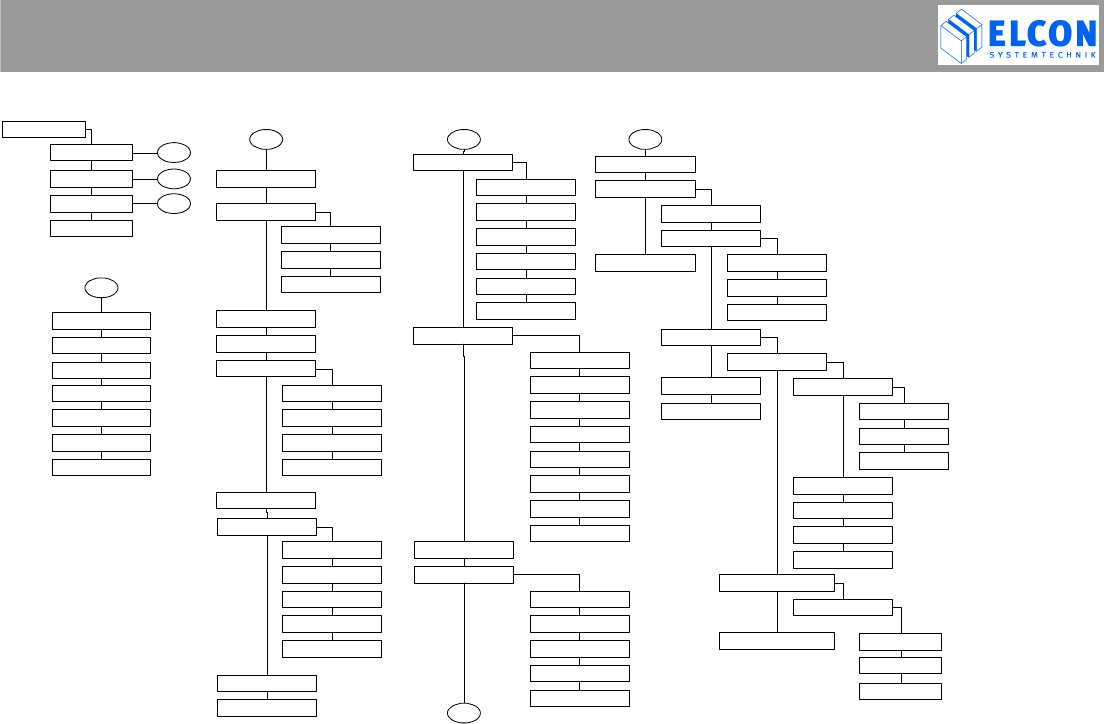
MENU STRUCTURE
E-TRIP ® Version: 2004/08/16 Order No.: 9502 Page 51
Menu..
Functions..
Emergency Call
Driving Times..
Driver Activity
Trip End
Show Trip Start
Messages..
Warnings..
Alarm Timer
Outgoing a/b
Text selection
Max. Speed
Max.Engine Speed
Max. Temperature
Min. Temperature
ORBCOMM Setup
Message Setup..
Recipient No.
Emergency No.
Service Center
GSM Setup..
Tones..
Display..
Keyb.Brightness
Date/Time..
Language
System..
Volume
Key click
Acknowledge tone
Error tone
Contrast
Brightness
Distance Unit
Speed Unit
Temperature Unit
Format Time/Date
Adjustment
Time zone
Services..
Summer time
GMT time
Company LOG..
Log-off
Log-in data
Info..
- - - - - - - - - -
- - - - - - - - - -
- - - - - - - - - -
- - - - - - - - - -
- - - - - - - - - -
- - - - - - - - - -
- - - - - - - - - -
- - - - - - - - - -
- - - - - - - - - -
2
2
Aux.RelayOutput
- - - - - - - - - -
- - - - - - - - - -
PSRR connection
1b
1b
- - - - - - - - - -
Malfunctions
E-TRIP Info
1c
1c
Position Msgs..
Switch on/off
- - - - - - - - - -
Interval Timer
- - - - - - - - - -
Card Info
PSRR Info
Position Msgs..
Switch on/off
- - - - - - - - - -
Interval Timer
GSM Info
ORBCOMM Info - - - - - - - - - -
Incoming a/b
Driver Card,
System Card,
Workshop Card
*2)
*1)
*)
*)
,
*)
,
*)
,
Warning tone
1a 1a
Driver ID
Refuel
Gallon Unit
5. APPENDICES
E-TRIP ® Version: 2004/08/16 Order No.: 9502 Page 52
5.2 Symbols and Symbol Combinations
Symbol(s) Equipment
smart card
time
Smart Card Types
driver card inserted, no errors
system card inserted
workshop card inserted
Events
Card inserted, reading card type
?no card inserted
card error or invalid card
v 50 mph programmed speed exceeded, intermittent on line 2
n 3000RPM programmed engine speed exceeded, intermittent on line 2
PIN Input the personal identification number, up to 8 numerical characters (see: page 13)
Driver ID Input your driver ID, up to 8 alphanumerical characters;
tone sequence (see: page 13, Driver ID)
Message Message received; tone sequence (see: page 31, Incoming Message)
Temp. -18.0°C temperature exceeded the programmed value, intermittent on line 2
Temp. -20.0°C temperature falls below the programmed value, intermittent on line 2

5. APPENDICES
E-TRIP ® Version: 2004/08/16 Order No.: 9502 Page 53
5.3 Error Codes
Code Error Description
1 PPP connection via service interface or PSRR is active, switch to NMEA output currently not possible
2 Error when reading company data from system card
3 Company ID on system card does not comply with log-in data
4 PSRR interface unable to be opened
5 PSRR parameters unable to be read
6 PSRR subscription unable to be performed
7 Vehicle data set not found
PSRR parameters on system card do not comply with those in E-TRIP®
8 No proper power-off performed, possibly power supply was removed from E-TRIP®
9 Company ID of the driver card does not comply with ID stored when logging in.
10 Error when reading driver ID
11 No E-TRIP® smart card inserted
12 Invalid smart card ID
13 Error when storing system data;
Please refer to the product service should this error occur once more!
14 Configuration error. One or more characters within the PIN (for ARO) are not numeric.
15 Message could not be sent via GSM.
16 Message could not be sent via satellite (ORBCOMM).
17 Cannot read company key from smart card
18 Workshop service required. Lithium battery to low.
19 Workshop service required. ARO undefined

5. APPENDICES
E-TRIP ® Version: 2004/08/16 Order No.: 9502 Page 54
GSM error codes:
100 GSM: Unknown error.
101 GSM: Hardware problem.
102 GSM: No SIM card inserted.
103 GSM: SIM card defect.
104 GSM: SIM wrong PIN.
105 GSM: Initializing
106 GSM: The changed configuration will only become active after the onboard computer is switched off for at
least a minute.
107 GSM: Registration denied by service provider.
109 GSM: not registered
112 GSM: Network out of order (check SIM card validity period)
113 GSM: Network temporary failure
114 GSM: Network congestion
115 GSM: Invalid fleet manager or emergency number.
116 GSM: Invalid service center number.
117 GSM: Sending of SMS rejected by service provider.
118 GSM: PUK required.
119 GSM: Bad quality (check antenna).

5. APPENDICES
E-TRIP ® Version: 2004/08/16 Order No.: 9502 Page 55
SAT error codes:
200 SAT: Unknown error.
201 SAT: Hardware problem.
202 SAT: Unavailable
204 SAT: Bad quality (check antenna).
205 SAT: Initializing
GPS error codes:
300 GPS: Unknown error.
301 GPS: Hardware problem.
302 GPS: Unavailable
304 GPS: Bad quality (check antenna).
5. APPENDICES
E-TRIP ® Version: 2004/08/16 Order No.: 9502 Page 56
5.4 LED Codes
Static Signal
LED
Off Green Yellow Red
1 Smart card able to be
inserted valid smart card
inserted reading from smart card HW system start
writing to smart card
2 trip is active;
trip start has taken
place
trip start ready to take
place HW system start
3 all components OK system being initialized;
BSW was started HW system start
PPP connection active
low priority priority high priority
Intermittent Signal
LED
Green 0.5 Hz Green 2 Hz Yellow 0.5 Hz Yellow 2 Hz
Red 0.5 Hz
Red 2 Hz
1 card ready to be
removed
*1.1) power down
being initiated
company
log-in missing;
insert system
card
card write error
approx. ca. 5 s
2 warning being
displayed *2.6)
3
at least 1 not
displayed
message
available
system being
updated *3.3) initialization error
HW error 2
HW error 1
low priority priority high priority

5. APPENDICES
E-TRIP ® Version: 2004/08/16 Order No.: 9502 Page 57
*1.1) At the same time, the LCD reads that the card is to be removed. This text will be deleted when a key is pressed next
time. The LED, however, keeps this status as long as the card is not removed.
*2.6) The LCD shows a warning or an error message to be acknowledged pressing C or M/OK.
*3.3) BSW updates system components (SW update, flash disk formatting, etc.)
5.5 Abbreviations
ARO Auxiliary Relay Output
Remote signal through GSM to lock the Auxiliary Relay Output. Customized function.
DST Daylight Saving Time
ETC Electronic Toll Collection
FAKRA Commission for motor vehicle standards within DIN
FAS Fleet Analysis System
GMT Greenwich Mean Time; in fact identical to UTC
GPS Global Positioning System
GSM Global System for Mobile Communications ( Cell Phone )
NMEA National Marine Electronics Association
PIN Personal Identification Number.
PSRR Private Short Range Radio
RSSI Radio Signal Strength Indication
UTC Universal Time Coordinated (coordinated world time).

6. TECHNICAL DATA
E-TRIP ® Version: 2004/08/16 Order No.: 9502 Page 58
6 TECHNICAL DATA
This chapter is subject to modifications!
Smart card:
Note:
Stickers, which are to be glued on the Smart card, must
cover the whole back of the Smart card.
6.1 Dimensions
Housing (w x h x d) 179 x 50 x 176 mm
Front panel (w x h x d) 188 x 58 x 15,2 mm
Built-in position user-defined
Smart cards:
Maximum bending longitudinal axis 2 cm
traverse axis 2 cm
Maximum torsion longitudinal axis 15°
6.2 Environmental Data
Ambient temperature:
-40 °C to +85 °C (-40 F to +185 F)
Smart card:
-30 °C to +50 °C (-22 F to +122 F)
Smart card connector:
-25 °C to +65 °C (-13 F to +149 F)
GSM module:
-20 °C to +70 °C (-4 F to +158 F)
PSRR module:
-20 °C to +70 °C (-4 F to +158 F)
LCD:
-20 °C to +70 °C (-4 F to +158 F)
Maximum relative humidity 90%
Condensation might still occur.
E-TRIP® is resistant against vibration und shock resulting
from bad road conditions and vehicle resonance. It is
protected against condensed water and dust as occurring
during the daily use.
NOTE Do not treat smart cards with solvents! Avoid
direct solar radiation!
IMPORTANT NOTE
Make sure that the Smart card never
remains in a hot vehicle !

6. TECHNICAL DATA
E-TRIP ® Version: 2004/08/16 Order No.: 9502 Page 59
6.3 Electrical Data
Power supply, nominal value +12 V
Full functionality within operation
voltage range 9 V to 36 V
Maximum power consumption
during operation 20 W
Maximum performance power
consumption in standby mode
(mean value, without peripherals) 1 mA at 24 V
The power supply input is reverse-polled protected.
Upon disconnecting the power supply, the controller is
supplied for at least further 20 ms to make sure that critical
data can be written into the flash memory.
Board voltage rises above the operation value and drops
below this value will result neither in data loss nor
undefined states in the CPU board software or controller
modules.
6.4 Standards
E-TRIP® meets the requirements laid down in the following
standards:
• FCC Part 15 (47 CFR Part 15)
• RSS 139
• FCC Part 24 (47 CFR Part 24)
• UL 94
• SAE J1113 • UL 1642
• ISO 7637 • EN 60950 / 41003
• ISO 11452 • EN 300 487
• ISO 10605 • CTR 6
• IEC 60068 • EN 301 489 /-1/-6/-7/-19
• ICES 003 • RL95/54/EG
• CS 03 • SAE J1455
• RSS 102

7. INDEX
E-TRIP ® Version: 2004/08/16 Order No.: 9502 Page 60
7 INDEX
Abbreviations 56
Alarm Time 34
Auxiliary Relay Output (ARO) 7
Average Speed 16
Bringing into service 10
Company LOG 41
Date/Time
Adjustment 39
Format 38
GMT Time 40
Summer Time 40
Time Zone 39
Display
Brightness 37
Contrast 36
Digital Input 18
Symbols and Symbol Combinations 51
Driver Activity 27
Driver ID 12, 26
Drivers Log 24
Driving Times 26
Emergency Call 23
Environmental Data 57
Errors 47, 52
E-TRIP 6
Info 44
Master 6, 10
Setup 21
Using 14
Fuel see: Refuel
Consumption 18
GPS
Displaying Data 19
GSM see: Message
Info 45
Installation 8
Key click 35
Language 40
LED 10, 55
Maintenance 8
Menu
Functions 23
Main 23
Services 34
Shortcut 22
Structure 49
System 41
Message
Delete 29, 32
Incoming 30
Outgoing 28
Text selection 29
Mileage Counter 16
Operating Keys 9

7. INDEX
E-TRIP ® Version: 2004/08/16 Order No.: 9502 Page 61
ORBCOMM see: Message
Info 46
PIN 12
PSRR 7
Info 46
Special Note 4
Real-Time-Clock 7
Refuel 27
SAE-J1708 7
Vehicle Operation Data 20
Safety on the Road 3
Shortcut see: Menu
Smart card
Info 45
reader 7, 9
Status 15
Softkey 9, 22
Speed 16
Technical Data 57
Temperature 18
Tone 35
Acknowledge 35
Error 36
Sequence 30, 51
Trip
Length of trip 17
Odometer 17
Trip End 13
Trip Start 13
Unit
Distance 37
Speed 37
Temperature 38
Volume see: Tone
Warnings 32, 47
Max. Engine Speed 33
Max. Speed 33
Max. Temperature 33
Min. Temperature 34

8. LIST OF FIGURES
E-TRIP ® Version: 2004/08/16 Order No.: 9502 Page 62
8 LIST OF FIGURES
figure 1 E-TRIP® and its operating and signal elements .................................................................................10
figure 2 welcome screen.................................................................................................................................12
figure 3 screen after first download of application and after download of new application...............................13
figure 4 input PIN............................................................................................................................................13
figure 5 input driver ID ....................................................................................................................................13
figure 6 input trip end......................................................................................................................................14
figure 7 input trip start.....................................................................................................................................14
figure 8 initial display: successful and with error .............................................................................................15
figure 9 Smart card status...............................................................................................................................16
figure 10 mileage counter.................................................................................................................................17
figure 11 speed.................................................................................................................................................17
figure 12 average speed...................................................................................................................................17
figure 13 average speed, confirm reset ............................................................................................................17
figure 14 trip odometer .....................................................................................................................................18
figure 15 trip odometer, confirm reset...............................................................................................................18
figure 16 length of trip.......................................................................................................................................18
figure 17 length of trip, confirm reset ................................................................................................................18
figure 18 fuel consumption ...............................................................................................................................19
figure 19 temperature .......................................................................................................................................19
figure 20 minimum and maximum temperature values .....................................................................................19
figure 21 status display (digital input)................................................................................................................19
figure 22 GPS data, superior display ................................................................................................................20
figure 23 GPS data, subordinate display ..........................................................................................................20
figure 24 vehicle operation data, superior display, engine speed......................................................................21

8. LIST OF FIGURES
E-TRIP ® Version: 2004/08/16 Order No.: 9502 Page 63
figure 25 vehicle operation data, oil pressure/boost pressure ...........................................................................21
figure 26 vehicle operation data, oil temperature/fuel temperature ...................................................................21
figure 27 vehicle operation data, intake manifold temperature/accelerator pedal..............................................21
figure 28 vehicle operation data, cruise control status/retarder status...............................................................21
figure 29 vehicle operation data, instantaneous fuel economy/average fuel economy......................................22
figure 30 vehicle operation data, parking brake/speed limiting status ...............................................................22
figure 31 vehicle operation data, PTO status/battery potential..........................................................................22
figure 32 shortcut menu 1, menu level 1...........................................................................................................23
figure 33 shortcut menu 2, menu level 1...........................................................................................................23
figure 34 main menu.........................................................................................................................................24
figure 35 emergency call...................................................................................................................................24
figure 36 displaying drivers log .........................................................................................................................25
figure 37 duty status of drivers log....................................................................................................................26
figure 38 duty status unknown ..........................................................................................................................26
figure 39 driving times: show trip start and trip end...........................................................................................27
figure 40 input of driver ID ................................................................................................................................27
figure 41 driver activity......................................................................................................................................28
figure 42 refuel .................................................................................................................................................28
figure 43 Incoming message, menu..................................................................................................................29
figure 44 Outgoing message, base screen .......................................................................................................29
figure 45 Outgoing message, message text......................................................................................................30
figure 46 Outgoing message, message delete..................................................................................................30
figure 47 Text selection, example .....................................................................................................................31
figure 48 Incoming message.............................................................................................................................31
figure 49 Incoming message, menu..................................................................................................................31

8. LIST OF FIGURES
E-TRIP ® Version: 2004/08/16 Order No.: 9502 Page 64
figure 50 Incoming message, base screen .......................................................................................................32
figure 51 Incoming message, message text......................................................................................................32
figure 52 Incoming message, message delete..................................................................................................32
figure 53 functions, alarms ...............................................................................................................................33
figure 54 functions, warnings, max. temperature ..............................................................................................34
figure 55 functions, warnings, min. temperature ...............................................................................................35
figure 56 functions, alarm time..........................................................................................................................35
figure 57 services, tones, volume .....................................................................................................................36
figure 58 services, tones, key click ...................................................................................................................36
figure 59 services, tones, acknowledge tone ....................................................................................................36
figure 60 services, tones, error tone .................................................................................................................37
figure 61 services, display, contrast..................................................................................................................37
figure 62 services, display, brightness..............................................................................................................38
figure 63 services, display, distance unit ..........................................................................................................38
figure 64 services, display, unit speed..............................................................................................................38
figure 65 services, display, temperature unit.....................................................................................................39
figure 67 services, make settings, GMT time and date .....................................................................................40
figure 68 services, date/time, time zone ...........................................................................................................40
figure 69 services, make settings, date/time, summer time...............................................................................41
figure 70 services, make settings, summer time active/not active....................................................................41
figure 71 services, make settings, date/time, GMT time ...................................................................................41
figure 72 services, system, PSRR connection ..................................................................................................42
figure 73 services, system, display of successful fleet log-in ............................................................................42
figure 74 services, system, fleet log-off.............................................................................................................43
figure 75 services, system, fleet log-in..............................................................................................................43

8. LIST OF FIGURES
E-TRIP ® Version: 2004/08/16 Order No.: 9502 Page 65
figure 76 services, system, fleet log-off.............................................................................................................43
figure 77 message setup: recipient no., service center .....................................................................................44
figure 78 Infos, Malfunctions.............................................................................................................................45
figure 79 Malfunctions sub screen ....................................................................................................................45
figure 80 Malfunctions sub screen ....................................................................................................................45
figure 81 Infos, PSRR info ................................................................................................................................47
figure 82 error messages, examples.................................................................................................................49

AGENCY INFORMATION
E-TRIP ® Version: 2004/08/16 Order No.: 9502 Page 66
9 AGENCY INFORMATION
AVC SYSTEMS INC.
ONBOARD TECHNOLOGIES
Canada, 115 Midpark Road, Unit #1, London, ON N6N 1B2
Phone: 001 519 681-2700
Fax: 001 519 681-3782
Mail: a.v.c@bellnet.c
Kelland International Ltd.
China, Beijing 100020
Room 1512B, No. 22
Chao wai Street, Chaoyang District
Phone: 0086 10 65 88 50 58 62
Fax: 0086 10 65 88 50 63
Mail: elcon@kellandinternational.com

DEALERS
E-TRIP ® Version: 2004/08/16 Order No.: 9502 Page 67
10 DEALERS
BaTaLog GmbH
Germany, D-21394 Westergellersen
Drosselweg 4
Phone: +49(0) 41 35 / 80 07 97
Fax: +49(0) 41 35 / 80 07 37
Mail: info@BaTaLog.de
GESTECH 2001
Canada, 478, St.-Hubert, Laval (Québec) H7G 2Y9
Phone: 001 450 629 23 76
Fax: 001 450 629 26 13
Mail: RenaldLabrie@AOL.com

E-TRIP ® Version: 2004/08/16 Order No.: 9502
D – 09232 Hartmanndorf
Obere Hauptstrasse 10
Germany
www.elcon-system.de