Contents
- 1. User Manual Part 1
- 2. User Manual Part 2
User Manual Part 2

92
92 EN MANUAL ELDES ESIM364 V1.5
EKB3/
EKB3W
Enter parameter 11, time & frequency:
11 00 00 #
Example: 110000#
Cong
Tool This operation may be carried out from the PC using the ELDES Conguration Tool software.
ATTENTION: Unlike Info SMS upon request, periodic Info SMS text message does not included zone states, PGM output names and status.

93
93EN
MANUAL ELDES ESIM364 V1.5
27. SYSTEM NOTIFICATIONS
In case of a certain event, the system attempts to send an SMS text message to the rst preset user phone number only. If the user phone
number is unavailable and the system fails to receive the SMS delivery report during 20 seconds, it will attempt to send the SMS text mes-
sage to the next preset user phone number, assigned to the same partition as the previous one. The user phone number may be unavailable
due to the following reasons:
• mobile phone was switched o.
• was out of GSM signal coverage.
The system will continue sending the SMS text message to the next preset user phone numbers in the priority order until one is available.
The system sends the SMS text message only once and will not return to the rst user phone number if the last one was unavailable.
When using Dual-SIM feature, the Secondary SIM card is involved in the communication process. For more details, please refer to 31. DUAL
SIM MANAGEMENT.
The following table provides the description of system notications by SMS text message sent to the user phone number.
Seq. No. Event Description
1 System armed SMS text message sent to the user regarding armed system.
2 System disarmed SMS text message sent to the user about disarmed system.
3 General alarm SMS text message sent to the user in case of system alarm occurrence.
4 Mains power loss/
restore
SMS text message sent to the user in case the mains power supply is lost or restored
5 Battery failed SMS text message sent to the user in case the backup battery resistance is 2 or higher
(battery requires replacement).
6 Battery dead
or missing
SMS text message sent to the user in case the backup battery is not present or the battery voltage
runs below 5V.
7 Low battery SMS text message sent to the user in case the backup battery voltage is 10.5V or lower.
8 Siren fail/restore SMS text message sent to the user in case the siren is disconnected/broken or connected/xed.
9 Date/time not set SMS text message sent to the user in case system date & time is not set.
10 GSM connection failed SMS text message sent to the user in case the GSM connection is lost.
11 GSM/GPRS antenna
fail/restore
SMS text message sent to the user in case the GSM/GPRS antenna is disconnected/broken or
connected/broken.
12 Tamper alarm SMS text message sent to the user in case of tamper violation. Indicated as Tamper x.
13 Keypad failed SMS text message sent to the user in case the keypad is disconnected/broken.
14 Temperature info SMS text message sent to the user in case of temperature deviation by the set values.
15 System started SMS text message sent to the user on system startup.
16 Periodical info Info SMS text message sent to the user periodically by the set values.
17 Wireless signal loss SMS text message sent to the user in case the wireless signal is lost. Indicated as Tamper x *.
ATTENTION: The following methods provide the conguration of the master parameters, which override the notication parameters
described in 12.9. Disabling and Enabling Arm/Disarm Notications.

94
94 EN MANUAL ELDES ESIM364 V1.5
To enable/disable a certain system notication, please refer to the following conguration methods.
Disable system
notication EKB2
Menu path:
System armed: OK → CONFIGURATION → OK → aaaa → OK → SMS MESSAGES 1 → OK → SYS
ARMED EVENT → OK → DISABLE → OKK
System disarmed: OK → CONFIGURATION → OK → aaaa → OK → SMS MESSAGES 1 → OK →
SYS DISARMED EVENT → OK → DISABLE → OK
General alarm: OK → CONFIGURATION → OK → aaaa → OK → SMS MESSAGES 1 → OK →
GENERAL ALARM EV → OK → DISABLE → OK
Mains power loss/restore: OK → CONFIGURATION → OK → aaaa → OK → SMS MESSAGES 1 →
OK → MAIN POWER L/R EV → OK → DISABLE → OK
Battery failed: OK → CONFIGURATION → OK → aaaa → OK → SMS MESSAGES 1 → OK →
BATTERY FAILED → OK → DISABLE → OK
Battery dead or missing: OK → CONFIGURATION → OK → aaaa → OK → SMS MESSAGES 1 →
OK → LOW BATTERY EVENT → OK → DISABLE → OK
Low battery: OK → CONFIGURATION → OK → aaaa → OK → SMS MESSAGES 1 → OK → LOW
BATTERY EVENT → OK → DISABLE → OK
Siren fail/restore: OK → CONFIGURATION → OK → aaaa → OK → SMS MESSAGES 1 → OK →
SIREN FAIL/REST EV → OK → DISABLE → OK
Date/time not set: OK → CONFIGURATION → OK → aaaa → OK → SMS MESSAGES 2 → OK →
DATE/TIME NOT SET → OK → DISABLE → OK
GSM connection failed: OK → CONFIGURATION → OK → aaaa → OK → SMS MESSAGES 2 → OK
→ GSM CONNECT FAILED → OK → DISABLE → OK
GSM/GPRS antenna fail/restore: OK → CONFIGURATION → OK → aaaa → OK → SMS
MESSAGES 2 → OK → GSM ANT FAIL/REST → OK → DISABLE → OK
Tamper alarm: OK → CONFIGURATION → OK → aaaa → OK → SMS MESSAGES 2 → OK →
TAMPER ALARM → OK → DISABLE → OK
Keypad failed: OK → CONFIGURATION → OK → aaaa → OK → SMS MESSAGES 2 → OK →
KEYPAD FAILED → OK → DISABLE → OK
Temperature info: OK → CONFIGURATION → OK → aaaa → OK → SMS MESSAGES 2 → OK →
TEMP INFO EVENT → OK → DISABLE → OK
System started: OK → CONFIGURATION → OK → aaaa → OK → SMS MESSAGES 2 → OK →
SYSTEM STARTED EV → OK → DISABLE → OK
Periodical info: OK → CONFIGURATION → OK → aaaa → OK → SMS MESSAGES 2 → OK →
PERIOD INFO SMS EV → OK → DISABLE → OK
Wireless signal loss: OK → CONFIGURATION → OK → aaaa → OK → SMS MESSAGES 2 → OK →
WLESS SIGN LOSS EV → OK → DISABLE → OK
Value: aaaa – 4-digit administrator password.
EKB3/
EKB3W
Enter parameter 25, event number & parameter status value:
25 01 0 # - System armed event
25 02 0 # - System disarmed event
25 03 0 # - General alarm
25 04 0 # - Main power loss/restore
25 05 0 # - Battery failed
25 06 0 # - Battery dead or missing
25 07 0 # - Low battery
25 08 0 # - Siren fail/restore
25 10 0 # - Date/time not set
25 11 0 # - GSM connection failed
25 12 0 # - GSM/GPRS antenna fail/restore
25 13 0 # - Tamper alarm
25 14 0 # - Keypad failed
25 15 0 # - Temperature info
25 16 0 # - System started
25 17 0 # - Periodical info
25 18 0 # - Wireless signal loss
Example: 25040#
Cong
Tool This operation may be carried out from the PC using the ELDES Conguration Tool software.

95
95EN
MANUAL ELDES ESIM364 V1.5
Enable system
notication EKB2
Menu path:
System armed: OK → CONFIGURATION → OK → aaaa → OK → SMS MESSAGES 1 → OK → SYS
ARMED EVENT → OK → ENABLE → OK
System disarmed: OK → CONFIGURATION → OK → aaaa → OK → SMS MESSAGES 1 → OK →
SYS DISARMED EVENT → OK → ENABLE → OK
General alarm: OK → CONFIGURATION → OK → aaaa → OK → SMS MESSAGES 1 → OK →
GENERAL ALARM EV → OK → ENABLE → OK
Mains power loss/restore: OK → CONFIGURATION → OK → aaaa → OK → SMS MESSAGES 1 →
OK → MAIN POWER L/R EV → OK → ENABLE → OK
Battery failed: OK → CONFIGURATION → OK → aaaa → OK → SMS MESSAGES 1 → OK →
BATTERY FAILED → OK → ENABLE → OK
Battery dead or missing: OK → CONFIGURATION → OK → aaaa → OK → SMS MESSAGES 1 →
OK → BATTERY DEAD/MISS → OK → ENABLE → OK
Low battery: OK → CONFIGURATION → OK → aaaa → OK → SMS MESSAGES 1 → OK → LOW
BATTERY EVENT → OK → ENABLE → OK
Siren fail/restore: OK → CONFIGURATION → OK → aaaa → OK → SMS MESSAGES 1 → OK →
SIREN FAIL/REST EV → OK → ENABLE → OK
Date/time not set: OK → CONFIGURATION → OK → aaaa → OK → SMS MESSAGES 2 → OK →
DATE/TIME NOT SET → OK → ENABLE → OK
GSM connection failed: OK → CONFIGURATION → OK → aaaa → OK → SMS MESSAGES 2 → OK
→ GSM CONNECT FAILED → OK → ENABLE → OK
GSM/GPRS antenna fail/restore: OK → CONFIGURATION → OK → aaaa → OK → SMS
MESSAGES 2 → OK → GSM ANT FAIL/REST → OK → ENABLE → OK
Tamper alarm: OK → CONFIGURATION → OK → aaaa → OK → SMS MESSAGES 2 → OK →
TAMPER ALARM → OK → ENABLE → OK
Keypad failed: OK → CONFIGURATION → OK → aaaa → OK → SMS MESSAGES 2 → OK →
KEYPAD FAILED → OK → ENABLE → OK
Temperature info: OK → CONFIGURATION → OK → aaaa → OK → SMS MESSAGES 2 → OK →
TEMP INFO EVENT → OK → ENABLE → OK
System started: OK → CONFIGURATION → OK → aaaa → OK → SMS MESSAGES 2 → OK →
SYSTEM STARTED EV → OK → ENABLE → OK
Periodical info: OK → CONFIGURATION → OK → aaaa → OK → SMS MESSAGES 2 → OK →
PERIOD INFO SMS EV → OK → ENABLE → OK
Wireless signal loss: OK → CONFIGURATION → OK → aaaa → OK → SMS MESSAGES 2 → OK →
WLESS SIGN LOSS EV → OK → ENABLE → OK
Value: aaaa – 4-digit administrator password.
EKB3/
EKB3W
Enter parameter 25, event number & parameter status value:
25 01 1 # - System armed event
25 02 1 # - System disarmed event
25 03 1 # - General alarm
25 04 1 # - Main power loss/restore
25 05 1 # - Battery failed
25 06 1 # - Battery dead or missing
25 07 1 # - Low battery
25 08 1 # - Siren fail/restore
25 10 1 # - Date/time not set
25 11 1 # - GSM connection failed
25 12 1 # - GSM/GPRS antenna fail/restore
25 13 1 # - Tamper alarm
25 14 1 # - Keypad failed
25 15 1 # - Temperature info
25 16 1 # - System started
25 17 1 # - Periodical info
25 18 1 # - Wireless signal loss
Example: 25061#
Cong
Tool This operation may be carried out from the PC using the ELDES Conguration Tool software.

96
96 EN MANUAL ELDES ESIM364 V1.5
27.1. SMSC (Short Message Service Center) Phone Number
An SMS center (SMSC) is a GSM network element, which routes SMS text messages to the destination user and stores the SMS text message
if the recipient is unavailable. Typically, the phone number of the SMS center is already stored in the SIM card provided by the GSM operator.
If the user fails to receive replies from the system, the SMS center phone number, provided by the GSM operator, must be set manually.
Set SMSC phone
number SMS
SMS text message content:
ssss_SMS_+ttteeellnnuumm
Value: ssss – 4-digit SMS password; ttteeellnnuumm – up to 15 digits SMSC phone number.
Example: 1111_SMS_+4417031111111
ATTENTION: Before setting the SMSC phone number, please check the credit balance of the system’s SIM card. The system will fail to reply
if the credit balance is insucient.

97
97EN
MANUAL ELDES ESIM364 V1.5
28. EVENT LOG
This feature allows to chronologically register up to 500 timestamped records regarding the following system events:
• System start.
• System arming/disarming.
• Zone violated/restored.
• Tamper violated/restored.
• Zone bypassing.
• Wireless device management.
• Temperature deviation by MIN and MAX boundaries.
• System faults.
The event log is of LIFO (last in, rst out) type that allows the system to automatically replace the oldest records with the the latest ones.
View event log EKB2
Menu path:
OK → VIEW EVENT LOG → OK → uuuu → OK
Value: uuuu - 4-digit user password.
To export the event log to .log le or clear it, please refer to the following conguration method.
Export/clear event log Cong
Tool This operation may be carried out from the PC using the ELDES Conguration Tool software.
By default, event log is enabled. To disable/enable this feature, please refer to the following conguration methods.
Disable event log EKB2 Menu path:
OK → CONFIGURATION → OK → aaaa → OK → PRIMARY SETTINGS → OK → EVENT LOG → OK
→ DISABLE → OK
EKB3/
EKB3W
Enter parameter 36 and parameter status value:
36 0 #
Example: 360#
Cong
Tool This operation may be carried out from the PC using the ELDES Conguration Tool software.
Enable event log EKB2 Menu path:
OK → CONFIGURATION → OK → aaaa → OK → PRIMARY SETTINGS → OK → EVENT LOG → OK
→ ENABLE → OK
EKB3/
EKB3W
Enter parameter 36 and parameter status value:
36 1 #
Example: 361#
Cong
Tool This operation may be carried out from the PC using the ELDES Conguration Tool software.

98
98 EN MANUAL ELDES ESIM364 V1.5
29. INDICATION OF SYSTEM FAULTS
EN50131-1
GRADE 3
To comply with EN50131-1 Grade 3 standard requirements, the system must be equipped with the following feature:
• System arming is blocked if any system fault exists. The user wil not be able to arm the system until all existing system
faults are solved.
For complete list of EN50131-1 Grade 3 standard requirements and how to enable/disable the associated features, please
refer to 35. EN 50131-1 GRADE 3.
The system comes equipped with self-diagnostic feature allowing to indicate the presence of any system fault by the keypad as well as by
SMS text message notication to the preset user phone number. By default the indication for all system faults is indicated on the keypad.
To disable/enable the indication of a certain system fault, please refer to the following conguration method.
Disable/enable
individual system fault
indication on keypad
Cong
Tool This operation may be carried out from the PC using the ELDES Conguration Tool software.
NOTE: After enabling/disabling a certain system fault indication, it is necessary to restart the system by fully powering it down and power-
ing it up again.
EKB2
Message FLT displayed in the home screen view indicates presence of system faults. In order to nd out more on the particular
system problem, please open menu section FAULTS. The description on each system problem is indicated in the table below.
Menu path:
OK → FAULTS
Name Description
MAIN POWER LOSS Mains power supply is lost
LOW BATTERY Low backup battery power - backup battery
voltage is 10.5V or lower
BATTERY DEAD/MISS Backup battery is not present or the battery
voltage runs below 5V
BATTERY FAILED Backup battery requires replacement - backup
battery resistance is 2 or higher
SIREN FAILED Siren is disconnected/broken
VIOLATED TAMPER One or more tampers are violated
DATE/TIME NOT SET Date/time not set
GSM CONNECT FAILED GSM connection is lost
GSM/GPRS ANTENNA FAILED GSM/GPRS antenna is disconnected/broken
WLESS ANTENNA FAIL Wireless antenna is disconnected/broken

99
99EN
MANUAL ELDES ESIM364 V1.5
EKB3/
EKB3W
Yellow LED SYSTEM indicates system faults. SYSTEM LED indications are mentioned in the table below.
SYSTEM LED Description
Illuminated continously One or more tampers are violated; other system faults (see below)
Flashing One or more high-numbered zones are violated
In order to nd out more on the particular system fault, please enter command A provided below. After this procedure the system
will activate red zone LEDs for 15 seconds. The description on each LED indication is mentioned in the table below.
Zone LED Description
1 Mains power supply is lost
2 Low backup battery power - backup battery voltage is 10.5V or lower
3 Backup battery is not present or the battery voltage runs below 5V
4 Backup battery requires replacement - backup battery resistance is 2 or
higher
5 Siren is disconnected/broken
7 One or more tampers are violated
8 Date/time not set
9 GSM connection is lost
10 One or more high-numbered zones (Z13 - Z76) are violated
11 GSM/GPRS antenna is disconnected/broken
12 Wireless antenna is disconnected/broken
In order to nd out which particular high-numbered zone is violated please , enter command B.
In order to nd out which particular tamper is violated please , enter command C.
A. System fault indication - enter command:
[CODE#]
B. Violated high-numbered zone indication – enter command:
[CODE1]
C. Violated tamper indication – enter command:
[CODE2]
The number of violated high-numbered zone or tamper can be calculated using the table below according to the formula: number
from zone LED section B + number from zone LED section A.
Example: LED #3 from section A is ashing and LED #8 from section B is illuminated continuously. According to the table below
LED #8 is equal to number 18, therefore 18 + 3 = 21.
Result: Violated high-numbered zone or tamper number is 21.
Zone LED section - A (ashing) Zone LED section - B (illuminated continously)
Zone LED 1 = 1 Zone LED 7 = 12
Zone LED 2 = 2 Zone LED 8 = 18
Zone LED 3 = 3 Zone LED 9 = 24
Zone LED 4 = 4 Zone LED 10 = 30
Zone LED 5 = 5 Zone LED 11 = 36
Zone LED 6 = 6 Zone LED 12 = 42

100
100 EN MANUAL ELDES ESIM364 V1.5
30. MONITORING STATION
The system can be congured to report events to the monitoring station by transmitting data messages to the monitoring station. The
system connects to the monitoring station when the MS (Monitoring Station) mode is enabled.
Enable MS mode SMS
SMS text message content:
ssss_SCNSET:ON
Value: ssss – 4-digit SMS password.
Example: 1111_SCNSET:ON
EKB2
Menu path:
OK → CONFIGURATION → OK → aaaa → OK → MS SETTINGS → OK → MS MODE → OK →
ENABLE → OK
Value: aaaa – 4-digit administrator password
EKB3/
EKB3W
Enter parameter 23 & parameter status value:
23 1 #
Example: 231#
Cong
Tool This operation may be carried out from the PC using the ELDES Conguration Tool software.
Disable MS mode SMS
SMS text message content:
ssss_SCNSET:OFF
Value: ssss – 4-digit SMS password.
Example: 1111_SCNSET:OFF
EKB2
Menu path:
OK → CONFIGURATION → OK → aaaa → OK → MS SETTINGS → OK → MS MODE → OK →
DISABLE → OK
Value: aaaa – 4-digit administrator password
EKB3/
EKB3W
Enter parameter 23 & parameter status value:
23 0 #
Example: 230#
Cong
Tool This operation may be carried out from the PC using the ELDES Conguration Tool software.
Account is a 4-digit number (By default – 9999) required to identify the alarm system unit by the monitoring station.
Set account EKB2
Menu path:
OK → CONFIGURATION → OK → aaaa → OK → MS SETTINGS → OK → ACCOUNT → OK → cccc
→ OK
Value: aaaa – 4-digit administrator password; cccc – 4-digit account number.
EKB3/
EKB3W
Enter parameter 27 & account number:
27 cccc #
Value: cccc – 4-digit account number.
Example: 278853#
Cong
Tool This operation may be carried out from the PC using the ELDES Conguration Tool software.
ATTENTION: The system will NOT send any data to the monitoring station while remote conguration, remote rmware update or remote
listening/2-way voice communication is in progress. However, during the remote conguration session, rmware update process or remote
listening/2-way voice communication process, the data messages will be queued up and transmitted to the monitoring station after the
remote conguration session, rmware update or remote listening/2-way voice communication process is over.
ATTENTION: Phone calls to the preset user phone number in case of alarm are disabled by force when MS mode is enabled.

101
101EN
MANUAL ELDES ESIM364 V1.5
30.1. Data Messages – Events
The conguration of data messages is based on Ademco Contact ID protocol. The data messages can either be transmitted to the monitor-
ing station alone or with duplication by SMS text message to preset user phone number. For more details on system notications by SMS
text message, please refer to 27. SYSTEM NOTIFICATIONS.
Seq. No. Contact ID® Code Event Description
1 1110 Fire alarm Transmitted in case a zone of Fire type is violated.
2 3110 Fire restore Transmitted in case a zone of Fire type is restored.
3 1121 Disarmed by user (Duress
password)
Transmitted in case the system is disarmed by Duress password.
4 1130 Burglary alarm Transmitted in case a zone of Delay (if not disarmed before entry delay
countdown is completed), Interior Follower or Instant type is violated.
5 3130 Burglary restore Transmitted in case a zone of Delay (if not disarmed before entry delay
countdown is completed), Interior Follower or Instant type is restored.
6 1133 24-Hour zone alarm Transmitted in case of zone of 24-Hour type is violated.
7 3133 24-Hour zone restore Transmitted in case of zone of 24-Hour type is restored.
8 1144 Tamper alarm Transmitted in case the tamper is violated.
9 3144 Tamper restore Transmitted in case the tamper is restored.
10 1146 Panic/Silent zone alarm Transmitted in case of zone of Panic/Silent type is violated.
11 3146 Panic/Silent zone restore Transmitted in case of zone of Panic/Silent type is restored.
12 1158 Temperature risen Transmitted in case of the temperature has increased above the MAX set
value.
13 1159 Temperature fallen Transmitted in case of temperature has decreased below the MIN set value.
14 1301 Mains power loss Transmitted in case the main power supply is lost.
15 3301 Mains power restore Transmitted in case the main power supply is restored.
16 1302 Low battery Transmitted in case the backup battery voltage is 10.5V or lower / the
wireless sensor battery level runs below 5%.
17 1308 System shutdown When the system is running on backup battery power, it transmits the data
message before the backup battery power is fully depleted.
18 1309 Battery failed Transmitted in case the backup battery resistance is 2 or higher.
19 1311 Battery dead or missing Transmitted in case the backup battery is not present or the battery volt-
age runs below 5V.
20 3311 Battery connection restore Transmitted in case the backup battery connecton is xed.
21 1321 Siren fail Transmitted in case the siren is disconnected/broken.
22 3321 Siren restore Transmitted in case the siren is connected/xed.
23 1330 Keypad fail Transmitted in case the keypad is disconnected/broken.
24 3330 Keypad restore Transmitted in case the keypad is connected/xed
25 1354 GPRS connection loss Transmitted in case the GPRS connection is lost.
26 1358 GSM connection failed Transmitted in case the GSM connection is lost.
27 1359 GSM/GPRS antenna fail Transmitted in case the GSM/GPRS antenna is disconnected/broken
28 3359 GSM/GPRS antenna restore Transmitted in case the GSM/GPRS antenna is connected/xed.
29 1381 Wireless signal loss Transmitted in case the connection with any wireless device is lost.
30 3381 Wireless signal restore Transmitted in case the connection with any wireless device is restored.
31 1401 Disarmed by user Transmitted in case the system is disarmed.
32 3401 Armed by user Transmitted in case the system is armed.
33 1456 Disarmed in Stay mode Transmitted in case the system is disarmed in Stay mode.
34 3456 Armed in Stay mode Transmitted in case the system is armed in Stay mode.
35 1463 Disarmed by user (SGS
password)
Transmitted in case the system is disarmed by SGS password.
36 3463 Armed by user (SGS
password)
Transmitted in case the system is armed by SGS password.
37 1570 Zone bypassed Transmitted in case a violated zone is bypassed.
38 3570 Bypassed zone activated Transmitted in case a bypassed zone is activated.
39 1602 Test event/Kronos ping Transmitted for system online status verication purposes.
40 3626 Date/time not set Transmitted in case system date & time is not set.
41 1900 System started Transmitted on system startup.

102
102 EN MANUAL ELDES ESIM364 V1.5
The following table refers to user codes included in arm/disarm data messages.
Type Code
User Phone Number 1 0
User Phone Number 2 1
User Phone Number 3 2
User Phone Number 4 3
User Phone Number 5 4
User Phone Number 6 5
User Phone Number 7 6
User Phone Number 8 7
User Phone Number 9 8
User Phone Number 10 9
iButton 1 10
iButton 2 11
iButton 3 12
iButton 4 13
iButton 5 14
iButton 6 15
iButton 7 16
iButton 8 17
iButton 9 18
iButton 10 19
iButton 11 20
iButton 12 21
iButton 13 22
iButton 14 23
iButton 15 24
iButton 16 25
User Password 1 26
User Password 2 27
User Password 3 28
User Password 4 29
User Password 5 30
User Password 6 31
User Password 7 32
User Password 8 33
User Password 9 34
User Password 10 35
User Password 11 36
User Password 12 37
User Password 13 38
User Password 14 39
User Password 15 40
User Password 16 41
User Password 17 42
User Password 18 43
User Password 19 44
User Password 20 45
User Password 21 46
User Password 22 47
User Password 23 48
User Password 24 49
User Password 25 50
User Password 26 51
User Password 27 52
User Password 28 53
User Password 29 54
User Password 30 55
Remote Code (EGR100) 56
KeyFob 1 133

103
103EN
MANUAL ELDES ESIM364 V1.5
KeyFob 2 134
KeyFob 3 135
KeyFob 4 136
KeyFob 5 137
Arm/Disarm by Zone 213
Disable data message EKB2
Menu path:
Burglary alarm/restore: OK → CONFIGURATION → OK → aaaa → OK → MS SETTINGS → OK →
DATA MESSAGES 1 → OK → BURGLR ALM/REST EV → OK → DISABLE → OK
Mains power loss/restore: OK → CONFIGURATION → OK → aaaa → OK → MS SETTINGS → OK
→ DATA MESSAGES 1 → OK → MAIN POWER L/R EV → OK → DISABLE → OK
Armed/disarmed by user: OK → CONFIGURATION → OK → aaaa → OK → MS SETTINGS → OK
→ DATA MESSAGES 1 → OK → ARM/DISARM EVENT → OK → DISABLE → OK
Battery failed: OK → CONFIGURATION → OK → aaaa → OK → MS SETTINGS → OK → DATA
MESSAGES 1 → OK → BATTERY FAILED → OK → DISABLE → OK
Battery dead or missing/battery connection restore: OK → CONFIGURATION → OK → aaaa
→ OK → MS SETTINGS → OK → DATA MESSAGES 1 → OK → BATTERY DEAD/MISS → OK →
DISABLE → OK
Test event: OK → CONFIGURATION → OK → aaaa → OK → MS SETTINGS → OK → DATA
MESSAGES 1 → OK → TEST EVENT → OK → DISABLE → OK
Tamper alarm/restore: OK → CONFIGURATION → OK → aaaa → OK → MS SETTINGS → OK →
DATA MESSAGES 1 → OK → TAMPER ALM/REST EV → OK → DISABLE → OK
Panic/Silent zone alarm/restore: OK → CONFIGURATION → OK → aaaa → OK → MS
SETTINGS → OK → DATA MESSAGES 1 → OK → PA/SIL ALM/REST EV → OK → DISABLE → OK
System started: OK → CONFIGURATION → OK → aaaa → OK → MS SETTINGS → OK → DATA
MESSAGES 1 → OK → SYSTEM STARTED EV → OK → DISABLE → OK
Fire alarm/restore: OK → CONFIGURATION → OK → aaaa → OK → MS SETTINGS → OK →
DATA MESSAGES 1 → OK → FIRE ALM/REST EV → OK → DISABLE → OK
24-Hour zone alarm/restore: OK → CONFIGURATION → OK → aaaa → OK → MS SETTINGS →
OK → DATA MESSAGES 1 → OK → 24H ALM/REST EVENT→ OK → DISABLE → OK
Low battery: OK → CONFIGURATION → OK → aaaa → OK → MS SETTINGS → OK →DATA
MESSAGES 1 → OK → LOW BATTE RY EVENT → OK → DISABLE → OK
Temperature risen: OK → CONFIGURATION → OK → aaaa → OK → MS SETTINGS → OK →
DATA MESSAGES 1 → OK → TEMP HIGH EVENT → OK → DISABLE → OK
Temperature fallen: OK → CONFIGURATION → OK → aaaa → OK → MS SETTINGS → OK →
DATA MESSAGES 1 → OK → TEMP LOW EVENT → OK → DISABLE → OK
Wireless signal loss/restore: OK → CONFIGURATION → OK → aaaa → OK → MS SETTINGS →
OK → DATA MESSAGES 1 → OK → WLESS SIGN L/R EV → OK → DISABLE → OK
Disarmed by user (Duress password): OK → CONFIGURATION → OK → aaaa → OK → MS
SETTINGS → OK → DATA MESSAGES 2 → OK → DISARM DURESS EV → OK → DISABLE → OK
Armed/disarmed by user (SGS password): OK → CONFIGURATION → OK → aaaa → OK → MS
SETTINGS → OK → DATA MESSAGES 2 → OK → ARM/DARM SGS EVENT → OK → DISABLE →
OK
Armed/disarmed in Stay mode: OK → CONFIGURATION → OK → aaaa → OK → MS SETTINGS
→ OK → DATA MESSAGES 2 → OK → ARM/DARM STAY EV → OK → DISABLE → OK
Siren fail/restore: OK → CONFIGURATION → OK → aaaa → OK → MS SETTINGS → OK → DATA
MESSAGES 2 → OK → SIREN FAIL/REST EV → OK → DISABLE → OK
Date/time not set: OK → CONFIGURATION → OK → aaaa → OK → MS SETTINGS → OK → DATA
MESSAGES 2 → OK → DATE/TIME NOT SET → OK → DISABLE → OK
GSM connection failed: OK → CONFIGURATION → OK → aaaa → OK → MS SETTINGS → OK →
DATA MESSAGES 2 → OK → GSM CONNECT FAILED → OK → DISABLE → OK
GSM/GPRS antenna fail/restore: OK → CONFIGURATION → OK → aaaa → OK → MS SETTINGS
→ OK → DATA MESSAGES 2 → OK → GSM ANT FAIL/REST → OK → DISABLE → OK
System shutdown: OK → CONFIGURATION → OK → aaaa → OK → MS SETTINGS → OK →
DATA MESSAGES 2 → OK → SYSTEM SHUTDOWN EV → OK → DISABLE → OK
Keypad fail/restore: OK → CONFIGURATION → OK → aaaa → OK → MS SETTINGS → OK →
DATA MESSAGES 2 → OK → KEYPAD FAIL/REST → OK → DISABLE → OK
GPRS connection failed: OK → CONFIGURATION → OK → aaaa → OK → MS SETTINGS → OK →
DATA MESSAGES 2 → OK → GPRS CONNECT FAIL → OK → DISABLE → OK
Zone bypassed/activated: OK → CONFIGURATION → OK → aaaa → OK → MS SETTINGS → OK
→ DATA MESSAGES 2 → OK → ZONE BYPASS→ OK → DISABLE → OK
Value: aaaa – 4-digit administrator password.

104
104 EN MANUAL ELDES ESIM364 V1.5
EKB3/
EKB3W
Enter parameter 24, event number & parameter status value:
24 01 0 # – Burglary alarm/restore
24 02 0 # – Mains power loss/restore
24 03 0 # – Armed/disarmed by user
24 04 0 # – Test event
24 05 0 # – Battery failed
24 06 0 # –Battery dead or missing/battery connection restore
24 07 0 # – Tamper alarm/restore
24 08 0 # – Panic/Silent zone alarm/restore
24 09 0 # – Kronos ping
24 10 0 # – System started
24 13 0 # – 24-Hour zone alarm/restore
24 14 0 # – Fire zone alarm/restore
24 15 0 # – Low battery
24 16 0 # –Temperature risen
24 17 0 # – Temperature fallen
24 18 0 # – Wireless signal loss/restore
24 19 0 # – Disarmed by user (Duress password)
24 20 0 # – Armed/disarmed by user (SGS password)
24 21 0 # – Armed/disarmed in Stay mode
24 22 0 # – Siren fail/restore
24 24 0 # –Date/time not set
24 25 0 # – GSM connection failed
24 26 0 # – GSM/GPRS antenna fail/restore
24 27 0 # – System shutdown
24 28 0 # – Keypad fail/restore
24 29 0 # – GPRS connection failed
24 30 0 # – Zone bypassed/activated
Example: 24080#
Cong
Tool This operation may be carried out from the PC using the ELDES Conguration Tool software.

105
105EN
MANUAL ELDES ESIM364 V1.5
Enable data message EKB2
Menu path:
Burglary alarm/restore: OK → CONFIGURATION → OK → aaaa → OK → MS SETTINGS → OK →
DATA MESSAGES 1 → OK → BURGLR ALM/REST EV → OK → ENABLE → OK
Mains power loss/restore: OK → CONFIGURATION → OK → aaaa → OK → MS SETTINGS → OK
→ DATA MESSAGES 1 → OK → MAIN POWER L/R EV → OK → ENABLE → OK
Armed/disarmed by user: OK → CONFIGURATION → OK → aaaa → OK → MS SETTINGS → OK
→ DATA MESSAGES 1 → OK → ARM/DISARM EVENT → OK → ENABLE → OK
Battery failed: OK → CONFIGURATION → OK → aaaa → OK → MS SETTINGS → OK → DATA
MESSAGES 1 → OK → BATTERY FAILED → OK → ENABLE → OK
Battery dead or missing/battery connection restore: OK → CONFIGURATION → OK → aaaa
→ OK → MS SETTINGS → OK → DATA MESSAGES 1 → OK → BATTERY DEAD/MISS → OK →
ENABLE → OK
Test event: OK → CONFIGURATION → OK → aaaa → OK → MS SETTINGS → OK → DATA
MESSAGES 1 → OK → TEST EVENT → OK → ENABLE → OK
Tamper alarm/restore: OK → CONFIGURATION → OK → aaaa → OK → MS SETTINGS → OK →
DATA MESSAGES 1 → OK → TAMPER ALM/REST EV → OK → ENABLE → OK
Panic/Silent zone alarm/restore OK → CONFIGURATION → OK → aaaa → OK → MS SETTINGS
→ OK → DATA MESSAGES 1 → OK → PA/SIL ALM/REST EV → OK → ENABLE → OK
System started: OK → CONFIGURATION → OK → aaaa → OK → MS SETTINGS → OK → DATA
MESSAGES 1 → OK → SYSTEM STARTED EV → OK → ENABLE → OK
Fire alarm/restore: OK → CONFIGURATION → OK → aaaa → OK → MS SETTINGS → OK →
DATA MESSAGES 1 → OK → FIRE ALM/REST EV → OK → ENABLE → OK
24-Hour zone alarm/restore: OK → CONFIGURATION → OK → aaaa → OK → MS SETTINGS →
OK → DATA MESSAGES 1 → OK → 24H ALM/REST EVENT→ OK → ENABLE → OK
Low battery: OK → CONFIGURATION → OK → aaaa → OK → MS SETTINGS → OK → DATA
MESSAGES 1 → OK → LOW BATTE RY EVENT → OK → ENABLE → OK
Temperature risen: OK → CONFIGURATION → OK → aaaa → OK → MS SETTINGS → OK →
DATA MESSAGES 1 → OK → TEMP HIGH EVENT → OK → ENABLE → OK
Temperature fallen: OK → CONFIGURATION → OK → aaaa → OK → MS SETTINGS → OK →
DATA MESSAGES 1 → OK → TEMP LOW EVENT → OK → ENABLE → OK
Wireless signal loss/restore: OK → CONFIGURATION → OK → aaaa → OK → MS SETTINGS →
OK → DATA MESSAGES 1 → OK → WLESS SIGN L/R EV → OK → ENABLE → OK
Disarmed by user (Duress password): OK → CONFIGURATION → OK → aaaa → OK → MS
SETTINGS → OK → DATA MESSAGES 2 → OK → DISARM DURESS EV → OK → ENABLE → OK
Armed/disarmed by user (SGS password): OK → CONFIGURATION → OK → aaaa → OK → MS
SETTINGS → OK → DATA MESSAGES 2 → OK → ARM/DARM SGS EVENT → OK → ENABLE → OK
Armed/disarmed in Stay mode: OK → CONFIGURATION → OK → aaaa → OK → MS SETTINGS
→ OK → DATA MESSAGES 2 → OK → ARM/DARM STAY EV → OK → ENABLE → OK
Siren fail/restore: OK → CONFIGURATION → OK → aaaa → OK → MS SETTINGS → OK → DATA
MESSAGES 2 → OK → SIREN FAIL/REST EV → OK → ENABLE → OK
Date/time not set: OK → CONFIGURATION → OK → aaaa → OK → MS SETTINGS → OK → DATA
MESSAGES 2 → OK → DATE/TIME NOT SET → OK → ENABLE → OK
GSM connection failed: OK → CONFIGURATION → OK → aaaa → OK → MS SETTINGS → OK →
DATA MESSAGES 2 → OK → GSM CONNECT FAILED → OK → ENABLE → OK
GSM/GPRS antenna fail/restore: OK → CONFIGURATION → OK → aaaa → OK → MS SETTINGS
→ OK → DATA MESSAGES 2 → OK → GSM ANT FAIL/REST → OK → ENABLE → OK
System shutdown: OK → CONFIGURATION → OK → aaaa → OK → MS SETTINGS → OK →
DATA MESSAGES 2 → OK → SYSTEM SHUTDOWN EV → OK → ENABLE → OK
Keypad fail/restore: OK → CONFIGURATION → OK → aaaa → OK → MS SETTINGS → OK →
DATA MESSAGES 2 → OK → KEYPAD FAIL/REST → OK → ENABLE → OK
GPRS connection failed: OK → CONFIGURATION → OK → aaaa → OK → MS SETTINGS → OK →
DATA MESSAGES 2 → OK → GPRS CONNECT FAIL → OK → ENABLE → OK
Zone bypassed/activated: OK → CONFIGURATION → OK → aaaa → OK → MS SETTINGS → OK
→ DATA MESSAGES 2 → OK → ZONE BYPASS→ OK → ENABLE → OK
Value: aaaa – 4-digit administrator password.

106
106 EN MANUAL ELDES ESIM364 V1.5
EKB3/
EKB3W
Enter parameter 24, event number & parameter status value:
24 01 1 # – Burglary alarm/restore
24 02 1 # – Mains power loss/restore
24 03 1 # – Armed/disarmed by user
24 04 1 # – Test event
24 05 1 # – Battery failed
24 06 1 # – Battery dead or missing/battery connection restore
24 07 1 # – Tamper alarm/restore
24 08 1 # – Panic/Silent zone alarm/restore
24 09 1 # – Kronos ping
24 10 1 # – System started
24 13 1 # – 24-Hour zone alarm/restore
24 14 1 # – Fire zone alarm/restore
24 15 1 # – Low battery
24 16 1 # – Temperature risen
24 17 1 # – Temperature fallen
24 18 1 # – Wireless signal loss/restore
24 19 1 # – Disarmed by user (Duress password)
24 20 1 # – Armed/disarmed by user (SGS password)
24 21 1 # – Armed/disarmed in Stay mode
24 22 1 # – Siren fail/restore
24 24 1 # –Date/time not set
24 25 1 # – GSM connection failed
24 26 1 # – GSM/GPRS antenna fail/restore
24 27 1 # – System shutdown
24 28 1 # – Keypad fail/restore
24 29 1 # – GPRS connection failed
24 30 1 # – Zone bypassed/activated
Example: 24031#
Cong
Tool This operation may be carried out from the PC using the ELDES Conguration Tool software.

107
107EN
MANUAL ELDES ESIM364 V1.5
30.2. Communication
The system supports the following communication methods and protocols:
• GPRS network – EGR100, Kronos protocol.
• Voice calls (GSM audio channel) – Ademco Contact ID protocol.
• RS485 data channel.
• CSD (Cricuit Switched Data).
• PSTN (landline) – Ademco Contact ID protocol.
• SMS – Cortex SMS format.
Any communication method can be set as primary or backup connection. The user can set up to 5 backup connections in any sequence order.
Initially, the system communicates via primary connection with the monitoring station. By default, if the initial attempt to transmit data is
unsuccessful, the system will make additional attempts until the data is successfully delivered. If all attempts are unsuccessful, the system
will follow this pattern:
a) The system switches to the backup connection that follows in the sequence (presumably - Backup 1).
b) The system then attempts to transmit data by the backup connection.
c) If the initial attempt is unsuccessful, the system will make additional attempts until the data is successfully delivered.
d) If the system ends up with all unsuccessful attempts, it will switch to the next backup connection in the sequence (presumably - Back-
up 2) and will continue to operate as described in the previous steps. The connection is considered unsuccessful under the following
conditions:
• GPRS network – The system has not received the ACK data message from the monitoring station within 40 seconds.
• Voice calls:
• The system has not received the “handshake” signal from the monitoring station within 40 seconds.
• The system has not received the “kisso” signal from the monitoring station within 5 attempts each lasting 1 second.
• CSD – The system has not received the ACK data message from the monitoring station within 35 seconds.
• PSTN:
• The system has not received the “handshake” signal from the monitoring station within 40 seconds.
• The system has not received the “kisso” signal from the monitoring station within 5 attempts each lasting 1 second.
• SMS – The system has not received the SMS delivery report from the SMSC (Short Message Service Center) within 45 seconds.
e) If one of the attempts is successful, the system will transmit all queued up data messages by this connection.
f) The system then returns to the primary connection and attempts to transmit the next data messages by primary connection.
g) If the system ends up with all unsuccessful attempts by all connections, it will wait until the Delay after last communication attempt
time (By default – 600 seconds) expires and will return to the primary connection afterwards.
h) If a new data message, except Test Event (ping), is generated during Delay after last communication attempt time, the system will
immediately attempt to transmit it to the monitoring station, regardless of Delay after last communication attempt being in progress.
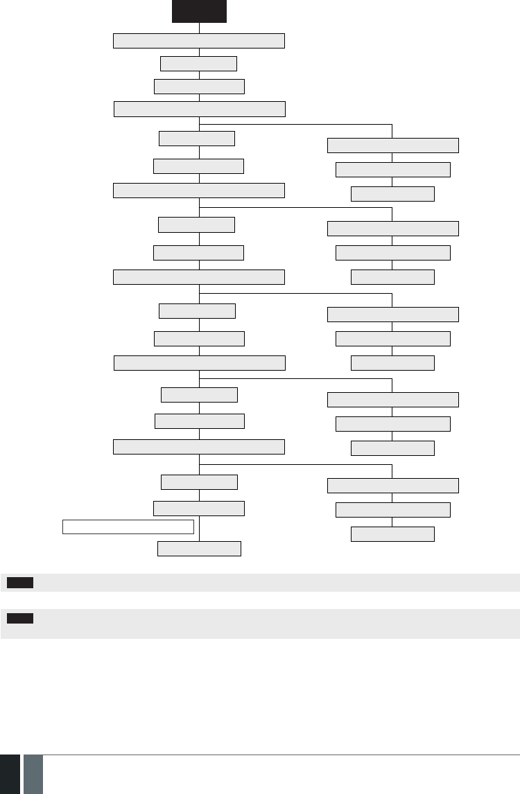
108
108 EN MANUAL ELDES ESIM364 V1.5
PRIMARY
Makes up to 3 or 5 attempts to transmit data
Makes up to 3 or 5 attempts to transmit data
Makes up to 3 or 5 attempts to transmit data
Makes up to 3 or 5 attempts to transmit data
Makes up to 3 or 5 attempts to transmit data
Makes up to 3 or 5 attempts to transmit data
All attempts failed
One of the attempts is successful
One of the attempts is successful
One of the attempts is successful
One of the attempts is successful
One of the attempts is successful
Transmits all queued up data
Transmits all queued up data
Transmits all queued up data
Transmits all queued up data
Transmits all queued up data
Returns to PRIMARY
Returns to PRIMARY
Returns to PRIMARY
Returns to PRIMARY
Returns to PRIMARY
Returns to PRIMARY
Switches to BACKUP 1
Switches to BACKUP 2
Switches to BACKUP 3
Switches to BACKUP 4
Switches to BACKUP 5
Waits for 600 seconds
All attempts failed
All attempts failed
All attempts failed
All attempts failed
All attempts failed
Delay after last communication attempt
NOTE: The number of attempts, indicated in the diagram, are default and depends on the determined communication method.
NOTE: When using Dual-SIM feature, the Secondary SIM card is involved in the communication process. For more details, please refer
to 31. DUAL SIM MANAGEMENT.

109
109EN
MANUAL ELDES ESIM364 V1.5
Set primary connection EKB2
Menu path:
GPRS network: OK → CONFIGURATION → OK → aaaa → OK → MS SETTINGS → OK →
PRIMARY CONNECTION → OK → GPRS → OK
Voice calls: OK → CONFIGURATION → OK → aaaa → OK → MS SETTINGS → OK → PRIMARY
CONNECTION → OK → VOICE CALLS → OK
RS485: OK → CONFIGURATION → OK → aaaa → OK → MS SETTINGS → OK → PRIMARY
CONNECTION → OK → RS485 → OK
CSD: OK → CONFIGURATION → OK → aaaa → OK → MS SETTINGS → OK → PRIMARY
CONNECTION → OK → CSD → OK
PSTN: OK → CONFIGURATION → OK → aaaa → OK → MS SETTINGS → OK → PRIMARY
CONNECTION → OK → PSTN → OK
SMS: OK → CONFIGURATION → OK → aaaa → OK → MS SETTINGS → OK → PRIMARY
CONNECTION → OK → SMS → OK
connection not in use: OK → CONFIGURATION → OK → aaaa → OK → MS SETTINGS → OK →
PRIMARY CONNECTION → OK → N/A → OK
Value: aaaa – 4-digit administrator password.
EKB3/
EKB3W
Enter parameter 48 & communication method number:
48 0 # – GPRS network
48 1 # – Voice calls
48 2 # – RS485
48 3 # – CSD
48 4 # – PSTN
48 5 # – SMS
48 6 # – connection not in use
Example: 484#
Cong
Tool This operation may be carried out from the PC using the ELDES Conguration Tool software.
Set backup connection
1... 5 EKB2
Menu path:
GPRS network: OK → CONFIGURATION → OK → aaaa → OK → MS SETTINGS → OK → BACKUP
CONNECTION1... 5 → OK → GPRS → OK
Voice calls: OK → CONFIGURATION → OK → aaaa → OK → MS SETTINGS → OK → BACKUP
CONNECTION1... 5 → OK → VOICE CALLS → OK
RS485: OK → CONFIGURATION → OK → aaaa → OK → MS SETTINGS → OK → BACKUP
CONNECTION1... 5 → OK → RS485 → OK
CSD: K → CONFIGURATION → OK → aaaa → OK → MS SETTINGS → OK →
BACKUP CONNECTION1... 5 → OK → CSD → OK
PSTN: OK → CONFIGURATION → OK → aaaa → OK → MS SETTINGS → OK → BACKUP
CONNECTION1... 5 → OK → PSTN → OK
SMS: OK → CONFIGURATION → OK → aaaa → OK → MS SETTINGS → OK → BACKUP
CONNECTION1... 5 → OK → SMS → OK
connection not in use: OK → CONFIGURATION → OK → aaaa → OK → MS SETTINGS → OK →
BACKUP CONNECTION1... 5 → OK → N/A → OK
Value: aaaa – 4-digit administrator password.
EKB3/
EKB3W
Enter parameter 83, backup connection slot number & communication method
number:
83 bb 0 # – GPRS network
83 bb 1 # – Voice calls
83 bb 2 # – RS485
83 bb 3 # – CSD
83 bb 4 # – PSTN
83 bb 5 # – SMS
83 bb 6 # – connection not in use
Value: bb – backup connection slot number, range – [01... 05].
Example: 83021#
Cong
Tool This operation may be carried out from the PC using the ELDES Conguration Tool software.

110
110 EN MANUAL ELDES ESIM364 V1.5
If all attempts by all set connections are unsuccessful, the system will wait until the delay time (By default – 600 seconds) expires and will
attempt to transmit data to the monitoring station again starting with the primary connection.
Set delay after last
communication
attempt
EKB2
Menu path:
OK → CONFIGURATION → OK → aaaa → OK → MS SETTINGS → OK → DELAY LAST ATTEMPT
→ OK → aaapp → OK
Value: aaaa – 4-digit administrator password; aaapp – duration of delay after last attempt,
range – [0... 65535] seconds.
EKB3/
EKB3W
Enter parameter 69 & duration of delay after last attempt:
69 aaapp #
Value: aaapp – duration of delay after last attempt, range – [0... 65535] seconds.
Example: 69200#
Cong
Tool This operation may be carried out from the PC using the ELDES Conguration Tool software.
NOTE: 0 value disables delay after last communication attempt.
NOTE: The system is fully compatible with Kronos NET/Kronos LT monitoring station software for communication via GPRS network. When
using a dierent monitoring station software, EGR100 middleware is required. EGR100 is freeware and can be downloaded at www.eldes.lt/
en/download
30.2.1. GPRS Network
Set server IP address SMS
SMS text message content:
ssss_SETGPRS:IP:add.add.add.add
Value: ssss – 4-digit SMS password; add.add.add.add – server IP address.
Example: 1111_SETGPRS:IP:65.82.119.5
EKB2
Menu path:
OK → CONFIGURATION → OK → aaaa → OK → GPRS SETTINGS → OK → SERVER IP → OK →
add.add.add.add → OK
Value: aaaa – 4-digit administartor password; add.add.add.add – server IP address.
EKB3/
EKB3W
Enter parameter 40 & server IP address:
40 add add add add #
Value: add add add add – server IP address.
Example: 40065082119005#
Cong
Tool This operation may be carried out from the PC using the ELDES Conguration Tool software.
Set server port SMS
SMS text message content:
ssss_SETGPRS:PORT:pprrt
Value: ssss – 4-digit SMS password; pprrt – server port number, range – [1... 65535].
Example: 1111_SETGPRS:PORT:5521
EKB2
Menu path:
OK → CONFIGURATION → OK → aaaa → OK → GPRS SETTINGS → OK → SERVER PORT → OK
→ pprrt → OK
Value: aaaa – 4-digit administartor password; pprrt – server port number, range – [1...
65535].
EKB3/
EKB3W
Enter parameter 44 & server port number:
44 pprrt #
Value: pprrt – server port number, range – [1... 65535].
Example: 443365#
Cong
Tool This operation may be carried out from the PC using the ELDES Conguration Tool software.

111
111EN
MANUAL ELDES ESIM364 V1.5
Set DNS1 server IP
address EKB2
Menu path:
OK → CONFIGURATION → OK → aaaa → OK → GPRS SETTINGS → OK → DNS1 → OK → add.
add.add.add → OK
Value: aaaa – 4-digit administartor password; add.add.add.add – DNS1 server IP address.
EKB3/
EKB3W
Enter parameter 41 & DNS1 server IP address:
41 add add add add #
Value: add add add add – DNS1 server IP address.
Example: 41065082119001#
Cong
Tool This operation may be carried out from the PC using the ELDES Conguration Tool software.
Set DNS2 server IP
address EKB2
Menu path:
OK → CONFIGURATION → OK → aaaa → OK → GPRS SETTINGS → OK → DNS2 → OK → add.
add.add.add → OK
Value: aaaa – 4-digit administartor password; add.add.add.add – DNS2 server IP address.
EKB3/
EKB3W
Enter parameter 42 & DNS2 server IP address:
42 add add add add #
Value: add add add add – DNS2 server IP address.
Example: 41065082119002#
Cong
Tool This operation may be carried out from the PC using the ELDES Conguration Tool software.
Set protocol SMS
SMS text message content:
ssss_SETGPRS:PROTOCOL:ptc
Value: ssss – 4-digit SMS password; ptc – protocol, range – [TCP... UDP].
Example: 1111_SETGPRS:PROTOCOL:UDP
EKB2
Menu path:
OK → CONFIGURATION → OK → aaaa → OK → GPRS SETTINGS → OK → PROTOCOL → OK →
TCP | UDP → OK
Value: aaaa – 4-digit administartor passw
EKB3/
EKB3W
Enter parameter 43 & protocol number:
43 0 # - TCP
43 1 # - UDP
Example: 431#
Cong
Tool This operation may be carried out from the PC using the ELDES Conguration Tool software.
Set data format as
Kronos or EGR100
Cong
Tool This operation may be carried out from the PC using the ELDES Conguration Tool software.
NOTE: Kronos NET/Kronos LT software communicates via TCP protocol, while EGR100 middle-ware v1.2 and up supports both – TCP and
UDP protocols. However, TCP protocol is NOT recommend to use with EGR100.
Set APN SMS
SMS text message content:
ssss_SETGPRS:APN:acc-point-name
Value: ssss – 4-digit SMS password; acc-point-name – up to 31 character APN (Access Point
Name) provided by the GSM operator.
Example: 1111_SETGPRS:APN:internet

112
112 EN MANUAL ELDES ESIM364 V1.5
Cong
Tool This operation may be carried out from the PC using the ELDES Conguration Tool software.
Set user name SMS
SMS text message content:
ssss_SETGPRS:USER:usr-name
Value: ssss – 4-digit SMS password; usr-name – up to 31 character user name provided by
the GSM operator.
Example: 1111_USER:mobileusr
Cong
Tool This operation may be carried out from the PC using the ELDES Conguration Tool software.
Set password SMS
SMS text message content:
ssss_SETGPRS:PSW:password
Value: ssss – 4-digit SMS password; password – up to 31 character password provided by
the GSM operator.
Example: 1111_SETGPRS:PSW:mobilepsw
Cong
Tool This operation may be carried out from the PC using the ELDES Conguration Tool software.
By default, if the initial attempt to transmit data to the monitoring station via GPRS network method is unsuccessful, the system will make
up to 2 additional attempts. If all attempts are unsuccessful, the system will switch to next backup connection that follows in the sequence
and will attempt to transmit data until it is successfully delivered to the monitoring station.
Set attempts EKB2
Menu path:
OK → CONFIGURATION → OK → aaaa → OK → MS SETTINGS → OK → GPRS SETTINGS → OK
→ GPRS ATTEMPTS → OK → att → OK
Value: aaaa – 4-digit administrator password; att – number of attempts, range – [1... 255].
EKB3/
EKB3W
Enter parameter 68 & number of attempts:
68 att #
Value: att – number of attempts, range – [01... 255].
Example: 6809#
Cong
Tool This operation may be carried out from the PC using the ELDES Conguration Tool software.
To report the online status, the system periodically transmits (By default – every 180 seconds) Test Event data message (ping) to the
monitoring station via GPRS network.
Set test period EKB2
Menu path:
OK → CONFIGURATION → OK → aaaa → OK → MS SETTINGS → OK → GPRS SETTINGS → OK
→ TEST PERIOD → OK → tteessttpp → OK
Value: aaaa – 4-digit administrator password; tteessttpp – test period, range – [0... 65535]
seconds.
EKB3/
EKB3W
Enter parameter 46 & number of attempts:
46 tteessttpp #
Value: tteessttpp – test period, range – [0... 65535] seconds.
Example: 46120#
Cong
Tool This operation may be carried out from the PC using the ELDES Conguration Tool software.
NOTE: 0 value disables test period.

113
113EN
MANUAL ELDES ESIM364 V1.5
Unit ID is a 4-digit number (By default – 0000) required to identify the alarm system unit by EGR100 middle-ware. It is MANDATORY to
change the default Unit ID before using EGR100.
Set unit ID EKB2
Menu path:
OK → CONFIGURATION → OK → aaaa → OK → MS SETTINGS → OK → GPRS SETTINGS → OK
→ UNIT ID → OK → unid → OK
Value: aaaa – 4-digit administartor password; unid – 4-digit unit ID number.
EKB3/
EKB3W
Enter parameter 47 & unit ID number:
47 unid #
Value: unid – 4-digit unit ID number.
Example: 472245#
Cong
Tool This operation may be carried out from the PC using the ELDES Conguration Tool software.
View GPRS network
settings SMS
SMS text message content:
ssss_SETGPRS?
Example: 1111_SETGPRS?
Cong
Tool This operation may be carried out from the PC using the ELDES Conguration Tool software.
30.2.2. Voice Calls and SMS
The system supports up to 3 monitoring station phone numbers for communication with the alarm system by Voice Calls or SMS commu-
nication method. Tel. Number 1 is mandatory, the other two can be used as backup phone numbers and are not necessary. The supported
phone number formats are the following:
• International (with plus) – The phone numbers must be entered starting with plus and an international country code in the follow-
ing format: +[international code][area code][local number], example for UK: +4417091111111. This format can be used when setting
up the phone number by ELDES Conguration Tool software.
• International (with 00) – The phone numbers must be entered starting with 00 and an international country code in the following
format: 00[international code][area code][local number], example for UK: 004417091111111. This format can be used when setting
up the phone number by EKB2/EKB3/EKB3W keypad.
• Local – The phone numbers must be entered starting with an area code in the following format: [area code][local number], example
for UK: 017091111111. This format can be used when setting up the phone number by EKB2/EKB3/EKB3W keypad and ELDES Cong-
uration Tool software.
Set monitoring station
phone number EKB2
Menu path:
OK → CONFIGURATION → OK → aaaa → OK → MS SETTINGS → OK → VOICE CALLS/SMS ST →
OK → TEL. NUMBER 1... 3 → OK → ttteeellnnuumm → OK
Value: aaaa – 4-digit administrator password; ttteeellnnuumm – up to 15 digits monitoring
station phone number.
EKB3/
EKB3W
Enter parameter 26, phone number slot & phone number:
26 ps ttteeellnnuumm #
Value: ps – phone number slot, range – [01... 03]; ttteeellnnuumm – up to 15 digits monito-
ring station phone number.
Example: 2601004417091111111#
Cong
Tool This operation may be carried out from the PC using the ELDES Conguration Tool software.
Delete monitoring
station phone number EKB2
Menu path:
OK → CONFIGURATION → OK → aaaa → OK → MS SETTINGS → OK → VOICE CALLS/SMS ST →
OK → TEL. NUMBER 1... 3 → OK → OK
Value: aaaa – 4-digit administrator password.

114
114 EN MANUAL ELDES ESIM364 V1.5
Cong
Tool This operation may be carried out from the PC using the ELDES Conguration Tool software.
By default, if the initial attempt to transmit data to the monitoring station’s Tel Number 1 via Voice Calls or SMS method is unsuccessful, the
system will make up to 4 additional attempts. After all unsuccessful attempts, the system will continue to communicate with the monitor-
ing station by switching to the next phone number that follows in the sequence and making up to 4 additional attempts if the initial at-
tempt is unsuccessful. If all attempts to all phone numbers are unsuccessful, the system will switch to next backup connection that follows
in the sequence and will attempt to transmit data until it is successfully delivered to the monitoring station.
Set attempts EKB2
Menu path:
OK → CONFIGURATION → OK → aaaa → OK → MS SETTINGS → OK → VOICE CALLS/SMS ST →
OK → ATTEMPTS → OK → at → OK
Value: aaaa – 4-digit administrator password; at – number of attempts, range – [1... 10].
EKB3/
EKB3W
Enter parameter 37 & number of attempts:
37 at #
Value: at – number of attempts, range – [01... 10].
Example: 3706#
Cong
Tool This operation may be carried out from the PC using the ELDES Conguration Tool software.
Due to the individual conguration of each monitoring station, the system may fail to deliver the data message via Voice Calls communi-
cation method. In such cases it is recommended to adjust the microphone gain until the optimal value, leading to successful data message
delivery, is discovered.
Set microphone gain EKB2
Menu path:
OK → CONFIGURATION → OK → aaaa → OK → PRIMARY SETT INGS → OK → GSM AUDIO → OK
→ MICROPHONE GAIN → OK → mg → OK
Value: aaaa – 4-digit administrator password; mg – microphone gain, range – [0... 15].
Cong
Tool This operation may be carried out from the PC using the ELDES Conguration Tool software.
30.2.3. PSTN
The system supports up to 3 monitoring station phone numbers for communication with the alarm system by PSTN communication meth-
od. Tel. Number 1 is mandatory, the other two can be used as backup phone numbers and are not necessary. The supported phone number
formats are the following:
• International (with 00) – The phone numbers must be entered starting with 00 and an international country code in the following
format: 00[international code][area code][local number], example for UK: 004417091111111. This format can be used when setting
up the phone number by EKB2/EKB3/EKB3W keypad and ELDES Conguration Tool software..
• Local – The phone numbers must be entered starting with an area code in the following format: [area code][local number], example
for UK: 017091111111. This format can be used when setting up the phone number by EKB2/EKB3/EKB3W keypad and ELDES Cong-
uration Tool software.
Set monitoring station
phone number EKB2
Menu path:
OK → CONFIGURATION → OK → aaaa → OK → MS SETTINGS → OK → PSTN SETTINGS → OK
→ TEL. NUMBER 1... 3 → OK → ttteeellnnuumm → OK
Value: aaaa – 4-digit administrator password; ttteeellnnuumm – up to 15 digits monitoring
station phone number.
EKB3/
EKB3W
Enter parameter 58, phone number slot & phone number:
58 ps ttteeellnnuumm #
Value: ps – phone number slot, range – [01... 03]; ttteeellnnuumm – up to 15 digits monito-
ring station phone number.
Example: 5802004417091111111#

115
115EN
MANUAL ELDES ESIM364 V1.5
Cong
Tool This operation may be carried out from the PC using the ELDES Conguration Tool software.
Delete monitoring
station phone number EKB2
Menu path:
OK → CONFIGURATION → OK → aaaa → OK → MS SETTINGS → OK → PSTN SETTINGS → OK
→ TEL. NUMBER 1... 3 → OK → OK
Value: aaaa – 4-digit administrator password
Cong
Tool This operation may be carried out from the PC using the ELDES Conguration Tool software.
By default, if the initial attempt to transmit data to the monitoring station’s Tel Number 1 via PSTN method is unsuccessful, the system
will make up to 4 additional attempts. After all unsuccessful attempts, the system will switch to the next phone number that follows
in the sequence and will make up to 4 additional attempts if the initial attempt is unsuccessful. If all attempts to all phone numbers are
unsuccessful, the system will switch to next backup connection that follows in the sequence and will attempt to transmit data until it is
successfully delivered to the monitoring station.
Set attempts EKB2
Menu path:
OK → CONFIGURATION → OK → aaaa → OK → MS SETTINGS → OK → PSTN SETTINGS → OK
→ ATTEMPTS → OK → at → OK
Value: aaaa – 4-digit administrator password; at – number of attempts, range – [1... 10].
EKB3/
EKB3W
Enter parameter 91 & number of attempts:
91 at #
Value: at – number of attempts, range – [01... 10].
Example: 9108#
Cong
Tool This operation may be carried out from the PC using the ELDES Conguration Tool software.
30.2.4. CSD
The system supports up to 5 monitoring station phone numbers for communication with the alarm system by CSD communication method.
Tel. Number 1 is mandatory, the other four can be used as backup phone numbers and are not necessary. The supported phone number
formats are the following:
• International (with plus) – The phone number must be entered starting with plus and an international country code in the following
format: +[international code][area code][local number], example for UK: +4417091111111. This format can be used when setting up
the phone number by ELDES Conguration Tool software.
• International (with 00) – The phone number must be entered starting with 00 and an international country code in the following ž
format: 00[international code][area code][local number], example for UK: 004417091111111. This format can be used when setting
up the phone number by EKB2/EKB3/EKB3W keypad.
Set monitoring station
phone number EKB2
Menu path:
OK → CONFIGURATION → OK → aaaa → OK → MS SETTINGS → OK → CSD SETTINGS → OK →
TEL. NUMBER 1... 5 → OK → ttteeellnnuumm → OK
Value: aaaa – 4-digit administrator password; ttteeellnnuumm – up to 15 digits monitoring
station phone number.
EKB3/
EKB3W
Enter parameter 85, number of entry & phone number:
85 ps ttteeellnnuumm #
Value: ps – phone number slot, range – [01... 05]; ttteeellnnuumm – up to 15 digits monito-
ring station phone number.
Example: 8501004417091111111#
Cong
Tool This operation may be carried out from the PC using the ELDES Conguration Tool software.

116
116 EN MANUAL ELDES ESIM364 V1.5
Delete monitoring
station phone number EKB2
Menu path:
OK → CONFIGURATION → OK → aaaa → OK → MS SETTINGS → OK → CSD SETTINGS → OK →
TEL. NUMBER 1... 5 → OK → OK
Value: aaaa – 4-digit administrator password.
Cong
Tool This operation may be carried out from the PC using the ELDES Conguration Tool software.
By default, if the initial attempt to transmit data to the monitoring station’s phone number via CSD method is unsuccessful, the system will
make up to 4 additional attempts. If all attempts are unsuccessful, the system will switch to next backup connection that follows in the
sequence and will attempt to transmit data until it is successfully delivered to the monitoring station.
Set attempts EKB2
Menu path:
OK → CONFIGURATION → OK → aaaa → OK → MS SETTINGS → OK → CSD SETTINGS → OK →
ATTEMPTS → OK → at → OK
Value: aaaa – 4-digit administrator password; at – number of attempts, range – [1... 10].
EKB3/
EKB3W
Enter parameter 84 & number of attempts:
84 at #
Value: at – number of attempts, range – [01... 10].
Example: 8403#
Cong
Tool This operation may be carried out from the PC using the ELDES Conguration Tool software.

117
117EN
MANUAL ELDES ESIM364 V1.5
31. DUAL SIM MANAGEMENT
The Dual-SIM feature allows the system to operate with one of the two inserted SIM cards identied as Primary SIM and Secondary SIM
respectively. The Primary SIM card works as the main default card, while the Secondary SIM card is intended for backup purposes or addition
to the Primary SIM card - SMS text message sending/calling to the preset user phone number and/or communication with the monitoring
station.
The Dual-SIM feature can operate in one of the following modes:
• Disabled – The Secondary SIM card will not be functional and the system operates with Primary SIM card only (by default – enabled).
• Automatic – The system switches between the SIM cards in case of a GSM connection or one of the SIM cards failure.
• Manual – Provides a fully customizable set up of switching between the SIM cards. FOR ADVANCED USERS ONLY!
Manage Dual -SIM
feature
Cong
Tool This operation may be carried out from the PC using the ELDES Conguration Tool software.
NOTE: Regardless of the selected mode, only one of the two SIM cards can operate at the same time.
31.1. Disabled Mode
Disabled mode is the default system mode that does not involve the Secondary SIM in the communication process. When this mode is in
use, the system will ignore the Secondary SIM card even if inserted in the SIM card slot.
For more details on how the system communicates with the user and the monitoring station in Disabled mode, please refer to 17. ALARM
INDICATIONS AND NOTIFICATIONS and 30.2. Communication respectively.
31.2. Automatic Mode
Automatic mode involves both SIM cards in the communication process. In this mode there is no Primary or Secondary SIM card hierarchy,
since both cards are equal and the SIM card that is currently in use maintains the GSM connection at all time, unless a failure occurs and the
other card would replace the previous one.
When one of the SIM card fails, the system attempts to re-establish a connection with it by starting an initial reconnection for a set number
of attempts (by default - 3 attempts). If all attempts fail, the system will switch to the other SIM card. If the other SIM card is responsive and
a GSM connection is successfully established, the system will remain operating with that SIM card until it fails. However, if the other SIM
card is unresponsive or it is not present in the SIM card slot, the system will return to the previous SIM card and attempt to establish a GSM
connection with it. If the system fails to carry out this action, after a single attempt it will switch to the other SIM card. This cycle continues
until one of the SIM cards responds and a GSM connection is successfully established. When the SIM card fails, the system will once again
attempt to restore the GSM connection for a set number of attempts (by default – 3 attempts). If all attempts fail, the cycle will continue as
described previously.
In Automatic mode the priority is to transmit data to the monitoring station, but if an event, which requires the system to send an SMS text
message occurs , the system will send the SMS text message via the SIM card that is currently in use. This can only be carried out under
the following conditions:
• among the attempts to transmit data to the monitoring station (depending on communication method).
• while switching the monitoring station connections.
• while switching between the SIM cards.
The following example indicates the situation described above.

118
118 EN MANUAL ELDES ESIM364 V1.5
Delay after last com-
munication attempt
One of the attempts to re-estab-
lish GSM connection successful
One of the attempts successfulAll attempts failed
Waits for 600 seconds
Returns to PRIMARY con-
nection on Primary SIM
Transmits all queued up data
Returns to PRIMARY con-
nection on Primary SIM
Makes up to 3 or 5 attempts to transmit data
via BACKUP2 connection on Primary SIM
Makes up to 3 or 5 attempt to transmit data via PRIMARY connection on Primary SIM
All attempts failed
All attempts failed
Primary SIM card ERROR
One of the attempts successful
One of the attempts successful
Transmits all queued up data
SMS delivery failed
All users unavailable
SMS delivery successful
Switches to BACKUP2 con-
nection on Primary SIM
Makes up to 3 or 5 attempts
to transmit data via BACKUP2
connection on Primary SIM
Makes up to 3 attempts to
re-establish GSM connec-
tion on Primary SIM card
One of the users available
Sends the SMS text message
Continues transmitting data via PRI-
MARY connection on Primary SIM card
Switches to BACKUP1 con-
nection on Primary SIM
Makes 1 attempt to transmit data via BACKUP1
connection on Primary SIM, but it is unsuccessful
Continues making the rest of the
attempts (2 or 4) to transmit data via
BACKUP1 connection on Primary SIM
SMS text message queues up for
sending to user phone number
Attempts to send SMS text message
to next available user phone number
Attempts to send the text mes-
sage to user phone number
Returns to PRIMARY con-
nection on Primary SIM
Continued in next page

119
119EN
MANUAL ELDES ESIM364 V1.5
Delay after last com-
munication attempt
Continues operating on Pri-
mary SIM until the card fails
Continues switching between
the SIM cards until one is available
All attempts failed
All attempts failedAll attempts failed
Transmits all queued up data
Attempt successful
Attempt successful
Waits for 600 seconds
Returns to PRIMARY con-
nection on Primary SIM
Returns to PRIMARY con-
nection on Primary SIM
Continues operating on Sec-
ondary SIM until the card fails
Continues operating on Sec-
ondary SIM until the card fails
Makes up to 3 or 5 attempts to transmit data
via BACKUP2 connection on Secondary SIM
Continued from previous page
All attempts failed
One of the attempts successful
Makes 1 attempt to switch
to Secondary SIM card
Makes 1 attempt to switch
to Primary SIM card
Makes 1 attempt to switch
to Secondary SIM card
NOTE: The number of attempts, indicated in the diagram, are default and depends on the determined communication method
31.3. Manual Mode
Manual mode allows to use both - Primary and Secondary SIM cards and fully customize the algorithm of the communication. The system
can be set up to send SMS text messages/call to the preset user phone number and/or communicate with the monitoring station as follows:
• Primary SIM – Determines that the SMS text messages/calls/data will be transmitted via the Primary SIM card.
• Secondary SIM – Determines that the SMS text messages/calls/data will be transmitted via the Secondary SIM card.
• Currently in use SIM – Determines that the SMS text messages/calls/data will be transmitted via the SIM card that the system is
currently switched to - either Primary or the Secondary SIM card.
• Return to Primary SIM Enabled – Determines that the Primary SIM card will be the main SIM card of the system. If it is set up to use
the Secondary SIM in the communication process, the system will do so, but after completing the task via the Secondary SIM card, the
system will always return to the Primary SIM card
• Try to nd operator for a maximum of x times – Determines the maximum number of attempts the system should attempt to
re-establish a GSM connection on the current SIM card in case of unsuccessful initial attempt (by default – 3 attempts).
In Manual mode the priority is to transmit data to the monitoring station, but if an event, which requires the system to send an SMS text
message via one of the SIM cards, occurs , the system will switch to the requested SIM card and send the SMS text message. This can only
be carried out under the following conditions:
• among the attempts to transmit data to the monitoring station (depending on communication method).
• while switching the monitoring station connections.
• while switching between the SIM cards.
Example: System settings are the following:
Dual SIM Management:
• Manual Mode selected
• Return to Primary SIM – Disabled.
• Send SMS / Call via – Secondary SIM.
MS Settings – Communication:
• Primary – Voice Calls via Secondary SIM.
• Backup1 – CSD via Primary SIM.
• Backup2 – GPRS Network via Primary SIM.
Let’s say, the system is congured to send an SMS text message to user phone number in case of a Fire Zone Alarm and to transmit data to

120
120 EN MANUAL ELDES ESIM364 V1.5
the monitoring station when the system is ARMED. The system is currently switched to the Primary SIM card. The system will follow this
pattern:
a) The user arms the system followed by system switching to the Secondary SIM and attempting to transmit data to the monitoring sta-
tion via the Primary connection, which is Voice Calls communication method, but fails.
b) The system then switches to the Primary SIM and attempts to transmit data via Backup1 connection, which is CSD communication
method, but fails again.
c) During the event described in step b), a Fire Zone Alarm occurs. The system will switch to the Secondary SIM and attempt to send the
SMS text message to the user regarding this event.
d) The system continues with the data transmission to the monitoring station by switching back to Primary SIM and attempting to trans-
mit data via Backup2 connection, which is GPRS Network communication method, and succeeds.
e) The alarm system switches back to the Primary connection (Voice Calls) and to the Secondary SIM card and waits until the occurrence
of further events.
Delay after last com-
munication attempt
All attempts failed
Waits for 600 seconds
Returns to PRIMARY connnection
(Voice Calls) on Secondary SIM
Attempts to transmit data via PRIMARY connnection (Voice Calls) on Secondary SIM
All attempts failed
Fire Alarm occurs
SMS delivery failed
All users unavailable
Stays on Secondary SIM card
SMS delivery successful
One of the users available
All attempts failed
Sends the SMS text message
Attempts to send SMS text mes-
sage to user phone number
Switches to Backup2
(GPRS Network) connec-
tion on Primary SIM card
Attempts to send SMS text
message to next available
user phone number
Makes up to 3 attempts
to transmit data
One of the attempts successful
One of the attempts successful
Transmits all queued up data
Transmits all queued up data
Returns to Primary connnection
(Voice Calls) on Secondary SIM
Returns to Primary connnection
(Voice Calls) on Secondary SIM
Makes up to 5 attempts to transmit data
Switches to BACKUP1 connec-
tion (CSD) on Primary SIM card
NOTE: The number of attempts, indicated in the diagram, are default and depends on the determined communication method
NOTE: If the Return to Primary SIM parameter is enabled, the system would return to the Primary SIM after each data transmission.

121
121EN
MANUAL ELDES ESIM364 V1.5
32. ELDES WIRED DEVICES
32.1. RS485 Interface
RS485 interface is used for the system to communicate with the following devices:
• EKB2 keypads (up to 4 units).
• EKB3 keypads (up to 4 units).
• EPGM1 modules (up to 2 units).
The terminals of RS485 interface are Y (yellow wire) and G (green wire), which are clock and data respectively. The devices, connected to
RS485 interface, must be powered from the AUX+ and AUX- terminals.
For more details on RS485 device wiring, please refer to 3.2.7. RS485.
32.1.1. EKB2 - LCD Keypad
EKB2 is an LCD keypad intended for using with ESIM364 alarm system.
Main EKB2 features:
• Alarm system arming and disarming (see 12.3. EKB2 Keypad and User Password).
• Arming and disarming in Stay mode (see 15. STAY MODE).
• System parameter conguration (see 5. CONFIGURATION METHODS).
• PGM output control (see 18.4. Turning PGM Outputs ON and OFF).
• System information display (see 32.1.1.4. Visual and Audio Indications).
• Audio indication by built-in buzzer (see 32.1.1.4. Visual and Audio Indications ).
• Wireless device information display (see 19.2. Wireless Device Information and Signal Status Monitoring).
• Keypad partition switch (see 23.3. Keypad Partition and Keypad Partition Switch).
• Temperature display (see 32.1.1.1.2 Keys Functionality).
• Time display (see 32.1.1.1.2 Keys Functionality).
The system conguration is performed by accessing EKB2 menu and entering the required values. ESIM364 system allows to connect up
to 4 EKB2 keypads.
32.1.1.1. Technical Specications
32.1.1.1.1 Electrical & Mechanical Characteristics
Power Supply 12-14V 150mA max.
Maximum Keypad Connection Cable Length 100 m.
Dimensions 133 x 89 x 19 mm
Humidity 0-90% RH @ 0... +40 °C (non-condensing)
Range of Operating Temperatures 0...+55ºC

122
122 EN MANUAL ELDES ESIM364 V1.5
32.1.1.1.2 Keys Functionality
One menu level back / cancel
Menu navigation – up
Menu navigation – down
Conrm (enter) value
... Value typing
Keypad partition switch / minus
symbol for entering negative
temp. value
Additional menu / minus symbol
for entering negative temp. value
READY
GARAGE
FLT
BYP
STAY
00:4520,20C
GSM signal
strength
System
status
message
Home screen
view
One or more
violated
zones are
bypassed
System
armed in Stay
mode
One or
more
system
faults are
present
Custom
partition
name
Digital
clock
Temperature
41
32.1.1.1.3 Connector and Main Unit Functionality
Vin Positive power supply terminal
COM Negative power supply terminal
G RS485 interface for commu-
nication (green wire)
Y RS485 interface for commu-
nication (yellow wire)
COM Common terminal for Z1
Z1 Security zone terminal
A0 Keypad address pin
A1 Keypad address pin
Buzzer Buzzer for audio indications
Tamper Tamper-button for EKB2 en-
closure status monitoring
Buzzer
VIN
COM
Z1
A0A1
G
Y
COM
Tamper
42
32.1.1.1.4 Keypad Address
A0 and A1 pins located on the back side of the keypad are intended to set keypad address. The keypad address is set by putting the jumper
(-s) on the pins. ESIM364 system allows to connect up to 4 EKB2 keypads - each set under dierent address. Jumper combinations for dif-
ferent keypad address conguration are indicated in the table below.
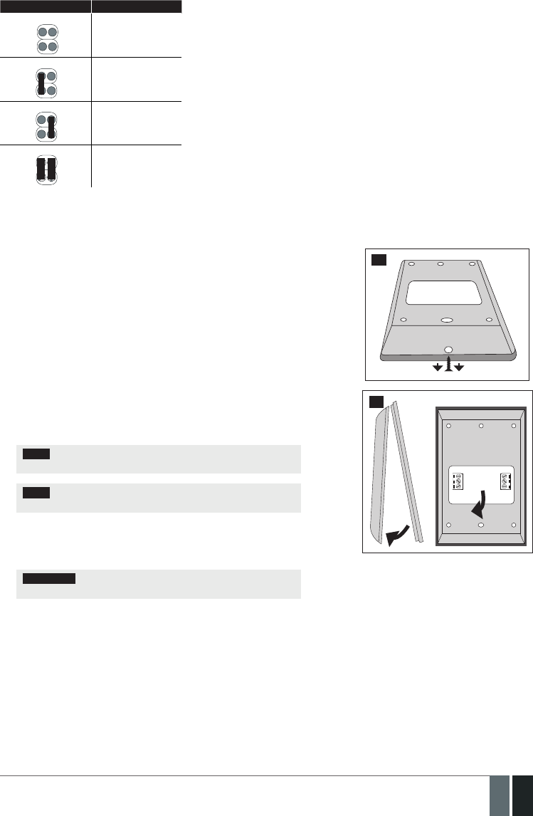
123
123EN
MANUAL ELDES ESIM364 V1.5
Jumper position Address
A0 A1 Keypad 1
A0 A1 Keypad 2
A0 A1 Keypad 3
A0 A1 Keypad 4
The address of each connected keypad is also indicated in ELDES Conguration Tool software.
32.1.1.2. Installation
1. Remove the screw located on the bottom side of the enclosure (see Fig. No.
43).
2. Detach keypad holder from EKB2 keypad by gently pulling the holder
towards yourself (see Fig. No. 44).
3. Fix the keypad holder on the wall using the screws. (see Fig. No. 45).
4. Disconnect ESIM364 main power supply and backup battery.
5. Wire up keypad terminals to ESIM364 alarm system respectively – Vin to
AUX+, COM to AUX-, Y to Y, G to G.
6. Connect a sensor and the resistor across Z1 and COM terminalss in accor-
dance with zone connection Type 1 or Type 2 (see 2.3.2. Zone Connec-
tion Types). As keypad zone Z1 is disabled by default, it can be enabled
by SMS, ELDES Conguration Tool, EKB2, EKB3 and EKB3W keypad. Keypad
zone Z1 must be enabled and resistor connected even if the tamper button
alone is required (see Fig. No. 42).
NOTE: Keypad zone connection type can dier from selected on-board
zone connection type.
NOTE: ATZ mode is NOT supported by keypad zones. ATZ mode is
ineective for keypad zones when enabled.
7. Set the keypad address by putting the jumper on A0 and A1 pins (see
32.1.1.1.4 Keypad Address).
8. Fix the keypad into the holder.
ATTENTION: Before xing the keypad into the holder please , make
sure that the tamper button is properly pressed (see Fig. No. 42).
9. Screw in the bottom side of the enclosure. (see Fig. No. 43).
10. Power up ESIM364 alarm system.
11. EKB2 keypad is ready.
For more details on multiple keypad wiring, please refer to 3.2.7. RS485
43
44

124
124 EN MANUAL ELDES ESIM364 V1.5
45
VIN
YGAUX- AUX+
EKB2
ESIM364
COM
Z1
G
Y
COM
5,6kΩ
46
32.1.1.3. Visual and Audio Indications
EKB2 can be used even in dark premises as the LCD screen and keys are illuminated continuously. The illumination level lowers down if 3 min-
utes after the last key-touch expires while the system is disarmed. In case of alarm, the keypad illumination level is boosted and stays in this
state until the system is disarmed.
The built-in buzzer uses two types of sound signals – three short beeps and one long beep. Three short beeps stand for successfully carried
out conguration, one long beep – for invalid conguration. In addition, the buzzer emits short beeps in case of alarm and exit/entry delay
countdown.
32.1.1.4. EKB2 Zone and Tamper
Keypad EKB2 has one wired zone Z1 and one tamper button. By default, the keypad zone Z1 is disabled. The keypad zone can be enabled by
SMS, EKB2 keypad, EKB3 keypad, EKB3W keypad and ELDES Conguration Tool software (see 14.9. Disabling and Enabling Zones). When
Z1 is enabled, it operates like any other system zone, therefore a sensor can be connected to it. In addition, Z1 and COM terminals must be
connected with resistor of 5,6k nominal.
The tamper button is intended for monitoring the enclosure status of EKB2, therefore the system causes alarm if the enclosure is illegally
opened. Keypad zone Z1 must be enabled and resistor connected even if the tamper button alone is required.
32.1.1.5. Icons and Messages
Icon / Message Description
Chime - Delay zone violated when system
is disarmed.
Exit delay countdown initiated.
System is armed and menu is locked.
System is disarmed and menu is unlocked
+ CONFIGURATION
MODE
Conguration mode activated.
BURGLARY ALARM Delay, Instant or Follow zone violated
when system is armed.
Icon / Message Description
24 ALARM 24H zone violated.
FIRE ALARM Fire zone violated.
TAMPER ALARM Tamper violated
READY System is ready to be armed.
NOT READY System is not ready to be armed – one or
more zones / tampers violated.
ARMED System is armed (optional feature).
STAY Stay mode activated
BYP System armed in Stay mode
FLT One or more system faults are present

125
125EN
MANUAL ELDES ESIM364 V1.5
32.1.1.6. Menu Tree
HOME SCREEN VIEW
BYPASS
BYP VIOLATED ZONES
Z1-zone-name...
Z12-zone-name
Z13-zone-name...
Z76-zone-name
Z13-zone-name...
Z76-zone-name
Z13-zone-name...
Z76-zone-name
Z13-zone-name...
Z76-zone-name
[1] part-name...
[4] part-name ZONE 1... 76
yyyy-mm-dd hr:mn
1. tm.p C (PRIM) | (SEC)... 8. tm.p C
ENTER USER PSW
ENTER ADMIN PSW
BATTERY DEAD/MISS | BATTERY FAILED | SIREN FAILED
| GSM CONNECT FAILED | GSM/GPRS ANTENNA FAILED |
VIOLATED TAMPER | MAIN POWER LOSS | DATE/TIME NOT
SET | LOW BATTERY | WLESS SIGNAL LOST
TAMPER 1... 76
DISABLE | ENABLE
DISABLE | ENABLE
DISABLE | ENABLE
DISABLE | ENABLE
DISABLE | ENABLE
DISABLE | ENABLE
[0001... 9999]
[0000... 9999]
[0000... 9999]
N/A | 1... 10
N/A | 1... 10
pv
pv
UNBYPASS | BYPASS
UNBYPASS | BYPASS
UNBYPASS | BYPASS
UNBYPASS | BYPASS
UNBYPASS | BYPASS
P1 P2 OK
uuuu
BYPASS LIST 1
BYPASS LIST 2
BYPASS LIST 3
BYPASS LIST 4
BYPASS LIST 5
CONFIGURATION
WIRELESS DEVICES 1... 2
IBUTTON KEYS
NEW IBUTTON
IBUTTON 1... 16
wless-dev wless-id
BATTERY
SIGNAL
ID
ERROR RATE
PARTITION
FW RELEASE
REMOVE
VIOLATED ZONES
DATE/TIME SETTINGS
TEMP SENSORS INFO
VIEW EVENT LOG uuuu
aaaa
PRIMARY SETTINGS
CALL/SMS SETTINGS
PASSWORDS
SMS PASSWORD
DURESS PASSWORD
SGS PASSWORD
REMOVE PASSWORD
ADMIN PASSWORD
USER PASSWORDS
USER PASSWORD 1... 16
USER PASSWORD 17... 30
PASSWORD
PASSWORD
PARTITION
PARTITION
USERS
SEND ARM/DARM ALL
SEND ALARM SMS ALL
CALL IN CASE ALARM
CTRL FROM ANY NUM
USER 1... 10
ttteeellnnuumm
PHONE NUMBER
PARTITION
SEND ARM/DARM SMS
FAULTS
VIOLATED TAMPERS
Continued in next page
[0000... 9999]
[0000... 9999]
pv
pv
ENTER USER PSW

126
126 EN MANUAL ELDES ESIM364 V1.5
ENGLISH
[0... 23]
[1... 65535]
[1... 65535]
[1... 65535]
[1... 65535]
[0... 600]
[1... 10]
[0... 65535]
[0... 65535]
seconds
seconds
seconds
seconds
seconds
seconds
minutes
[0... 99]
°C
°C
yyyy-mm-dd hr:mn
INTERIOR FOLLOWER | INSTANT |
24-HOUR | DELAY | FIRE | PANIC/SILENT
INTERIOR FOLLOWER | INSTANT |
24-HOUR | DELAY | FIRE | PANIC/SILENT
INTERIOR FOLLOWER | INSTANT |
24-HOUR | DELAY | FIRE | PANIC/SILENT
SMS LANGUAGE
ZONES
DATE/TIME SETTINGS
ONBOARD ZONES
WIRELESS ZONES 1... 4
KEYPAD ZONES
EPGM1 ZONES 1-16
WIRELESS ZONE 13... 76
1ST... 4TH KEYPAD ZONE
EPGM1 ZONE 1... 16
NAME
NAME
NAME
STATUS
STATUS
STATUS
TYPE
TYPE
TYPE
ENTRY DELAY
ENTRY DELAY
ENTRY DELAY
STAY
STAY
STAY
TAMPER NAME
TAMPER NAME
TAMPER NAME
PARTITION
PARTITION
PARTITION
FORCE
FORCE
FORCE
ZONE 1... 12
STATUS
ENTRY DELAY
TYPE
NAME
INFO SMS SCHEDULER
TEMP SENSORS
EXIT DELAY
SIREN SETTINGS
MAIN POWER STATUS
KEYPAD PARTITION
GSM AUDIO
MICROPHONE GAIN
SPEAKER LEVEL
KEYPAD PARTITION
EKB3W PARTITION EKB3W wless-id | NOT USED
[1] EKB2 | NOT USED...
[4] EKB2 | NOT USED
[1] EKB3 | NOT USED...
[4] EKB3 | NOT USED
PARTITION 1... 4
TEMPERATURE SENS 1... 8
PRIMARY
TEMP SENS
PRIMARY TEMP SENS
ALARM DURATION
LOSS DELAY
RESTORE DELAY
PARTITION SWITCH
BELL SQUAWK
SRN IF WLESS LOSS
EWS2 LED
EWF1 SIREN INTERC.
EVENT LOG
TEMP. MIN
TEMP. MAX
NAME
[-55... +125]
[-55... +125]
FREQUENCY (DAYS)
TIME
Continued from previous page
PRIMARY SETTINGS
CONFIGURATION
DISABLE | ENABLE
DISABLE | ENABLE
DISABLE | ENABLE
DISABLE | ENABLE
DISABLE | ENABLE
DISABLE | ENABLE
DISABLE | ENABLE
DISABLE | ENABLE
DISABLE | ENABLE
DISABLE | ENABLE
pv
pv
pv
DISABLE |
ENABLE INTERIOR FOLLOW-
ER | INSTANT | 24-
HOUR | DELAY | FIRE
| PANIC/SILENT
1... 8 PRIM | SEC
| CONNECTED
1... 8 PRIM | SEC | CONNECTED
DISABLE | ENABLE
DISABLE | ENABLE
DISABLE | ENABLE
PARTITION 1... 2
[0... 15]
[0... 100]
PARTITION
1... 4
PARTITION
1... 2
DISABLE | ENABLE
DISABLE | ENABLE
Continued in next page

127
127EN
MANUAL ELDES ESIM364 V1.5
ZONES
CONFIGURATION
Continued from previous page
[1... 65535]
[1... 65535]
seconds
seconds
INTERIOR FOLLOWER | INSTANT |
24-HOUR | DELAY | FIRE | PANIC/SILENT
EPGM1 ZONES 17-32
ATZ MODE
ZONE TYPE:6-ZONE M
MS SETTINGS
ACCOUNT
DELAY LAST ATTEMPT
MS MODE
DATA MESSAGES 1
DATA MESSAGES 2
MAIN POWER L/R EV
ARM/DARM SGS EVENT
BATTERY FAILED
SIREN FAIL/REST EV
TEST EVENT
DATE/TIME NOT SET
PA/SIL ALM/REST EV
GSM/GPRS ANT FAIL/REST
FIRE ALM/REST EV
KEYPAD FAIL/REST
VOICE CALLS/SMS ST
ATTEMPTS
TEL. NUMBER1
TEL. NUMBER2
TEL. NUMBER3
LOW BATTERY EVENT
TEMP LOW EVENT
BURGLR ALM/REST EV
ARM/DARM DURESS EV
ARM/DISARM EVENT
ARM/DARM STAY EV
BATTERY DEAD/MISS
TAMPER ALM/REST EV
GSM CONNECT FAILED
SYSTEM STARTED EV
SYSTEM SHUTDOWN EV
24H ALM/REST EVENT
GPRS CONNECT FAIL
TEMP HIGH EVENT
WLESS SIGN L/R EV
ZONE TYPE:ATZ MODE
ARM/DISARM BY ZONE
PGM OUTPUTS
WIRELESS DEVICES 1... 2
GPRS SETTINGS
SERVER IP LOCAL PORT
DNS1 APN
DNS2 USER
PROTOCOL PASSWORD
SERVER PORT PROFILE
wless-dev wless-id
BATTERY SIGNAL ERROR RATE FW RELEASE
ONBOARD OUTPUTS
WIRELESS OUTPUTS 1... 4WIRELESS OUTPUT 13... 76
OUTPUT 1... 12
NAME
NAME
STATUS
STATUS
USING EPGM8
CHIME
EPGM1 ZONE 17... 32
NAME
STATUS
TYPE
ENTRY DELAY
STAY
TAMPER NAME
PARTITION
FORCE
DISABLE | ENABLE
DISABLE | ENABLE
DISABLE | ENABLE
TYPE 1... 3
TYPE 4... 5
N/A / ZONE 1... 12
DISABLE | ENABLE
DISABLE | ENABLE
DISABLE | ENABLE
DISABLE
| ENABLE
DISABLE | ENABLE
DISABLE | ENABLE
DISABLE | ENABLE
DISABLE | ENABLE
DISABLE | ENABLE
DISABLE | ENABLE
DISABLE | ENABLE
DISABLE | ENABLE
DISABLE | ENABLE
DISABLE | ENABLE
[0.0.0.0]
[0.0.0.0]
[0.0.0.0]
TCP | UDP
[1... 65535]
[1... 65535]
DISABLE | ENABLE
DISABLE | ENABLE
[1... 10]
ttteeellnnuumm
ttteeellnnuumm
ttteeellnnuumm
15 digits
15 digits
15 digits
DISABLE | ENABLE
DISABLE | ENABLE
DISABLE | ENABLE
DISABLE | ENABLE
DISABLE | ENABLE
DISABLE | ENABLE
DISABLE | ENABLE
DISABLE | ENABLE
DISABLE | ENABLE
DISABLE | ENABLE
DISABLE | ENABLE
DISABLE | ENABLE
DISABLE | ENABLE
DISABLE | ENABLE
pv
Continued in next page
DISABLE | ENABLE

128
128 EN MANUAL ELDES ESIM364 V1.5
DISABLE | ENABLE
DISABLE | ENABLE
Continued from previous page
MS SETTINGS
CONFIGURATION
DISABLE | ENABLE
DISABLE | ENABLE
DISABLE | ENABLE
DISABLE | ENABLE
DISABLE | ENABLE
DISABLE | ENABLE
DISABLE | ENABLE
DISABLE | ENABLE
DISABLE | ENABLE
DISABLE | ENABLE
DISABLE | ENABLE
DISABLE | ENABLE
DISABLE | ENABLE
DISABLE | ENABLE
DISABLE | ENABLE
uuuu
PSTN SETTINGS
SMS MESSAGES 1
SMS MESSAGES 2
RESET TO DEFAULT
SYS ARMED EVENT
DATE/TIME NOT SET
SYS DISARMED EVENT
GSM CONNECT FAILED
GENERAL ALARM EV
GSM/GPRS ANT FAIL/REST
MAIN POWER L/R EV
TAMPER ALARM
BATTERY FAILED
KEYPAD FAILED
BATTERY DEAD/MISS
TEMP INFO EVENT
LOW BATTERY EVENT
SYSTEM STARTED EV
SIREN FAIL/REST EV
PERIOD INFO SMS EV
WLESS SIGN LOSS EV
GPRS SETTINGS
PRIMARY CONNECTION
BACKUP CONNECTION1
BACKUP CONNECTION2
BACKUP CONNECTION3
BACKUP CONNECTION4
BACKUP CONNECTION5
CSD SETTINGS
ATTEMPTS
GPRS ATTEMPTS
ATTEMPTS
TEL. NUMBER1
UNIT ID
TEL. NUMBER1
TEL. NUMBER2
TEL. NUMBER3
TEL. NUMBER4
TEL. NUMBER5
TEL. NUMBER2
TEST PERIOD
TEL. NUMBER3
[1... 10]
[0... 255]
GPRS | VOICE CALLS | RS485 | CSD | PSTN | SMS | N/A
GPRS | VOICE CALLS | RS485 | CSD | PSTN | SMS | N/A
GPRS | VOICE CALLS | RS485 | CSD | PSTN | SMS | N/A
GPRS | VOICE CALLS | RS485 | CSD | PSTN | SMS | N/A
GPRS | VOICE CALLS | RS485 | CSD | PSTN | SMS | N/A
GPRS | VOICE CALLS | RS485 | CSD | PSTN | SMS | N/A
[1... 10]
ttteeellnnuumm
[0000... 9999]
ttteeellnnuumm
ttteeellnnuumm
ttteeellnnuumm
ttteeellnnuumm
ttteeellnnuumm
ttteeellnnuumm
[0... 65535]
ttteeellnnuumm
15 digits
15 digits
15 digits
15 digits
15 digits
15 digits
15 digits
seconds
ENTER USER PSW
15 digits

129
129EN
MANUAL ELDES ESIM364 V1.5
32.1.2. EKB3 - LED Keypad
EKB3 is a LED keypad intended for using with ESIM364 alarm system.
Main EKB3 features:
• Alarm system arming and disarming (see 12.4. EKB3 Keypad and User Password).
• Arming and disarming in Stay mode (see 15. STAY MODE).
• System parameter conguration (see 5. CONFIGURATION METHODS).
• PGM output control (see 18.4. Turning PGM Outputs ON and OFF).
• Visual indication by LED indicators (see 32.1.2.3. Visual and Audio Indications).
• Audio indication by built-in buzzer (see 32.1.2.3. Visual and Audio Indications).
• Keypad partition switch (see 23.3. Keypad Partition and Keypad Partition Switch).
The system conguration by EKB3 keypad is performed by activating the Conguration mode (see 5. CONFIGURATION METHODS) and en-
tering the required parameters & values. ESIM364 system allows to connect up to 4 EKB3 keypads.
32.1.2.1. Technical Specications
32.1.2.1.1 Electrical & Mechanical Characteristics
Power Supply 12-14V 150mA max
Maximum Keypad Connection Cable Length 100 m.
Dimensions 140x100x18mm
Humidity 0-90% RH @ 0... +40 °C (non-condensing)
Range of Operating Temperatures -30...+55ºC
32.1.2.1.2 LED Functionality
ARMED Steady ON - alarm system is armed / exit delay in progress; ashing - Conguration mode activated
READY Steady ON - system is ready – no violated zones and tampers
SYSTEM Steady ON - system faults; ashing - violated high-numbered zone (-s)
BYPS Steady ON - zone bypass mode
1-12 Steady ON - violated zone Z1-Z12
32.1.2.1.3 Keys Functionality
[BYPS] Zone bypass mode
[CODE] Additional options - system fault indication / violated high-numbered zone indication / violated tamper indication
[*] Cancel command
[#] Conrm (enter) command
[0] ... [9] Command typing
[1] ... [4] Keypad partition switch / armed partition indication / violated partition indication
[0] 4 partitions arming
[STAY] Manual system arming in Stay mode
[INST] N/A
32.1.2.1.4 Connector Functionality
AUX+ Positive power supply terminal
AUX- Negative power supply terminal
GRS485 interface for communication (green wire)
YRS485 interface for communication (yellow wire)
COM Common terminal for Z1
Z1 Security zone terminal
Z2 N/A
3, 2 Keypad address pins
1N/A

130
130 EN MANUAL ELDES ESIM364 V1.5
1 2 3
4 5 6
7
ARMED
READY
SYSTEM BYPS
A B
1
2
3
4
5
6
7
8
9
10
11
12
8 9
*0 #
STAY
BYPS
INST
CODE
FRONT SIDE
Z2 Z1
COM Y
G
AUX-
AUX+
TAMPER
3 2 1
BACK SIDE
47
32.1.2.1.5 Keypad Address
Pins 3 and 2 located on the back side of the keypad are intended to set keypad address. The keypad address is set by putting the jumper (-s)
on the pins. ESIM364 system allows to connect up to 4 EKB3 keypads - each set under dierent address. Jumper combinations for dierent
keypad address conguration are indicated in the table below.
Address Conguration
Jumper position Address
3 2 1
Keypad 1
3 2 1
Keypad 2
3 2 1
Keypad 3
3 2 1
Keypad 4
NOTE: Pins 1 are inactive.
The address of each connected keypad is also indicated in ELDES Conguration Tool software.
32.1.2.2. Installation
1. Detach keypad holder from EKB3 keypad . Keypad holder detach points are marked with arrows (see Fig. No. 48)..
BACK SIDE
DOWN SIDE
48

131
131EN
MANUAL ELDES ESIM364 V1.5
2. Disconnect alarm system ESIM364 power supply and backup battery before connecting the wires.
Z2 Z1
COM Y
G
AUX-
AUX+
EKB3
ESIM364
YGAU X- AUX+
5,6kΩ
49
3. Wire up keypad terminals to ESIM364 alarm system respectively – AUX+ to AUX+, AUX- to AUX- , Y to Y, G to G. (see Fig. No. 49).
4. Connect a sensor and the resistor across Z1 and COM terminalss in accordance with zone connection Type 1 or Type 2 (see 2.3.2. Zone
Connection Types). As keypad zone Z1 is disabled by default, it can be enabled by SMS, ELDES Conguration Tool, EKB2, EKB3 and EK-
B3W keypad. Z2 terminal is permanently inactive. Keypad zone Z1 must be enabled and resistor connected even if the tamper button
alone is required (see Fig. No. 47).
NOTE: Keypad zone connection type can dier from selected on-board zone connection type.
NOTE: ATZ mode is NOT supported by keypad zones. ATZ mode is ineective for keypad zones when enabled.
5. Set the keypad address by combining DIP switch positions (see 32.1.2.1.5 Keypad Address).
6. Inx the keypad into the holder (see Fig. No. 48).
ATTENTION: Before xing the keypad into the holder please , make sure that the tamper is properly pressed (see Fig. No. 47).
7. Power up ESIM364 alarm system.
8. EKB3 keypad is ready.
For more details on multiple keypad wiring, please refer to 3.2.7. RS485.
32.1.2.3. Visual and Audio Indications
EKB3 keys have a LED back-light, therefore it is possible to use this keypad even in dark premises. The back-light lasts for 3 minutes after the
last key-stroke while the system is disarmed. In case of alarm, the keypad back-light turns ON and lasts until the system is disarmed.
The built-in buzzer uses two types of sound signals – three short beeps and one long beep. Three short beeps stand for successfully carried
out conguration command, one long beep – for invalid conguration command. In addition, the buzzer emits short beeps in case of alarm and
exit/entry delay countdown.
32.1.2.4. EKB3 Zone & Tamper
Keypad EKB3 has one wired zone Z1 and one tamper button. By default, the keypad zone Z1 is disabled. The keypad zone can be enabled by
SMS, EKB2 keypad, EKB3 keypad, EKB3W keypad and ELDES Conguration Tool software (see 14.9. Disabling and Enabling Zones). Zone
Z1 is enabled, it operates like any other system zone, therefore a sensor can be connected to it. In addition, Z1 and COM terminals must be
connected with resistor of 5,6k nominal.
The tamper button is intended for monitoring the enclosure status of EKB3, therefore the system causes alarm if the enclosure is illegally
opened. Keypad zone Z1 must be enabled and resistor connected even if the tamper button alone is required.

132
132 EN MANUAL ELDES ESIM364 V1.5
32.1.3. EPGM1 - Hardwired Zone & PGM Output Expansion Module
EPGM1 is a hardwired zone & PGM output expansion module intended for using with ELDES alarm systems.
Main EPGM1 features:
• Hardwired zone expansion. Each module adds 16 additional zones;
• Hardwired PGM output expansion. Each module adds 2 additional PGM outputs for electrical appliance connection;
• Up to 32 hardwired zone and up to 4 hardwired PGM output expansion.
32.1.3.1. Technical Specications
32.1.3.1.1 Electrical & Mechanical Characteristics
Power Supply 10-24V 100mA max without auxiliary equipment.
Number of Digital Inputs 16
Nominal Resistance 5,6k
Number of PGM Outputs 2
Maximum PGM Output Current 250 mA
EPGM1 PGM Output Circuit 1 R OUT Open collector output.
Output is pulled to
COM when turned on.
Maximum Commuting PGM Output Values Voltage – 30V; current 250mA
AUX: Auxiliary Equipment Power Supply 13,8V 500 mA max
Dimensions 118 x 47 mm
Humidity 0-90% RH @ 0... +40 °C (non-condensing)
Range of Operating Temperatures -20...+55ºC
32.1.3.1.2 LED and Pin Functionality
C2, C1 PGM output C1, C2 status – on/o
Z1 - Z16 Zone Z1 - Z16 state – alarm/restore
STATUS EPGM1 micro-controller status
A0 EPGM1 module address pins
A1 N/A
A2 N/A
32.1.3.1.3 Connector Functionality
C1, C2 PGM output terminals
Z1 - Z16 Security zone terminals
AUX- Negative power supply terminal for auxiliary equipment
AUX+ Positive power supply terminal for auxiliary equipment
Y RS485 interface for communication (yellow wire)
G RS485 interface for communication (green wire)
COM Negative power supply terminal
DC+ Positive power supply terminal

133
133EN
MANUAL ELDES ESIM364 V1.5
C2 C1
C1 Z1 Z2C2 COM COM Z3 Z4COM Z5 Z6COM Z7 Z8COM Z9 Z10COM Z11 Z12COM Z13 Z14COM Z15 Z16COM COM
-AUX DC+ Y G+
Z1 Z2 Z3 Z4 Z5 Z6 Z7 Z8 Z9 Z10 Z11 Z12 Z13Z14 Z15 Z16
STATUS
A1
A0
A2
50
C2 C1
C1 Z1 Z2C2 COM COM Z3 Z4COM Z5 Z6COM Z7 Z8COM Z9 Z10COM Z11 Z12COM Z13 Z14COM Z15 Z16COM COM
-AUX DC+ Y G+
Z1 Z2 Z3 Z4 Z5 Z6 Z7 Z8 Z9 Z10 Z11 Z12Z13 Z14 Z15Z16
STATUS
Z1
Z2
RELAY
MODULE
EPGM1
Z3
Z4
Z5
Z6
Z7
Z8
Z9
Z10
Z11
Z12
Z13
Z14
Z15
Z16
5,6 kΩ
5,6 kΩ
5,6 kΩ
5,6 kΩ
5,6 kΩ
5,6 kΩ
5,6 kΩ
5,6 kΩ
5,6 kΩ
5,6 kΩ
5,6 kΩ
5,6 kΩ
5,6 kΩ
5,6 kΩ
5,6 kΩ
5,6 kΩ
Y
G
AUX-
AUX+
ESIM364
A1
A0
A2
51
32.1.3.1.4 EPGM1 Address
ESIM364 system allows to connect up to 2 EPGM1 modules - each set under dierent address. The module address can be set by putting
or removing the jumper from the A0 pins implemented in horizontal position (see Fig. No. 50). Jumper combinations for dierent EPGM1
module address conguration are indicated in the table below.
Address Conguration
Jumper position Address
A0 Module 1
A0 Module 2

134
134 EN MANUAL ELDES ESIM364 V1.5
32.1.3.2. Installation
1. Disconnect ESIM364 alarm system main power supply and backup battery.
2. Connect EPGM1 DC+ terminal to ESIM364 AUX+ terminal, EPGM1 COM terminal to ESIM364 AUX- terminal, EPGM1 Y and G termianls
must be connected to ESIM364 Y and G terminals respectively (see Fig. No. 51).
3. Connect the resistors and sensors to EPGM1 module according to zone connection Type 1, Type 2 or Type 3. See 2.3.2 Zone Connec-
tion Types.
4. Set the EPGM1 module address by putting or removing the jumper from the A0 pins (see 32.1.3.1.4. EPGM1 Address).
5. Power up ESIM364 system.
6. Upon successful startup indicator STATUS should be blinking indicating successful EPGM1 operation.
7. EPGM1 is ready for use with ESIM364 alarm system.
NOTE: EPGM1 zone connection type can dier from selected on-board zone connection type.
NOTE: ATZ mode is NOT supported by EPGM1 zones. ATZ mode is ineective for EPGM1 zones when enabled for on-board zones.
For more details on multiple EPGM1 module wiring, please refer to 3.2.7. RS485
32.2. 1-Wire Interface
1-Wire interface is used for the system to communicate with an iButton key reader and up to 8 temperature sensors. 1-Wire interface COM
and DATA terminals are ground and data respectively. When connecting single or multiple temperature sensors, the +5V terminal must be
used along.
For more details on 1-Wire device wiring, please refer to 32.2.1 iButton Key Reader and Buzzer
32.2.1. iButton Key Reader and Keys
The iButton key is a chip enclosed in a stainless steel tab usually implemented in a small plastic holder. Each iButton key holds a unique
identity code (ID) which is used for alarm system ESIM364 arming and disarming procedure.
Main iButton features:
• Up to 16 iButton keys per alarm system unit ESIM364;
• Communication via 1-Wire interface.
32.2.1.1. Technical Specications
32.2.1.1.1 Electrical & Mechanical Characteristics
Supported iButton Key Model Maxim/Dallas DS1990A
Communication Interface 1-Wire
Maximum Cable Length for 1-Wire Communication up to 30 meters
32.2.1.1.2 Installation
1. Disconnect ESIM364 alarm system main power supply and backup battery.
2. Connect iButton key reader contact wires to 1-Wire interface on ESIM364 alarm system: COM and DATA terminals respectively.
COM
DATA
iButton
key reader
52
3. Power up ESIM364 alarm system.
4 iButton® key reader is ready for use with ESIM364 alarm system.
For more details on iButton key management, please refer to 11. iBUTTON KEYS.

135
135EN
MANUAL ELDES ESIM364 V1.5
32.3. Modules Interface
32.3.1. EPGM8 - Hardwired PGM Output Expansion Module
EPGM8 is a PGM output expansion module intended for using with alarm system ESIM364. This module allows to connect up to additional
8 electrical appliances.
Main EPGM8 features:
• PGM output expansion adding 8 additional PGM outputs;
• Compatible with ESIM364 alarm system
32.3.1.1. Technical Specications
32.3.1.1.1 Electrical & Mechanical Characteristics
Power Supply 10-24V 100mA max
Number of PGM Outputs 8
EPGM8 PGM Output Circuit 1 R OUT Open collector output.
Output is pulled to COM
when turned on.
Maximum Commuting PGM Output Values Voltage – 30V; current 500mA
Dimensions 40 x 55 x 15 mm
Humidity 0-90% RH @ 0... +40 °C (non-condensing)
Range of Operating Temperatures -20...+55ºC
32.3.1.1.2 Connector Functionality
D1 - D8 PGM output terminals
12V Positive power supply terminal
GND Negative power supply terminal
D1 D2 D3 D4 D5 D6 D7 D8
12V GND
53
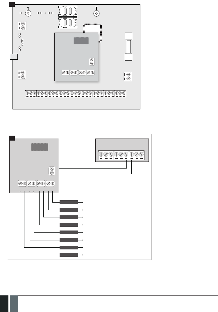
136
136 EN MANUAL ELDES ESIM364 V1.5
32.3.1.2. Installation
1. Disconnect ESIM364 alarm system main power supply and backup battery.
2. Insert EPGM8 pins into appropriate ESIM364 alarm system slots (see Fig. No. 54)
G S M
MO DE M
ANTW-LESS GSM/GPRS ANT
TIP
FUSE F1
RING
DEF
PRG
USB
AK U +
AK U -
C 2
C 3
C 3
C 4
C 4
C 1
S TA T
NE TW
C O M
BELL-
BELL+
G
Y
C2
AUX-
AUX+
AC /DC
AC /DC
Z1
C O M
Z2
Z3
C O M
Z4
DA T A
+5V
M IC -
MIC +
BU Z -
C1
BU Z +
C O M
C O M
Z6
Z5
3A
MODULES
OPEN
OPEN
D1 D2 D3 D4 D5 D6 D7 D8
12V GND
EPGM8
ESIM364
54
3. Connect EPGM8 12V positive power supply terminal with ESIM364 alarm system AUX+ terminal and EPGM8 GND terminal with
ESIM364 alarm system AU X- terminal. (see Fig. No. 55).
4. Connect the electrical appliances to D1 – D8 PGM outputs. (see Fig. No. 55).
ESIM364
D1 D2 D3 D4 D5 D6 D7 D8
12V GND
TO AUX+
TO AUX+
TO AUX+
TO AUX+
TO AUX+
TO AUX+
TO AUX+
TO AUX+
El. Appliance 1
El. Appliance 2
El. Appliance 3
El. Appliance 4
El. Appliance 5
El. Appliance 6
El. Appliance 7
El. Appliance 8
AUX- AUX+
55
5. Power up ESIM364 alarm system.
6. Enable EPGM8 mode using EKB2, EKB3, EKB3W keypads or ELDES Conguration Tool software. For more details, please refer to
software’s HELP section or 18.2.1. EPGM8 Mode.
7. EPGM8 is ready for use with ESIM364 alarm system.

137
137EN
MANUAL ELDES ESIM364 V1.5
32.3.2. EA1 – Audio Output Module
EA1 audio output module enables a duplex audio connection for ESIM364 alarm system.
Main EA1 features:
• Two-way voice conversation during a phone call;
• Possibility to connect headphones or desktop speakers.
32.3.2.1. Technical Specications
• 3,5 mm female jack
• Dimensions: 35 x 33 x 12 mm
32.3.2.2. Installation
1. Disconnect ESIM364 alarm system main power supply and backup battery.
2. Insert EA1 pins into appropriate ESIM364 alarm system slots.
G S M
MO DE M
ANTW-LESS GSM/GPRS ANT
TIP
FUSE F1
RING
DEF
PRG
USB
AK U +
AK U -
C 2
C 3
C 3
C 4
C 4
C 1
S TA T
NE TW
C O M
BELL-
BELL+
G
Y
C2
AUX-
AUX+
AC /DC
AC /DC
Z1
C O M
Z2
Z3
C O M
Z4
DA T A
+5V
M IC -
MIC +
BU Z -
C1
BU Z +
C O M
C O M
Z6
Z5
3A
MODULES
OPENOPEN
EA1
ESIM364
56
3. Connect headphones or desktop speakers to EA1 3,5 mm female jack.
EA1
57
4. Power up ESIM364 alarm system.
5. EA1 is ready for use with ESIM364 alarm system.

138
138 EN MANUAL ELDES ESIM364 V1.5
32.3.3. EA2 – Audio Output Module with Amplier
EA2 audio output module enables a duplex audio connection for ESIM364 alarm system.
Main EA2 features:
• Two-way voice conversation during a phone call;
• Possibility to connect a speaker.
32.3.3.1. Technical Specications
• 1W 8 audio amplier
• Dimensions: 41 x 40 x 24 mm
32.3.3.2. Installation
1. Disconnect ESIM364 alarm system main power supply and backup battery.
2. Insert EA2 pins into appropriate ESIM364 alarm system slots.
G S M
MO DE M
ANTW-LESS GSM/GPRS ANT
TIP
FUSE F1
RING
DEF
PRG
USB
AK U +
AK U -
C 2
C 3
C 3
C 4
C 4
C 1
S TA T
NE TW
C O M
BELL-
BELL+
G
Y
C2
AUX-
AUX+
AC /DC
AC /DC
Z1
C O M
Z2
Z3
C O M
Z4
DA T A
+5V
M IC -
MIC +
BU Z -
C1
BU Z +
C O M
C O M
Z6
Z5
3A
MODULES
OPENOPEN
EA2
ESIM364
58
3. Connect a speaker to EA2 Speaker terminals.
EA2
59
4. Power up ESIM364 alarm system.
5. EA2 is ready for use with ESIM364 alarm system.

139
139EN
MANUAL ELDES ESIM364 V1.5
33. ELDES WIRELESS DEVICES
33.1. EKB3W - Wireless LED Keypad
EKB3W is a wireless LED keypad intended to use with ELDES alarm systems.
Main EKB3W features:
• Alarm system arming and disarming (see 12.5. EKB3W Keypad and User Password).
• Arming and disarming in Stay mode (see 15. STAY MODE).
• System parameter conguration (see 5. CONFIGURATION METHODS).
• PGM output control (see 18.4. Turning PGM Outputs ON and OFF).
• Visual indication by LED indicators (see 33.1.5. Visual and Audio Indications).
• Audio indication by built-in buzzer (see 33.1.5. Visual and Audio Indications).
• Keypad partition switch (see 23.3. Keypad Partition and Keypad Partition Switch).
The system conguration by EKB3W keypad is performed by activating the Conguration mode (see 5. CONFIGURATION METHODS) and
entering the required parameters & values. ESIM364 system allows to connect up to 4 EKB3W keypads.
33.1.1. Technical Specications
33.1.1.1. Electrical & Mechanical Characteristics
Battery Type 1,5V Alkaline AAA type
Number of Batteries 3
Battery Operation Time ~12 months*
Wireless Transmitter-Receiver Frequency 868 Mhz (EU version) / 915 Mhz (US version)
Range of Operating Temperatures -30...+55ºC
Dimensions 140 x 100 x 18 mm
Humidity 0-90% RH @ 0... +40 °C (non-condensing)
Wireless Communication Range Up to 30 meters in premises; up to 150 meters in open areas
Compatible with Alarm Systems ELDES Wireless
* The operation time depends on dierent conditions and may vary.
33.1.1.2. LED Functionality
ARMED Steady ON - alarm system is armed / exit delay in progress; ashing - Conguration mode activated
READY Steady ON - system is ready – no violated zones and tampers
SYSTEM Steady ON - system faults; ashing - violated high-numbered zone (-s)
BYPS Steady ON - zone bypass mode
1-12 Steady ON - violated zone Z1-Z12
33.1.1.3. Keys Functionality
[BYPS] Zone bypass mode
[CODE] Additional options - system fault indication / violated high-numbered zone indication / violated tamper indication
[*] Cancel command / keypad partition switch (if enabled)
[#] Conrm (enter) command
[0] ... [9] Command typing
[STAY] Manual system arming in Stay mode
[INST] N/A

140
140 EN MANUAL ELDES ESIM364 V1.5
33.1.1.4. Main Unit & Connector Functionality
1 2 3
4 5 6
7
ARMED
READY
SYSTEM BYPS
A B
1
2
3
4
5
6
7
8
9
10
11
12
8 9
*0 #
STAY
BYPS
INST
CODE
FRONT SIDE
60
Z1 COM
TAMPER
BATTERY
+ -
BATTERY +-
BATTERY
+ - 5,6 kΩ
BACK SIDE
TAMPER Tamper-button for EKB3W
enclosure status monitoring
+ / - Battery slots
COM Common contact
Z1 Security zone terminal
33.1.2. Installation
1. Detach keypad holder from EKB3W front side . Keypad holder detach points are marked with arrows (see Fig. No. 61).
BACK SIDE
DOWN SIDE
61
2. Fix the keypad holder on the wall using the screws.
3. Connect a sensor and the resistor across Z1 and COM terminalss in accordance with zone connection Type 1 or Type 2 (see 2.3.2. Zone
Connection Types). As keypad zone Z1 is disabled by default, it can be enabled by SMS, ELDES Conguration Tool, EKB2, EKB3 and
EKB3W keypad. Keypad zone Z1 must be enabled and resistor connected even if the tamper button alone is required (see Fig. No. 60).
NOTE: Keypad zone connection type can dier from selected on-board zone connection type.
NOTE: ATZ mode is NOT supported by keypad zones. ATZ mode is ineective for keypad zones when enabled.
4. Remove the plastic tab inserted between one of the battery terminals and battery slot contacts (see Fig. No. 62).
62
ATTENTION: Before xing the keypad into the holder please , make sure that the tamper is properly pressed (see Fig. No. 60).
5. Bind the device to the alarm system by sending a corresponding command via SMS text message or using ELDES Conguration Tool soft-
ware. Please, refer to the software‘s HELP section or refer to 19.1. Binding, Removing and Replacing Wireless Devices for more
details. The system automatically informs about successful/unsuccessful binding process. If attempt to bind is unsuccessful, try to move
EKB3W closer to alarm system device and bind it again.
7. Upon the successful binding process, the built-in mini buzzer of EKB3W device provides 3 short beeps and the system automatically in-
forms about successful/unsuccessful binding process. If attempt to bind is unsuccessful, try to move EKB3W closer to alarm system device
and bind anew.
8. EKB3W keypad is ready for use.

141
141EN
MANUAL ELDES ESIM364 V1.5
NOTE: If you are unable to bind the wireless device please , restore the parameters of the wireless device to default and try again. See
33.1.6. Restoring Default Parameters for more details.
ATTENTION: The minimum wireless connection range between the wireless device and wireless antenna of ESIM364 system can be 0,5
meters.
33.1.3. EKB3W Zone & Tamper
Upon successful EKB3W wireless LED keypad contact binding process, the system adds 1 wireless Instant zone intended for wired sensor con-
nection. By default, the keypad zone Z1 is disabled. The keypad zone can be enabled by SMS, EKB2 keypad, EKB3 keypad, EKB3W keypad and
ELDES Conguration Tool. software (see 14.9. Disabling and Enabling Zones). When Z1 is enabled, it operates like any other system zone,
therefore a sensor can be connected to it. In addition, Z1 and COM terminals must be connected with resistor of 5,6k nominal.
In case of tamper violation, the alarm is caused regardless of system being armed or disarmed. There are 2 ways to detect tamper violation
on EKB3W:
• By tamper button. EKB3W has a built-in tamper button intended for monitoring the enclosure status. Once the enclosure of EKB3W is
illegally opened, the tamper button becomes unpressed. This action is followed by alarm which is sent by SMS text message and phone
call to the user (-s) by default. The SMS text message contains the violated tamper number.
• By wireless connection loss. The wireless connection loss between EKB3W and ESIM364 alarm system leads to alarm. The system
identies this event as a tamper violation and sends alarm by SMS text message and phone call to the user (-s) by default. The SMS text
message contains the violated tamper number and a star * character indicating wireless connection loss as a tamper alarm cause.
ATTENTION: The tamper will not operate if the wireless zone is disabled.
33.1.4. Battery Replacement
1. Open EKB3W enclosure.
2. Remove all 3 old batteries from the battery slots.
3. Postition the 3 new 1,5V alkaline AAA type batteries according to the appropriate battery slot positive/negative terminals indicated on
the PCB (printed-circuit-board) of EKB3W.
4. Insert the batteries into the battery slots.
5. Batteries replaced.
For more details, please refer to 33.1.2. Installation.
ATTENTION: Only 1,5V Alkaline AAA type batteries can be used. Install only new, high quality and unexpired batteries. Do not
mix the old batteries with the new ones.
ATTENTION: At least 1 battery must be removed if the device is not in use.
ATTENTION: In order to avoid re or explosion hazards, the system must be used only with approved battery. Special care must
be taken when connecting positive and negative battery terminals. Dispose old batteries only into special collection sites. Do not
charge, disassemble, heat or incinerate old batteries.
NOTE: The system sends an SMS message to a preset User 1 as soon as the battery level runs below 5%.
NOTE: The battery status can be monitored in real-time using ELDES Conguration Tool software.

142
142 EN MANUAL ELDES ESIM364 V1.5
33.1.5. Visual and Audio Indications
EKB3W keys have a LED back-light, which will be activated once any key is pressed. Due to battery power saving reasons, the back-light and
LED light last for 10 seconds after the last key-stroke.
The built-in buzzer uses two types of sound signals – three short beeps and one long beep. Three short beeps stand for successfully carried
out conguration command, one long beep – for invalid conguration command. The buzzer emits short beeps during exit delay. Due to ba-
ttery saving reasons the buzzer will beep during entry delay and in case of alarm only if the violated zone is of the associated EKB3W keypad.
NOTE: The keypad will not activate any LED indicators, nor the back-light if not bound to the system.
For more details, please refer to 33.1.7. Wireless Communication, Sleep Mode and Back-light Timeout
33.1.6. Restoring Default Parameters
1. Remove one battery from EKB3W.
2. Press and hold the [*] key.
3. Insert the battery back to EKB3W.
4. Hold the [*] key until LED READY starts ashing.
5. Wait until LED READY turns o and LED ARMED starts ashing.
6. Release the [*] key.
7. Parameters reset to default.
33.1.7. Wireless Communication, Sleep Mode and Back-light Timeout
Once the wireless device is bound, it will attempt to exchange data with ESIM364 system. The communication process follows this pattern:
1. Due to battery power saving reasons, most of the time EKB3W keypad operates in sleep mode and periodically wakes up (by default - ev-
ery 60 seconds) to transmit the supervision signal, identied as Test Time, to the ESIM364 system. However, when the keypad wakes up,
it will NOT activate its buzzer and/or the LED indicators.
2. When any EKB3W key is pressed, the keypad LED indicators and the back-light will activate for a set up period of time (by default - 10
seconds), identied as Back-light Timeout. During the Back-light Timeout, the Test Time will automatically switch to 2 seconds period
allowing to indicate system alarms, faults and arm/disarm process on the EKB3W keypad if it is assigned to the same partition as the one
that is violated or being armed/disarmed (see 23. PARTITIONS).
3. The Back-light timeout will expire after 10 seconds (by default) of EKB3W idling. When the Back-light Timeout expires, the keypad will
light OFF the LED indicators and the back-light and return to sleep mode. Meanwhile:
a) if a zone or tamper, which is of the associated EKB3W keypad, is violated, EKB3W will instantly wake up and initiate the Back-light Tim-
eout. Meanwhile the keypad buzzer will emit short beeps and the LED indicators will light ON indicating the violated zone or tamper
number.
b) if a zone or tamper, which is not of the associated EKB3W keypad, is violated, EKB3W keypad will NOT wake up and will NOT initiate the
Back-light Timeout as well as the buzzer will NOT emit short beeps and the LED indicators will NOT light ON.
To set a dierent Back-light Timeout value, please refer to the following conguration method:
Set Back-light
Timeout
Cong
Tool This operation may be carried out from the PC using the ELDES Conguration Tool software.
For more details and how to set a dierent Test Time value, please refer to 19. WIRELESS DEVICES.
NOTE: Even if Back-light Timeout has expired, the character will be considered as type in once the appropriate EKB3W key is pressed.

143
143EN
MANUAL ELDES ESIM364 V1.5
33.2. EW1 - Wireless Zone & PGM Output Expansion Module
Main EW1 features:
• 2 zones for wired sensor connection;
• 2 PGM outputs for electrical appliance connection;
• Powered by external power supply.
Wireless expansion module EW1 is a wireless device with 2 zones and 2 PGM outputs. This expansion module connects to ELDES wireless
alarm systems and enables wireless access for to 2 wired devices such as movement PIR sensors, magnetic door contacts etc. In addition it
allows to connect and control up to 2 appliances, i.e. lighting, heating etc. After the wiring process to EW1 it is necessary to bind EW1 to the
alarm system by sending a corresponding command via SMS text message or using software ELDES Conguration Tool.
It is possible to connect up to 32 EW1 devices to ESIM364 alarm system at a time. The maximum wireless connection range is 150 meters (in
open areas).
33.2.1. Technical Specications
33.2.1.1. Electrical & Mechanical Characteristics
Power Supply 7-15V 20mA max
Number of Zones 2
Zone Connection Type Normally closed (NC)
Number of PGM Outputs 2
Maximum Commuting PGM Output Values Voltage – 30V; current 500mA
EW1 PGM Output Circuit 1 R
OUT
Open collector
output.
Output is pulled to
COM when turned on.
Wireless Transmitter-Receiver Frequency 868 Mhz (EU version) / 915 Mhz (US version)
Range of Operating Temperatures -20...+55ºC
Dimensions 38x60x12mm
Humidity 0-90% RH @ 0... +40 °C (non-condensing)
Wireless Communication Range Up to 30 meters in premises; up to 150 meters in open areas
Compatible with Alarm Systems ELDES Wireless
D1
LED
D2
C2
COM
DC+
Z1
C1
Z2
63
+12V
EW1
Power supply
DC+ C1 C2 Z1 Z2 COM
64
33.2.1.2. Connector & LED Functionality
COM Common terminal for power supply, zones
Z2, Z1 Security zone terminals
C2, C1 PGM output terminals
DC+ Positive power supply terminal
D1, D2 Pins for restoring default parameters
LED EW1 status

144
144 EN MANUAL ELDES ESIM364 V1.5
33.2.2. Installation
1. Disconnect ESIM364 alarm system main power supply and backup battery.
2. Wire up EW1 as indicated in Fig. No. 64.
3. Bind the device to the alarm system by sending a corresponding command via SMS text message or using ELDES Conguration Tool
software. Please, refer to the software‘s HELP section or refer to 19.1. Binding, Removing and Replacing Wireless Devices for
more details.
4. T he system automatically informs about successful/unsuccessful binding process. If attempt to bind is unsuccessful, try to move EW1
closer to ESIM364 alarm system device and bind it again.
5. EW1 module is ready for use.
NOTE: If you are unable to bind the wireless device please , restore the parameters of the wireless device to default and try again. See
33.2.4 Restoring Default Parameters for more details.
ATTENTION: The minimum wireless connection range between the wireless device and wireless antenna of ESIM364 system can be
0,5 meters.
33.2.3. EW1 Zones, PGM Outputs & Tamper
Upon successful EW1 module binding process, the system adds 2 wireless Instant zones intended for wired sensor connection and 2 wireless
PGM outputs intended for electrical appliance connection and control.
The wireless connection loss between EW1 and ESIM364 alarm system leads to system alarm regardless of system being armed or disarmed.
The system identies this event as a tamper violation and sends alarm by SMS text message and phone call to the user (-s) by default. The
SMS text message contains the violated tamper number and a star * character indicating wireless connection loss as a tamper alarm cause.
ATTENTION: The tamper will not operate if both wireless zones are disabled.
33.2.4. Restoring Default Parameters
1. Disconnect EW1 power supply.
2. Short circuit (connect) pins D1 and D2.
3. Power up EW1 and wait until LED provides several short ashes.
4. Disconnect power supply.
5. Remove short-circuit from D1 and D2 pins.
6. Power up EW1.
7. Parameters restored to default.
33.3. EWP1 – Wireless Motion Detector
Main EWP1 features:
• Violated zone detection by built-in PIR movement sensor.
EWP1 is a wireless device with built-in PIR movement sensor and operates with ELDES wireless alarm systems. The user only needs to switch
on the EWP1 sensor and bind it to ESIM364 alarm system by sending a corresponding command via SMS text message or using soft ware ELDES
Conguration Tool. User can also monitor temperature of the surrounding areas in real-time as EWP1 has a built-in temperature sensor. It is
possible to connect up to 32 EWP1 devices to ESIM364 alarm system at a time. The maximum wireless connection range is 150 meters (in
open areas).

145
145EN
MANUAL ELDES ESIM364 V1.5
33.3.1. Technical Specications
33.3.1.1. Electrical & Mechanical Characteristics
Battery Type ER14505 AA Lithium Thionyl Chloride
Battery Voltage; Capacity 3,6 V; 2,4 Ah
Battery Operation Time ~18 months*
Wireless Transmitter-Receiver Frequency 868 Mhz (EU version) / 915 Mhz (US version)
Range of Operating Temperatures -10 ... +55°C
Dimensions 104x60x33mm
Humidity 0-90% RH @ 0... +40 °C (non-condensing)
Detection Coverage Angle 90°
Maximum Detection Distance 10 meters
Compatible with Alarm Systems ELDES Wireless
Wireless Communication Range Up to 30 meters in premises; up to 150 meters in open areas
* The operation time depends on dierent conditions and may vary.
1
2
3
4
5
65 1 Motion detector
2 LED indicators informing about status of PIR sensor EWP1
3 TAMPER button automatically identies when the box of sensor
EWP1 is open or closed
4 RESET button for reseting system parameters
5 ER14505 3,6 V Lithium Thionyl Chloride battery

146
146 EN MANUAL ELDES ESIM364 V1.5
33.3.2. Installation
1. Choose the place where intrusion into the premises is the most probable and install the device. To avoid false triggers of the system do
not install it in the following places:
• directing the lens to direct sunlight, for example, to the window of the premises;
• where there is a risk of sudden temperature alteration, for example, near a replace or heating system;
• where there is an enlarged possibility of dust or air ow;
• behind the curtain or some other cover blocking the detected zone.
66
2. Fix EWP1 sensors mounting holder with two screws to the wall and attach the sensor.
3. Bind the device to the alarm system by sending a corresponding command via SMS text message or using ELDES Conguration Tool
software. Please, refer to the software‘s HELP section or refer to 19.1. Binding, Removing and Replacing Wireless Devices for
more details.
4. The system automatically informs about successful/unsuccessful binding process. If attempt to bind is unsuccessful, try to move EWP1
closer to alarm system device and bind it again.
5. EWP1 is ready to use.
NOTE: If you are unable to bind the wireless device please , restore the parameters of the wireless device to default and try again. See
33.3.5. Restoring Default Parameters for more details.
ATTENTION: The minimum wireless connection range between the wireless device and wireless antenna of ESIM364 system can be
0,5 meters.
33.3.3. EWP1 Zone & Tamper
Upon successful EWP1 sensor binding process, the system adds 1 wireless Instant zone intended for movement detection. By, default, the
alarm is caused instantly if any movement is detected in coverage area of the sensor (when system is armed).
In case of tamper violation, the alarm is caused regardless of system being armed or disarmed. There are 2 ways to detect tamper violation
on EWP1 sensor:
• By tamper button. EWP1 has a built-in tamper button intended for monitoring the enclosure status. Once the enclosure of EWP1
is illegally opened, the tamper button becomes unpressed. This action is followed by alarm which is sent by SMS text message and
phone call to the user (-s) by default. The SMS text message contains the violated tamper number.
• By wireless connection loss. The wireless connection loss between EWP1 sensor and ESIM364 system leads to alarm. The system iden-
ties this event as a tamper violation and sends alarm by SMS text message and phone call to the user (-s) by default. The SMS text message
contains the violated tamper number and a star * character indicating wireless connection loss as a tamper alarm cause.
ATTENTION: The tamper will not operate if the wireless zone is disabled.
33.3.4. Battery Replacement
1. Open EWP1 enclosure.
2. Remove the old battery from the battery slot.
3. Postition the new battery according to the appropriate battery slot positive/negative terminals indicated on the PCB (prin ted-circuit-
board) of EWP1.
4. Insert the battery into the battery slot.
5. Batteries replaced.
For more details, please refer to 33.3.2. Installation.

147
147EN
MANUAL ELDES ESIM364 V1.5
ATTENTION: Only ER14505 Lithium Thionyl Chlorid AA type batteries can be used. Install only new, high quality and unexpired batter-
ies. Do not mix the old batteries with the new ones.
ATTENTION: At least 1 battery must be removed if the device is not in use.
ATTENTION: In order to avoid re or explosion hazards, the system must be used only with approved battery. Special care must be taken
when connecting positive and negative battery terminals. Dispose old batteries only into special collection sites. Do not charge, disassemble,
heat or incinerate old batteries.
NOTE: The battery status can be monitored in real-time using ELDES Conguration Tool software.
NOTE: The system sends an SMS message to a preset User 1 as soon as the battery level runs below 5%.
33.3.5. Restoring Default Parameters
1. Remove any battery from EWP1.
2. Press and hold the RESET button.
3. Insert the battery back to EWP1.
4. Hold the RESET button until LED indicator provides several short ashes.
5. Release the RESET button.
6. Parameters restored to default.
33.4. EWD1 – Wireless Magnetic Door Contact
Main EWD1 features:
• Violated zone detection by magnetic contact;
• Panic button.
EWD1 is a wireless device with magnetic contact and panic button which is used to secure doors, windows or any other opening parts and
it operates with ELDES wireless alarm systems. EWD1 is bind to ESIM364 alarm system by sending a corresponding command via SMS text
message or using software ELDES Conguration Tool. When EWD1 is connected to the system, two wireless zones are added. First wireless
zone is used to monitor the magnetic contacts and the second wireless zone is for managing the panic button. By default panic button zone is
congured as Silent zone and in case the panic button is pressed, the system causes silent alarm (no siren is activated).
It is possible to connect up to 32 EWD1 devices to ESIM364 alarm system at a time. The maximum wireless connection range is 150 meters
(in open areas).
33.4.1. Technical Specications
33.4.1.1. Electrical & Mechanical Characteristics
Battery Type CR2032 3V Lithium
Number of Batteries 1
Battery Operation time 15 months*
Wireless Transmitter-Receiver Frequency 868 Mhz (EU version) / 915 Mhz (US version)
Range of Operating Temperatures -20...+55ºC
Door Contact Dimensions 60x37x18mm
Humidity 0-90% RH @ 0... +40 °C (non-condensing)
Magnet Dimensions 60x17x16mm
Wireless Communication Range Up to 30 meters in premises; up to 150 meters in open areas
Compatible with Alarm Systems ELDES Wireless
* The operation time depends on dierent conditions and may vary.

148
148 EN MANUAL ELDES ESIM364 V1.5
33.4.2. Installation
1. Open EWD1 enclosure and insert the battery (Fig. No. 67).
3V
CR2032
RESET
LED +
+
67
2. EWD1 consists of two parts: a magnet and a sensor. Sensor components are: a mounting part and the sensor. Magnet components are:
a mounting part and the cover.
2.1 Fix the sensor mounting part with two screws on the door or window jamb.
2.2 Fix the magnet mounting part with two screws next to the sensor mounting part on door or window frame. The correct xing position
is indicated in Fig. No. 68.
MAX 20 mm
68
NOTE: The distance between magnet and sensor can be up to 20 mm only.
2.3 The sensor should be attached to the xed sensors mounting part. When attaching sensor pay attention to the tamper (micro switch)
- it must be pressed.
2.4 The magnet cover should be attached to the xed magnet mounting part.
NOTE: It is not recommend to x EWD1 in other ways than with screws, e.g. with duck tape. See Fig. No. 69 for the incorrect ways of
xing the magnetic door contact.
69
3. Bind the device to the alarm system by sending a corresponding command via SMS text message or using ELDES Conguration Tool
software. Please, refer to the software‘s HELP section or refer to 19.1. Binding, Removing and Replacing Wireless Devices for
more details.
4. The system automatically informs about successful/unsuccessful binding process. If attempt to bind is unsuccessful, try to move EWD1
closer to alarm system device and bind it again.
5. EWD1 magnetic door contact is ready to use.
NOTE: If you are unable to bind the wireless device please , restore the parameters of the wireless device to default and try again. See
33.4.5. Restoring Default Parameters for more details.
ATTENTION: The minimum wireless connection range between the wireless device and wireless antenna of ESIM364 system can be
0,5 meters.

149
149EN
MANUAL ELDES ESIM364 V1.5
33.4.3. EWD1 Zones & Tamper
Upon successful EWD1 magnetic door contact binding process,the system adds 1 wireless Instant zone and 1 wireless Panic/Silent zone.
The wireless zones are applied to the following EWD1 components respectively:
• Magnetic contact - by default, causing alarm if doors/windows is opened when system is armed.
• Panic button - by default, causing silent alarm instantly when pressed.
In case of tamper violation, the alarm is caused regardless of system being armed or disarmed. There are 2 ways to detect tamper violation
on EWD1:
• By tamper button. EWD1 has a built-in tamper button intended for monitoring the enclosure status. Once the enclosure of EWD1 is
illegally opened, the tamper button becomes unpressed. This action is followed by alarm which is sent by SMS text message and phone
call to the user (-s) by default. The SMS text message contains the violated tamper number.
• By wireless connection loss. The wireless connection loss between EWD1 and ESIM364 system leads to alarm. The system identies this event
as a tamper violation and sends alarm by SMS text message and phone call to the user (-s) by default. The SMS text message contains the violated
tamper number and a star * character indicating wireless connection loss as a tamper alarm cause.
ATTENTION: The tamper will not operate if both wireless zones are disabled.
33.4.4. Battery Replacement
1. Open EWD1 enclosure.
2. Remove the old battery from the battery slot.
3. Postition the new battery according to the appropriate batte ry slot positive terminal indicated.
4. Insert the battery into the battery slot.
5. Battery replaced.
For more details, please refer to 33.4.2. Installation.
ATTENTION: Only ER14505 Lithium Thionyl Chlorid AA type batteries can be used. Install only new, high quality and unexpired batter-
ies. Do not mix the old batteries with the new ones.
ATTENTION: At least 1 battery must be removed if the device is not in use.
ATTENTION: In order to avoid re or explosion hazards, the system must be used only with approved battery. Special care must be taken
when connecting positive and negative battery terminals. Dispose old batteries only into special collection sites. Do not charge, disassemble,
heat or incinerate old batteries.
NOTE: The battery status can be monitored in real-time using ELDES Conguration Tool software.
NOTE: The system sends an SMS message to a preset User 1 as soon as the battery level runs below 5%.
33.4.5. Restoring Default Parameters
1. Remove the battery from EWD1.
2. Press and hold the RESET button.
3. Insert the battery back to EWD1.
4. Hold the RESET button until LED indicator provides several short ashes.
5. Release the RESET button.
6. Parameters restored to default.

150
150 EN MANUAL ELDES ESIM364 V1.5
33.5. EWK1 - Wireless Keyfob
Main EWK1 features:
• Alarm system arming & disarming;
• Panic button;
• PGM output control;
• Sound indication by built-in mini buzzer.
Keyfob EWK1 – is a wireless device intended to arm and disarm ESIM364 alarm system, to open and close the gates or to control any other de-
vice connected to the alarm system. Wireless keyfob EWK1 is compatible with ELDES wireless alarm systems, therefore user can easily bind it to
the alarm system using ELDES Conguration Tool software or sending a corresponding SMS command. EWK1 keyfob features four congurable
buttons intended to operate according to individual needs. After the button is pressed, EWK1 internal buzzer’s sound signal conrms a trans-
ferred command to ESIM364 alarm system via wireless connection. The status of the sent command can be checked by attempting to receive
the feedback signal from the alarm system. This can be performed by pressing down the same button and holding it for 3 seconds. 3 short sound
signals indicate a successfully carried out command while 1 long beep stands for failed command and feedback signal failure. By default one pair
of buttons is already congured to arm and disarm the alarm system.
70 The virtual zones of ESIM364 system are intended for EWK1 button cong-
uration. Please, refer to software’s ELDES Con guration Tool HELP section
for more details.
It is possible to connect up to 5 EWK1 devices to ESIM364 alarm system at
a time. The maximum wireless connection range is 150 meters (in open
areas).
NOTE: Fig. No. 70 reects the default EWK1 button conguration. All keyfob buttons are congurable according to individual needs.
33.5.1. Technical Specications
33.5.1.1. Electrical & Mechanical Characteristics
Battery Type CR2032 Lithium
Battery Voltage; Capacity 3V; 240 mAh
Quantity of Batteries 1
Battery Operation Time ~18 months*
Wireless Transmitter-Receiver Frequency 868 Mhz (EU version) / 915 Mhz (US version)
Range of Operating Temperatures -20...+55ºC
Wireless Keyfob Dimensions 54 x 42 x 13 mm
Humidity 0-90% RH @ 0... +40 °C (non-condensing)
Wireless Communication Range Up to 30 meters in premises; up to 150 meters in open areas
Compatible with Alarm Systems ELDES Wireless
* The operation time depends on dierent conditions and may vary.
Optional
functionality
Optional
functionality
Arm the
system
Disarm the
system

151
151EN
MANUAL ELDES ESIM364 V1.5
33.5.2. Installation
71 72
1. Unscrew the EWK1 keyfob housing. 2. Open EWK1 keyfob housing.
3. Insert CR2032 battery provided in the EWK1 package.
Before inserting the battery, make sure that the battery’s “+” sign is facing the outer side.
3V
CR2032
+
+
73
4. Close and screw up the keyfob housing.
5. Bind the device to the alarm system by sending a corresponding command via SMS text message or using ELDES Conguration Tool soft-
ware. Please, refer to the software‘s HELP section or refer to 19.1. Binding, Removing and Replacing Wireless Devices for more
details.
6. While binding the device to the alarm system, press any EWK1 button several times.
7. EWK1 is ready to use.
NOTE: If you are unable to bind the wireless device please , restore the parameters of the wireless device to default and try again. See
33.5.5. Restoring Default Parameters for more details.
33.5.3. EWK1 Zones (Panic Button)
EWK1 keyfob supports a Panic Button feature allowing to cause alarm at any time when the specied button is pressed. This feature can be
congured using ELDES Conguration Tool software by creating a virtual zone of Panic/Silent or 24-Hour type and assigning it to Virtual Alarm
option. The Panic Button feature can be set up on any button of EWK1. For more details, please refer to software’s HELP section.
33.5.4. Battery Replacement
1. Open EWD1 enclosure.
2. Remove the old battery from the battery slot.
3. Postition the new battery according to the appropriate battery slot positive terminal indicated.
4. Insert the battery into the battery slot.
5. Battery replaced.
For more details, please refer to 33.5.2 Installation.
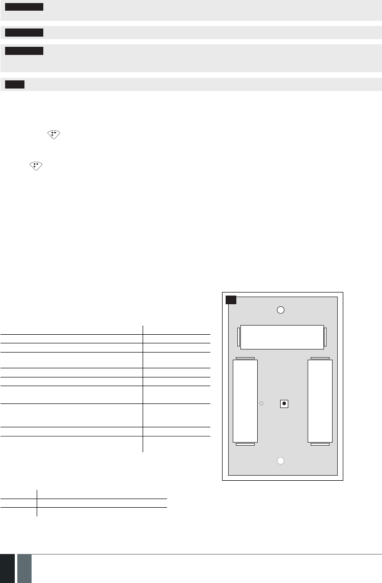
152
152 EN MANUAL ELDES ESIM364 V1.5
ATTENTION: Only CR2032 3V batteries can be used. Install only new, high quality and unexpired batteries. Do not mix the old batteries
with the new ones.
ATTENTION: At least 1 battery must be removed if the device is not in use.
ATTENTION: In order to avoid re or explosion hazards, the system must be used only with approved battery. Special care must be
taken when connecting positive and negative battery terminals. Dispose old batteries only into special collection sites. Do not charge,
disassemble, heat or incinerate old batteries.
NOTE: The battery status can be monitored in real-time using ELDES Conguration Tool software.
33.5.5. Restoring Default Parameters
1. Remove the battery from EWK1 keyfob.
2. Press and hold button.
3. Insert the battery back to EWK1.
4. Hold the button pressed until LED indicator provides several short ashes.
5. Release button.
6. Parameters restored to default.
33.6. EWS1 – Wireless Indoor Siren
Main EWS1 features:
• Audio alarm indication by built-in speaker.
EWS1 is a wireless device with built-in siren speaker and operates with ELDES wireless alarm systems. EWS1 has to be bind to the alarm sys-
tem by sending a corresponding SMS text message or using software ELDES Conguration Tool. Upon successful EWS1 binding, the system
adds one wireless zone and one wireless PGM output. The wireless zone is used to monitor the device (tamper - when the batteries are being
removed) and the wireless PGM output is used to control the speaker. In case of alarm, the siren provides a sound alarm for one minute. The
conguration of this parameter is disabled for EWS1 in order to save the battery power.
It is possible to connect up to 32 EWS1 devices to the alarm system at a time. The maximum wireless connection range is 150 meters (in open areas).
33.6.1. Technical Specications
33.6.1.1. Electrical & Mechanical Characteristics
Battery Type 1,5V Alkaline AA type
Number of Batteries 3
Battery Operation Time ~18 months*
Wireless Transmitter-Receiver Frequency 868 Mhz (EU version)
/ 915 Mhz (US version)
Range of Operating Temperatures -20...+55ºC
Dimensions 123x73x36mm
Humidity 0-90% RH @ 0... +40 °C
(non-condensing)
Wireless Communication Range Up to 30 meters in pre-
mises; up to 150 me-
ters in open areas
Compatible with Alarm Systems ELDES Wireless
Acoustic sound level ~97 dB measured at
1 m
* The operation time depends on dierent conditions and may vary.
33.6.1.2. Main Unit & LED Functionality
RESET Button for restoring default parameters
+ / - Battery slots
LED EWS1 status indication
BATTERY
RESETLED
+
-
BATTERY +
-
BATTERY
-
+
74
33.6.2. Installation

153
153EN
MANUAL ELDES ESIM364 V1.5
1. Open EWS1 enclosure.
75 76
Insert a thin at-shaped screwdriver or any tool alike into the gap lo-
cated on the back of the enclosure (see Fig. No. 75).
Push the screwdriver down to the right carefully in order to detach
the enclosure parts from each other (see Fig. No. 76).
2. Once the enclosure is opened, remove the plastic tab inserted between one of the battery terminals and battery slot contact (see Fig. No.
77).
77
3. Fix the siren on the wall using the screws (see Fig. No. 78).
BATTERY
RESETLED
+
-
BATTERY +
-
BATTERY
-
+
78
4. Close EWS1 enclosure. No tools are required for this action.
5. Bind the device to the alarm system by sending a corresponding command via SMS text message or using ELDES Conguration Tool software.
Please, refer to the software‘s HELP section or refer to 19.1. Binding, Removing and Replacing Wireless Devices for more details.
6. The system automatically informs about successful/unsuccessful binding process. If attempt to bind is unsuccessful, try to move EWS1
closer to alarm system device and bind it again.
7. EWS1 siren is ready for use.
NOTE: If you are unable to bind the wireless device please , restore the parameters of the wireless device to default and try again. See
33.6.5. Restoring Default Parameters for more details.

154
154 EN MANUAL ELDES ESIM364 V1.5
ATTENTION: The minimum wireless connection range between the wireless device and wireless antenna of ESIM364 system can be
0,5 meters.
33.6.3. EWS1 Zone, PGM Output & Tamper
Upon successful EWS1 indoor siren binding process,the system adds 1 wireless Instant zone and 1 wireless Siren PGM output. The wireless
zone is intended for EWS1 tamper control and the wireless PGM output is for siren control.
In case of tamper violation, the alarm is caused regardless of system being armed or disarmed. The wireless connection loss between EWS1
and ESIM364 system leads to alarm. The system identies this event as a tamper violation and sends alarm by SMS text message and phone
call to the user (-s) by default. The SMS text message contains the violated tamper number and a star * character indicating wireless connec-
tion loss as a tamper alarm cause.
ATTENTION: The tamper will not operate if the wireless zone is disabled.
33.6.4. Battery Replacement
1. Open EWS1 enclosure.
2. Remove all 3 old batteries from the battery slots.
3. Postition the 3 new 1,5V alkaline AA type batteries according to the appropriate battery slot positive/negative terminals indicated on the
PCB (printed-circuit-board) of EWS1
4. Insert the batteries into the battery slots.
5. Batteries replaced.
For more details, please refer to 33.6.2 Installation.
ATTENTION: Only CR2032 3V batteries can be used. Install only new, high quality and unexpired batteries. Do not mix the old batteries
with the new ones.
ATTENTION: At least 1 battery must be removed if the device is not in use.
ATTENTION: In order to avoid re or explosion hazards, the system must be used only with approved battery. Special care must be
taken when connecting positive and negative battery terminals. Dispose old batteries only into special collection sites. Do not charge,
disassemble, heat or incinerate old batteries.
NOTE: The battery status can be monitored in real-time using ELDES Conguration Tool software.
33.6.5. Restoring Default Parameters
1. Remove any battery from EWS1.
2. Press and hold the RESET button.
3. Insert the battery back to EWS1.
4. Hold the RESET button until LED indicator provides several short ashes.
5. Release the RESET button.
6. Parameters restored to default.
33.7. EWS2 – Wireless Outdoor Siren
Main EWS2 features:
• Audio alarm indication by built-in speaker;
• Visual alarm indication by built-in LED indicators;
• Range of operating temperature: -30...+55oC.
EWS2 is a wireless outdoor device with a built-in siren speaker, LED indicators and operates with ELDES wireless alarm systems. EWS2 has to
be bind to the alarm system by sending a corresponding SMS text message or using software ELDES Conguration Tool. Upon successful EWS2
binding process, the system adds one wireless zone and one wireless PGM output. In case of alarm, the siren provides a sound alarm for one
minute. The conguration of this parameter is disabled for EWS2 in order to save the battery power.
It is possible to connect up to 32 EWS2 devices to the alarm system at a time. The maximum wireless connection range is 150 meters (in open
areas).

155
155EN
MANUAL ELDES ESIM364 V1.5
33.7.1. Technical Specications
33.7.1.1. Electrical & Mechanical Characteristics
Battery Type 1,5V Alkaline AA type
Number of Batteries 4
Battery Operation Time ~18 months*
Wireless Transmitter-Receiver Frequency 868 Mhz (EU version) / 915 Mhz
(US version)
Range of Operating Temperatures -30...+55ºC
Dimensions 201 x 140 x 36 mm
Humidity 0-90% RH @ 0... +40 °C (non-con-
densing)
Wireless Communication Range Up to 30 meters in premises; up to
150 meters in open areas
Compatible with Alarm Systems ELDES Wireless
Acoustic sound level ~104 dB measured at 1 m
* The operation time depends on dierent conditions and may vary.
33.7.1.2. Main Unit, LED & Connector Functionality
RESET Button for restoring default parameters
+ / - Battery slots
LED indicators Visual alarm indication
Tamper Tamper button terminals
Bell+ Positive siren speaker terminal
Bell- Negative siren speaker terminal
RESET
TAMPER
TAMPER
+ -
BELL
BATTERY + -
+-+-
+ - BATTERY
BATTERY BATTERY
79
33.7.2. Installation
1. Open EWS2 enclosure.
80 81
Remove the small blue lid located on the front side of the enclosure
by pulling the lid up. (see Fig. No. 80).
Unscrew the front side of the enclosure (see Fig. No. 81).
2. Once the enclosure is opened, remove the plastic tab inserted between one of the battery terminal and battery slot contact (see Fig. No. 82).
82

156
156 EN MANUAL ELDES ESIM364 V1.5
3. Fix the siren on the wall using the screws (see Fig. No. 83).
BATTERY
+ -
+- +-
+ -
BATTERY
BATTERY BATTERY
83
4. Close EWS2 enclosure (see Fig. No. 81, Fig. No. 80)
5. Bind the device to the alarm system by sending a corresponding command via SMS text message or using ELDES Conguration Tool soft-
ware. Please, refer to the software‘s HELP section or refer to 19.1. Binding, Removing and Replacing Wireless Devices for more
details.
6. The system automatically informs about successful/unsuccessful binding process. If attempt to bind is unsuccessful, try to move EWS2
closer to alarm system device and bind it again.
7. EWS2 siren is ready for use.
NOTE: If you are unable to bind the wireless device please , restore the parameters of the wireless device to default and try again. See
33.7.6. Restoring Default Parameters for more details.
ATTENTION: The minimum wireless connection range between the wireless device and wireless antenna of ESIM364 system can be
0,5 meters.
33.7.3. EWS2 Zone, PGM Output & Tamper
Upon successful EWS2 outdoor siren binding process,the system adds 1 wireless Instant zone and 1 wireless Siren PGM output. The wireless
zone is intended for EWS2 tamper control and the wireless PGM output is for siren control.
In case of tamper violation, the alarm is caused regardless of system being armed or disarmed. There are 2 ways to detect tamper violation
on EWS2:
• By tamper button. EWS2 has a built-in tamper button intended for monitoring the enclosure status. Once the enclosure of EWS2
is illegally opened, the tamper button becomes unpressed. This action is followed by alarm which is sent by SMS text message and
phone call to the user (-s) by default. The SMS text message contains the violated tamper number.
• By wireless connection loss. The wireless connection loss between EWS2 and ESIM364 alarm system leads to alarm. The sys tem
identies this event as a tamper violation and sends alarm by SMS text message and phone call to the user (-s) by default. The SMS
text message contains the violated tamper number and a star * character indicating wireless connection loss as a tamper alarm cause.
ATTENTION: The tamper will not operate if the wireless zone is disabled.
33.7.4. Battery Replacement
1. Open EWS2 enclosure.
2. Remove all 4 old batteries from the battery slots.
3. Postition the 4 new 1,5V alkaline AA type batteries according to the appropriate battery slot positive/negative terminals indicated on the
PCB (printed-circuit-board) of EWS2
4. Insert the batteries into the battery slots.
5. Batteries replaced.

157
157EN
MANUAL ELDES ESIM364 V1.5
For more details, please refer to 33.7.2 Installation.
ATTENTION: Only 1,5V Alkaline AA type batteries can be used. Install only new, high quality and unexpired batteries. Do not mix the old
batteries with the new ones.
ATTENTION: At least 1 battery must be removed if the device is not in use.
ATTENTION: In order to avoid re or explosion hazards, the system must be used only with approved battery. Special care must be
taken when connecting positive and negative battery terminals. Dispose old batteries only into special collection sites. Do not charge,
disassemble, heat or incinerate old batteries.
NOTE: The system sends an SMS message to a preset User 1 as soon as the battery level runs below 5%.
NOTE: The battery status can be monitored in real-time using ELDES Conguration Tool software.
33.7.5. Restoring Default Parameters
1. Remove any battery from EWS2.
2. Press and hold the RESET button.
3. Insert the battery back to EWS2.
4. Hold the RESET button until LED indicator provides several short ashes.
5. Release the RESET button.
6. Parameters restored to default.
33.8. EW1B - Battery-Powered Wireless Zone & PGM Output Expansion Module
Main EW1B features:
• 2 zones for wired sensor connection;
• 2 PGM outputs for electrical appliance connection.
Wireless expansion module EW1B is a wireless device with 2 zones and 2 PGM outputs. This expansion module connects to ELDES wireless
alarm systems and enables wireless access for to 2 wired devices such as movement PIR sensors, magnetic door contacts etc. In addition it
allows to connect and control up to 2 appliances, i.e. lighting, heating etc. After the wiring process to EW1B it is necessary to bind EW1B to the
alarm system by sending a corresponding command via SMS text message or using software ELDES Conguration Tool. t is possible to connect
up to 32 EW1B devices to ESIM364 alarm system at a time. The maximum wireless connection range is 150 meters (in open areas).
33.8.1. Technical Specications
33.8.1.1. Electrical & Mechanical Characteristics
Battery Type 1,5V Alkaline AA type
Number of Batteries 3
Battery Operation Time ~18 months*
Number of Zones 2
Zone Connection Type Normally closed (NC)
Number of PGM Outputs 2
EW1B PGM Output Circuit 1 R
OUT
Open Collector Output.
Output is pulled to COM
when turned ON.
Maximum Commuting PGM Output Values Voltage – 30V; current 500mA
Wireless Transmitter-Receiver Frequency 868 Mhz (EU version) / 915 Mhz (US version)
Wireless Communication Range Up to 30 meters in premises; up to 150 meters in open
areas
Compatible with Alarm Systems ELDES Wireless
Range of Operating Temperatures -20...+55ºC
EW1B PCB Dimensions 38x60x12mm
EW1B Enclosure Dimensions 90x110x40mm
Humidity 0-90% RH @ 0... +40 °C (non-condensing)
Enclosure rating IP65
* The operation time depends on dierent conditions and may vary.

158
158 EN MANUAL ELDES ESIM364 V1.5
33.8.1.2. Connector & LED Functionality
COM Common terminal for zones
Z2, Z1 Security zone terminals
C2, C1 PGM output terminals
D1, D2 Pins for restoring default parameters
LED EW1B status
D1
LED
D2
C2
COM
Z1
C1
Z2
BATTERY
BATTERY
BATTERY
+
+
+
84
33.8.2. Installation
1. Push down the screwdriver and turn it counter-clockwise to un-
screw EW1B enclosure (see Fig. No. 85).
2. Detach the front side of the enclosure by pulling the front side
up (see Fig. No. 86).
85 86
3. Remove the plastic tab inserted between one of the battery
terminals and battery slot contacts (see Fig. No. 87).
4. Connect the ciruit as indicated in Fig. No. 88.
87
EW1B
Sensor
Sensor
C1 C2 Z1 Z2 COM
88
6. Close EW1B enclsoure (see Fig. No. 86, Fig. No. 85).
7. Bind the device to the alarm system by sending a corresponding command via SMS text message or using ELDES Conguration Tool software.
Please, refer to the software‘s HELP section or refer to 19.1. Binding, Removing and Replacing Wireless Devices for more details.
8. The system automatically informs about successful/unsuccessful binding process. If attempt to bind is unsuccessful, try to move EW1B
closer to alarm system device and bind it again.
9. EW1B is ready for use.

159
159EN
MANUAL ELDES ESIM364 V1.5
NOTE: If you are unable to bind the wireless device please , restore the parameters of the wireless device to default and try again. See
33.8.5. Restoring Default Parameters for more details.
ATTENTION: The minimum wireless connection range between the wireless device and wireless antenna of ESIM364 system can be 0,5
meters.
33.8.3. EW1B Zones, PGM Outputs & Tamper
Upon successful EW1B module binding process, the system adds 2 wireless Instant zones intended for wired sensor connection and 2 wire-
less PGM outputs intended for electrical appliance connection and control. The wireless connection loss between EW1B and ESIM364 alarm
system leads to system alarm regardless of system being armed or disarmed. The system identies this event as a tamper violation and sends
alarm by SMS text message and phone call to the user (-s) by default. The SMS text message contains the violated tamper number and a star *
character indicating wireless connection loss as a tamper alarm cause.
33.8.4. Battery Replacement
1. Open EW1B enclosure.
2. Remove all 3 old batteries from the battery slots.
3. Postition the 3 new 1,5V alkaline AA type batteries according to the appropriate battery slot positive/negative terminals as indicated.
4. Insert the batteries into the battery slots.
5. Batteries replaced.
For more details, please refer to 33.8.2. Installation.
ATTENTION: Only 1,5V Alkaline AA type batteries can be used. Install only new, high quality and unexpired batteries. Do not mix the old
batteries with the new ones.
ATTENTION: At least 1 battery must be removed if the device is not in use.
ATTENTION: In order to avoid re or explosion hazards, the system must be used only with approved battery. Special care must be
taken when connecting positive and negative battery terminals. Dispose old batteries only into special collection sites. Do not charge,
disassemble, heat or incinerate old batteries.
NOTE: The system sends an SMS message to a preset User 1 as soon as the battery level runs below 5%.
NOTE: The battery status can be monitored in real-time using ELDES Conguration Tool software.
33.8.5. Restoring Default Parameters
1. Remove any battery from EW1B.
2. Short circuit (connect) pins D1 and D2.
3. Insert the battery back to EW1B.
4. Wait untill LED provides several short ashes.
5. Remove short-circuit from D1 and D2 pins.
6. Parameters restored to default.
33.9. EWF1 - Wireless Smoke Detector
Main EWF1 features:
• Photoelectric sensor for slow smouldering res
• TEST button
• Non-radioactive technology for environmental friendly
• High and stable sensitivity
• Quick x mounting plate for easy installation
• LED operation indicator
• Built-in speaker for audio alarm indication
• Auto-reset when smoke clears
EWF1 is a wireless photoelctric type smoke detector intended to use with ELDES wireless alarm systems. Photoelectric smoke detectors
are generally more eective at detecting smouldering res which smoulder for hours before bursting into ame. An optical method is
used for the detection of visible smoke. When the concentration of smoke in the optical chamber exceeds a given threshold, EWF1 sounds
the alarm and sends out a signal to the ESIM364 alarm system using the wireless connection and the system triggers the alarm. By
default, when more than one EWF1 device is used, the system will automatically activate the interconnection feature (see 33.9.4. In-
terconnection). ESIM364 system support up to 32 EWF1 devices, The maximum wireless connection range is 150 meters (in open areas).
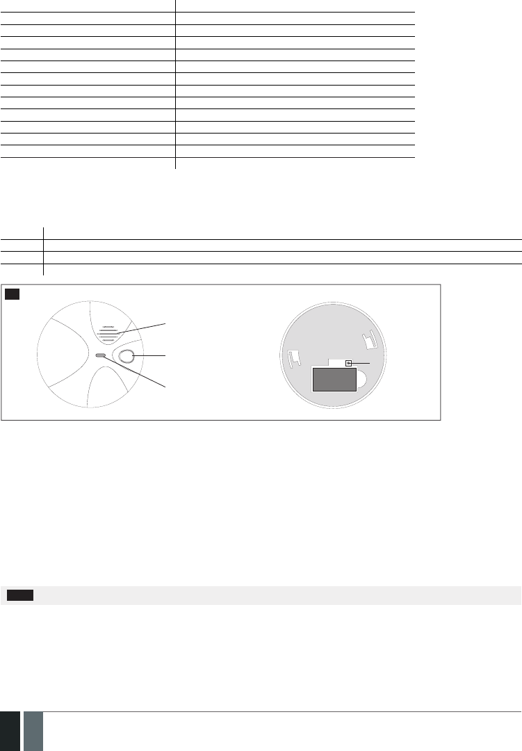
160
160 EN MANUAL ELDES ESIM364 V1.5
33.9.1. Technical Specications
33.9.1.1. Electrical & Mechanical Characteristics
Detection Type Photoelectric chamber
Alarm Sound Level 85 Decibels at 3 meters
Battery Voltage 9V
Battery Type 6F22 primary alkaline
Number of Batteries 1
Battery Operation Time ~18 months*
Wireless Transmitter-Receiver Frequency 868 Mhz (EU version) / 915 Mhz (US version)
Wireless Communication Range Up to 30 meters in premises; up to 150 meters in open areas
Range of Operating Temperatures 5oC to 45oC
Humidity 0-90% RH @ 0... +40 °C (non-condensing)
Sensitivity to Smoke 3.0-6.0 % Obs /m
Dimensions 110mm Ø
Compatible with Alarm Systems ELDES Wireless
Acoustic sound level ~98 dB measured at 1 m
* The operation time depends on dierent conditions and may vary.
33.9.1.2. Main Unit & LED Functionality
TEST Button for testing / button for testing and restoring default parameters (if RESET button not available)
LED EWF1 status indication
SIREN Built-in speaker for audio alarm indication
RESET** Button for restoring default parameters
Siren
TEST button
LED indicator
FRONT SIDE BACK SIDE
RESET button**
BATTERY
89
** Unavailaible on some EWF1 models
33.9.2. PLACEMENT
1. Install the wireless smoke detector as close to the center of the ceiling as possible. If this is not practical, mount no closer than 10
centimeters from a wall or corner. Also, if local codes allow, install wireless smoke detectors on walls, between 10 and 30 centimeters
from ceiling/wall intersections.
2. Install a minimum of two wireless smoke detectors in every house, no matter how small the house is.
3. Install a wireless smoke detector in each room that is divided by a partial wall (either coming down from the ceiling at least 20 centim-
eters, or coming up from the oor).
4. Install a wireless smoke detector in lived-in attics or attics which ho use electrical equipment like furnaces, air conditioners, or heaters.
NOTE: For best protection we recommend that you install a wireless smoke detector in every room.

161
161EN
MANUAL ELDES ESIM364 V1.5
Recommended EWF1 placement locations
Ceiling
Wall
HORIZONTAL DISTANCE
ANYWHERE
IN THIS AREA
NEVER
HERE
Acceptable
here
0,9 m (3 ft) 0,9 m (3 ft) Top of detector
acceptable here
(0,1 m)
(0,1 m)
Max.
(0,3 m)
Max.
90
NOTE: Measurements shown are to the closest edge of the detector.
Typical Single-Story House
Install a wireless smoke detector on the ceiling or wall inside each bedroom and in the hallway outside each separate sleeping area. If a
bedroom area hallway is more than 9 meters long, install a wireless smoke detector at each end.
If there is a basement: Install a wireless smoke detector on the basement ceiling at the bottom of the stairwell.
Bedroom
Bedroom
Family Room
Living Room
Kitchen
Dining Room Bedroom
91
LEGEND:
Minimum required smoke
detector locations.
Recommended additional
smoke detector locations

162
162 EN MANUAL ELDES ESIM364 V1.5
Typical Multi-Story or Split-Level House
Install a wireless smoke detector on the ceiling or wall inside each
bedroom and in the hallway outside each separate sleeping area. If
a bedroom area hallway is more than 9 meter long, install a wire-
less smoke detector at each end. Please install a wireless smoke
detector on the top of a rst-to-second oor stairwell.
LEGEND:
Minimum required smoke detector locations.
Recommended additional smoke detector locations
Bedroom Bedroom
Basement
Living
Room
Dining
Room
92
Incorrect EWF1 Placement
DO NOT place EWF1 in the following locations:
• Near appliances or areas where normal combustion regularly occurs (kitchens, near furnaces, hot water heaters). Use specialized
wireless smoke detector with unwanted alarm control for this areas.
• In areas with high humidity, like bathrooms or areas near dishwashers or washing machines. Install at least 3 meters away from these
areas.
• Near air returns or heating and cooling supply vents. Install at least 1 meter away from these areas. The air could blow smoke away
from the detector, interrupting its alarm.
• In rooms where temperatures may fall below 5oC or rise above 45oC.
• In extremely dusty, dirty, or insect-infested areas where loose particles interfere with wireless smoke detector operation.
ATTENTION: Incorrect placement will result in a decrease of operational eectiveness.
33.9.3. Installation
1. Detach the mounting plate by turning it counter-clockwise from
the back of EWF1 (see Fig. No. 93).
2. Secure the mounting plate to ceiling or wall with mounting
screws.(see Fig. No. 93).
3. Lift to open the battery pocket door (see Fig. No. 93).
4. Insert the battery into the battery pocket considering the po-
larity terminals indicated on the enclosure of EWF1. Ensure the
battery is securely connected. Red LED may ash briey when
the battery is being installed.
5. Close the battery pocket door by snapping it into place.
6. Position the smoke detector to the mounting plate by turning
it clockwise to lock into place. Note that the device will not lock
into the mounting plate without the battery being present in
the battery pocket.
7. 7. Push the TEST button to verify if the wirless smoke detector is
operational. See 33.9.5.1. Testing EWF1.
8. Bind the device to the alarm system by sending a corresponding
command via SMS text message or using ELDES Conguration
Tool software. Please, refer to the software‘s HELP section or
refer to 19.1. Binding, Removing and Replacing Wireless
Devices for more details.
6. The system automatically informs about successful/unsuccess-
ful binding process. If attempt to bind is unsuccessful, try to
move EWF1 closer to alarm system device and bind it again.
10. EWF1 wireless smoke detector is ready for use.
Mounting slot
Screws
Battery pocket door
Mounting plate
93
NOTE: If you are unable to bind the wireless device, please restore the parameters of the wireless device to default and try again. See chap-
ter 33.9.6. Restoring Default Parameters for more details.

163
163EN
MANUAL ELDES ESIM364 V1.5
33.9.4. Interconnection
The interconnection feature automatically links all wireless smoke detectors resulting in causing an instant alarm in the system along
with the rest of EWF1 wireless smoke detectors. For more details on interconnection feature and how to manage it, please refer to 20.4.
EWF1 Interconnection.
33.9.5. Maintenance
33.9.5.1. Testing EWF1
• The TEST button veries if EWF1 is operational. Firmly push the TEST button and the wireless smoke detector will sound a loud beep.
The alarm will stop sounding after releasing the TEST button. When testing EWF1 using ELDES Conguration Tool software, the
detector will provide short beeps.
• Stand at arm’s length from the wireless smoke detector when testing.
• Test wireless smoke detectors weekly and upon returning from vacation or when no one has been in the household for several days.
• Test each wireless smoke detector to be sure it is installed correctly and operating properly.
• DO NOT use an open ame to test this wireless smoke detector. You may ignite and dam age the wireless smoke detector or your
home.
• If the wireless smoke detector does not sound, please check the battery and signal level using ELDES Conguration Tool software.
ATTENTION: Test all wireless smoke detectors weekly to ensure proper operation.
33.9.5.2. Battery Replacement
1. Turn EWF1 counter-clockwise to detach it from the mounting
plate.
2. Gently pull down the wireless smoke detector.
3. Remove the old battery from the battery pocket.
4. Postition the new 9V battery according to the appropriate
battery slot positive/negative terminals indicated on the
enclosure of EWF1. Ensure the plastic battery holder is fully
depressed when the battery has been tted.
5. Using the TEST button, test the wireless smoke detector to
verify if it is operational. See 33.9.5.1. Testing EWF1.
6. Re-attach the wireless smoke detector to the mounting plate
by turning the wireless smoke detector clockwise until it snaps
into place.
9V battery
94
ATTENTION: Only 9V 6F22 primary alkaline type battery can be used. Install only new, high quality and unexpired batteries.
ATTENTION: The battery must be removed if the device is not in use.
ATTENTION: In order to avoid re or explosion hazards, the system must be used only with approved battery. Special care must be taken
when connecting positive and negative battery terminals. Dispose old batteries only into special collection sites. Do not charge, disassemble,
heat or incinerate old batteries.
NOTE: The battery status can be monitored in real-time using ELDES Conguration Tool software.
NOTE: The system sends an SMS message to the preset user phone number as soon as the battery level runs below 5%.
33.9.6. Restoring Default Parameters
1. Remove the battery from EWF1.
2. Press and hold the RESET button.
3. Insert the battery back to EWF1.

164
164 EN MANUAL ELDES ESIM364 V1.5
4. Hold the RESET button until you hear a short beep.
5. Release the RESET button.
On some EWF1 models the RESET button is not available. On such EWF1 devices the reset process is as follows:
1. Remove the battery from EWF1.
2. Wait for 1 minute or more.
3. Press and hold the TEST button.
4. Insert the battery back to EWF1.
5. Hold the TEST button for 10 seconds or more.
6. Release the TEST button.
ATTENTION: EWF1 built-in speaker will sound while pressing and holding the TEST button. Please, ignore the sound.
33.9.7. Cleaning
Clean the wireless smoke detector at least once a month to remove dust, dirt, or debris. Using the soft brush or wand attachment of a
vacuum cleaner, vacuum all sides and cover of wireless smoke detector. Be sure all the vents are free of debris.
If necessary, use a damp cloth to clean wireless smoke detector cover.
NOTE: Do not attempt to remove the cover to clean inside the wireless smoke detector. This will void your warranty.
33.10. EWK2 - Wireless Keyfob
Main EWK2 features:
• Alarm system arming & disarming;
• Panic button;
• PGM output control;
• Sound indication by built-in mini buzzer;
• Visual indication by built-in LED indicator.
EWK2 is a wireless device intended to remotely arm and disarm ELDES alarm system, cause system alarm or to control any electric ap-
pliance connected to the alarm system’s PGM output. In order to start using wireless keyfob EWK2, it has to be bound to ELDES wireless
alarm system using ELDES Conguration Tool software or sending a corresponding SMS command. EWK2 keyfob features four congurable
buttons intended to operate according to individual needs. After the button is pressed, EWK2 internal buzzer’s sound signal and red LED
indicator conrms a transferred command to ELDES alarm system via wireless connection. The status of the sent command can be checked
by attempting to receive the feedback signal from the alarm system. This can be performed by pressing down the same button again and
holding it for 3 seconds. 3 short sound signals and LED indicator ashes indicate a successfully carried out command, while 1 long beep and
LED indicator ash stands for failed command and feedback signal failure. By default, one pair of buttons is already congured to arm and
disarm the alarm system. It is possible to connect up to 5 EWK2 devices to ELDES alarm system at a time. The maximum wireless connection
range is 150 meters (in open areas).
33.10.1. Technical Specications
Optional
functionality Optional
functionality
Disarm the
system
Arm the
system
LED
indicator
NOTE: Figure reects the default EWK2 button conguration. All keyfob buttons are congurable according to individual needs.
95

165
165EN
MANUAL ELDES ESIM364 V1.5
33.10.1.1. Electrical & Mechanical Characteristics
Battery Type CR2032 Lithium
Battery Voltage; Capacity 3V; 240 mAh
Quantity of Batteries 1
Battery Operation Time ~18 months*
Wireless Transmitter-Receiver Frequency 868 Mhz (EU version) / 915 Mhz (US version)
Range of Operating Temperatures -20...+55ºC
Humidity 0-90% RH @ 0... +40 °C (non-condensing)
Dimensions 53 x 37 x 10 mm
Wireless Communication Range Up to 30 meters in premises; up to 150 meters in open
areas
Compatible with Alarm Systems ELDES Wireless
* The operation time depends on dierent conditions and may vary.
33.10.2. Installation
1. Open the EWK2 enclosure. Detach the front side of the enclosure by pulling the front side down
96
2. Once the enclosure is opened, remove the PCB from the EWK2 enclosure and ip the PCB so that the back side would be facing up.
97
98
3. Insert the CR2032 type battery provided in the EWK2 package. Before inserting the battery, ensure that it is positioned plus-marked
side up.
BATTERY
CR2032
+
99

166
166 EN MANUAL ELDES ESIM364 V1.5
4. Insert the PCB back to the enclosure and close it.
5. Bind the device to the alarm system by sending a corresponding command via SMS text message or using ELDES Conguration Tool
soft ware. Please, refer to the software‘s HELP section or refer to 19.1. Binding, Removing and Replacing Wireless Devices for
more details.
6. While binding the device to the alarm system, press any EWK2 button several times.
7. EWK2 is ready for use.
NOTE: If you are unable to bind the wireless device, please, restore the parameters of the wireless device to default and try again. See
chapter 33.10.5. Restoring Default Parameters for more details.
33.10.3. EWK2 Zones (Panic Button)
EWK2 keyfob supports a Panic Button feature allowing to cause alarm at any time when the specied button is pressed. This feature can
be congured using ELDES Conguration Tool by creating a virtual zone of Panic/Silent or 24-Hour type and assigning it to Virtual Alarm
option. The Panic Button feature can be set up on any button of EWK2.
33.10.4. Battery Replacement
1. Open EWK2 enclosure.
2. Remove the old battery from the battery slot.
3. Postition the new battery according to the appropriate battery slot positive terminal indicated.
4. Insert the battery into the battery slot.
5. Battery replaced.
See 33.10.2. Installation for more details.
ATTENTION: Only CR2032 3V battery can be used. Install only new, high quality and unexpired batteries.
ATTENTION: The battery must be removed if the device is not in use.
ATTENTION: In order to avoid re or explosion hazards, the system must be used only with approved battery. Special care must be
taken when connecting positive and negative battery terminals. Dispose old batteries only into special collection sites. Do not charge,
disassemble, heat or incinerate old batteries.
NOTE: The system sends an SMS message to a preset User 1 as soon as the battery level runs below 5%.
NOTE: The battery status can be monitored in real-time using ELDES Conguration Tool software.
33.10.5. Restoring Default Parameters
1. Press and hold and buttons simultaneously.
2. Hold the buttons pressed until LED indicator and the buzzer provide several short ashes and beeps simultaneously.
3. Release the buttons.
4. Parameters restored to default.
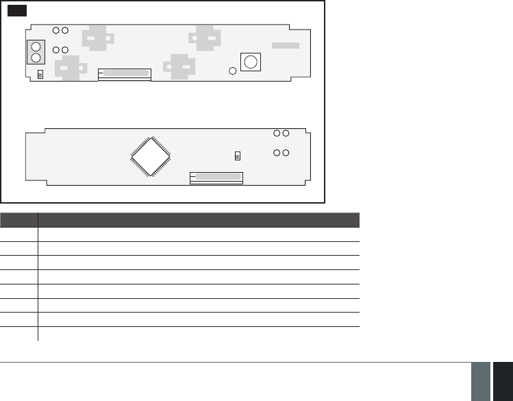
167
167EN
MANUAL ELDES ESIM364 V1.5
33.11. EWD2 - Wireless Door Contact/Shock Sensor
Main EWD2 features:
• Built-in shock sensor
• 2 wireless zones
• Available zone modes: magnetic door contact, shock sensor, water sensor, digital sensor
• 2 built-in tamper switches: on the front and on the back of the PCB
EWD2 is a wireless device intended to secure doors, windows or any other opening/clsoing mechanisms. In addition, the device comes
equiped with a built-in shock sensor for vibration detection, an on-board zone terminal designed for external digital sensor or water sensor
connection and 2 built-in tamper switches for EWD2 sabotage detection. In order to start using EWD2, it has to be bound to ELDES alarm
system using ELDES Conguration Tool software or by sending a corresponding SMS text message to ELDES alarm system.
It is possible to connect up to 32 WD2 devices to ESIM364 alarm system. The maximum wireless connection range is 150 meters (in open
areas).
33.11.1. Technical Specications
33.11.1.1. Electrical and Mechanical Characteristics
Batteries ..................................................................................................1,5V Alkaline AAAA type, LR8 (IEC standard) / 25A (ANSI/NEDA standard)
Number of batteries ..............................................................................2
Battery operation time .........................................................................~18 months*
Wireless transmitter-receiver frequency .........................................868 Mhz (EU version) / 915 Mhz (US version)
Wireless communication range ..........................................................Up to 30 meters in premises; up to 150 meters in open areas
Range of operating temperatures .....................................................-20...+55ºC
Humidity .................................................................................................0-90% RH @ 0... +40 °C (non-condensing)
EWD2 dimensions .................................................................................101 x 22 x 20 mm
Magnet dimensions ...............................................................................47 x 17 x 10 mm
Compatible with alarm systems ..........................................................ELDES wireless
* The operation time depends on dierent conditions and may vary.
33.11.1.2. Main Unit and LED Functionality
Z
COM
+
+
-
-
TAMP1 DETECT
DETECT
FRONT SIDE
BACK SIDE
LED
RESET
TAMP2
100
Unit Description
Z Zone terminal
COM Common terminal
TAMP1 Tamper switch
+ / - Battery slots
DETECT Magnet detector
LED Light-emitting diode for indication of parameter restoring to default
RESET Button for restoring default parameters
TAMP2 Tamper switch

168
168 EN MANUAL ELDES ESIM364 V1.5
33.11.2. Installation
1. Remove the cover of EWD2 enclosure.
Press and hold
Insert a screwdriver or
any other tool and push it down
101 102
2. Remove the PCB (printed-circuit-board) from the enclosure.
a) Press and hold
b) Pull up the edge
of the PCB
103
3. Screw in the enclsoure to the door or window jamb.
MOUNTING POINT A
MOUNTING POINT B
Ensure to screw in properly for supervision
of the back side by tamper switch
104
4. Wire up the external digital sensor (if any) or water sensor (if any) to Z and COM terminals, otherwise do not perform any wiring.
5. Insert the PCB back into the enclosure
107
109
108

169
169EN
MANUAL ELDES ESIM364 V1.5
6. Remove the cover of the magnet enclosure.
b) Pull up here a) Insert a screwdriver or any
other tool and push it down
110
7. Screw in the magnet to the door or window frame and ensure that the magnet is xed at the same height as the EWD2 magnet detector.
111
20 mm max
+
+
-
-LED
RESET
112
8. Cover the magnet. No tools are required for this action.
9. Remove the plastic tab inserted between one of the battery terminals and battery slots of EWD2.
113
10. Close EWD2 enclosure using the cover. No tools are required for this action.
11. Bind the device to the alarm system by sending a corresponding command via SMS text message or using ELDES Conguration Tool
software. Please, refer to the software‘s HELP section or refer to 19.1. Binding, Removing and Replacing Wireless Devices for
more details.
12. The system automatically informs about successful/unsuccessful binding process. If attempt to bind is unsuccessful, try to move EWD2
closer to alarm system device and bind it again.
13. EWD2 is ready for use.
ATTENTION: Ensure that EWD2 device is properly xed to the wall and the Mounting Point B portrayed in Fig. No. 99 is properly screwed in.
Otherwise, the tamper switch will NOT supervise the back side of EWD2 enclosure (see also 33.11.3. EWD2 Zones and Tampers).
NOTE: If you are unable to bind the wireless device, please, restore the parameters of the wireless device to default and try again. See
33.11.5. Restoring Default Parameters for more details.
33.11.3. EWD2 Zones and Tampers
Upon successful EWD2 magnetic door contact binding process, the system adds 2 wireless Instant zones. The wireless zones can be set up
to operate under one of the following modes each:
• Zone 1:
• Magnetic door contact – Designed for causing an alarm (by default) if doors/windows are opened when the system is armed.
• External sensor – Designed for causing an alarm (by default) if the wired digital sensor, connected to Z and COM terminals, is
triggered when the system is armed. This mode does NOT operate with Water sensor mode on Zone 2 simultaneously.

170
170 EN MANUAL ELDES ESIM364 V1.5
• Zone 2:
• Shock sensor – Designed for causing an alarm (by default) if the built-in shock sensor is triggered.
• Water sensor – Designed for causing an alarm (by default) if a water sensor, connected to Z and COM terminals, is triggered. This
mode does NOT operate with External sensor mode on Zone 1 simultaneously.
Possible zone mode combinations:
• Zone 1: Magnetic door contact + Zone 2: Shock sensor
• Zone 1: Magnetic door contact + Zone 2: Water sensor
• Zone 1: External Sensor + Zone 2: Shock sensor
• Zone 1: Magnetic door contact + Zone2: N/A
• Zone 1: External Sensor + Zone2: N/A
• Zone 1: N/A + Zone 2: Shock sensor
• Zone 1: N/A + Zone 2: Water sensor
In case of tamper violation, the alarm is caused regardless of system being armed or disarmed. There are 2 ways to detect tamper violation
on EWD2:
• By tamper switch. EWD2 comes equipped with 2 built-in tamper switches intended for enclosure supervision:
• one located on the front side of the PCB supervising the front cover in case it is illegally opened (see Fig. No. 100).
• the other one located on back of the PCB supervising the back side of the enclosure in case the EWD2 is illegally detached from the
wall (see Fig. No. 100).
Once the enclosure of EWD2 is tampered, the tamper switch will become triggered. This action will be followed by alarm, resulting in
sending an SMS text message and/or phone call to the user. The SMS text message contains the violated tamper number.
• By wireless connection loss. The wireless connection loss between EWD2 and ESIM364 system leads to alarm. The system
identies this event as a tamper violation and sends alarm by SMS text message and phone call to the user (-s) by default. The SMS
text message contains the violated tamper number and a star * character indicating wireless connection loss as a tamper alarm cause.
ATTENTION: The tamper will not operate if both wireless zones are disabled.
For more details on EWD2 zone and tamper conguration, please refer to ELDES Conguration Tool software’s HELP section.
33.11.4. Battery Replacement
1. Open EWD2 enclosure.
2. Remove both old batteries from the battery slots.
3. Insert the 2 new 1,5V Alkaline AAAA type batteries according to the appropriate battery slot positive/negative terminals indicated on
the PCB of EWD2.
4. Batteries replaced.
See 33.11.2. Installation for more details.
ATTENTION: Only 1,5V Alkaline AAAA type batteries can be used. Install only new, high quality and unexpired batteries. Do not mix the old
batteries with the new ones.
ATTENTION: At least 1 battery must be removed if the device is not in use.
ATTENTION: In order to avoid re or explosion hazards, the system must be used only with approved battery. Special care must be taken
when connecting positive and negative battery terminals. Dispose old batteries only into special collection sites. Do not charge, disassemble,
heat or incinerate old batteries.
ATTENTION: The system sends an SMS message to a preset user phone number as soon as the battery level runs below 5%.
ATTENTION: The battery status can be monitored in real-time using ELDES Conguration Tool software.
33.11.5. Restoring Default Parameters
1. Remove any battery from EWD2.
2. Press and hold the RESET button.
3. Insert the battery back to EWD2.
4. Hold the RESET button until LED indicator provides several short ashes.
5. Release the RESET button.
6. Parameters restored to default.

171
171EN
MANUAL ELDES ESIM364 V1.5
34. REMOTE SYSTEM RESTART
In some critical situations, a system restart may be required. To remotely carry out system restart, please refer to the following congu-
ration method.
Restart the system SMS
SMS text message content:
ssss_RESET
Value: ssss – 4-digit SMS password.
Example: 1111_RESET
35. EN 50131-1 GRADE 3
EN50131-1
GRADE 3
ESIM364 system complies with EN 50131-1 Grade 3 security standard requirements and comes equipped with the following
features:
• 6-digit SMS, administrator and user passwords.
• Prompt for SMS and administrator passwords when conguring the system using ELDES Conguration Tool software.
• Prompt for user and administrator passwords when conguring the system by EKB2, EKB3, EKB3W keypad.
• System arming is blocked if any system fault exists. The user wil not be able to arm the system until all existing system
faults are solved.
By default, the EN 50131-1 Grade 3 features are disabled. To enable/disable them, pelase refer to the following conguration methods:
Set 6-digit format for SMS,
administrator and user passwords
Cong
Tool
This operation may be carried out from the PC using the
ELDES Conguration Tool software.
Set 4-digit format for SMS,
administrator and user passwords
Cong
Tool
This operation may be carried out from the PC using the
ELDES Conguration Tool software.
Prompt for SMS and administrator passwords when
conguring the system using ELDES Conguration
Tool software.
Cong
Tool
This operation may be carried out from the PC using the
ELDES Conguration Tool software.
Prompt for administrator password when
conguring the system using ELDES Conguration
Tool software.
Cong
Tool
This operation may be carried out from the PC using the
ELDES Conguration Tool software.
Prompt for user and administrator passwords
when conguring the system by EKB2, EKB3, EKB3W
keypad.
Cong
Tool
This operation may be carried out from the PC using the
ELDES Conguration Tool software.
Prompt for administrator password when
conguring the system by EKB2, EKB3, EKB3W
keypad.
Cong
Tool
This operation may be carried out from the PC using the
ELDES Conguration Tool software.
Deny system arming if any system fault exists Cong
Tool
This operation may be carried out from the PC using the
ELDES Conguration Tool software.
Permit system arming if any system fault (except -
tamper violation) exists.
Cong
Tool
This operation may be carried out from the PC using the
ELDES Conguration Tool software.

172
172 EN MANUAL ELDES ESIM364 V1.5
36. SMART SECURITY
The system comes equipped with a Smart Security feature providing a user-friendly graphical interface intended for system status moni-
toring and control. The graphical interface can be accessed via web browser or a smart-phone application developed for Android and iOS-
based (iPhone, iPad) devices. Smart Security feature easily allows to do the following:
• Arm/disarm the system.
• Control PGM outputs.
• View system faults and alarms.
• Monitor GSM signal strength, back-up battery level and temperature.
Manage Smart
Security parameters Cong
Tool This operation may be carried out from the PC using the ELDES Conguration Tool software.
1. Before running Smart Security on ESIM364, ensure that::
• SIM card is inserted into SIM CARD1 slot of ESIM364 device (see 2.2. Main Unit, LED & Connector Functionality).
• Mobile internet service (GPRS) is enabled on the SIM card.
• Power supply is connected to ESIM364.
• Default SMS password is changed to a new 4-digit password (see 6. PASSWORDS).
• At least User 1 phone number is set up (see 8. USER PHONE NUMBERS).
• APN, user name and password are set up (see 30.2.1. GPRS Network).
2. Creating a Smart Security account
• Type in the following address in your web browser: http://se-
curity.eldes.lt
• Press Register
• In the next window ll in username, password, email address,
your personal details, verication code and press Register
button.
• Now open your email inbox and look for a new email message
received from ELDES. The email message will contain an ac-
count activation link. Please, click on the link to conrm your
account registration.
115
3. Adding the device to Smart Security account
116
• Return to http://security.eldes.lt and enter the login details.
• After successful login process you will be requested to ll in your device
details in Create Device window. In this window, please, ll in the following de-
tails:
• Name – name of your device displayed in the main screen view of
SMART SECURITY.
• Smart Security ID – a unique multi-character security code provided
with every ESIM364 unit.

173
173EN
MANUAL ELDES ESIM364 V1.5
Request Smart
Security ID SMS
SMS text message content:
ssss_SMART_ID
Value: ssss - 4-digit SMS password.
Example: 1111_SMART_ID
Cong
Tool This operation may be carried out from the PC using the ELDES Conguration Tool software.
• Device Model –select esim364 from the list.
• After lling in the device details, press Create button.
4. Controlling the System Unit via Smart Security
• After adding the device to the account time you will be brought to the next window Devices. In addition, a 6-month trial License Key
will be granted for your each device added for the rst time to your account. In this window you can view the following information on
your ESIM364 device:
• Online/Oine – device connection status.
• „Test Device“ – custom device name provided
by you.
• ID – internal sequence number of the server.
• Imei – uniqe hardcoded GSM modem number of
your ESIM364 device.
• License Key – a special key number provided
after its‘ purchase. This key allows to continue
using SMART SECURITY.
• Edit button – press to view and edit your device
details
• Delete button – press to remove your device
from SMART SECURITY account.
117
• Press Control button to start controlling your security system and electrical appliances. In the next window you can arm/disarm the
alarm system, view battery, network, temperature status, alarm reports and control electrical appliances.
118

174
174 EN MANUAL ELDES ESIM364 V1.5
5. Obtaining a new License Key
• When the period of your 6-month trial License Key is over, you
will have to purchase a new key via PayPal. Press PayPal Ex-
tend License located in the Devices in Use section of Devices
window.
• In the next window follow the instructions of the PayPal sys-
tem to complete the purchasing procedure.
• After the purchase is complete, the License Key validity ex-
tends automatically for a specied device.
119

175
175EN
MANUAL ELDES ESIM364 V1.5
37. TECHNICAL SUPPORT
37.1. Troubleshooting
Indication Possible reason
Indicator STAT is o · No main power supply
· Wiring done improperly
· Blown fuse
Indicator NETW is o or ashing · Missing SIM card
· PIN code is enabled
· SIM card is inactive
· Disconnected antenna
· GSM network signal too weak
· Problems with GSM provider
· Microcontroller is not started due to electrical mains noise or static discharge
System does not send any SMS text messages
and/or does not ring
· SIM card credit balance depleted
· Incorrect SMS centre phone number
· No GSM network signal
· User number is not added (or control from anu phone number is disabled)
· SIM card changed before disconnecting main power supply or backup battery
Received SMS text message “Wrong syntax” · Incorrect SMS text message structure
· Extra space symbol could be left in SMS text message
Missing temperature indication in Info SMS text
message/EKB2 keypad
· Temperature sensor not connected
· Temperature sensor broken
· Connection wires too long
24H and/or Fire zones do not work · Specied zone must be enabled by SMS, ELDES Conguration Tool, EKB2, EKB3
or EKB3W
No sound during remote listening · Microphone not connected
· Improper microphone connection
For product warranty repair service please , contact your local retail store where this product was purchased.
If your problem could not be xed by the self-guide above, please contact your local distributor. More up to date informa-
tion about your device and other products can be found at the manufacturer’s website www.eldes.lt
37.2. Restoring Default Parameters
1. Disconnect the power supply and backup battery.
2. Short circuit (connect) DEF pins.
3. Power up the device for 7 seconds.
4. Power down the device.
5. Remove short circuit from DEF pins.
6. Parameters restored to default.
37.3. Updating the Firmware via USB Cable Locally
1. Disconnect the power supply and backup battery.
2. Short circuit (connect) DEF pins.
3. Connect the device via USB cable to the PC.
4. Power up the device.
5. The new window must pop-up where you will nd the .bin le. Otherwise open My Computer and look for Boot Disk drive.
6. Delete the .bin le found in the drive.
7. Copy the new rmware .bin le to the very same window.
8. Power down the device.
9. Unplug USB cable.
10. Remove short circuit from DEF pins.
11. Power up the device.
12. Firmware updated.
NOTE: It is strongly recommended to restore default parameters after the rmware update.

176
176 EN MANUAL ELDES ESIM364 V1.5
37.4. Updating Firmware via GPRS Connection Remotely
ATTENTION: The system will NOT send any data to monitoring station while updating the rmware remotely via GPRS network. Howev-
er, during the rmware update process, the data messages are queued up and transmitted to the monitoring station after the rmware
upgrade process is over.
Before updating the rmware remotely via GPRS connection, make sure that:
• SIM card is inserted into SIM CARD1 slot of ESIM364 device (see 2.2. Main Unit, LED & Connector Functionality).
• Mobile internet service (GPRS) is enabled on the SIM card.
• Power supply is connected to ESIM364.
• Default SMS password is changed to a new 4-digit password (see 6. PASSWORDS).
• At least User 1 phone number is set up (see 8. USER PHONE NUMBERS).
• APN, user name and password are set up (see 30.2.1. GPRS Network).
Initiate FOTA
ESIM364 alarm system supports FOTA (rmware-over-the-air) feature. This allows to upgrade the rm-
ware remotely via GPRS connection. Once the upgrade process is initiated, the system connects to the
specied FTP server address where the rmware le is hosted and begins downloading and re-ashing
the rmware. The rmware le must be located in a folder titled Firmware. In order to initiate the upgra-
de process please , send the following SMS message.
SMS
SMS text message content:
XXXX_FOTA:ftp-server-ip,port,rmware-le-name.bin,user-name,password
Value: ssss - 4-digit SMS password; ftp-server-io - public IP address of FTP server where
EPIR rmware le is stored; port - port number of FTP server (usually - 21); rmware-le-
name.bin - name of the rmware le, allowed max. length - up to 31 character; user-name
- user name of FTP server login, allowed max. length - up to 31 character; password -
password of FTP server login, allowed max. length - up to 31 character.
Example: 1111_FOTA:84.15.143.111,21,ESIM364fw bin,eldesuser,eldespassword
ATTENTION: Comma character is NOT allowed to use in user name and rmware le name.
ATTENTION: “ELDES UAB” does not run a FTP server and does not host the rmware les online. Please, contact your local distributor to
request the latest rmware le: support@eldes.lt
NOTE: It is strongly recommended to restore default parameters after the rmware update.
37.5. Frequently Asked Questions
Question Answer
1. Can ESIM364 operate as standalone device without SIM
card inserted?
Yes, ESIM364 device can fully operate without any SIM card inserted. In this case
you will not be able to congure and control the device by SMS and calls nor to
receive any SMS reports and calls.
2. I am unable to arm the alarm system when one of the
zones (some zones) is violated, although I was able
to perform disarming. Is there a way to arm the alarm
system while the zone is violated?
Due to security reasons it is recommended to restore the violated zone (-s)
before arming the alarm system. However, you can enable a Force attribute
or use the Bypass feature in order to arm the alarm system despite the vio-
lated zone (-s) being present. Please, refer to 14.5. Zone Type Denitions
and 14.7. Bypassing and Activating Zones.
3. I have activated ATZ mode in ELDES Conguration Tool
software, but I am unable to set the connection Type 5.
Whenever I select Type 5 and press the “Write Settings”
button it switches back to Type 4. What’s wrong?
It appears that your ELDES Conguration Tool software is outdated. Please,
download the latest ELDES Conguration Tool software version by visiting
www.eldes.lt/en/download.
4. When ESIM364 fully powers down my conguration
becomes lost and I have to re-congure the device
again. What’s wrong?
This might have happened due to the jumper left on DEF pins or it is a hard-
ware failure. Please, remove the jumper if it is present on DEF pins or contact
your supplier for warranty service.
5. I have a smoke detector connected to ESIM364 system.
How do I reset the smoke detector when the “Fire” zone
is violated?
If the smoke detector is connected to one of the ESIM364 PGM outputs
you can reset it by turning the PGM output OFF and then back ON. This
can be performed by SMS, EKB2 keypad, EKB3 keypad, EKB3W keypad and
ELDES Conguration Tool software. Please, refer to 18.4. Turning PGM
Outputs ON and OFF.
6. What happens if I switch backup battery pole terminals
places?
Switching backup battery pole terminals places is forbidden. Otherwise this
will lead to blown fuse and ESIM364 alarm system will have to be repaired.
7. How do I disable SMS reports and calls in case of tamper
violation when alarm system is disarmed?
The SMS reports on tamper violation can be disabled by EKB2, EKB3, EKB3W
keypads or ELDES Conguration Tool software. For mor details, please refer
to 16. TAMPERS or to the software’s HELP section. However, due to security
reasons it is not recommended to disable this feature.

177
177EN
MANUAL ELDES ESIM364 V1.5
Question Answer
8. Is any additional conguration necessary when con-
necting EPGM1 module after wiring is done accroding to
EPGM1 user manual?
No additional conguration is required in order to make EPGM1 module
operational.
9. Does the number of EPGM1 zones duplicate when ATZ
mode is activated in the system?
No, the number of EPGM1 zones does not duplicate in ATZ mode as
EPGM1 module does not support ATZ mode. Only ESIM364 zones
duplicate in ATZ mode.
10. I connect the wired siren to ESIM364 and I hear a silent
sound alarm even when the alarm system is disarmed.
In case of alarm system alarm the siren provides a loud
sound alarm as it should. Why?
Please, connect the resistor of 3,3 k nominal to the BELL- / BELL+ contacts
This should solve the problem.
11. I am using Windows operating system. The windows
of ELDES Conguration Tool are not fully displayed and
some parts are like cut-o. What’s wrong?
Please, update ELDES Conguration Tool software by visiting www.eldes.lt/
en/download and downloading the latest version.
12. The buzzer remains active when I disarm the alarm
system using the keypad. Why?
The buzzer is intended for iButton indication only and it is not related to
disarming process by keypad.
13. One of wireless devices connected to ESIM364 system
sends a tamper alarm from time to time, although no
tamper was violated. Why?
This happens due to wireless connection loss. There might be several reasons:
1. ELDES wireless device is installed too close or too far from ESIM364
system.
2. Interference of other electronic equipment.
3. Physical interference (building walls, oors etc.)
4. Metal material interference.
14. I have connected a wired magnetic door sensor, but
I receive tamper alarm instead of zone alarm. What’s
wrong?
This happens due to incorrect resistor connection. Please, refer to corre-
sponding connection circuit according to the selected zone connection type
(Type 1 – 5). See 2.3.2 Zone Connection Types for more details.
15. I disconnected the backup battery, but did not receive
any SMS report on this event. How do I enable SMS
report on backup battery disconnection?
By default, this notication is enabled. The system checks the backup
battery resistance once a day and sends an SMS report to User 1 on backup
battery replacement if more than 2 resistance is detected. For more details,
please refer to 21. BACKUP BATTERY, MAINS POWER SUPPLY STATUS
MONITORING AND MEMORY.
16. When I check system SIM card credit balance I see a lot
of SMS delivery conrmation reports. How do I disable
SMS delivery conrmation ESIM364 system?
Every time an SMS text message is sent to the user, the system must “know”
that the message was successfully delivered. The only way to partly disable the
SMS delivery report (for alarm notications only) is to enable alarm SMS notica-
tions to all users. This is useful when having only User1 phone number set up, as
in case of alarm the system sends the alarm SMS text message to all preset users
simultaneously, but does not require any SMS delivery report.
17. I have set zone names and/or PGM output names
containing some Cyrillic and/or non-English characters.
The zone names and PGM output names do not fully t
in the SMS message. What‘s wrong?
According to GSM standards 1 SMS text message may consist of up to 160
Latin alphabet/English characters maximum. If the message contains at
least one non-latin/non-English character, the length of SMS message be-
comes at least half shorter, since those characters occupy more size of the
SMS text message than the Latin ones. It is recommended not to use any
non-Latin/ non-English characters in zone names and PGM output names.
18. The conguration of added wireless keyfob EWK1 to
ESIM364 system is not visible in ELDES Conguration
Tool. What‘s wrong?
ELDES Conguration Tool version is too old. Please, update it.
19. I am unable to run ELDES Conguration Tool - I receive
error messages in Windows. Why?
Microsoft .NET Framework v3.5 is not installed in Windows system. Please,
download this package from ocial Microsoft website free of charge and
install it to your Windows system.
20. Info SMS report comes with wrong date and time. How
do I correct it?
Please, set the correct system date and time using either ELDES Congura-
tion Tool, EKB2, EKB3, EKB3W or SMS text message.
21. I receive an error message when attempting to
congure the device or update the rmware remotely.
Whats wrong?
It appears that the device is unable to establish a communication with
conguration / FTP server. Please, check the GPRS settings in ESIM364
conguration (APN, user name, password), the location of the rmware
..bin le (must be located in the FTP server folder titled Firmware) and
the mobile internet feature presence on the SIM card used with ESIM364.
If this does not solve the problem, please contact your GSM operator (and
ISP - for remote conguration problems) in order to request a list of blocked
TCP ports.
22. I waited for at least 5 minutes, but did not receive any
SMS message conrming that remote conguration via
GPRS connection has stopped. What‘s wrong?
1. Send the ssss_endcong SMS text message.
2. In ELDES Conguration Tool software press Disconnect button and
repeat the steps from the beginning as described in 5.1. Remote System
Conguration via GPRS Connection.

178
178 EN MANUAL ELDES ESIM364 V1.5
38. RELATED PRODUCTS
EKB2 - LCD keypad
EKB3 - LED keypad
ME1 - metal cabinet
EPGM1 - hardwired zone and PGM output expansion module
EPGM8 - hardwired PGM output expansion module
EA1 - audio output module

179
179EN
MANUAL ELDES ESIM364 V1.5
EA2 - audio output module with amplier DS1990A-F5 - iButton key
DS18S20 - temperature sensor
ED1T - plastic enclosure with iButton key reader
and temperature sensor
EWP1 - wireless PIR sensor (motion detector)
EWD1 - wireless magnetic door contact
EWS2 - wireless external siren EWS1 - wireless internal siren

180
180 EN MANUAL ELDES ESIM364 V1.5
EWK1 - wireless keyfob EWF1 – wireless smoke detector
EW1 - wireless zone and PGM output expansion module
EW1B - battery-powered wireless zone and
PGM output expansion module
EKB3W – wireless LED keypad EWK2 - wireless keyfob
EWD2 - wireless door contact/shock sensor

181
181EN
MANUAL ELDES ESIM364 V1.5

Made in the European Union
www.eldes.lt