ELINK TECHNOLOGIES ELINKBG200 Bluetooth GPS User Manual BT 77 User s Guide
ELINK TECHNOLOGIES CO., LTD. Bluetooth GPS BT 77 User s Guide
Users Manual
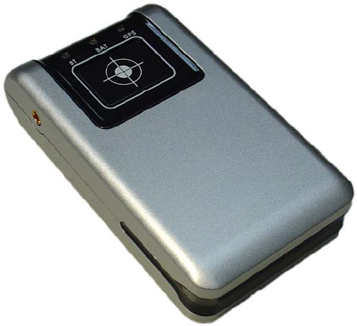
Bluetooth GPS Receiver
User’s Guide
Sep 6, 2005 V 1.1
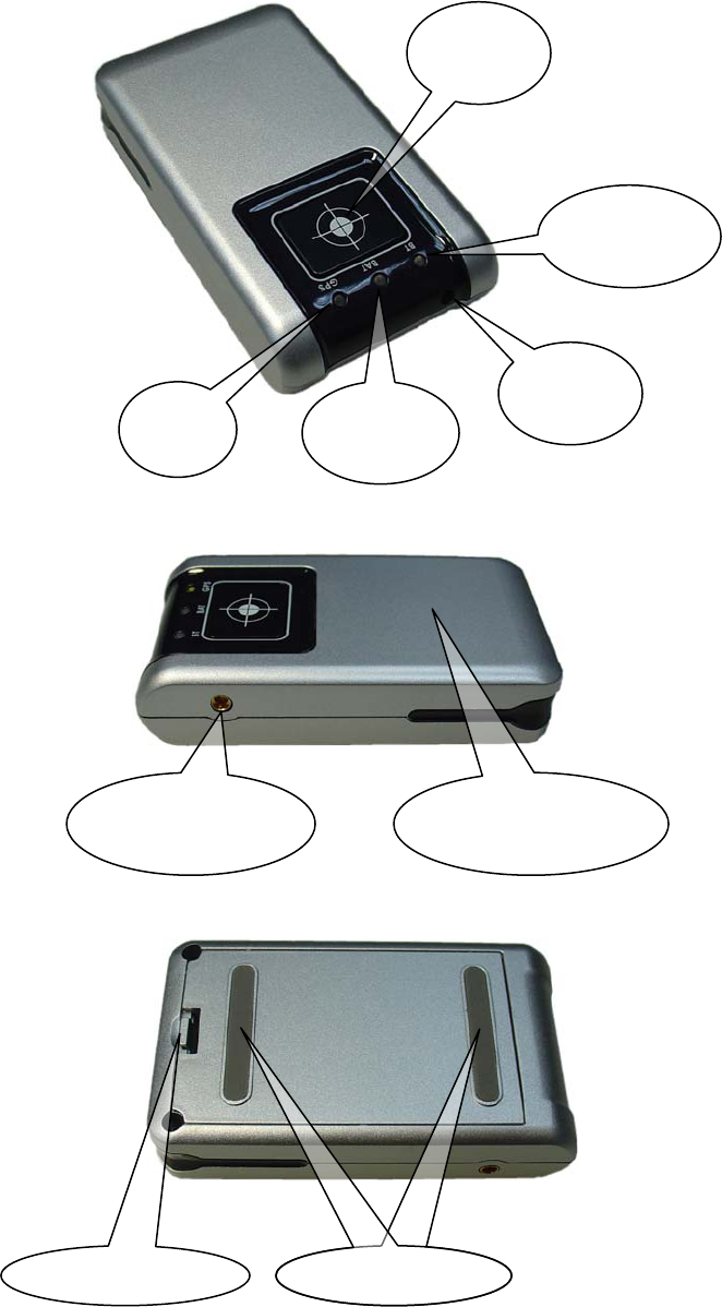
Quick Tips
Power
Button
Bluetooth
LED
Battery
LED
GPS
LED
Power
Jack
External
Antenna Port Internal
Antenna (Hide)
Battery Bolt Slip-resistant Slip-resistant
Introduction
BG-200 is the NEMERIX chip set Bluetooth GPS receiver with compact size,
light weight and ultra low power consumption making an idea solution to
carry every where. The GPS receiver combines with Bluetooth wireless
technologies that give your computing device really mobile.
Features
z NEMERIX chip set.
z 16 parallel Channel.
z High sensitivity up to -152dBm.
z Compact design with light weight.
z Ultra long working time up to 24 hours.
z Integrated Bluetooth transceiver.
z Band rat 38400bps,Data bit 8,n,1
z External antenna port for MMCX antenna.
Application
z PC, PDA and smart phone navigation
z Fleet management
z Automotive vehicle tracking.
z Sports and recreation.
z Geographic surveying.

Getting Started
1. Fully charge battery.
Install battery. Charge battery for at least eight hours before first use.
Battery low Battery LED flashes red light. Battery power is
critically low. Connect Power Jack to a power
source for continue operation and recharge
simultaneously.
Charging Battery LED keep red light when battery is being
charged. Battery LED turns off when the battery
has been fully charged.
2. Turn on Receiver.
Press the Power Button for 3 second or until GPS LED turns into green
light, and the Bluetooth LED turns to blue flashing light.
3. Connect to Bluetooth-Enabled Device.
From your Bluetooth-Enable execute Bluetooth application software to
search "BT GPS" and then connect it to device. If connection is
successful, the Bluetooth LED will blink twice every 3 seconds.
(Pin code may require during configuration. Code=0000)
4. Connect to your Navigation Software.
Start the application. Make sure the application is set for the COM port
that your Bluetooth-Enable device will use for serial communication.
Now you should be ready to use your Navigation software. Refer to user
documents that came with software. More configurations may be
necessary.
5. About LED signals
6. Turn off Receiver
Press power button for 3 seconds or until GPS LED turns off. At the
point, power will be automatically shut off.
(Note: Suggest Navigation Software be turned off before GPS Receiver,
to avoid possible PDA /PC freeze.)
(Note: Bluetooth GPS operates on OS with Bluetooth function that
supports SPP, Band rat 38400,Data bit 8,n,1)
a. Green light, blinking with long dark indicates GPS
is tracking. Not fix the position.
GPS
LED
b
. Green light, blinking with short dark indicates GPS
fix the position .
Power
LED Flashes red light. Battery power is critically low.
a. Blue light, flashing once every 3 seconds.
Bluetooth not connected
Bluetooth
LED b. Blue light, flashing twice every 3 seconds.
Bluetooth connected
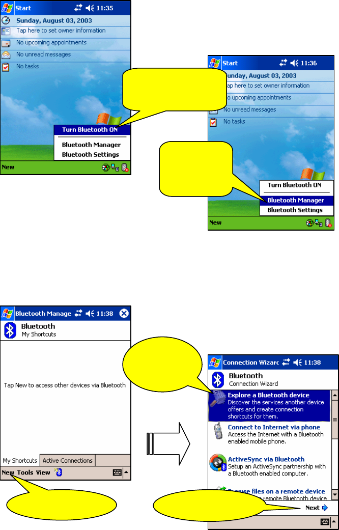
PDA Configuration
1. Activate Bluetooth function of your PDA
Prior to activating the Bluetooth function of your PDA, make sure the
device is equipped with Bluetooth function, and the driver software has
been installed.
1. Click To Turn
Bluetooth ON
2. Go into
Bluetooth
Manager
2. Activate Bluetooth Manager & Established New Connections
Illustrations using HP iPaq 4150 PDA as follows:
First, find the device with which you wish to establish connection.
Open “Bluetooth Manager” on your pocket pc.
3. Click New
4. Select
This
5. Click Next
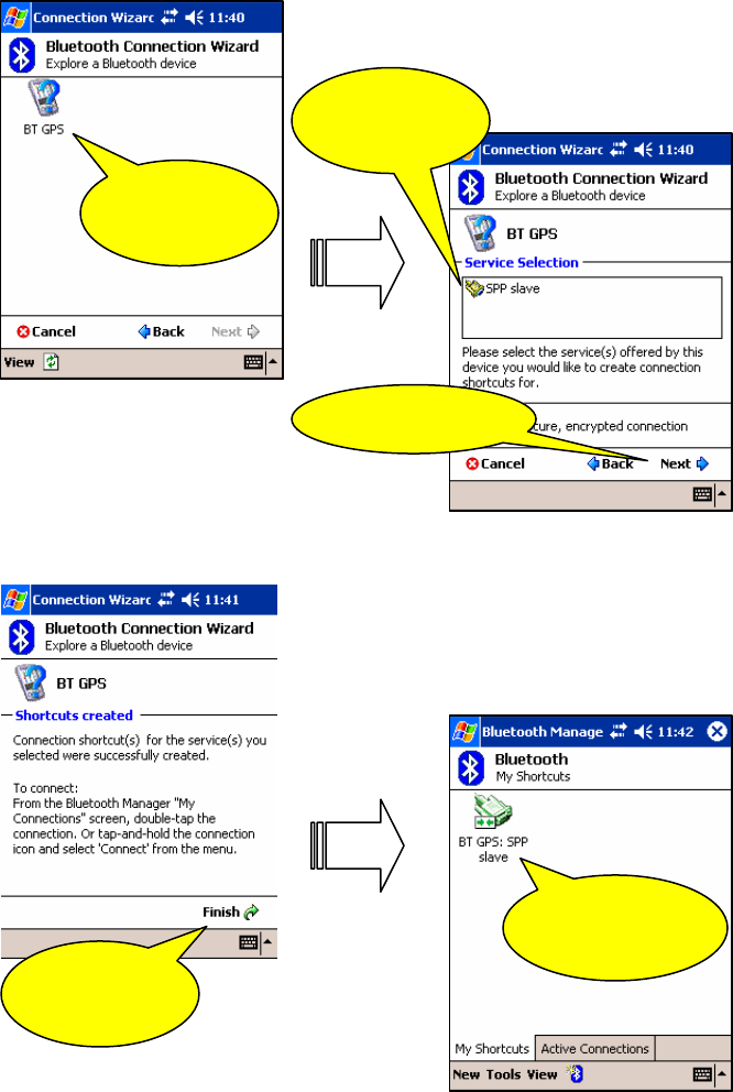
6. Select
"BT GPS"
7. Select
SPP Slave
8. Click Next
At this point, Bluetooth GPS connection has been successfully established
9. Finish
Setting
10. Click To
Connect
When Bluetooth LED flashes twice every 3 seconds, it’s indicating Bluetooth
GPS and the PDA connection are in progress.
Specifications
GPS Receiver
GPS chip NEMERIX
Frequency L1, 1575.42Mhz
C/A code 1.023MHz
Channel 16 parallel channel
Sensitivity -152dBm
Cold start 60 seconds
Warm start 38 seconds
Hot start 12 seconds
Reacquisition 1 second
Bluetooth
Chip CSR
Frequency 2.4GHz
Output Power +4dBm
Input Sensitivity -80dBm
Cover age 10m
Band Rad 38400bps
Data bit 8,n,1
Device ID BT GPS
Pass Key 0000
Power
Battery type Li-ion 3.7V 1000mAh
Operation Current 40mA
Operation Time 24 hours
Charging Time 3.5 hours
Power Jack 5.1V DC input with 500mA
Environmental
Operation Temperature -20°C to +60°C
Relative Humidity 5% to 90%
Outline
Body Size 77(L)x44(W)x17.5(H)mm
Weight 85g
Power Jack 2.5mm diameter
External Antenna Port Active MMCX antenna port
Power Button Power on/off
GPS LED GPS status.
BAT LED Battery power status.
BT LED Bluetooth connection status.

NMEA Protocol
The receiver is capable of supporting the following NMEA message
formats
NMEA
Message Prefix Format Direction
$GPGGA(1)* GPS fix data. Out
$GPGLL Geographic position Latitude / Longitude. Out
$GPGSA(3)* GNSS DOP and actives satellites Out
$GPGSV(3)*
Satellites in view. Out
$GPRMC(1)* Recommended minimum specific GNSS data. Out
$GPVTG(1)*
Velocity and track over ground. Out
$GPZDA Date and time. Out
*: (1): 1sec output 1msg , (3): 3sec output 1msg , 38400 baud rate (Standard output)

NMEA Extensions
The receiver is capable of supporting the following NMEA extensions:
NMEA
Message Prefix Format Direction
$PNMRX100 Set serial port parameters. In
$PNMRX101 Navigation initialization In
$PNMRX103 NMEA message rate control In
$PNMRX104 LLA navigation initialization In
$PNMRX106 Set Datum. In
$PNMRX107 NemeriX messages rate control In
$PNMRX108 NMEA message sequence control In
$PNMRX110 Fix Settings In
$PNMRX111 Software Reset In
$PNMRX112 Operating Mode Control In
$PNMRX113 Fix and Extraction control In
$PNMRX300 Almanac data transfer In / Out
$PNMRX301 Ephemeris data transfer. Out
$PNMRX302 Ionospheric correction Out
$PNMRX303 UTC Time Out
$PNMRX304 GPS Constellation Health Status Out
$PNMRX600 SW Version report Out
$PNMRX601 ISP mode In
$PNMRX602 Flash content version report Out
$PNMRX603 Settings Report Out
General NMEA Format
The general NMEA format consists of an ASCII string commencing with
a ‘$’ character and terminating with a <CR><LF> sequence. NMEA standard
messages commence with ‘GP’ then a 3-letter message identifier. NemeriX
specific messages commence with $PNMRX followed by a 3 digit number.
The message header is followed by a comma delimited list of fields
optionally terminated with a checksum consisting of an asterix ‘*’ and a 2
digit hex value representing the checksum. There is no comma preceding the
checksum field. When present, the checksum is calculated as a byte wise
exclusive of the characters between the ‘$’ and ‘*’. As an ASCII
representation, the number of digits in each number will vary depending on
the number and precision, hence the record length will vary. Certain fields
may be omitted if they are not used, in which case the field position is
reserved using commas to ensure correct interpretation of subsequent fields.
The tables below indicate the maximum and minimum widths of the
fields to allow for buffer size allocation.

$GPGGA
This message transfers global positioning system fix data. The $GPGGA
message structure is shown below:
Field Format
Min
chars Max
chars Notes
Message ID $GPGGA 6 6 GGA protocol header.
UTC Time hhmmss.sss 2,2,2.3 2,2,2.
3 Fix time to 1ms accuracy.
Latitude float 3,2.4 3,2.4 Degrees * 100 + minutes.
N/S Indicator char 1 1 N=north or S=south
Longitude float 3,2.4 3,2.4 Degree * 100 + minutes.
E/W
indicator
Char 1 1 E=east or W=west
Position Fix
Indictor
Int 1 1
0: Fix not available or invalid. 1: GPS
SPS mode. Fix available.
Satellites
Used
Int 2 2 Number of satellites used to calculate fix.
HDOP Float 1.1 3.1 Horizontal Dilution of Precision.
MSL Altitude Float 1.1 5.1 Altitude above mean seal level
Units Char 1 1 M Stands for “meters”.
Geoid
Separation
Int (0) 1 4 Separation from Geoid, can be blank.
Units Char 1 1 M Stands for “meters”.
Age of
Differential
Corrections
int (0) 1 5 Age in seconds Blank (Null) fields when
DGPS is not used.
Diff
Reference
Corrections
int 4 4 0000.
Checksum *xx (0) 3 3 2 digits.
Message
terminator
<CR>
<LF> 2 2 ASCII 13, ASCII
10.

$GPGLL
This message transfers Geographic position, Latitude, Longitude, and
time. The $GPGLL message structure is shown below:
Field Format
Min
chars Max
chars Notes
Message ID $GPGLL 6 6 GLL protocol header.
Latitude Float 1,2.1 3,2.4 Degree * 100 + minutes.
N/S Indicator Char 1 1 N=north or S=south.
Longitude Float 1,2.1 3,2.4 Degree * 100 + minutes.
E/W indicator Character 1 1 E=east or W=west.
UTC Time hhmmss.sss 1,2,2.1 2,2,2.3 Fix time to 1ms accuracy.
Status Char 1 1
A Data Valid. V Data invalid.
Mode
Indicator Char 1 1 A Autonomous
Checksum *xx (0) 3 3 2 digits.
Message
terminator <CR><LF> 2 2 ASCII 13, ASCII 10.

$GPGSA
This message transfers DOP and active satellites information. The
$GPGSA message structure is shown below:
Field Format
Min
chars Max
chars Notes
Message ID $GPGSA 6 6 GSA protocol header.
Mode Char 1 1 M Manual, forced to operate in selected
mode. A Automatic switching between
modes.
Mode Int 1 1 1 Fix not available. 2 2D position fix. 3
3D position fix.
Satellites
Used Int 2 2 SV on channel 1.
Satellites
Used Int 2 2 SV on channel 2.
… . .. .. ..
Satellites
Used Int 2 2 SV on channel 12.
PDOP Float 1.1 3.1
HDOP Float 1.1 3.1
VDOP Float 1.1 3.1
Checksum *xx 0 3 2 digits
Message
terminator <CR>
<LF> 2 2 ASCII 13, ASCII 10

$GPGSV
This message transfers information about satellites in view. The $GPGSV
message structure is shown below. Each record contains the information for
up to 4 channels, allowing up to 12 satellites in view. In the final record of
the sequence the unused channel fields are left blank with commas to
indicate that a field has been omitted.
Field Format
Min
chars Max
chars Notes
Message ID $GPGSV 6 6 GSA protocol header.
Number of
messages Int 1 1
Number of messages in the message
sequence from 1 to 3.
Message
number Int 1 1
Sequence number of this message in
current sequence, form 1 to 3.
Satellites in
view Int 1 2 Number of satellites currently in view.
Satellite Id Int 2 2 Satellite vehicle 1.
Elevation Int 1 3 Elevation of satellite in degrees.
Azimuth Int 1 3 Azimuth of satellite in degrees.
SNR Int (0) 1 2 Signal to noise ration in dBHz, null if the
sv is not in tracking.
Satellite Id Int 2 2 Satellite vehicle 2.
Elevation Int 1 3 Elevation of satellite in degrees.
Azimuth Int 1 3 Azimuth of satellite in degrees.
SNR Int (0) 1 2 Signal to noise ration in dBHz, null if the
sv is not in tracking.
Satellite Id Int 2 2 Satellite vehicle 3.
Elevation Int 1 3 Elevation of satellite in degrees.
Azimuth Int 1 3 Azimuth of satellite in degrees.
SNR Int (0) 1 2 Signal to noise ration in dBHz, null if the
sv is not in tracking.
Satellite Id Int 2 2 Satellite vehicle 4.
Elevation Int 1 3 Elevation of satellite in degrees.
Azimuth Int 1 3 Azimuth of satellite in degrees.
SNR Int (0) 1 2 Signal to noise ration in dBHz, null if the
sv is not in tracking.
Checksum *xx (0) 3 3 2 digits.
Message
terminator <CR>
<LF> 2 2 ASCII 13, ASCII 10.

$GPRMC
This message transfers recommended minimum specific GNSS data. The
$GPRMC message format is shown below.
Field Format
Min
chars Max
chars Notes
Message ID $GPRMC 6 6 RMC protocol header.
UTC Time hhmmss.sss 1,2,2.1 2,2,2.3 Fix time to 1ms accuracy.
Status char 1 1
A Data Valid. V Data invalid.
Latitude Float 1,2.1 3,2.4 Degrees * 100 + minutes.
N/S Indicator Char 1 1 N=north or S=south.
Longitude Float 1,2.1 3,2.4 Degrees * 100 + minutes.
E/W indicator Char 1 1 E=east or W=west.
Speed over
ground Float 1,1 5.3 Speed over ground in knots.
Course over
ground Float 1.1 3.2 Course over ground in degrees.
Date ddmmyy 2,2,2 2,2,2 Current date.
Magnetic
variation Blank (0) (0) Not used.
E/W indicator Blank (0) (0) Not used.
Mode Char 1 1 A Autonomous
Checksum *xx (0) 3 3 2 digits.
Message
terminator <CR>
<LF> 2 2 ASCII 13, ASCII 10.

$GPVTG
This message transfers Velocity, course over ground, and ground speed.
The $GPVTG message format is shown below.
Field Format
Min
chars Max
chars Notes
Message ID $GPVTG 6 6 VTG protocol header.
Course (true) Float 1.1 3.2 Measured heading in degrees.
Reference Char 1 1 T = true heading.
Course
(magnetic) Float 1.1 3.2 Measured heading (blank).
Reference Char 1 1 M = magnetic heading.
Speed Float 1.1 4.2 Speed in knots.
Units Char 1 1 N = knots.
Speed Float 1.1 4.2 Speed
units Char 1 1 K = Km/h.
Mode Char 1 1 A Autonomous
Checksum *xx (0) 3 3 2 digits.
Message
terminator <CR>
<LF> 2 2 ASCII 13, ASCII 10.

$GPZDA
This message transfers UTC Time and Date. Since the latency of
preparing and transferring the
message is variable, and the time does not refer to a particular position
fix, the seconds precision is
reduced to 2 decimal places. The $GPZGA message format is shown
below.
Field Format
Min
chars Max
chars Notes
Message ID $GPZDA 6 6 ZDA protocol header.
UTC time hhmmss.ss 2,2,2.2 2,2,2.2 00000000.00 to 235959.99
UTC day dd 2 2 01 to 31, day of month.
UTC month mm 2 2 01 to 12.
UTC Year yyyy 4 4 1989-9999.
Local zone
hours Int (-)2 (-)2 Offset of local time zone (-13) to 13.
Local zone
minutes Unsigned 2 2
Checksum *xx (0) 3 3 2 digits.
Message
terminator <CR>
<LF> 2 2 ASCII 13, ASCII 10.
Federal Communications Commission (FCC) Statement
15.21
You are cautioned that changes or modifications not expressly approved by
the part responsible for compliance could void the user’s authority to operate
the equipment.
15.105(b)
This equipment has been tested and found to comply with the limits for a
Class B digital device, pursuant to part 15 of the FCC rules. These limits are
designed to provide reasonable protection against harmful interference in a
residential installation. This equipment generates, uses and can radiate radio
frequency energy and, if not installed and used in accordance with the
instructions, may cause harmful interference to radio communications.
However, there is no guarantee that interference will not occur in a particular
installation. If this equipment does cause harmful interference to radio or
television reception, which can be determined by turning the equipment off
and on, the user is encouraged to try to correct the interference by one or
more of the following measures:
-Reorient or relocate the receiving antenna.
-Increase the separation between the equipment and receiver.
-Connect the equipment into an outlet on a circuit different from that to
which the receiver is connected.
-Consult the dealer or an experienced radio/TV technician for help.
Operation is subject to the following two conditions:
1) this device may not cause interference and
2) this device must accept any interference, including interference that may
cause undesired operation of the device.
FCC RF Radiation Exposure Statement:
This equipment complies with FCC radiation exposure limits set forth for an
uncontrolled environment. End users must follow the specific operating
instructions for satisfying RF exposure compliance. This transmitter must not
be co-located or operating in conjunction with any other antenna or
transmitter.
Note: The end product shall has the words “Contains Transmitter Module
FCC ID: SMW56AZBT or Contains FCC ID: SMW56AZBT” on the ID
label