ELITEGROUP COMPUTER SYSTEMS G553IBXX Notebook PC with 802.11b WLAN User Manual G553 user namual update
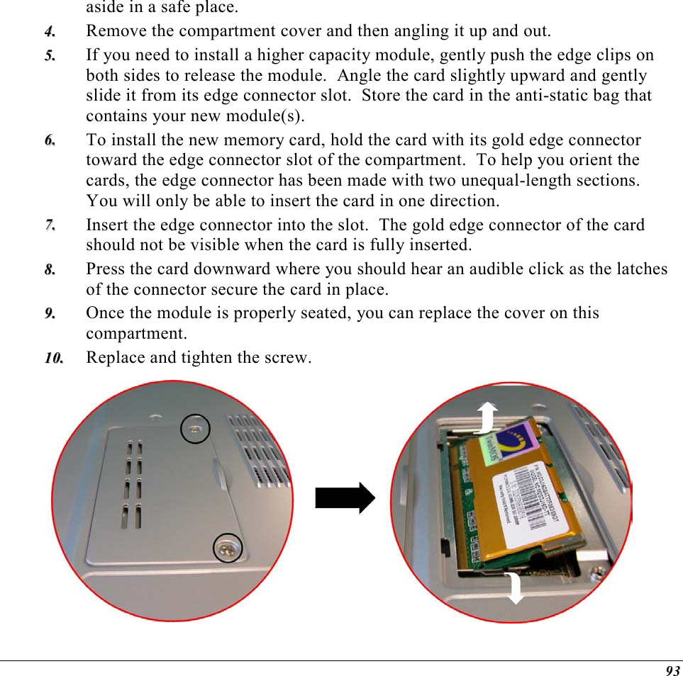
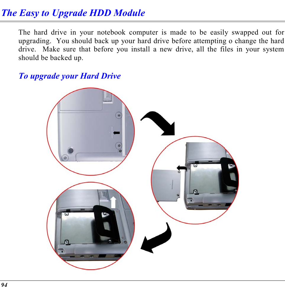
Elitegroup Computer Systems Co., Ltd Notebook PC with 802.11b WLAN G553 user namual update
Contents
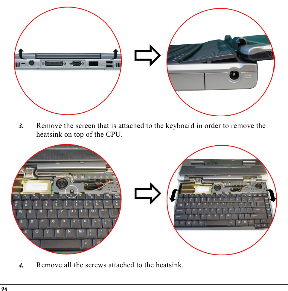
- 1. Users Manual Part 1 Revision 2
- 2. Users Manual Part 2 Revision 2
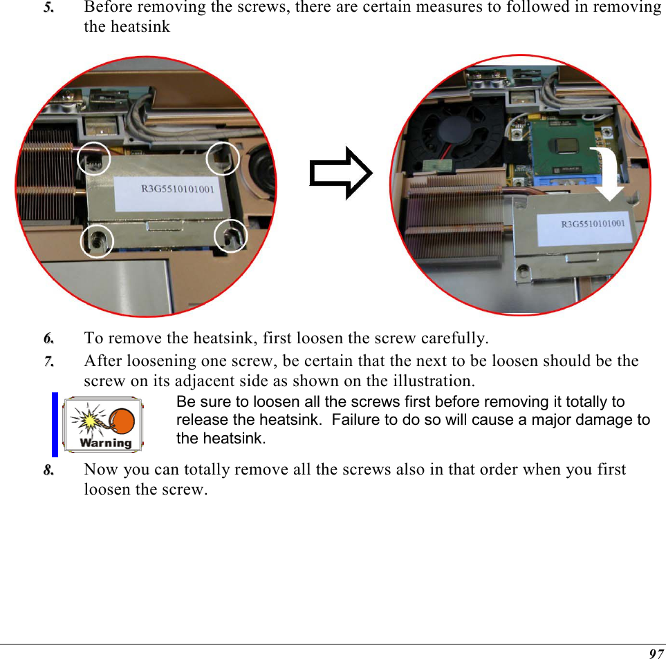
Users Manual Part 2 Revision 2

![62 Minus key (-) Scrolls backward through the values for the highlighted field. Plus key (+) Scrolls forward through the values for the highlighted field. Home PgUp Moves the cursor to the field at the top of the window. End PgDn Moves the cursor to the field at the bottom of the window. F9 Sets the parameters for the current menu to their default values. F10 Save and Exit. Enter Will select a sub menu or show a range of options for a field. Launching Submenus Note that a right pointer symbol υ appears to the left of certain fields. This pointer indicates that a submenu can be launched from this field. A submenu contains additional options for a field parameter. To call up a submenu, simply move the cursor to highlight the field and press the [Enter] key. Use the [Esc] key to return to the Main menu. General Help In addition to the Item Specific Help window, the BIOS Setup program also provides a General Help screen can be called up from any menu by simply pressing [F1].](https://usermanual.wiki/ELITEGROUP-COMPUTER-SYSTEMS/G553IBXX.Users-Manual-Part-2-Revision-2/User-Guide-466178-Page-7.png)
![63 Use the [PgUp] and [PgDn] keys or the up and down arrow keys (↑↓) to scroll through the entire help document. Press the Home key to display the first page, press End to go to the last page. To exit the help window, press the [Enter] or the [Esc] key. Save Changes and Exit the Setup Program Refer to the Exit menu section of this chapter for detailed information on saving changes and exiting the setup program. The Main Menu When the Setup program is accessed, the following screen appears:](https://usermanual.wiki/ELITEGROUP-COMPUTER-SYSTEMS/G553IBXX.Users-Manual-Part-2-Revision-2/User-Guide-466178-Page-8.png)