ELITEGROUP COMPUTER SYSTEMS WCPTI-S WPC Module User Manual Vector Smart Object
ELITEGROUP COMPUTER SYSTEMS CO., LTD WPC Module Vector Smart Object
User Manual
User Guide
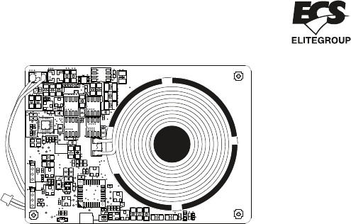
WPC Module
WCPTI-S
RDCH
RGPD
C4
C5
TP11
JP2
M8
M6
LED4
R8
RTVQ
RSDA
RSCL
RQPD
RGPU
CSDA
CSCL
CPA2
TP10
TP2
TP9
TP4
TP5
JP1
OSC
M3
DVQ
RVQ2
RVQ1
RSINP
RSINL
C2
TP8
CDC2
CDC1
COM-CH
VIN
RQOUT2
RQOUT1
CAIN0
TP13
TP15
U3
M4
RLD1
CAIN1
TP16
TP18
M10
U2
RHD1
CAPD1
MOS_L2
RS1
RS2
M7
CADP4
CADP3
M1
M5
RCOILL2
CCOILV2
RQIN1
RQIN2
RCOILL
RCOILH
RREFH2
RREFH1
RREFH
TUOXCTR CSOR
COSC1
CPA
COSC2
U1
CBOOT2
RTVIN
CVIN1
CV33B
CV33A
TP1
TP6
MOS_L1
MOS_H2MOS_H1 M9
DTVIN
CADP2
RVIN2
RVIN3
CBOOT1
RH1
CQOUT2
RADC
DCOIL
RPPHRPPG
RPPEN
CADP5
TP7
M2
RVIN1
8
+
+
2
+
40
+
B
A
E
GND
+
C
A
D
C
B
D
E
15-KS3-051001
WCPTI-S V:1.0
RLED2
RLED3
RLED1
CREFH1
TP3
TP12
TP21
TP20
TP19
C8
C9
CCLMP
CADC
RCLMP
RVDL
RVDL2
MP
CCOILV
RVDH
RL1
RLD2
RHD2
CS1
CS2
CS3
RH2
RL2
RSOUT
U4
CSIN
CSOUT
CQOUT1
DCLMP
+
Interface
RDCH
RGPD
C4
C5
TP11
JP2
M8
M6
LED4
R8
RTVQ
RSDA
RSCL
RQPD
RGPU
CSDA
CSCL
CPA2
TP10
TP2
TP9
TP4
TP5
JP1
OSC
M3
DVQ
RVQ2
RVQ1
RSINP
RSINL
C2
TP8
CDC2
CDC1
COM-CH
VIN
RQOUT2
RQOUT1
CAIN0
TP13
TP15
U3
M4
RLD1
CAIN1
TP16
TP18
M10
U2
RHD1
CAPD1
MOS_L2
RS1
RS2
M7
CADP4
CADP3
M1
M5
RCOILL2
CCOILV2
RQIN1
RQIN2
RCOILL
RCOILH
RREFH2
RREFH1
RREFH
TUOXCTR CSOR
COSC1
CPA
COSC2
U1
CBOOT2
RTVIN
CVIN1
CV33B
CV33A
TP1
TP6
MOS_L1
MOS_H2MOS_H1 M9
DTVIN
CADP2
RVIN2
RVIN3
CBOOT1
RH1
CQOUT2
RADC
DCOIL
RPPHRPPG
RPPEN
CADP5
TP7
M2
RVIN1
8
+
+
2
+
40
+
B
A
E
GND
+
C
A
D
C
B
D
E
15-KS3-051001
WCPTI-S V:1.0
RLED2
RLED3
RLED1
CREFH1
TP3
TP12
TP21
TP20
TP19
C8
C9
CCLMP
CADC
RCLMP
RVDL
RVDL2
MP
CCOILV
RVDH
RL1
RLD2
RHD2
CS1
CS2
CS3
RH2
RL2
RSOUT
U4
CSIN
CSOUT
CQOUT1
DCLMP
+
1
1
2
2
3
3
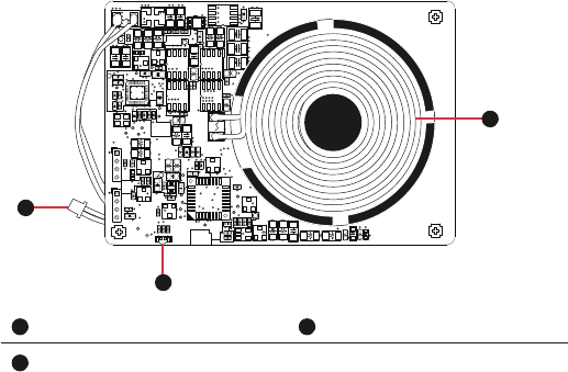
Charging Coil
Power Cable(Black for Ground; Red for DC Input)
LED Indicator

Dimension
Transmier IC
Charging Method
Coil Type
Operang Temperature
Operang Frequency
86.0 mm x 60.0 mm x 6.1 mm
Rohm, BD50720MWV
Magnec Inducon
MP-A7(19V)
43.0 mm x 20.5 mm x 2.1 mm
0~40 ˚C
110K~205K
The WCPTI-S is designed for wireless charger applicaon. It supports 5 and 15 wa receiver
soluon. When WCPTI-S connects correctly to a PC, you need to place a supported charger
device on the WCPTI-S, then you can see the indicator to show behavior.
WCPTI-S has a few behavior to show status that you can check as below:
Operation Description
Specification
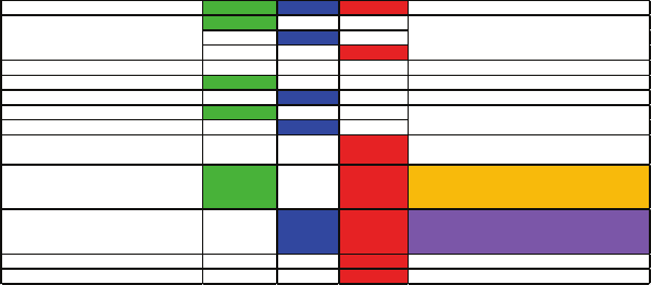
WCPTI-S LED behavior LED1: Green LED2: Blue LED3: Red Remark
ON OFF OFF
OFF ON OFF
OFF OFF ON
S
tandby OFF OFF OFF
C
harging-LOW Power Blinking OFF OFF
Blinking 500ms
C
harging-Middle Power OFF Blinking OFF Blinking 500ms
C
harging Complete- Low Power ON OFF OFF
C
harging Complete- Middle Power OFF ON OFF
E
rror-1 FOD OFF OFF Blinking(0.2S)
1.When Rx was removed, Tx cancel the error state
2. 200ms
E
rror-2 Power restricon- Low Power ON OFF Blinking(1S)
1.When Rx was removed, Tx cancel the error state
2. 1s
3. Show orange LED
E
rror-2 Power restricon- Middle Power OFF ON Blinking(1S)
1.When Rx was removed, Tx cancel the error state
2. 1s
3. Show purple LED
E
rror-3 OCP OTP… OFF OFF ON When Rx was removed, Tx cancel the error state
Error-4 TSD OFF OFF ON When Rx was removed, Tx cancel the error state
G=500ms
B= 500ms
R= 500ms
P
ower on(G>B>R>OFF)
Keep lighng unl 30 mins, then show standby
status (If RX didn’t remove)
LED Behavior

Notice and Safety
Any changes or modifications not expressly approved by the grantee of this device could void the user's authority to
operate the equipment.
Declaration the Restriction of this Limited Module Approval:
According to FCC Part 15 Subpart C Section 15.212, the radio elements of the modular transmitter must have their own
shielding. However, due to there is no shielding for this Module, this module is granted as a Limited Modular Approval.
When this Module is installed into the end product, a Class II Permissive Change or a New FCC ID submission is required
to ensure the full compliance of FCC relevant requirements.
10cm minimum distance has to be able to be maintained between the antenna and the users for the host this module is
integrated into. Under such configuration, the FCC radiation exposure limits set forth for an opulation/uncontrolled
environment can be satisfied.
Only FCC approved antenna can be used for the module integrated into host.
LABEL OF THE END PRODUCT:
The final end product must be labeled in a visible area with the following" Contains TX FCC ID: WL6WCPTI-S".
FCC Label Compliance Statement:
This device complies with Part 15 of the FCC Rules. Operation is subject to the following two conditions:
(1) This device may not cause harmful interference
(2) This device must accept any interference received, including interference that may cause undesired operation.
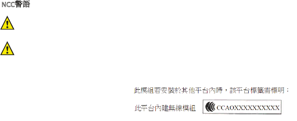
經型式認證合格之低功率輻射電機,非經許可,公司、商號或使用者均不得擅自變更頻率、
加大功率或變更原設計之特性及功能。
低功率射頻電機之使用不得影響飛航安全及干擾合法通信;經發現干擾現象時,應立即停用,
並改善至無干擾時方得繼續使用。前項合法通信,指依電信法規作業之無線電通信。低功率
射頻電機須忍受合法通信或工業、科學及醫療用電波輻射性電機設備之干擾。
NCC警語
Golden Elite Technology ( SHENZHEN ) CO., LTD.
Address: No.1, Nan-Huan Rd., ShaJing, BaoAn,
Shenzhen, China