ELPRO Technologies S2900 Wireless Modem Module User Manual 945U E
ELPRO Technologies Pty Ltd Wireless Modem Module 945U E
User Manual
Version 1.2
S2900 Radio Module
Integrator Installation Manual
Read and
Retain for
Future
Reference

Elpro Technologies E2-450 Radio Transceiver Module Instruction Manual
2 www.cooperbussmann.com/wirelessresources Rev Version
1.0
ATTENTION!
Incorrect termination of the supply wires may cause internal damage. Before turning the power on double-check ALL
connections by referring to this User Manual.
CAUTION
To comply with FCC RF Exposure requirements in section 1.1310 of the FCC Rules, antennas used with this device
must be installed to provide a separation distance of at least 90 cm from all persons to satisfy RF exposure
compliance.
DO NOT
Operate the transmitter when anyone is within 90 cm of the antenna.
Operate the transmitter unless all RF connectors are secure and any open connectors are properly
terminated.
Operate the equipment near electrical blasting caps or in an explosive atmosphere.
All equipment must be properly grounded for safe operations. All equipment should be serviced only by a qualified
ELPRO staff only.
FCC Notice:
Part 90 – This device has been type accepted for operation by the FCC in accordance with Part90 of the FCC rules
(47CFR Part 90). See the label on the unit for the specific FCC ID and any other certification designations.
Note: This device should only be connected to Devices that are covered by either a FCC DoC or
are FCC certified.
Antenna Models:
Manufacturer
Model Number
Net
ELPRO
CFD940
2 dBi Gain
ELPRO
SG900EL
5 dBiGain
ELPRO
SG940-6
8 dBi Gain
ELPRO
YU6-940
11 dBi Gain

Elpro Technologies E2-450 Radio Module Instruction Manual
Rev Version 1.0 www.cooperbussmann.com/wirelessresources 3
Safety Notices:
Exposure to RF energy is an important safety consideration. The FCC has adopted a safety standard for human
exposure to radio frequency electromagnetic energy emitted by FCC regulated equipment as a result of its actions in
Docket 93-62 and OET Bulletin 65 Edition 97-01.
User Notification
THIS DEVICE COMPLIES WITH PART 15 OF THE FCC RULES. OPERATIONIS SUBJECT TO THE FOLLOWING
TWO CONDITIONS: (1) THIS DEVICE MAY NOT CAUSE HARMFUL INTERFERENCE, AND (2) THIS DEVICE
MUST ACCEPT ANY INTERFERENCE RECEIVED, INCLUDING INTERFERENCE THAT MAY CAUSE UNDESIRED
OPERATION.
NOTE: THE GRANTEE IS NOT RESPONSIBLE FOR ANY CHANGES OR MODIFICATIONS NOT EXPRESSLY
APPROVED BY THE PARTY RESPONSIBLE FOR COMPLIANCE. SUCH MODIFICATIONS COULD VOID THE
USER’S AUTHORITY TO OPERATE THE EQUIPMENT
This device complies with Industry Canada’s licence-exempt RSSs. Operation is subject to the following two
conditions: (1) This device may not cause interference; and (2) This device must accept any interference, including
interference that may cause undesired operation of the device.
Le présent appareil est conforme aux CNR d'Industrie Canada applicables aux appareils radio exempts de licence.
L'exploitation est autorisée aux deux conditions suivantes : (1) l'appareil ne doit pas produire de brouillage, et (2)
l'utilisateur de l'appareil doit accepter tout brouillage radioélectrique subi, même si le brouillage est susceptible d'en
compromettre le fonctionnement.
Modular Limitations and Condition of Use
ELPRO S2900 radio module is designed as a reusable module for use with future development of ELPRO products.
The module is limited for use by ELPRO only. This module is not to be made available for third party use or in any
OEM arrangements.
The integrator is responsible for ensuring that the end-user has no manual instruction to remove or install module.
The separate approval is required for all other operation configurations, including portable configuration with respect to
Part 2.1093 and different antenna configuration.
The module is limited to installation in mobile or fixed applications, according to Part 2.1091 (b).

Elpro Technologies E2-450 Radio Transceiver Module Instruction Manual
4 www.cooperbussmann.com/wirelessresources Rev Version
1.0
CONTENTS
CHAPTER 1 - INTRODUCTION ...................................... 5
CHAPTER 2 - Module Description ................................... 5
CHAPTER 3 - Main Host Interface .................................. 5
Alternate Host Interface ................................................... 6
Production Interfaces ....................................................... 6
CHAPTER 4 - OPERATION ............................................. 6
CHAPTER 5 - Locale ..................................................... 12
CHAPTER 6 - Interface Pin Description ........................ 12
Main Host Interface Pin Description ............................... 12
CHAPTER 7 - Protective Earthing Point ........................ 13
CHAPTER 8 - SPECIFICATIONS .................................. 13
Elpro Technologies E2-450 Radio Module Instruction Manual
Rev Version 1.0 www.cooperbussmann.com/wirelessresources 5
CHAPTER 1 - INTRODUCTION
The S2900 is a radio modem module that will be used as a base radio for a number of Elpro wireless products in the
future. It will be primarily used to act as a wireless network adapter for transfer of 802.11 data frames over lower
speed wireless links. The S2900 consists of a host microcontroller, an RF transceiver section, and a power supply
section.
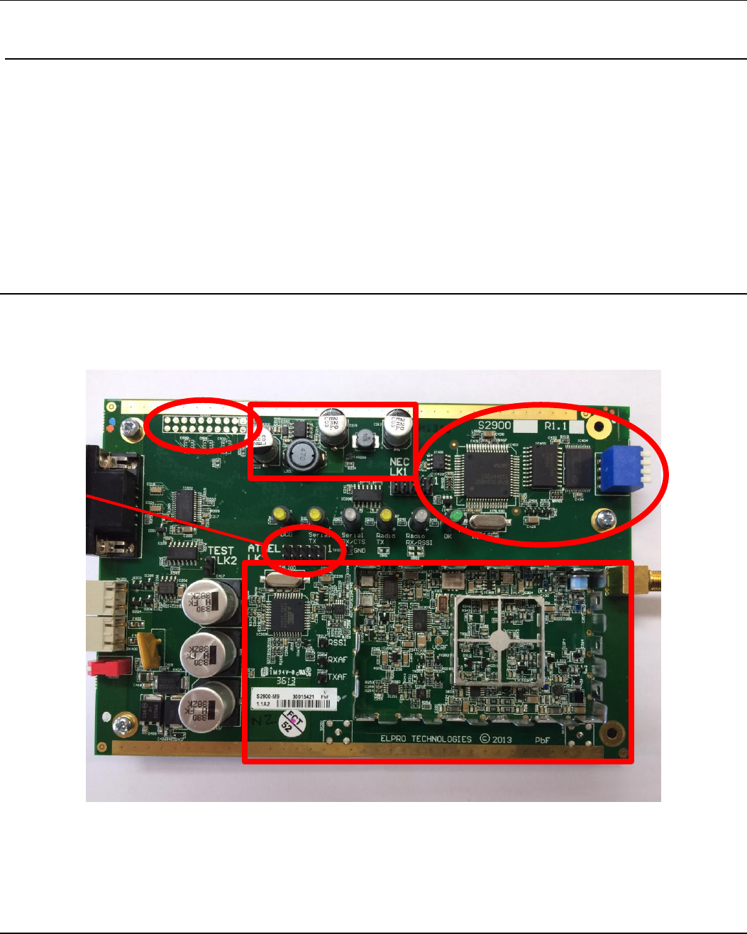
CHAPTER 2 - Module Description
CHAPTER 3 - Main Host Interface
The interface between the radio and the controlling equipment is specified by the electrical and timing information
(Physical Layer) and by the method for transferring data between the controlling equipment and the radio (Link Layer).
The physical interface consists of the following electrical signals:
• BYTE_READY Indication from radio that data has been received
Alternate Host Interface
Production
Interface
Radio Module - Main
Radio Module - Regulators
On Board Host

Elpro Technologies E2-450 Radio Module Instruction Manual
6 www.cooperbussmann.com/wirelessresources Rev Version
1.0
• SELECT Controller selects radio for data transfer
• MISO Synchronous serial data from radio to controller
• MOSI Synchronous serial data from controller to radio
• SCK Serial clock for data transfer between controller and radio
• CMD_ENA Enable Commands after startup is complete.
• CMD_ACK Indicate Radio is ready to receive commands (Rx disabled).
The SELECT, MISO, MOSI, and SCK operate according to the Motorola SPI (Serial Peripheral Interface) standard.
The controller is the SPI master, and the radio is the SPI slave. The BYTE_READY signal allows the slave to indicate
an event to the master. SPI operation is configured for CPOL (Polarity) = 1, and CPHA (Phase) = 1. Data transfer is
most significant bit first.
SCK Idles high. Data changes on the falling edge of SCK, and is sampled on the rising edge of SCK. Eight data bits
are transferred.
The CMD_ENA/CMD_ACK lines enable the use of commands usually disabled after the startup phase is complete –
refer to the section below – “Start Up”.
Alternate Host Interface
The alternate host interface port provides similar signals to the main host interface. This port may be used for future
development.
Production Interfaces
The production interfaces consists of JTAG ports and serial interfaces directly to microcontrollers. These interfaces
are used in production and development only.
CHAPTER 4 - OPERATION
The host system communicates with the S2900 module via the serial peripheral interface. The controller is the SPI
master, and the radio is the SPI slave. The BYTE_READY signal allows the slave to indicate an event to the master.
SPI operation is configured for CPOL (Polarity) = 1, and CPHA (Phase) = 1. Data transfer is most significant bit first.
Data Transfer
Data is transferred from the radio to the controller when receiving a radio transmission and from the controller to the
radio when transmitting on the radio. Other messages may be transferred from the controller to the radio to select
options or to change configuration of the radio.
Data from Controller to Radio
A data transfer from the controller to the radio begins with the controller asserting (lowering) the SELECT signal. The
SPI transfer then proceeds, transferring a command byte as follows:
0xFF
Unused
0xFE
Placeholder Data, Sent when no data to send to radio.
0xFD
Request Country Code (Returns 0,1,2, or 3 for UZ, OZ, NZ, EU)
0xF0 – 0xFA
Configuration Options for Transmit

Elpro Technologies E2-450 Radio Module Instruction Manual
Rev Version 1.0 www.cooperbussmann.com/wirelessresources 7
0xF0
Select Hop Set S1 (Default)
0xF1
Select Hop Set S2
0xF2
Select Hop Set S3
0xF3
Select Hop Set S4
0xF4
Select Hop Set S5
0xF5
Select Hop Set S6
0xF6
Select Hop Set S7
0xF7
Select Hop Set S8
0xF8
Set lead-in to 350 mSec (To wake sleeping slave)
0xF9
Set lead-in to 30 mSec (Default)
0xFA
Set lead-in to 3 mSec (controlled frequency operation)
0xEF
Start Transmission with next hopping sequence frequency
0xEE
Request Signal Strength on current channel
0x80 – 0xE3
Start Transmission with frequency sequence number 0 - 100
0x70 – 0x7F
Configuration Options for Receive
0x70
Unused
0x71
Unused
0x72
Unused
0x73
Set 19,200 baud rate (14,400 for EU Country Code) (Default)
0x74
Unused
0x75
Set 57,600 baud rate (38,400 for EU Country Code)
0x76
Set 115,200 baud rate (76,800 for EU Country Code)
0x78
Set receiver operation to low power slow mode
0x79
Set receiver to normal receive mode (Default)
0x7A
Set Lead-In Frequency to 11 uSec (45.45 kHz)
0x7B
Set Lead-In Frequency to 11.5 uSec (43.48 kHz)
0x7C
Set Lead-In Frequency to 12 uSec (41.67 kHz)
0x7D
Set Lead-In Frequency to 12.5 uSec (40.00 kHz)
0x6F
Set Receiver to scan all channels for incoming signals (Default)
0x00 – 0x63
Set Receiver to frequency sequence number 0 – 100
Note: After Start-Up, all commands except the “Start Transmission” commands must be qualified by holding the
CMD_ENA line low for a until the CMD_ACK line is raised by the radio. The SPI transfer may then proceed. The
CMD_ACK line remains high until a “receive” command comes from the controller.
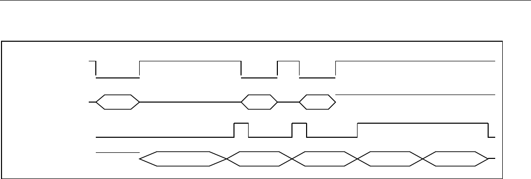
On reception of a Start Transmission command from the controller, the radio begins transmitting a lead-in signal on
the specified frequency. Once the lead-in transmission is complete, the radio begins transmission of the frame
synchronization (SYNC) byte, and simultaneously raises the BYTE_READY line. When the BYTE_READY line is
raised, the controller lowers the SELECT line, and transfers the first byte of data to be sent via the SPI. The radio
lowers the BYTE_READY line when the controller lowers the SELECT line. As the radio completes transmission of the
SYNC byte, it retrieves the first byte of data from the SPI, and again raises the BYTE_READY line. This repeats until
all data is sent. At this time, the controller does not lower the SELECT line, and the radio leaves the BYTE_READY
line high until transmission of the data frame is complete.
Elpro Technologies E2-450 Radio Module Instruction Manual
8 www.cooperbussmann.com/wirelessresources Rev Version
1.0
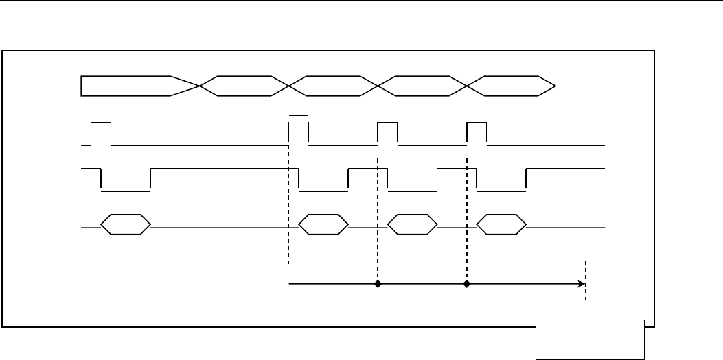
Data from Radio to Controller
Data from the radio to the controller always consists of received radio data. Data transfer is initiated by the radio
raising the BYTE_READY signal. The Controller then lowers the SELECT line, and transfers the data from the radio.
The radio raises the BYTE_READY signal as soon as a radio lead-in is detected. A byte containing the value 0xFF
(Lead-in Found) is transferred to indicate that the radio channel is busy. When the SYNC byte is received over the
radio channel, the radio again lowers the BYTE_READY line. The next byte transferred contains the measured signal
strength (RSSI) of the incoming radio signal. If the lead-in signal is lost, or if the SYNC byte is not detected, the next
byte contains the value 0xFE (Lead-in Lost). Subsequent bytes are the data received over the radio.
SELECT
MOSI
Start Byte 0 Byte 1
BYTE_READY
Radio TX data
Lead-in SYNC Byte 0 Byte 1 End of Frame
Elpro Technologies E2-450 Radio Module Instruction Manual
Rev Version 1.0 www.cooperbussmann.com/wirelessresources 9
Frame reception – valid data frame.
If the radio loses lead-in lock before the sync word is received, then an RSSI value of 0xFE is transferred to indicate
no more data to follow. The Lead-in Found code is 0xFF.
Features to support slow host devices
Host devices which are unable to transfer data to the radio at the 115,200 baud rate must select a slower rate. Several
adaptations are provided to assist in the case of slower host devices.
In the case of 19,200 baud rate, during data transmission, the time between the start of the SYNC word and the start
of the first data byte is shorter than the time between subsequent data bytes. For this reason, the Sync word is
extended to 44 bits when the baud rate is 19,200. This allows the host to respond with the first data byte within the
same time required for subsequent data bytes. (486 uSec).
When the radio detects lead-in, it is possible that “Lead In Lost” may be detected within 110 uSec of the “Lead In
Found” message. Slower host devices may not have completed the transfer of “Lead In Found” indication by this time,
resulting in an overrun condition. If the baud rate is 19,200 baud then the radio delays (up to) an additional 376 uSec
before sending the “Lead In Lost” message. This delay is shorter if the previous SPI transfer has completed.
Contention Resolution
It may occur that the radio begins receiving a data frame at the same time as the controller begins to transfer a
command to the radio. In this case, the controller will transfer a code other than the “Placeholder Data” code 0xFE. If
the radio receives a “Placeholder Data” code when it is transferring the “lead-in-found” code, then it continues
receiving the data. If another code is received, the radio will obey that command, and abort the current receive data
operation.
For example, if the controller begins transmitting at the same time as the radio locks the lead-in. In this case, the
controller will transfer a “Start Transmit” code (0xEF) at the same time as the radio transfers the “lead-in-found” code
(0xFF). In this case, the radio will abort the radio reception, and begin performing the requested transmission. Once
the transfer of the “lead-in-found” code is complete, the radio will ignore subsequent requests from the controller until
the frame reception is complete, or the lead-in is lost (RSSI byte = 0xFE).
Received Signal Strength Indication (RSSI)
The Received signal strength is transferred from the radio at the beginning of the incoming data frame. It is also
possible for the Controller to request the current signal strength when the radio is not receiving data. To do this, the
controller sends the code 0xEE (Request received signal strength). The radio measures the signal strength on the
RX Data
Lead-in SYNC Byte 0 Byte 1 End of Frame
B_RDY
SELECT
MISO
Lead-in Found RSSI Byte 0 Byte 1
End Of Frame Timer (Controller)
Controller Detects
End of Frame

Elpro Technologies E2-450 Radio Module Instruction Manual
10 www.cooperbussmann.com/wirelessresources Rev Version
1.0
current channel then raises the BYTE_READY line to indicate to the controller that the RSSI data is ready. The
controller then transfers the RSSI data from the radio with a second SPI transfer.
Country Code Request
If the Host Controller supports operation in multiple countries, the country code may be requested from the radio. The
host controller sends the code 0xED (Request Country Code). The radio raises the BYTE_READY signal, and makes
the country code value available for SPI transfer. The Host Controller may then read the Country Code by performing
a second SPI Transfer.
Currently defined Country Codes are:
Code
Bit Time
Lead In
Character Time
SYNC Word Time
0xF9
0xFA
0x73
0x75
0x76
0x73
0x75
0x76
0 – US
8.75 uS
30 mS
3 mS
490 uS
175 uS
88 uS
490 uS
220 uS
220 uS
1 – OZ
8.75 uS
30 mS
3 mS
490 uS
175 uS
88 uS
490 uS
220 uS
220 uS
2 – NZ
8.75 uS
30 mS
3 mS
490 uS
175 uS
88 uS
490 uS
220 uS
220 uS
3 – EU
13 uS
5 mS
3 mS
728 uS
260 uS
130 uS
490 uS
220 uS
220 uS
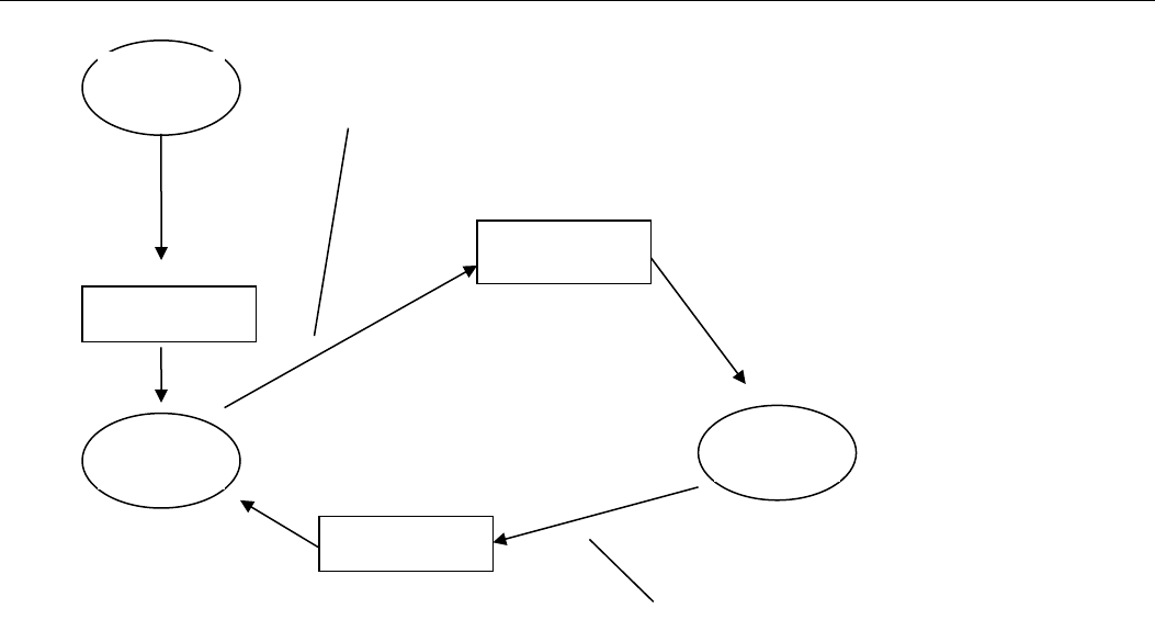
Start-Up
After start-up, the radio ignores all received messages, until the controller sends a “receive” command. This ensures
that any initialisation commands from the controller may be sent without the risk of an incoming radio message
corrupting the commands from the controller. Once the controller sends a receive command, all commands except the
“Start Transmission” commands are disabled. The CMD_ENA and CMD_ACK lines allow commands to be transferred
to the radio after start-up. The controller lowers the CMD_ENA until the CMD_ACK is raised by the radio. The radio
will then stop receiving and accept any commands from the controller until the controller sends a receive command. At
this time, the radio lowers the CMD_ACK line, and begins receiving again.
Elpro Technologies E2-450 Radio Module Instruction Manual
Rev Version 1.0 www.cooperbussmann.com/wirelessresources 11
Radio Lowers
CMD_ACK
Radio Raises
CMD_ACK
Radio Raises
CMD_ACK
START
Comman
d
Receive
Controller
Lowers
CMD_REQ
Controller Sends
“Receive” Command

Elpro Technologies E2-450 Radio Module Instruction Manual
12 www.cooperbussmann.com/wirelessresources Rev Version
1.0
CHAPTER 5 - Locale
The S2900 radio is designed to operate in frequency bands 902 MHz to 928 MHz. These bands are fully supported for
North America.
CHAPTER 6 - Interface Pin Description
Main Host Interface Pin Description
The physical interface consists of the following electrical signals:
• BYTE_READY Indication from radio that data has been received
• SELECT Controller selects radio for data transfer
• MISO Synchronous serial data from radio to controller
• MOSI Synchronous serial data from controller to radio
• SCK Serial clock for data transfer between controller and radio
• CMD_ENA Enable Commands after startup is complete.
• CMD_ACK Indicate Radio is ready to receive commands (Rx disabled).

Elpro Technologies E2-450 Radio Module Instruction Manual
Rev Version 1.0 www.cooperbussmann.com/wirelessresources 13
CHAPTER 7 - Protective Earthing Point
There are five mounting screw points around the cage, 4 of which are connected to the ground plane of the module.
These should be screwed on with metallic screws to the metallic casing or ground points on the host system.
CHAPTER 8 - SPECIFICATIONS
Transmitter/Receiver
Frequency
902-928MHz
Transmit Power
Unlicensed - 1 Watt
Data Encoding
2-FSK
Receiver Sensitivity
-111 dBm
Channel Bandwidths
160 KHz channel
Data Rate
19,200 bps
Range, Line of Site (LoS)
15+ Km (10mi.)
Antenna Connector
Female SMA Standard Polarity
Supply Voltage
15-30V (VSUP_CON)
Operating Temperature
-40 to +60 C
Humidity
0-99% RH Non-Condensing
Elpro Technologies E2-450 Radio Module Instruction Manual
14 www.cooperbussmann.com/wirelessresources Rev Version
1.0
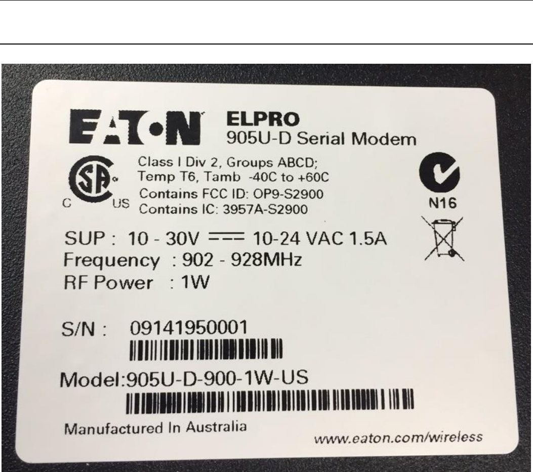
CHAPTER 9 - LABELLING
Sample Label