ELTA ADT406 ELT 406 MHz (Emergency Locator Transmitter) User Manual
ELTA ELT 406 MHz (Emergency Locator Transmitter)
ELTA >
Contents
- 1. ADT 406 AF AP users handbook
- 2. ADT 406 AP users handbook
ADT 406 AP users handbook

86(5¶6+$1'%22.
Documentation P/N: 03E61013 Rev B
Initial issue: Feb 15/03
Title Page
Apr 17/03
86(5¶6+$1'%22.
,1&/8',1*,167$//$7,210$18$/
$1'/2*%22.
(0(5*(1&</2&$72575$160,77(5
02'(/$'7$3
,17+(&263$66$56$76<67(0
Issued by
(/7$
)
14 Place Marcel Dassault
31702 BLAGNAC
France
www.elta.fr
SERIAL NUMBER LABEL

86(5¶6+$1'%22.
Page 1
Apr 17/03
LIST OF UPDATES
INSERTION INSERTION
UPDATE
No. ISSUE DATE BY
UPDATE
No. ISSUE DATE BY
A
B INITIAL
Feb 15/03
Apr 17/03 E.LABRIFFE
E.LABRIFFE

86(5¶6+$1'%22.
Page 2
BLANK
PAGE INTENTIONALLY LEFT BLANK

86(5¶6+$1'%22.
Page 3
Apr 17/03
LIST OF EFFECTIVE PAGES
CHAPTER/
SECTION PAGE
DATE
CHAPTER/
SECTION PAGE
DATE
TITLE PAGE
LISTE OF UPDATES
LIST OF EFFECTIVE PAGE
TABLE OF ILLUSTRATIONS
LEADING PARTICULARS
TABLE OF CONTENTS
1
2
3
4
5
6
7
8
9
10
11
12
13
14
15
16
17
18
19
20
21
22
23
24
25
26
27
28
29
30
31
32
33
34
Apr 17/03
Apr 17/03
BLANK
Apr 17/03
BLANK
Feb 15/03
BLANK
Feb 15/03
BLANK
Feb 15/03
BLANK
Feb 15/03
Feb 15/03
Feb 15/03
Apr 17/03
Apr 17/03
Apr 17/03
Apr 17/03
Apr 17/03
Feb 15/03
Apr 17/03
Feb 15/03
Feb 15/03
Feb 15/03
Feb 15/03
Feb 15/03
Apr 17/03
Feb 15/03
Apr 17/03
Apr 17/03
Apr 17/03
Apr 17/03
Feb 15/03
Feb 15/03
Apr 17/03
Appendix A
Appendix B
1
2
3
4
5
1
2
3
4
5
6
7
8
9
10
11
12
13
14
Feb 15/03
Feb 15/03
Feb 15/03
Feb 15/03
Feb 15/03
Feb 15/03
Feb 15/03
Feb 15/03
Feb 15/03
Feb 15/03
Feb 15/03
Feb 15/03
Feb 15/03
Feb 15/03
Feb 15/03
Feb 15/03
Feb 15/03
Feb 15/03
Feb 15/03

86(5¶6+$1'%22.
Page 4
BLANK
PAGE INTENTIONALLY LEFT BLANK

86(5¶6+$1'%22.
Page 5
Feb 15/03
TABLE OF ILLUSTRATIONS Page
Figure 1 : COSPAS/SARSAT - System Principle 12
Figure 2 : ELT ADT 406 AP Presentation 14
Figure 3 : ELT ADT 406 AP – Dimensions (Basic Configuration) 15
Figure 4 : Tolerances on the Axis for Installation of the ELT ADT 406 AP 22
Figure 5 : Installation of the ELT ADT 406 AP - Drilling Pattern Dimensions 24
Figure 6 : ELT ADT 406 AP Installation - Wiring Diagram 26
Figure 7 : ELT ADT 406 AP - Detailed Description 34

86(5¶6+$1'%22.
Page 6
BLANK
PAGE INTENTIONALLY LEFT BLANK

86(5¶6+$1'%22.
Page 7
Feb 15/03
LEADING PARTICULARS
&$87,21 7+,675$160,77(5,6$87+25,=(')2586(21/<'85,1*6,78$7,2162)*5$9(
$1',00,1(17'$1*(5
&$87,21 ,7,6,03(5$7,9(7+$7($&+%($&212:1(55(*,67(567+(,5%($&21&217$&7
(/7$25$33529('$*(17722%7$,17+(,1)250$7,215(/$7,9(727+,6
5(*,675$7,21
&$87,21 7+(%($&210867,03(5$7,9(/<%(352*5$00(':,7+7+(5(/(9$17
,'(17,),&$7,21$87+25,=('%<7+(/2&$/$,5:257+,1(66
&$87,21 21&(7+(%($&21+$6%((1352*5$00(',7,6*(1(5$/<$66,*1('72$1
$,5&5$)71$0($1','(17,),&$7,21,)7+,6%($&21,686('21$127+(5
$,5&5$)7,7:28/'+$9(72%(5(352*5$00('1(:1$0($1','(17,),&$7,21
&$87,21 %()25(,167$//,1*2586,1*7+,6(48,30(177+(9$/,',7<2)7+(,1)250$7,21
217+(%($&21/$%(/0867,03(5$7,9(/<%(&+(&.('

86(5¶6+$1'%22.
Page 8
BLANK
PAGE INTENTIONALLY LEFT BLANK

86(5¶6+$1'%22.
Page 9
Feb 15/03
TABLE OF CONTENTS
PAGE
1. INTRODUCTION TO THE COSPAS-SARSAT SYSTEM 11
A. The COSPAS-SARSAT system 11
B. System organization 11
C. The distress frequencies 13
D. ELTA and the COSPAS-SARSAT system 13
2. GENERAL DETAILS OF THE ELT ADT 406 AP 14
A. Purpose of the ELT ADT 406 AP 14
B. Characteristics 16
3. DESCRIPTION OF THE ELT ADT 406 AP AND OF THE AIRCRAFT COMPONENTS 18
A. General description 18
B. Detailed description 18
4. INSTALLATION OF THE ELT ADT 406 AP 22
A. General 22
B. Installation of the beacon on the aircraft 22
C. External antenna installation 25
D. Remote control unit installation 25
E. Installation and configuration of the beacon 27
5. UTILIZATION OF THE ELT ADT 406 AP 28
A. Automatic activation 28
B. Manual activation 28
C. Beacon shutdown 30
D. Beacon self-test 30
6. MAINTENANCE OF THE ELT ADT 406 AP 32
A. Beacon self-test 32
B. Maintenance periodicity table 32
C. Battery replacement 32
D. Battery discarding 33
E. Test to do at the time of a beacon return in workshop 33

86(5¶6+$1'%22.
Page 10
BLANK
PAGE INTENTIONALLY LEFT BLANK

86(5¶6+$1'%22.
Page 11
Feb 15/03
1. INTRODUCTION TO THE COSPAS-SARSAT SYSTEM
A. The COSPAS-SARSAT* system
The purpose of the COSPAS-SARSAT satellite system is to detect and locate all distress signals transmitted
by aeronautical, maritime or land-based beacons, for the search and rescue organizations.
This program is the result of an international collaboration between the United States, Canada and France
on the one hand (SARSAT project), and Russia on the other hand (COSPAS project). These two projects
are fully compatible.
Since the first results were obtained several countries have joined the program. Several other countries
have shown an interest and will soon be joining the COSPAS-SARSAT system partners.
ELTA in relation with CNES (French National Space Agency) has developed the complete range of products
required for COSPAS-SARSAT system operation.
Following an in-depth study phase, ELTA has arrived at highly conclusive technical results, and experimental
and operational use of the "ground" equipment have proven this equipment’s reliability and ease-of-use.
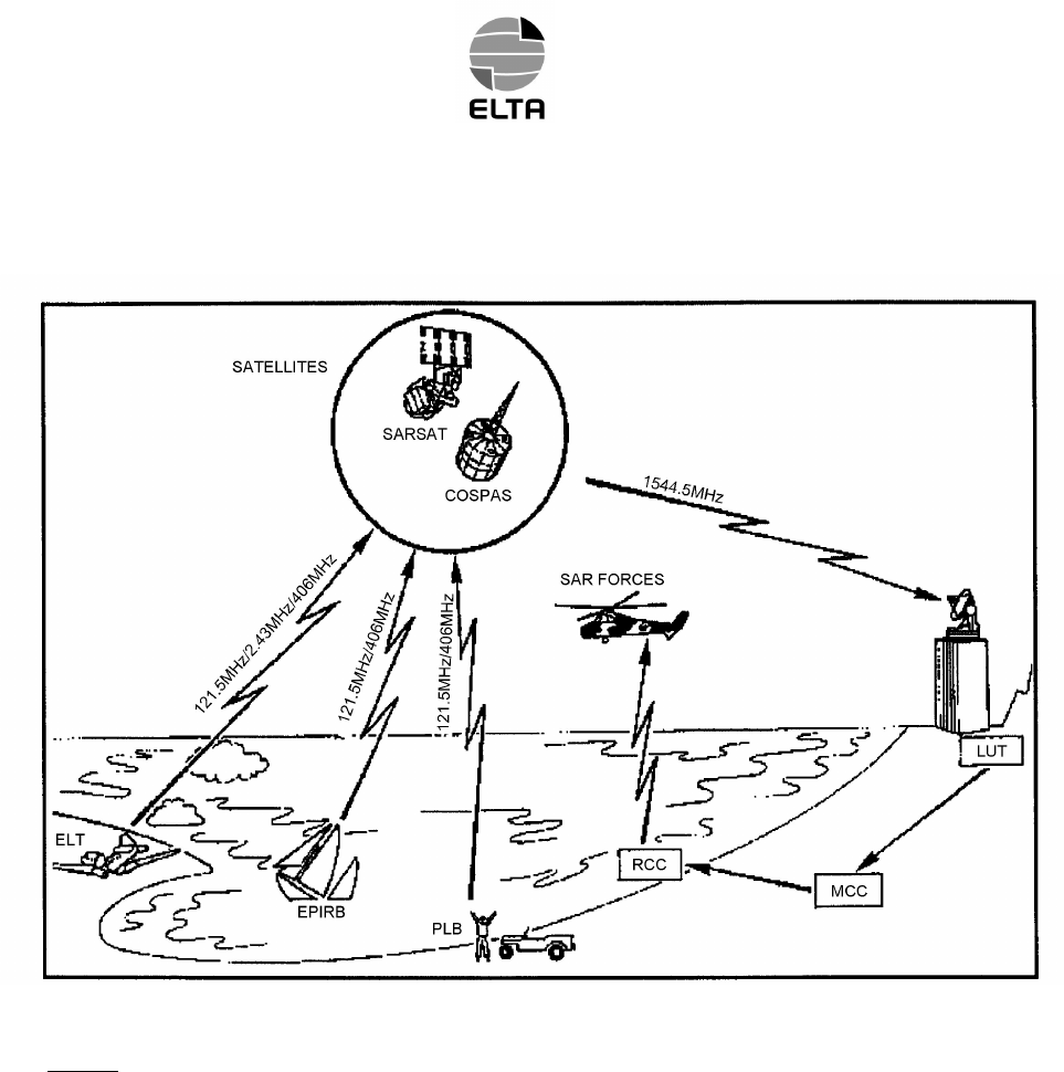
B. System organization (Ref. Fig. 1)
In the COSPAS-SARSAT system, space equipment is placed on board several satellites in low near-polar
orbit to capture transmissions from emergency transmitters and to retransmit these signals to specialized
ground stations called /ocal 8ser 7erminals (LUT). These ground stations determine the position of the
emergency transmitters and then retransmit the position data to the designated 0ission &ontrol &enters
(MCC). The MCCs in turn retransmit these data to the appropriate 5escue &oordination &enters (RCC) so
that they can start the search and rescue operations.
* COSPAS-SARSAT :
COSPAS = Kosmicheskaya Sistyema Poiska Avariynych Sudov
SARSAT = Search and Rescue Satellite-Aided Tracking
86(5¶6+$1'%22.
Page 12
Feb 15/03
Legend :
ELT : (mergency /ocator 7ransmitter
EPIRB : (mergency 3osition ,ndicating 5adio %eacon
PLB : 3ersonal /ocator %eacon
RCC : 5escue &oordination &enters
MCC : 0ission &ontrol &enters
LUT : /ocal 8ser 7erminals
COSPAS/SARSAT – System Principle
Figure 1

86(5¶6+$1'%22.
Page 13
Feb 15/03
C. The distress frequencies
There are several advantages to using the 406 MHz frequency :
– Worldwide coverage: locating is not only possible in real-time within a radius of 2,500 km around the
station, but also in global mode outside this zone since the satellites memorize the messages on the 406
MHz frequency. Location process uses Doppler effect.
– Locating accuracy: 2 km as opposed to 10 to 15 km in the 121.5 MHz or 243 MHz frequencies. It should
be noted however that the 406 MHz beacons also transmit 121.5 MHz and 243 MHz signals which enable
the final approach of the rescue teams in homing mode.
– Information reliability: the structure of the digital signal transmitted by these beacons makes it possible to
be sure that there is actually a distress situation, as well as to identify automatically the mobile in distress
which is vital for rescue operations.
– Unique identification: each beacon has it’s own identification information.
D. ELTA and the COSPAS-SARSAT system
(1)406 MHz distress beacons:
These beacons transmit to the satellites a digital message which identifies them and gives their position,
as well as a signal that facilitates the final approach of the rescue teams.
They are suitable for all types of use (maritime, aeronautical and land) and can, depending on the model,
be activated manually or automatically. They are designed to function in the most extreme conditions with a
high degree of reliability.
(2)Satellites low earth orbiting:
At least four satellites are permanently operational. Since their orbit is near-polar, in the worst case every
point on Earth is overflown every two hours.
In a ground station's visibility zone, the satellites directly transmit the messages captured in that zone, and
also any messages from the zones not covered that they have stored in memory.
(3)Geo-stationary satellites are now available in the system and offer faster detection capability (close to 5
minutes) but require a GPS receiver to supply location that is sent via C/S message.
(4)Ground reception stations:
The zone effectively covered (or visibility zone) is a circle with a radius of 2,500 km around the station.
These stations receive (via the satellites) and process, in real time, the messages from the beacons
activated in their visibility zone and, in batch mode, the messages from the 406 MHz beacons activated
outside that zone and memorized by the satellites.
Automatic processing of the 406 MHz digital messages allows the beacons to be located and the carrier
mobile to be identified.
86(5¶6+$1'%22.
Page 14
Apr 17/03
2. GENERAL DETAILS OF THE ELT ADT 406 AP
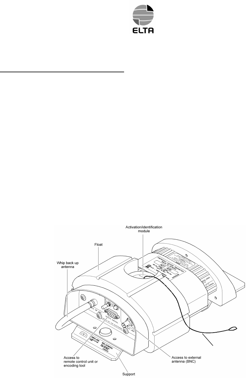
A. Purpose of the ELT ADT 406 AP (Ref. Fig. 2)
The ELT ADT 406 AP consists of a beacon that incorporates means of attachment.
The ELT ADT 406 AP is designed to transmit a digital distress signal to satellites that are part of the
COSPAS/SARSAT SYSTEM.
These satellites transmit the captured signal to the reception stations on the ground.
This signal is transmitted on the 406.028 MHz frequency and is used to precisely locate and identify the ELT
ADT 406 AP.
It also transmits a 121.5 MHz and 243 MHz signal to facilitate the final approach of the distress scene
(homing).
It can be triggered manually or automatically by means of an acceleration sensor (G.switch in accordance to
EUROCAE ED-62 standard).
This ELT meets the latest JAR OPS and ICAO recommendations.
Any encoding protocol defined by COSPAS/SARSAT can be used with ELT ADT 406 AP including country
code assignation.
ELT ADT 406 AP- Presentation
Figure 2
Metalic stap
86(5¶6+$1'%22.
Page 15
Apr 17/03
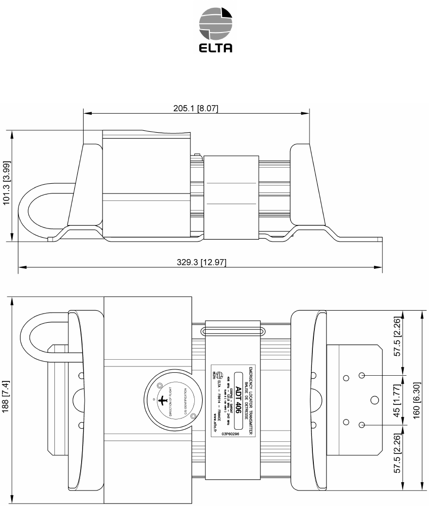
ELT ADT 406 AP - Overall Dimensions
(Without optional protecting cover)
Figure 3

86(5¶6+$1'%22.
Page 16
Apr 17/03
B. Characteristics (Ref. Fig. 3)
(1)Approvals
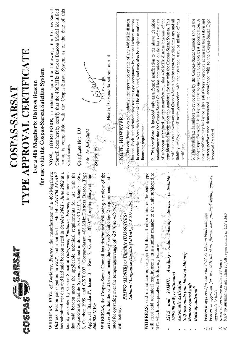
ADT 406 AP is COSPAS/SARSAT approved (TAC 131, dated July 2002)
ADT 406 AP meets EUROCAE ED62 standard
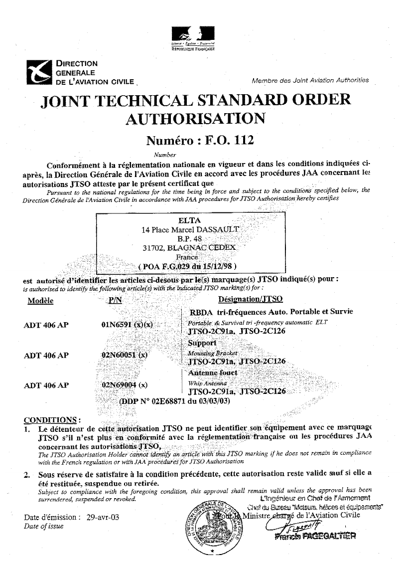
ADT 406 AP is JTSO 2C91a and JTSO 2C126 (JTSO N° F.O. 0112 dated April 29, 2003)
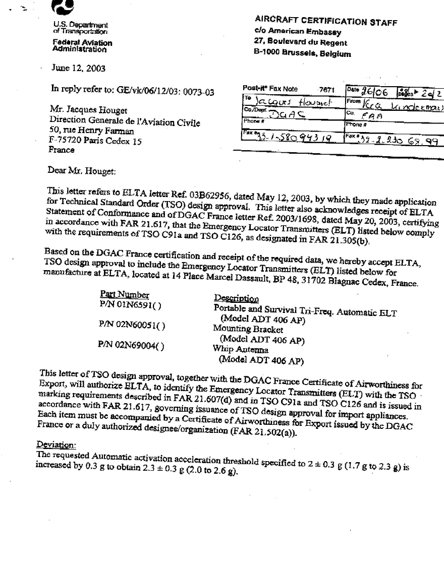
ADT 406 AP is TSO C91a and TSO C126 (TSO letter dated June 12, 2003)
(2)Physical characteristics
(a)Beacon with support
Height : 101.3 mm
Width : 188 mm
Length : 329.3 mm
Weight : 2.1 kg or 2.15 kg with the option of a protecting cover
(b)Beacon only
Height : 101.3 mm
Width : 188 mm
Length : 234 mm (without back up antenna)
Weight : 1.7 kg (with back up antenna)
Back up antenna length : 375 mm (deployed)
(3)General characteristics
(a)External antenna
– Omnidirectionnal three-frequency antenna 50Ω access,
– conform to COSPAS/SARSAT and EUROCAE ED-62 specifications.
(b)Power supply
High energy batteries (2 series-connected packs), activable for 5 years. Autonomy 24 hours on 406.028
MHz and greater than 60 hours at -20°C on 121.5&243 MHz.
– Voltage : 6 VDC,
– capacity : 10.5 A/h,
– ELTA type number :00E64191,
– lithium manganese dioxide (solid cathode),
– battery servicing kit available: 02N60052 kit for one ELT
02N60053 kit for 10 ELT

86(5¶6+$1'%22.
Page 17
Apr 17/03
(c)Radio-electrical characteristics
1 406 MHz satellite transmitter
– Frequency : 406.028 MHz,
– transmitter power : 5 W,
– modulation : "L" two-phase,
– transmission recurrence : 50 s,
– transmission duration : 440 or 520 ms.
2 Associated homing transmitter
– Frequency : 121.5 MHz/243 Mhz or 121.5 MHz (selectable),
– 121.5 MHz transmitter power : 140 mW,
– 243 MHz transmitter power : 140 mW,
– modulation : AM (3K20A3X type) from, 1600 Hz to 300 Hz,
up to four periods per second,
– antenna gain : > 1 dBi.
(d)Environment characteristics
– Operating temperatures : -20°C to +55°C,
– storage temperatures : -55°C to +85°C.
(e)Miscellaneous characteristics
– Automatic activation level in accordance with EUROCAE ED-62 (internal G-switch).
Activation direction is selectable (4 possibe directions),
– color : orange in conformity with the international distress signal,
– self-test : transmission of one burst modulated with inverted frame synchronization
and 5s transmission of 121.5 MHz ,
automation to off position (on remote control panel),
– any COSPAS/SARSAT protocol available,
. ELT S/N
. A/C operator designator and S/N
. A/C 24 bits address
. A/C nationality and registration marking (recommended)
. Test
– any country code available,
– can operate in short or long C/S message.
For long message, location data (from on board GPS as exemple) is received from A/C data bus
through an interface module, P/N 01N6593(x)
– C/S identification stored in a transferable module to ease maintenance on ELT,
– dual antenna access
Primary for external antenna and back up antenna in case of failure detection on primary access.

86(5¶6+$1'%22.
Page 18
Apr 17/03
3. DESCRIPTION OF THE ELT ADT 406 AP AND OF THE AIRCRAFT COMPONENTS
A. General description
(1)Introduction
This beacon from the ADT406 family derives from the ADT 406 AF/AP model. Consequently, this beacon
features the functional capabilities of the AF/AP besides its flotation gear, the attachment interface and its
flexible antenna entirely compatible with Cospat/Sarsat.
(2)The ELT ADT 406 essentially consists of :
– an ADT 406 AP beacon transmitter
– a whip antenna,
– labels,
– an activation / identification module,
– a support.
(3)The ELT ADT 406 AP basic aircraft components consists of :
– a remote control unit,
– an external antenna.
Note : this beacon can be used in survival mode without these elements.
B. Detailed description (Ref. Fig. 7)
(1)The ADT 406 AP beacon
The ADT 406 AP beacon mainly consists of :
– a whip antenna,
– a power supply module,
– an electronic assembly,
– a mechanical assembly,
– a float.
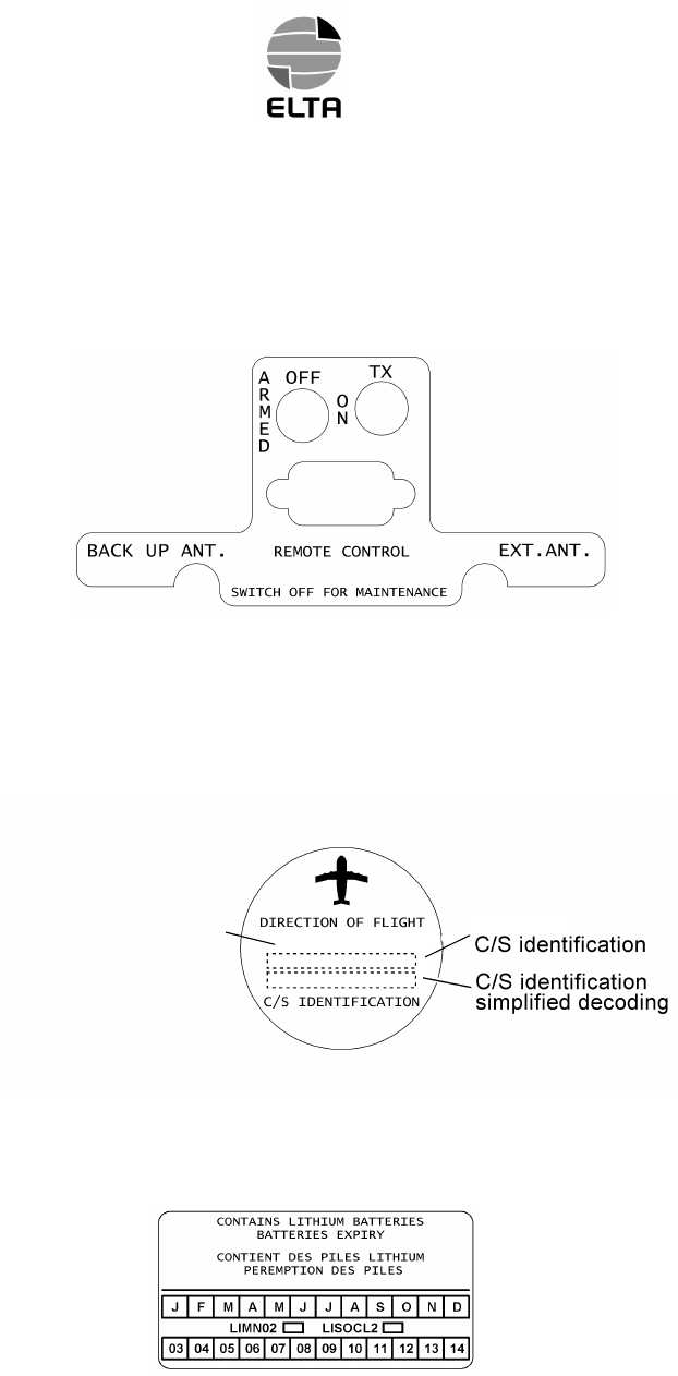
The front face of the electronic assy is equipped with the following components :
– a REMOTE CONTROL electrical high density 15 pins female connector (10) for connecting up to the
aircraft remote control panel or programming tools,
– a BACK UP WHIP ANT. TNC female connector (13) for connecting up the antenna,
– an EXT. ANT. BNC female connector (9) for connecting up the external antenna,
– an ARMED/OFF/ON lockable toggle switch (12) for activating the beacon,
– a TX indicator light (11) indicating beacon activation (real distress and self-test).
86(5¶6+$1'%22.
Page 19
Feb 15/03
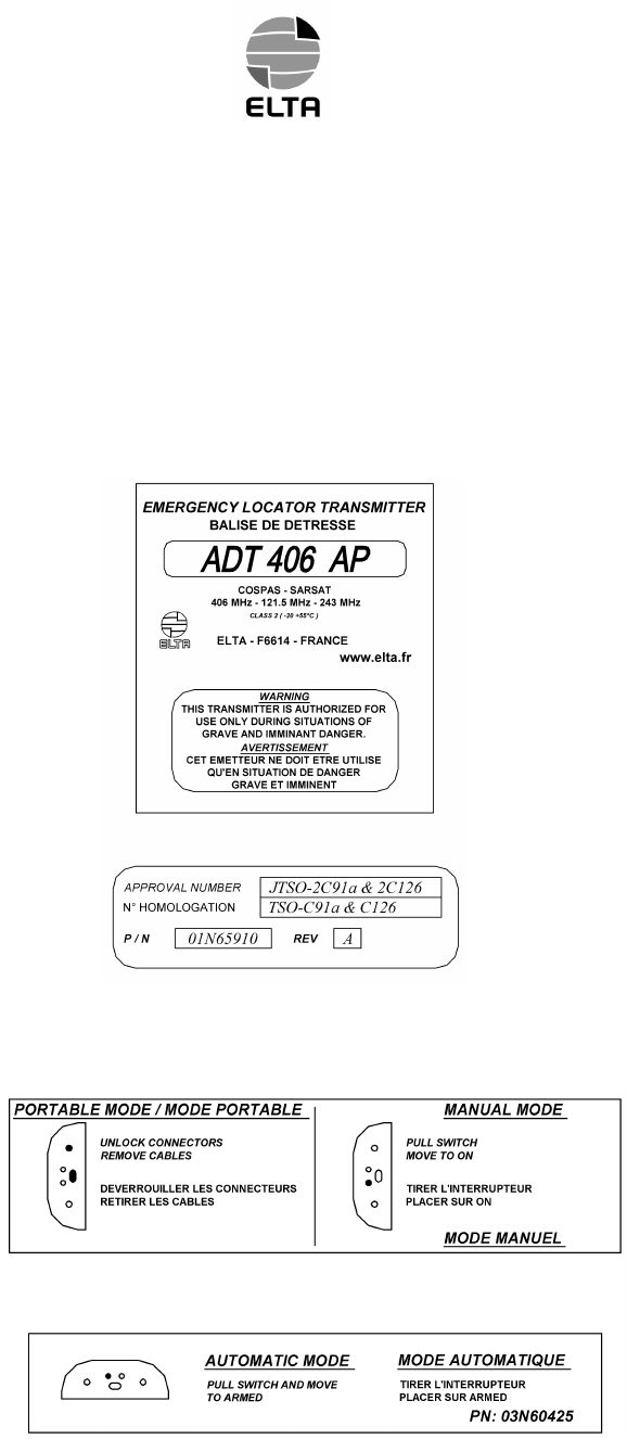
(2)The labels
(a)Identification label
This label indicates :
– beacon name, manufacturer details,
– the condition in which the beacon may be used (warning),
– approval number, identification, part number, service bulletin, serial number and conditions on the
use of the beacon.
(b)Connectors use label
This label gives indication on the electronic front face connectors use.
86(5¶6+$1'%22.
Page 20
Apr 17/03
(c)Connectors location label
This label indicates the location of the connectors on the front face of the electronic assy.
(d)Identification label
This label indicates the axis according to which the ELT ADT 406 AP must be installed on the aircraft
(see paragraph. 4.B.) for automatic activation (G-switch).
It is fixed to the activation / identification module.
(e)Batteries label
This label indicates the batteries expiry date (next battery servicing).
Homing pwr xx dBm
Homing power
selection
Official 15 Hex.

86(5¶6+$1'%22.
Page 21
Feb 15/03
ELT ADT 406 AP aircraft components
(f)Remote control unit
The remote control unit integrated in the aircraft cockpit consists of :
– a RESET/TEST pushbutton,
– an ELT ON indicator light,
– a two-position ON/ARMED switch with safety cover (flip guard). The safety cover forces the switch to
ARMED position. This switch must always remain in this position, except in the case of manual
distress triggering.
The beacon is integrated in the aircraft as far aft as possible and so it must be connected to the remote
control unit. This remote control unit enables beacon operation to be forced to ON, to be tested (TEST)
or shutdown and restore in standby or ARMED mode (RESET) in the event of an untimely triggering of
the ELT, from the aircraft cockpit.
(g)External antenna
An external antenna is recommended to be installed on the fuselage of the aircraft to maximize
transmission of the distress signal to the satellites.
The cable lenght should remain as short as possible in order to RF keep losses as close as possible to
0.5 to 1 dB at each frequencies (121.5/243/406.028 MHz).
86(5¶6+$1'%22.
Page 22
Feb 15/03
4. INSTALLATION OF THE ELT ADT 406 AP
A. General
System security and reliability obviously depends on the standard of installation.
In order to ensure installation of the highest standard, the installation operations must be :
– performed in conformity with this document,
– performed in compliance with the current regulations,
– performed by qualified personnel,
– performed so that :
. the aircraft's structural integrity is not affected,
. it will not hinder the pilot in normal position,
. it will not cause any damage in the event of an accident,
. it will not prevent or modify operation of the other safety systems.
If in doubt, contact the aircraft manufacturer or its representative,
– inspected by representative authority.
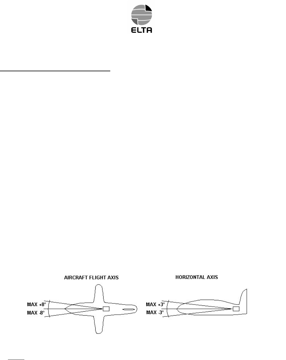
B. Installation of the beacon on the aircraft (Ref. Fig. 4)
In the case of use in automatic mode, the beacon shall be installed in the rear of the aircraft in order to
maximize the probability of ELT survival in case of crash. However, it can be installed in another position in
survival mode.
The activation / identification module DIRECTION OF FLIGHT must be parallel with the aircraft flight axis as
indicated by the beacon's label. The activation / identification module direction and the A/C forward/aft
directions must be respected to ensure correct acceleration sensor (G.switch) operation (See Fig. 4).
NOTE : An angle of up to ± 8° from the aircraft flight axis could be allowed.
An angle of up to ± 3° from the aircraft horizontal axis could be allowed.
Tolerances on the Axis for Installation of the ELT ADT 406 AP
Figure 4
86(5¶6+$1'%22.
Page 23
Feb 15/03
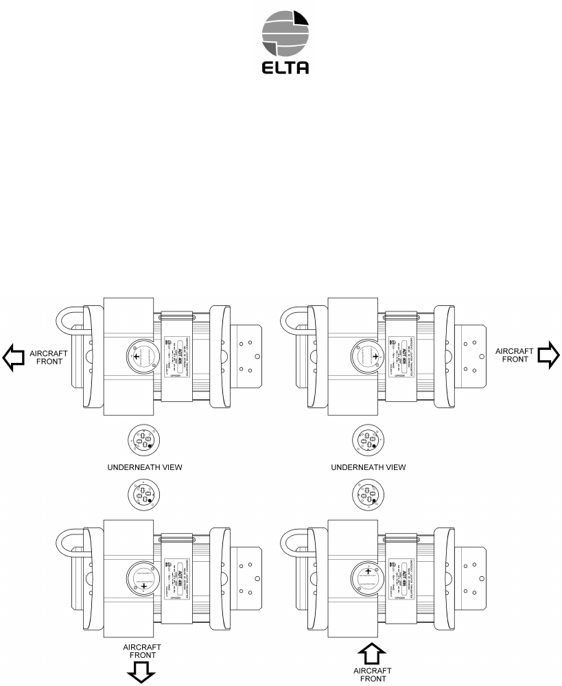
The beacon can be installed in any position (normal, upside down, right side, left side) with respect with the
G-Switch activation direction stated on figure 4.
The activation / identification assy of the beacon can be installed in four positions. Three alignment pins on
the beacon board allow to set it in the required position. A cap is installed in one of the four holes of the
activation / identification assy who is unused.
7KLVFDSVKDOOEHDVVLJQHGXSRQWKHLQLWLDOLQVWDOODWLRQDQGZLOONHHSWKLVSRVLWLRQLQPHPRU\IRU
IXUWKHUEHDFRQUHSODFHPHQW
Unstowed objects must be not able to impact the beacon.
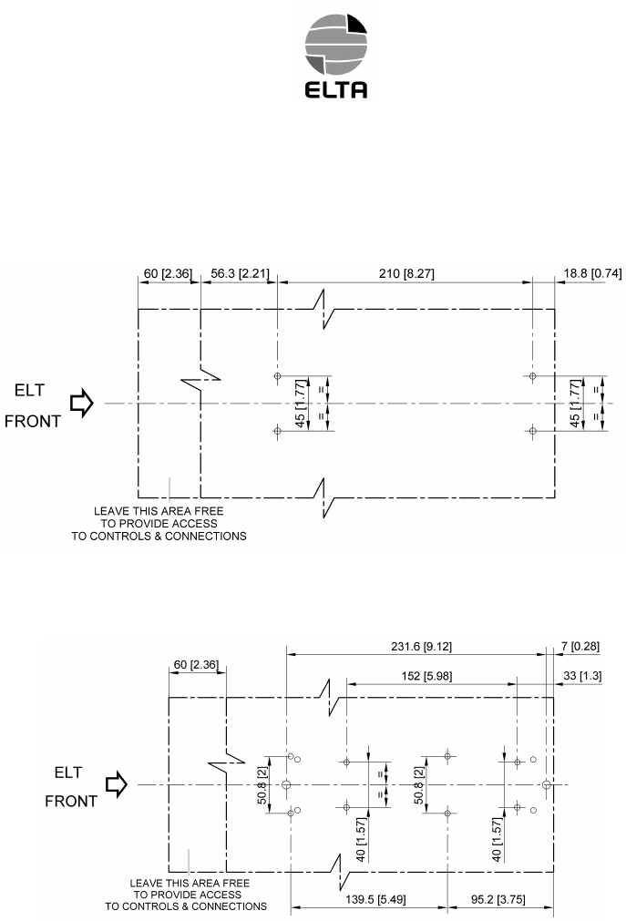
Attach the beacon to the fuselage of the aircraft by means of four M4 bolts. Four 5 mm diameter holes at the
corners of a 210 mm x 45 mm rectangle are drilled in the beacon. Particular care must be taken with this
attachment. Standard industry means must be used to lock the screws. Use flat washer in order to avoid
paint damage.
The attachment points are similar to those of the ADT 406 AF/AP beacon.
86(5¶6+$1'%22.
Page 24
Feb 15/03
The figure 5 shows the drilling pattern dimensions and determine the required area to access to the beacon
controls and connectors.
ELTA Recommendation
Optional for Other Beacon Retrofit
Installation of the ELT ADT 406 AP - Drilling Pattern Dimensions
Figure 5

86(5¶6+$1'%22.
Page 25
Feb 15/03
C. External antenna installation
This antenna should be approved by ELTA.
ELTA recommend to use P/N 25988 (antenna model 2624-82 manufactured by CHELTON)
The external antenna must be installed on the upper part of the fuselage, as far aft as possible.
Particular care must be taken with this attachment. Standart industry means must be used to lock the
screws.
The contact surface should be reinforced to prevent the antenna from tearing away at high speeds.
The cable used shall be of a high quality with very low losses.
RG 142 cable type is recommended with a length lower than 2 meters to keep losses close to 0.5 dB.
Connect the connector to the antenna and to the EXT. ANT. access on ELT, and install the coaxial cable.
This cable must be fixed to rigid aircraft structure all along its routing, and it should be as short as possible
to avoid Radio Frequency losses and/or cable destruction in case of crash.
D. Remote control unit installation
The ELT ADT 406 AP can be remotely controlled by using a remote control panel installed in the cockpit of
the aircraft.
The maximum length of this link is 200 meters and requires no grounded cable. The link requires 4 wires.
86(5¶6+$1'%22.
Page 26
Apr 17/03
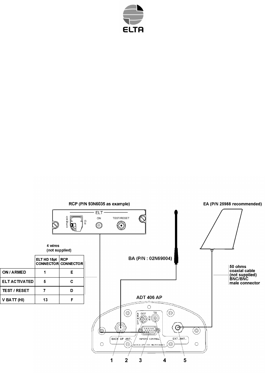
The following simplified diagram shows the wiring between the ELT ADT 406 AP and its peripherals :
– The Remote Control Panel (in cockpit) identified as "RCP",
– the external antenna noted as "EA",
– the whip antenna noted as "BA".
The EA is connected to the ELT ADT 406 AP BNC female connector (5).
The BA is connected to the ELT ADT 406 AP TNC female connector (1).
The RCP is connected to the ELT ADT 406 AP high density 15 pins female connector (3).
ELTA recommend to use P/N 16243 for RCP connector and P/N 231 plus 232 for ELT.
A three position guarded switch (2) controls the ELT ADT 406 AP.
A red indicator (4) displays the ELT ADT 406 AP state.
ADT 406 AP Beacon Installation
Figure 6

86(5¶6+$1'%22.
Page 27
Feb 15/03
E. Installation and configuration of the beacon (Ref. Fig. 5)
(1)Installation in automatic mode
&$87,2172%(23(5$7,21$/7+(%($&216+$//%(,1$50('326,7,2121&(,7+$6
%((1&255(&7/<,167$//('
Connect the antenna cable to the EXT. ANT. connector.
Switch the Remote Control ON/ARMED lockable toggle switch to "ARMED" on remote control panel.
Connect the remote control unit cable to the REMOTE CONTROL connector on ELT and lock it.
Connect the remote control unit cable rear of the remote control panel and lock it.
Switch the Beacon ARMED/OFF/ON lockable toggle switch to ARMED (pull and slide), the system is ready
for use.
Note : the beacon can be used in automatic mode with neither RCP nor external antenna.
&$87,21$66221$67+(%($&21,6,1$50(',7&$1%($8720$7,&$//<$&7,9$7('%<
7+(,17(51$/*6:,7&+
(2)Installation in survival mode
Connect the whip back up antenna to ELT.
The switch shall be on OFF.

86(5¶6+$1'%22.
Page 28
Apr 17/03
5. UTILIZATION OF THE ELT ADT 406 AP (Ref. Fig. 7)
&$87,21,17+((9(172)817,0(/<%($&21$&7,9$7,216+87'2:17+(%($&21$1'
,1)2507+(&/26(676($5&+$1'5(6&8(6$525$,53257&21752/72:(5
,00(',$7(/<
The ELT ADT 406 can be activated in two modes :
– automatic when the acceleration sensor is triggered,
– manual.
A. Automatic activation
The acceleration sensor has detected an impact sufficient to trigger it. The indicator light (11) and the aural
indicator indicate beacon activation.
If the aircraft has to be evacuated, refer paragraph B.(2) second case. Otherwise do not do anything and
leave the beacon in operation until the rescue team arrives.
B. Manual activation
There are two cases in which a distress signal may be triggered manually :
– the acceleration sensor (G.switch) has not been triggered but a distress signal must be sent (injured
passengers, aircraft out of operation ...),
– the aircraft is on the ground and must be evacuated.
(1)First case, from the Remote Control
Raise the safety cover (guard) on the remote control unit and place the switch in the ON position (lever
upwards).
An automatic self-test sequence is performed.
Then the indicator light (11) and the aural indicator indicate beacon activation. This signal is permanently
displayed on the Remote Control LED.
Do not do anything and leave the beacon in operation until the rescue team arrives.
(2)Second case, from the beacon
Place the beacon switch (12) in the ON position (pull and slide).
An automatic self-test sequence is performed.
Then the beacon enter in a waiting condition for about 30s. This state is displayed by flashing on indicator
light (10) 1.75 s ON, 0.25 s OFF. This delay will avoid unwanted activation (false manoeuvre).
Then the indicator light (11) and the aural indicator indicate beacon activation. The actual distress signal is
transmitted. This state is displayed by flashing on indicator light : 0.5 s ON, 0.5 s OFF.
86(5¶6+$1'%22.
Page 29
Apr 30/03
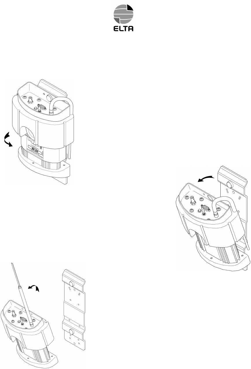
If the aircraft has to be evacuated, Follow the instructions :
- unfasten the strap (and the cable if relevant),
- remove the beacon from its bracket,
pull firmly to brake the retaining metallic
strap (14, Ref. Fig. 7).
- extend the antenna and take the beacon with you.

86(5¶6+$1'%22.
Page 30
Apr 17/03
C. Beacon shutdown
In the event of a false manoeuvre or untimely operation, shutdown the beacon.
The beacon is shutdown by pressing the RESET/TEST pushbutton on the remote control unit. This control is
not active during the self test sequence or if the ON/ARMED switch is in ON position.
NOTE : Stopping distress signal transmission by means of the remote control unit does not switch the
beacon OFF. It is restored in ARMED mode.
Acknowledgment of the control is displayed by 2 short blink on LED and buzzer.
&$87,217+(%($&210867%(6+87'2:1%()25($1<0$,17(1$1&(23(5$7,216$5(
3(5)250('
7+(%($&210867%(&203/(7(/<6+87'2:1%()25(,7,65(029('$1',76
$50('2))2172**/(6:,7&+6+$//%(,12))326,7,21
D. Beacon self-test
&$87,217+(6(/)7(676+$//%(3(5)250(':,7+,17+(),567012)$1<+285
%(&$86(7+((/7,66(1',1*0+=6,*1$/)256'85,1*7+,6352&(66
/,0,7$7,212))$/6($/(57
The ELT ADT 406 AP is designed to perform a self-test, from the remote control unit, or as soon as the
beacon is started up manually.
Actual test transmission on 121.5 MHz for 5 s can be listen on any VHF receiver.
(1)Self-test on the beacon
&$87,217+,66(/)7(67352&(666+$//127%(,17(5837('
,)7+,6352&(66,6127&203/(7()25$1<5($6213(5)250$1(:
&203/(7(6(/)7(67
Note : in case of use in survival mode without external antenna, the self-test will indicate an antenna
failure, but the beacon will transmit normally on its emergency antenna.
Place the beacon’s ARMED/OFF/ON toggle switch (12) in ON position.
After two short blinks and a delay of 3 s, check that the indicator light (11) comes ON and the beacon’s
buzzer sounds during 6s.
After a brief blink the self-test report is display :
– 10 s permanent illumination of the indicator light (11) for correct operation,
– 10 s blinking condition of the indicator light (11) for failure detection.
Blinking rate indicates the failure source detection as follow :
. 125 ms ON, 125 ms OFF (Frequency 4 Hz), ELT Check Sum failure (software problem)
. 250 ms ON, 250 ms OFF (Frequency 2 Hz), ELT power failure (UHF and/or VHF)
. 500 ms ON, 500 ms OFF (Frequency 1 Hz), Ext. Antenna connection failure or signal
identification missing.

86(5¶6+$1'%22.
Page 31
Apr 17/03
Then the beacon enter in a waiting condition for 30 s (rate : 1.75s ON; 0.25s OFF).
During this state return the switch (12) to ARMED position.
&$87,2123(5$7256+$//6:,7&+2))25$50('7+((/7:,7+,16$)7(56(/)7(67
5(325772$92,'5($/',675(6675$160,66,21
(2)Self-test by means of the remote control unit
The beacon’s ARMED/OFF/ON toggle switch (12) must be in ARMED position.
The Remote Control ARMED/ON must be in ARMED position.
Press the RESET/TEST pushbutton until the two acknowlegment blink on LED.
Then, after a delay of approximately 6 second, the self test is displayed on the Remote Control Unit LED.
– 10 s permanent illumination for correct operation,
– 10 s blinking condition for failure detection.
Blinking rate indicates the failure source detection as follow :
. 125 ms ON, 125 ms OFF (Frequency 4 Hz), ELT Check Sum failure (software problem)
. 250 ms ON, 250 ms OFF (Frequency 2 Hz), ELT power failure (UHF and/or VHF)
. 500 ms ON, 500 ms OFF (Frequency 1 Hz), Ext. Antenna connection failure or signal
identification missing.
NOTE : On the beacon, after the two short blinks, the indicator light (11) comes ON and the buzzer sounds
during 6 seconds. This is the self-test process. Then the self-test report is indicated as it is done for the Remote
Control Unit LED.
&$87,217+((/76+$//%(,1$50('326,7,21,)1275(027(&21752/:,//127
23(5$7(7(675(6(721
86(5¶6+$1'%22.
Page 32
Feb 15/03
6. MAINTENANCE OF THE ELT ADT 406 AP
A. Beacon self-test
The manufacturer recommends that a beacon self-test should be performed regularly. The highest rate is
one per day. Normally this task is added to other periodic maintenance task such a “A” check. In all events
the user must comply with the applicable regulations in the country concerned governing the self-test period.
The self-test must only be performed when the order to do so is given or by the competent authorities.
A higher rate of self-test will reduce the 5 years battery servicing.
&$87,217+(6(/)7(67352&('85(3$5$*5$3+'0867%(5(63(&7('72$92,'
817,0(/<%($&21$&7,9$7,21
B. Maintenance periodicity table
Periodicity Operations Operator
5 years Replacement of batteries ELTA or approved agent/airline
5 years General overhaul in specialized
workshop ELTA or approved agent/airline
C. Batteries replacement
&$87,217+(%$77(5<3$&.6+$//%($33529('%<(/7$,)27+(53$&.$5(86('(/7$
:,//&$1&(/:$55$17<$1':,//5()86($1<5(63216,%,/,7<217+(
352'8&723(5$7,210,6)81&7,21
&$87,217+(%$77(5,(686('&$1127%(5(&+$5*(''212775<7223(125
5(&+$5*(7+(0
Next battery servicing date is indicated on a label stuck on the back face of ADT 406 AP.
The old batteries must be replaced with new batteries of a model approved by ELTA P/N 02N60052 (battery
servicing for one ELT) or 02N60053 (battery servicing for ten ELTs).
ELTA recommends that the ELT ADT 406 AP should undergo a general overhaul on its test and
programming bench at this occasion.
Refer to CMM 25-60-10 for detail of operation.

86(5¶6+$1'%22.
Page 33
Feb 15/03
D. Batteries discarding
The batteries must be discarded in compliance with the applicable regulations in the country concerned.
NOTE : The type of battery used is not dangerous for the environment provided that it is completely
discharged.
Contact ELTA for getting additional discarding information.
E. Test to do at the time of a beacon return in workshop
Perfoms the following tests described in CMM 25-60-10 :
– visual check,
– test of acceleration sensor automatic triggering,
– functional test of ADT 406 AP beacon,
– RF test on the operational frequencies 121.5 – 243 – 406 MHz.
86(5¶6+$1'%22.
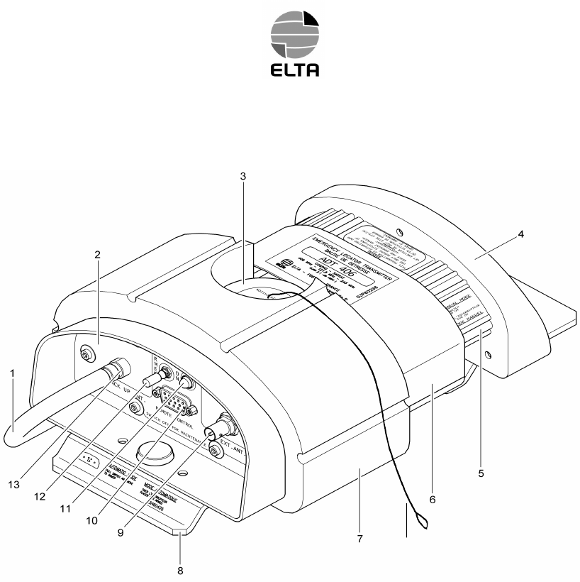
Page 34
Apr 17/03
1 – BACK UP ANTENNA (BASIC CONFIGURATION)
2 – FRONT FACE
3 – ACTIVATION/IDENT ASSY
4 – BACK FACE
5 – MACHINED SECTION
6 – STRAP
7 – FLOAT
8 – SUPPORT
9 – EXT. ANT. BNC CONNECTOR (FEMALE)
10 – REMOTE CONTROL CONNECTOR(FEMALE HD 15 PINS)
11 – TX LED
12 – ARMED/OFF/ON TOGGLE AND GUARDED SWITCH
13 – BACK UP ANT. TNC CONNECTOR (FEMALE)
14 – METALIC STRAP.
ELT ADT 406 AP – Detailed Description
Figure 7
14
Appendix A page 1
Feb 15/03
COSPAS-SARSAT
TYPE APPROVAL CERTIFICATE
Appendix A page 2
Feb 15/03
JTSO 2C91a AND JTSO 2C126
APPROVAL
Appendix A page 3
Feb 15/03
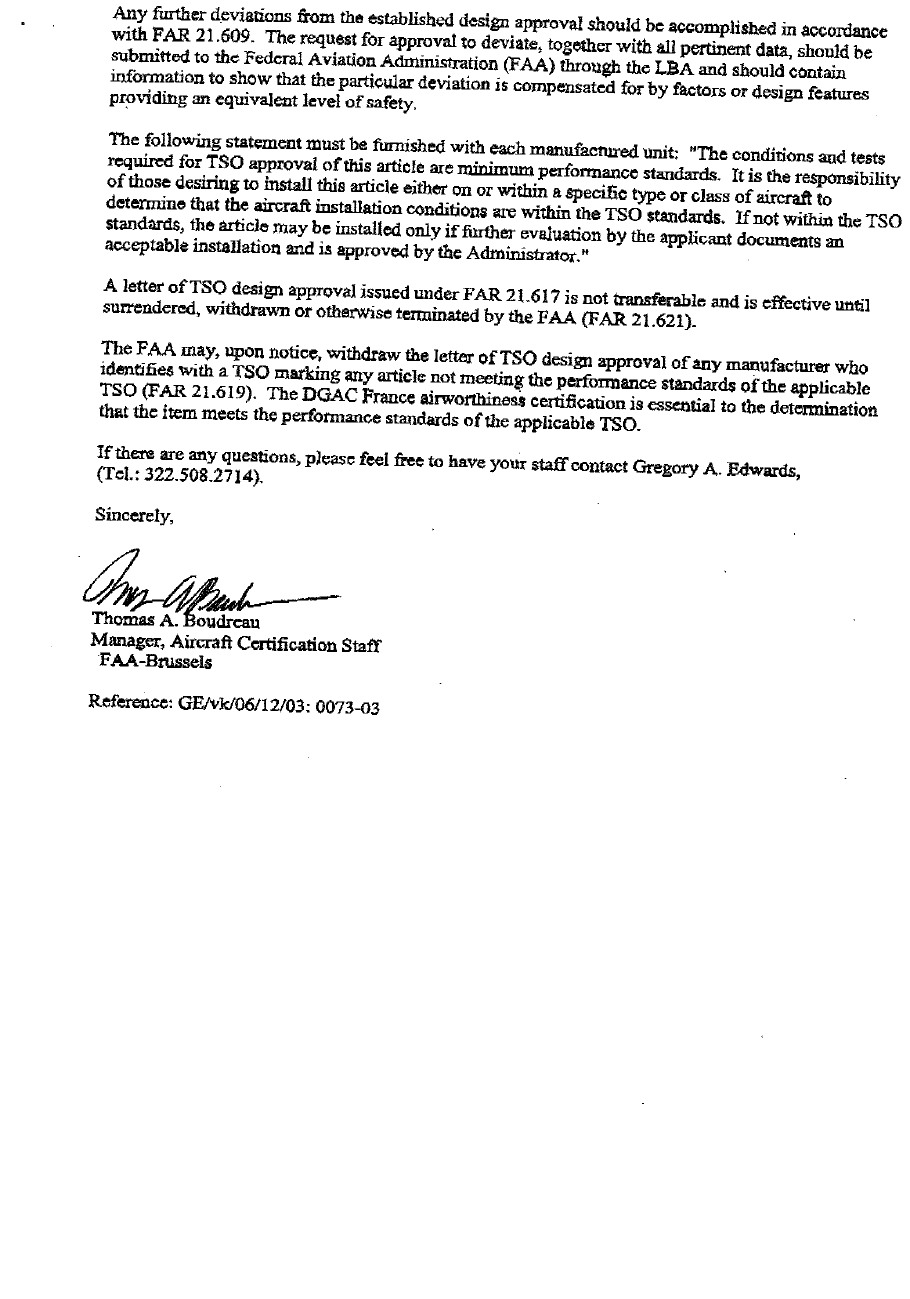
TSO C91a AND TSO C126
APPROVAL
Appendix A page 4
Feb 15/03
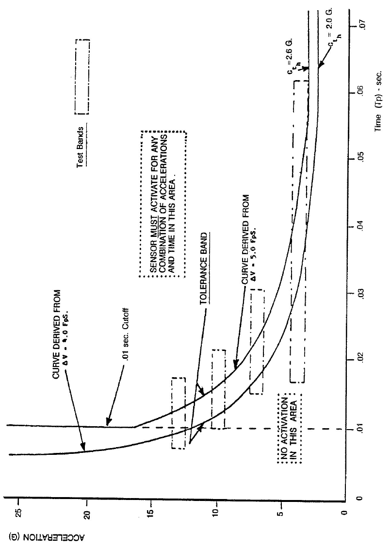
Appendix A page 5
Feb 15/03
Crash Sensor Response Curve
/2*%22.
Appendix B page 1
Feb 15/03
FACTORY SETTING
NEXT BATTERY SERVICING ……../……………. (MM/YYYY)
/2*%22.
Appendix B page 2
Feb 15/03
FACTORY SETTING

/2*%22.
Appendix B page 3
Feb 15/03
ENCODING UPDATE FORM
REGISTRATION COUNTRY: ELT SERIAL NUMBER:
PROTOCOL: ELT S/N A/C OP-DESIGNATOR + S/N
A/C 24 Bit Address A/C REG. MARK TEST
C/S 15 HEX:
SIMPLIFIED DEC:
A/C MSN: A/C OR A/P TYPE: FINAL OPERATOR:
CONTACT (PHONE, email…):
ISSUED BY:
DATE: ……/……/………… (MM/DD/YYYY)
SIGNATURE AND STAMP:
NOTE : Attach the encoding update sheet issued from the ELTA encoding tool.
REGISTRATION COUNTRY: ELT SERIAL NUMBER:
PROTOCOL: ELT S/N A/C OP-DESIGNATOR + S/N
A/C 24 Bit Address A/C REG. MARK TEST
C/S 15 HEX:
SIMPLIFIED DEC:
A/C MSN: A/C OR A/P TYPE: FINAL OPERATOR:
CONTACT (PHONE, email…):
ISSUED BY:
DATE: ……/…… /…… …… (MM/DD/YYYY)
SIGNATURE AND STAMP:
NOTE : Attach the encoding update sheet issued from the ELTA encoding tool.

/2*%22.
Appendix B page 4
Feb 15/03
ENCODING UPDATE FORM
REGISTRATION COUNTRY: ELT SERIAL NUMBER:
PROTOCOL: ELT S/N A/C OP-DESIGNATOR + S/N
A/C 24 Bit Address A/C REG. MARK TEST
C/S 15 HEX:
SIMPLIFIED DEC:
A/C MSN: A/C OR A/P TYPE: FINAL OPERATOR:
CONTACT (PHONE, email…):
ISSUED BY:
DATE: ……/…… /…… …… (MM/DD/YYYY)
SIGNATURE AND STAMP:
NOTE : Attach the encoding update sheet issued from the ELTA encoding tool.

/2*%22.
Appendix B page 5
Feb 15/03
ENCODING UPDATE FORM
REGISTRATION COUNTRY: ELT SERIAL NUMBER:
PROTOCOL: ELT S/N A/C OP-DESIGNATOR + S/N
A/C 24 Bit Address A/C REG. MARK TEST
C/S 15 HEX:
SIMPLIFIED DEC:
A/C MSN: A/C OR A/P TYPE: FINAL OPERATOR:
CONTACT (PHONE, email…):
ISSUED BY:
DATE: ……/…… /…… …… (MM/DD/YYYY)
SIGNATURE AND STAMP:
NOTE : Attach the encoding update sheet issued from the ELTA encoding tool.
REGISTRATION COUNTRY: ELT SERIAL NUMBER:
PROTOCOL: ELT S/N A/C OP-DESIGNATOR + S/N
A/C 24 Bit Address A/C REG. MARK TEST
C/S 15 HEX:
SIMPLIFIED DEC:
A/C MSN: A/C OR A/P TYPE: FINAL OPERATOR:
CONTACT (PHONE, email…):
ISSUED BY:
DATE: ……/…… /…… …… (MM/DD/YYYY)
SIGNATURE AND STAMP:
NOTE : Attach the encoding update sheet issued from the ELTA encoding tool.

/2*%22.
Appendix B page 6
Feb 15/03
ENCODING UPDATE FORM
REGISTRATION COUNTRY: ELT SERIAL NUMBER:
PROTOCOL: ELT S/N A/C OP-DESIGNATOR + S/N
A/C 24 Bit Address A/C REG. MARK TEST
C/S 15 HEX:
SIMPLIFIED DEC:
A/C MSN: A/C OR A/P TYPE: FINAL OPERATOR:
CONTACT (PHONE, email…):
ISSUED BY:
DATE: ……/…… /…… …… (MM/DD/YYYY)
SIGNATURE AND STAMP:
NOTE : Attach the encoding update sheet issued from the ELTA encoding tool.
REGISTRATION COUNTRY: ELT SERIAL NUMBER:
PROTOCOL: ELT S/N A/C OP-DESIGNATOR + S/N
A/C 24 Bit Address A/C REG. MARK TEST
C/S 15 HEX:
SIMPLIFIED DEC:
A/C MSN: A/C OR A/P TYPE: FINAL OPERATOR:
CONTACT (PHONE, email…):
ISSUED BY:
DATE: ……/…… /…… …… (MM/DD/YYYY)
SIGNATURE AND STAMP:
NOTE : Attach the encoding update sheet issued from the ELTA encoding tool.

/2*%22.
Appendix B page 7
Feb 15/03
ENCODING UPDATE FORM
REGISTRATION COUNTRY: ELT SERIAL NUMBER:
PROTOCOL: ELT S/N A/C OP-DESIGNATOR + S/N
A/C 24 Bit Address A/C REG. MARK TEST
C/S 15 HEX:
SIMPLIFIED DEC:
A/C MSN: A/C OR A/P TYPE: FINAL OPERATOR:
CONTACT (PHONE, email…):
ISSUED BY:
DATE: ……/…… /…… …… (MM/DD/YYYY)
SIGNATURE AND STAMP:
NOTE : Attach the encoding update sheet issued from the ELTA encoding tool.
REGISTRATION COUNTRY: ELT SERIAL NUMBER:
PROTOCOL: ELT S/N A/C OP-DESIGNATOR + S/N
A/C 24 Bit Address A/C REG. MARK TEST
C/S 15 HEX:
SIMPLIFIED DEC:
A/C MSN: A/C OR A/P TYPE: FINAL OPERATOR:
CONTACT (PHONE, email…):
ISSUED BY:
DATE: ……/…… /…… …… (MM/DD/YYYY)
SIGNATURE AND STAMP:
NOTE : Attach the encoding update sheet issued from the ELTA encoding tool.

/2*%22.
Appendix B page 8
Feb 15/03
ENCODING UPDATE FORM
REGISTRATION COUNTRY: ELT SERIAL NUMBER:
PROTOCOL: ELT S/N A/C OP-DESIGNATOR + S/N
A/C 24 Bit Address A/C REG. MARK TEST
C/S 15 HEX:
SIMPLIFIED DEC:
A/C MSN: A/C OR A/P TYPE: FINAL OPERATOR:
CONTACT (PHONE, email…):
ISSUED BY:
DATE: ……/…… /…… …… (MM/DD/YYYY)
SIGNATURE AND STAMP:
NOTE : Attach the encoding update sheet issued from the ELTA encoding tool.
REGISTRATION COUNTRY: ELT SERIAL NUMBER:
PROTOCOL: ELT S/N A/C OP-DESIGNATOR + S/N
A/C 24 Bit Address A/C REG. MARK TEST
C/S 15 HEX:
SIMPLIFIED DEC:
A/C MSN: A/C OR A/P TYPE: FINAL OPERATOR:
CONTACT (PHONE, email…):
ISSUED BY:
DATE: ……/…… /…… …… (MM/DD/YYYY)
SIGNATURE AND STAMP:
NOTE : Attach the encoding update sheet issued from the ELTA encoding tool.

/2*%22.
Appendix B page 9
Feb 15/03
MAINTENANCE TASKS
FINAL OPERATOR:
TYPE OF MAINTENANCE: BATTERY SERVICING INSPECTION REPAIR
RF TEST
TASK DESCRIPTION:
NEXT BATTERY SERVICING: ……/………… (MM/YYYY)
DATE: ……/…… /…… …… (MM/DD/YYYY)
REPAIR STATION:
SIGNATURE AND STAMP:
NOTE : Attach the RF test sheet issued from the ELTA test tool.
FINAL OPERATOR:
TYPE OF MAINTENANCE: BATTERY SERVICING INSPECTION REPAIR
RF TEST
TASK DESCRIPTION:
NEXT BATTERY SERVICING: ……/………… (MM/YYYY)
DATE: ……/…… /…… …… (MM/DD/YYYY)
REPAIR STATION:
SIGNATURE AND STAMP:
NOTE : Attach the RF test sheet issued from the ELTA test tool.

/2*%22.
Appendix B page 10
Feb 15/03
MAINTENANCE TASKS
FINAL OPERATOR:
TYPE OF MAINTENANCE: BATTERY SERVICING INSPECTION REPAIR
RF TEST
TASK DESCRIPTION:
NEXT BATTERY SERVICING: ……/………… (MM/YYYY)
DATE: ……/…… /…… …… (MM/DD/YYYY)
REPAIR STATION:
SIGNATURE AND STAMP:
NOTE : Attach the RF test sheet issued from the ELTA test tool.
FINAL OPERATOR:
TYPE OF MAINTENANCE: BATTERY SERVICING INSPECTION REPAIR
RF TEST
TASK DESCRIPTION:
NEXT BATTERY SERVICING: ……/………… (MM/YYYY)
DATE: ……/…… /…… …… (MM/DD/YYYY)
REPAIR STATION:
SIGNATURE AND STAMP:
NOTE : Attach the RF test sheet issued from the ELTA test tool.

/2*%22.
Appendix B page 11
Feb 15/03
MAINTENANCE TASKS
FINAL OPERATOR:
TYPE OF MAINTENANCE: BATTERY SERVICING INSPECTION REPAIR
RF TEST
TASK DESCRIPTION:
NEXT BATTERY SERVICING: ……/………… (MM/YYYY)
DATE: ……/…… /…… …… (MM/DD/YYYY)
REPAIR STATION:
SIGNATURE AND STAMP:
NOTE : Attach the RF test sheet issued from the ELTA test tool.
FINAL OPERATOR:
TYPE OF MAINTENANCE: BATTERY SERVICING INSPECTION REPAIR
RF TEST
TASK DESCRIPTION:
NEXT BATTERY SERVICING: ……/………… (MM/YYYY)
DATE: ……/…… /…… …… (MM/DD/YYYY)
REPAIR STATION:
SIGNATURE AND STAMP:
NOTE : Attach the RF test sheet issued from the ELTA test tool.

/2*%22.
Appendix B page 12
Feb 15/03
MAINTENANCE TASKS
FINAL OPERATOR:
TYPE OF MAINTENANCE: BATTERY SERVICING INSPECTION REPAIR
RF TEST
TASK DESCRIPTION:
NEXT BATTERY SERVICING: ……/………… (MM/YYYY)
DATE: ……/…… /…… …… (MM/DD/YYYY)
REPAIR STATION:
SIGNATURE AND STAMP:
NOTE : Attach the RF test sheet issued from the ELTA test tool.
FINAL OPERATOR:
TYPE OF MAINTENANCE: BATTERY SERVICING INSPECTION REPAIR
RF TEST
TASK DESCRIPTION:
NEXT BATTERY SERVICING: ……/………… (MM/YYYY)
DATE: ……/…… /…… …… (MM/DD/YYYY)
REPAIR STATION:
SIGNATURE AND STAMP:
NOTE : Attach the RF test sheet issued from the ELTA test tool.

/2*%22.
Appendix B page 13
Feb 15/03
MAINTENANCE TASKS
FINAL OPERATOR:
TYPE OF MAINTENANCE: BATTERY SERVICING INSPECTION REPAIR
RF TEST
TASK DESCRIPTION:
NEXT BATTERY SERVICING: ……/………… (MM/YYYY)
DATE: ……/…… /…… …… (MM/DD/YYYY)
REPAIR STATION:
SIGNATURE AND STAMP:
NOTE : Attach the RF test sheet issued from the ELTA test tool.
FINAL OPERATOR:
TYPE OF MAINTENANCE: BATTERY SERVICING INSPECTION REPAIR
RF TEST
TASK DESCRIPTION:
NEXT BATTERY SERVICING: ……/………… (MM/YYYY)
DATE: ……/…… /…… …… (MM/DD/YYYY)
REPAIR STATION:
SIGNATURE AND STAMP:
NOTE : Attach the RF test sheet issued from the ELTA test tool.

/2*%22.
Appendix B page 14
Feb 15/03
MAINTENANCE TASKS
FINAL OPERATOR:
TYPE OF MAINTENANCE: BATTERY SERVICING INSPECTION REPAIR
RF TEST
TASK DESCRIPTION:
NEXT BATTERY SERVICING: ……/………… (MM/YYYY)
DATE: ……/…… /…… …… (MM/DD/YYYY)
REPAIR STATION:
SIGNATURE AND STAMP:
NOTE : Attach the RF test sheet issued from the ELTA test tool.
FINAL OPERATOR:
TYPE OF MAINTENANCE: BATTERY SERVICING INSPECTION REPAIR
RF TEST
TASK DESCRIPTION:
NEXT BATTERY SERVICING: ……/………… (MM/YYYY)
DATE: ……/…… /…… …… (MM/DD/YYYY)
REPAIR STATION:
SIGNATURE AND STAMP:
NOTE : Attach the RF test sheet issued from the ELTA test tool.