ELTA ELITE ELT AF/S User Manual User s Handbook
ELTA ELT AF/S User s Handbook
UserManual.wiki
>
ELTA
>
ELITE User Manual
Users Manual
Navigation menu
Upload a User Manual
Namespaces
Wiki Guide
HTML
PDF
Info
Views
User Manual
Discussion / Help
Navigation


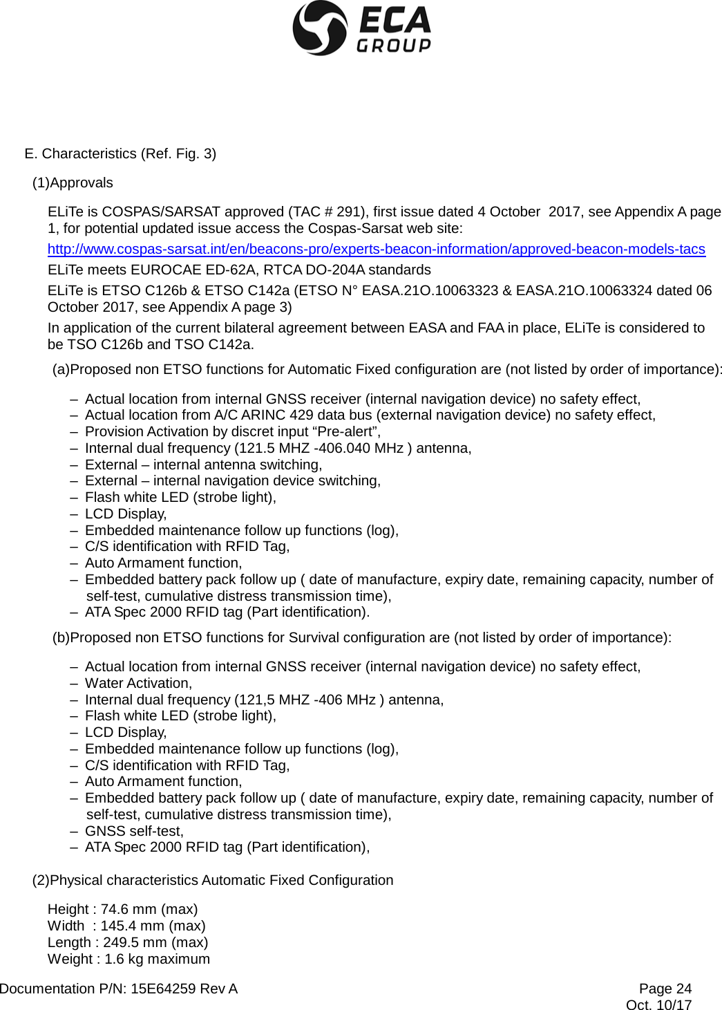
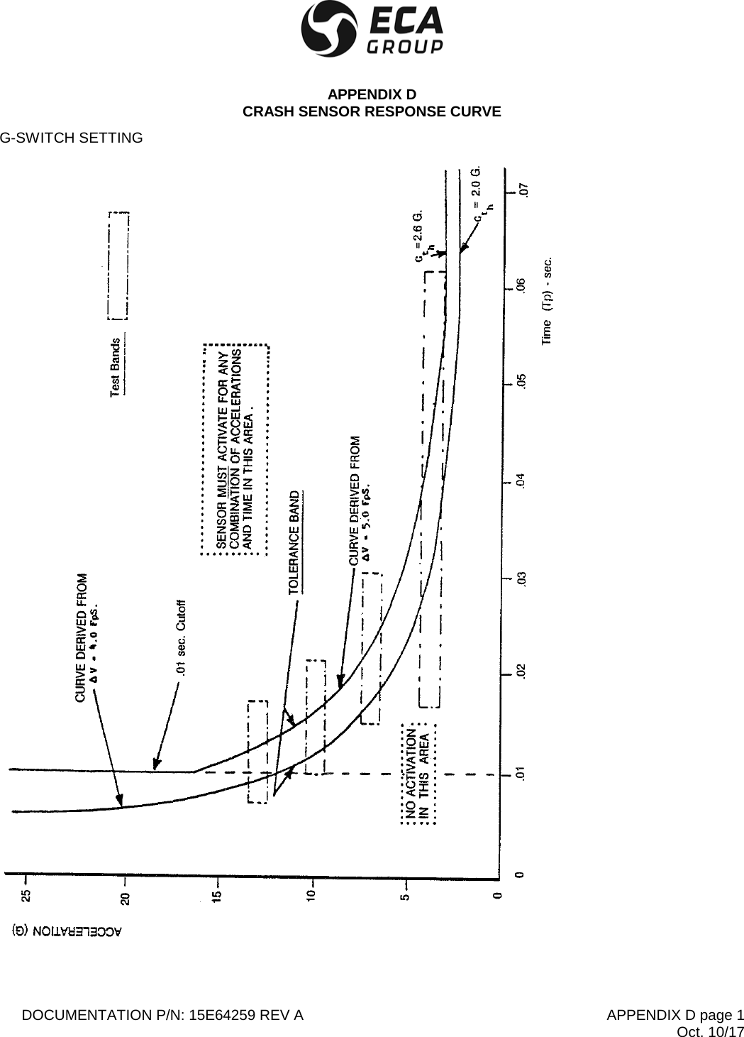
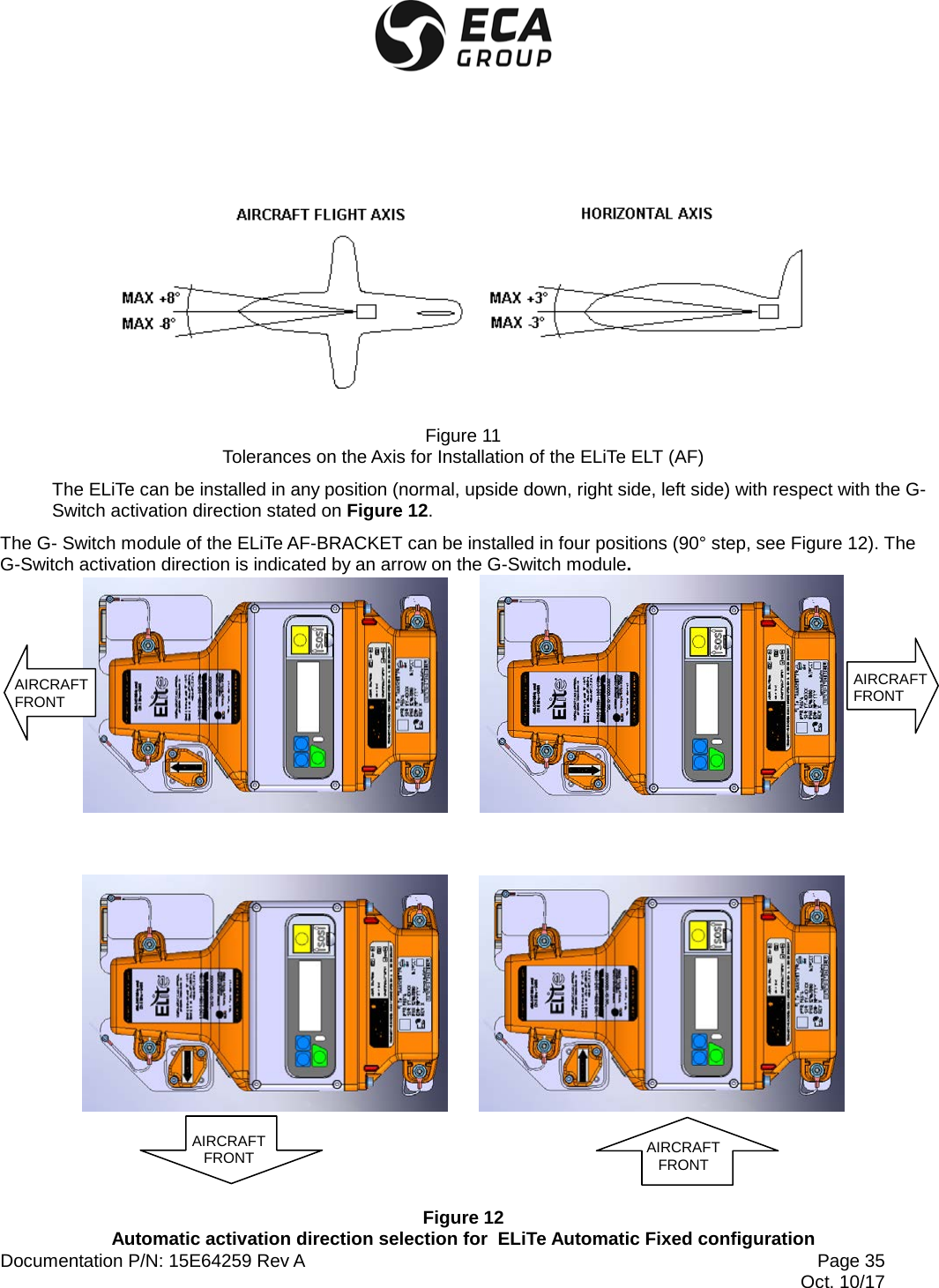
![Documentation P/N: 15E64259 Rev A Page 28 Oct. 10/17 . Aircraft Registration Marking [Tail Number] (up to 7 characters), Example of display on ELiTe TRANSMITTER LCD “AF_SL1_TAILNBR” stands for: Automatic Fixed (AF) using Standard Location Protocol N° 1 [A/C 24 bit Address] for the A/C registration Marking “TAILNBR”. Corresponding Labels present on the relevant ELiTe Coding Tag P/N 12N67890 S/N 17-0075 Definition of the available protocols: . U1, User Protocol, A/C Registration Marking, . U2, User Protocol, ELT serial number, . U3, User Protocol, Operator Designator and ELT serial number, . U4, User Protocol, A/C 24 bit Address, . UL1, User Location Protocol, A/C Registration Marking, . UL2, User Location Protocol, ELT serial number, . UL3, User Location Protocol, Operator Designator and ELT serial number, . UL4, User Location Protocol, A/C 24 bit Address, . SL1, Standard Location Protocol, ELT serial number, . SL2, Standard Location Protocol, Operator Designator and ELT serial number, . SL3, Standard Location Protocol, A/C 24 bit Address, NOTE: For Location Protocols in Automatic Fixed configuration, standard ARINC speed is “High”. If the customer wishes to select ARINC speed “Low”, then the letter “L” is added after the protocol selection giving UL1L, UL2L, UL3L, UL4L, SL1L, SL2L & SL3L. (h)Miscellaneous characteristics in Automatic Fixed configuration – Automatic activation level in accordance with EUROCAE ED-62A / RTCA DO-204A (G-switch module on ELiTe AF-BRACKET, see APPENDIX D activation direction is selectable (4 possible directions 0°, 90°, 180° & 270°, see Figure 12), – Remote control capability: ON/ARMED TEST/RESET ELiTe TRANSMITTER activation indicator. – Provision for future “inflight activation” via an independent discrete input (ground).](https://usermanual.wiki/ELTA/ELITE/User-Guide-4121757-Page-30.png)
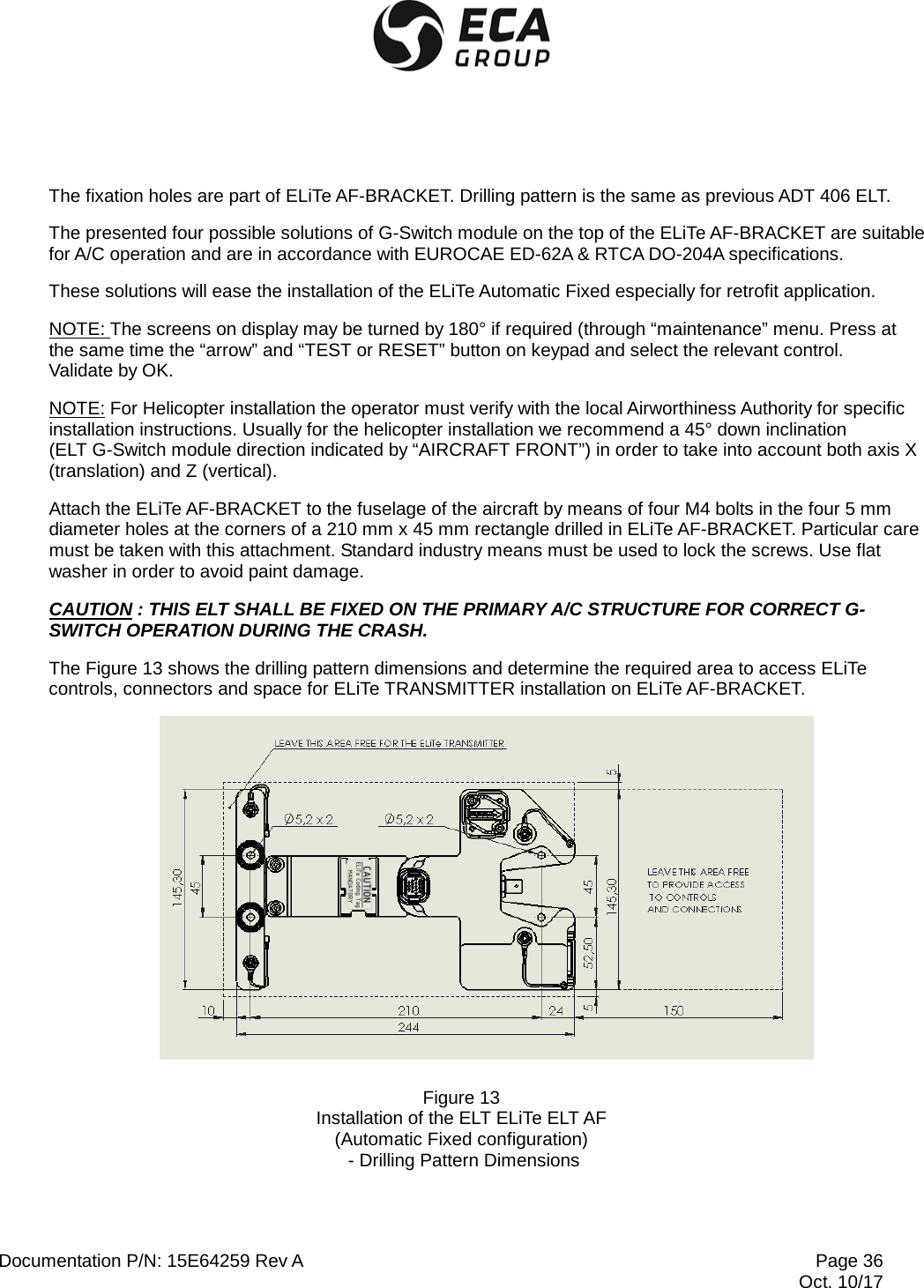
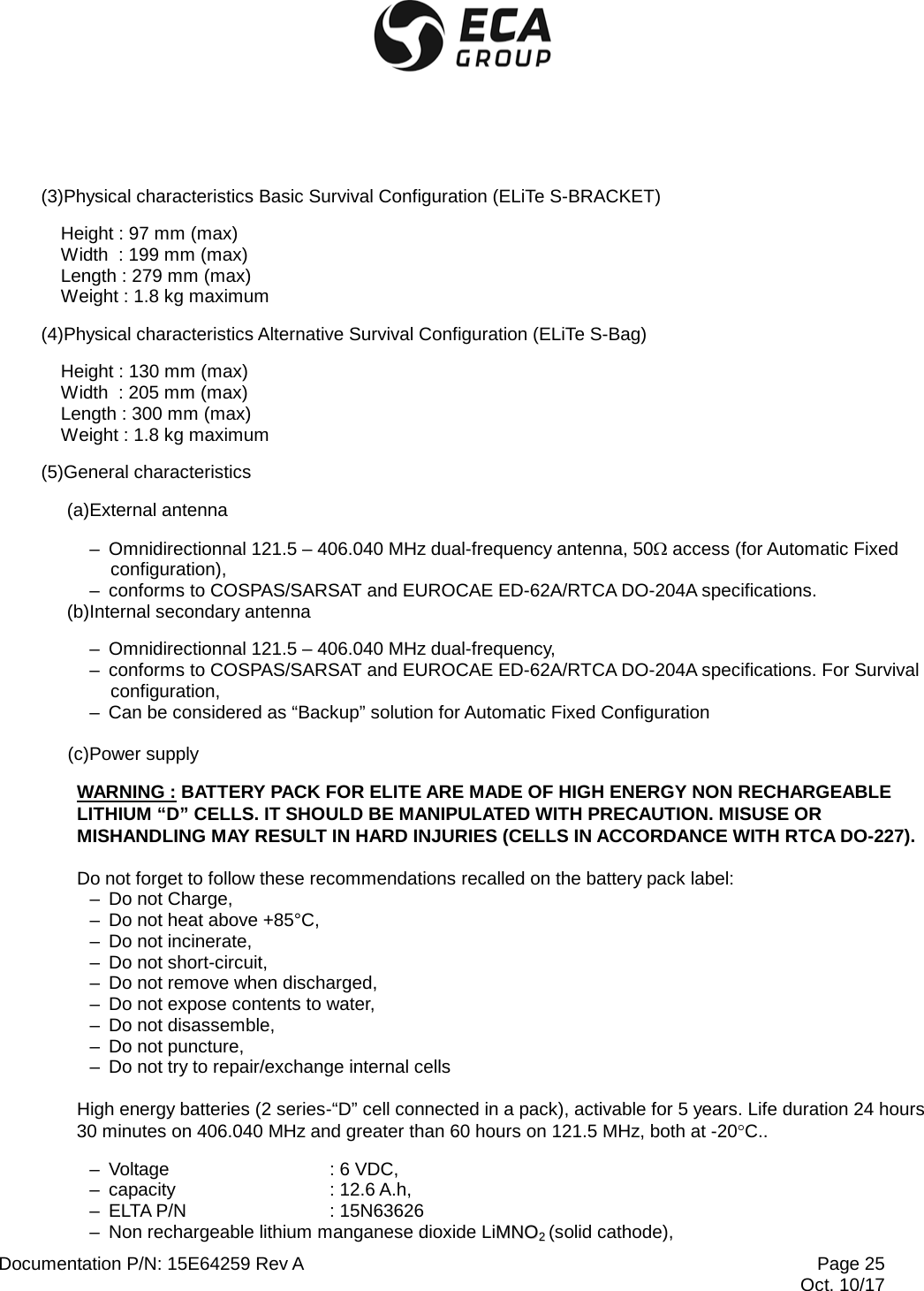
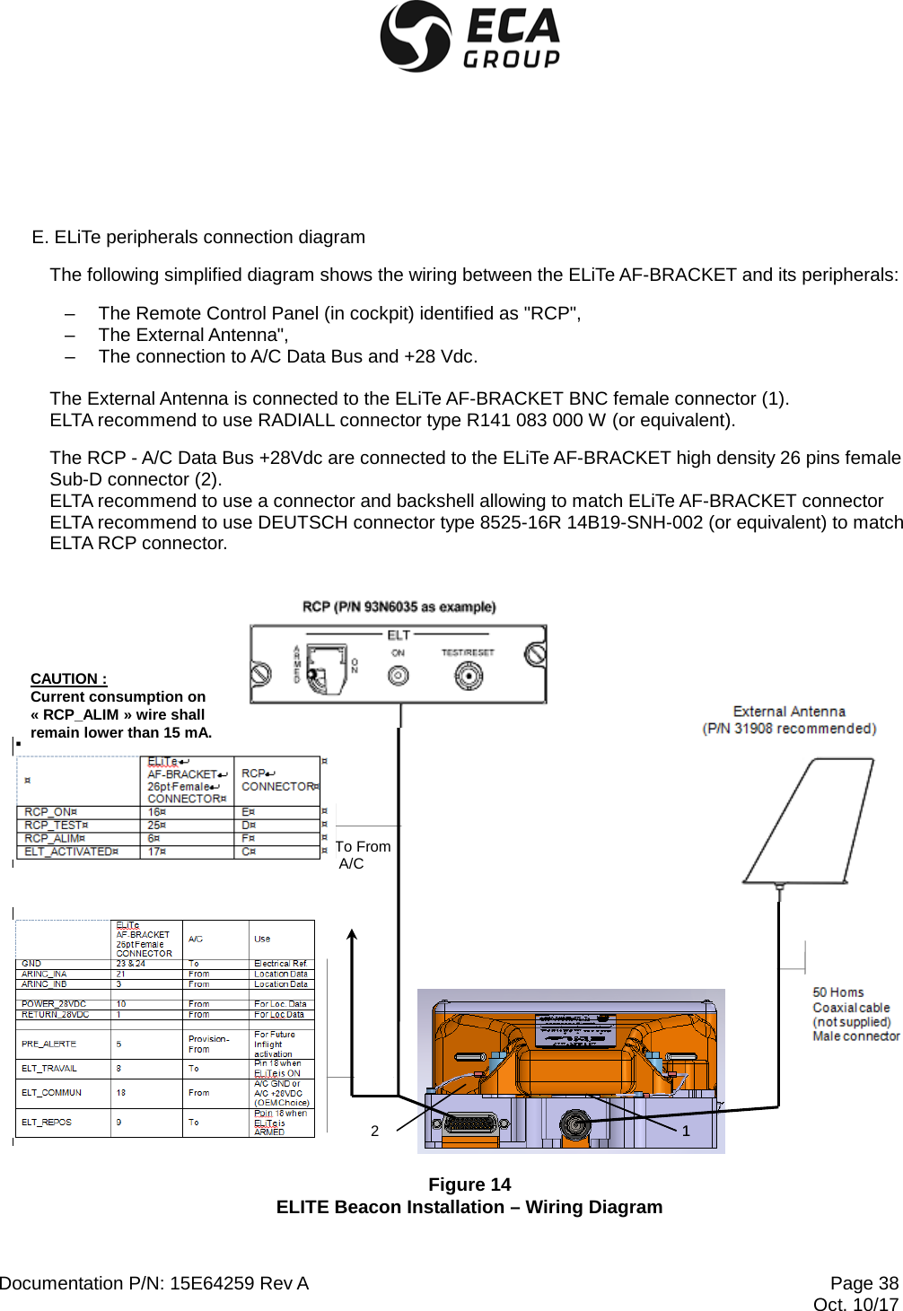
![Documentation P/N: 15E64259 Rev A Page 37 Oct. 10/17 C. External antenna installation ELTA recommend to use P/N 31908 (antenna model 2632-82 manufactured by COBHAM [formerly CHELTON]) for high speed A/C or P/N 28592 (antenna model 1327-82 manufactured by CHELTON) for low speed A/C. Other external antenna may be used but some additional Cospas-Sarsat approval tests shall need to be performed in order to amend the current Type Approval Number (TAC #). Contact ELTA or one of its approved agents to check if the antenna can be used with this ELT model. The external antenna must be installed on the upper part of the fuselage, as far AFT as possible. Particular care must be taken with this attachment. Standard industry means must be used to lock the screws. The contact surface should be reinforced to prevent the antenna from tearing away at high speeds. The cable used shall be of a high quality with very low losses. RG 142 cable type, or equivalent, is recommended. ELTA recommends length lower than 2 meters lowering the risk of rupture in case of crash. Cable RF losses shall remain lower than 1.5 dB. When the coaxial cable is installed and the connectors mated, each end should have some slack in the cable. NOTE: FAA AC 43.13-1b recommends a minimum bend radius of 6 times the outer diameter of coaxial cable. The cable should be secured loosely to aircraft structures for support and protection. Application of fire sleeves meeting the requirements of SAE AS1072 around the coaxial cable is recommended. Coaxial cable connecting the Antenna to the ELT Antenna installation should not cross aircraft production breaks. Connect the connector to the antenna and to the “external antenna. access” on ELiTe AF-BRACKET (BNC connector). D. Remote Control Panel installation The ELiTe Automatic Fixed ELT can be remotely controlled by using a remote control panel installed in the cockpit of the aircraft. We are using “current loop” for the detection of the Remote Control Panel actions (toggle switch and push button), so cable length of this link is not an issue. By experience cable up to 200 meters remains fully operational and do not require grounded cable. This link requires 4 AWG 22 or AWG 24 wires. The only limitation for this application is the DC current drained from the pin 6 (RCP_ALIM) of the ELiTe AF-BRACKET CANON D-SUB 26 pin HD connector that shall remain lower than 15 mA. Refers to Figure 14 for wiring details.](https://usermanual.wiki/ELTA/ELITE/User-Guide-4121757-Page-39.png)
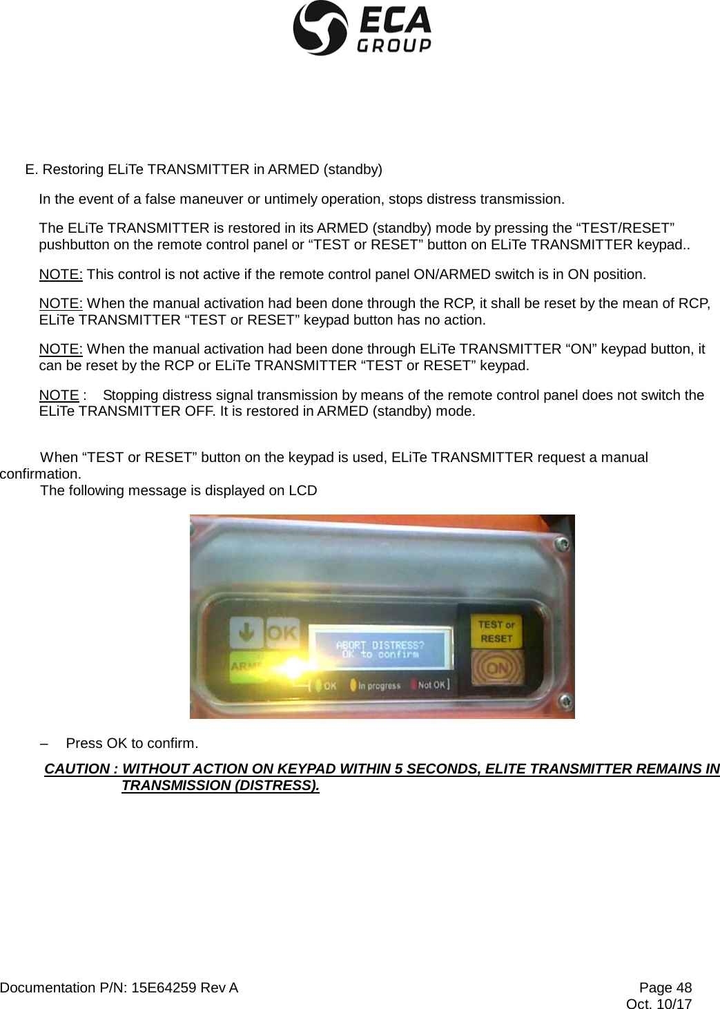
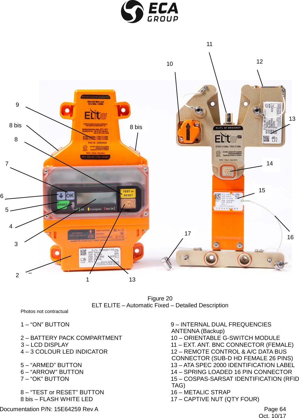
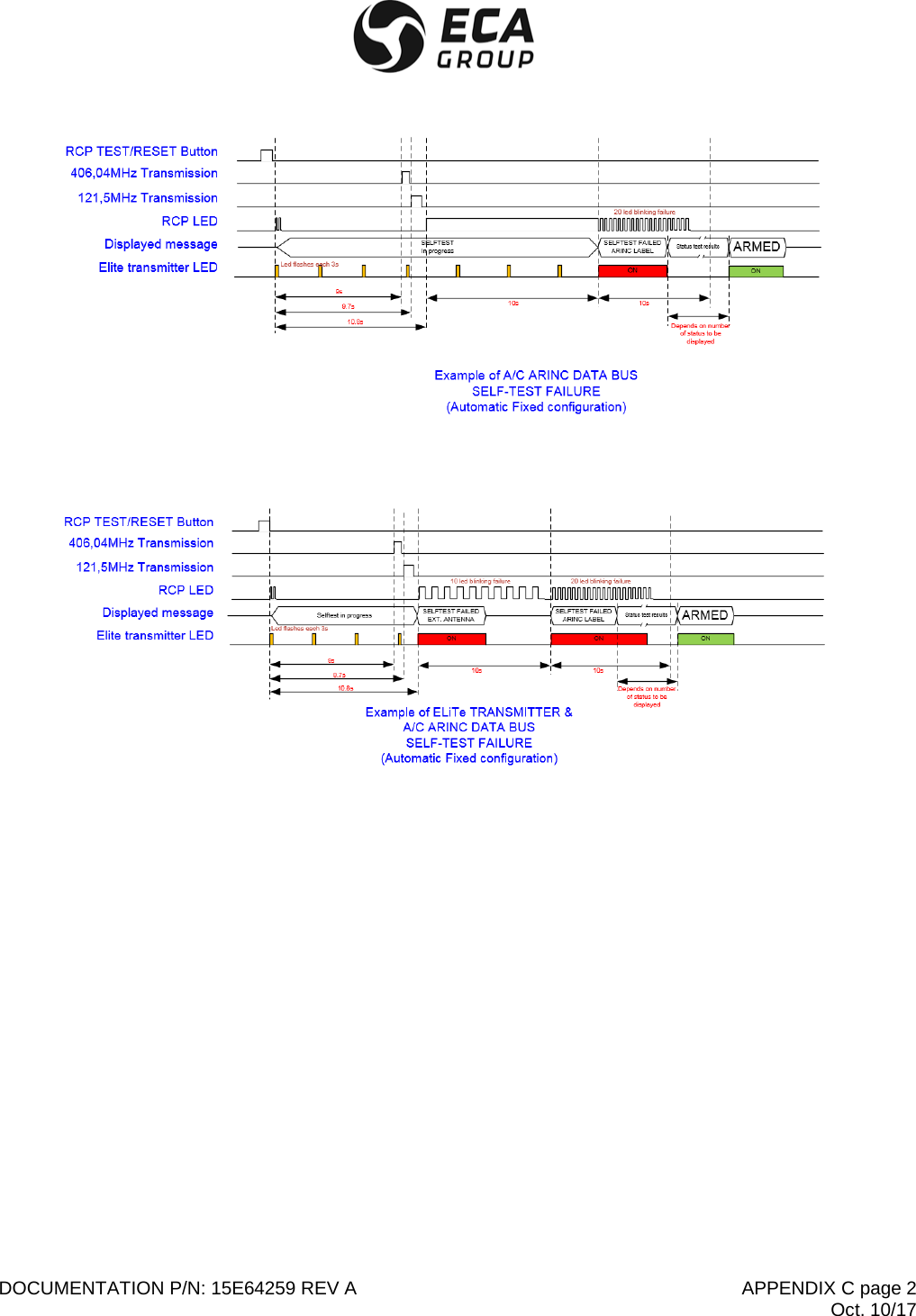
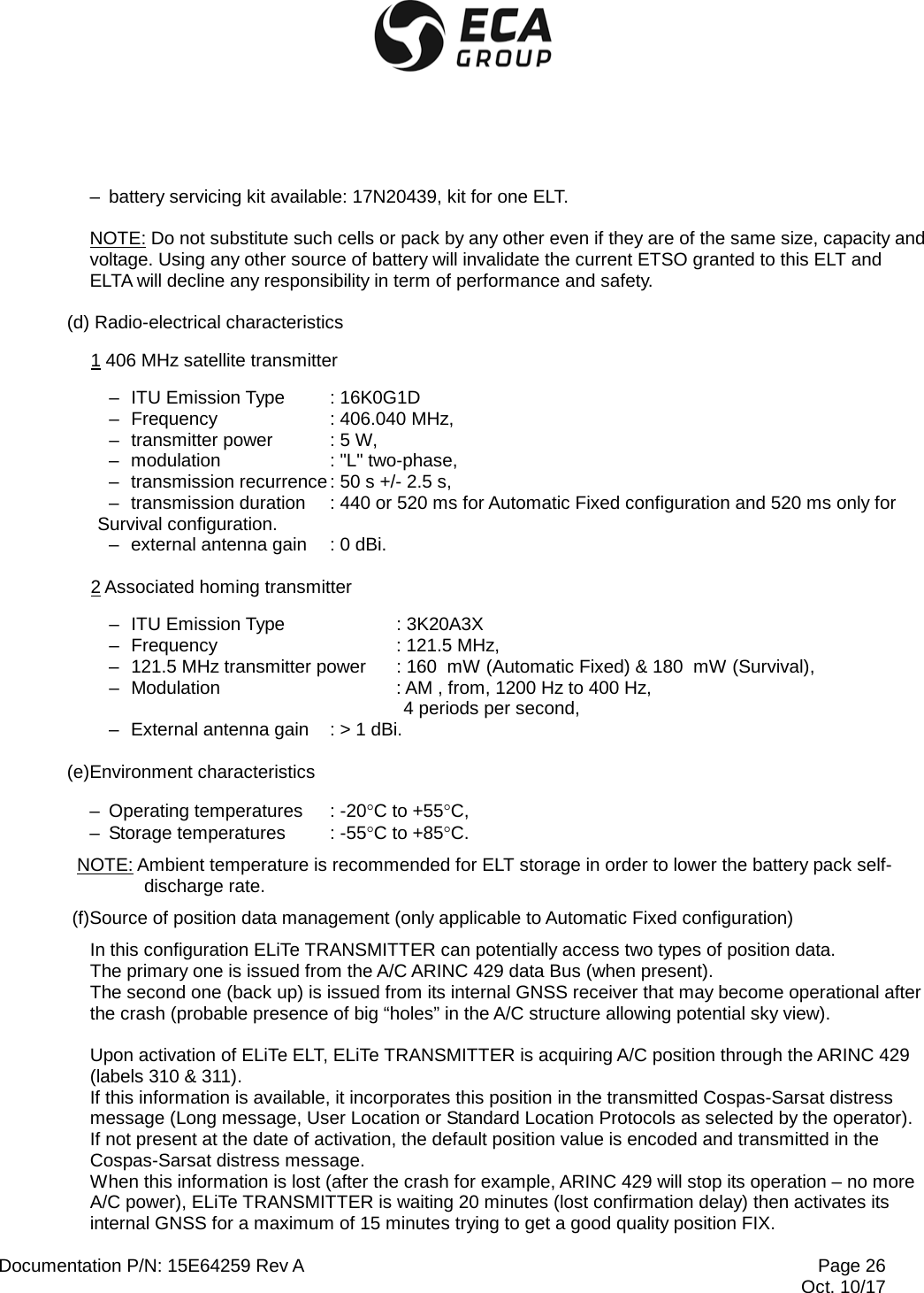
![Documentation P/N: 15E64259 Rev A Page 46 Oct. 10/17 (c) Configuration 8 “Beacon above ground plane” as defined in Cospas-Sarsat C/S T.007 specification, ELiTe ELT is transmitting while kept away from ground (insulated, no need of ground plane). C. Automatic activation CAUTION : IN CASE OF FALSE ACTIVATION OR TEST PURPOSE, THE OPERATOR SHALL STOP THE ELT TRANSMISSION AS DESCRIBED IN § E -RESTORING ELITE TRANSMITTER IN ARMED (STANDBY) WITHIN 50 S. AFTER THIS DELAY THE ELT WILL TRANSMIT ACTUAL DISTRESS SIGNALS ON THE TWO AVAILABLE DISTRESS FREQUENCIES (406.040 & 121.5 MHZ). The acceleration sensor has detected an impact sufficient to trigger it. The LCD display (3) indicates ELiTe TRANSMITTER activation. Upon automatic activation, the ELiTe TRANSMITTER performs one self-test (see §F Beacon self-test 6.F) and displays self-test report on LCD (Figure 20 [3]) In this state, as long as the ELT is in operation, it sends the relevant distress frequencies. D. Manual activations Such manual activation can be achieved either by using ELiTe TRANSMITTER keypad (when accessible) or remote control panel (when available). There are three cases in which a distress signal may be triggered manually:](https://usermanual.wiki/ELTA/ELITE/User-Guide-4121757-Page-48.png)
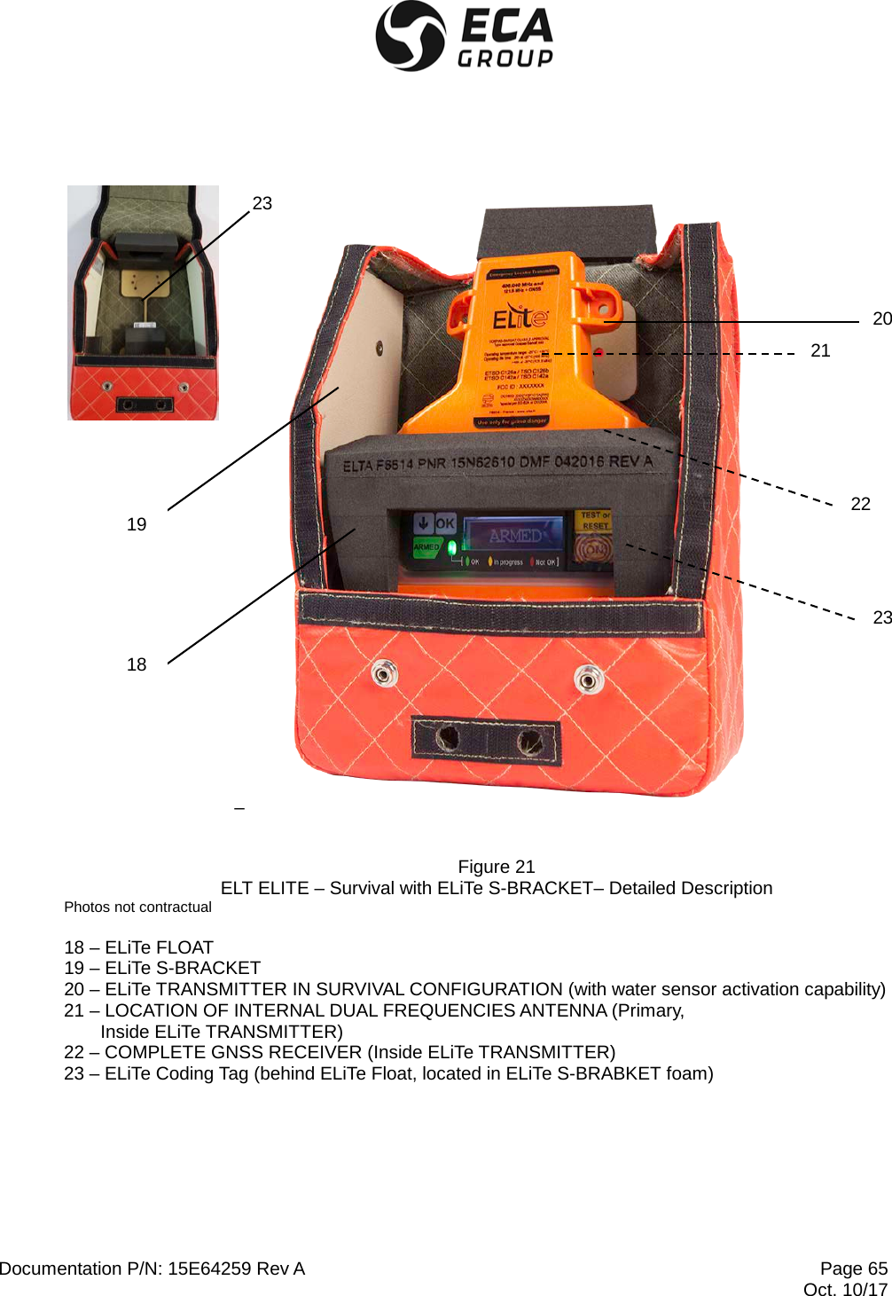
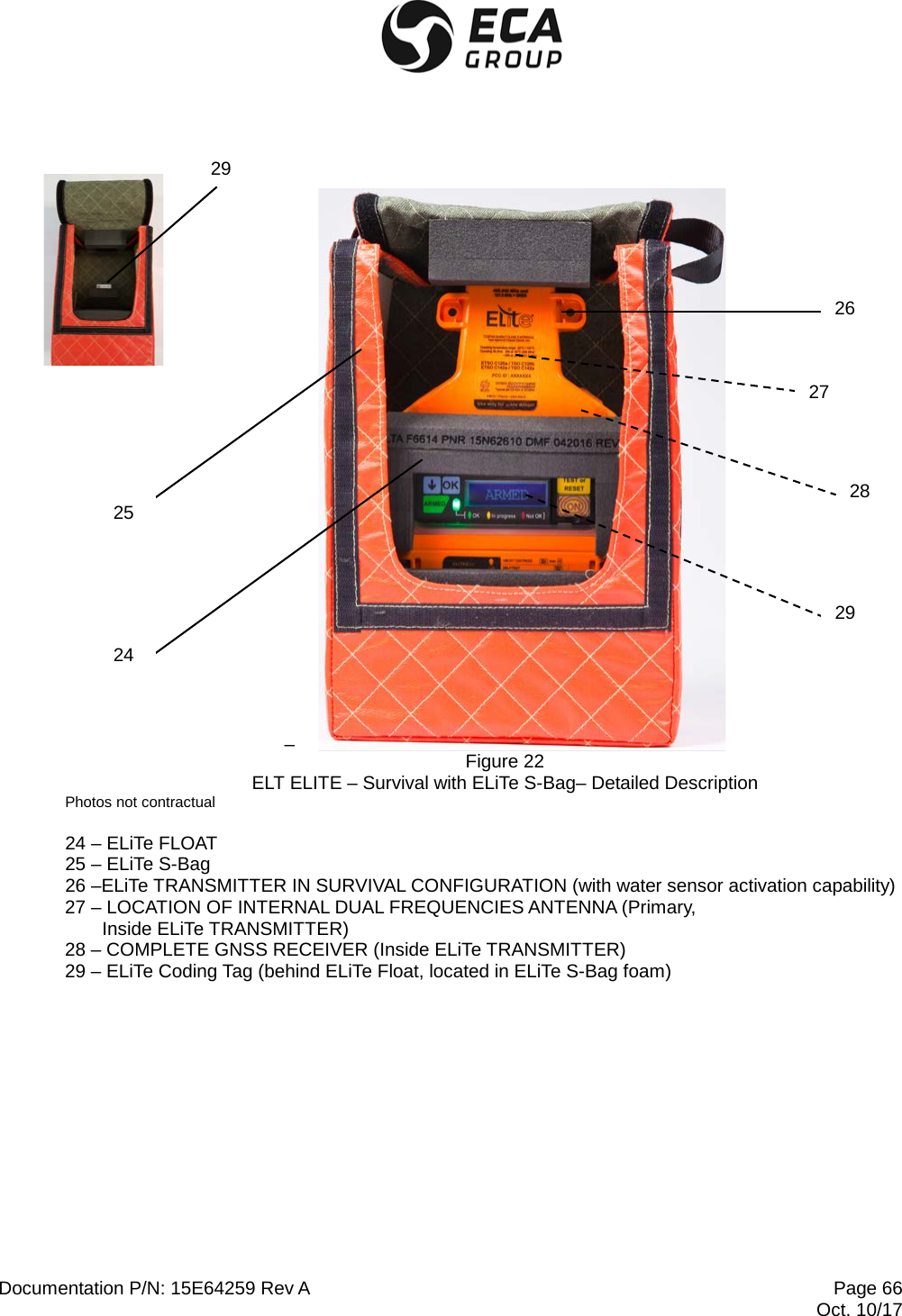
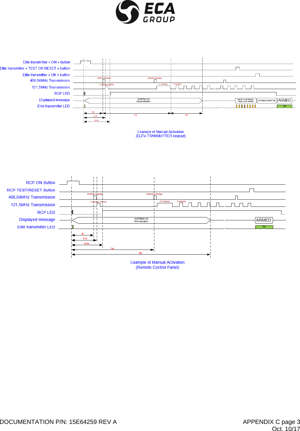
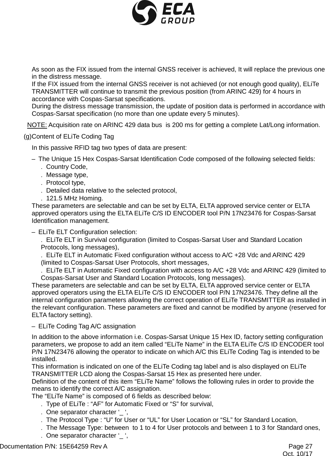
![Documentation P/N: 15E64259 Rev A Page 47 Oct. 10/17 – the acceleration sensor (G-switch) has not been triggered but a distress signal must be sent (injured passengers, aircraft out of operation ...), – the aircraft is on the ground and must be evacuated. – When a crash or ditching condition is imminent. (1) First case: from the Remote Control Panel (Limited to Automatic Fixed configuration) Raise the safety cover (guard) on the remote control panel (RCP) and place the switch in the ON position. After two short blinks on RCP indicator, an automatic self-test sequence is performed (see § F(4) -Self-test by mean of ON on remote control panel (RCP)). CAUTION : IN CASE OF FALSE ACTIVATION THE OPERATOR SHALL STOP THE ELT TRANSMISSION AS DESCRIBED IN § E -RESTORING ELITE TRANSMITTER IN ARMED (STANDBY) WITHIN 50 S. AFTER THIS DELAY THE ELT WILL TRANSMIT ACTUAL DISTRESS SIGNALS ON THE TWO AVAILABLE DISTRESS FREQUENCIES (406.040 & 121.5 MHZ). This transmission state is permanently displayed on the Remote Control Panel indicator. After about 50s delay, the ELiTe TRANSMITTER will transmit the two actual distress frequencies 121.5-406.040 MHz. In this state, as long as the ELT is in operation, it sends the relevant distress frequencies. (2)Second case: from the ELiTe TRANSMITTER front panel (valid for Automatic Fixed & Survival configurations) – Slide the safety transparent cover SOS out of the ON button (1), – Press and release the ON button (Figure 20[1]), An automatic self-test sequence is performed (see § F(3) -Self-test by means of ON button on ELiTe Keypad). CAUTION : IN CASE OF FALSE ACTIVATION THE OPERATOR SHALL STOP THE ELT TRANSMISSION AS DESCRIBED IN § E -RESTORING ELITE TRANSMITTER IN ARMED (STANDBY)-. WITHIN 50 S. AFTER THIS DELAY THE ELT WILL TRANSMIT ACTUAL DISTRESS SIGNALS ON THE TWO AVAILABLE DISTRESS FREQUENCIES (406.040 & 121.5 MHZ). This transmission state is permanently displayed on the Remote Control Panel LED. After about 50s delay, the ELiTe TRANSMITTER will transmit the two actual distress frequencies 121.5-406.040 MHz. In this state, as long as the ELT is in operation, it sends the relevant distress frequencies. NOTE: For Survival configuration, ELiTe TRANSMITTER shall be removed from ELiTe S-BRACKET or ELiTe S-Bag and put in service out of the A/C. It is recommended to attach it to a life raft or survivors in case of ditching.](https://usermanual.wiki/ELTA/ELITE/User-Guide-4121757-Page-49.png)