Users Manual

USER’S HANDBOOK
Documentation P/N: 15E64259 Rev A
Initial issue: Jan. 19/17
Title Page
OCT. 10/17
USER’S HANDBOOK
INCLUDING INSTALLATION GUIDELINES
EMERGENCY LOCATOR TRANSMITTER
MODEL ELiTe:
(IN AUTOMATIC FIXED CONFIGURATION)
(Composed of
One ELiTe TRANSMITTER P/N 12N67880,
One ELiTe AF-BRACKET P/N 12N67900,
One ELiTe Coding Tag P/N 12N67890.)
(IN SURVIVAL CONFIGURATION)
(Composed of
One ELiTe TRANSMITTER P/N 12N67880,
One ELiTe Float P/N 15N62610
One ELiTe S-BRACKET P/N 12N67910,
One ELiTe Coding Tag P/N 12N67890
(Alternative ELiTe S-Bag P/N 12N67920
can replace ELiTe S-BRACKET).)
IN THE COSPAS / SARSAT SYSTEM
Issued by
ELTA F6614
(ECA GROUP)
15 Avenue du Docteur Maurice Grynfogel
31035 TOULOUSE CEDEX 1
France
http://www.elta.fr/index.php/gb/

PAGE INTENTIONALLY LEFT BLANK

Documentation P/N: 15E64259 Rev A Page 1
Oct. 10/17
LIST OF UPDATES
UPDAT
E No. ISSUE INSERTION UPDATE
No. ISSUE INSERTION
DATE BY DATE BY
Preliminary
A –Draft0
A –Draft1
A –Draft2
A - Final
January
19/17
June 22/17
July 12/17
Aug. 08/17
Oct. 10/17
C. CRESP
C. CRESP
C. CRESP
C. CRESP
C. CRESP

Page 2
BLANK
PAGE INTENTIONALLY LEFT BLANK

Documentation P/N: 15E64259 Rev A Page 3
Oct. 10/17
LIST OF EFFECTIVE PAGES
CHAPTER/
SECTION PAGE DATE
CHAPTER/
SECTION PAGE DATE
TITLE PAGE
LISTE OF UPDATES
LIST OF EFFECTIVE PAGE
TABLE OF ILLUSTRATIONS
LEADING PARTICULARS
TABLE OF CONTENTS
INTRODUCTION OF THE C.
GENERAL DETAILS OF
THE ELiTe ELT
DESCRIPTION OF THE
ELiTe ELT AND OF THE AI.
INSTALLATION OF THE
ELiTe AF
1
2
3
4
5
6
7
8
9
10
11
12
13
14
15
16
17
18
19
20
21
22
23
24
25
26
27
28
29
30
31
32
33
34
OCT. 10/17
OCT. 10/17
BLANK
OCT. 10/17
BLANK
OCT. 10/17
BLANK
OCT. 10/17
BLANK
OCT. 10/17
BLANK
OCT. 10/17
OCT. 10/17
OCT. 10/17
OCT. 10/17
OCT. 10/17
OCT. 10/17
OCT. 10/17
OCT. 10/17
OCT. 10/17
OCT. 10/17
OCT. 10/17
OCT. 10/17
OCT. 10/17
OCT. 10/17
OCT. 10/17
OCT. 10/17
OCT. 10/17
OCT. 10/17
OCT. 10/17
OCT. 10/17
OCT. 10/17
OCT. 10/17
OCT. 10/17
OCT. 10/17
INSTALLATION OF THE
ELiTe S
UTILIZATION
MAINTENANCE
GLOSSARY
ELiTe ELT Automatic Fixed
ELiTe ELT Survival S-BRA.
ELiTe ELT Survival S-Bag
APPENDIX A
APPENDIX B
APPENDIX C
APPENDIX D
35
36
37
38
39
40
41
42
43
44
45
46
47
48
49
50
51
52
53
54
55
56
57
58
59
60
61
62
63
64
65
66
1 to 6
1 to 12
1 to 4
1 to 2
OCT. 10/17
OCT. 10/17
OCT. 10/17
OCT. 10/17
OCT. 10/17
OCT. 10/17
OCT. 10/17
OCT. 10/17
OCT. 10/17
OCT. 10/17
OCT. 10/17
OCT. 10/17
OCT. 10/17
OCT. 10/17
OCT. 10/17
OCT. 10/17
OCT. 10/17
OCT. 10/17
OCT. 10/17
OCT. 10/17
OCT. 10/17
OCT. 10/17
OCT. 10/17
OCT. 10/17
OCT. 10/17
OCT. 10/17
OCT. 10/17
OCT. 10/17
OCT. 10/17
OCT. 10/17
OCT. 10/17
OCT. 10/17
OCT. 10/17
OCT. 10/17
OCT. 10/17
OCT. 10/17

Page 4
BLANK
PAGE INTENTIONALLY LEFT BLANK

Page 5
Oct. 10/17
TABLE OF ILLUSTRATIONS
Figure 1 COSPAS/SARSAT – System Principle............................................................................................... 12
Figure 2 ELiTe Automatic Fixed (AF) – Presentation ....................................................................................... 16
Figure 3 ELiTe Automatic Fixed - Sub Components ........................................................................................ 17
Figure 4 Survival – ELiTe S-BRACKET Sub Components ............................................................................... 19
Figure 5 Survival – ELiTe S-Bag Sub Components.......................................................................................... 20
Figure 6 ELiTe Automatic Fixed (AF) Configuration - Overall Dimensions ..................................................... 21
Figure 7 ELiTe Survival Configuration - Overall Dimensions ........................................................................... 22
Figure 8 ELiTe Survival (Bag) – Alternative Solution – Overall Dimensions ..................................................... 23
Figure 9 ELiTe TRANSMITTER - Labels .......................................................................................................... 31
Figure 10 ELiTe AF-BRACKET – Labels .......................................................................................................... 32
Figure 11 Tolerances on the Axis for Installation of the ELiTe ELT (AF) .......................................................... 35
Figure 12 Automatic activation direction selection for ELiTe Automatic Fixed configuration ........................... 35
Figure 13 Installation of the ELT ELiTe ELT AF (Automatic Fixed configuration) - Drilling Pattern Dimensions
.................................................................................................................................................................. 36
Figure 14 ELITE Beacon Installation – Wiring Diagram ................................................................................... 38
Figure 15 ELiTe Float Installation Process ....................................................................................................... 40
Figure 16 ELiTe TRANSMITTER equipped with ELiTe Float ........................................................................... 41
Figure 17 Installation of the ELiTe ELT S (Survival configuration) Drilling Pattern Dimensions ....................... 42
Figure 18 ELiTe Survival - Recommended Configuration ................................................................................ 42
Figure 19 ELiTe Survival - Alternative Configuration ........................................................................................ 43
Figure 20 ELT ELITE – Automatic Fixed – Detailed Description ...................................................................... 64
Figure 21 ELT ELITE – Survival with ELiTe S-BRACKET– Detailed Description ............................................. 65
Figure 22 ELT ELITE – Survival with ELiTe S-Bag– Detailed Description ....................................................... 66

Page 6
BLANK
PAGE INTENTIONALLY LEFT BLANK

Documentation P/N: 15E64259 Rev A Page 7
Oct. 10/17
LEADING PARTICULARS
CAUTION 1 : THIS TRANSMITTER IS AUTHORIZED FOR USE ONLY DURING SITUATIONS OF GRAVE
AND IMMINENT DANGER.
CAUTION 2 : IT IS IMPERATIVE THAT EACH ELT OWNER REGISTERS THEIR ELT (COSPAS-SARSAT
IDENTIFICATION CONTAINED IN ELITE CODING TAG). CONTACT THE LOCAL
AIRWORTHINESS OR ELTA OR APPROVED ELTA AGENT TO OBTAIN THE INFORMATION
RELATIVE TO THIS REGISTRATION AS NECESSARY.
NOTE: Guidelines can be found on the Cospas-Sarsat website (www.cospas-sarssat.org – C/S S.007 Handbook
of regulations on 406 MHz and 121.5 MHz beacons).
CAUTION 3 : THE ELITE CODING TAG MUST IMPERATIVELY BE PROGRAMMED WITH THE RELEVANT
COSPAS-SARSAT IDENTIFICATION AUTHORIZED BY THE LOCAL AIRWORTHINESS.
CAUTION 4 : ONCE THE ELITE CODING TAG HAS BEEN PROGRAMMED, IT IS GENERALY ASSIGNED
TO AN AIRCRAFT (NAME AND IDENTIFICATION). IF THIS ELITE CODING TAG IS
TRANSFERRED TO ON ANOTHER AIRCRAFT OR OPERATOR IT MUST BE
REPROGRAMMED (NEW NAME AND IDENTIFICATION).
CAUTION 5 : BEFORE INSTALLING OR USING THIS ELT, THE VALIDITY OF THE INFORMATION ON
ELITE TRANSMITTER LABELS MUST IMPERATIVELY BE CHECKED (BATTERY EXPIRY,
COSPAS-SARSAT IDENTIFICATION AS A MINIMUM).
CAUTION 6 : ELITE TRANSMITTER WILL GET AUTOMATICALLY ITS COSPAS-SARSAT IDENTIFICATION
FROM ELITE CODING TAG WHEN INSTALLED ON ANY BRACKET OR BAG.
CAUTION 7 : ELITE TRANSMITTER READS ITS COSPAS-SARSAT IDENTIFICATION FROM ELITE
CODING TAG AND STORES IT INTERNALLY NON VOLATILE MEMORY AT EACH SELF-
TEST OR ACTIVATION (MANUAL OR AUTOMATIC) REQUEST.
CAUTION 8 : ELITE TRANSMITTER KEEPS ITS PREVIOUS COSPAS-SARSAT IDENTIFICATION WHEN
REMOVED FROM ANY BRACKET OR BAG.. IT SHALL BE SWITCHED OFF PRIOR ANY
TRANSPORTATION OR MAINTENANCE IN ORDER TO AVOID ANY FALSE ALERT.
CAUTION 9 : IT IS ESSENTIAL TO ENSURE THE ELITE TRANSMITTER IS SUCCESSFULLY CODED ON
INITIAL AND FURTHER INSTALLATIONS INTO THE AIRCRAFT PRIOR TO USE IT IN ORDER
TO AVOID ANY FALSE ALERT BY USING INAPPROPRIATE CODE.
NOTE: Upon removal ELiTe TRANSMITTER keeps its previous C/S coding (see CAUTION 8). Initial (first)
delivery from ELTA is using a generic default code inappropriate for operational use.

Documentation P/N: 15E64259 Rev A Page 8
BLANK
PAGE INTENTIONALLY LEFT BLANK

Documentation P/N: 15E64259 Rev A Page 9
Oct. 10/17
TABLE OF CONTENTS
LIST OF UPDATES 1
LIST OF EFFECTIVE PAGES 3
TABLE OF ILLUSTRATIONS 5
LEADING PARTICULARS 7
TABLE OF CONTENTS 9
1. INTRODUCTION TO THE COSPAS-SARSAT SYSTEM 11
A. The COSPAS-SARSAT* system 11
B. System organization (Ref. Figure 1) 11
C. ELTA and the COSPAS-SARSAT system 13
2. GENERAL DETAILS OF THE ELITE ELT 14
A. Purpose of the ELiTe ELT (Ref. Fig. 2) 14
B. ELiTe ELT principle 14
C. ELiTe ELT Configurations 15
D. ELiTe installed overall dimensions 21
E. Characteristics (Ref. Fig. 3) 24
3. DESCRIPTION OF THE ELITE ELT AND OF THE AIRCRAFT COMPONENTS 30
A. General description 30
B. Detailed description 30
4. INSTALLATION OF THE ELITE AUTOMATIC FIXED CONFIGURATION 34
A. General 34
B. Installation of ELiTe (AF) on the aircraft (Ref. Figure 11) 34
C. External antenna installation 37
D. Remote Control Panel installation 37
E. ELiTe peripherals connection diagram 38
F. Installation and configuration of the ELiTe Automatic Fixed (Ref. Figure 14) 39
5. INSTALLATION OF THE ELITE SURVIVAL CONFIGURATION 39
A. General 39
B. Installation of ELiTe (S) on the aircraft. 40
6. UTILIZATION OF THE ELITE ELT (REF. FIGURE 20) 44
A. General 44
B. Typical Operational scenarios 44
C. Automatic activation 46
D. Manual activations 46
E. Restoring ELiTe TRANSMITTER in ARMED (standby) 48
F. Beacon self-test 49
G. Switching ARMED automatically the ELiTe TRANSMITTER 56
H. Switching ARMED Manually the ELiTe TRANSMITTER 56
I. Switching OFF the ELiTe TRANSMITTER 58
7. MAINTENANCE OF THE ELITE ELT 59
A. Beacon self-test 59
B. Maintenance periodicity table 62
C. Batteries replacement (ELiTe TRANSMITTER only) 62
D. Batteries discarding 62
E. Test to do at the time of a beacon return in workshop 63
F. ELiTe Coding Tag access for ELiTe Cospas-Sarsat Identification update. 63
8. GLOSSARY 63

Page 10
BLANK
PAGE INTENTIONALLY LEFT BLANK

Documentation P/N: 15E64259 Rev A Page 11
Oct. 10/17
1. INTRODUCTION TO THE COSPAS-SARSAT SYSTEM
A. The COSPAS-SARSAT* system
The purpose of the COSPAS-SARSAT satellite system is to detect and locate all distress signals transmitted
by aeronautical, maritime or land-based beacons, for the search and rescue organizations.
This program is the result of an international collaboration between the United States, Canada and France
on the one hand (SARSAT project), and Russia on the other hand (COSPAS project). These two projects
are fully compatible.
Since the first results were obtained several countries have joined the program. Other countries continue to
join the COSPAS-SARSAT system partners.
ELTA in relation with CNES (French National Space Agency) has developed the complete range of products
required for COSPAS-SARSAT system operation. Now ELTA is focusing in the design and production of
ELT’.
Following an in-depth study phase, ELTA has arrived at highly conclusive technical results. Experimental and
operational use of the "ground" equipment have proven this equipment's reliability and ease-of-use.
At the end of 2015 the total estimated Cospas-Sarsat beacon is about 2,000,000.
From 1982 (date of the official Cospas-Sarsat system entry to service) to end of 2015, at least 41,750
persons have been saved thanks to Cospas-Sarsat use.
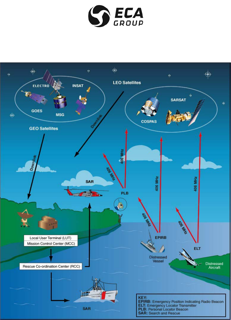
B. System organization (Ref. Figure 1)
In the COSPAS-SARSAT system, space equipment is placed on board several satellites in low near-polar
orbit to capture transmissions from emergency transmitters and to retransmit these signals to specialized
ground stations called Local User Terminals (LUT). These ground stations determine the position of the
emergency transmitters and then retransmit the position data to the designated Mission Control Centers
(MCC). The MCCs in turn retransmit these data to the appropriate Rescue Coordination Centers (RCC) so
that they can start the search and rescue operations.
Documentation P/N: 15E64259 Rev A Page 12
Oct. 10/17
Figure 1
COSPAS/SARSAT – System Principle
(courtesy of Cospas-Sarsat)
COSPAS-SARSAT means:
COSPAS = Kosmicheskaya Sistyema Poiska Avariynych Sudov
SARSAT = Search and Rescue Satellite-Aided Tracking

Documentation P/N: 15E64259 Rev A Page 13
Oct. 10/17
There are several advantages to using the 406 MHz frequency:
– Worldwide coverage: locating is not only possible in real-time within a radius of 2,500 km around the
station, but also in global mode outside this zone since the satellites memorize the messages on the
406 MHz frequency. Location process uses Doppler effect.
– Locating accuracy: 2 km as opposed to 10 to 15 km in the 121.5 MHz frequency. It should be noted
however that the 406 MHz beacons also transmit 121.5 MHz signal which enable the final approach of
the rescue teams in homing mode.
– Information reliability: the structure of the digital signal transmitted by these beacons makes it possible
to be sure that there is actually a distress situation, as well as to identify automatically the mobile in
distress which is vital for rescue operations.
– Unique identification: each beacon has it’s own identification information.
– Possibility to incorporate local Position data (GNSS) in the 406 MHz transmitted message
C. ELTA and the COSPAS-SARSAT system
(1) 406 MHz distress beacons:
These beacons transmit to the satellites a digital message which identifies them and gives their position,
as well as a signal that facilitates the final approach of the rescue teams.
They are suitable for all types of use (maritime, aeronautical and land) and can, depending on the model,
be activated manually or automatically. They are designed to function in the most extreme conditions with
a high degree of reliability.
(2) Low earth orbiting satellites:
At least four satellites are permanently operational. Since their orbit is near-polar, in the worst case every
point on Earth is overflown every two hours.
In a ground station's visibility zone, the satellites directly transmit the messages captured in that zone,
and also any messages from the zones not covered that they have stored in memory.
(3) Geo-stationary satellites are now available in the system and offer faster detection capability (close to 5
minutes) but require a GPS receiver to supply location that is sent via C/S message.
(4) Medium earth orbiting satellites:
In a very near future, such satellites will be added to Cospas-Sarsat System. They will improve the
Cospas-Sarsat performances and will allow the introduction of second generation ELT. They are not yet
operational.
(5)Ground reception stations:
The zone effectively covered (or visibility zone) is a circle with a radius of 2,500 km around the station.
These stations receive (via the satellites) and process:
• in real time, the messages from the beacons activated in their visibility zone and,
• in batch mode, the messages from the 406 MHz beacons activated outside that visibility zone and
memorized by the satellites.
Automatic processing of the 406 MHz digital messages allows the beacons to be located and the mobile
carrier to be identified.

Documentation P/N: 15E64259 Rev A Page 14
Oct. 10/17
2. GENERAL DETAILS OF THE ELiTe ELT
A. Purpose of the ELiTe ELT (Ref. Fig. 2)
With ELiTe ELT, ELTA proposes a new patented concept based on the supply of one unique Cospas-Sarsat
distress transmitter available for both Automatic Fixed and Survival ELT applications.
The ELiTe ELT is designed to transmit a digital distress signal to satellites that are part of the
COSPAS/SARSAT SYSTEM.
These satellites transmits the captured signal to the reception stations on the ground (LUT).
This signal is transmitted on the 406.040 MHz frequency and is used to precisely locate and identify the
ELiTe ELT.
It also transmits a 121.5 MHz signal to facilitate the final approach of the distress scene (final homing).
This ELT meets the latest ICAO and EOPS recommendations. It is ETSO C126b, ETSO C142a approuved.
Through the current EASA/FAA bilateral agreement it is automatically recognized as TSO C126b and TSO
C42a.
B. ELiTe ELT principle
ELiTe ELT principle is based on the association of the unique transmitter (ELiTe TRANSMITTER) and
dedicated mounting brackets (ELiTe AF-BRACKET or ELiTe S-BRACKET, or alternative storage and
transportation bag ELiTe S-Bag). It is this association that offers the final ELT type i.e. Automatic Fixed (AF)
or Survival (S).
The purpose of the ELiTe Coding Tag is to store on board the A/C the Cospas-Sarsat identification.
The Cospas-Sarsat Identification is memorized in an independent non-volatile memory located in this
dedicated passive wireless radio frequency device (very short range RFID technology).
This part is located on the ELiTe AF-BRACKET, or in ELiTe S-BRACKET or in ELiTe S-Bag, the alternative
storage and transportation bag of ELiTe S-BRACKET.
This part can be attached to the A/C structure by the mean of a metallic strap, when required.
It will keep, on board the A/C, the Cospas-Sarsat Identification code.
Upon any type of activation (automatic of manual) or after each self-test, ELiTe TRANSMITTER is acquiring
this relevant Cospas-Sarsat Identification Code and will use it to transmit the correct distress signal on
406.040 MHz.
The operator is then sure that any new ELiTe TRANSMITTER installed on/in its relevant bracket will transmit
the correct Cospas-Sarsat message upon it’s activation.
NOTE: Such wireless communication between ELiTe TRANSMITTER and ELiTe Coding Tag is a very short
range one, only few mm avoiding any risk of duplication/error.
NOTE: A copy of this Cospas-Sarsat ID code is made internally by ELiTe TRANSMITTER in non volatile
memory at each self-test or activation request allowing correct transmission even when the transmitter is
removed from its bracket (case of the Survival configuration) or in case of ELiTe Coding Tag access failure
(any type of ELiTe configuration).
During self-test process, the transmitter indicates the presence or absence of a valid ELiTe Coding Tag
content. Any change i.e. new ELiTe Coding Tag, (so new Cospas-Sarsat ID code) is detected.
If the ELiTe Coding Tag is absent or damaged (after the first installation correct reading), the transmitter will
use its internal copy for Cospas-Sarsat identification for the distress transmission (backup mode).

Documentation P/N: 15E64259 Rev A Page 15
Oct. 10/17
As a consequence when the transmitter is removed from its bracket it can transmit the relevant C/S ID (from
its internal backup memory).
Transmission will be made with the “last acquired” ELiTe Coding Tag content.
NOTE: When ELiTe TRANSMITTER is removed for maintenance or transportation it is important to put it in
the “OFF” mode avoiding any transmission (false alert possibility).
Valid Cospas-Sarsat Identification is indicated on the ELiTe Coding Tag label and is also displayed on the
ELiTe TRANSMITTER LCD display at each self-test or activation.
If the ELT ownership change, the ELiTe Coding Tag shall be re-coded in order to get a new unique 15 digit
Hex Code, with the appropriate new country code and new coding protocol as selected or required by the
country of the new final operator. Contact ELTA for additional details (www.elta.fr ) as necessary.
Coding of the ELiTe Coding Tag is realized using the dedicated ELiTe C/S ID ENCODER TOOL
P/N 17N23476 (see CMM 25-60-17 for detail) constituted of a PC software and RFID tag reader/writer USB
interface.
NOTE: In addition to the Cospas-Sarsat identification data, additional “configuration data” are stored inside
the nonvolatile memory of the ELiTe Coding Tag. As a consequence an ELiTe Coding Tag encoded for and
Automatic Fixed configuration shall not be used for Survival configuration and vice versa.
These “configuration data” are factory set at ELTA and cannot be modified by the dedicated
ELiTe C/S ID ENCODER TOOL P/N 17N23476 avoiding any wrong use of the intended ELiTe ELT
(Automatic Fixed or Survival).
C. ELiTe ELT Configurations
(1) ELiTe ELT in the AUTOMATIC FIXED CONFIGURATION
In this configuration, ELiTe is an Automatic Fixed Emergency Locator Transmitter (ELT) distress beacon.
ELiTe TRANSMITTER can be removed (example for maintenance) and ELiTe AF-BRACKET remains
installed and connected onboard the A/C (reliability improvement).
ELiTe TRANSMITTER gets the relevant COSPAS-SARSAT Identification from ELiTe Coding Tag located on
ELiTe AF-BRACKET.
In this Automatic Fixed (AF) configuration, It can be triggered manually (either from remote control panel
located in the cockpit or from ELiTe TRANSMITTER keypad) or automatically by means of an acceleration
sensor (G-switch, located on ELiTe AF-BRACKET) in accordance to EUROCAE ED-62A / RTCA DO-204A
standards.
Any encoding User, User Location and Standard Location protocols defined by Cospas/Sarsat can be used
in this configuration including country code assignation.
When ELiTe AF-BRACKET is connected to A/C +28 Vdc and A/C ARINC 429 Data Bus, it can receive the
A/C location (Latitude & Longitude). This information is then incorporated in the Cospas-Sarsat Identification
encoded as “Long”. Message location accuracy transmitted is truncated to 4’ of angle (about 5 Km) for User
Location protocol or 4” of angle (about 500 m) for Standard Location protocol as specified by Cospas-
Sarsat).
Basic User Protocols can be use with the Automatic Fixed configuration when there is no possibility to get
access to location data from the A/C.
Documentation P/N: 15E64259 Rev A Page 16
Oct. 10/17
Figure 2
ELiTe Automatic Fixed (AF) – Presentation
Photo Not Contractual
ELiTe TRANSMITTER
P/N 12N67880
ELiTe AF BRACKET
P/N 12N67900
ELiTe Coding Tag
P/N 12N67890, is
located on
ELiTe AF BRACKET
under
ELiTe TRANSMITTER
Battery Pack
compartment

Documentation P/N: 15E64259 Rev A Page 17
Oct. 10/17
Figure 3
ELiTe Automatic Fixed - Sub Components
Photo Not Contractual
Access to
Remote Control Panel (RCP),
A/C ARINC 429 Bus,
A/C +28 Vdc
ELiTe Coding Tag
(Content C/S ID)
CAUTION :
THIS PART IS
MANDATORY
FOR CORRECT
AUTOMATIC FIXED
OPERATIONS.
Metallic
Strap
Access to
External Antenna (BNC)
ELiTe AF-BRACKET
ELiTe TRANSMITTER
Connector
Internal 406 & 121.5 MHz
antenna
Internal GNSS
device
(receiver &
antenna)
Display and
keyboard controls
Battery Pack
Automatic Activation module (G-Switch)
CAUTION : THIS MODULE IS MANDATORY FOR
CORRECT AUTOMATIC FIXED OPERATIONS.
White Flash
LED (qty 2)
Three
colored
LED

Documentation P/N: 15E64259 Rev A Page 18
Oct. 10/17
(2) ELiTe ELT in the SURVIVAL CONFIGURATION
In Survival (S) configuration it can be triggered manually from ELiTe TRANSMITTER keypad in accordance
with EUROCAE ED-62A / RTCA DO-204A standards.
In addition ELiTe ELT proposes another mean of activation using a water sensor located on ELiTe
TRANSMITTER.
NOTE: It is not considered as “Automatic activation” per ICAO standard.
NOTE: This water sensor is inoperative in automatic fixed configurations.
Any encoding User Location or Standard Location protocols defined by COSPAS/SARSAT (C/S) can be
used in this configuration including country code assignation.
NOTE: Basic User protocols cannot be used with the Survival configuration as it not type approved by
Cospas-Sarsat.
Documentation P/N: 15E64259 Rev A Page 19
Oct. 10/17
(a) Standard solution using ELiTe S-BRACKET
In this configuration ELiTe is a Survival Emergency Locator Transmitter (ELT) distress beacon.
ELiTe TRANSMITTER can be removed (example for maintenance) and ELiTe S-BRACKET remains
installed onboard the A/C. There is no connection/wiring with the A/C in this configuration.
ELiTe TRANSMITTER gets the relevant COSPAS-SARSAT Identification from ELiTe Coding Tag stored and
located in an internal foam of ELiTe S-BRACKET.
ELiTe TRANSMITTER equipped with ELiTe Float shall be removed from ELiTe S-BRACKET for correct
distress signal transmission to Cospas-Sarsat satellite (not intended to remain in the bracket while activated)
Figure 4
Survival – ELiTe S-BRACKET Sub Components
Photo Not Contractual
ELiTe TRANSMITTER
P/N 12N67880)
(includes Water Sensor
for additional
Activation)
ELiTe Float
P/N 15N62610
ELiTe S-BRACKET
P/N 12N67910
ELiTe Coding Tag
P/N 12N67890
(contains C/S ID)Is
located inside
ELiTe SBRACKET
under
ELiTe TRANSMITTER
ELiTe S-BRACKET Closed
as installed onboard A/C.
NOTE: It is made of textile,
so it is easy to verify if
ELiTe TRANSMITTER is
present or not inside (touch
& visual inspection)
Documentation P/N: 15E64259 Rev A Page 20
Oct. 10/17
(b) Alternative solution using ELiTe S-Bag
ELTA can propose an alternative Survival solution replacing the ELiTe S-BRACKET by ELiTe S-Bag.
Concept is similar (same materials), but there is no mean for A/C fixation and ELiTe S-Bag is equipped with
a Velcro strap allowing an easier transportation.
In this configuration ELiTe is a Survival Emergency Locator Transmitter (ELT) distress beacon.
ELiTe TRANSMITTER can be removed (example for maintenance) and ELiTe S-Bag may or may not remain
installed onboard the A/C. There is no connection/wiring with the A/C in this configuration.
ELiTe TRANSMITTER gets the relevant COSPAS-SARSAT Identification from ELiTe Coding Tag stored and
located in an internal foam of ELiTe S-Bag.
ELiTe TRANSMITTER equipped with ELiTe Float shall be removed from ELiTe S-Bag for correct distress
signal transmission to Cospas-Sarsat satellite (not intended to remain in the bag while activated).
Figure 5
Survival – ELiTe S-Bag Sub ComponentsPhoto Not Contractual
ELiTe TRANSMITTER
P/N 12N67880)
(includes Water Sensor
for additional
Activation)
ELiTe Float
P/N 15N62610
ELiTe Coding Tag
P/N 12N67890
(contains C/S ID)Is
located inside
ELiTe SBRACKET
behind
ELiTe TRANSMITTER
ELiTe S-Bag Closed as
installed onboard A/C.
NOTE: It is made of textile,
so it is easy to verify if
ELiTe TRANSMITTER is
present or not inside (touch
& visual inspection)
ELiTe S-Bag
P/N 12N67910

Documentation P/N: 15E64259 Rev A Page 21
Oct. 10/17
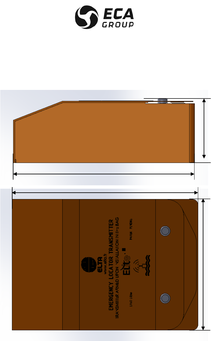
D. ELiTe installed overall dimensions
(1) ELiTe in automatic fixed configuration
Figure 6
ELiTe Automatic Fixed (AF) Configuration - Overall Dimensions
Mandatory required for correct Automatic Fixed operation:
• One ELiTe TRANSMITTER,
• One ELiTe AF-BRACKET
• One ELiTe Coding Tag
74.6 mm
(max)
249.5 mm (max)
249.5 mm (max)
145.4 mm
(max)
145.4 mm
(max)
Documentation P/N: 15E64259 Rev A Page 22
Oct. 10/17
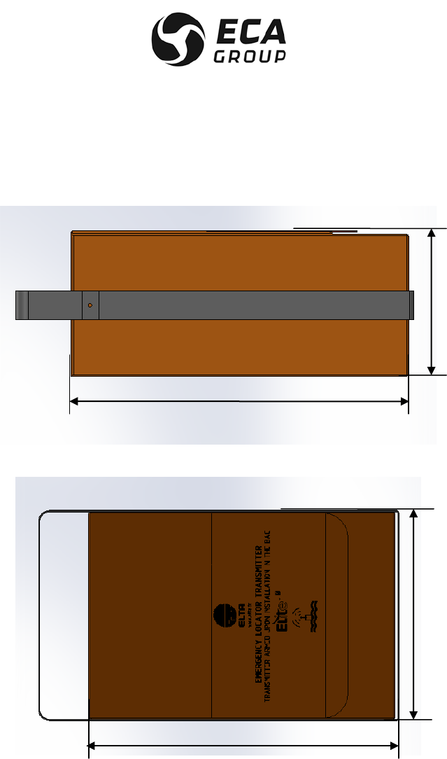
(2) ELiTe in Survival configuration (standard)
Figure 7
ELiTe Survival Configuration - Overall Dimensions
Mandatory required for correct Survival operation:
• One ELiTe TRANSMITTER,
• One ELiTe Float
• One ELiTe S-BRACKET
• One ELiTe Coding Tag
97 mm
(max)
279 mm (max)
249.5 mm (max)
199 mm
(max)
Documentation P/N: 15E64259 Rev A Page 23
Oct. 10/17
(3) ELiTe in Survival configuration (alternative)
Figure 8
ELiTe Survival (Bag) – Alternative Solution – Overall Dimensions
Mandatory required for correct Survival operation:
• One ELiTe TRANSMITTER,
• One ELiTe Float
• One ELiTe S-Bag
• One ELiTe Coding Tag
205 mm
(max)
300 mm (max)
130 mm
(max)
300 mm (max)

Documentation P/N: 15E64259 Rev A Page 24
Oct. 10/17
E. Characteristics (Ref. Fig. 3)
(1)Approvals
ELiTe is COSPAS/SARSAT approved (TAC # 291), first issue dated 4 October 2017, see Appendix A page
1, for potential updated issue access the Cospas-Sarsat web site:
http://www.cospas-sarsat.int/en/beacons-pro/experts-beacon-information/approved-beacon-models-tacs
ELiTe meets EUROCAE ED-62A, RTCA DO-204A standards
ELiTe is ETSO C126b & ETSO C142a (ETSO N° EASA.21O.10063323 & EASA.21O.10063324 dated 06
October 2017, see Appendix A page 3)
In application of the current bilateral agreement between EASA and FAA in place, ELiTe is considered to
be TSO C126b and TSO C142a.
(a)Proposed non ETSO functions for Automatic Fixed configuration are (not listed by order of importance):
– Actual location from internal GNSS receiver (internal navigation device) no safety effect,
– Actual location from A/C ARINC 429 data bus (external navigation device) no safety effect,
– Provision Activation by discret input “Pre-alert”,
– Internal dual frequency (121.5 MHZ -406.040 MHz ) antenna,
– External – internal antenna switching,
– External – internal navigation device switching,
– Flash white LED (strobe light),
– LCD Display,
– Embedded maintenance follow up functions (log),
– C/S identification with RFID Tag,
– Auto Armament function,
– Embedded battery pack follow up ( date of manufacture, expiry date, remaining capacity, number of
self-test, cumulative distress transmission time),
– ATA Spec 2000 RFID tag (Part identification).
(b)Proposed non ETSO functions for Survival configuration are (not listed by order of importance):
– Actual location from internal GNSS receiver (internal navigation device) no safety effect,
– Water Activation,
– Internal dual frequency (121,5 MHZ -406 MHz ) antenna,
– Flash white LED (strobe light),
– LCD Display,
– Embedded maintenance follow up functions (log),
– C/S identification with RFID Tag,
– Auto Armament function,
– Embedded battery pack follow up ( date of manufacture, expiry date, remaining capacity, number of
self-test, cumulative distress transmission time),
– GNSS self-test,
– ATA Spec 2000 RFID tag (Part identification),
(2)Physical characteristics Automatic Fixed Configuration
Height : 74.6 mm (max)
Width : 145.4 mm (max)
Length : 249.5 mm (max)
Weight : 1.6 kg maximum

Documentation P/N: 15E64259 Rev A Page 25
Oct. 10/17
(3)Physical characteristics Basic Survival Configuration (ELiTe S-BRACKET)
Height : 97 mm (max)
Width : 199 mm (max)
Length : 279 mm (max)
Weight : 1.8 kg maximum
(4)Physical characteristics Alternative Survival Configuration (ELiTe S-Bag)
Height : 130 mm (max)
Width : 205 mm (max)
Length : 300 mm (max)
Weight : 1.8 kg maximum
(5)General characteristics
(a)External antenna
– Omnidirectionnal 121.5 – 406.040 MHz dual-frequency antenna, 50Ω access (for Automatic Fixed
configuration),
– conforms to COSPAS/SARSAT and EUROCAE ED-62A/RTCA DO-204A specifications.
(b)Internal secondary antenna
– Omnidirectionnal 121.5 – 406.040 MHz dual-frequency,
– conforms to COSPAS/SARSAT and EUROCAE ED-62A/RTCA DO-204A specifications. For Survival
configuration,
– Can be considered as “Backup” solution for Automatic Fixed Configuration
(c)Power supply
WARNING : BATTERY PACK FOR ELITE ARE MADE OF HIGH ENERGY NON RECHARGEABLE
LITHIUM “D” CELLS. IT SHOULD BE MANIPULATED WITH PRECAUTION. MISUSE OR
MISHANDLING MAY RESULT IN HARD INJURIES (CELLS IN ACCORDANCE WITH RTCA DO-227).
Do not forget to follow these recommendations recalled on the battery pack label:
– Do not Charge,
– Do not heat above +85°C,
– Do not incinerate,
– Do not short-circuit,
– Do not remove when discharged,
– Do not expose contents to water,
– Do not disassemble,
– Do not puncture,
– Do not try to repair/exchange internal cells
High energy batteries (2 series-“D” cell connected in a pack), activable for 5 years. Life duration 24 hours
30 minutes on 406.040 MHz and greater than 60 hours on 121.5 MHz, both at -20°C..
– Voltage : 6 VDC,
– capacity : 12.6 A.h,
– ELTA P/N : 15N63626
– Non rechargeable lithium manganese dioxide LiM
MN
NO
O2
2
(solid cathode),

Documentation P/N: 15E64259 Rev A Page 26
Oct. 10/17
– battery servicing kit available: 17N20439, kit for one ELT.
NOTE: Do not substitute such cells or pack by any other even if they are of the same size, capacity and
voltage. Using any other source of battery will invalidate the current ETSO granted to this ELT and
ELTA will decline any responsibility in term of performance and safety.
(d) Radio-electrical characteristics
1 406 MHz satellite transmitter
– ITU Emission Type : 16K0G1D
– Frequency : 406.040 MHz,
– transmitter power : 5 W,
– modulation : "L" two-phase,
– transmission recurrence : 50 s +/- 2.5 s,
– transmission duration : 440 or 520 ms for Automatic Fixed configuration and 520 ms only for
Survival configuration.
– external antenna gain : 0 dBi.
2 Associated homing transmitter
– ITU Emission Type : 3K20A3X
– Frequency : 121.5 MHz,
– 121.5 MHz transmitter power : 160 mW (Automatic Fixed) & 180 mW (Survival),
– Modulation : AM , from, 1200 Hz to 400 Hz,
4 periods per second,
– External antenna gain : > 1 dBi.
(e)Environment characteristics
– Operating temperatures : -20°C to +55°C,
– Storage temperatures : -55°C to +85°C.
NOTE: Ambient temperature is recommended for ELT storage in order to lower the battery pack self-
discharge rate.
(f)Source of position data management (only applicable to Automatic Fixed configuration)
In this configuration ELiTe TRANSMITTER can potentially access two types of position data.
The primary one is issued from the A/C ARINC 429 data Bus (when present).
The second one (back up) is issued from its internal GNSS receiver that may become operational after
the crash (probable presence of big “holes” in the A/C structure allowing potential sky view).
Upon activation of ELiTe ELT, ELiTe TRANSMITTER is acquiring A/C position through the ARINC 429
(labels 310 & 311).
If this information is available, it incorporates this position in the transmitted Cospas-Sarsat distress
message (Long message, User Location or Standard Location Protocols as selected by the operator).
If not present at the date of activation, the default position value is encoded and transmitted in the
Cospas-Sarsat distress message.
When this information is lost (after the crash for example, ARINC 429 will stop its operation – no more
A/C power), ELiTe TRANSMITTER is waiting 20 minutes (lost confirmation delay) then activates its
internal GNSS for a maximum of 15 minutes trying to get a good quality position FIX.

Documentation P/N: 15E64259 Rev A Page 27
Oct. 10/17
As soon as the FIX issued from the internal GNSS receiver is achieved, It will replace the previous one
in the distress message.
If the FIX issued from the internal GNSS receiver is not achieved (or not enough good quality), ELiTe
TRANSMITTER will continue to transmit the previous position (from ARINC 429) for 4 hours in
accordance with Cospas-Sarsat specifications.
During the distress message transmission, the update of position data is performed in accordance with
Cospas-Sarsat specification (no more than one update every 5 minutes).
NOTE: Acquisition rate on ARINC 429 data bus is 200 ms for getting a complete Lat/Long information.
(g)Content of ELiTe Coding Tag
In this passive RFID tag two types of data are present:
– The Unique 15 Hex Cospas-Sarsat Identification Code composed of the following selected fields:
. Country Code,
. Message type,
. Protocol type,
. Detailed data relative to the selected protocol,
. 121.5 MHz Homing.
These parameters are selectable and can be set by ELTA, ELTA approved service center or ELTA
approved operators using the ELTA ELiTe C/S ID ENCODER tool P/N 17N23476 for Cospas-Sarsat
Identification management.
– ELiTe ELT Configuration selection:
. ELiTe ELT in Survival configuration (limited to Cospas-Sarsat User and Standard Location
Protocols, long messages),
. ELiTe ELT in Automatic Fixed configuration without access to A/C +28 Vdc and ARINC 429
(limited to Cospas-Sarsat User Protocols, short messages,
. ELiTe ELT in Automatic Fixed configuration with access to A/C +28 Vdc and ARINC 429 (limited to
Cospas-Sarsat User and Standard Location Protocols, long messages).
These parameters are selectable and can be set by ELTA, ELTA approved service center or ELTA
approved operators using the ELTA ELiTe C/S ID ENCODER tool P/N 17N23476. They define all the
internal configuration parameters allowing the correct operation of ELiTe TRANSMITTER as installed in
the relevant configuration. These parameters are fixed and cannot be modified by anyone (reserved for
ELTA factory setting).
– ELiTe Coding Tag A/C assignation
In addition to the above information i.e. Cospas-Sarsat Unique 15 Hex ID, factory setting configuration
parameters, we propose to add an item called “ELiTe Name” in the ELTA ELiTe C/S ID ENCODER tool
P/N 17N23476 allowing the operator to indicate on which A/C this ELiTe Coding Tag is intended to be
installed.
This information is indicated on one of the ELiTe Coding tag label and is also displayed on ELiTe
TRANSMITTER LCD along the Cospas-Sarsat 15 Hex as presented here under.
Definition of the content of this item “ELiTe Name” follows the following rules in order to provide the
means to identify the correct A/C assignation.
The “ELiTe Name” is composed of 6 fields as described below:
. Type of ELiTe : “AF” for Automatic Fixed or “S” for survival,
. One separator character ‘_ ‘,
. The Protocol Type : “U” for User or “UL” for User Location or “SL” for Standard Location,
. The Message Type: between to 1 to 4 for User protocols and between 1 to 3 for Standard ones,
. One separator character ‘_ ‘,
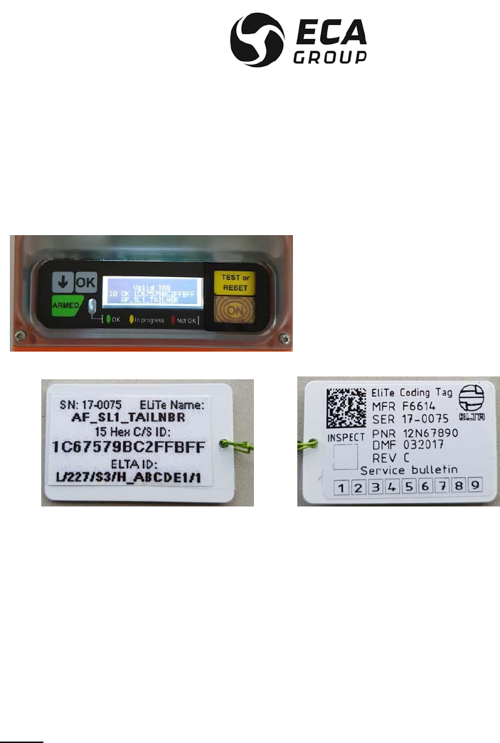
Documentation P/N: 15E64259 Rev A Page 28
Oct. 10/17
. Aircraft Registration Marking [Tail Number] (up to 7 characters),
Example of display on ELiTe TRANSMITTER LCD “AF_SL1_TAILNBR” stands for:
Automatic Fixed (AF) using Standard Location Protocol N° 1 [A/C 24 bit Address] for the A/C
registration Marking “TAILNBR”.
Corresponding Labels present on the relevant ELiTe
Coding Tag P/N 12N67890 S/N 17-0075
Definition of the available protocols:
. U1, User Protocol, A/C Registration Marking,
. U2, User Protocol, ELT serial number,
. U3, User Protocol, Operator Designator and ELT serial number,
. U4, User Protocol, A/C 24 bit Address,
. UL1, User Location Protocol, A/C Registration Marking,
. UL2, User Location Protocol, ELT serial number,
. UL3, User Location Protocol, Operator Designator and ELT serial number,
. UL4, User Location Protocol, A/C 24 bit Address,
. SL1, Standard Location Protocol, ELT serial number,
. SL2, Standard Location Protocol, Operator Designator and ELT serial number,
. SL3, Standard Location Protocol, A/C 24 bit Address,
NOTE: For Location Protocols in Automatic Fixed configuration, standard ARINC speed is “High”. If the
customer wishes to select ARINC speed “Low”, then the letter “L” is added after the protocol
selection giving UL1L, UL2L, UL3L, UL4L, SL1L, SL2L & SL3L.
(h)Miscellaneous characteristics in Automatic Fixed configuration
– Automatic activation level in accordance with EUROCAE ED-62A / RTCA DO-204A (G-switch
module on ELiTe AF-BRACKET, see APPENDIX D
activation direction is selectable (4 possible directions 0°, 90°, 180° & 270°, see Figure 12),
– Remote control capability:
ON/ARMED
TEST/RESET
ELiTe TRANSMITTER activation indicator.
– Provision for future “inflight activation” via an independent discrete input (ground).

Documentation P/N: 15E64259 Rev A Page 29
Oct. 10/17
NOTE: For the moment, a ground on this input will activate ELiTe TRANSMITTER as the G-Switch or
manual activation from remote control panel (no special transmission feature),
– Color is predominantly orange in conformity with the international distress code,
– Self-test, transmission of one 406.040 MHz burst, modulated with inverted frame synchronization
and three sweeps transmission on 121.5 MHz, automation to ARMED position on both the ELiTe
TRANSMITTER and Remote Control Panel),
– Any User, User Location & Standard Location COSPAS/SARSAT protocol available,
. ELT S/N
. A/C operator designator and S/N
. A/C 24 bits address
. A/C nationality and registration marking (not available for standard location protocol)
. TEST (not for operational purposes)
– Any country code available,
– Can operate in short or long COSPAS/SARSAT messages.
For long message, location data can be received from A/C ARINC 429 data bus (primary access), or
from internal GNSS complete receiver (backup solution),
– Independent COSPAS/SARSAT identification stored in a transferable ELiTe Coding Tag located on
ELiTe AF-BRACKET to ease maintenance on ELT,
– Dual frequencies 121.5 – 406.040 MHz antenna access. Primary is the external antenna 50 homs
BNC connector on ELiTe AF-BRACKET and secondary is the internal antenna inside ELiTe
TRANSMITTER in case of failure detection on primary access.
(i)Miscellaneous characteristics in Survival configuration
– Water sensor allows additional activation,
– Color, orange in conformity with the international distress code,
– Selt-test, transmission of one 406.040 MHz burst modulated with inverted frame synchronization
and three sweeps transmission on 121.5 MHz, automation to Armed position on the ELiTe
TRANSMITTER,
– Any User Location & Standard Location COSPAS/SARSAT protocol available for Survival
configuration,
. ELT S/N
. A/C operator designator and S/N
. A/C 24 bits address
. A/C nationality and registration marking (not available for standard location protocol)
. TEST (not for operational purposes),
– Any country code available,
– Operates in long COSPAS/SARSAT message.
Location data is received from internal GNSS complete receiver,
– Independent COSPAS/SARSAT identification stored in a transferable ELiTe Coding Tag located on
ELiTe S-BRACKET (or alternative ELiTe S-Bag) to ease maintenance on ELT,

Documentation P/N: 15E64259 Rev A Page 30
Oct. 10/17
3. DESCRIPTION OF THE ELiTe ELT AND OF THE AIRCRAFT COMPONENTS
A. General description
(1)The ELiTe ELT essentially consists of:
– an ELiTe TRANSMITTER beacon that includes:
• an internal 121.5 – 406.040 MHz dual frequency antenna,
• an internal GNSS complete receiver with antenna,
• a water sensor (fresh or salted water, only operational in Survival configurations),
• a battery pack,
• a keypad with LCD display,
• a three colored indicator LED,
• an RFID reader (for ELiTe Coding Tag data access),
• an ATA SPEC 2000 RFID passive label,
– labels,
– an ELiTe Coding Tag (for Cospas-Sarsat Identification),
– an ELiTe AF-BRACKET for AUTOMATIC FIXED configuration,
• Orientable G-Switch module,
• Female BNC 50 Ω external antenna access,
• Female 26 pins CANON D SUB HD for remote control panel, A/C data bus, +28 Vdc and discrete
input provision for inflight activation) connections,
• Location for ELiTe Coding Tag,
– an ELiTe S-BRACKET or ELiTe S-Bag for SURVIVAL configuration,
• Internal fixations foams,
• Location for ELiTe Coding Tag,
• Allows flame protection (per ED-62A/RTCA-DO-204A),
– an ELiTe Float for SURVIVAL configuration.
(2)The ELiTe Automatic Fixed (AF) basic aircraft components consists of:
– a remote control panel (cockpit),
– an external 121.5 – 406.040 MHz dual frequency antenna,
– an ARINC 429 access (when A/C Navigation Data input is required),
– a +28Vdc input (for Navigation Data input management, when required).
B. Detailed description
(1)The ELiTe TRANSMITTER (Ref Figure 20)
The ELiTe TRANSMITTER mainly consists of :
– a power supply module,
– an electronic assembly,
– a mechanical assembly (waterproof case).
– Keypad controls,
– LCD display,
– Three colored LED,
– Two Flash LED (8 bis),
– labels
Documentation P/N: 15E64259 Rev A Page 31
Oct. 10/17
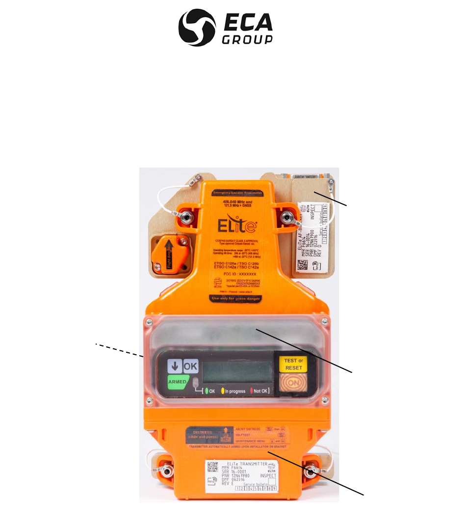
The front face of the ELiTe TRANSMITTER is equipped with the following components:
– a five buttons keypad (1, 5, 6, 7, 8)
– a three lines LCD display (3)
– a three colored LED indicator (4)
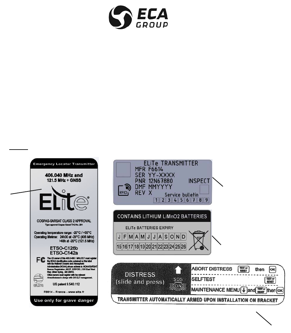
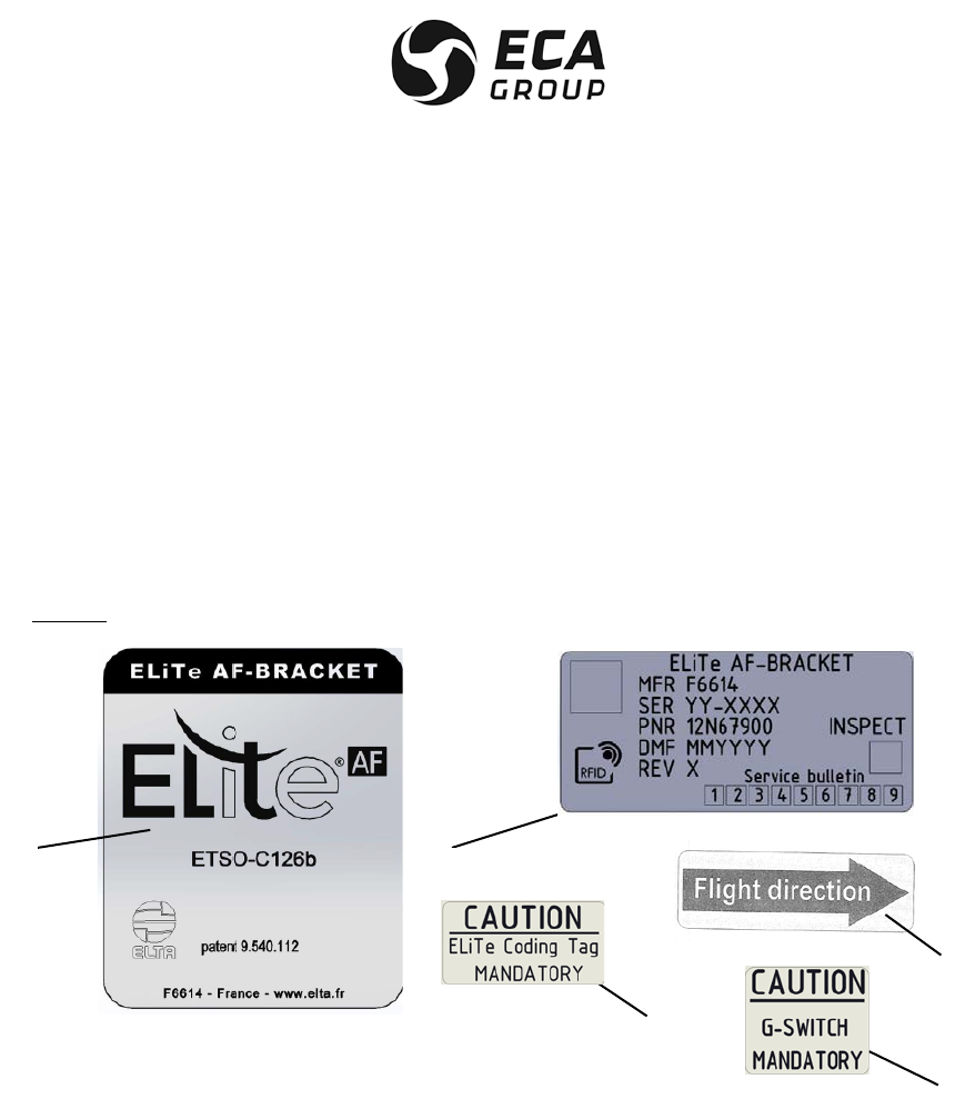
The labels are (Ref Figure 9):
General identification (1), PNR & SER (Part & Serial number) (2), battery expiry (3) and how to use (4):
NOTE: PNR & SER label is in accordance with SPEC 2000 (RFID Label).
Figure 9
ELiTe TRANSMITTER - Labels
(2) The ELiTe AF-BRACKET (Ref Figure 20)
The ELiTe AF-BRACKET mainly consists of:
– an electronic assembly,
– a mechanical assembly,
– labels,
– a BNC 50 homs connector (female),
– a Canon D SUB High Density connector (26 pins female),
– a spring loaded connector (16 pins male)
The front face of the ELiTe AF-BRACKET is equipped with the following components :
1
3
4
2
Documentation P/N: 15E64259 Rev A Page 32
Oct. 10/17
– an electrical D-SUB- high density 26 pins female connector (12) for connecting up to the aircraft
remote control panel and A/C ARINC 429 Data Bus with + 28 Vdc when required,
– a BNC female connector (11) for connecting up the external antenna,
– a 16 pins male spring loaded connector for connecting up ELiTe TRANSMITTER (14),
Additionally the AF-BRACKET supports
– a G-Switch module located on the right (10)
– a mechanical storage location for ELiTe Coding Tag (15)
The labels are (Ref Figure 10):
General identification (1), PNR & SER (Part & Serial number) (2), G-Switch module activation direction
(flight direction) (3), caution for actual presence of G-Switch module (4) and ELiTe Coding Tag (5) on
ELiTe AF-BRACKET:
NOTE: PNR & SER label is in accordance with ATA SPEC 2000 (passive RFID Tag).
Figure 10
ELiTe AF-BRACKET – Labels
3
1
2
4
5

Documentation P/N: 15E64259 Rev A Page 33
Oct. 10/17
(3)ELiTe Automatic Fixed (AF) aircraft components
CAUTION :THE REMOTE CONTROL PANELS AND EXTERNAL ANTENNA ARE LISTED IN THE
COSPAS-SARSAT ELITE TAC # (C/S APPROVAL). USE OF OTHER PART NOT LISTED IN THE TAC
MAY REQUIRE ADDITIONAL COSPAS-SARSAT APPROVAL TESTS AND UPDATE OF CURRENT
TAC#. IT ALSO MAY CANCEL THE ETSO C126B GRANTED. CONTACT ELTA FOR ADDITIONAL
ASSISTANCE.
(a)Remote control panel
The remote control panel integrated in the aircraft cockpit usually consists of :
– a TEST/RESET pushbutton,
– an ELT ON indicator light,
– a two-position ON/ARMED switch with safety cover (flip guard). The safety cover forces the switch to
ARMED position. This switch must always remain in ARMED position, except in the case of manual
distress triggering.
The ELiTe Automatic Fixed ELT is integrated in the aircraft as far AFT as possible and so it must be
connected to the remote control panel. This remote control panel enables ELiTe TRANSMITTER
operation to be forced to ON (remote manual activation), to be tested (TEST), the distress transmission
stopped and restored in standby or ARMED mode (RESET) in the event of an untimely triggering of the
ELT, from the aircraft cockpit.
(b)External antenna
An external antenna is recommended to be installed on the fuselage of the aircraft to maximize
transmission of the distress signal to the satellites as required by ICAO.
The cable length should remain as short as possible in order to keep the connection RF losses lower
than 1.5 dB at each frequency (121.5 & 406.040 MHz) and to reduce the probability of cable damage
during and after the crash.

Documentation P/N: 15E64259 Rev A Page 34
Oct. 10/17
4. INSTALLATION OF THE ELiTe Automatic Fixed configuration
A. General
WARNING: ELITE TRANSMITTER CONTAINS NON RECHARGEABLE LITHIUM MANGANESE DIOXIDE
BATTERIES. IT SHALL NOT BE INSTALLED IN THE COCKPIT.
System security and reliability obviously depends on the standard of installation.
In order to ensure installation of the highest standard, the installation operations must be:
– performed in conformity with this document,
– performed in compliance with the current applicable regulations: CS, FAR or equivalent regulations
– performed by qualified personnel,
– performed so that :
. the aircraft's structural integrity is not affected,
. it will not hinder the pilot in normal position,
. it will not cause any damage in the event of an accident,
. it will not prevent or modify operation of the other safety systems.
If in doubt, contact the aircraft manufacturer or its representative,
. it will not degrade the ELiTe ELT performances described in DDP N° 16E24025 (Automatic Fixed),
– inspected by representative authority.
Special care should be taken in order to lower the risk of rupture of the RF cable between external antenna
and ELiTe AF-BRACKET due to vibration, shocks, flame.
B. Installation of ELiTe (AF) on the aircraft (Ref. Figure 11)
The ELiTe AF-BRACKET shall be installed as far AFT as possible in order to maximize the probability of ELT
survival in case of crash.
It Shall be installed on the primary structure of the A/C and shall not damp the crash sensor (G-Switch).
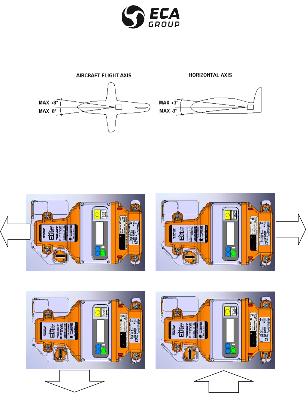
The G-Switch module DIRECTION OF FLIGHT must be parallel with the aircraft flight axis as indicated by
the G-Switch module's label. The G-Switch module direction and the A/C forward/aft directions must be
respected to ensure correct acceleration sensor (G.switch) operation (See Figure 11).
NOTE : An angle of up to ± 8° from the aircraft flight axis could be allowed.
An angle of up to ± 3° from the aircraft horizontal axis could be allowed.
Documentation P/N: 15E64259 Rev A Page 35
Oct. 10/17
Figure 11
Tolerances on the Axis for Installation of the ELiTe ELT (AF)
The ELiTe can be installed in any position (normal, upside down, right side, left side) with respect with the G-
Switch activation direction stated on Figure 12.
The G- Switch module of the ELiTe AF-BRACKET can be installed in four positions (90° step, see Figure 12). The
G-Switch activation direction is indicated by an arrow on the G-Switch module.
Figure 12
Automatic activation direction selection for ELiTe Automatic Fixed configuration
AIRCRAFT
FRONT
AIRCRAFT
FRONT
AIRCRAFT
FRONT
AIRCRAFT
FRONT
Documentation P/N: 15E64259 Rev A Page 36
Oct. 10/17
The fixation holes are part of ELiTe AF-BRACKET. Drilling pattern is the same as previous ADT 406 ELT.
The presented four possible solutions of G-Switch module on the top of the ELiTe AF-BRACKET are suitable
for A/C operation and are in accordance with EUROCAE ED-62A & RTCA DO-204A specifications.
These solutions will ease the installation of the ELiTe Automatic Fixed especially for retrofit application.
NOTE: The screens on display may be turned by 180° if required (through “maintenance” menu. Press at
the same time the “arrow” and “TEST or RESET” button on keypad and select the relevant control.
Validate by OK.
NOTE: For Helicopter installation the operator must verify with the local Airworthiness Authority for specific
installation instructions. Usually for the helicopter installation we recommend a 45° down inclination
(ELT G-Switch module direction indicated by “AIRCRAFT FRONT”) in order to take into account both axis X
(translation) and Z (vertical).
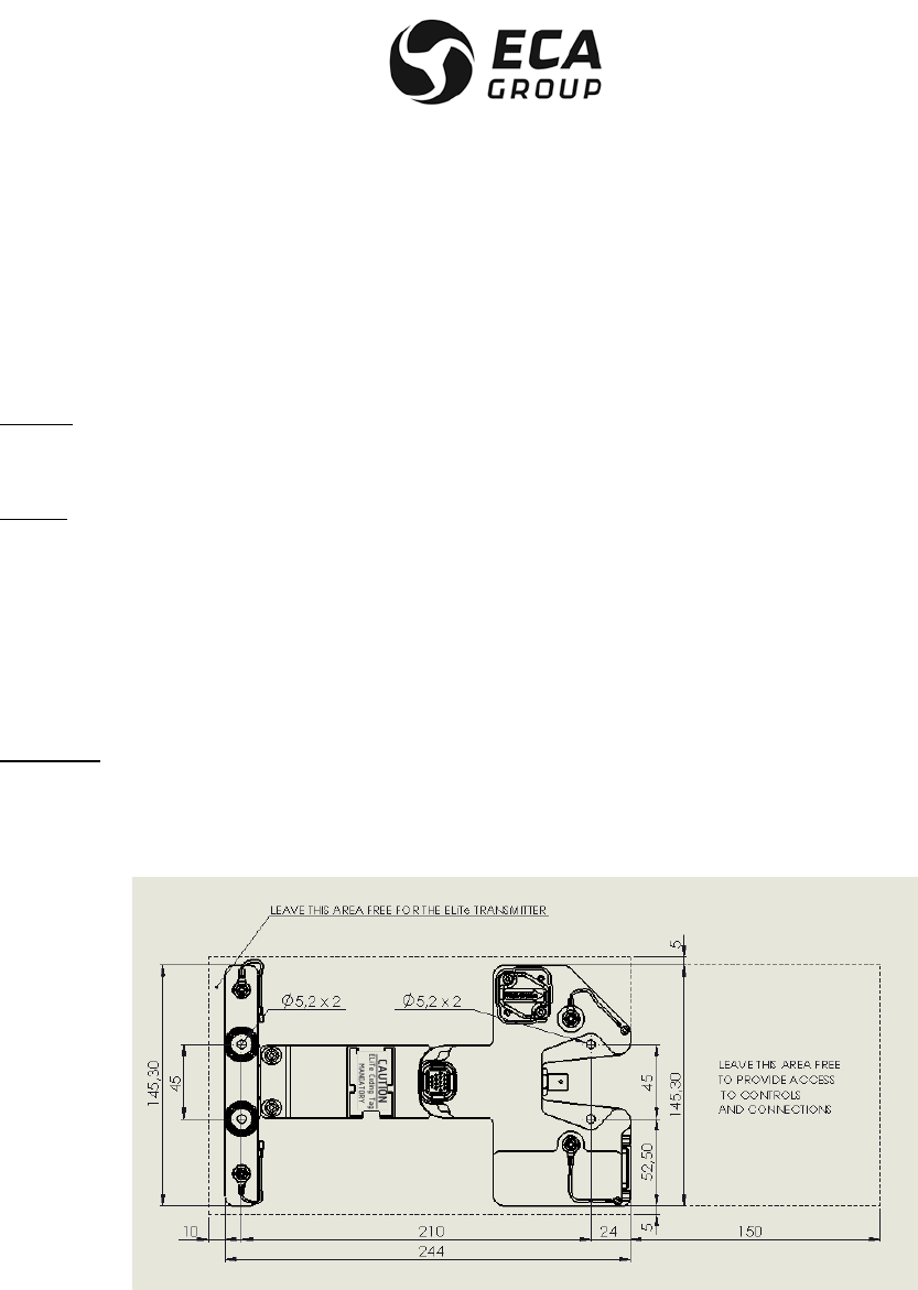
Attach the ELiTe AF-BRACKET to the fuselage of the aircraft by means of four M4 bolts in the four 5 mm
diameter holes at the corners of a 210 mm x 45 mm rectangle drilled in ELiTe AF-BRACKET. Particular care
must be taken with this attachment. Standard industry means must be used to lock the screws. Use flat
washer in order to avoid paint damage.
CAUTION : THIS ELT SHALL BE FIXED ON THE PRIMARY A/C STRUCTURE FOR CORRECT G-
SWITCH OPERATION DURING THE CRASH.
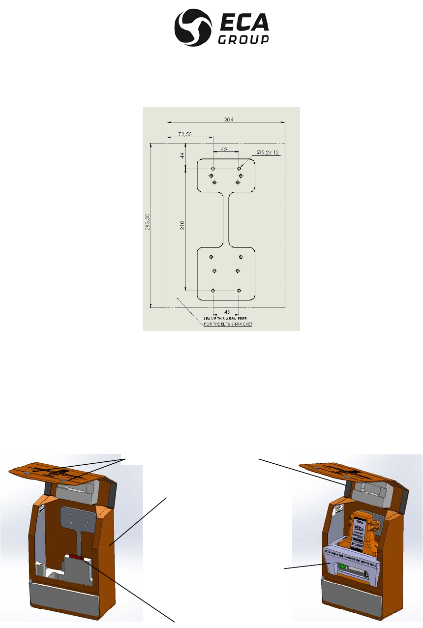
The Figure 13 shows the drilling pattern dimensions and determine the required area to access ELiTe
controls, connectors and space for ELiTe TRANSMITTER installation on ELiTe AF-BRACKET.
Figure 13
Installation of the ELT ELiTe ELT AF
(Automatic Fixed configuration)
- Drilling Pattern Dimensions

Documentation P/N: 15E64259 Rev A Page 37
Oct. 10/17
C. External antenna installation
ELTA recommend to use P/N 31908 (antenna model 2632-82 manufactured by COBHAM [formerly
CHELTON]) for high speed A/C or P/N 28592 (antenna model 1327-82 manufactured by CHELTON) for low
speed A/C.
Other external antenna may be used but some additional Cospas-Sarsat approval tests shall need to be
performed in order to amend the current Type Approval Number (TAC #). Contact ELTA or one of its
approved agents to check if the antenna can be used with this ELT model.
The external antenna must be installed on the upper part of the fuselage, as far AFT as possible.
Particular care must be taken with this attachment. Standard industry means must be used to lock the
screws.
The contact surface should be reinforced to prevent the antenna from tearing away at high speeds.
The cable used shall be of a high quality with very low losses.
RG 142 cable type, or equivalent, is recommended. ELTA recommends length lower than 2 meters lowering
the risk of rupture in case of crash. Cable RF losses shall remain lower than 1.5 dB.
When the coaxial cable is installed and the connectors mated, each end should have some slack in the
cable.
NOTE: FAA AC 43.13-1b recommends a minimum bend radius of 6 times the outer diameter of coaxial
cable.
The cable should be secured loosely to aircraft structures for support and protection.
Application of fire sleeves meeting the requirements of SAE AS1072 around the coaxial cable is
recommended.
Coaxial cable connecting the Antenna to the ELT Antenna installation should not cross aircraft production
breaks.
Connect the connector to the antenna and to the “external antenna. access” on ELiTe AF-BRACKET (BNC
connector).
D. Remote Control Panel installation
The ELiTe Automatic Fixed ELT can be remotely controlled by using a remote control panel installed in the
cockpit of the aircraft.
We are using “current loop” for the detection of the Remote Control Panel actions (toggle switch and push
button), so cable length of this link is not an issue. By experience cable up to 200 meters remains fully
operational and do not require grounded cable. This link requires 4 AWG 22 or AWG 24 wires.
The only limitation for this application is the DC current drained from the pin 6 (RCP_ALIM) of the ELiTe AF-
BRACKET CANON D-SUB 26 pin HD connector that shall remain lower than 15 mA.
Refers to Figure 14 for wiring details.
Documentation P/N: 15E64259 Rev A Page 38
Oct. 10/17
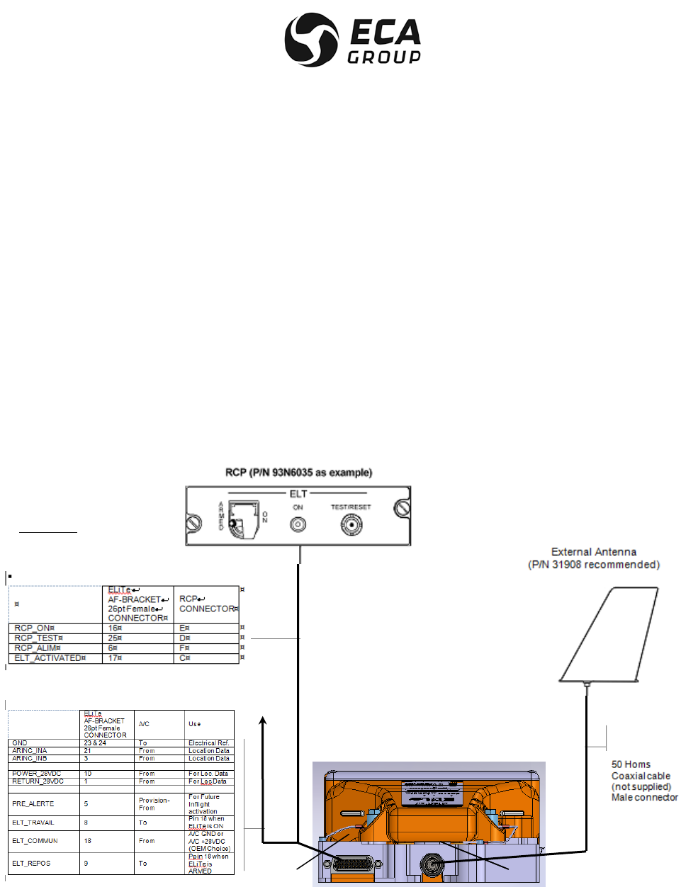
E. ELiTe peripherals connection diagram
The following simplified diagram shows the wiring between the ELiTe AF-BRACKET and its peripherals:
– The Remote Control Panel (in cockpit) identified as "RCP",
– The External Antenna",
– The connection to A/C Data Bus and +28 Vdc.
The External Antenna is connected to the ELiTe AF-BRACKET BNC female connector (1).
ELTA recommend to use RADIALL connector type R141 083 000 W (or equivalent).
The RCP - A/C Data Bus +28Vdc are connected to the ELiTe AF-BRACKET high density 26 pins female
Sub-D connector (2).
ELTA recommend to use a connector and backshell allowing to match ELiTe AF-BRACKET connector
ELTA recommend to use DEUTSCH connector type 8525-16R 14B19-SNH-002 (or equivalent) to match
ELTA RCP connector.
To From
A/C
Figure 14
ELITE Beacon Installation – Wiring Diagram
1 1
2
CAUTION :
Current consumption on
« RCP_ALIM » wire shall
remain lower than 15 mA.

Documentation P/N: 15E64259 Rev A Page 39
Oct. 10/17
F. Installation and configuration of the ELiTe Automatic Fixed (Ref. Figure 14)
– Connect the external antenna cable to the ELiTe AF- BRACKET BNC connector,
– Switch the Remote Control ON/ARMED lockable toggle switch to "ARMED" on remote control panel,
– Connect the remote control unit cable to the ELiTe AF- BRACKET CANON D SUB connector and lock it,
– Connect the remote control unit cable rear of the remote control panel and lock it performed by qualified
personnel,
– Connect the A/C Data Bus & 28 Vdc (if present),
– Install ELiTe Coding Tag on its ELiTe AF-BRACKET location. This installation is mandatory for correct
ELiTe ELT operation.
After correct installation of the ELiTe Coding Tag, it shall be attached to the A/C by means of the metallic
strap in order to keep on board A/C the Cospas-Sarsat identification information related to the installed ELT.
So these information will remain in the A/C upon transmitter exchange (for overhaul process as example).
Install and fix ELiTe TRANSMITTER on ELiTe AF-BRACKET by means of the four captive screws applying
1.6 N.m torque on each with a 9/32 wrench. ELiTe TRANSMITTER will be switched to ARMED automatically
and will display the relevant C/S ID code read from ELiTe Coding Tag; the system is ready for use.
CAUTION : ON INITIAL INSTALLATION OR INTALLATION ON DIFFERENT ELITE AF-BRACKET IT IS
ESSENTIAL TO ENSURE THAT ELITE TRANSMITTER DISPLAYS A 15 HEX ID THAT
MATCHES THE HEX ID OF THE ATTACHED ELITE CODING TAG.
CAUTION : AS SOON AS THE BEACON IS IN ARMED POSITION IT CAN BE AUTOMATICALLY
ACTIVATED BY THE INTERNAL G-SWITCH.
5. INSTALLATION OF THE ELiTe Survival configuration
A. General
WARNING: ELITE TRANSMITTER CONTAINS NON RECHARGEABLE LITHIUM MANGANESE DIOXIDE
BATTERIES (LiMNO²). IT SHALL NOT BE INSTALLED IN THE COCKPIT.
System security and reliability obviously depends on the standard of installation.
In order to ensure installation of the highest standard, the installation operations must be:
– performed in conformity with this document,
– performed in compliance with the current regulations,
– performed by qualified personnel,
– performed so that :
. the aircraft's structural integrity is not affected,
. it will not cause any damage in the event of an accident,
. it will not prevent or modify operation of the other safety systems.
If in doubt, contact the aircraft manufacturer or its representative,
– inspected by representative authority.

Documentation P/N: 15E64259 Rev A Page 40
Oct. 10/17
B. Installation of ELiTe (S) on the aircraft.
There is no special installation requirement.
Usually this type of Survival ELT is installed close to one exit door in order to allow easy access to cabin
crew in case of emergency evacuation.
For this type of use the ELiTe TRANSMITTER shall be equipped with ELiTe Float.
CAUTION : TRYING TO SLIDE ELITE FLOAT ON ELITE TRANSMITTER FROM TOP (INTERNAL
ANTENNA) TO BOTTOM (BATTERY PACK) WILL DAMAGE IT.
CAUTION : DO NOT PULL OR REMOVE THE LANYARD FROM THE FLOAT, THIS LANYARD SHALL
ONLY BE USES TO SECURE THE TRANSMITTER IN A DISTRESS CONDITION.
ELiTe Float shall be slide on ELiTe TRANSMITTER from bottom (Battery Pack) to top (internal antenna) and
is naturally locked on it (see Figure 15).
Figure 15
ELiTe Float Installation Process
When equipped in its final float position (see Figure 16) ELiTe TRANSMITTER can operate in various
conditions:
• Floating (like an EPIRB),
• Put on ground (like a PLB)
• Or insulated from any ground plane (held by a survivor).
NOTE: While floating the water sensor constituted by two screws of ELiTe TRANSMITTER is immerged
authorizing the additional water activation of ELiTe TRANSMITTER.
NOTE: The design of our water sensor require a complete immersion (DC current detection) for several
seconds, so moisture or non-permanent presence of water (splash) will not activate ELiTe TRANSMITTER.
NOTE: The water sensor is disable with the ELiTe TRANSMITTER is used in Automatic Fixed configuration.

Documentation P/N: 15E64259 Rev A Page 41
Oct. 10/17
Figure 16
ELiTe TRANSMITTER equipped with ELiTe Float
(1)Recommended installation
ELTA recommends using ELiTe S-BRACKET for such Survival configuration.
The fixation holes are part of ELiTe S-BRACKET. Drilling pattern is the same as previous ADT 406 S ELT.
NOTE: Lower internal ELiTe S-BRACKET foam (engraved with ELTA P/N 15P64038) can temporarily be
removed for easier metallic plate fixation.
Attach the ELiTe S-BRACKET in the A/C cabin of the aircraft by means of four M4 bolts through the four 5
mm diameter holes at the corners of a 210 mm x 45 mm rectangle drilled in ELiTe S-BRACKET. Particular
care must be taken with this attachment. Standard industry means must be used to lock the screws. Use flat
washer in order to avoid paint damage.
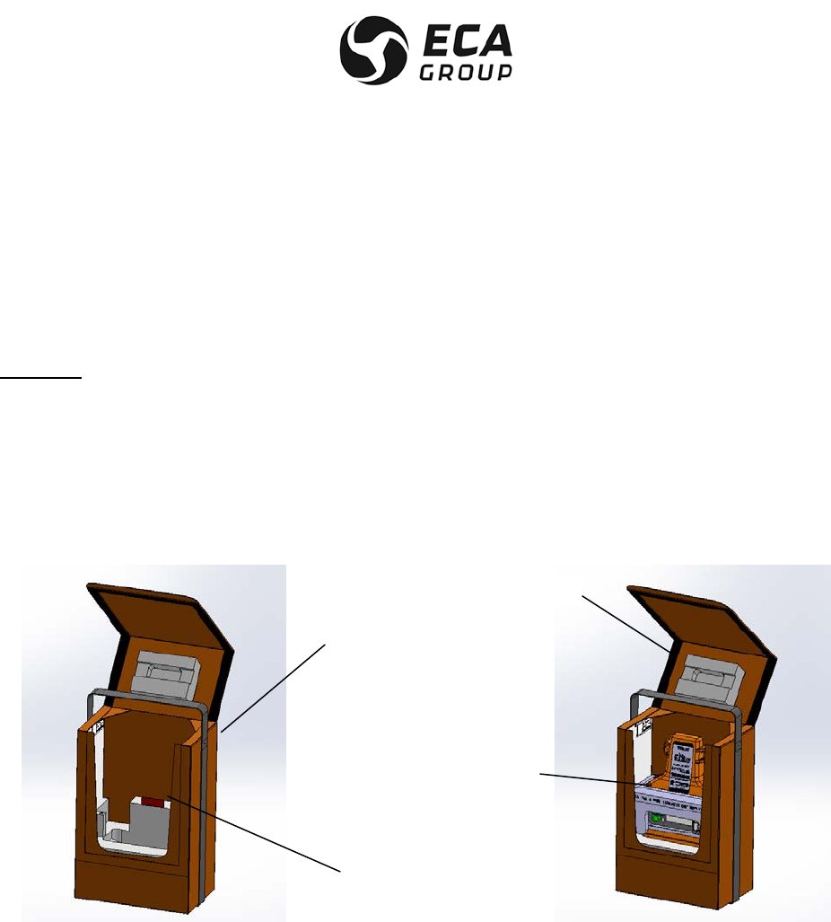
The Figure 17 shows the drilling pattern dimensions and determines the required area to access ELiTe
TRANSMITTER, ELiTe controls, and space for ELiTe S-BRACKET.
The overall volume for such installation is indicated in Figure 17
Documentation P/N: 15E64259 Rev A Page 42
Oct. 10/17
Figure 17
Installation of the ELiTe ELT S
(Survival configuration)
Drilling Pattern Dimensions
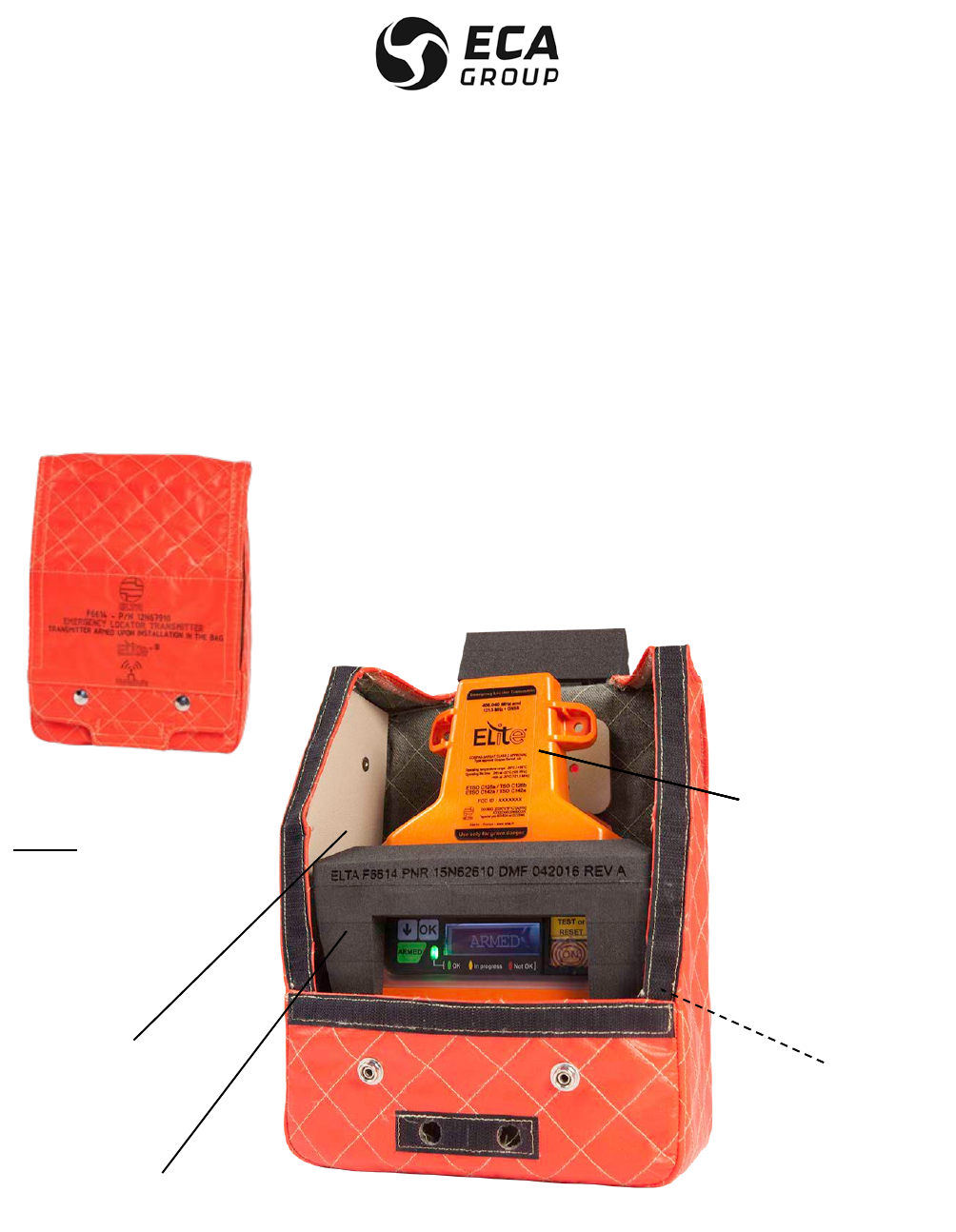
After correct installation of the ELiTe Coding Tag in ELiTe S-BRACKET (This installation is mandatory for
correct ELiTe ELT operation), it is recommended to attach it to one ELiTe S-BRACKET fixation screw by
means of the metallic strap in order to keep on board A/C the Cospas-Sarsat identification information
related to the installed ELT. So these information will remain in the A/C upon transmitter exchange (for
overhaul process as example).
Figure 18
ELiTe Survival - Recommended Configuration
ELiTe S-BRACKET
ELiTe Coding Tag
ELiTe TRANSMITTER
Equipped with
ELiTe Float
Velcro
Snap Fastener
Documentation P/N: 15E64259 Rev A Page 43
Oct. 10/17
ELiTe TRANSMITTER equipped with ELiTe Float is then slided in ELiTe S-BRACKET and ELiTe S-
BRACKET is closed and secured by Velcro and the two metallic snap fastener.
Impact of un-stowed objects to ELiTe parts must be avoided.
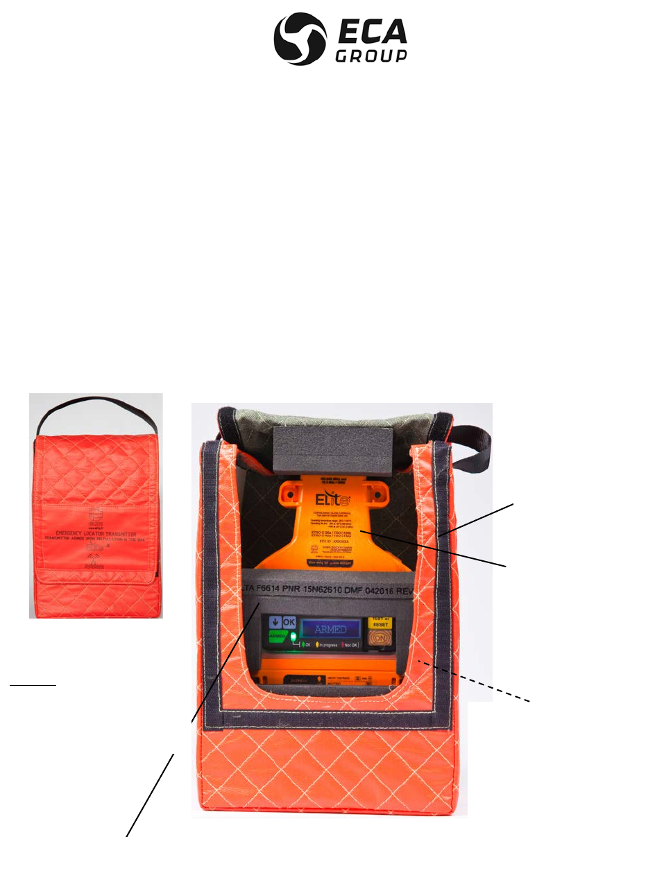
(2)Alternative Survival installation
ELTA can propose ELiTe S-Bag.
CAUTION : MEANS OF INSTALLATION SHALL NOT DEGRADE THE ELITE TRANSMITTER
PERFORMANCES AS DESCRIBED IN ELTA DDP N°16E24025 (SURVIVAL). IT MAY CANCEL
THE GRANTED ETSO C126b.
In this case there is no mean of fixation and the installer must secure it correctly in the cabin.
The overall volume for such installation is indicated in Figure 19.
After correct installation of the ELiTe Coding Tag in ELiTe S-Bag (This installation is mandatory for correct
ELiTe ELT operation), ELiTe TRANSMITTER equipped with ELiTe Float is then slided in ELiTe S-Bag and
ELiTe S-Bag is closed and secured by Velcro on the cover.
Impact of unstowed objects to ELiTe parts must be avoided.
Figure 19
ELiTe Survival - Alternative Configuration
(3)Auto-Armament of ELiTe TRANSMITTER (applies to both ELiTe S-BRACKET and ELiTe S-Bag)
ELiTe TRANSMITTER will be switched to ARMED automatically thanks to magnet located in bracket/bag
closing a reed relay contact inside the transmitter and will display the relevant C/S ID code read from ELiTe
Coding Tag; the system is ready for use.
ELiTe S-Bag
ELiTe Coding Tag
ELiTe TRANSMITTER
Equipped with
ELiTe Float
Velcro

Documentation P/N: 15E64259 Rev A Page 44
Oct. 10/17
CAUTION : ON INITIAL INSTALLATION OR INTALLATION ON DIFFERENT ELITE S-BRACKET / ELITE S-
BAG IT IS ESSENTIAL TO ENSURE THAT ELITE TRANSMITTER DISPLAYS A 15 HEX ID
THAT MATCHES THE HEX ID OF THE ATTACHED ELITE CODING TAG.
CAUTION : AS SOON AS THE BEACON IS IN ARMED POSITION IT CAN BE AUTOMATICALLY
ACTIVATED BY THE WATER SENSOR.
6. UTILIZATION OF THE ELITE ELT (Ref. Figure 20)
CAUTION : IN THE EVENT OF UNTIMELY ELT ACTIVATION, STOP THE ELT TRANSMISSION AS
DESCRIBED IN § E - RESTORING ELITE TRANSMITTER IN ARMED (STANDBY) - AND
INFORM THE CLOSEST SEARCH AND RESCUE (SAR) OR AIRPORT CONTROL TOWER
IMMEDIATELY.
A. General
ELiTe TRANSMITTER is getting its Cospas-Sarsat Identification message content from ELiTe Coding Tag
(RFID wireless connection).
ELiTe ELT states are:
– OFF, ELiTe TRANSMITTER cannot transmit any distress frequencies(operationally inactive),
– ARMED, normal position on board A/C. ELiTe TRANSMITTER waits a triggering signal (standby),
– ON (distress), ELiTe TRANSMITTER is transmitting the distress frequencies 406.040 MHz & 121.5 MHz,
– SELFTEST, ELiTe TRANSMITTER performs a self-test and transmits a single self-test message on
406.040 MHz and 121.5 MHz for 0.75 second (3 frequency sweep)
– RESET, ELiTe TRANSMITTER stops transmitting distress frequencies and is restored in ARMED (standby).
NOTE: ELiTe TRANSMITTER is automatically switched to ARMED upon its installation on
ELiTe AF-BRACKET, inside ELiTe S-BRACKET or inside ELiTe S-Bag.
NOTE: ELiTe TRANSMITTER shall be removed from ELiTe S-BRACKET or ELiTe S-Bag for correct
transmission operations.
ELiTe ELT can be activated in four (4) modes:
– Manually (valid for Automatic Fixed and Survival configurations). It includes remote control panel
activation from the cockpit(Automatic Fixed)
– automatically when the acceleration sensor (G-Switch) is triggered (Limited to Automatic Fixed),
– by the mean of a water sensor (limited to Survival)
– Inflight activation via a discrete independent input (provision for future evolution, so far this activation is
similar to remote control panel activation in term of ELT transmission behavior).
B. Typical Operational scenarios
ELiTe ELT shall be used in scenarios that are in accordance with the Cospas-Sarsat submission for Type
Approval and that have been tested in Cospas-Sarsat approved laboratory (part of the TAC#).
Documentation P/N: 15E64259 Rev A Page 45
Oct. 10/17
(1) For ELiTe ELT in the Automatic Fixed configuration ELiTe AF-BRACKET shall be connected to an external
antenna as indicated in Figure 14 with RF connection losses between 0.2 and 1.5 dB max.
Physical installation of the external antenna shall not degrade the antenna specification (VSWR and
radiation pattern).
It corresponds to the Configuration 6 “Antenna fixed to ground plane – ELT Like” as defined in Cospas-
Sarsat C/S T.007 specification.
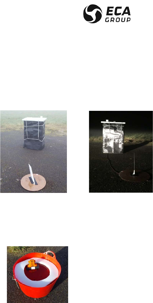
As examples, such test configurations in Approved Cospas-Sarsat laboratory are presented here under:
External high speed antenna (blade) External low speed antenna(rigid rod).
(2) For ELiTe ELT in the Survival configuration ELiTe TRANSMITTER equipped with ELiTe Float is using its
internal dual frequency antenna for distress signals transmissions. It can be used in three different
configurations. As examples such test configurations from Approved Cospas-Sarsat laboratory are
presented here under:
(a) Configuration 5 “Water ground plane – EPIRB like” as defined in Cospas-Sarsat C/S T.007
specification, ELiTe ELT is transmitting while floating on water.
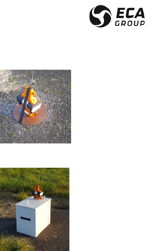
(b) Configuration 7 “Beacon on ground plane – PLB like” as defined in Cospas-Sarsat C/S T.007
specification, ELiTe ELT is transmitting while sitting on ground.
Documentation P/N: 15E64259 Rev A Page 46
Oct. 10/17
(c) Configuration 8 “Beacon above ground plane” as defined in Cospas-Sarsat C/S T.007 specification,
ELiTe ELT is transmitting while kept away from ground (insulated, no need of ground plane).
C. Automatic activation
CAUTION : IN CASE OF FALSE ACTIVATION OR TEST PURPOSE, THE OPERATOR SHALL STOP
THE ELT TRANSMISSION AS DESCRIBED IN § E -RESTORING ELITE TRANSMITTER IN ARMED
(STANDBY) WITHIN 50 S. AFTER THIS DELAY THE ELT WILL TRANSMIT ACTUAL DISTRESS
SIGNALS ON THE TWO AVAILABLE DISTRESS FREQUENCIES (406.040 & 121.5 MHZ).
The acceleration sensor has detected an impact sufficient to trigger it. The LCD display (3) indicates ELiTe
TRANSMITTER activation.
Upon automatic activation, the ELiTe TRANSMITTER performs one self-test (see §F Beacon self-test 6.F)
and displays self-test report on LCD (Figure 20 [3])
In this state, as long as the ELT is in operation, it sends the relevant distress frequencies.
D. Manual activations
Such manual activation can be achieved either by using ELiTe TRANSMITTER keypad (when accessible) or
remote control panel (when available).
There are three cases in which a distress signal may be triggered manually:

Documentation P/N: 15E64259 Rev A Page 47
Oct. 10/17
– the acceleration sensor (G-switch) has not been triggered but a distress signal must be sent (injured
passengers, aircraft out of operation ...),
– the aircraft is on the ground and must be evacuated.
– When a crash or ditching condition is imminent.
(1) First case: from the Remote Control Panel (Limited to Automatic Fixed configuration)
Raise the safety cover (guard) on the remote control panel (RCP) and place the switch in the ON position.
After two short blinks on RCP indicator, an automatic self-test sequence is performed (see § F(4) -Self-test
by mean of ON on remote control panel (RCP)).
CAUTION : IN CASE OF FALSE ACTIVATION THE OPERATOR SHALL STOP THE ELT TRANSMISSION
AS DESCRIBED IN § E -RESTORING ELITE TRANSMITTER IN ARMED (STANDBY) WITHIN 50 S.
AFTER THIS DELAY THE ELT WILL TRANSMIT ACTUAL DISTRESS SIGNALS ON THE TWO
AVAILABLE DISTRESS FREQUENCIES (406.040 & 121.5 MHZ).
This transmission state is permanently displayed on the Remote Control Panel indicator.
After about 50s delay, the ELiTe TRANSMITTER will transmit the two actual distress frequencies 121.5-
406.040 MHz.
In this state, as long as the ELT is in operation, it sends the relevant distress frequencies.
(2)Second case: from the ELiTe TRANSMITTER front panel (valid for Automatic Fixed & Survival
configurations)
– Slide the safety transparent cover SOS out of the ON button (1),
– Press and release the ON button (Figure 20[1]),
An automatic self-test sequence is performed (see § F(3) -Self-test by means of ON button on ELiTe
Keypad).
CAUTION : IN CASE OF FALSE ACTIVATION THE OPERATOR SHALL STOP THE ELT TRANSMISSION
AS DESCRIBED IN § E -RESTORING ELITE TRANSMITTER IN ARMED (STANDBY)-. WITHIN 50 S.
AFTER THIS DELAY THE ELT WILL TRANSMIT ACTUAL DISTRESS SIGNALS ON THE TWO
AVAILABLE DISTRESS FREQUENCIES (406.040 & 121.5 MHZ).
This transmission state is permanently displayed on the Remote Control Panel LED.
After about 50s delay, the ELiTe TRANSMITTER will transmit the two actual distress frequencies 121.5-
406.040 MHz.
In this state, as long as the ELT is in operation, it sends the relevant distress frequencies.
NOTE: For Survival configuration, ELiTe TRANSMITTER shall be removed from ELiTe S-BRACKET or
ELiTe S-Bag and put in service out of the A/C. It is recommended to attach it to a life raft or survivors in case
of ditching.
Documentation P/N: 15E64259 Rev A Page 48
Oct. 10/17
E. Restoring ELiTe TRANSMITTER in ARMED (standby)
In the event of a false maneuver or untimely operation, stops distress transmission.
The ELiTe TRANSMITTER is restored in its ARMED (standby) mode by pressing the “TEST/RESET”
pushbutton on the remote control panel or “TEST or RESET” button on ELiTe TRANSMITTER keypad..
NOTE: This control is not active if the remote control panel ON/ARMED switch is in ON position.
NOTE: When the manual activation had been done through the RCP, it shall be reset by the mean of RCP,
ELiTe TRANSMITTER “TEST or RESET” keypad button has no action.
NOTE: When the manual activation had been done through ELiTe TRANSMITTER “ON” keypad button, it
can be reset by the RCP or ELiTe TRANSMITTER “TEST or RESET” keypad.
NOTE : Stopping distress signal transmission by means of the remote control panel does not switch the
ELiTe TRANSMITTER OFF. It is restored in ARMED (standby) mode.
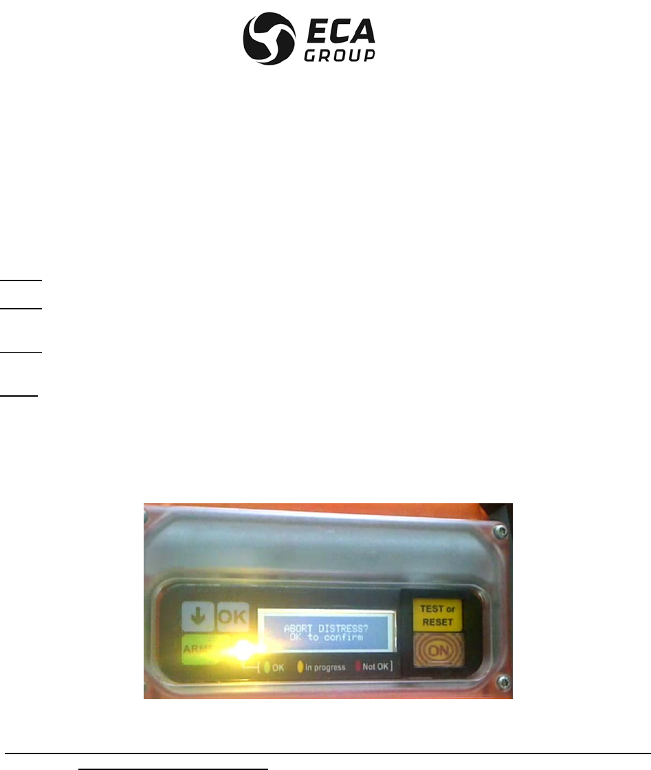
When “TEST or RESET” button on the keypad is used, ELiTe TRANSMITTER request a manual
confirmation.
The following message is displayed on LCD
– Press OK to confirm.
CAUTION : WITHOUT ACTION ON KEYPAD WITHIN 5 SECONDS, ELITE TRANSMITTER REMAINS IN
TRANSMISSION (DISTRESS).

Documentation P/N: 15E64259 Rev A Page 49
Oct. 10/17
F. Beacon self-test
CAUTION : ELTA RECOMMENDS TO PERFORM THE SELF-TEST WITHIN THE FIRST 5 MINUTES OF
ANY HOUR BECAUSE THE ELT IS SENDING 121.5 MHZ SIGNAL FOR ABOUT 0.75 S
(THREE 121.5 MHZ SWEEPS) DURING THIS SELF-TEST PROCESS (LIMITATION OF
FALSE ALERT).
The ELiTe TRANSMITTER is designed to perform a self-test either, from the remote control panel or from its
keypad.
Actual self-test incorporates transmission on 121.5 MHz for about 0.75s that can be listened on any VHF
receiver.
NOTE: After each activation, either manual or automatic, ELiTe TRANSMITTER performs a self-test before
entering in the distress mode.
While installed on any type of mounting bracket or bag ELiTe TRANSMITTER is automatically set to
ARMED.and reads the content of the relevant ELiTe Coding Tag located on/in ELiTe BRACKET or Bag.
ELiTe TRANSMITTER shall be in “ARMED” position in order to allow the self-test process.
Basically, the self-test result (report) is displayed on both ELiTe TRANSMITTER LCD display and on Remote
Control Panel (RCP) indicator when RCP is present (Automatic Fixed configuration).
RCP indicator gives a “summary” of the potential failures, failure detail is displayed on ELiTe
TRANSMITTER LCD display.
The actual Cospas-Sarsat Identification message (official 15 hex) is displayed on ELiTe TRANSMITTER
LCD display upon request (status) and for each self-test.
Self-test report includes “Failure” and “Warning” information’s. Failures are displayed first, followed by the
warning.
Failure corresponds to performances being out of specification that would need some short term
maintenance tasks, but ELiTe TRANSMITTER will operate and transmits distress signals in “a degraded
mode”.
Warning corresponds to information that would require customer attention in a short/medium term, such as
battery replacement expiry date coming soon.
Actual list of failure is (not listed per importance level):
• Impossibility to read ELiTe Coding Tag information,
• External antenna connection or failure,
• Software executable code corrupted,
• Low output power on 406.040 MHz - UHF
• Low output power on 121.5 MHz – VHF,
• Frequency not being 406.040 MHz – UHF – synthesis, PLL not locked,
• No +28 Vdc (Relevant for Automatic Fixed configuration requiring Lat & Long information from A/C
data bus)

Documentation P/N: 15E64259 Rev A Page 50
Oct. 10/17
Actual list of warning is (not listed per importance level):
• Total cumulative transmission above one (1) hour,
• Remaining battery capacity (x% of typical value),
• Maximum number of self-test reached,
• Next scheduled battery servicing date (from 0 to 4.5 calendar year starting at the date of the last
battery servicing),
• Battery replacement required in x month (from 4.5 and 5 calendar years starting at the date of the
last battery servicing),
• RCP fault,
• ELiTe AF-BRACKET fault,
• Maximum number (65) of GNSS self-test reached (relevant for Survival configuration)
Basically the following sequences are proposed with the messages displayed on ELiTe TRANSMITTER
LCD:
• Backlight duration for standard message is set to 3 seconds (power saving). Content of message
remaining displayed after backlight can be seen by using external source of light (such as flasklight
for example).
• Standard messages are displayed for 3 seconds,
• Confirmation messages are displayed for 5 seconds (ELiTe TRANSMITTER returns in its current
state if confirmation (OK) is not performed within these 5 seconds,
• The three colors LED (green, red, orange) can briefly blink (start of task) or be permanently
illuminated for 3 seconds (action/state confirmation).
Example of timing diagram about message display, blinking, illumination of three colors LED are presented
in APPENDIX C – TIMING DIAGRAM EXAMPLE for better understanding.
NOTE: When the self-test is performed on ELiTe TRANSMITTER alone (removed from any bracket or bag),
the report displayed on LCD will indicate “No valid Tag” and will display the content of the C/S ID issued
from its internal memory. Do not take care of this message. It will be corrected in near future with the
indication better related to “Missing ELiTe Coding Tag”.
NOTE: Even if the self-test report is negative, it will not block the activation of ELiTe TRANSMITTER
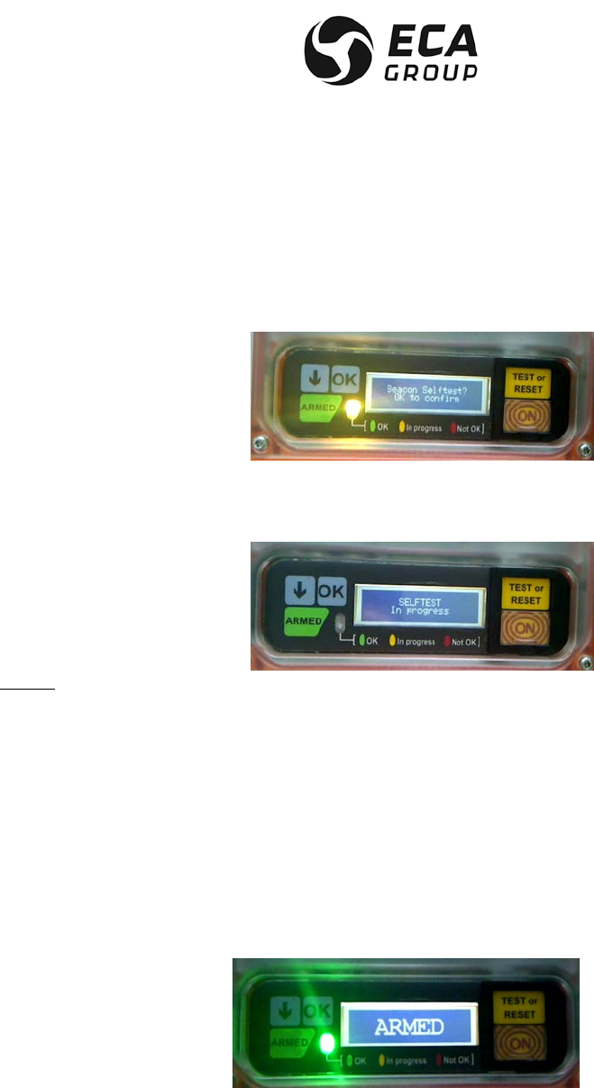
Documentation P/N: 15E64259 Rev A Page 51
Oct. 10/17
(1)Self-test by means of “TEST or RESET” button on ELiTe TRANSMITTER keypad.
Press “TEST or RESET” button for about 1 second.
The orange indicators blinks and the following confirmation message is displayed on LCD.
Press « OK » to confirm within 5 seconds
The following self-test message is displayed on LCD until the end of the self-test report.
NOTE: Backlight is active for 3 seconds only (power saving).
The orange indicators blinks seven time during the selftest process
• Positive self-test report is indicated by the green indicator illumination for 3 seconds and the
following message is displayed for 3 seconds:
“BEACON SELFTEST OK”.
Then the relevant C/S Identification is displayed for 3 seconds followed by the sequence of relevant
warning messages if any. Each warning message is displayed for 3 seconds, so the total duration depends
of the actual number of warning.
As a minimum the following message is displayed:
“WARNING Battery Capacity xx %” (xx equal the remaining capacity).
At the end of warning messages display the following message is displayed for 3 seconds along with the
green indicator:

Documentation P/N: 15E64259 Rev A Page 52
Oct. 10/17
• Negative self-test report is indicated by the red indicator illumination and the first failure encountered
message is displayed for 3 seconds:
“SELFTEST FAILED xxxxxx”, xxxxx is the relevant first failure occurring during the self-test process.
Then the other failure messages are individually displayed for 3 seconds each.
The red indicator remains illuminated while the failure messages are under display.
Then the relevant C/S Identification is displayed for 3 seconds followed by the sequence of relevant warning
messages if any. Each warning message is displayed for 3 seconds, so the total duration depends of the
actual number of warning.
As a minimum the following message is displayed:
“WARNING Battery Capacity xx %” (xx equal the remaining capacity).
At the end of the warning messages display, the following message is displayed for 3 seconds along with
the green indicator:
(2)Self-test by means of the remote control Panel (RCP)
The Remote Control Panel toggle switch ARMED/ON must be in ARMED position.
Press the TEST/ RESET for about 1 second.
Release the TEST/ RESET push button.
Two short blinks on RCP indicator confirms the initialization of the self-test process.
After about 10 seconds the selftest report is displayed on RCP indicator.
• Positive self-test report is indicated by the RCP indicator permanent illumination for 10 seconds.
• Negative self-test report is indicated by the RCP indicator blinking at different rate.
The rate of blinking clarifies the failure.
Two categories of failure are displayed in sequence (when present).
(a) The first category corresponds to failure related to ELiTe TRANSMITTER. Duration of this blinking
condition is 8 seconds. Operator just need to count the number of blinks:
10 blinks, the failure is related to the external antenna bad connection or External antenna
failure (bad VSWR)
20 blinks, the potential failure can be:
-> 406 MHz UHF power,
-> 121.5 MHz VHF power,
-> 406 MHz frequency,
-> No valid ELiTe Coding tag.
40 blinks, the potential failure is related to internal software code corrupted.
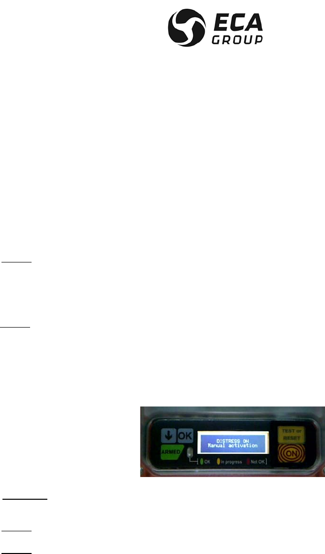
Documentation P/N: 15E64259 Rev A Page 53
Oct. 10/17
(b) The second category corresponds to failure related to location information obtained from the A/C
(Lat/Long). Duration of this blinking is 8 seconds. Operator just needs to count the number of blinks:
20 blinks, the potential failure is related to A/C data bus content: No ARINC labels 310 & 311
on A/C
40 blinks, the potential failure is related to A/C power supply availability: No A/C 28 Vdc
connection,
No blink (RCP indicator remains OFF-> 406 MHz frequency.
NOTE: During this self-test sequence, the information displayed on ELiTe TRANSMITTER LCD are the
same as for the self-test issued from “TEST or RESET” button on the keypad, including the display of the
warning messages if any.
(3)Self-test by means of ON button on ELiTe Keypad
NOTE: Not recommended by ELTA. It may create a false alert condition if it is not RESET in due time
(within 50s). ELTA recommends using the self-test process as described in (1) above.
On ELiTe TRANSMITTER, slide the safety transparent cover SOS out of the ON button
Press and release the ON button.
The green indicators blinks one time at the start of the self-test process
The following message is displayed on the ELiTe TRANSMITTER LCD.
CAUTION : OPERATOR SHALL RESET THE ELiTe TRANSMITTER WITHIN 50 s AFTER ACTIVATION
TO AVOID REAL DISTRESS TRANSMISSION (FALSE ALERT CONDITION).
NOTE: Backlight is active for 3 seconds only (power saving).
NOTE: There is no indication of the self-test detail failure on ELiTe TRANSMITTER LCD, message
“DISTRESS ON Manual activation” remains displayed throughout this process.

Documentation P/N: 15E64259 Rev A Page 54
Oct. 10/17
Self-test report is displayed on RCP indicator as follow:
• Positive self-test report is indicated by the RCP indicator permanent illumination for 10 seconds.
• Negative self-test report is indicated by the RCP indicator blinking at different rate.
The rate of blinking clarifies the failure.
Two categories of failure are displayed in sequence (when present).
The first category corresponds to failure related to ELiTe TRANSMITTER. Duration of this blinking
condition is 8 seconds. Operator just need to count the number of blinks:
10 blinks, the failure is related to the external antenna bad connection or External antenna
failure (bad VSWR)
20 blinks, the potential failure can be:
-> 406 MHz UHF power,
-> 121.5 MHz VHF power,
-> No valid ELiTe Coding tag.
40 blinks, the potential failure is related to internal software code corrupted.
No blink (RCP indicator remains OFF-> 406 MHz frequency,
The second category corresponds to failure related to location information obtained from the A/C
(Lat/Long). Duration of this blinking is 8 seconds. Operator just needs to count the number of
blinks:
20 blinks, the potential failure is related to A/C data bus content: No ARINC labels 310 & 311
on A/C
40 blinks, the potential failure is related to A/C power supply availability: No A/C 28 Vdc
connection,
(4)Self-test by mean of ON on remote control panel (RCP)
NOTE: Not recommended by ELTA. ELTA recommends using the self-test process as described in (2)
above.
Switch the RCP ON/ARMED toggle switch to ON
Two short blinks on RCP indicator confirms the initialization of the activation starting with a self-test
process.
NOTE: On ELiTe TRANSMITTER green indicator blinks two time and the following message is displayed
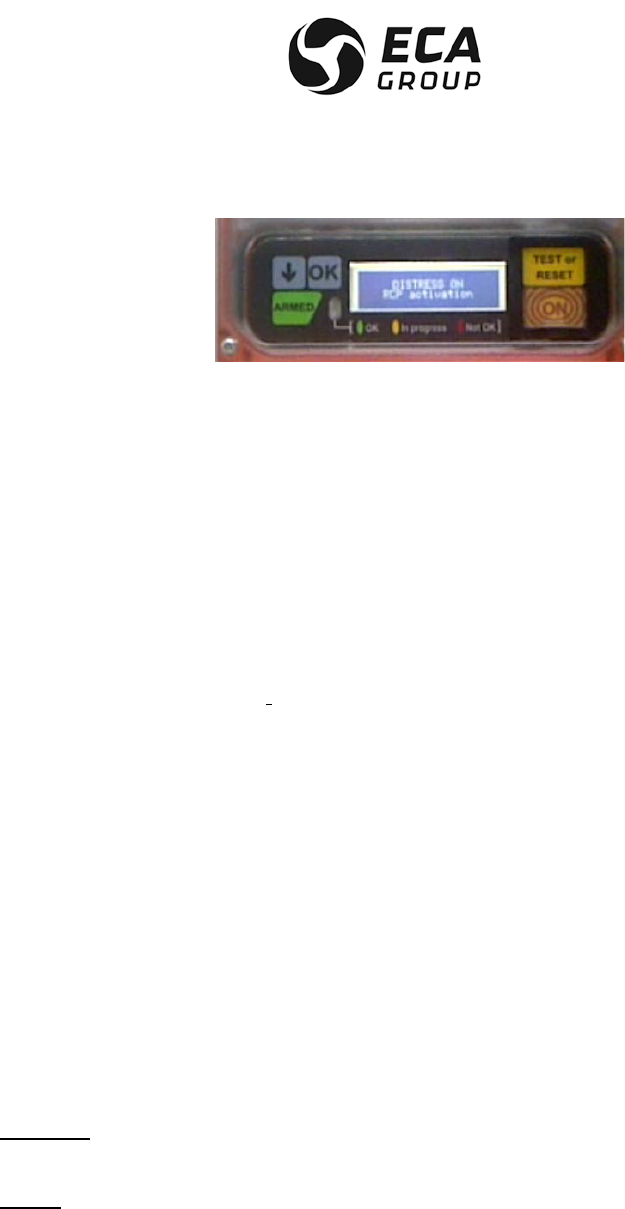
Documentation P/N: 15E64259 Rev A Page 55
Oct. 10/17
• Positive self-test report is indicated by the RCP indicator permanent illumination for 10 seconds.
• Negative self-test report is indicated by the RCP indicator blinking at different rate.
The rate of blinking clarifies the failure.
Two categories of failure are displayed in sequence (when present).
The first category corresponds to failure related to ELiTe TRANSMITTER. Duration of this blinking
condition is 8 seconds. Operator just need to count the number of blinks:
10 blinks, the failure is related to the external antenna bad connection or External antenna
failure (bad VSWR)
20 blinks, the potential failure can be:
-> 406 MHz UHF power,
-> 121.5 MHz VHF power,
-> No valid ELiTe Coding tag.
40 blinks, the potential failure is related to internal software code corrupted.
No blink (RCP indicator remains OFF-> 406 MHz frequency,
The second category corresponds to failure related to location information obtained from the A/C
(Lat/Long). Duration of this blinking is 8 seconds. Operator just needs to count the number of
blinks:
20 blinks, the potential failure is related to A/C data bus content: No ARINC labels 310 & 311
on A/C
40 blinks, the potential failure is related to A/C power supply availability: No A/C 28 Vdc
connection,
CAUTION : OPERATOR SHALL RESET THE ELiTe TRANSMITTER WITHIN 50 s AFTER
ACTIVATION TO AVOID REAL DISTRESS TRANSMISSION (FALSE ALERT CONDITION).
NOTE: There is no indication of the self-test detail failure on ELiTe TRANSMITTER LCD, message
“DISTRESS ON RCP activation” remains displayed throughout this process.

Documentation P/N: 15E64259 Rev A Page 56
Oct. 10/17
G. Switching ARMED automatically the ELiTe TRANSMITTER
When ELiTe TRANSMITTER is installed on ELiTe AF-BRACKET, in ELiTe S-BRACKET or in ELiTe S-Bag, it
is switched ARMED automatically.
Immediately after this installation ELiTe TRANSMITTER wake up and the ELTA initialization screen is
displayed on LCD for 3 seconds
Then the relevant C/S Identification is displayed for 3 seconds followed by the sequence of relevant warning
messages if any. Each warning message is displayed for 3 seconds, so the total duration depends of the
actual number of warning.
As a minimum the following message is displayed:
“WARNING Battery Capacity xx %” (xx equals the remaining capacity).
At the end of warning messages display the following message is displayed for 3 seconds along with the
green indicator:
H. Switching ARMED Manually the ELiTe TRANSMITTER
ELiTe TRANSMITTER can also be ARMED manually by pressing “ARMED” button on keypad.
Immediately the ELTA initialization screen is displayed on LCD for 3 seconds.
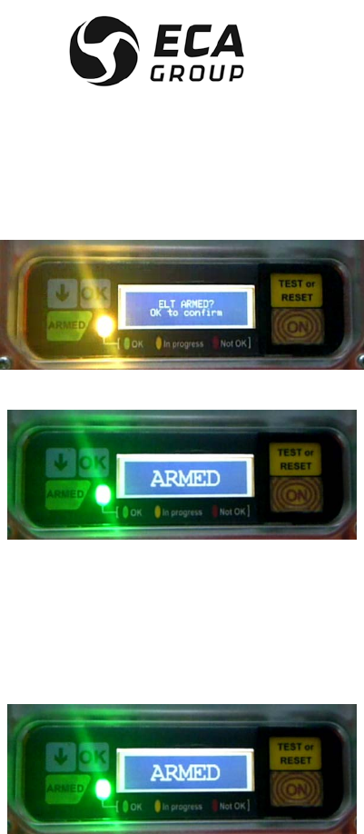
Documentation P/N: 15E64259 Rev A Page 57
Oct. 10/17
Then a confirmation message is displayed on LCD and the orange indicator blinks
Press OK to confirm,
ARMED message is displayed and the green indicator illuminates for 3 seconds
Then the relevant C/S Identification is displayed for 3 seconds followed by the sequence of relevant warning
messages if any. Each warning message is displayed for 3 seconds, so the total duration depends of the
actual number of warning.
As a minimum the following message is displayed:
“WARNING Battery Capacity xx %” (xx equals the remaining capacity).
At the end of warning messages display the following message is displayed for 3 seconds along with the
green indicator:

Documentation P/N: 15E64259 Rev A Page 58
Oct. 10/17
I. Switching OFF the ELiTe TRANSMITTER
After removal of ELiTe TRANSMITTER from ELiTe AF-BRACKET, ELiTe S-BRACKET or ELiTe S-Bag , it
remains in ARMED position.
For maintenance or transportation, ELiTe TRANSMITTER shall be switched OFF.
It will be restored automatically to ARMED upon installation on any type of bracket/bag after on.
Press “ARMED” button
A confirmation message is displayed on LCD, the orange indicator blinks
Press « OK » to confirm
OFF message is displayed on LCD and the red indicator illuminates for 3 seconds.

Documentation P/N: 15E64259 Rev A Page 59
Oct. 10/17
7. MAINTENANCE OF THE ELiTe ELT
CAUTION: FOR MAINTENANCE PURPOSED, DURING SHIPPING OR TRANSPORT OF THE ELT MAKE
SURE THAT ELITE TRANSMITTER IS IN “OFF” POSITION. THIS VERIFICATION WILL
AVOID FALSE ACTIVATION DURING TRANSPORT AND MANIPULATION IF THE ELT
REMAINS IN “ARMED”.
NOTE: There is no maintenance process on ELiTe S-BRACKET, ELiTe S-Bag & ELiTe Float (pure simple
mechanical parts). They are considered as “consumable” and shall be replaced by new part in case of
damage.
A. Beacon self-test
(1) ELiTe standard self-test (applicable to Automatic fixed and Survival configurations)
CAUTION : THE SELF-TEST PROCEDURE (PARAGRAPH 5.D.) MUST BE RESPECTED TO AVOID
UNTIMELY BEACON ACTIVATION.
The manufacturer recommends that a beacon self-test should be performed regularly. The highest rate is
one per month (65 for the typical 5 years battery replacement interval). Normally this task is added to other
periodic maintenance task such a “A” check. In any event the user must comply with the applicable
regulations in the country concerned governing the self-test period. In accordance with EUROCAE ED-62A
requirement the self-test needs to be performed at least once every six months.
A higher rate of self-test is possible but will reduce the standard 5 years battery servicing interval.
When the maximum number (65) of self-test is reached a ”Warning” is displayed on the LCD display.
(2) ELiTe TRANSMITTER GNSS self-test (limited to Survival Configuration)
The purpose of this GNSS self-test is to check the correct operation of the internal complete GNSS receiver.
It is not getting the actual location nor transmits any Cospas-Sarsat 406.040 MHz self-test message.
The GNSS self-test can only be triggered from ELiTe TRANSMITTER keypad. It is limited to maintenance
personnel and it is not accessible by immediate single action on the keypad.
The highest rate is one per month (65 for the typical 5 years battery replacement interval). A higher rate of
GNSS self-test is possible but will reduce the standard 5 years battery servicing interval.
CAUTION : THE GNSS SELF-TEST PROCEDURE SHALL BE PERFORMED UNDER UNOBSTRUCTED
VIEW OF THE SKY ALLOWING CORRECT GNSS SATELLITE SIGNALS RECEIPTION.
CAUTION : IT IS NOT RECOMMENDED TO PERFORM THE GNSS SELF-TEST FOR ELITE IN
AUTOMATIC FIXED CONFIGURATION AS THE RESULT WILL ALWAYS BE NEGATIVE DUE
TO THE IMPOSSIBILITY TO GET UNOBSTRUCTED VIEW OF THE SKY ALLOWING
CORRECT GNSS SATELLITE SIGNALS RECEIPTION INSIDE A/C STRUCTURE.
GNSS self-test is positive when the acquisition of the time from GNSS satellite constellation is achieved.
GNSS self-test is negative when the above time is not achieved within 4 minutes. Duration of the GNSS
self-Test is related to the time acquisition, up to 4 minutes.
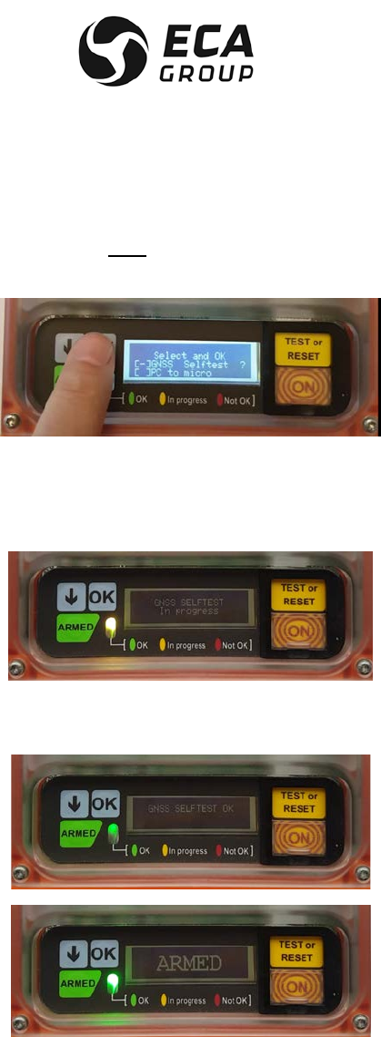
Documentation P/N: 15E64259 Rev A Page 60
Oct. 10/17
– Press at the same time on “ARROW” AND “TEST or RESET” buttons on ELiTe TRANSMITTER
keypad,
– Press one more time on “ARROW” for the selection of the GNSS self-test function,
– Press “OK” to confirm.
Orange LED is blinking and the following screen is displayed on ELiTe TRANSMITTER LCD, backlight is on
for 10 seconds, display remains for the entire duration of the GNSS self-test (can be seen using an
additional source of light).
If the acquisition of the time is possible (within 4 minutes max), the following screens are displayed in
sequence. Green LED is blinking.
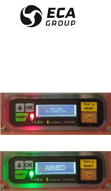
Documentation P/N: 15E64259 Rev A Page 61
Oct. 10/17
If the acquisition of the time is not possible, after 4 minutes the following screen is displayed and the red
LED illuminates for 5 seconds
Then ELiTe TRANSMITTER returns to ARMED and displays this screen for 3 seconds with green LED.

Documentation P/N: 15E64259 Rev A Page 62
Oct. 10/17
B. Maintenance periodicity table
Periodicity Operations Operator
5 years
Replacement of batteries
ELTA or approved agent/airline
The battery packs must be replaced:
– After use of the ELT in an emergency condition,
– After an inadvertent activation of unknown duration,
– When the cumulative time of the internal battery counter exceed one (1) hour as indicated by the self-
test report.
– On or before the proposed battery replacement date indicated on the expiry label stuck on the bottom
of the ELT and presented on ELiTe TRANSMITTER LCD after self-test..
C. Batteries replacement (ELiTe TRANSMITTER only)
CAUTION : THE BATTERY PACK SHALL BE APPROVED BY ELTA. IF OTHER PACK ARE USED ELTA
WILL CANCEL WARRANTY AND WILL REFUSE ANY RESPONSIBILITY ON THE
PRODUCT OPERATION / MISFUNCTION.
CAUTION : THE USE OF ANY TYPE OF BATTERY PACK OR CELL OTHER THAN THE ONE
APPROVED BY ELTA WILL INVALIDATE THE CURRENT ETSO APPROVAL GRANTED TO
THIS ELT.
CAUTION : THE BATTERIES UTILIZED SHALL NOT BE RECHARGED. DO NOT TRY TO OPEN,
RECHARGE, DISASSEMBLE, PUNCTURE OR THROW THEM IN A FIRE, AN EXPLOSION
MAY OCCUR.
Next battery servicing (expiry) date is indicated on a label stuck on the ELiTe lower case (battery pack
compartment)..
The existing battery packs must be replaced using the ELTA “battery servicing kit” P/N 17N20439 that
include all the necessary parts and consumable for a correct battery replacement. This task must be
performed by ELTA, an Approved ELTA service center or an ELTA approved trained final customer.
ELTA recommends that the ELiTe ELT should undergo a general overhaul when required and a complete
verification on its test and programming bench at this occasion.
Refer to ACMM 25-60-15 for detail of operation.
D. Batteries discarding
The batteries must be discarded in compliance with the applicable regulations in the country concerned.
NOTE : The type of battery used is not dangerous for the environment provided that it is completely
discharged.

Documentation P/N: 15E64259 Rev A Page 63
Oct. 10/17
Contact ELTA for getting additional discarding information if necessary.
ELTA will accept the battery packs for discard in France if the local discard process is not available in the
customer country.
E. Test to do at the time of a beacon return in workshop
Performs the following “Return to Service “tests described in CMM 25-60-15 :
– visual check,
– verification of acceleration sensor automatic triggering capability,
– verification of water sensor activation triggering capability,
– functional test of ELITE beacon,
– RF test on the operational frequencies 121.5 – 406.040 MHz.
F. ELiTe Coding Tag access for ELiTe Cospas-Sarsat Identification update.
For Cospas-Sarsat Identification update or change, ELiTe Coding Tag shall be replaced.
In order to do so, ELiTe TRANSMITTER shall be removed for correct access to the relevant ELiTe Coding
Tag. The current ELiTe Coding Tag shall be removed and shall be replaced by the new one containing the
new Cospas-Sarsat Identification. As indicated in chapters 4.F, 5.B(1) & 5.B(2) the presence of ELiTe
Coding Tag is mandatory.
After this ELiTe Coding Tag installation, ELiTe TRANSMITTER shall be re-installed (see chapters 4 & 5).
8. Glossary
– RCP, Remote Control Panel
– ELT, Emergency Locator Transmitter
– UHF, Ultra High Frequency
– VHF, Very High Frequency
– LCD, Liquid Cristal display
– PLL, Phase Locked Loop
– SAR Search And Rescue
– LEO, Low Earth Orbiting (satellites)
– GEO, Geosynchronous Orbiting (satellites)
– MEO, Medium Earth Orbiting (satellites)
– LUT Local User Terminal
– MCC, Mission Control Center
– RCC, Rescue Coordination Center
– EPIRB, Emergency Positioning Indicator Radio Beacon
– PLB, Personal Locator Beacon
– ITU, International Telecommunication Union
– IMO, International Maritime Organisation
– RTCA Radio Technical Commission for Aeronautics

Documentation P/N: 15E64259 Rev A Page 64
Oct. 10/17
–
Figure 20
ELT ELITE – Automatic Fixed – Detailed Description
Photos not contractual
1 – “ON” BUTTON 9 – INTERNAL DUAL FREQUENCIES
ANTENNA (Backup)
2 – BATTERY PACK COMPARTMENT 10 – ORIENTABLE G-SWITCH MODULE
3 – LCD DISPLAY 11 – EXT. ANT. BNC CONNECTOR (FEMALE)
4 – 3 COLOUR LED INDICATOR 12 – REMOTE CONTROL & A/C DATA BUS
CONNECTOR (SUB-D HD FEMALE 26 PINS)
5 – “ARMED” BUTTON 13 – ATA SPEC 2000 IDENTIFICATION LABEL
6 – “ARROW” BUTTON 14 – SPRING LOADED 16 PIN CONNECTOR
7 – “OK” BUTTON 15 – COSPAS-SARSAT IDENTIFICATION (RFID
TAG)
8 – “TEST or RESET” BUTTON 16 – METALIC STRAP
8 bis – FLASH WHITE LED 17 – CAPTIVE NUT (QTY FOUR)
5
2
3
4
6
7
12
13
14
15
16
1
8
9
10
11
17
8 bis
8 bis
13
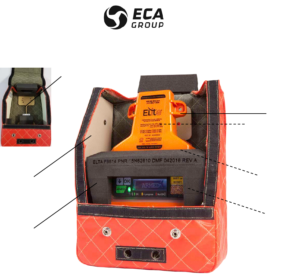
Documentation P/N: 15E64259 Rev A Page 65
Oct. 10/17
–
Figure 21
ELT ELITE – Survival with ELiTe S-BRACKET– Detailed Description
Photos not contractual
18 – ELiTe FLOAT
19 – ELiTe S-BRACKET
20 – ELiTe TRANSMITTER IN SURVIVAL CONFIGURATION (with water sensor activation capability)
21 – LOCATION OF INTERNAL DUAL FREQUENCIES ANTENNA (Primary,
Inside ELiTe TRANSMITTER)
22 – COMPLETE GNSS RECEIVER (Inside ELiTe TRANSMITTER)
23 – ELiTe Coding Tag (behind ELiTe Float, located in ELiTe S-BRABKET foam)
18
19
21
22
20
23
23
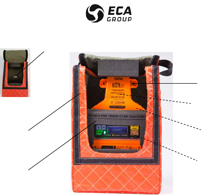
Documentation P/N: 15E64259 Rev A Page 66
Oct. 10/17
–
Figure 22
ELT ELITE – Survival with ELiTe S-Bag– Detailed Description
Photos not contractual
24 – ELiTe FLOAT
25 – ELiTe S-Bag
26 –ELiTe TRANSMITTER IN SURVIVAL CONFIGURATION (with water sensor activation capability)
27 – LOCATION OF INTERNAL DUAL FREQUENCIES ANTENNA (Primary,
Inside ELiTe TRANSMITTER)
28 – COMPLETE GNSS RECEIVER (Inside ELiTe TRANSMITTER)
29 – ELiTe Coding Tag (behind ELiTe Float, located in ELiTe S-Bag foam)
24
25
27
28
26
29
29

DOCUMENTATION P/N: 15E64259 REV A APPENDIX A page 1
Oct. 10/17
APPENDIX A
APPROVALS
COSPAS-SARSAT (TYPE APPROVAL CERTIFICATE)

DOCUMENTATION P/N: 15E64259 REV A APPENDIX A page 2
Oct. 10/17
DOCUMENTATION P/N: 15E64259 REV A APPENDIX A page 3
Oct. 10/17
JTSO 2C91a AND JTSO 2C126
APPROVAL
DOCUMENTATION P/N: 15E64259 REV A APPENDIX A page 4
Oct. 10/17

DOCUMENTATION P/N: 15E64259 REV A APPENDIX A page 5
Oct. 10/17
DOCUMENTATION P/N: 15E64259 REV A APPENDIX A page 6
Oct. 10/17
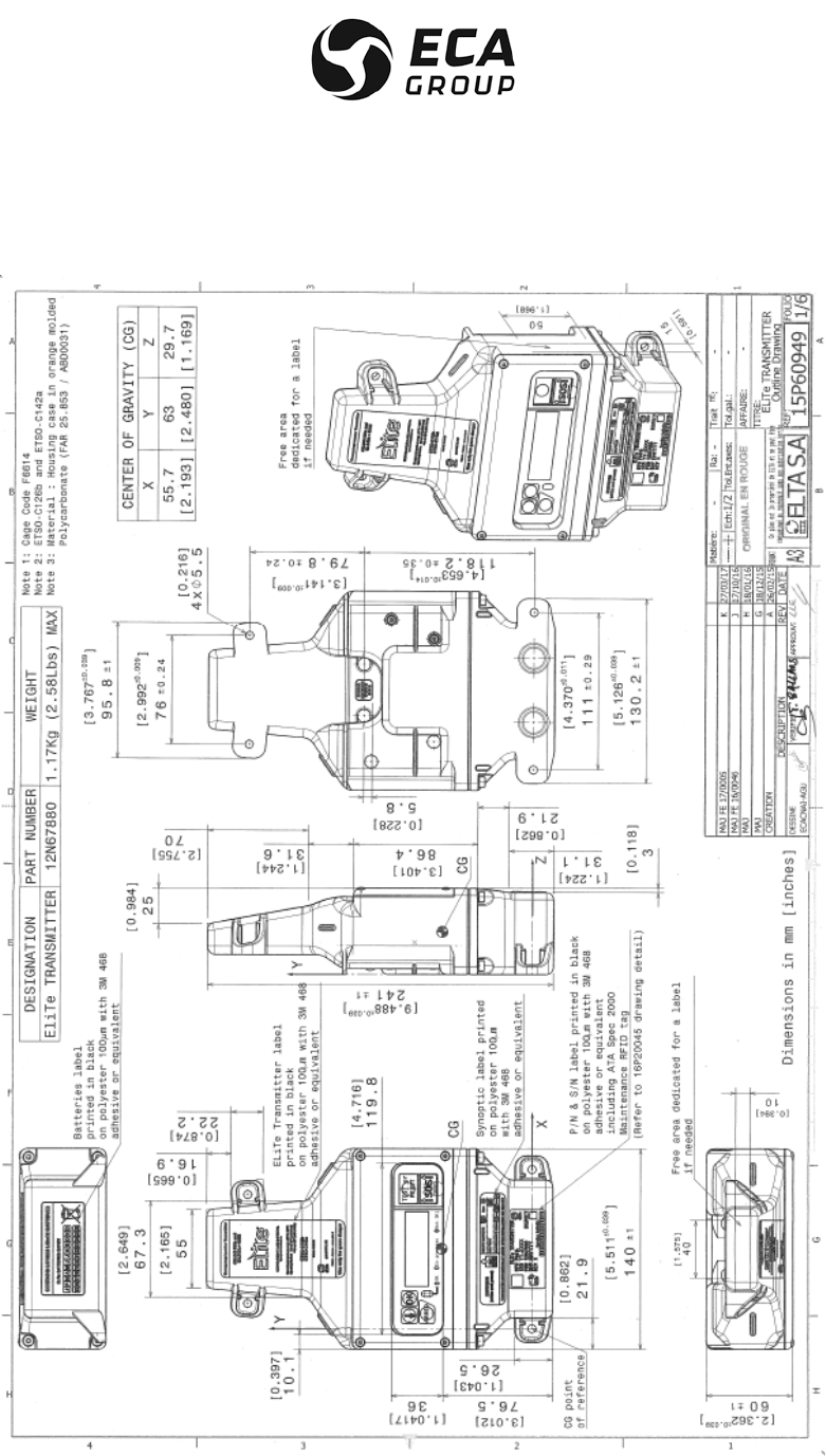
DOCUMENTATION P/N: 15E64259 REV A APPENDIX B page 1
Oct. 10/17
APPENDIX B
OUTLINE DRAWINGS
ELiTe TRANSMITTER OUTLINE DRAWING
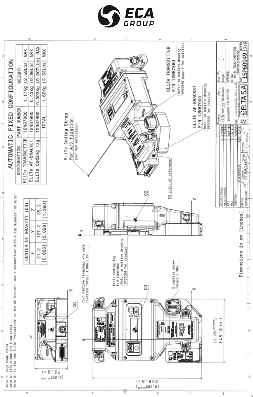
DOCUMENTATION P/N: 15E64259 REV A APPENDIX B page 2
Oct. 10/17
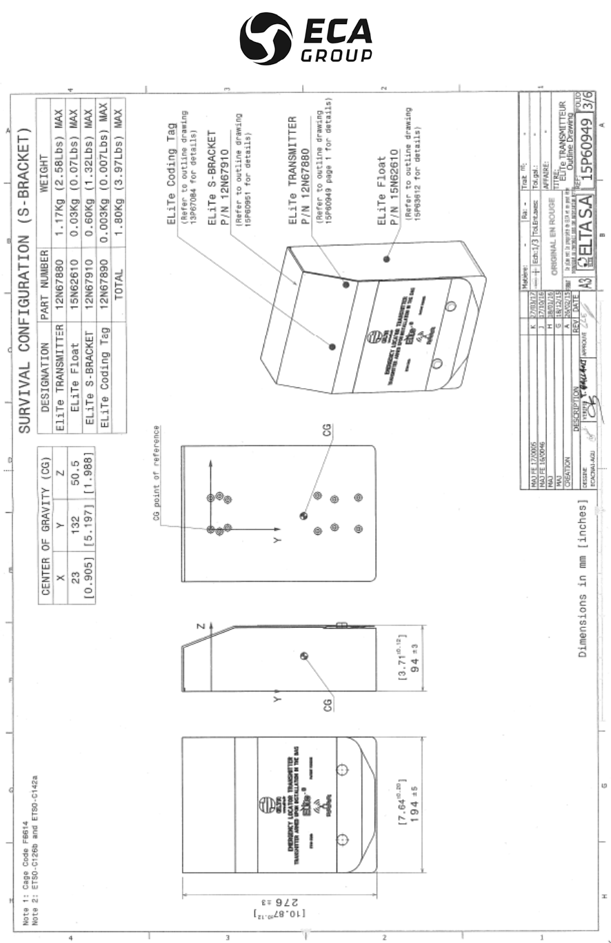
DOCUMENTATION P/N: 15E64259 REV A APPENDIX B page 3
Oct. 10/17
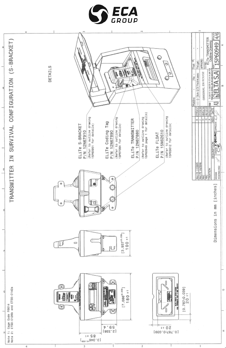
DOCUMENTATION P/N: 15E64259 REV A APPENDIX B page 4
Oct. 10/17
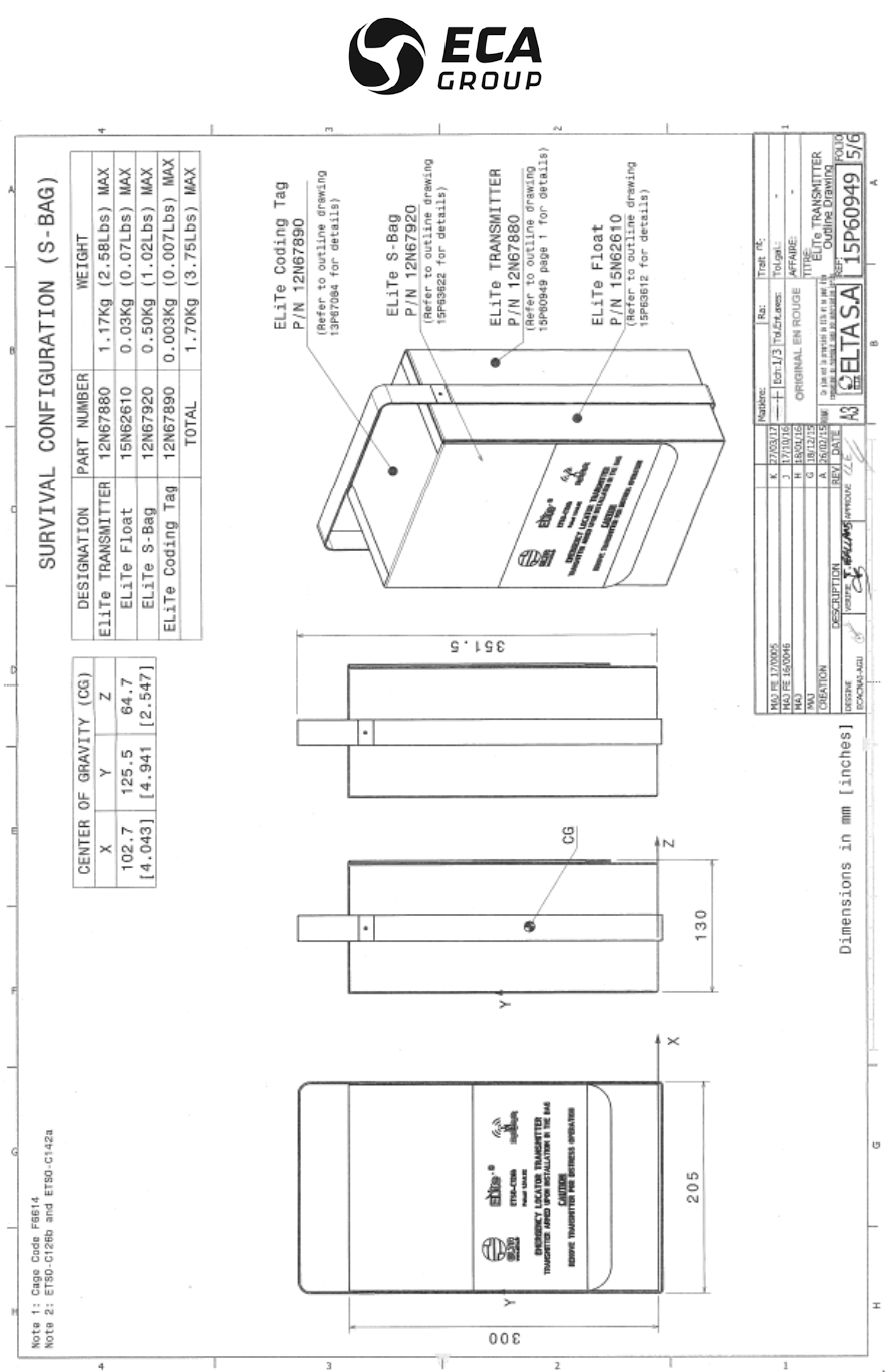
DOCUMENTATION P/N: 15E64259 REV A APPENDIX B page 5
Oct. 10/17
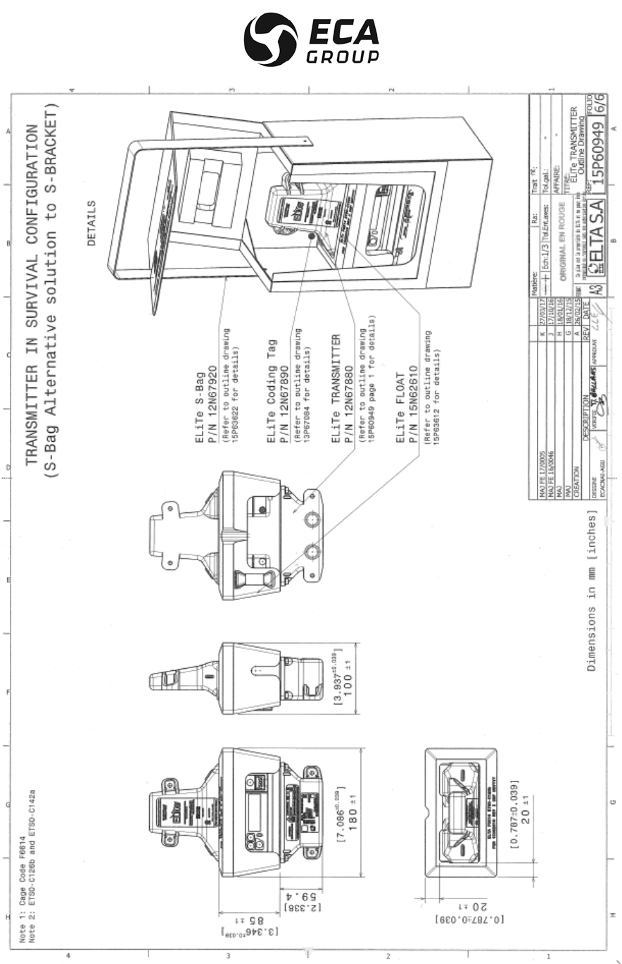
DOCUMENTATION P/N: 15E64259 REV A APPENDIX B page 6
Oct. 10/17
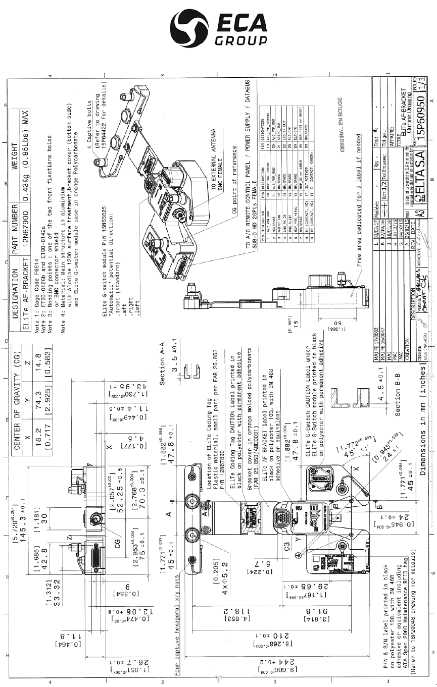
DOCUMENTATION P/N: 15E64259 REV A APPENDIX B page 7
Oct. 10/17
ELiTe AF-BRACKET OUTLINE DRAWING
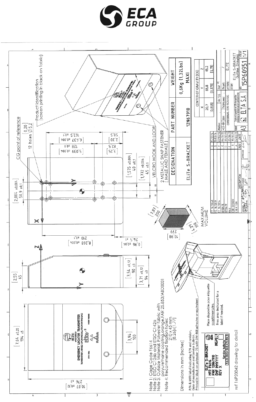
DOCUMENTATION P/N: 15E64259 REV A APPENDIX B page 8
Oct. 10/17
ELiTe S-BRACKET OUTLINE DRAWING
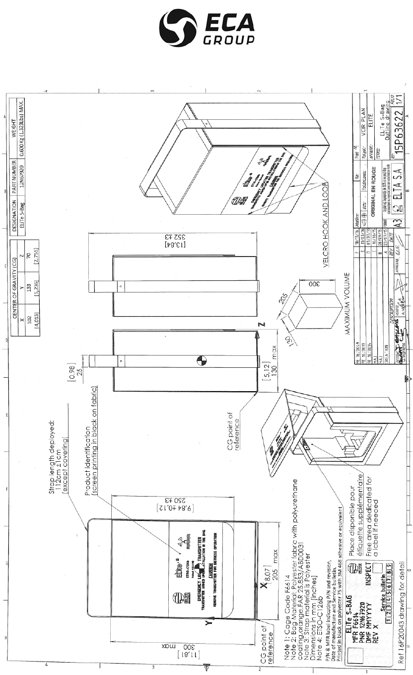
DOCUMENTATION P/N: 15E64259 REV A APPENDIX B page 9
Oct. 10/17
ELiTe S-Bag OUTLINE DRAWING
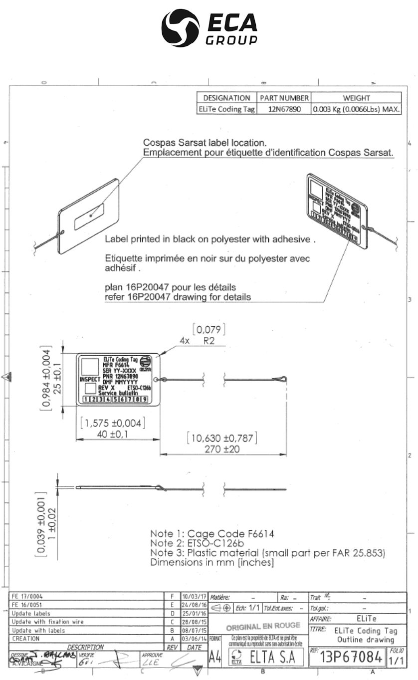
DOCUMENTATION P/N: 15E64259 REV A APPENDIX B page 10
Oct. 10/17
ELiTe Coding Tag OUTLINE DRAWING
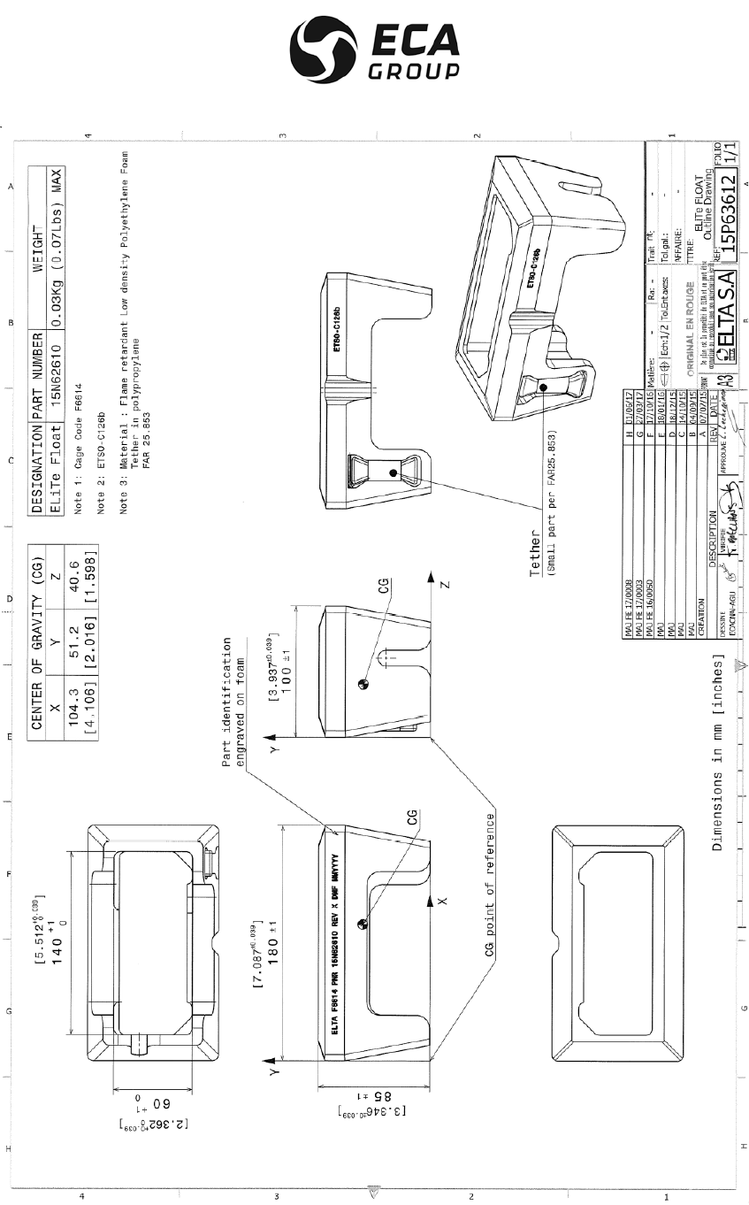
DOCUMENTATION P/N: 15E64259 REV A APPENDIX B page 11
Oct. 10/17
ELiTe Float OUTLINE DRAWING

DOCUMENTATION P/N: 15E64259 REV A APPENDIX B page 12
Oct. 10/17
PAGE INTENTIONALLY LEFT BLANK
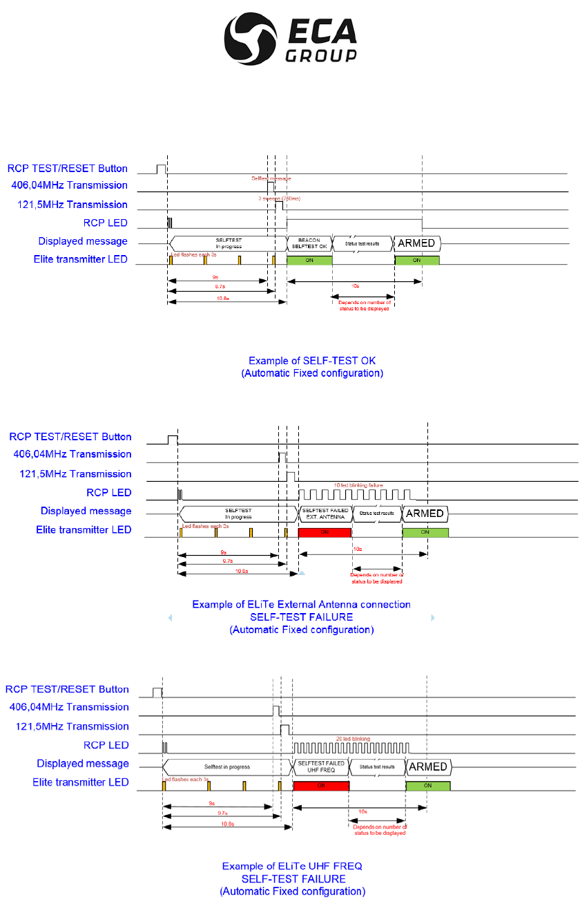
DOCUMENTATION P/N: 15E64259 REV A APPENDIX C page 1
Oct. 10/17
APPENDIX C
TIMING DIAGRAM EXAMPLES
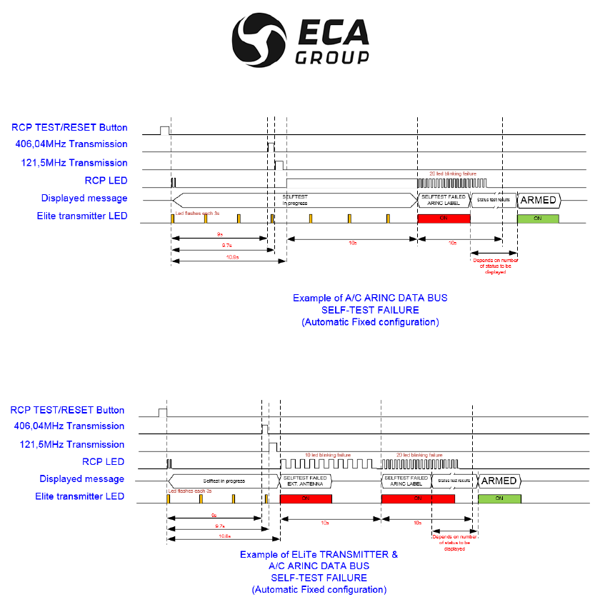
DOCUMENTATION P/N: 15E64259 REV A APPENDIX C page 2
Oct. 10/17
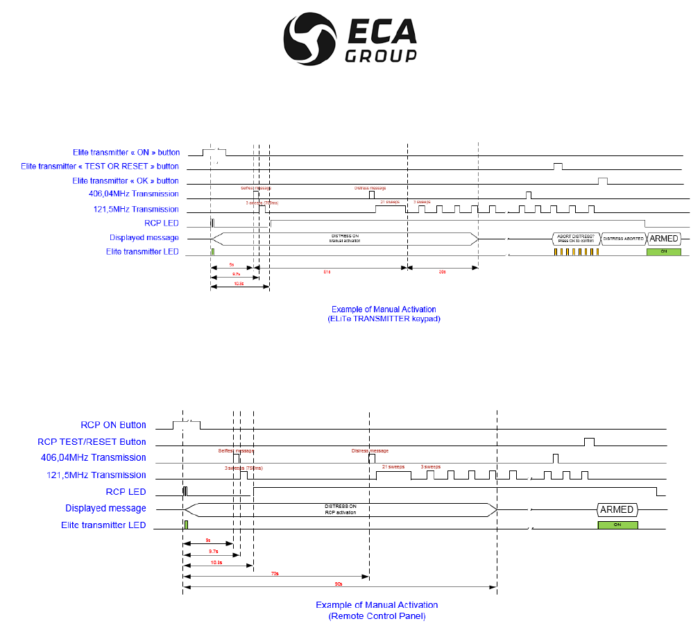
DOCUMENTATION P/N: 15E64259 REV A APPENDIX C page 3
Oct. 10/17

DOCUMENTATION P/N: 15E64259 REV A APPENDIX C page 4
Oct. 10/17
PAGE INTENTIONALLY LEFT BLANK
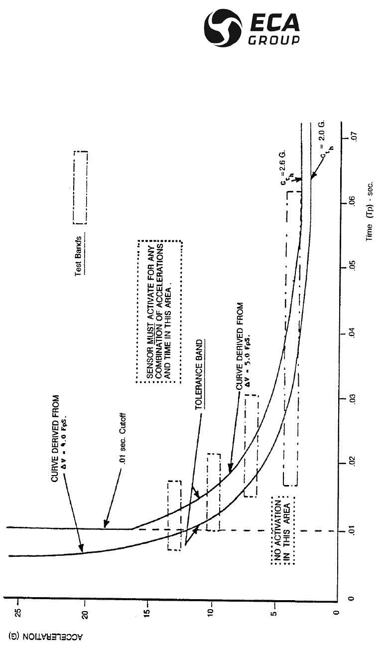
DOCUMENTATION P/N: 15E64259 REV A APPENDIX D page 1
Oct. 10/17
APPENDIX D
CRASH SENSOR RESPONSE CURVE
G-SWITCH SETTING

DOCUMENTATION P/N: 15E64259 REV A APPENDIX D page 2
Oct. 10/17
PAGE INTENTIONALLY LEFT BLANK