EMCEE Broadcast TTU100FA UHF LPTV User Manual TUA100F Mnl Cover Pg 1
EMCEE Broadcast Products UHF LPTV TUA100F Mnl Cover Pg 1
TUA100FA

P.O. Box 68, White Haven, PA 18661 Phone: (570) 443-9575 FAX: (570) 443-9257
MDS MMDS ITFS LPTV
North America South America Europe Asia Australia Africa
Since 1960
TUA100FA
100W SOLID STATE
UHF POWER AMPLIFIER

TUA100FA
100W SOLID STATE
UHF POWER AMPLIFIER
BROADCAST PRODUCTS
04/99

TABLE OF CONTENTS
I. THE TUA100FA POWER AMPLIFIER
1.1 Introduction
1.2 Specifications
1.3 Installation
1.4 Operation
1.5 Warranty and Parts Ordering
II. CIRCUIT DESCRIPTION
2.1 Power Amplifier Drawer
III. MAINTENANCE
3.1 Periodic Maintenance Schedule
3.2 Recommended Test Equipment
3.3 Troubleshooting Chart
3.4 Alignment
3.5 TTU100FA Transmitter Power Calibration
3.6 TU100FA Translator Power Calibration
3.7 Spare Modules and Components
IV. DATA PAK
V. SCHEMATIC DIAGRAMS

i
SECTION I
THE TUA100FA POWER AMPLIFIER
1.1 Introduction ............................................................. 1
61
1.2 Specifications ........................................................... 1
61
1.3 Installation .............................................................. 1
62
1.4 Operation ............................................................... 1
63
1.4a TTU100FA Transmitter ............................................... 1
63
1.4b TU100FA Translator ................................................. 1
64
1.5 Warranty and Parts Ordering ............................................ 1
65

161
SECTION I
THE TUA100FA POWER AMPLIFIER
1.1 Introduction:
The EMCEE model TUA100FA Power Amplifier is rated to provide 100 watts peak visual and
10 watts average aural power on any FCC specified UHF channel extending from 470 to 806MHz
when driven by the EMCEE TTU20F Transmitter or TU20F Translator. This compact, single drawer
unit is completely solid-state and requires only minimal RF alignment, making it easy to service and
maintain.
The TUA100FA was designed for the express purpose of broadcasting as authorized by the Federal
Communications Commission under Part 74, Subpart G of the FCC Rules and Regulations.
1.2 Specifications:
Output Power 100W peak visual
10W average aural
Output Frequency Range 470-806MHz (FCC Ch. 14-69)
Gain 12dB
Channel Flatness ±0.5dB
Input Impedance 50 ohms (N connector)
Output Impedance 50 ohms (N connector)
Spurious Products >50dB below peak sync
Harmonics >60dB below peak sync
Intermodulation Products (IM3) >52dB below peak sync
Differential Gain 5% maximum
Differential Phase 3E maximum
Color Transmission Compatible with PAL, SECAM, and NTSC
Power Requirements 115Vac ± 15%, 60Hz, 700W
230Vac ± 15%, 50Hz (OPTIONAL)
Ambient Temperature !30EC to +50EC

162
Mechanical Dimensions
Power Amplifier Drawer 5.25"H x 19"W x 27"D
Weight 30 lb.
1.3 Installation:
1. After unpacking the EMCEE Model TUA100FA Amplifier, a thorough inspection should be
conducted to reveal any damage which may have occurred during shipment. If damage is
found, immediately notify the shipping agency and advise EMCEE Broadcast Products or its
field representative.
2. Place the TUA100FA in a clean, weatherproof environment with adequate ventilation. Insure
that the amplifier’s ambient temperature does not exceed the !30EC and +50EC limits and
check to see that nothing blocks the exhaust fan located on the rear of the unit.
IMPORTANT
Do not apply ac power to the amplifier at this time since its RF output must be
properly loaded before being placed in operation.
3. Place the amplifier in its permanent location near a 120Vac, 50 or 60Hz, single-phase
receptacle. Unless the customer has specifically requested 220Vac operation, the amplifier
will operate only from a 120Vac source. The ac source should have a minimum power
capacity of 700 watts.
4. Set all circuit breakers and switches, including the ac mains breaker, to the OFF position.
Place an appropriate ac power line protector (surge suppressor) across the ac line that
supplies the amplifier.
5. Connect the EMCEE supplied interconnect harness to the TTU20F Transmitter or TU20F
Translator CONTROL jack (J4) and the TUA100FA Amplifier CONTROL jack (J3). In the
case of a transmitter system, find the two video sense wires connected to the TTU/TU20F
CONTROL jack (J4) end of the harness but broken out separately. If video sense output is
provided by the modulator, connect the striped white/orange/black wire to the video sense
terminal and the black wire to the GND terminal on the modulator’s rear panel. Otherwise,
clip off any bare conductor at the end of each wire and tie them back separately. For a
translator system, plug the 9-pin D connector into the Receiver CONTROL jack (J7).
6. Connect the EMCEE supplied RF cable (N connector to N connector) to the RF OUT jack
(J2) on the rear panel of the TTU/TU20F and the INPUT jack (J1) on the TUA100FA Power
Amplifier's rear panel.
7. Connect the transmitting antenna cable to the Power Amplifier's RF OUT connector (J2).

163
1.4 Operation:
1.4a TTU100FA Transmitter:
Assuming the installation instructions of Section 1.3 have been completed and the transmitter is
receiving baseband video and audio signals, proceed with the following steps to place the
transmitter in operation. It is assumed that the TTU20F is being used as a driver.
1. Place the modulator (A1) power switch to ON and verify that it provides 87.5% video
modulation. If necessary, adjust the modulator for 87.5% video modulation as described in
its instruction manual.
2. On the TTU20F Driver (A2), turn the POWER ADJUST control fully counterclockwise, place
the OPERATE/STANDBY switch to STANDBY, and place the OPERATE/ALIGN switch to
OPERATE. Place the meter switch to FWD and the POWER circuit breaker to ON. Then
verify the following responses of the driver.
a. The fans of the driver should be operating and exhausting air out the rear of the drawer.
b. The driver OPERATE, SYNTH LOCK and DRIVER AMP indicators should be
illuminated green.
c. The TEMP EXCITER, ON, FINAL BIAS, and VSWR OVLD indicators should be
extinguished.
3. Place the TUA100FA Amplifier (A3) POWER switch to ON and meter switch to FWD. Verify
the following responses of the amplifier drawer.
a. The fans of the amplifier should be exhausting out the rear of the drawer.
b. The FINAL ON and AMPL 1 indicators should be illuminated green and the TEMP
indicator should be extinguished.
4. Place the driver OPERATE/STANDBY switch to OPERATE. Then verify the following
responses of the driver.
a. The OPERATE, SYNTH LOCK, and DRIVER AMP indicators should remain
illuminated.
b. The ON and FINAL BIAS indicators should be illuminated green while the VSWR OVLD
and TEMP indicators remain extinguished.
5. Turn the POWER ADJUST control clockwise until a 100% indication appears on the
TUA100FA % POWER meter. The % POWER meter on the TTU20F may indicate less than
100% since a full 20W is not needed to drive the 100W amplifier.
6. Place both meter switches to REFLD and verify that neither % POWER meter indicates more
than 10% returned power. If either reflected power is more than 10%, shut down the
transmitter. Check the VSWR of the transmitting antenna and its associated cable or check
the cable connecting the TTU20F Transmitter to the amplifier drawer.
7. Place the meter switches to FWD for constant monitoring of the transmitter’s output power.
164
The transmitter is now in operation. Check its coverage area for clean, sharp television reception.
If the reception or picture quality is unsatisfactory, examine the amount of power delivered to the
transmitting antenna and, if necessary, examine the antenna orientation, antenna VSWR, and
transmission line VSWR to insure maximum radiation in the proper direction.
1.4b TU100FA Translator:
Assuming the installation instructions of Section 1.3 have been completed and the translator is
receiving RF signals, proceed with the following steps to place the translator in operation. It is
assumed that the TU20F is being used to drive the TUA100FA Power Amplifier.
1. Place the Receiver’s power switch to ON and its OPERATE/ALIGN switch to OPERATE.
Verify the following responses.
a. The CARRIER PRESENT indicator should be illuminated green, indicating that a
VHF/UHF signal of correct frequency and sufficient amplitude is being received.
2. On the TTU20F Driver (A2), turn the POWER ADJUST control fully counterclockwise, place
the OPERATE/STANDBY switch to STANDBY, and place the OPERATE/ALIGN switch to
OPERATE. Place the meter switch to FWD and the POWER circuit breaker to ON. Then
verify the following responses of the transmitter.
a. The fans of the driver should be operating and exhausting air out the rear of the drawer.
b. The driver OPERATE, SYNTH LOCK and DRIVER AMP indicators should be
illuminated green.
c. The TEMP EXCITER, ON, FINAL BIAS, and VSWR OVLD indicators should be
extinguished.
3. Place the TUA100FA Power Amplifier (A3) power switch to ON and meter switch to FWD.
Verify the following responses of the amplifier drawer.
a. The fans of the amplifier should be exhausting out the rear of the drawer.
b. The FINAL ON and AMPL 1 indicators should be illuminated green and the TEMP
indicator should be extinguished.
4. Place the driver OPERATE/STANDBY switch to OPERATE. Then verify the following
responses of the driver.
a. The OPERATE, SYNTH LOCK, and DRIVER AMP indicators should remain
illuminated.
b. The ON and FINAL BIAS indicators should be illuminated green while the VSWR OVLD
and TEMP indicators remain extinguished.
5. Turn the POWER ADJUST control clockwise until a 100% indication appears on the
TUA100FA % POWER meter. The % POWER meter on the TTU20F may indicate less than
100% which is appropriate.

165
6. Place both meter switches to REFLD and verify that neither % POWER meter indicates more
than 10% returned power. If either reflected power is more than 10%, shut down the
transmitter. Check the VSWR of the transmitting antenna and its associated cable or the
cable connecting the TU20F Translator to the TUA100FA Amplifier drawer..
7. Place the meter switches to FWD for constant monitoring of the transmitter’s output power.
The translator is now in operation. Check its coverage area for clean, sharp television reception.
If the reception or picture quality is unsatisfactory, examine the amount of power delivered to the
transmitting antenna and, if necessary, examine the antenna orientation, antenna VSWR, and
transmission line VSWR to insure maximum radiation in the proper direction.
1.5 Warranty and Parts Ordering:
Warranty – EMCEE warrants its equipment to be free from defects in material and workmanship for
a period of one year after delivery to the customer. Equipment or components returned as defective
(prepaid) will be, at our option, repaired or replaced at no charge as long as the equipment or
component part in question has not been improperly used or damaged by external causes (e.g.,
water or lightning). Semiconductors are excepted from this warranty and shall be warranted for a
period of not more than ninety (90) days from date of shipment. Equipment or component parts sold
or used by EMCEE, but manufactured by others, shall carry the same warranty as extended to
EMCEE by the original manufacturer.
Equipment Returns – If the customer desires to return a unit, drawer, or module to EMCEE for
repair, follow the procedure described below:
1. Contact EMCEE Customer Service Department by phone or FAX for a Return Authorization
Number.
2. Provide Customer Service with the following information:
Equipment model and serial numbers.
Date of purchase.
Unit input and output frequencies.
Part number (PN) and Schematic Diagram designator if a module is being sent.
Detailed information concerning the nature of the malfunction.
The customer shall designate the mode of shipping desired (e.g., Air Freight, UPS, FED EX, etc.).
EMCEE will not be responsible for damage to the material while in transit. Therefore, it is of utmost
importance that the customer insure the returned item is properly packed.
Parts Ordering – If the customer desires to purchase parts or modules, utilize the following
procedure:
1. Contact EMCEE Customer Service by phone or FAX indicating the customer's purchase
order number. If the purchase order number is provided by phone, written confirmation of
the order is required.

166
2. Also provide:
The equipment model and serial number.
The unit input and output frequencies.
The quantity, description, vendor, number, and designation of the modules needed as found
in the Spare Modules Lists subsection of this manual.
If a module is required, give the part number (PN) and Schematic Diagram designator
(e.g., 20362238).
Designate the mode of shipping desired (e.g., Air Freight, UPS, FED EX, etc.).
Shipping and billing addresses.
Spare and Replacement Modules and Components – The Spare Modules and Components section
of this manual provides a listing of the modules and some discrete components contained within
the amplifier. This list contains those modules or components considered to be essential bench-
stock items and should be available to the maintenance technician at all times. The Schematic or
Interconnection Diagram is the governing document of this manual. Should there be a discrepancy
between a modules or components list and a diagram, the diagram takes precedence. Such a
discrepancy is possible since manufacturing changes cannot always be incorporated immediately
into the instruction manual.
Module Referencing – The transmitter consists of drawers containing modules and components.
Each drawer is given a reference designator starting with A1. Components and modules located
in a drawer are referred to by their respective designators, preceded by the designator of the drawer
in which they reside. Hence, the designator A1PS2 refers to power supply PS2 in drawer A1. This
standard applies for all modular levels, i.e., A1A6A3 represents module A3, located in module A6,
located in drawer A1. Components mounted directly to the cabinet take only a component reference
designator. In the circuit description, Section 2, the full reference designator is given only with the
schematic or interconnection diagram. In the text, the modules are referred to by their module
number only, unless a module is mentioned that is located in a different drawer. Module
designators on interconnect diagrams do not take the drawer designators.
For EMERGENCY technical assistance, EMCEE offers a toll free, 24-hour,
7-day-a-week customer service hot line: 1-800-233-6193.

ii
SECTION II
CIRCUIT DESCRIPTION
2.1 Power Amplifier Drawer ................................................... 2
61
2.1a 100W UHF Amplifier Module ............................................ 2
61
2.1b UHF Notch Filter ..................................................... 2
62
2.1c Metering Coupler ..................................................... 2
62
2.1d Metering Detector .................................................... 2
62
2.1e Metering Display Assy ................................................. 2
63
2.1f Indicator Circuit ...................................................... 2
64
2.1g 32V Power Supply .................................................... 2
64

261
SECTION II
CIRCUIT DESCRIPTIONS
2.1 Power Amplifier Drawer:
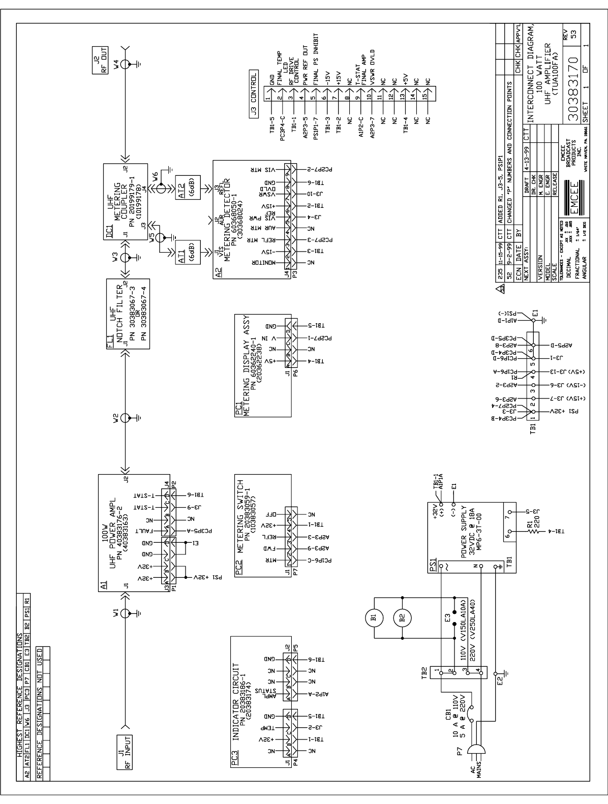
Interconnection Diagram 30383170/Rev 53 ò A3
RF OUT (J2) 100W (+50dBm) peak visual
10W (+40dBm) average aural
Drawer Gain (J1-J2) 12dB Minimum
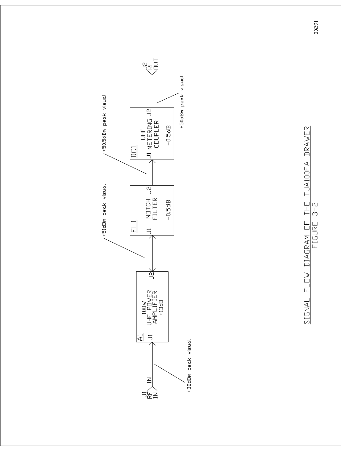
The Power Amplifier drawer (A3) amplifies the composite RF output signal from the TTU20F
Transmitter or the TU20F Translator (A2) to obtain 100 watts peak visual output with 10 watts of
average aural. The drawer consists of an RF amplifier chain, a power detection/metering circuitry
and an indicator circuit. Some monitoring and control of this drawer is also performed by the
TTU/TU20F Driver. The RF amplifier chain is made up of a single LDMOS 100W UHF Amplifier
module (A1), a 4.5MHz UHF Notch Filter (FL1) and a UHF Metering Coupler (DC1). The power
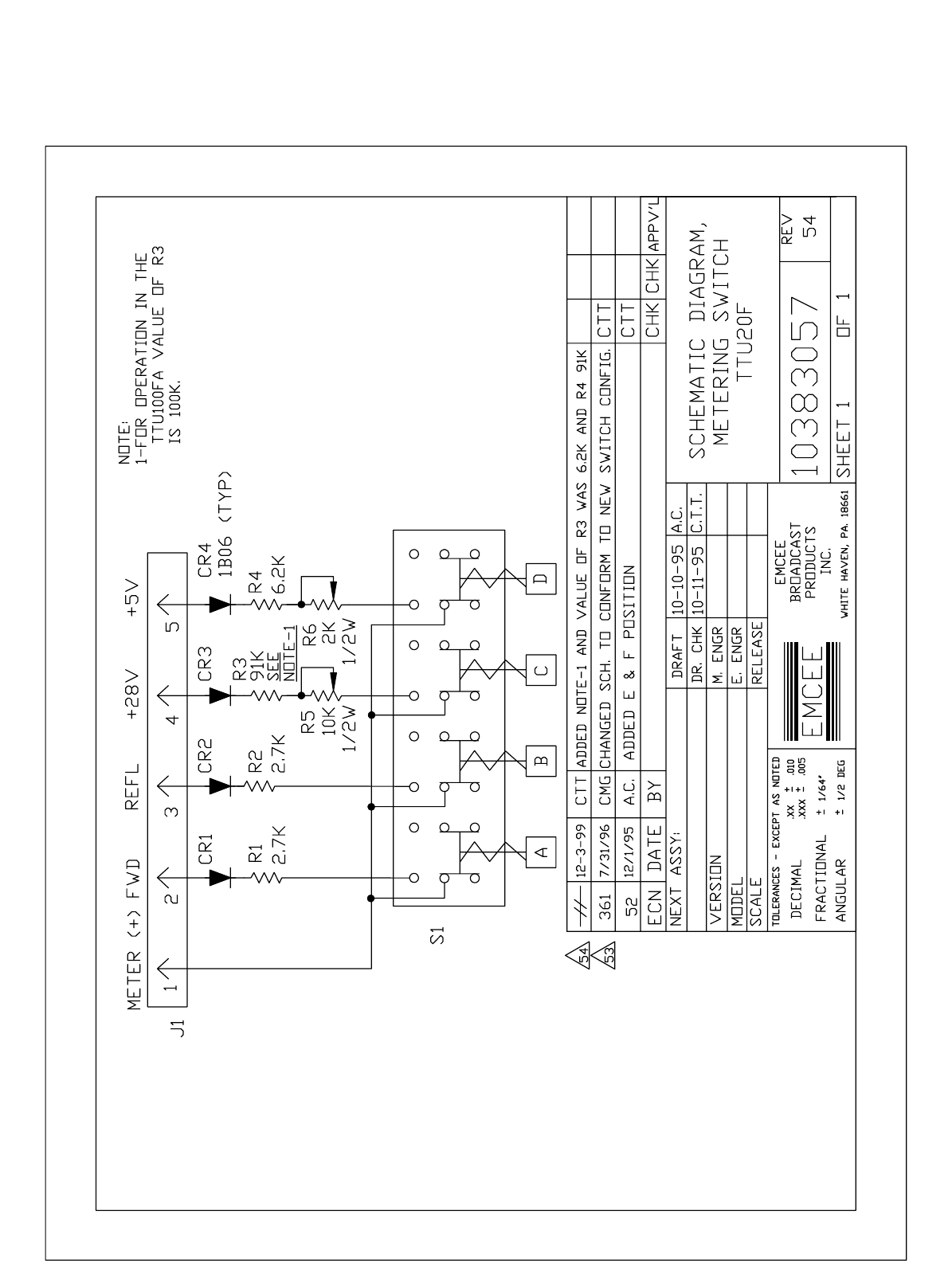
detection/metering circuitry includes a Metering Detector (A2), Metering Switch (PC2), Metering
Display Assembly (PC1) and an Indicator Circuit (PC3). The amplifier drawer has an internal 32V
Power Supply (PS1) and slaves ±15V and +5V from the ±15V/+5V Power Supply (A2PS2) in the
TTU/TU20F Upconverter/Amplifier Drawer.
The drawer’s front panel provides a display of the amplifier’s % POWER using the Metering
Display Assembly (PC1), which is a 30-segment LED bar array driven by information via the
Metering Switch (PC2). Also on the front panel is the Indicator Circuit (PC3) which has three LEDs
to indicate if the drawer is operational, the power amplifier has overheated, or if the amplifier
module (A1) has experienced a fault.
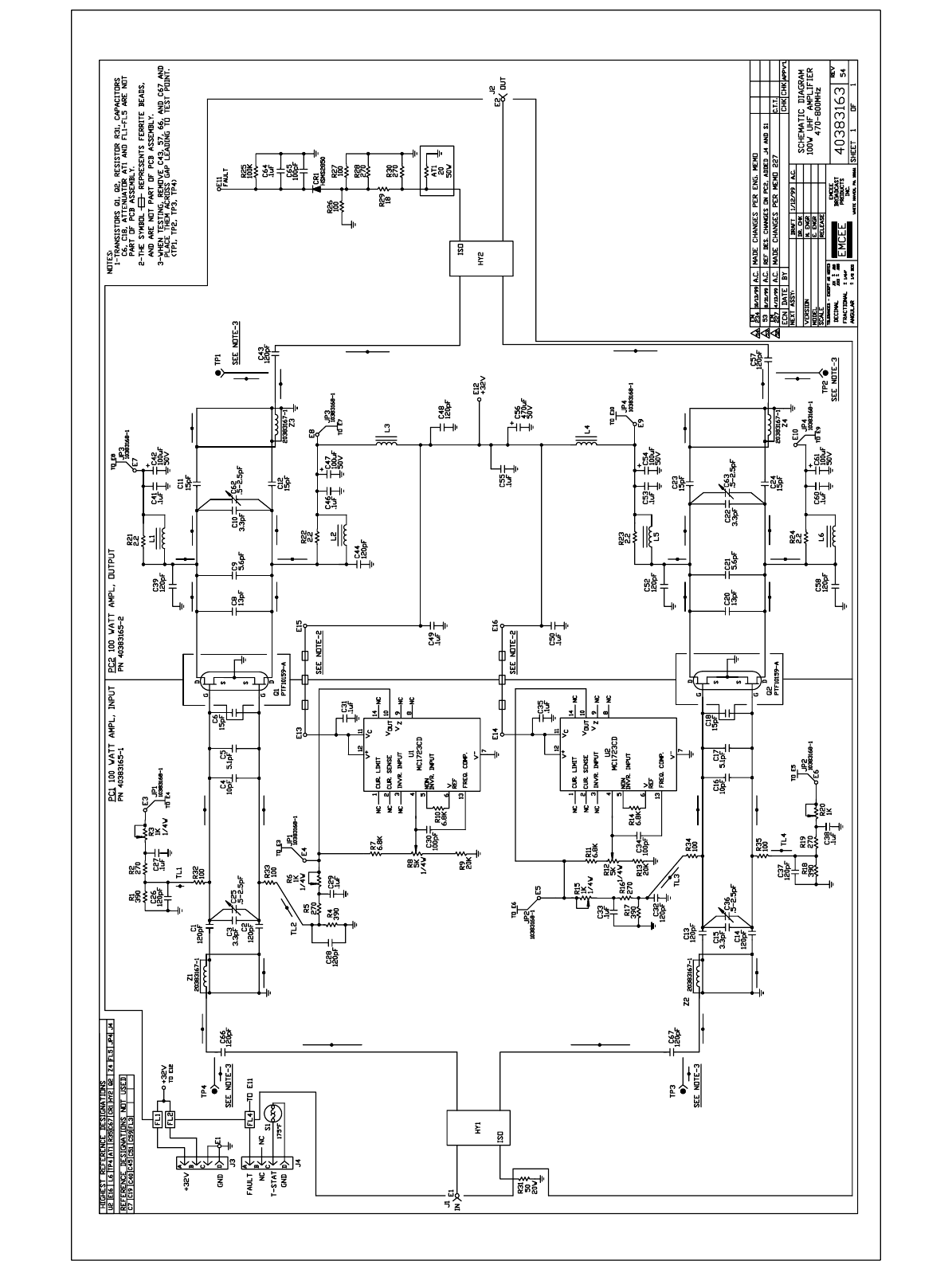
2.1a 100W UHF Amplifier:
Schematic Diagram 40383163/Rev 54 ò A3A1
Gain 13dB
The TUA100FA contains a single 100 watt UHF power amplifier module (A1) having a nominal
gain of 13dB in the UHF frequency band of 470 to 806MHz. The gain is derived from two parallel,
class AB push-pull, LDMOS transistors (Q1, Q2) operating at 32Vdc.
The RF signal enters the module through connector J1 and is split by a 90E hybrid, HY1. Each
signal is then brought to separate coaxial baluns (Z1/Z2) both providing two signals that are 180E
out of phase at the gates of their respective transistor pairs. The gate-source bias voltages for Q1
and Q2 are generated by monolithic voltage regulators U1 and U2 which are fed directly by 32V
at pins 11 and 12. Potentiometers R8 and R12, in conjunction with resistors R7, R9, R11 and R13,
control the outputs of U1and U2 and are typically set for a 10V at pin 10 of each regulator.
Potentiometers R6 and R15 along with R4, R5, R16 and R17 provide individual fine adjustment
for the gate-source biases of Q1 and Q2, a potential of approximately 4V. Input matching and
signal coupling for each transistor are provided by capacitors C1-C6 with C25 for Q1, and C13-C18
262
with C36 for Q2. The outputs of each transistor pair are transformed into combined signals by
coaxial baluns Z3 and Z4. These two signals are then combined again by 90E hybrid HY2 and
delivered to the module output at J2. Output matching and coupling for each transistor pair are
furnished by capacitors C8-C12, C62 for Q1, and C20-C24, C63 for Q2. Inductors L1 through L6
are employed as RF chokes with the remaining capacitors used for RF bypass.
If a fault occurs in either transistor pair, the difference in power at the hybrid HY2 inputs will create
an imbalance causing excessive power to appear at the HY2 ISOlation port. To monitor this fault,
a power detection circuit, centered around diode CR1, transforms this excess power into a DC
voltage which appears as a TTL high at terminal E11. On the Indicator Circuit (PC3) board this
logic level high will change the front panel AMPL 1 status LED from green to red.
2.1b UHF Notch Filter:
Schematic Diagram N/A ò A3FL1
Insertion Loss 0.5dB maximum
Notch Depth !12dB minimum
Notch Frequency Visual Carrier !4.5MHz
Aural Carrier +4.5MHz
This filter is a tunable two-section notch filter that removes the spurious products created through
common amplification 4.5MHz below the visual carrier and above the aural carrier of the
transmitted channel. Each notch has a minimum attenuation of 12dB, with the insertion loss of the
passband at 0.5dB maximum.
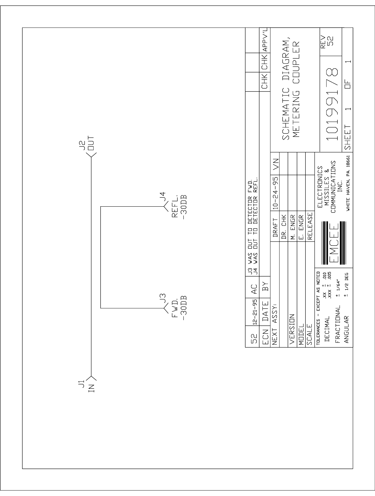
2.1c Metering Coupler:
Schematic Diagram 10199178/Rev 52 ò A3DC1
Insertion Loss (J1-J2) <0.5dB
FWD Coupling (J1-J3) 30dB
REFL Coupling (J1-J4) 30dB
The Metering Coupler is a four port device designed to provide forward and reflected RF samples
to the Metering Detector (A2) with minimal loss to the output signal. The RF signal from the Notch
Filter is applied to the coupler’s input port (J1) and exits the coupler at J2 with a maximum of 0.5dB
of loss. A !30dB sample of the signal’s forward power is provided at J3, and a !30dB sample of
the reflected power is provided at J4. These two signals are connected through 6dB attenuators
(AT3, AT4) to the metering detector which then provides DC signals, proportional to the amplifier’s
output power, to the Control Board, AGC circuit, and Metering Switch.
263
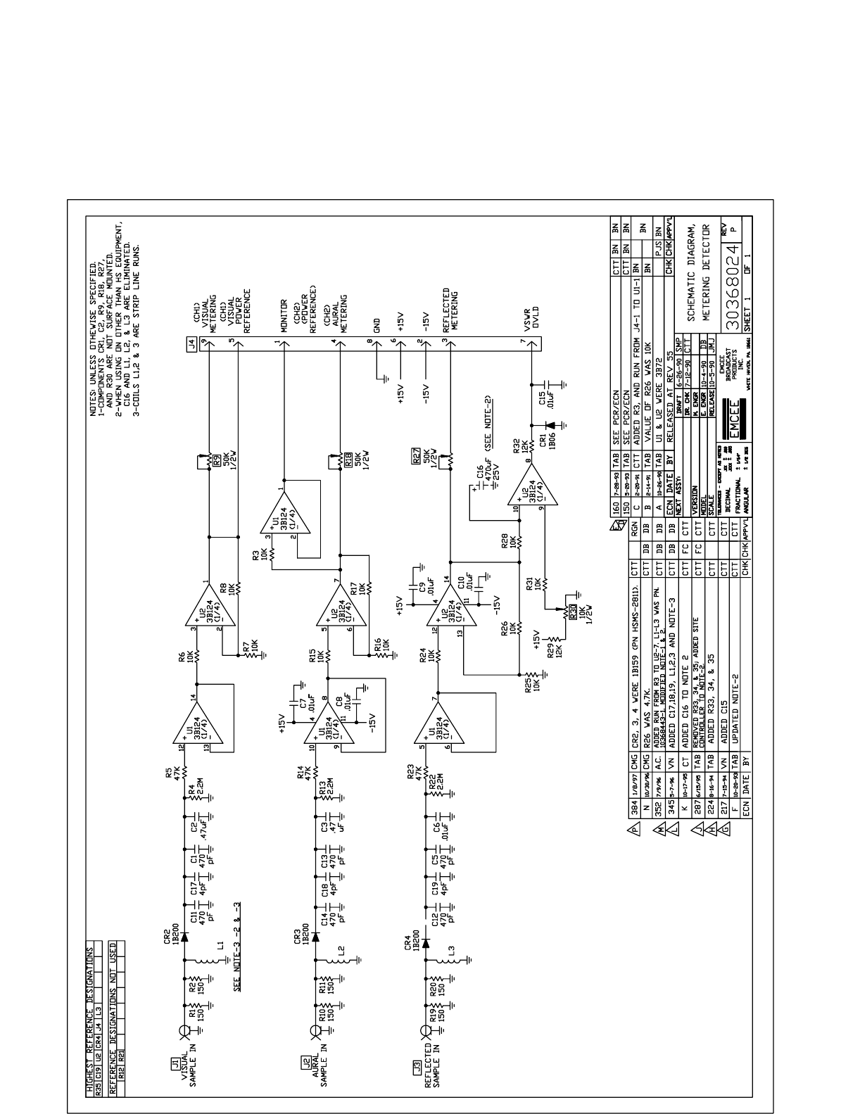
2.1d Metering Detector:
Schematic Diagram 30368024/Rev P ò A3A2
The Metering Detector contains three circuits for monitoring signal levels. Each of these circuits
can take an RF signal at its input and provide a DC voltage at its output proportional to the input
signal’s strength. Only two of the detector circuits are used in this application. From the Metering
Coupler (DC1) a sample of the amplifier’s forward signal is supplied to the VISual port of the
detector, and a sample of the reflected power is provided to the detector’s REFLected input. The
front end or detector portion of each circuit is basically the same. Diodes CR2 and CR4, together
with their surrounding components, convert the sampled on-channel RF signals to positive dc
voltages proportional to the detected RF power. Detection of the sampled forward output is
accomplished by CR2 in conjunction with R4 and C2 which form a time constant of 1 second. R4
is the dc load while C1 and C11 form the RF ground of the visual power detector. Detection of the
sampled reflected signal is the same except for a faster time constant, as R22/C6 form a time
constant of 1 millisecond. The positive dc voltages from the visual and reflected power detectors
are processed by buffer amplifiers U1 and U2 which provide voltage gains of 1V/V and 2V/V,
respectively. These buffer amplifiers also provide isolation between the % POWER meter and the
detectors. The settings of potentiometers R9 and R27 determine the voltage level applied to the
% POWER meter when the meter switch (A3PC2) is in its FWD or REFL position. Since common
amplification of the visual and aural carriers is provided in this amplifier, the AURal detector circuit
is not used.
A dc voltage proportional to the amplifier's output power is applied to pin 5 of connector J4,
designated VIS PWR REF. This power reference is fed back to the driver's (A2A1) AGC circuit
contained in the IF/Upconverter. This voltage ultimately controls the attenuation of the composite
IF carrier so that the amplifier's output is automatically maintained at its rated value.
A dc voltage proportional to the amplifier's reflected output power is fed to pin 10 of comparator
U2. This voltage is compared to a reference voltage at pin 9 whose magnitude is determined by
potentiometer R30. With R30 properly set (see paragraph 3.5b), the voltage on pin 10 will be
greater than the reference voltage whenever the amplifier's reflected power is more than 10% of
its rated forward power. As a result, the output of the comparator saturates in the positive mode
applying approximately +4Vdc to the VSWR OVLD line. This voltage instructs the Control Board
(A2PC1) in the transmitter/driver that a VSWR overload condition has been detected. When the
amplifier's reflected power is less than 10% of its rated forward power, the voltage on pin 10 of
comparator U2 will be less than the reference voltage. As a result, the comparator saturates in the
negative mode, diode CR1 is forward biased, and approximately !0.7Vdc is applied to pin 7 of
connector J4. This voltage instructs the Control Board that no VSWR overload condition exists.
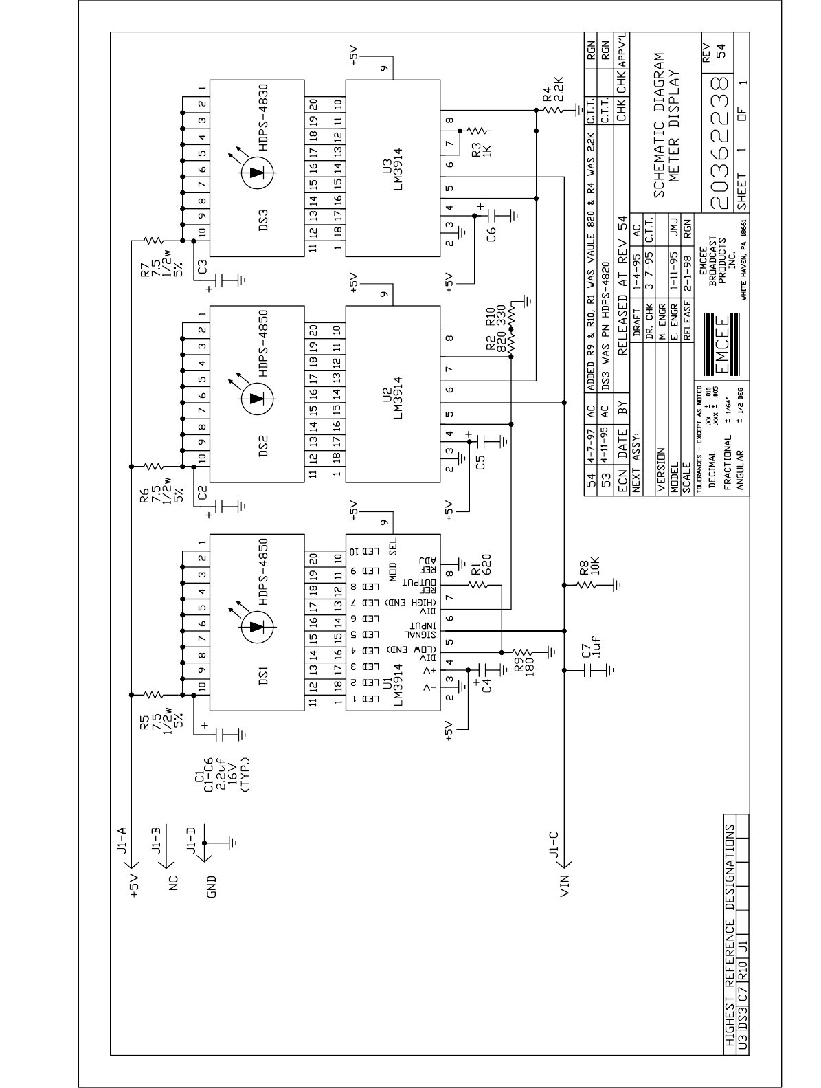
2.1e Metering Display Assy:
Schematic Diagram 20362238/Rev 54 ò PC1
The Metering Display (PC1) consists of three 10-segment LED bar graphs (DS1, DS2, and DS3)
and their drivers (U1, U2 and U3). Light Emitting Diodes DS1 and DS2 are green with DS3 colored
red. The drivers are scaled so that at 100% forward output power all segments of DS1 and DS2
should be illuminated and at 50% only segments of DS1 should be illuminated. When the amplifier
is operating at more than 100%, all segments of DS1 and DS2 will be lit with some or all portions
of DS3 illuminated depending on the amount of output power over 100%.

264
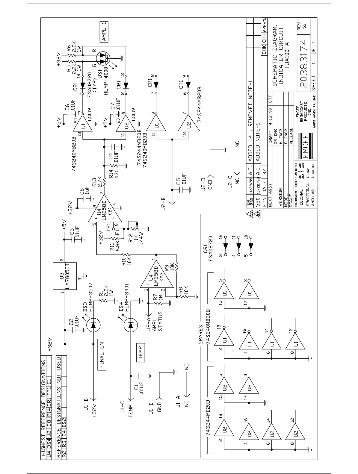
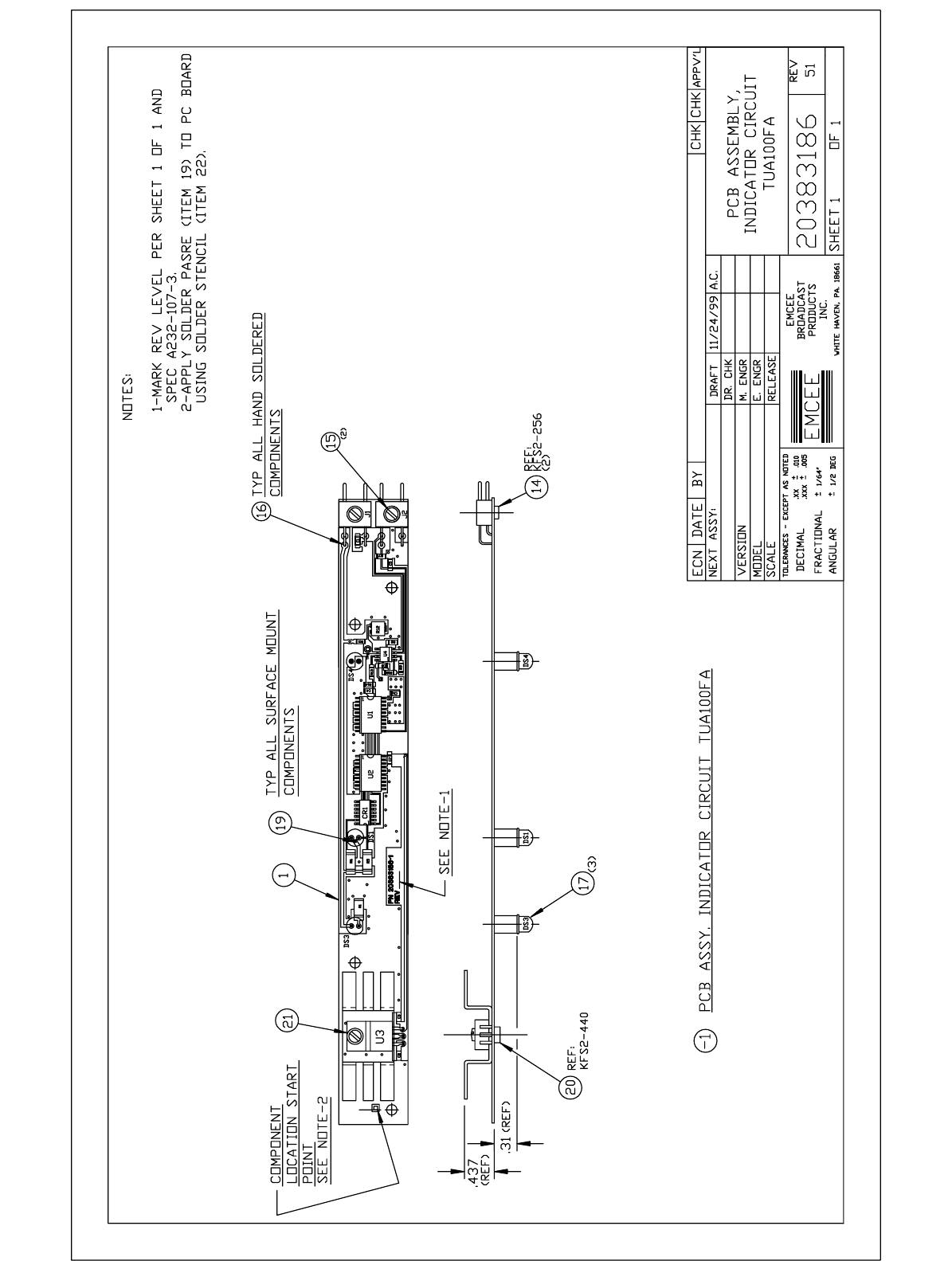
2.1f Indicator Circuit:
Schematic Diagram 20383174/Rev 53 ò A3PC3
The Indicator Circuit (PC3) is mounted to the front panel and contains three indicator LEDs. The
FINAL ON indicator illuminates when the power switch is turned on and the 32V Power Supply
(PS1) distributes power throughout the drawer. The TEMP LED illuminates when the thermostat,
mounted on the heat sink of the power amplifier module, detects excessively high temperatures
(175EF/80EC). When the 100W UHF Power Amplifier (A1) module is functioning properly, a logic
"0/ " is present on J2-A causing inverter U1 in the AMPL 1 status circuit to output a logic "1", placing
approximately 5V across the green section of LED DS1. Buffer U2 essentially passes the logic
"0/ " bypassing the red section of the LED to ground, thus extinguishing it. If the amplifier module
experiences a fault, a logic "1" is put on the AMPL 1 STATUS input J2-A, and the green LED
section extinguishes while the red section illuminates. 32V is converted to +5V on this board by
regulator U3 for use by inverters and buffers U1 and U2.
2.1g 32V Power Supply:
Schematic Diagram N/A ò A3PS1
Output 32V @ 18.7A Max
A +32V, 600 watt high performance, high efficiency power supply is used to power the 100W UHF
Power Amplifier module. The supply is a single output, power factor corrected switching type.
The 32V Power Supply is not field repairable. If defective, it should be returned to EMCEE for
repair or replacement.

iii
SECTION III
MAINTENANCE
3.1 Periodic Maintenance Chart ............................................. 3
61
3.2 Recommended Test Equipment .......................................... 3
61
3.3 Troubleshooting Chart ................................................... 3
62
3.4 Alignment ............................................................... 3
64
3.4a UHF Notch Filter .................................................... 3
64
3.5 TTU100FA Transmitter Power Calibration ................................ 3
64
3.5a Forward Power ...................................................... 3
64
3.5b Reflected Power .................................................... 3
65
3.6 TU100FA Translator Power Calibration ................................... 3
66
3.6a Forward Power ...................................................... 3
66
3.6b Reflected Power .................................................... 3
67
3.7 Spare Modules and Components ........................................ S
61

361
SECTION III
MAINTENANCE
3.1 Periodic Maintenance Schedule:
OPERATION RECOMMENDATION
ALIGNMENT Upon installation and at one-year intervals
thereafter (see subsection 3.4).
OUTPUT POWER CALIBRATION Same as above (see subsection 3.5).
FANS Inspect as often as possible (at least monthly)
and clean when necessary. No lubrication
needed.
3.2 Recommended Test Equipment:
EQUIPMENT MANUFACTURER MODEL #
Digital Multimeter HEWLETT PACKARD E2378A
Oscilloscope TEKTRONIX 2232
VHF Sweep Generator WAVETEK 2001
50 Ohm RF Detector TELONIC BERKELEY 8553
30dB 150W Attenuator NARDA 769-30
Power Meter HEWLETT PACKARD 435B
Step Attenuator KAY 1/432
Frequency Counter HEWLETT PACKARD 5386A
Spectrum Analyzer HEWLETT PACKARD 8594E
NTSC Video Generator TEKTRONIX TSG100
Television Modulator EMCEE EM1
Mixer MINI-CIRCUITS ZP-2

362
3.3 Troubleshooting Chart:
The following chart is an aid to determining and correcting the causes of faults that may occur in this
amplifier. Under normal operating conditions, the FINAL ON indicator should be illuminated green
with the TEMP and AMPL 1 indicators unlit. If a problem develops, note the type of problem, the
state of the indicator LEDs and % POWER meter and compare them to this chart. Refer to the
Troubleshooting Chart in the TTU20F Transmitter or TU20F Translator manual as necessary.
TROUBLESHOOTING CHART
PROBLEM INDICATORS CAUSE SOLUTION
NO OUTPUT
POWER ALL LEDs UNLIT No 32V or 5V available Check plug connections
P9/P10 and 5V regulator
(U3) output on Indicator
Circuit board PC3.
Faulty module or 32V
Power Supply Shut off Xmtr/Xltr RF
drive. While monitoring
the 32V supply, remove
the dc plug from each
module and PC board in
the drawer and the wire
harness to the driver. If
the 32V returns when a
plug is removed, replace
the associated module. If
32V does not return with
all plugs removed,
replace power supply.
TEMP YELLOW
AMPL 1 GREEN
FINAL ON GREEN
% POWER 0
DRIVER STBY
High ambient temperature
inside drawer Ensure fans are opera-
tional and are not
blocked.
Faulty thermostat If amplifier A1 is cool,
measure resistance
across the thermostat.
Replace thermostat if a
short is present.
LOW OUTPUT
POWER OR
DISTORTED
OUTPUT
AMPL 1 RED Faulty amplifier module Replace amplifier module.
NO fault indicated Output power calibration
is incorrect See Section 3.5 or 3.6.

TROUBLESHOOTING CHART
PROBLEM INDICATORS CAUSE SOLUTION
363
LOW OUTPUT
POWER OR
DISTORTED
OUTPUT
NO fault indicated Notch Filter misaligned See Section 3.4a.
Xmtr/Xltr Driver
misaligned Refer to the TTU/TU20F
Instruction Manual.

364
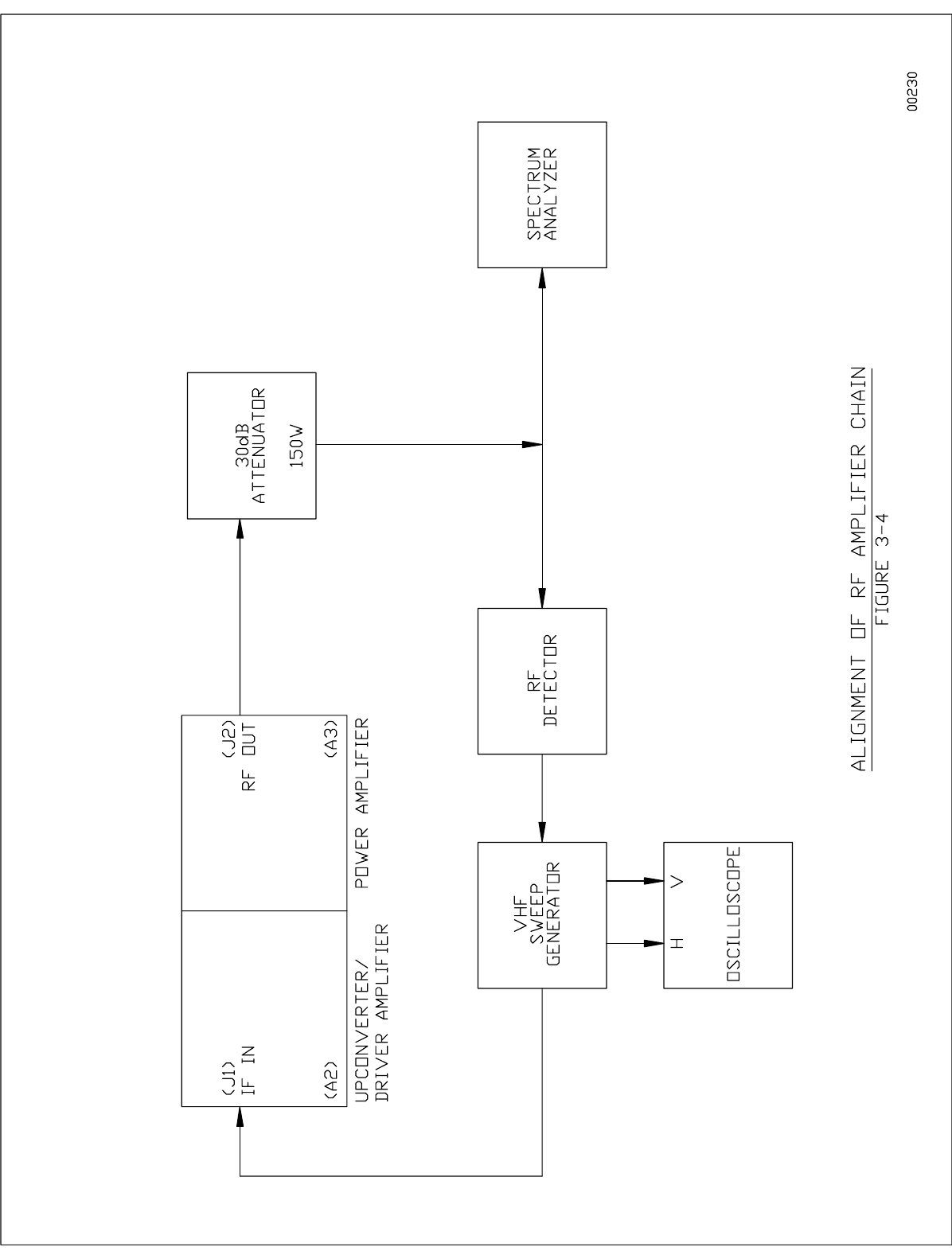
3.4 Alignment:
3.4a UHF Notch Filter:
1. Place the Amplifier Drawer POWER ON switch to off. Disconnect the input cable from the
Notch Filter and connect the filter’s input directly to the sweep generator's RF output.
2. Place the RF Detector directly on the RF OUTPUT connector (J2) of the transmitter.
3. Tune the sweep generator to the center frequency of the transmitter's output channel
employing a 20MHz sweep width display on the oscilloscope. Display the 1MHz markers.
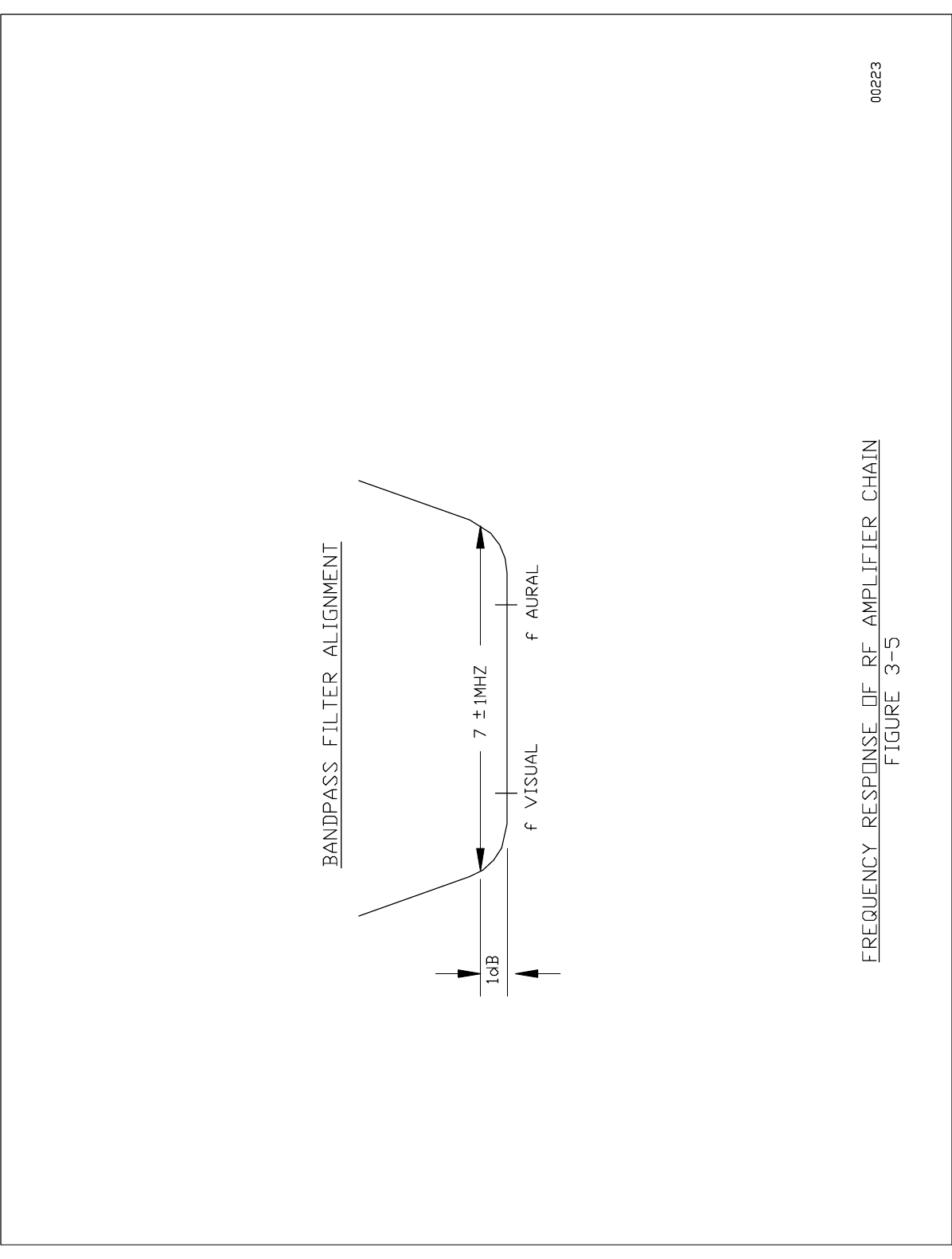
4. The filter adjustments are the two threaded rods located on the short side of the filter
accessible through the left side panel toward the rear of the drawer. If they are not marked,
slowly adjust one and observe which notch moves on the scope and set accordingly. Do not
switch the positions of the individual notches.
Set the lower notch to (Visual Carrier Frequency ! 4.5MHz).
Set the upper notch to (Aural Carrier Frequency + 4.5MHz).
The visual carrier frequency for the appropriate UHF channel can be found in
Section 4, the Data Pak, or in Table 261.
5. Remove the sweeper cable from the filter input and the RF Detector from the drawer output.
Replace the Notch Filter input cable.
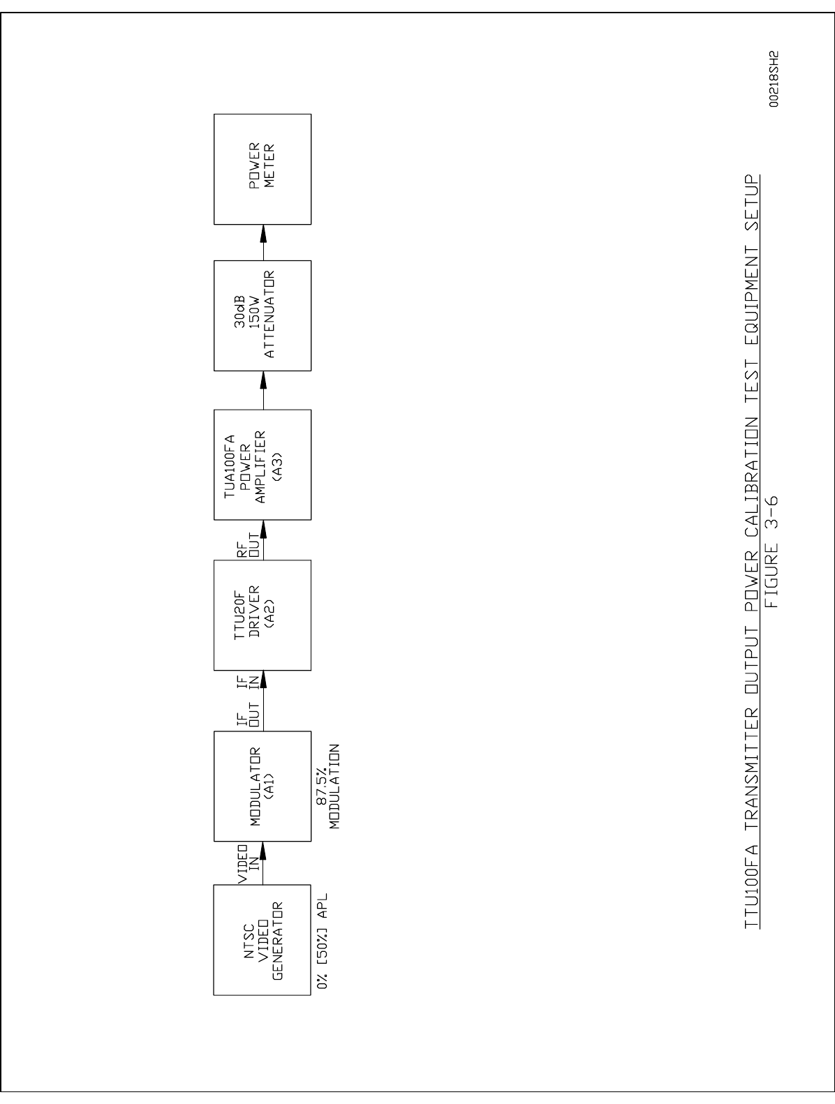
3.5 TTU100FA Transmitter Power Calibration:
To ensure proper transmission, the output power level and % Power Meter calibration should be
checked once every year. With the meter switch in the FWD position, the % Power Meter has been
factory calibrated for 100% with the transmitter providing 100 watts peak visual and 10 watts
average aural. The following calibration procedure assumes that the visual carrier has 87.5% video
modulation and 0% average picture level (APL). In the following steps, the power levels stated are
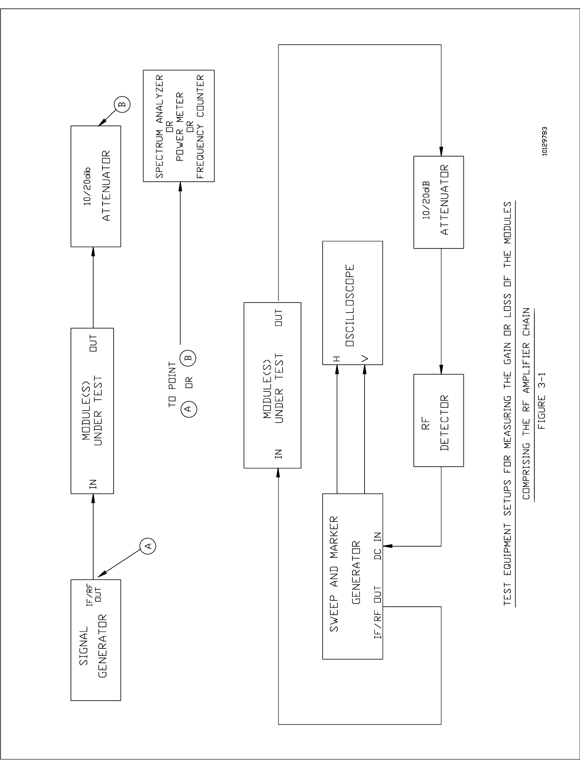
those expected at the output of the transmitter. Therefore, when measuring these power levels as
shown in Figure 366, be sure to take into account the 30dB factor provided by the attenuator. Power
levels at 50% APL (stair steps) are included in brackets following the power levels at 0% APL (SYNC
only).
3.5a Forward Power:
1. With the TTU20F in STANDBY and the TUA100FA Amplifier off (POWER ON circuit breaker
down), set up the test equipment as shown in Figure 366.
365
2. Verify that the modulator is operating and providing 87.5% video modulation. Place the
100 Watt Amplifier POWER switch to ON and make sure the Amplifier’s Meter Switch is in
the FWD position. Place the TTU20F Transmitter STANDBY switch to OPERATE.
3. To set the output power, adjust the TTU20F POWER ADJUST for an external power meter
reading of 69.5W [44W]. Note that 100W peak visual at 0% [50%] APL and 87.5%
modulation plus 10W average aural equals 69.5W [44W] average power.
4. To check or adjust the visual to aural carrier ratio, replace the power meter in Figure 366 with
a spectrum analyzer. Adjust the aural carrier level on the modulator for the desired ratio.
Remove the spectrum analyzer and return the power meter to the Transmitter’s output and
reset the output power for an external power meter reading of 69.5W [44W].
5. With the external power meter showing the correct power, place the meter switch to FWD
and check the TUA100FA front panel % Power Meter for a 100% indication. If this reading
is not obtained, adjust potentiometer R9 of the Metering Detector (A3) for a 100% indication.
The Metering Detector is mounted on the right-hand side wall near the front of the amplifier
drawer and is accessible through the holes in the side wall. The % Power Meter on the
TTU20F Transmitter/Driver will indicate less than 100% which is an appropriate reading.
3.5b Reflected Power (OPTIONAL):
6. On the right side wall of the TUA100FA Power Amplifier drawer, adjust potentiometer R30
of the Metering Detector fully clockwise to disable the VSWR overload detection circuit.
Place the amplifier drawer meter switch to REFL.
7. Place the Transmitter/Driver OPERATE/STANDBY switch to STANDBY and the OPERATE/
ALIGN switch to ALIGN. Remove and reverse the forward power (J3) and reflected power
(J4) coupling port cables on the Metering Coupler (DC1). J1 and J3 of the Metering Detector
(A3) should now be connected to J4 and J3 of the Metering Coupler (DC1), respectively.
This simulates an open circuit at the amplifier's RF OUTput (J2) delivering maximum
returned power to the REFL port of the Metering Detector. Insert a step attenuator between
the modulator's IF OUTPUT and the transmitter's IF INPUT and set the step attenuator for
10dB attenuation.
8. Place the Transmitter/Driver OPERATE/STANDBY switch to OPERATE. Remove the
attenuation from the step attenuator for an external power meter reading of 69.5W [44W].
Check the amplifier drawer's front panel REFL meter for a 100% [70%] reading. If
necessary, adjust potentiometer R27 of the amplifier Metering Detector for the proper
reading. R7 is accessible through the right-hand side wall of the drawer.
9. Decrease the transmitter's power to 50% by increasing the step attenuator 3dB for an
external power meter reading of 34.75W [22W]. This power level is used for setting the trip
point of the VSWR overload detection circuit. Adjust R30 of the amplifier’s Metering Detector
slowly counterclockwise until the front panel VSWR OVLD indicator illuminates red and the
Transmitter/Driver is placed in standby.

366
10. Check the VSWR OVLD trip point by setting the step attenuator for an additional 1dB of
attenuation. Press the momentary VSWR RESET switch to reset the transmitter and
remove the additional 1dB of attenuation from the step attenuator. The VSWR OVLD circuit
should again trip. If it does not, repeat this section beginning at step #6.
11. Place the OPERATE/STANDBY switch to STANDBY. Return the Metering Coupler cables
to their original ports, J3 and J4. Reinstall the top cover, slide the drawer back into the
cabinet and secure it properly. Properly load the transmitter and place the Driver OPERATE/
ALIGN and OPERATE/STANDBY switches to OPERATE.
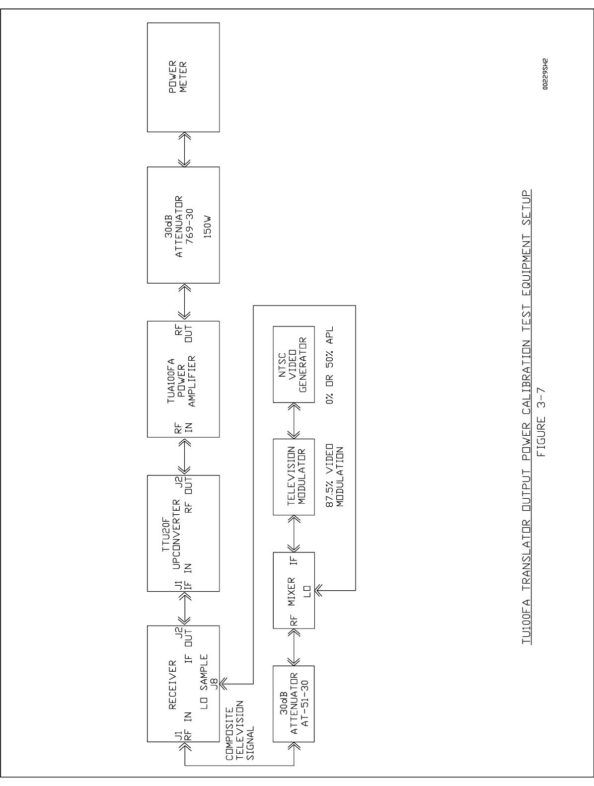
3.6 TU100FA Translator Power Calibration:
To ensure proper transmission, the output power level and % Power Meter calibration of the
translator should be checked once every year. With the meter switch in the FWD position, the
TUA100FA Amplifier % Power Meter has been factory calibrated for 100% with the translator
providing 100 watts peak visual and 10 watts average aural. The following calibration procedure
assumes that the composite signal received by the translator has the aural carrier 10dB down from
the visual with the visual carrier having 87.5% video modulation and 0% average picture level (APL).
In the following steps, the power levels stated are those expected at the output of the translator.
Therefore, when measuring these power levels as shown in Figure 367, be sure to take into account
the 30dB factor provided by the attenuator. Power levels at 50% APL (stair steps) are included in
brackets following the power levels at 0% APL (SYNC only).
This procedure also assumes the setup in Figure 367 is being used and that the output of the
receiver drawer has been correctly calibrated. If the received broadcast channel frequency is in the
VHF band (Ch.2-13), the mixer can be deleted from the test setup and a VHF agile modulator set
on the correct channel may be connected directly to the RF INput (J1) of the Receiver drawer
through an attenuator.
3.6a Forward Power:
1. With the TU20F Translator drawer in STANDBY and the TUA100FA Amplifier POWER ON
circuit breaker switch open (down), set up the test equipment as shown in Figure 367.
2. Verify that the modulator is providing 87.5% video modulation with the aural 10dB below the
visual and that the input signal is at the correct frequency (Receiver’s input channel) and at
an amplitude between !40dBm to !47dBm. Place the TUA100FA 100 Watt Power Amplifier
into operation and make sure the Meter Switch is displaying FWD power. Turn the TU20F
Transmitter/Driver ON and place both the OPERATE/STANDBY and OPERATE/ALIGN
switches to OPERATE.
3. To set the output power, adjust the Driver’s POWER ADJUST control for an external power
meter reading of 69.5W [44W]. Note that 100W peak visual at 0% [50%] APL and 87.5%
modulation plus 10W average aural equals 69.5W [44W].
367
4. With the external power meter reading the correct output power, place the meter switch to
FWD and check the TUA100FA Amplifier front panel % Power Meter for a 100% indication.
If this reading is not obtained, adjust potentiometer R9 of the Metering Detector (A3) for a
100% indication. The Metering Detector is mounted on the right-hand side wall near the front
of the amplifier drawer and is accessible through the holes in the side wall. The % Power
Meter on the TU20F Driver will read less than 100% which is an appropriate indication.
3.6b Reflected Power (OPTIONAL):
5. On the right side wall of the 100W Power Amplifier drawer, adjust potentiometer R30 of the
Metering Detector fully clockwise to disable the VSWR overload detection circuit and place
the meter switch to REFL.
6. Place the Transmitter/Driver OPERATE/STANDBY switch to STANDBY and the OPERATE/
ALIGN switch to ALIGN. In the amplifier drawer remove and reverse the forward power (J3)
and reflected power (J4) coupling port cables on the Metering Coupler (DC1). J1 and J3 of
the Metering Detector (A3) should now be connected to J4 and J3 of the Metering Coupler
(DC1), respectively. This simulates an open circuit at the amplifier’s RF OUTput (J2)
delivering maximum returned power to the REFL port of the Metering Detector. Insert a step
attenuator between the Receiver’s IF OUTPUT and the Transmitter’s IF INPUT and set the
step attenuator for 10dB attenuation.
7. Place the Transmitter’s OPERATE/STANDBY switch to OPERATE. Remove attenuation
from the stepper for an external power meter reading of 69.5W [44W]. Check the amplifier
drawer's front panel meter for a 100% [70%] reading and, if necessary, adjust potentiometer
R27 of the Amplifier’s Metering Detector for the proper reading. R27 is accessible through
the right-hand side wall of the drawer.
8. Decrease the translator's power to 50% by increasing the step attenuator 3dB for an external
power meter reading of 34.75W [22W]. This power level is used for setting the trip point of
the VSWR overload detection circuit. Adjust R30 of the Amplifier’s Metering Detector slowly
counterclockwise until the front panel VSWR OVLD indicator illuminates red and the
Translator/Driver drops into standby.
9. Check the VSWR OVLD trip point by increasing the step attenuator an additional 1dB. Press
the momentary VSWR RESET switch to reactivate the Translator and remove the additional
1dB of attenuation from the attenuator. The VSWR OVLD circuit should again trip. If it does
not, repeat this section beginning at step #5.
10. Place the OPERATE/STANDBY switch to STANDBY. Return the Amplifier Metering Coupler
cables to their original ports, J3 and J4. Reinstall the top cover, slide the drawer back into
the cabinet and secure it properly. Properly load the Translator and place both the
OPERATE/ALIGN and the OPERATE/STANDBY switches to OPERATE.

S61
3.7 Spare Modules and Components:
The following contains the description, vendor, part number, and designator of each module found
in the TUA100FA Amplifier which EMCEE considers to be essential bench-stock items. These
modules should be available to the technician at all times.
TUA100FA SPARE MODULES LIST
INTERCONNECTION DIAGRAM 30383170 (REV 53)
DESCRIPTION VENDOR/PART # DESIGNATOR
UHF Power Amplifier EMCEE/40383176-2 A1
32V Power Supply ASTEC/MP6-3T-00 PS1
Metering Detector EMCEE/60368050-1 A2
Metering Display EMCEE/60362240-1 PC1
Indicator Circuit EMCEE/20383186-1 PC3
Fans EMCEE/A2000-5 B1, B2
RF Cable EMCEE/A288-048-36
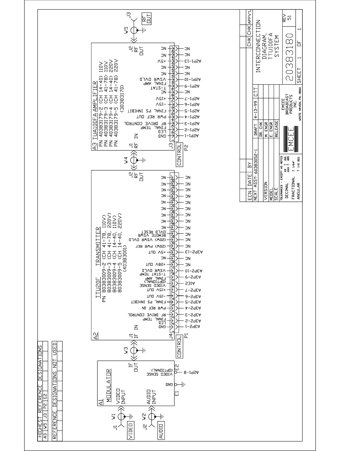
Interconnect Harness TTU100FA
Transmitter EMCEE/60383052-1
OR
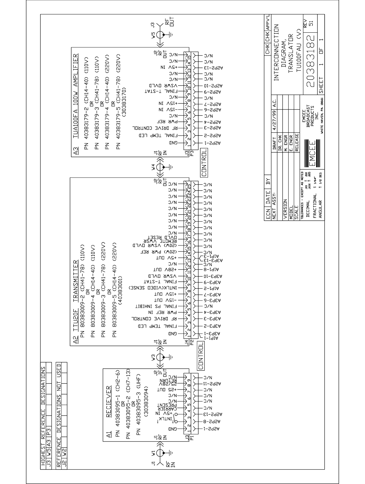
Interconnect Harness TU100FA Translator EMCEE/60383092-1
Surge Suppressor GE/V150LA10A E3, E4

SECTION V
SCHEMATIC DIAGRAMS
MODULE SCHEMATICS
ARE LISTED IN
ALPHANUMERICAL SEQUENCE