EMCEE Broadcast TTU500FA UHF LPTV Transmitter User Manual RF Communications 2000 Modulator Manual Cover wpd

EMCEE Broadcast Products UHF LPTV Transmitter RF Communications 2000 Modulator Manual Cover wpd

Contents

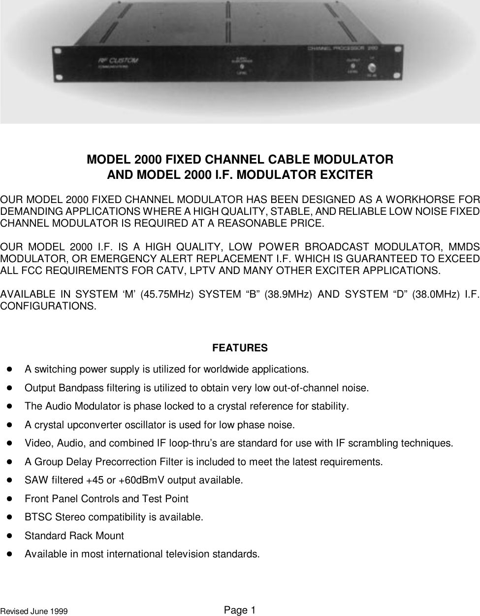
RF Commmunications Model 2000 Modulator Manual

Page 1Revised June 1999MODEL 2000 FIXED CHANNEL CABLE MODULATORAND MODEL 2000 I.F. MODULATOR EXCITEROUR MODEL 2000 FIXED CHANNEL MODULATOR HAS BEEN DESIGNED AS A WORKHORSE FORDEMANDING APPLICATIONS WHERE A HIGH QUALITY, STABLE, AND RELIABLE LOW NOISE FIXEDCHANNEL MODULATOR IS REQUIRED AT A REASONABLE PRICE.OUR MODEL 2000 I.F. IS A HIGH QUALITY, LOW POWER BROADCAST MODULATOR, MMDSMODULATOR, OR EMERGENCY ALERT REPLACEMENT I.F. WHICH IS GUARANTEED TO EXCEEDALL FCC REQUIREMENTS FOR CATV, LPTV AND MANY OTHER EXCITER APPLICATIONS.AVAILABLE IN SYSTEM ‘M’ (45.75MHz) SYSTEM “B” (38.9MHz) AND SYSTEM “D” (38.0MHz) I.F.CONFIGURATIONS.FEATURESA switching power supply is utilized for worldwide applications.Output Bandpass filtering is utilized to obtain very low out-of-channel noise.The Audio Modulator is phase locked to a crystal reference for stability.A crystal upconverter oscillator is used for low phase noise.Video, Audio, and combined IF loop-thru’s are standard for use with IF scrambling techniques.A Group Delay Precorrection Filter is included to meet the latest requirements.SAW filtered +45 or +60dBmV output available.Front Panel Controls and Test PointBTSC Stereo compatibility is available.Standard Rack MountAvailable in most international television standards.
Page 2Revised June 1999MODEL 2000 FIXED CHANNEL MODULATOR SPECIFICATIONS:(NORTH AMERICAN NTSC)1) MAXIMUM OUTPUT LEVEL +60dBmV2) SPURIOUS OUTPUTS 5-750MHz:  Less than  60dBc3) DIFFERENTIAL PHASE Less than 2 degrees4) DIFFERENTIAL GAIN Less than 3%5) VIDEO SIGNAL-TO-NOISE RATIO Better than 60dBc6) FREQUENCY RESPONSE TO 4.1MHz ±1dB7) GROUP DELAY PRECORRECTION ±50ns8) CHROMA-LUMA DELAY Less than ±50ns9) VISUAL CARRIER FREQ. TOL. ±500Hz or better10) AURAL CARRIER LEVEL 7 to  25dB below Video Carrier11) AURAL CARRIER FREQ. TOL. ±500Hz or better12) AUDIO RESPONSE 50 to 15kHz or ±1dB13) AUDIO DISTORTION Less than 0.2%14) AUDIO PRE-EMPHASIS 75 s Standard (flat, or 50 s opt)15) AUDIO INPUT Balanced or unbalanced, line level16) VIDEO INPUT 75 Ohms .5 to 2Vp-p17) AC POWER 85-260 Volts; 20 Watts 50-60Hz18) OUTPUT FREQ. US System M, PAL B, PAL D/K19) IF IMPEDANCE 75 Ohms20) STANDARD RACK MOUNT
Page 3Revised June 1999MODEL 2000TELEVISION MODULATORINTRODUCTION:The Model 2000 Television Modulator is designed for use in broadcast and other applications where highquality stable signals are required.  This unit, in the NTSC format, exceeds all Part 74 and 76 requirementsfor broadcast exciters.  This product is also available to meet most International standards.STANDARD FEATURES:1. 75 Ohm 1 volt p-p video input2. Baseband audio input usable balanced or unbalanced3. Utilizes SAW filter for high quality vestigial sideband output4. Low spurious and harmonic signals5. Many options available (consult factory)6. Meets applicable Group Delay characteristics7. Switching power supply for efficiency and wide voltage range — 85-265 volts 50-60Hz.  (Dc poweroptions also)8. Conservative design for long life and high reliabilityAVAILABLE OPTIONS:1. Audio subcarrier input for BTSC encoders that provide a subcarrier output.  This option is alsoprovided with switch selectable baseband audio (internal subcarrier oscillator/modulator) input forconventional use.2. Composite input (Audio subcarrier included with Video) for applications such as signals frommicrowave equipment.  This option is also provided with switch selectable baseband audio (internalsubcarrier oscillator/modulator) input for conventional use.3. Wideband audio input for BTSC stereo encoders that provide a baseband output.4. Separate audio and video carriers for use with separate aural and visual transmitter upconverter/amplifiers (one non-SAW filtered visual IF loop standard).5. Composite output containing both aural and visual carriers where one transmitter upconverter/amplifier is utilized.  Triple IF loops for testing or use with scrambling systems are standard (aural,visual and SAW filtered composite).6. Choice of output levels +45 or +60dBmV.7. Channelized output with user’s choice of carrier frequency.  (7 to 850MHz at +60dBmV level) (threeIF loops standard)8. Dc coupled video for use with many baseband scrambling systems.  (This option does not provideclamping, white clip or modulation depth indication for the video.)
MODEL 2000 TELEVISION MODULATORPage 4Revised June 19999. Slow clamping for certain baseband scrambling methods.We can provide many other optional configurations.  Contact factory for information.INSTALLATION:MOUNTING:This product is designed to be mounted in a standard EIA 19-inch wide rack.  Space should be left aboveand below the unit for ventilation.  A climate controlled room is ideal but proper operation will occur over awide range of operating conditions.  Depending upon other heat producing equipment in the rack, forced airventilation of the rack may be necessary to prevent excessive temperatures.  If the mounted unit will besubjected to severe mechanical shock, such as mobile use, the rear of the chassis should be supported.POWER:This product is equipped with a three-wire cord.  The third prong should not be removed or otherwisedefeated.  A SHOCK HAZARD COULD RESULT.  This product will operate properly from power sourcesalmost anywhere in the world, although some cautions are in order:1. Ac voltages of 85 to 265 volts and 50 to 60Hz only may be used.  If the voltage may exceed theabove maximum for even a short time, a step-down transformer or power line regulator isrecommended to reduce the maximum to well within the above range.2. Lightning and surge protection should be provided at the power entry of the building where thisequipment is installed.3. Proper grounding is important and should include bonding of racks together and connection of racksto a good earth ground.REAR PANEL CONNECTIONS:Audio:The audio input may be used balanced or unbalanced.The audio is connected through a three-pin quick connect plug.  To connect wiring pull the plug straight outfrom the rear of the unit.  With a small flat-bladed screwdriver, turn the screws counterclockwise to exposethe hole for the wire at the rear of the plug.  Strip the wire approximately 1/4 inch (7mm) and insert in theproper location of the plug.  Tighten the screw clockwise to secure the wire.  Reinsert the plug into thereceptacle on the rear of the modulator with the screw heads on the plug pointing up.A balanced line can be a simple twisted pair or may have a shield over a twisted pair.  The shielded line isto be preferred to reduce noise and RF pickup especially for longer length runs.For a balanced line, connect the two sides of the line to the + and   terminals.  The center ground pin maybe connected to the cable shield if present.  The center ground pin is connected to the chassis and, if humor noise due to a ground loop is experienced, try removing the ground connection to see if the condition
MODEL 2000 TELEVISION MODULATORPage 5Revised June 1999improves.  The input is configured as a bridging input and, if 600 ohm termination is required, an externalresistor may be connected between the + and   terminals on the plug.An unbalanced line must be a shielded cable except for very short runs of a few inches.  Hum and noisepickup is likely due to the lack of common mode rejection as provided by a balanced line.  The balanced lineshould be used wherever possible.For an unbalanced line, connect the center conductor of the shielded cable to the + terminal and the groundto the ground terminal.  The   terminal may be left unconnected or connected to the ground terminal by ashort piece of wire.Video:The video input is a standard 75 ohm “F” connector (BNC available as an option as are special terminatingimpedances).  This product is designed for sync negative video standard and a level of one volt p-p nominal.A signal between one half and two volts will allow adjustment to proper modulation depth however.A quality cable should be used for hookup.  Hum in the video may be reduced by heavy bonding strapsbetween racks and proper grounding.All video lines should be as short as practical.IF LOOP(S)The IF loop(s) may be used for IF scrambling, switching or other purposes requiring levels of +40dBmVnominal (video) at 75 Ohms.All units with separate aural and visual outputs will have one loop for the video IF; this loop is prior to theSAW filter so that any out-of-band spurious or harmonic products generated by external equipmentconnected in the loop will be eliminated by the SAW filter.Units with composite outputs will have three loops, one pre-SAW filtered video IF loop, one audio IF loop(level equal to video IF level minus the difference between the video and audio carriers), and a post SAWfiltered composite loop.IF OUTPUT(S):The main video IF output (or composite IF output) is a 75 Ohm “F” connector with a level of +45dBmVmaximum (up to +65dBmV available as an option).  A level control is available on the front panel which willallow reduction by a minimum of 20dB.  This output is also available with an output frequency of the user’schoice (internal upconverter and filters).The audio IF output (on products with separate outputs) will have a standard level of +40dBmV maximum(higher available as an option) with a front panel level control allowing a minimum of 20dB reduction.  Theaudio IF is bandpass filtered.
MODEL 2000 TELEVISION MODULATORPage 6Revised June 1999NOTE: All connectors are standard “F”, and mating connectors should be lightly wrench tightened andproperly crimped to the cable.CONTROLS:All operating controls and indicators are present on the front panel except for the audio select switch whichis located on the rear panel of products with certain audio options such as subcarrier inputs.FRONT PANEL CONTROLS AND INDICATORS (LEFT TO RIGHT):POWER INDICATOR:  located on the left side of the front panel.AUDIO:DEViation:  Screwdriver slotted control for setting the deviation of the audio carrier.  Clockwise increasesdeviation.OVERdeviation:  Red indicator which will illuminate to indicate excessive deviation of the audio carrier.Operation occurs at ±25kHz for NTSC (U.S.) or ±50kHz (most PAL).  Proper setup will allow brief flashingon the loudest portions of program material.  Setup can be verified with a spectrum analyzer or some signalstrength meters.VIDEO:MODulation:  Screwdriver slotted control for setting video modulation percentage (modulation depth).Clockwise increases modulation.OVERmodulation:  Red indicator which will illuminate to indicate excessive modulation.  NOTE:  The videosignal must contain significant amounts of peak white for an accurate reading to be obtained.  Monitoringthe signal with a picture monitor (television) while adjusting to make certain that the picture containssignificant white areas will assure reasonable adjustment.  Picture contrast can also be judged and examinedfor signs of overmodulation of peak whites.The most accurate means of setting video modulation is with a spectrum analyzer to set modulation depthto 87.5 percent (analyzer set to linear detector) or 18dB (with the analyzer set to log detector).  Some modernsignal strength meters are capable of reasonably accurate modulation measurement.AUDIO SUBCARRIER LEVEL:  Screwdriver slotted control for setting the level of the audio carrier (videocarrier to audio carrier ratio).  Clockwise rotation will increase the carrier thus reducing the ratio betweenvideo and audio.  This control is used to set the audio carrier output level on product without compositeoutputs.  Proper adjustment requires a spectrum analyzer or a calibrated tunable signal level meter.OUTPUT LEVEL:  Screwdriver slotted control for setting the composite output level for products so equippedor setting the video carrier level on products without a composite output.  Clockwise rotation increases theoutput level.  Proper adjustment depends on requirements of the equipment being driven.  Althoughadjustment range exceeds 20B, it is recommended in cases that require significant reduction of 10dB orgreater from the nominal rated output of the exciter that a fixed attenuator should be used instead of using
MODEL 2000 TELEVISION MODULATORPage 7Revised June 1999this control to reduce level.  This will maintain optimum signal-to-noise ratios.  Accurate adjustment requiresa spectrum analyzer or calibrated tunable signal strength meter.T.P.  20DB:  Test point used to monitor the composite output or video carrier output on units withoutcomposite outputs.  Nominal level is 20dB below the rear panel output.SHOULD REPAIRS BECOME NECESSARY:This product is covered by a one-year limited warranty on parts and labor.  Should repairs becomenecessary, factory service is recommended to restore this equipment to like-new operating condition.  Wehave the training, knowledge and experience to properly repair our products and in-stock parts availability.Our out-of-warranty repairs are usually faster and less costly than other repair centers and you are assuredof meeting original specifications.  Most products will be repaired within one week of receipt and will bereturned via the same shipping method used to send the unit to us.

Navigation menu