EMI Air Conditioner/heat Pump(outside Unit) Manual L0612425
User Manual: EMI EMI Air conditioner/heat pump(outside unit) Manual EMI Air conditioner/heat pump(outside unit) Owner's Manual, EMI Air conditioner/heat pump(outside unit) installation guides
Open the PDF directly: View PDF ![]() .
.
Page Count: 27
S1 C/S 1H SINGLE-ZONE
SIDE DISCHARGE J
i
E_l@ _ricaSgrigs
i
5780 Success Dr.
Rome, NY 13440
www.enviromaster.com

INSTALLATION,OPERATIONANDMAINTENANCEMANUAL
P/N240005897,Rev.1.2[05/06]
Thismanualisintendedasanaidtoaqualifiedservicepersonnelforproperinstallation,
operation,andmaintenanceofEMIAmericaSerieshighefficiency condensing units.
Carefully read these instructions before attempting installation or operation. Failure
to follow these instructions may result in improper installation, operation, service, or
maintenance, possibly resulting in fire, electrical shock, property damage, personal
injury, or death.
• _ D
(1) Retain this manual and warranty for future
reference.
(2) Before leaving the premises, review this
manual to be sure the unit has been
installed correctly and run the unit for
one complete cycle to make sure it
functions properly.
To obtain technical service or warranty
assistance during or after the installation
of this unit, check our website @ www.
enviromaster.com or call your installing
contractor or distributor. Our technical
service department may be contacted at
1-800-228-9364.
When calling for assistance, please have
the following information ready:
• Model Number
• Serial Number
• Date of installation
DANGER
'_' Read all instructions before using
the EMI AmericaSeries high ef-
ficiency condensing unit. Install or
locate this unit only in accordance
with these instructions. Use this
unit only for its intended use as
described in this manual.
,AY
Check the rating plate on the EMI
AmericaSeries condensing unit
before installation to make certain
the voltage shown is the same as
the electric supply to the unit.
The EMI AmericaSeries condens-
ing unit must be connected only to
a properly grounded electrical sup-
ply. Do not fail to properly ground
this unit.
Turn off the electrical supply before
servicing the EMI AmericaSeries
condensing unit.
Do not use the EMI AmericaSeries
condensing unit if it has damaged
wiring, is not working properly, or
has been damaged or dropped.
[Save These Instructions]
_'®D b " " •
The AmericaSeries SlC/H and $2C
condensing units are, air-cooled, vertically
arranged side discharge, high efficiency
units designed specifically to meet or ex-
ceed a 13 SEER rating.
The S1C 9,000-36,000 Btuh and S1H
9,000-24,000 Btuh capacity condensing unit
will provide cooling for a single evaporator,
as identified in the "S 1C Specifications and
Dimensions" section on pages 22-23.
The $2C 18,000 (99) - 21,000 (92) and
23,000 (22) Btuh capacity condensing units
will provide cooling for two evaporators, as
identified on page 24 in the "$2C Specifica-
tions and Dimensions" section. The S1C/H
and $2C are quiet units that can be recom-
mended for both commercial and residential
applications.
installation of the S1C/H and $2C
condensing units is simplified by a 24V
control interconnection from the evaporator
and multiple units can be lined up in close
proximity to an exterior wall. Service valves
are recessed to reduce tampering and
all 9,000-12,000 Btuh units are equipped
with a Duratec Performance Package that
includes an oversized suction accumula-
tor with surge baffles and enhanced oil
management, a factory installed solid core
filter drier and loss of charge switch. A field
installed crankcase heater is standard on
S1H 0-9 &12 models, and is available as
optional equipment on other models.
• Power wiring
• Low Volt wiring (18 awg minimum)
• Secure mounting pad or foundation
• Refrigerant piping (if not purchased
from EMI)
• High Volt Disconnect
• Refrigerant for charging interconnect
piping (see charge table on page 10)
• Compressor and fan motor contactor
• Run capacitor
• Loss of charge switch (09 - 12 only)
• Low voltage terminal connections
• Large capacity suction accumulator
(09 -12 only)
• Solid core filter drier (09 - 12 only)
• Crankcase heater (09 - 12 $1H's)
• H.RS. (High pressure switch)
- Standard on S1H's (heat pumps)
- Standard on SlC's 18K and above.
• Low Ambient controls for operation
down to 32 ° F standard, factory in-
stalled on all Sl H's (heat pumps)
j Q_ Q
• Field installed crankcase heater for
straight cool units (standard on 9,000-
12,000 Btuh S1H's)
• Straight cool hard start (standard on
all S1H's)
• 115V (9,000-12,000 Btuh only)
• Copper/copper coils (sea coast use)
• LowAmbient controls for operation down
to 32 ° F, specify this option for SlC or
$2C systems (standard on SlH's) that
will be operated in cooling mode at
outside temperatures below 60 ° F (field
installed kit)
• Low Ambient for operation down to 0° F
for SlC, S1H or $2C systems (consult
factory for availability)
Low Ambient controls are required when
the system is asked to cool at outdoor tem-
peratures below 60 ° F, this may cause dam-
age to the compressor and coil, and may
void the warranty. A Field Installed Low-
Ambient Kit is good for operation down to
32 ° F. This is accomplished by cycling the
condenser fan on and off, which will in turn
maintain a constant low side pressure pro-
viding a steady cooling effect and keeping
the air handler from frosting-up.
•Locatetheunitasclosetotheindoor
sectionas possible.(SeeTubing
Specificationschartonpape7.)
•Iftheunitisusedforlowambientcool-
ingdownto32°F,thisoptionmustbe
specifiedtopreventsystemdamage.
•Avoidhightrafficareasandprevailing
windlocations.
•Surfacemustbeflatandlevel.
• Mount unit above typical snow fall
levels.
Ensure free flow of air through the unit.
Air must not recirculate from discharge to
intake. Air is drawn through the coil and
side discharged through the fan grille. A
minimum 48" clearance is necessary for
the condenser discharge. Rear intake
(coil side) clearance is 12" minimum.
Consider how power will be run to the unit
from the power source. Refrigerant piping
should be a direct line to the indoor unit.
1. Place the unit on a flat concrete surface
or pad if on the ground. Roof mounting
should use a build up platform to avoid
intake of hot air from the roof.
2. in areas of heavy snowfall, condens-
ers should be set above the level of
maximum anticipated snowfall (12"
is usually adequate).
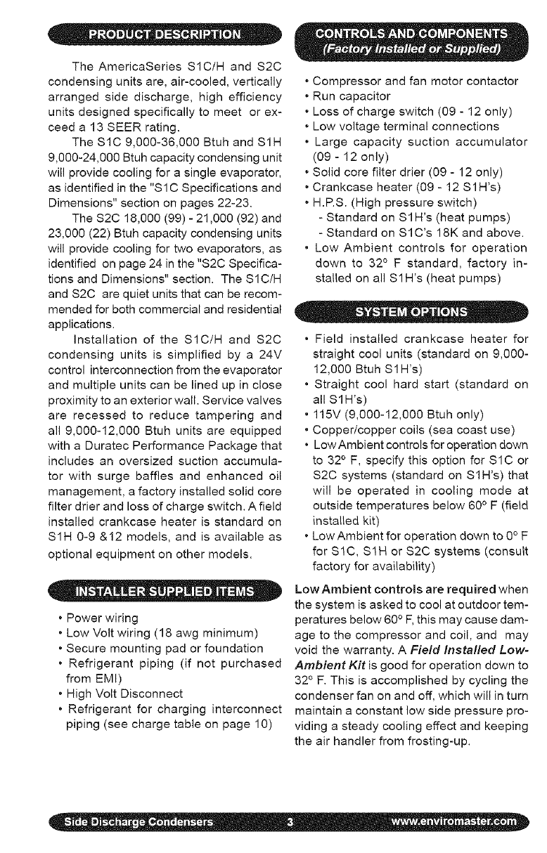
Side discharge unit allows for per-
manent mounting through the feet. This is
highly recommended due to the vertical
design of the unit.
1. Loosen the screws on left and right sides
of the front panel. (De not remove these
screws.)
2. Remove the screws on the front of the
panel.
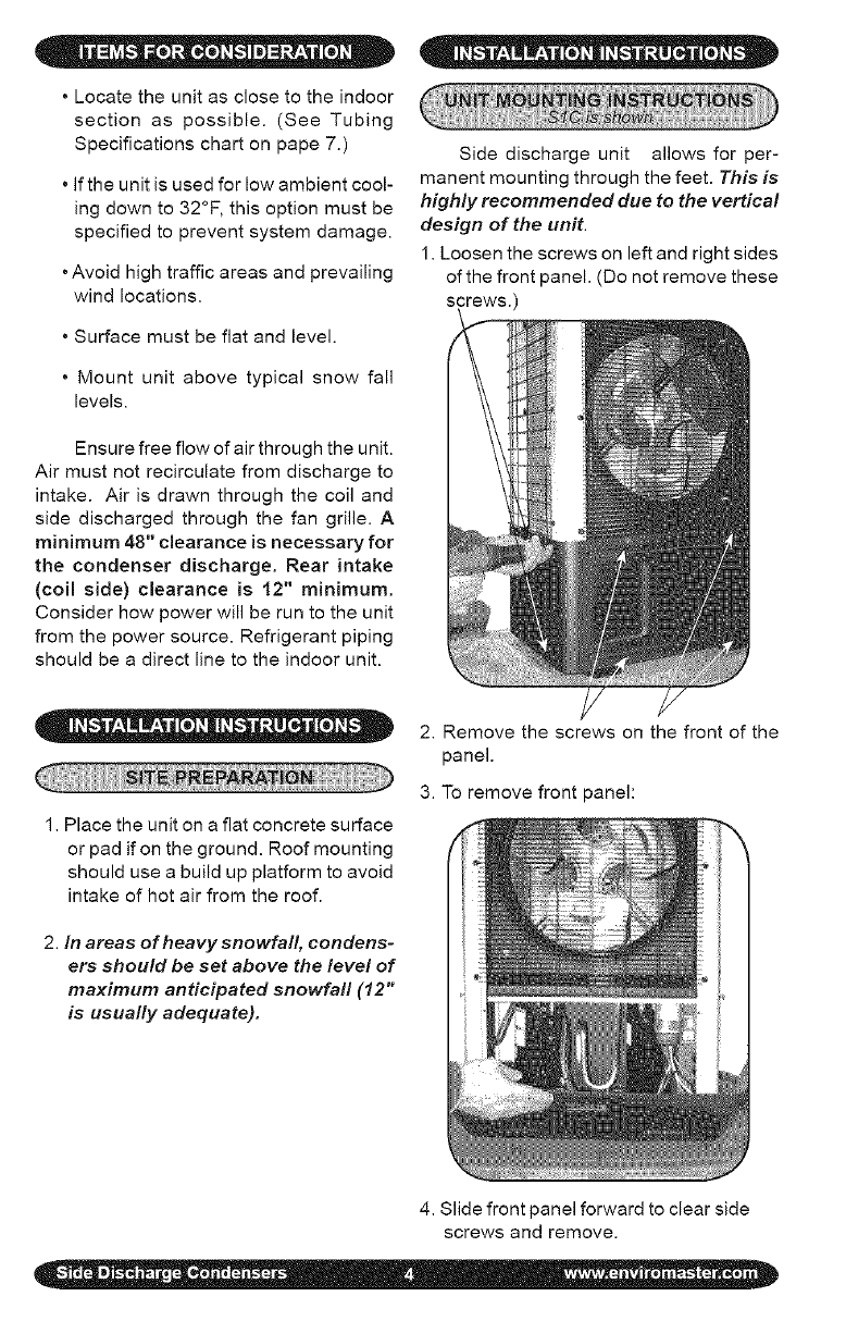
3. To remove front panel:
4. Slide front panel forward to clear side
screws and remove.
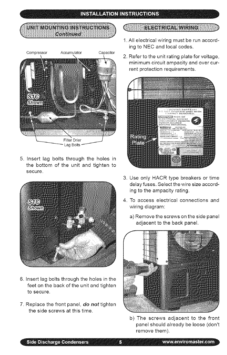
Compressor Accumulator Capacitor
Lag Bolts
1. All electrical wiring must be run accord-
ing to NEC and local codes.
2. Refer to the unit rating plate for voltage,
minimum circuit ampacity and over cur-
rent protection requirements.
5. Insert lag bolts through the holes in
the bottom of the unit and tighten to
secure.
3. Use only HACR type breakers or time
delay fuses. Select the wire size accord-
ing to the ampacity rating.
4. To access electrical connections and
wiring diagram:
a) Remove the screws on the side panel
adjacent to the back panel.
6. Insert lag bolts through the holes in the
feet on the back of the unit and tighten
to secure.
7. Replace the front panel, do not tighten
the side screws at this time.
b) The screws adjacent to the front
panel should already be loose (don't
remove them).
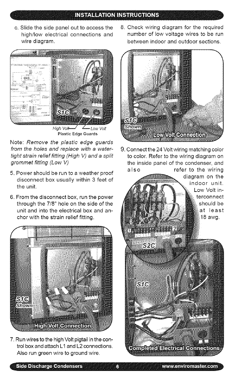
c.Slidethesidepanelouttoaccessthe 8.Checkwiringdiagramfortherequired
high/lowelectricalconnectionsand numberoflowvoltagewirestoberun
wirediagram, betweenindoorandoutdoorsections.
Hig Low Volt
Plastic Edge Guards
Note: Remove the plastic edge guards
from the holes and replace with awater-
tight strain relief fitting (High V) and a split
grommet fitting (Low V)
5. Power should be run to a weather proof
disconnect box usually within 3 feet of
the unit.
6. From the disconnect box, run the power
through the 7/8" hole on the side of the
unit and into the electrical box and an-
chor with the strain relief fitting.
7. Run wires to the high Volt pigtail in the con-
trol box and attach L1 and L2 connections.
Also run green wire to ground wire.
9. Connect the 24 Volt wiring matching color
to color. Refer to the wiring diagram on
the inside panel of the condenser, and
also refer to the wiring
diagram on the
indoor unit.
Low Volt in-
terconnect
should be
at least
18 awg.
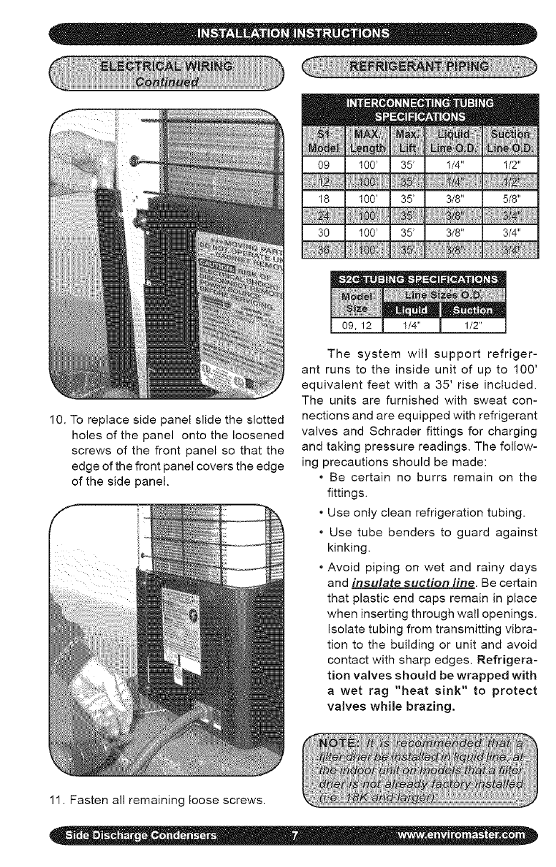
10.Toreplacesidepanelslidetheslotted
holesofthepanelontotheloosened
screwsofthefrontpanelsothatthe
edgeofthefrontpanelcoverstheedge
ofthesidepanel.
Thesystemwill supportrefriger-
antrunstotheinsideunitofupto 100'
equivalentfeetwitha35'riseincluded.
Theunitsarefurnishedwithsweatcon-
nectionsandareequippedwithrefrigerant
valvesandSchraderfittingsforcharging
andtakingpressurereadings.Thefollow-
ingprecautionsshouldbemade:
• Becertainnoburrsremainonthe
fittings.
•Useonlycleanrefrigerationtubing,
• Usetubebenderstoguardagainst
kinking.
•Avoidpipingonwetandrainydays
andinsulate suction line. Be certain
that plastic end caps remain in place
when inserting through wall openings.
Isolate tubing from transmitting vibra-
tion to the building or unit and avoid
contact with sharp edges. Refrigera-
tion valves should be wrapped with
a wet rag "heat sink" to protect
valves while brazing.
11. Fasten all remaining loose screws.
•A P-trap is recommended when the suc-
tion riser is equal to or greater than 20
feet in height.
• When the condenser is installed above
the evaporator, the P-trap will help the
return of oil back to the compressor.
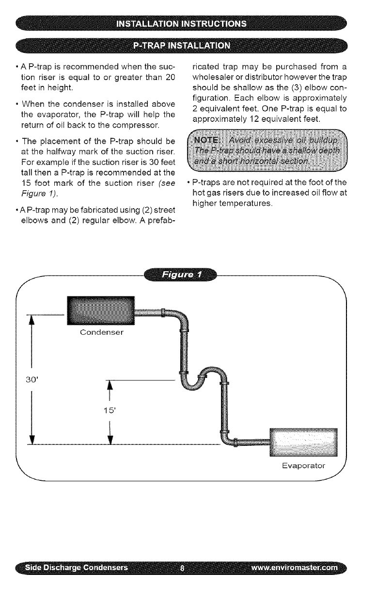
• The placement of the P-trap should be
at the halfway mark of the suction riser.
For example if the suction riser is 30 feet
tall then a P-trap is recommended at the
15 foot mark of the suction riser (see
Figure 1).
• A P-trap may be fabricated using (2) street
elbows and (2) regular elbow. A prefab-
ricated trap may be purchased from a
wholesaler or distributor however the trap
should be shallow as the (3) elbow con-
figuration. Each elbow is approximately
2 equivalent feet. One P-trap is equal to
approximately 12 equivalent feet.
• P-traps are not required at the foot of the
hot gas risers due to increased oil flow at
higher temperatures.
f
-- Condenser
Evaporator
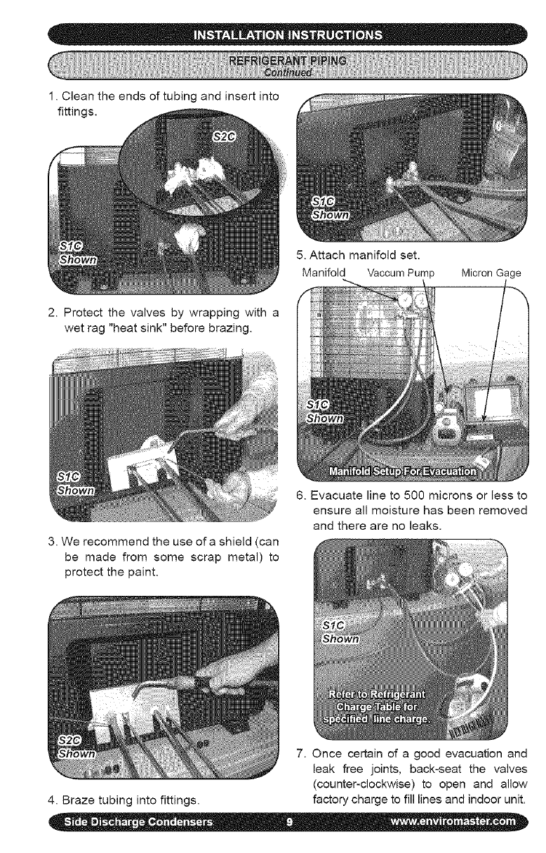
1.Cleantheendsoftubingandinsertinto
fittinc
5.Attachmanifoldset.
ManifoldVaccumPump MicronGage
2.Protectthevalvesbywrappingwitha
wetrag"heatsink"beforebrazing.
3.Werecommendtheuseofashield(can
bemadefromsomescrapmetal)to
protectthepaint.
6.Evacuatelineto500micronsorlessto
ensureallmoisturehasbeenremoved
andtherearenoleaks.
7.Oncecertainofa goodevacuationand
leakfreejoints,back-seatthevalves
(counter-clockwise)to openandallow
4.Brazetubingintofittings, factorychargetofilllinesandindoorunit.
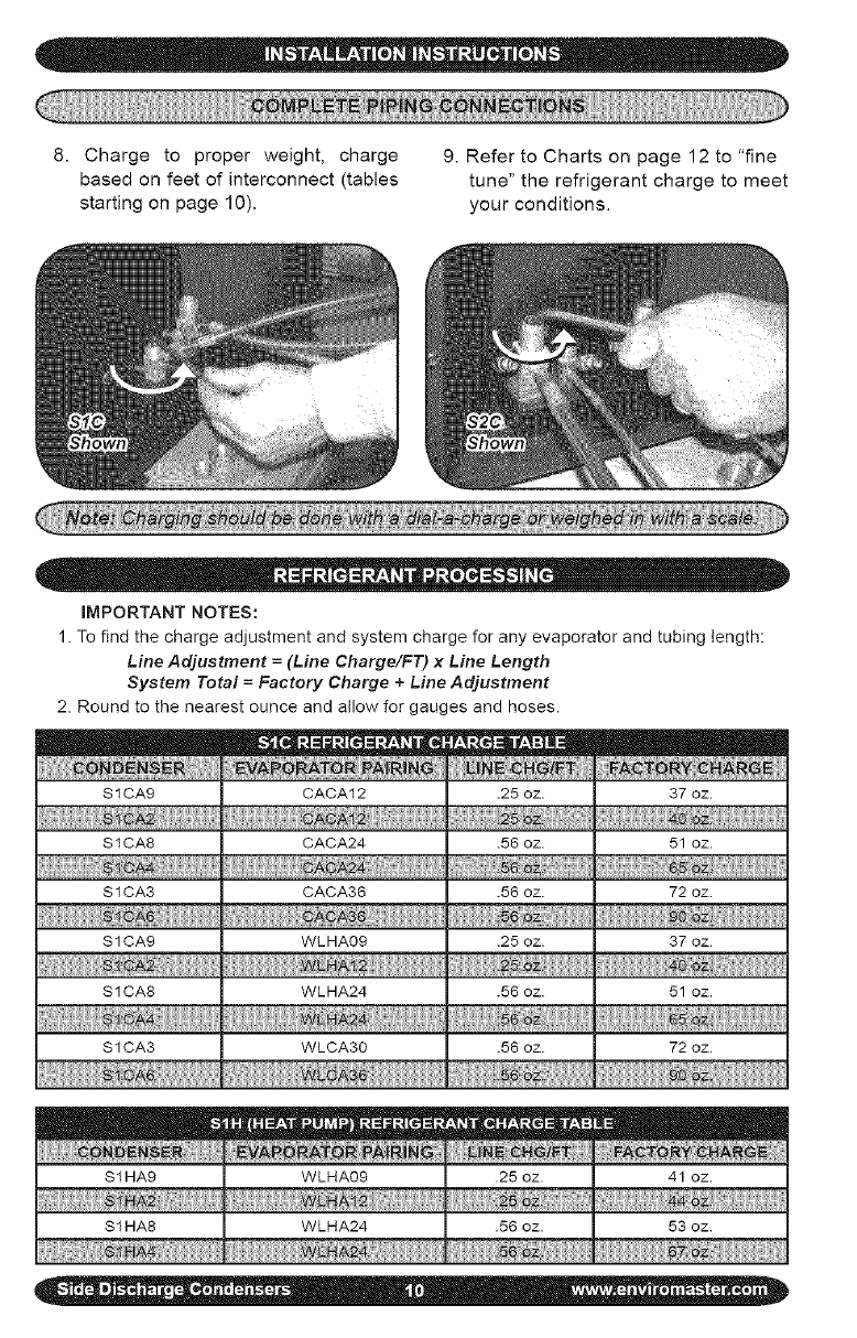
8. Chargeto properweight,charge
basedonfeetofinterconnect(tables
startingonpage10).
9.RefertoChartsonpage12to"fine
tune"therefrigerantchargetomeet
yourconditions.
IMPORTANTNOTES:
1.Tofindthechargeadjustmentandsystemchargeforanyevaporatorandtubinglength:
Line Adjustment =(Line Charge/FT) x Line Length
System Total =Factory Charge +Line Adjustment
2. Round to the nearest ounce and allow for gauges and hoses.
S 1CA9 CACA12 .25 oz. 37 oz.
SICA8 CACA24 .56 oz. 51 oz.
S 1CA3 CACA36 .56 oz. 72 oz.
$1 CA9 WLHA09 .25 oz. 37 oz.
1i z.i
SICA8 WLHA24 .56 oz. 51 oz.
$1 CAg WLCAg0 .56 oz. 72 oz.
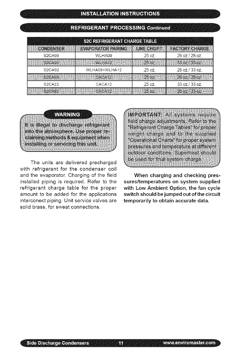
$2CA99 WLHA09 .25 oz. 28 oz./28 oz.
$2CA92 WLHA09+WLHA12 .25 oz. 28 oz./33 oz.
S2CA22 CACA12 .25 oz. 33 oz./33 oz.
ills2
The units are delivered precharged
with refrigerant for the condenser coil
and the evaporator. Charging of the field
installed piping is required. Refer to the
refrigerant charge table for the proper
amount to be added for the applications
interconect piping. Unit service valves are
solid brass, for sweat connections.
When charging and checking pres-
sures/temperatures on system supplied
with Low Ambient Option, the fan cycle
switch should be jumped out of the circuit
temporarily to obtain accurate data.
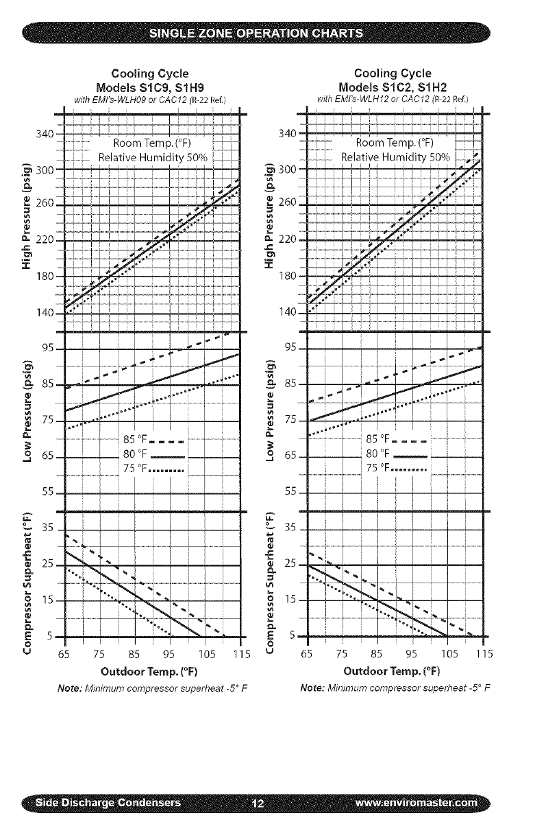
CoolingCycle
Models$1C9,$1H9
with EMI's-WLH09 or CAC12 (R-22 Ref.)
Cooling Cycle
Models $1C2, $1H2
with EMI's-WLHf2 or CAC12 (R-22 Ref.)
Room Temp. (°F)
Relative Humidity 50% "_ 300
._ .,c
85 °F.... ......................................................
380°F _L 3
Room Temp. (°F)
Relative Humidity 50%
,4
it
WL i................
....i"" i
...............................................................85 °F.... .......................................................
__ __ 80 °F
75 °F......... --
.....................i.................
o... 35 _ 35
o.
o o
u u
65 75 85 95 105 115 65 75 85 95 105 115
Outdoor Temp. (°F) Outdoor Temp. (°F)
Note: Minimum compressor superheat -5° F Note: Minimum compressor superheat -5° F
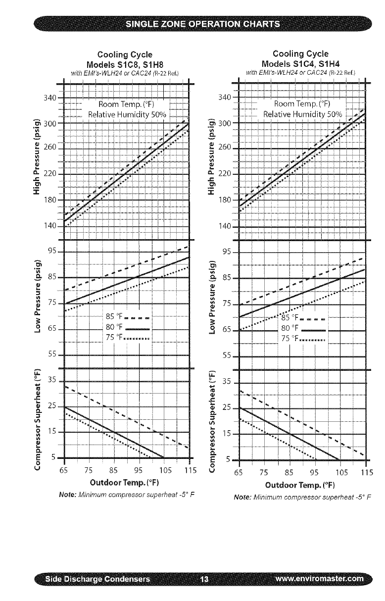
Cooling Cycle
Models SLC8, $1H8
with EMILe-WLH24 or CAC24 (R-22 Ref.)
340 Z
Room Temp. (°F)
Relative Humidit'
;i
.................h
_ 85
_80
7s
..................i....................................
3
Cooling Cycle
Models $1C4, SIH4
with EMI's-WLH24 or CAC24 (R-22 Ref.)
O_ 351 _° 35
15. ,. _ 15
5 I_ 5,
o0
v 65 75 85 95 105 115 _ 65 75 85 95 105 115
Outdoor Temp. (°F) Outdoor Temp, (°F)
Note: Minimum compressor superheat -5 ° F Note: Minimum compressor superheat -5° F
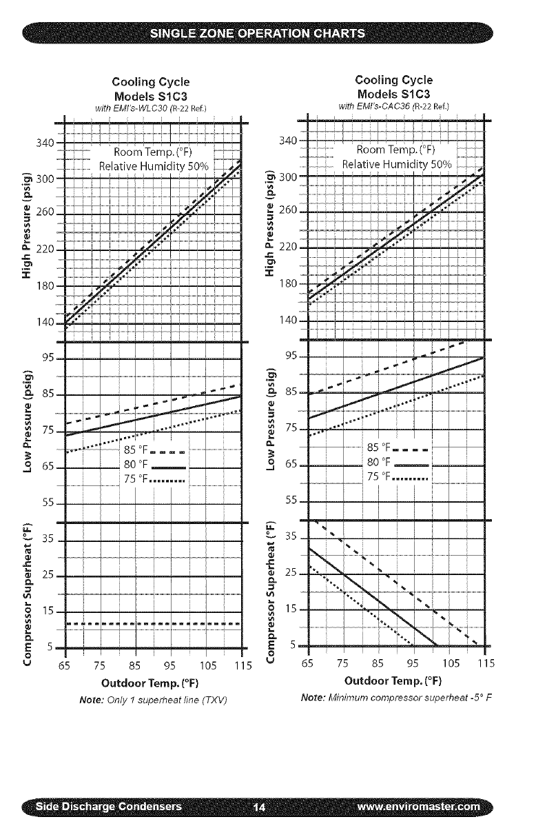
Cooling Cycle
Models SlC3
withEMI's-WLC30(R-22 Ref.)
Cooling Cycle
Models $1C3
withEMI's-CAC36(R-22 Ref.)
Room Temp. (°F)
Relative Humidity 50% 300
z I 1
._
:,_.- "_'_ '.,- 75-
o J 80 °F -- 3
7s°F.........
o 35
_, 25,
E
o
.....................i................. 55 r --
im_mmiim,_m
35.
i
1
i o 15-
..... o=- ..
E 5
o
65 75 85 95 105 115
Outdoor Temp. (°F)
Note: Only 1 superheat line (TXV)
Room Temp. (°F)
Relative Humidity 50%
i÷
..................85 °F.... ................
80 °F
i 75 °F......... ...................
i i ,
"'J i
65 75 85 95 105 115
Outdoor Temp. (°F)
Note: Minimum compressor superheat -5° F
340 _
___300
&
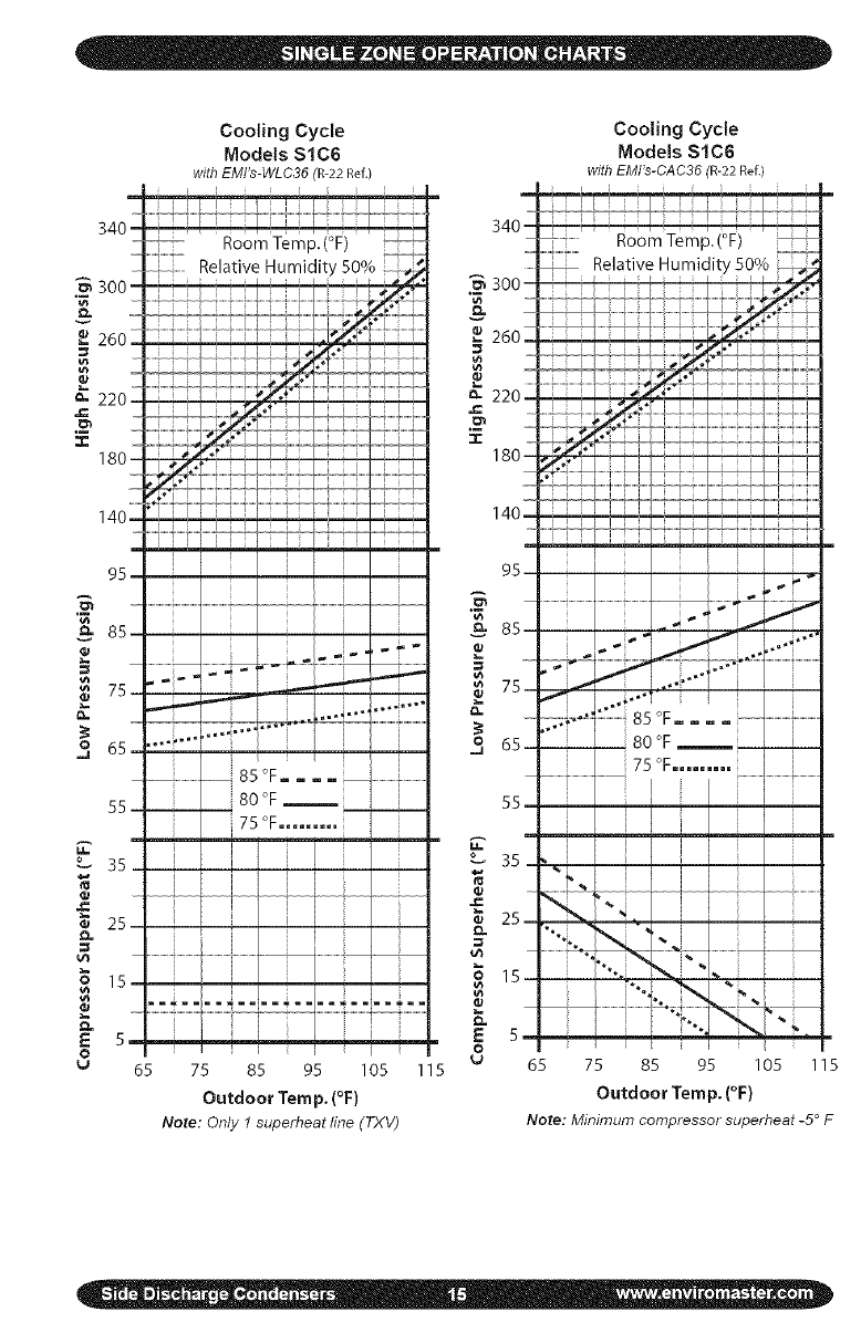
Cooling Cycle
Models $1C6
with EMI's-WLC36 (R-22 Ref.)
Room Temp.(°F)
Relative 50%
i
35
E
o
u
85 OF........................... i..................
- 80 °F i
75 °F..........
i I i
'i
i _ i
ii i
i
i I
65 75 85 95 105 115
Outdoor Temp. (°F)
Note: Only 1 superheat line (TXV)
Cooling Cycle
Models $1C6
with EMI's-CAC36 (R-22 Ref.)
i J
5: .................
.< ......................
65 75 85 95 105 115
Outdoor Temp. (°F)
Note: Minimum compressor superheat -5 ° F
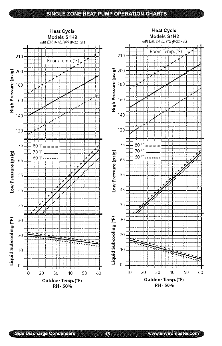
Heat Cycle
Models $1H9
with EMI's-WLH09 (R-22 Ref.)
Heat Cycle
Models $1H2
withEMI's-WLH12(R-22 Ref.)
10 20 30 40 50
Outdoor Temp. {°F}
RH -50%
60 10 20 30 40 50 60
Outdoor Temp. (°F)
RH -50%
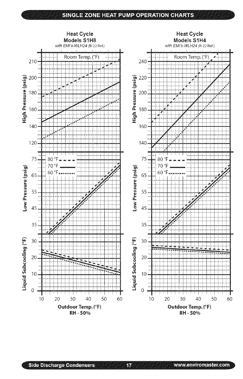
Heat Cycle
Models $1H8
withEMI's-WLH24(R-22 Ref.)
Heat Cycle
Models $1H4
withEMILs-WLH24(R-22 Ref.)
Room Temp.(°F)
10 20 30 40 50
OutdoorTemp.(°F)
RH-50%
60 I0 20 30 40 50 60
Outdoor Temp, (°F)
RH - 50%
m
34ol
3oo-
2602
_-220 Z
"1- 180Z
140L
95
"_ 85
_75-
3 65_
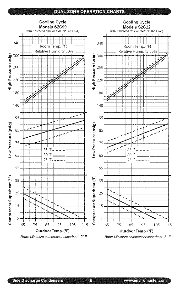
Cooting Cycle
Models S2C99
withEMFs-WLC09or CAC'i2(R-22 Ref./
......... ........ i
Room Temp.(°F) " '
1 Relative Humidity 50%
[ i [ i i ; i i ;s
......i...............................
[ i i _ ,i
i 1
I I
...... ....................................................................................i
....4-.....
..........._ ..................f 8soF....
___80 F
55
m
35
_ 25-
o.
E 5-
o
I
I
65 75 85 95 105 115
Outdoor Temp. (°F)
Note: Minimum compressor superheat -5 ° F
_m3oo
g
I1
Cooling Cycle
Models $2C22
withEMI's-WLC12or CAC'i2(R-22 Ref.)
Room Temp.(°F)
Relative Humidity 50%
=, _i..'"
7s- ......""'-',......................................,i...................
o. :- !85°F.= ......................................
3 -- _ 80 °F
175 °F......... ..................
55.
35,
,._ ,,.[ ....................
_ 15-
_ 5
o
u65 75 85 95 105 115
Outdoor Temp. (°F)
Note: Minimum compressor superheat -5° F
• In low ambient cooling 9-12 Btuh units,
if a crankcase heater is installed,
power the system 24 hours before
attempting to start the unit in cool
weather (below 60 ° F).
• After doing a final system check using
the Operation Charts (supplied on pre-
vious pages). Record results on Test
Unit Data Sheet on page 25.
• Remove gauge set. Mount all access
panels and make sure they are prop-
erly secured.
• Make final visual inspection and repair
any deficiencies.
The $1C/H and $2C outdoor sections
are the compressor bearing units of the
system. It operates at the command of
the indoor section or room thermostat.
Therefore, the system operation will be
described in the manual pertaining to the
indoor section.
EMI units are designed and con-
structed for reliability and long life with
minimal maintenance. You can assure
peak operating efficiency by regularly
inspecting for free air passage into and
through the coil. If debris collects on the air
coil, it should be cleaned by "back-flushing"
with a spray of water or vacuuming. TURN
OFF POWER SUPPLY FIRST. Outdoor
units may be cleaned or waxed if desired.
Use a non-abrasive car wax (on metal
surfaces only).
This unit is equipped with a perma-
nently lubricated motor. Although oiling is
not necessary, adding a few drops through
the oiling ports twice yearly will extend the
life of the motor. Do not over oil.
Panels should remain on the unit at all
times. Service should be performed by a
QUALIFIED service agency only.
All EMI products are subject to on-
going development programs so design
and specifications may change without
notice. Please consult the factory for more
information.
EMI America Series condensers are
designed to operate with EMI America
Series evaporators. Both the condenser
(outdoor unit) and evaporator (indoor
unit) have a high volt service connection.
Each is to be independently connected to
the electrical service panel. (See the unit
name plate for the correct breaker type
and size). The outdoor and indoor units
are also connected to each other through
a low volt interconnect wiring. A 24V trans-
former located in the indoor unit provides
the low Volt power source.
Straight cool condensers are designed
to operate as a single stage cooling unit.
Heat pump condensers are designed to
operate as a single stage cooling two
stage heating unit. For proper operation
the unit must be matched with an appro-
priate EMI indoor unit with unit mounted
controls and/or wall mounted thermostat.
For two-stage heating operation the in-
door unit must be equipped with an elec-
tric strip heater.
,j_%4_Condenser operation: The transform-
er located in the indoor unit provides 24V,
low-Volt control power to the condenser
(outdoor unit). This can be measured
across low-Volt terminals "R" and "C".
Single zone heat pump condensers
utilize a reversing valve to provide re-
verse cycle operation. Therefore the out-
door unit will act as either a condenser or
an evaporator there-by providing comfort
cooling or heating to the indoor space.
The reversing valve is energized in cool-
ing. Should the valve fail to actuate, the
system will default to the heating mode of
operation.
_Cooling operation, single-zone and
dual-zone: Cooling operation requires that
the control (either unit mount or remote
wall mount thermostat) make a connec-
tion between low-Volt terminals "R" and
"Y" along with "R" and "O" (heat pumps
only). When the indoor control is placed
in cooling mode, with the set point tem-
perature below the room temperature, the
reversing valve will energize (R & Oheat
pumps only) along with the compressor
and outdoor fan (R & Y). When the indoor
control is satisfied and the room tempera-
ture falls below the set temperature, the
compressor and fan will de-energize. The
anti-short cycle timer (ASCT) will prevent
the compressor from re-starting for three
minutes.
_Heating operation (heat pumps only):
Heating operation requires that the con-
trol (either unit mount or remote wall
mount, heat pump thermostat) make a
connection between low-Volt terminals
"R" and "Y" only. When the indoor control
is placed in heating mode, with the set
point temperature above room tempera-
ture, the compressor and outdoor fan
(R & Y) will energize. When the indoor
control is satisfied and the room temper-
ature rises above the set temperature,
the compressor and fan will de-energize.
The anti-short cycle timer (ASCT) will
prevent the compressor from re-starting
for three minutes.
_Y Defrost controls with short cycle
protection (heat pumps only): The unit
is equipped with a logic control circuit de-
signed to keep system operating at peek
efficiency. The 24V circuit provides control
to the indoor and outdoor systems includ-
ing a three minute, anti-short cycle timer
(ASCT) compressor protection.
The defrost control circuit is designed
to keep the condenser coil free from frost
and ice during heating mode. This is ac-
complished through the precise switching
sequence of the outdoor fan, reversing
valve and indoor auxiliary heater.
Jt_ Defrost initiation: The defrost-sensor
is located on either the end plate or the re-
turn bend of the condenser coil. A defrost
cycle will initiate after the sensor closes
(approx. 30 ° F) and remains closed for
the length of time selected on the control
board (either 30, 60 or 90 minutes)*.
At the start of the defrost cycle, the re-
versing valve will change from heating to
cooling mode. The condenser fan will also
switch off there-by allowing pressure and
temperature to rise within the condenser
coil to melting off any ice build-up. At the
same time the unit will switch on the in-
door electric strip heater to temper the
cold air being discharged from the evapo-
rator unit. This will continue until either
the defrost-sensor opens (approx. 60 ° F)
or a 10-minute maximum cycle time has
elapsed. Defrost times will vary depend-
ing on outdoor temperature and moisture
conditions. When the defrost cycle is com-
plete the unit will return to normal heating
operation.
*Factory settings 9-30/{ Btu =90 min-
utes, 36k Btu =60 minutes
The condenser will operate in heat-
ing for approximately 20 seconds. At that
point the unit will enter defrost mode for
approximately 2 seconds. During this time
the condenser fan will switch off, the re-
versing valve will energize and the defrost
board will energize the indoor electric
heat relay through the "W" terminal. After
the two second defrost cycle is complete,
the unit will switch back to heating opera-
tion for another 20 seconds. This process
will repeat until the jumpers are removed
from the test pins.
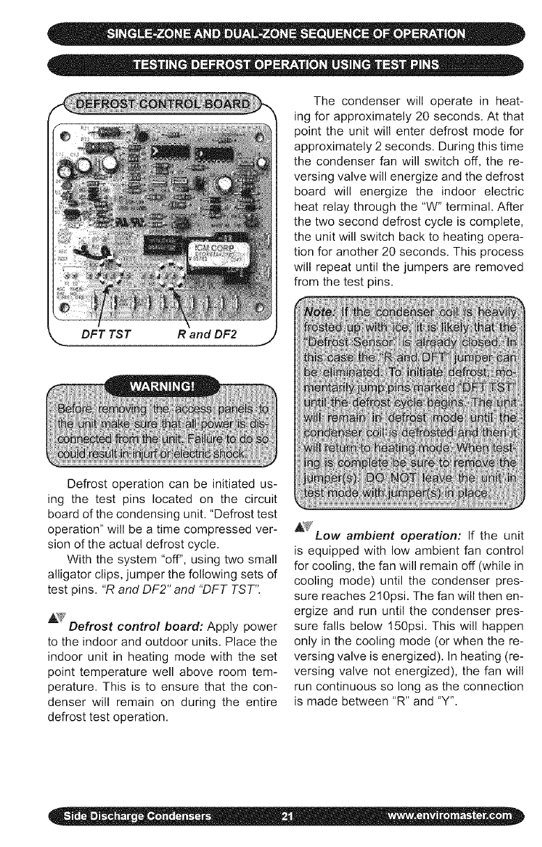
DFT TST Rand DF2
Defrost operation can be initiated us-
ing the test pins located on the circuit
board of the condensing unit. "Defrost test
operation" will be a time compressed ver-
sion of the actual defrost cycle.
With the system "off", using two small
alligator clips, jumper the following sets of
test pins. "R and DF2" and "DFT TST'.
AV Defrost control board: Apply power
to the indoor and outdoor units. Place the
indoor unit in heating mode with the set
point temperature well above room tem-
perature, This is to ensure that the con-
denser will remain on during the entire
defrost test operation.
_" Low ambient operation: If the unit
is equipped with low ambient fan control
for cooling, the fan will remain off (while in
cooling mode) until the condenser pres-
sure reaches 210psi. The fan will then en-
ergize and run until the condenser pres-
sure falls below 150psi. This will happen
only in the cooling mode (or when the re-
versing valve is energized). In heating (re-
versing valve not energized), the fan will
run continuous so long as the connection
is made between "R" and "Y'.
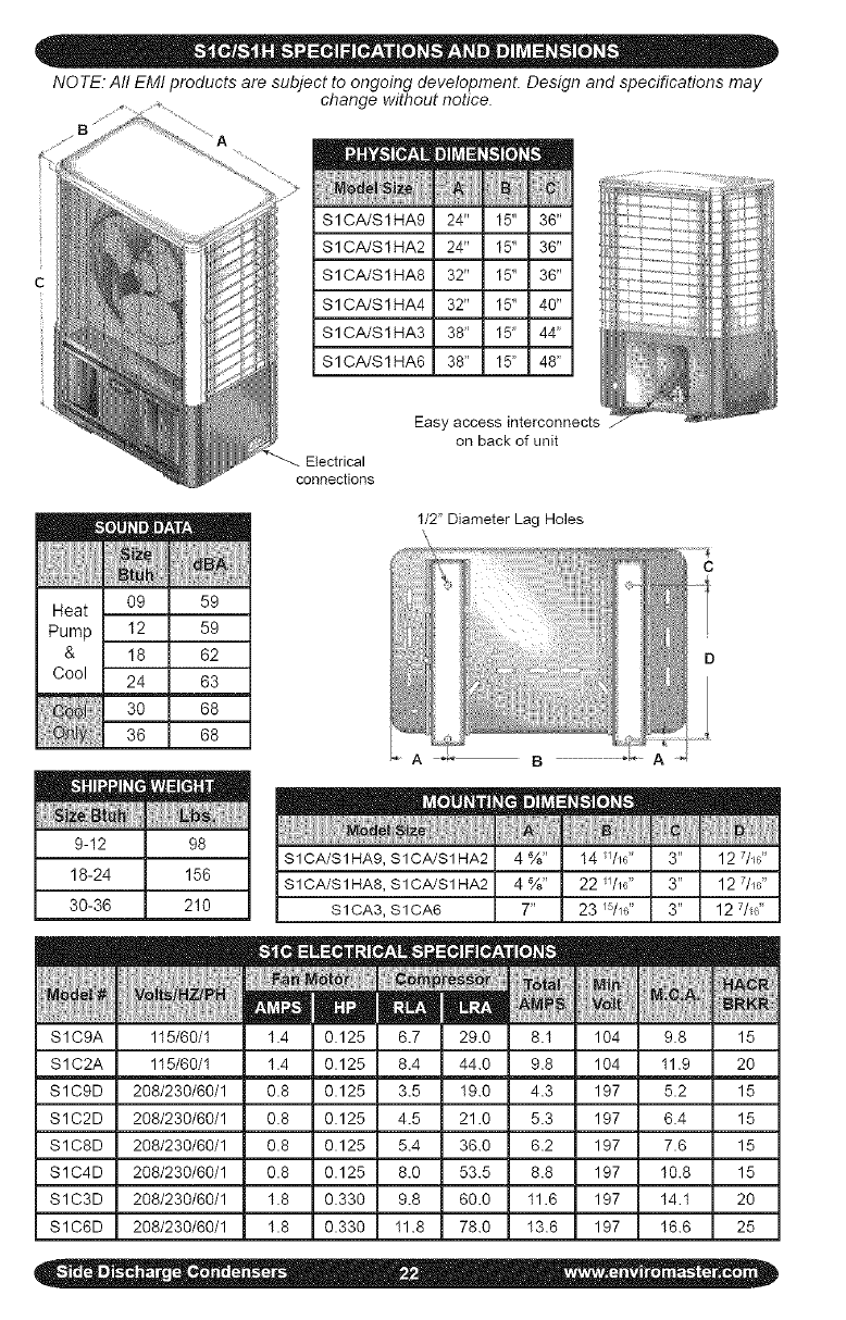
NO TE. All EMI products are subject to ongoing development. Design and specifications may
change without notice•
B
SlCA/SlHA9 24"
SlCA/SlHA2 24"
SlCA/SlHA8 32"
SlCA/SlHA4 32"
SlCA/SlHA3 38"
SlCA/SlHA6 38"
Zl
_iii/
5" 36"
5" 36"
5" 36"
5" 40"
5" 44'_
5" 48'_
W_
_9
I2
I8
->4
30
}6
m
BAI
_9
_9
)2
)3
)8
)8
Electrical
connections
Easy access interconnect. _
on back of unit
1/2' Diameter Lag Holes
9-12 98
18-24 156
30-36 210
SICA/S1 HA9, SICA/S1 HA2
SICA/S1 HA8, SICA/S1 HA2
SICA3, SICA6
|m
t ............
/ol_ 1}
104
LlO4
I 197
197
[O_a| ;;;;
_MP_]
8.1
4.3
5.3
6.2
8.8
11.6
13.6
115/60/1
115/60/1
208/230/60/1
208/230/60/1
208/230/60/1 197
208/230/60/1 197
208/230/60/1 197
208/230/60/1 197
m
9.8
11.9
5.2
6.4
7.6
10.8
14.1
16.6
m
15
2o
15
15
15
15
2O
25
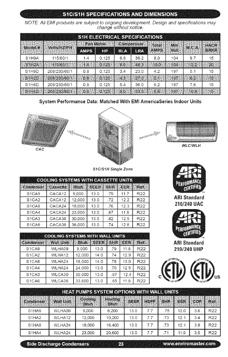
NOTE: All EMI products are subject to ongoing development. Design and specifications may
change without notice.
N{_i
vol_;
StH9A .O 104 9.7 15
S1H9D .2 197 5.1 15
SIH8D .2 197 7.6 15
System Performance Data: Matched With EMI AmerioaSeries Indoor Units
OAC
SIC/SIH Single Zone
SICA9 CACA12 9,000 13.0 .79 11.7 R22
SICA2 CACA12 12,000 13.0 .72 12.2 R22
S1CA8 CACA24 18,000 13.0 .76 12.3 R22
SICA4 CACA24 23.000 13.0 .67 11.8 R22
S1CA3 CACA36 30,000 13.5 .82 12.5 R22
SICA6 CACA36 36,000 13.0 .74 12.6 R22
eo *
S1CA9
S1CA2
S1CA8
S1CA4
S1CA3
SICA6
S 1HA9
S 1HA2
S 1HA8
S 1HA4
WLHAO9 9,000 13.0 .79 11.8 R22
WLHA12 12,000 14.0 .74 12.9 R22
WLHA24 18,000 14.0 .78 13.0 R22
WLHA24 24,000 13.0 .70 12.5 R22
WLCA30 30,000 13.0 .67 12.4 R22
WLCA36 33,600 13.0 .65 11.8 R22
NNPF
WLHA09 9,000 8_200 13. I 7.7
WLHA12 12,000 10,200 13. I 7.7
WLHA24 18,000 16,400 13. _ I7.7
I
WLHA24 23,000 20,600 13. } I7.7
I
WLC/WLH
5 12.C R22
12.1 R22
12.1 R22
1 11._ R22
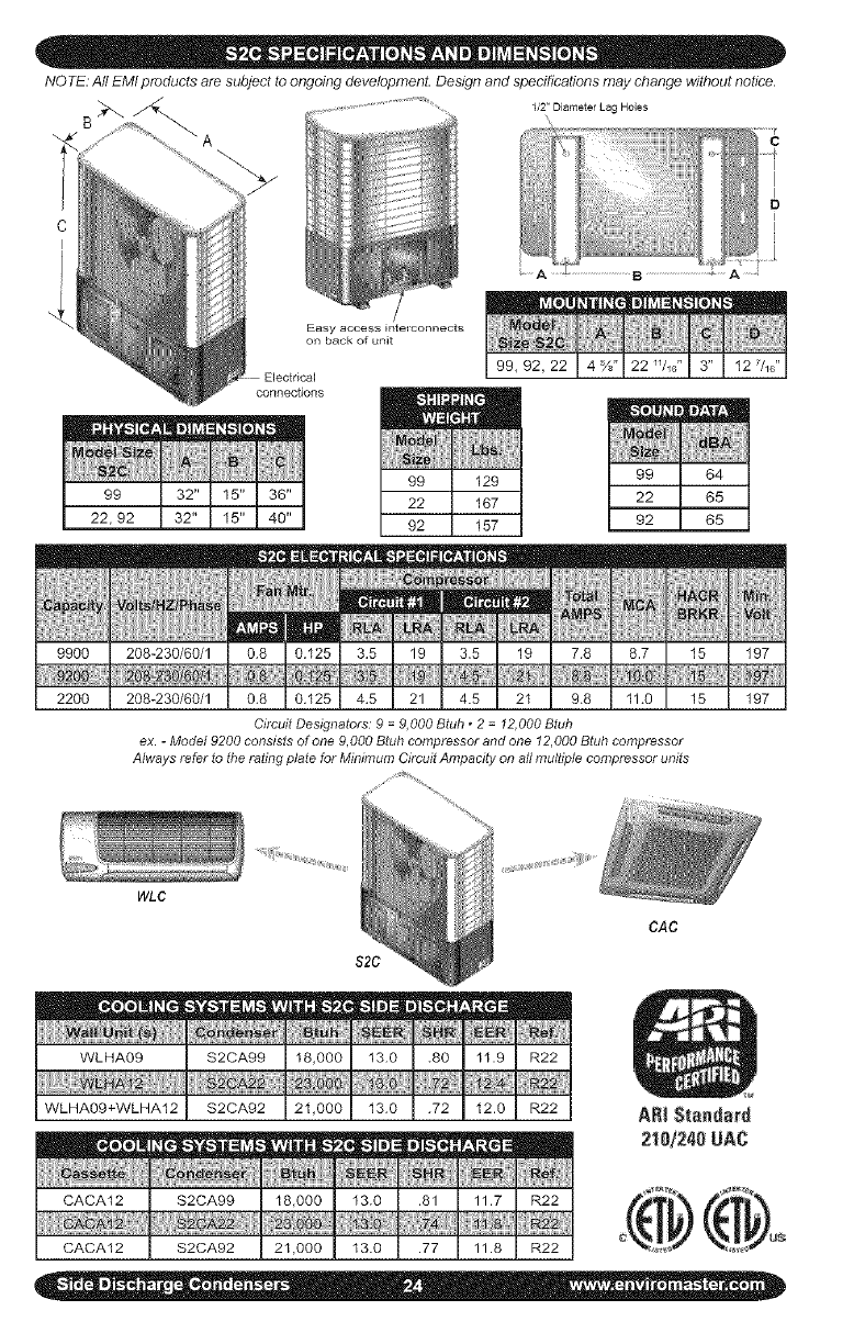
NOTE: All EMI products are subject to ongoing developmenL Design and specifications may change without notice.
1/2_'DiameterLag Holes
B
iiif !!!iiiiiiiiiiiiiif_! i
?D
..............................B...............................
Easy access interconnects
on back of unit
connections
99,92,22
99
22,92
!
9900
2200
208-230/60/1
208-230/60/1
! []
.....78 7
!!
HACR ;Mi_
11volt
197
15 197
Circuit Designators' 9 =9,000 Btuh * 2 = 12,000 Btuh
ex. - Model 9200 consists of one 9,000 Btuh compressor and one 12,000 Btuh compressor
Always refer lo lhe rating plale for Minimum Circuit Ampacily on all multiple compressor units
8RKR
15
WLC
S2C
CAC
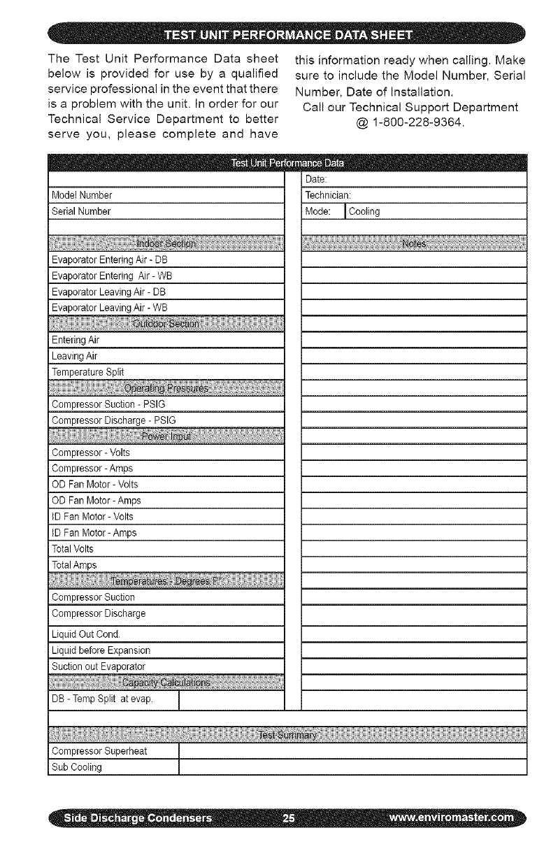
The Test Unit Performance Data sheet
below is provided for use by a qualified
service professional in the event that there
is a problem with the unit. In order for our
Technical Service Department to better
serve you, please complete and have
this information ready when calling. Make
sure to include the Model Number, Serial
Number, Date of Installation.
Call our Technical Support Department
@ 1-800-228-9364.
i ModelNumber
Serial Number
Date:
Technician:
Mode: ICooling
EvaporatorEnteringAir- DB
EvaporatorEnteringAir - WB
i EvaporatorLeavingAir - DB
i EvaporatorLeavingAir - WB
EnteringAir
i LeavingAir
TemperatureSplit
iCompressor Suction - PSIG
Compressor Discharge - PSIG
iCompressor - Volts
Compressor - Ampe
OD Fan Motor- Volts
OD Fan Motor- Amps
IDFan Motor- Volts
IDFan Motor-Amps
TotalVolts
Compressor Suction
Compressor Discharge
Liquid Out Cond
Liquid before Expansion
Suction out Evaporator
DB - Temp Split at evap.
I
CompressorSuperheat
SubCooling
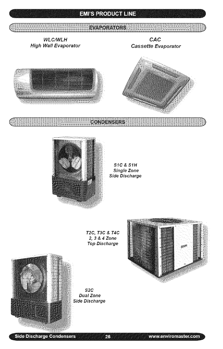
WLC/WLH
High Wall Evaporator
CAC
Cassette Evaporator
SIC& SIH
Single Zone
Side Discharge
T2C, T3C & T4C
2, 3 & 4 Zone
Top Discharge
$2C
Dual Zone
ALL PRODUCT LIMITED WARRANTY
Enviromaster International LLC (EMI) warrants to the purchaser/owner that EMI prod- I|
ucts will be free from defects in material and workmanship under the normal use and I|
maintenance for a period of twetve months for all components and sixty months on unit I|
compressors from the date of original installation, or fifteen months for all components I|
and sixty-three months on unit compressors from the date of manufacture, whichever I|
comes first. II
WHAT WE WILL COVER I|
EMI will replace any defective part returned to EMI's approved service organization with I|
a new or rebuilt part at no charge. The replacement part assumes that unused portion I|
of this warranty. I_
I!
WHAT WE DON'T COVER I|
THIS WARRANTY DOES NOT INCLUDE LABOR or other costs incurred for repairing, I|
removing, installing, shipping, servicing, or handling of either defective or replacement I|
parts. II
EMI IS NOT RESPONSIBLE FOR: I|
•Normal maintenance I|
• Damage or repairs required as a consequence of faulty installation or application by I|
others. I|
• Failure to start due to voltage conditions, blown fuses, open circuit breakers, or other I|
damages due to the inadequacy or interruption of electrical service. I|
•Damage or repairs needed as a consequence of any misapplication, abuse, improper I|
servicing, unauthorized alteration, or improper operation. I|
• Damage as a result of floods, winds, fires, lightening, accidents, corrosive atmosphere, I|
or other conditions beyond the control of EMI. I|
•Parts not supplied or designated by EMt. I|
• Products installed outside the United States or Canada. I|
•Any damages to person or property of whatever kind, direct or indirect, special or I|
consequential, Whether resulting from use or loss of use of the product. I_
III
LIMITATION OF WARRANTIES I|
This warranty is exclusive and in lieu of any implied warranties of merchantability and I|
fitness for a particular purpose and all other warranties express or implied. The remedies I|
provided for in this warranty are exclusive and shall constitute the only liabilities on the part I|
of EMI including any statements made by any individual which shall be of no effect. I
II
FOR SERVICE ul'_ I'(=r'_lK: I|
(1) Contact the Installer Enviromaster International LLC II
(2) Call the nearest Distributor 5780 Success Drive, Rome, NY 13440 II
(3) Contact the Factory www.enviromaster.com|
