EMI Air Conditioner/heat Pump(outside Unit) Manual L1003136
User Manual: EMI EMI Air conditioner/heat pump(outside unit) Manual EMI Air conditioner/heat pump(outside unit) Owner's Manual, EMI Air conditioner/heat pump(outside unit) installation guides
Open the PDF directly: View PDF ![]() .
.
Page Count: 40
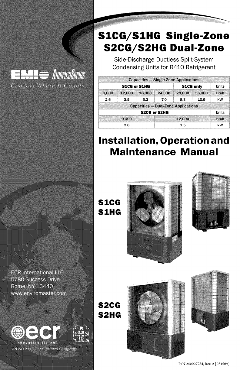
SICG/SIHG Single-Zone
S2CG/S2HG Dual-Zone
Side-Discharge Ductless Split-System
Condensing Units for R410 Refrigerant
2.6 i 3.5 i 5.3 i 7.0 i 8.3 10.5 i kW i
IS2CG orS2HG i Units i
Installation, Operation and
Maintenance Manual
SICG
SIHG
S2CG
S2HG
P/N 240007754, Rev. A [051509]
Contents .............................................................. 2
Verify unit before installing .................................................. 4
Mounting the Unit ........................................................ 6
Electrical Wiring ......................................................... 8
Refrigerant Piping ....................................................... 11
Refrigerant Processing .................................................... 13
Operation Charts ........................................................ 17
Starting the Unit ........................................................ 28
Operation and Maintenance ................................................. 28
Single-zone and Dual-zone Condenser Sequence of Operation .......................... 29
Single-zone and Dual-zone Condenser Sequence of Operation,
Testing Defrost Operation Using Test Pins ........................................ 30
Specification and Dimensions ................................................ 31
Test Unit Performance Data Sheet ............................................. 36
EMI's Product Line ....................................................... 40
Shipping damage MUST be reported
to the carrier IMMEDIATELY.
Examine the exterior. Remove cover
and examine compressor and piping
for signsof damage.
Inspect each component for damage.
Concealed damage must be reported
to the carrier within IS days of the
receipt of the shipment.
The carrier must make proper notation
on the delivery receipt of all damage
identified and complete a carrier inspec-
tion report.
The purchaser must notify ECR Inter-
national's Customer Service Depart-
ment of all damage and is responsible
for filing any necessary claims with the
carrier.
iiiiiiiiiiiiiiiii
iiiiiiiiiiiiiiiii
Retain this manual and warranty for
future reference. Before leaving the prem-
ises, review this manual to be sure the unit
has been installed correctly and run the
unit for one complete cycle to make sure
it functions properly.
To obtain technical service or warranty
assistance during or after the installation
ofthis unit, contact your local representa-
tive. For alocal representative listing, visit
our web site:
For further assistance call:
When calling for assistance, please have
the following information ready:
Model Number
Serial Number
iiiiiiiiiiiiiiii_
Date of installation
The EMI AmericaSeries high efficiency condensing unit is backed by EMI and ECR
International and is tested and rated in accordance with AHRI Standard 210/240-2008
and UL- 1995. Due to ongoing product development, product designs and specifications
may change without notice. Please contact the factory for more information.
Corniest where it count:_ 2 P!N 2400077_4, _ev A {i0!3;_.5001
i i i i i i i i i:i i
iiiiiiiiiiiiiiiiiiCompletely read all instructions
iiiiiiiiiiiiiiiiiiprior to assembling, installing, oper-
iiiiiiiiiiiiiiiiiiating, orrepairingthisproduct.
iiiiiiiiiiiiiiiiiiInspect all parts for damage prior to in-
................................stallation and start-up. The EMI Ameri-
.............................caSeries high efficiency condensing unit
by q
.......................must be installed ONLY ualified
iiiiiiiiiiiiiiiiiiiiiiiiii{i{!i!!!!iinstallationpersonnel.
Tampering with this unit is danger-
ous. Tamperingvoids allwarranties. DO
NOT attempt to modify or change this
unit in any way.
The EMI AmericaSeries must:
• Beconnectedto aproperlygrounded
electrical supply with the proper
voltage as stated on the rating plate.
• Have proper overcurrent protection
(i.e.time-delay fuse/HACRBreaker)
as listed on the rating plate.
Failure to follow these instructions can
result in a fire, explosion, or electrical
shock causingproperty damage,personal
injury; or death.
This manual is intended as an aid to
iiiiiiiiiiiiiiiii
qualified service personnel for proper
installation, operation, and maintenance
of the EMI AmericaSeries high efficiency
condensing unit. Read these instructions
thoroughly and carefully before attempt -
ing installation or operation. Failure to
follow these instructions may result in
_mproper installation, operation, service,
or maintenance, possibly resulting in fire,
electrical shock, property damage, personal
injury, or death.
iiiiiiiiiiiiiiiii
iiiiiiiiiiiiiiiii
iiiiiiiiiiiiiiiii
Read all instructions before using this
unit. Install or locate this unit only in ac-
cordance with these instructions. Use this
iiiiiiiiiiiiiiiii
iiiiiiiiiiiiiiiiiunitonlyforitsintendeduseasdescribed
iiiiiiiiiiiiiiiiiinthismanual.
iiiiiiiiiiiiiiiii
!!!!!!!!!!!!!!!!!Checktheratingplateontheunitbefore
iiiiiiiiiiiiiiiiiinstallationto make certain thevoltage
iiiiiiiiiiiiiiiiishownisthesameastheelectricsupplyto
the unit. The rating plate is located on the
front panel only.
iiiiiiiiiiiiiiiii
iiiiiiiiiiiiiiiii
!!!!!!!!!!!!!!!!!
iiiiiiiiiiiiiiiii
iiiiiiiiiiiiiiiii
This unit must be connected only to a
properly grounded electrical supply. Do
!!!!!!!!!!!!!!!!!not fail to properly ground this unit.
iiiiiiiiiiiiiiiiiWurnofftheelectricalsupplybeforeservic-
iiiiiiiiiiiiiiiii"
iiiiiiiiiiiiiiiiimgtheunit.
iiiiiiiiiiiiiiiiiDonotusetheunitifithasdamagedwir-
iiiiiiiiiiiiiiiiiing, isnotworkingproperly, orhasbeen
iiiiiiiiiiiiiiiiidamaged or dropped.
P/N 240007754, _{ev, A [05ff 5©9 $ Mat:{÷ i_ tBe USA
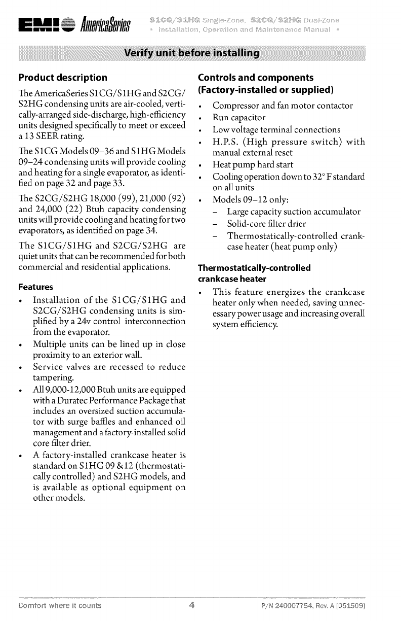
Product description
TheAmericaSeries S1CG/S1HG and S2CG/
S2HG condensing units are air-cooled,verti-
cally-arranged side-discharge,high-efficiency
units designed specifically to meet or exceed
a 13 SEER rating.
The S1CG Models 09-36 and S1HG Models
09-24 condensing units will provide cooling
and heating for a single evaporator, as identi-
fied on page 32 and page 33.
The S2CG/S2HG 18,000 (99), 21,000 (92)
and 24,000 (22) Btuh capacity condensing
units will provide cooling and heating for two
evaporators, as identified on page 34.
The S1CG/S1HG and S2CG/S2HG are
quiet units that can be recommended for both
commercial and residential applications.
Features
• Installation of the S1CG/S1HG and
S2CG/S2HG condensing units is sim-
plified by a 24v control interconnection
from the evaporator.
• Multiple units can be lined up in close
proximity to an exterior wall.
• Service valves are recessed to reduce
tampering.
• All9,000-12,000 Btuh units are equipped
with aDuratec Performance Packagethat
includes an oversized suction accumula-
tor with surge baffles and enhanced oil
management and afactory-installed solid
core filter drier.
• A factory-installed crankcase heater is
standard on S1HG 09 &12 (thermostati-
cally controlled) and S2HG models, and
is available as optional equipment on
other models.
Controls and components
(Factory-installed or supplied)
• Compressor and fanmotor contactor
• Run capacitor
•Lowvoltage terminal connections
• H.P.S. (High pressure switch) with
manual external reset
• Heat pump hard start
• Cooling operation downto 32° Fstandard
on allunits
• Models 09-12 only:
-Large capacity suction accumulator
- Solid-core filter drier
- Thermostatically-controlled crank-
case heater (heat pump only)
Thermostatically-controlled
crankcase heater
This feature energizes the crankcase
heater only when needed, saving unnec-
essarypower usage and increasing overall
system efficiency.
Oomfo_t where it cou_'_ts 4 P!N 240007754, Bey A [05£509I
System options
• Corrosion-resistant coil options (sea
coast and harsh environment usage):
- Copper fin/copper tube condenser
coil
- Coated aluminum fin/copper tube
condenser coil
•LowAmbient controls for cooling opera-
tion down to 0° F (standard equipment
can operate down to 32°F)
- Optional field-installed kit, when
specified, for cooling operation down
to O°F-- kit includes control, louvers .................
iiiiiiiiiiiiiiiii
and wind baffle plus installation
instructions
• Low Ambient controls for operation
down to 0° F (consult factory for avail-
ability)
• Models 09-12 only: iiiiiiiiiiiiiiiii
- 115v (single-zone only-- SICG or
S1HG)
- Field-installed thermostatically-con-
trolled crankcase heater for straight
cool units (S1CG or S2CG)
Installer-supplied items
• Power wiring
• LowVoltwiring (18 awgminimum)
• Secure mounting pad or foundation
• Refrigerant piping (ifnotpurchased from
EMI)
• High Volt Disconnect
• Refrigerant for charging interconnect pip-
ing (see charge table on page 15)
Low Ambient controls are required
when the system is asked to cool at
outdoor temperatures below 32 ° F, this
may cause damage to the compressor
and coil, and may void the warranty. A
field-installed low-ambient kit allows
operation down to 0° E
This is accomplished by cycling the
condenser fan on and off. This will,
in turn, maintain a constant low-side
pressure, providing asteady cooling
effect and keeping the air handler from
frosting-up.
The optional kits include louvers/wind
baffle, crankcase heater, and/or outdoor
fan cycling switch, and installation in-
structions.
_/N 240007754, Rev, A [05ff 509 5 Msd÷ i_ the USA
Before installing, consider:
•Locate the unit as close to the indoor sec-
tion as possible. (see page 11.)
• S 1CG/S2CG -- If the unit is used for low
ambient cooling down to 32°E S1CG/
S2CG require CCH.
• Avoid high traffic areas and prevailing
wind locations.
• Surface must be fiat and level.
• Mount unit above typical snow fall level.
This is particularly important for heat
pump applications (S 1HG/S2HG).
Site preparation
Place the unit on a flat concrete surface
or pad if on the ground. Roof mounting
should use a build up platform to avoid
intake of hot air from the roofi
2. In areas of heavy snowfall, condensers
should be set above the maximum antici-
pated snow line (12" is usually adequate
for most locations).
Unit Mounting Instructions
Model S1CG is shown for example in the
following sequence.
Theside- discharge unit allows forpermanent
mounting through the feet. This is highly
recommended due to the vertical design of
the unit.
1. Figure 1, Page 7:
- Bullet 1 -- Loosen the screws on left
and right sides of the front panel. (Do
not remove these screws.)
- Bullet2 -- Remove the screws on the
front of the panel.
2. Figure 2, Page 7:
Slide front panel forward to clear side
screws and remove.
3. Figure 3, Page 7:
Insert lagbolts through the holes in the
bottom of the unit and tighten to secure.
4. Figure 4, Page 7:
Insert lagbolts through the holes inthe
feet on the back of the unit and tighten
to secure.
5. Replace the front panel, do not tighten
the side screws at this time.
Oomfo_t where it cour_ts @ P!N 240007754, Rev A [05£50%
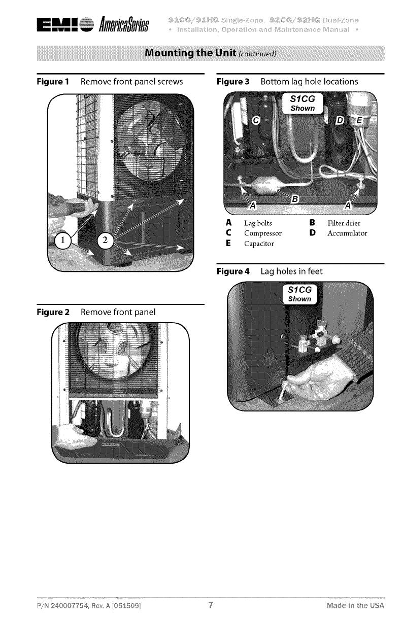
Figure 1 Remove front panel screws Figure3 Bottom lag hole locations
ALag bolts BFilter drier
CCompressor DAccumulator
ECapacitor
Figure4 Lag holes in feet
Figure2 Remove front panel
P/N 240007754, g{ev,A [05S5©9] "d Made i_ the USA
All electricalwiringmustberunaccord-
ing to NEC and local codes.
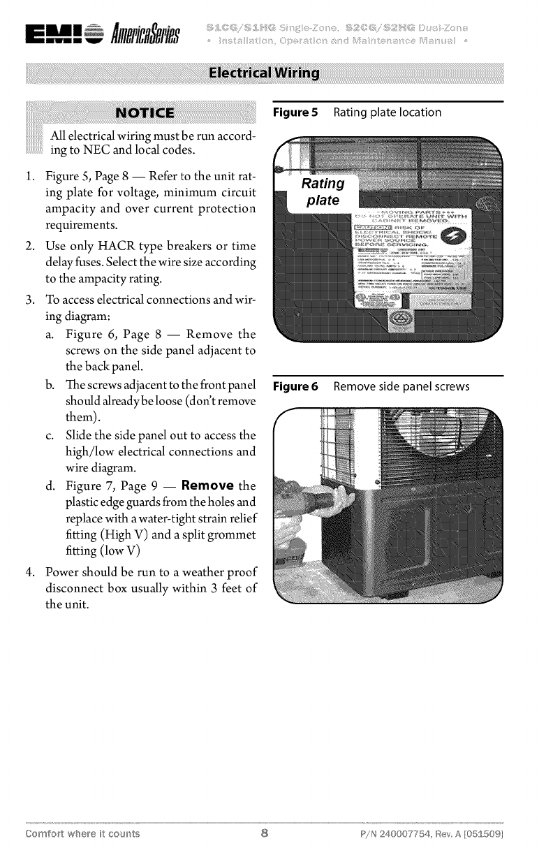
1. Figure S, Page 8 -- Refer to the unit rat-
ing plate for voltage, minimum circuit
ampacity and over current protection
requirements.
2. Use only HACR type breakers or time
delay fuses. Sdect the wire sizeaccording
to the ampacity rating.
3. To access electrical connections and wir-
ing diagram:
a. Figure 6, Page 8 -- Remove the
screws on the side panel adjacent to
the back panel.
b. Thescrews adjacent to the front panel
should alreadybeloose (don't remove
them).
c. Slide the side panel out to access the
high/low electrical connections and
wire diagram.
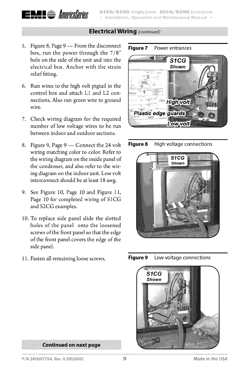
d. Figure 7, Page 9 -- Remove the
plastic edgeguards from the holes and
replace with awater-tight strain relief
fitting (High V) and a split grommet
fitting (low V)
4. Power should be run to a weather proof
disconnect box usually within 3 feet of
the unit.
Figure5 Rating plate location
Figure6 Remove side panel screws
Comfort where it cour_ts 8 P!N 240007754, Bey A [05£509I
5.
6.
Figure 8, Page 9 -- From the disconnect
box, run the power through the 7/8"
hole on the side of the unit and into the
electrical box. Anchor with the strain
relief fitting.
Run wires to the high volt pigtail in the
control box and attach L1 and L2 con-
nections. Also run green wire to ground
wire.
7. Check wiring diagram for the required
number of low voltage wires to be run
between indoor and outdoor sections.
g.
9.
Figure 9, Page 9 -- Connect the 24 volt
wiring matching color to color. Refer to
the wiring diagram on the inside panel of
the condenser, and also refer to the wir-
ing diagram on the indoor unit. Low volt
interconnect should be at least 18 awg.
See Figure 10, Page 10 and Figure 11,
Page 10 for completed wiring of SICG
and S2CG examples.
10. To replace side panel slide the slotted
holes of the panel onto the loosened
screws of the front panel so that the edge
of the front panel covers the edge of the
side panel.
11. Fasten allremaining loose screws.
Figure7 Power entrances
Figure8 High voltage connections
Figureg Lowvoltage connections
P/N 240007754, _tev, A [05S 509 9 Made in the USA
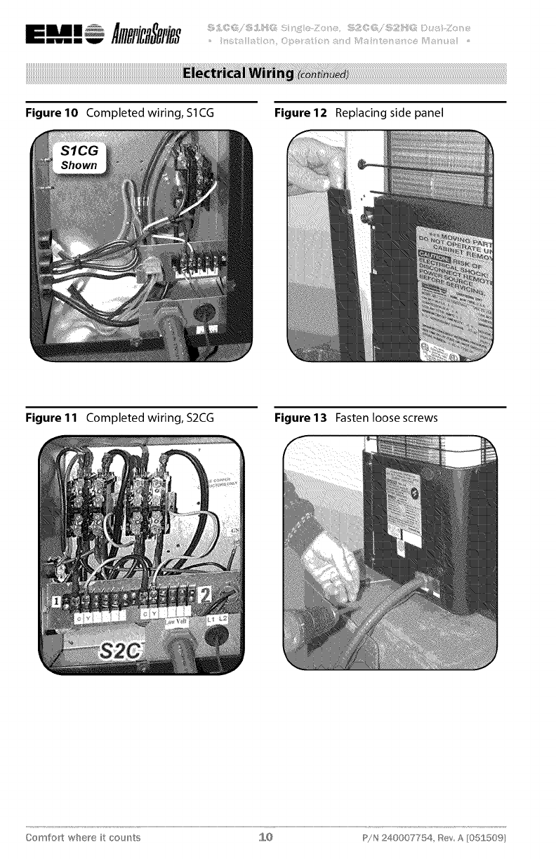
Figure 10 Completed wiring, S1CG Figure 12 Replacing side panel
Figure 11 Completed wiring, S2CG Figure 13 Fasten loose screws
Comfort where it cou_'_ts J,,,O P!N 240007754, _SevA [05£50%
Tubing specifications
The system will support refrigerant runs to
the inside unit as listed in Table 1, Page 11.
The units are furnished with sweat connec-
tions and are equipped with refrigerant valves
and Schrader fittings for charging and taking
pressure readings.
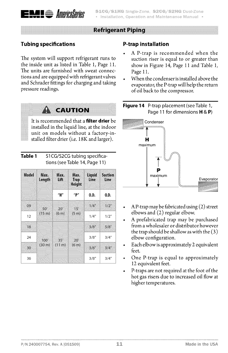
P-trap installation
• A P-trap is recommended when the
suction riser is equal to or greater than
show in Figure 14, Page 11 and Table 1,
Page 11.
• When the condenser isinstalled above the
evaporator,the P-trap willhelp the return
of oil back to the compressor.
It is recommended that a filter drier be
tall di th liq idli th dins e n e u ne, at e in oor
unit on models without a factory-in-
stalled filter drier (i.e. 18K and larger).
Table 1 Sl CG/S2CG tubing specifica-
tions (see Table 14, Page 11 )
12 1/4" 1/2"
24 3/8" 3/4"
36 3/8" 3/4"
Figure 14 P-trap placement (seeTable 1,
Page 11 for dimensions H&P)
Condenser
H
maximum
P
maximum Evaporator
•AP-trap maybe fabricatedusing (2) street
elbows and (2) regular elbow.
• A prefabricated trap may be purchased
from awholesaler or distributor however
the trap shouldbe shallow as with the (3)
elbow configuration.
• Each elbowis approximately 2 equivalent
feet.
• One P-trap is equal to approximately
12 equivalent feet.
• P-traps are not required at the foot of the
hot gas risers due to increased oil flow at
higher temperatures.
P/N 240007754, Rev, A [05J 509] J,,,J,,, Made in the USA
•Avoid piping on wet and rainy days•
!!!!!!!!!!!!!!!!!
• Use only clean, refrigeration-grade
copper tubing.
• Use tubing benders to guard against
kinking.
• Be certain no burrs remain on the
fittings•
• Cap ends of lines until ready for con-
..................
nectiÙns.
• Be certain that plastic end caps remain
......................pl h g th gh all
....................in acew eninsertin rou w
...............openings
• Insulate the suction line•
iiiiiiiiiiiiiiii_i
• Isolate tubing from transmitting vibra-
tion to the building or unit and avoid
contact with sharp edges•
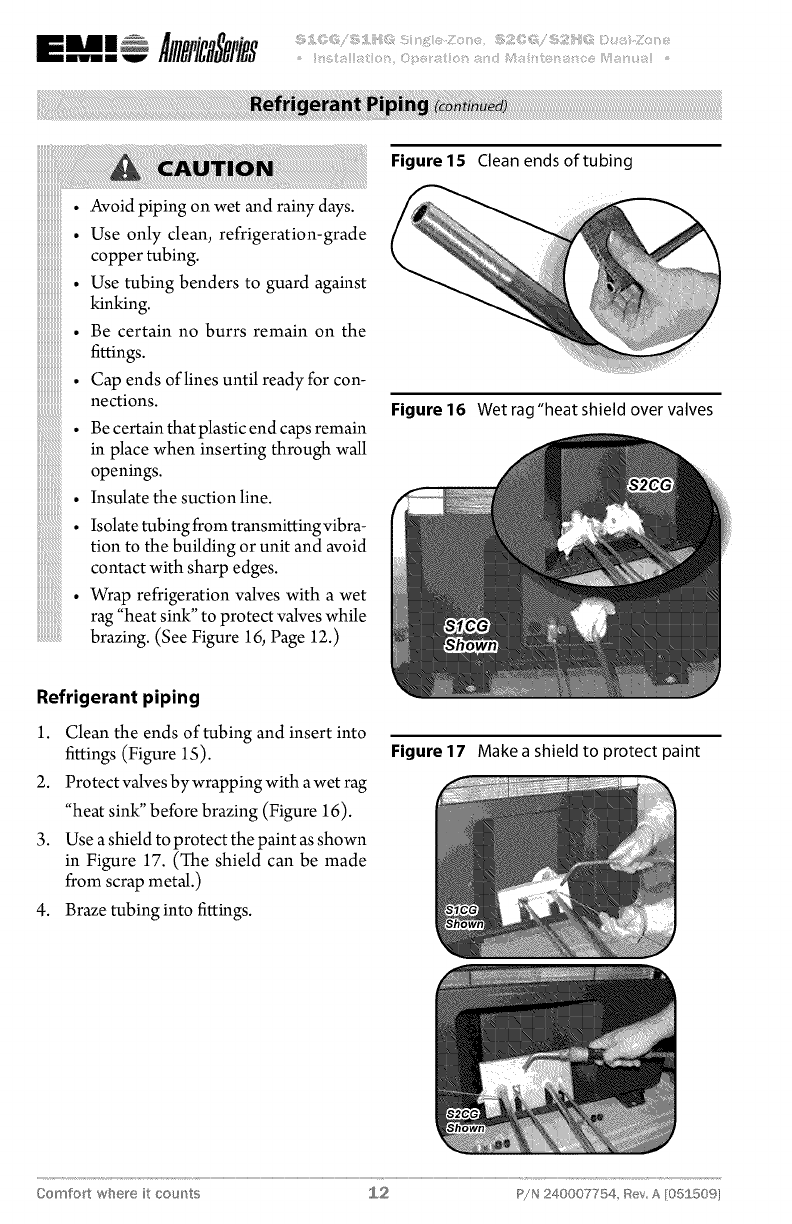
• Wrap refrigeration valves with a wet
rag "heat sink" to protect al hile
v yes w
brazing. (See Figure 16, Page 12.)
Figure 15 Clean ends of tubing
Figure 16 Wet rag "heat shield over valves
Refrigerant piping
1. Clean the ends of tubing and insert into
fittings (Figure 1S).
2. Protect valves by wrapping with a wet rag
"heat sink" before brazing (Figure 16).
3. Use a shield to protect the paint as shown
in Figure 17. (The shield can be made
from scrap metal.)
4. Braze tubing into fittings.
Figure 17 Make a shield to protect paint
Comfort where it cou_'_ts S,,,2 P!N 240007754, _SevA [05£50%
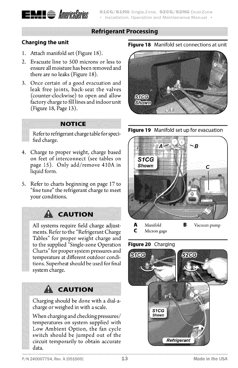
Charging the unit
1. Attach manifold set (Figure 18).
2. Evacuate line to 500 microns or less to
ensure allmoisture hasbeen removed and
there are no leaks (Figure 18).
3. Once certain of a good evacuation and
leak free joints, back-seat the valves
(counter-clockwise) to open and allow
factory charge to filllines and indoor unit
(Figure 18, Page 13).
i ii i i!i!iiiiii!iiiiiiiiiiiiiiiiiiiiiiiiiiiiiiiiiiiiiiiiiiiiiiiiiiiiiiiiiiiiiiiiiiiiiiiiiiiiiiiiiiiiiiiiiiiiiiiiiiiiiiiiiiiiiiiiiii!!!i!!i!!i i! ! !ii !iE!i!i!i!i!i!i!i!i!i!i!i!i!i!i!i!i!i!i!i!i!i!i!!i!i iiiiii ! !!! !i !i !iiiiii i i i i i i iiiiiiiii !! !! ! ! ! ! ! ! ! ! ! ! ! ! ! ! ! ! ! ! ! ! ! ! ! i
Referto refrigerant chargetable for speci-
fied charge.
4. Charge to proper weight, charge based
on feet of interconnect (see tables on
page 15). Only add/remove 410A in
liquid form.
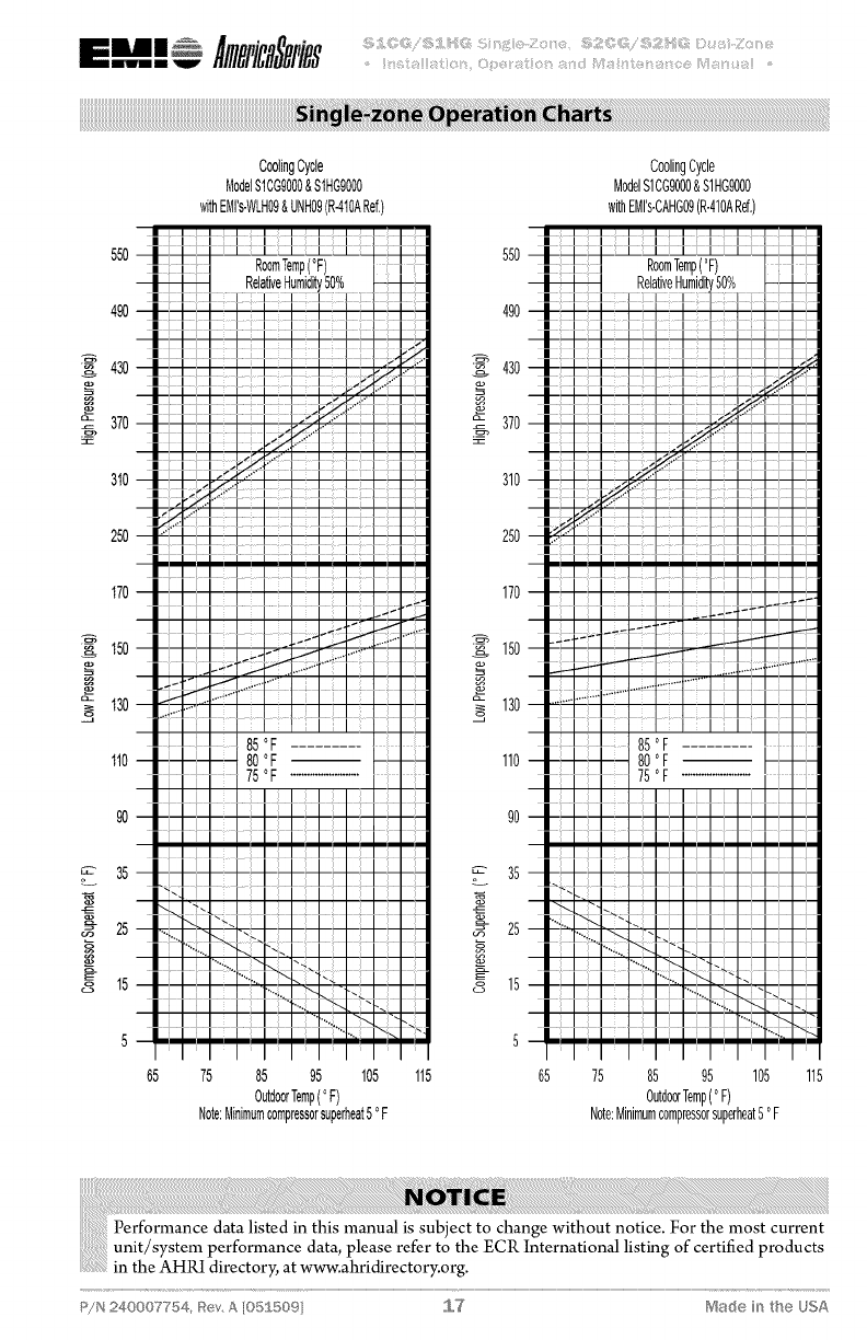
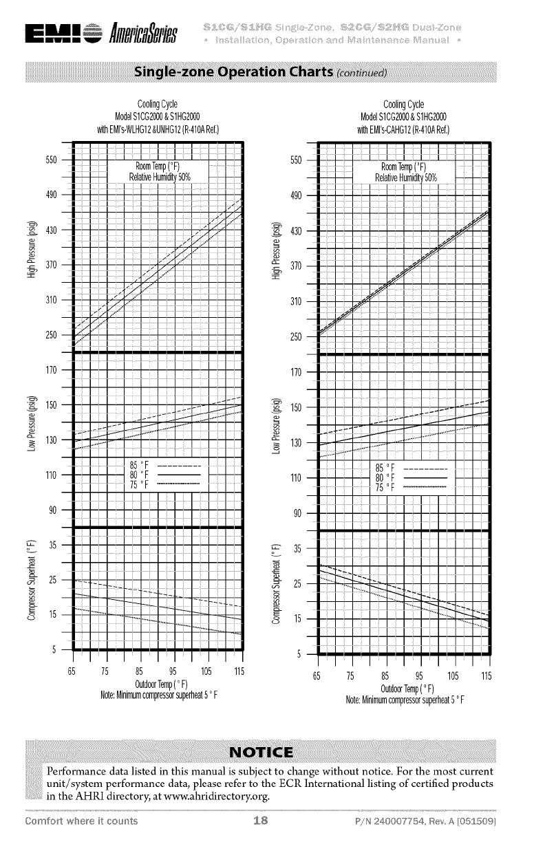
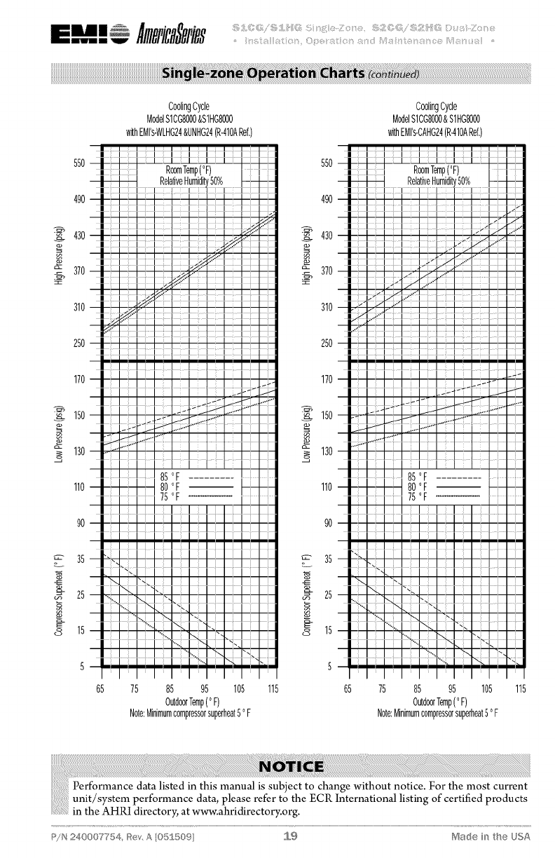
5. Refer to charts beginning on page 17 to
"fine tune" the refrigerant charge to meet
your conditions.
Figure 18 Manifold set connections at unit
Figure 19 Manifold set up for evacuation
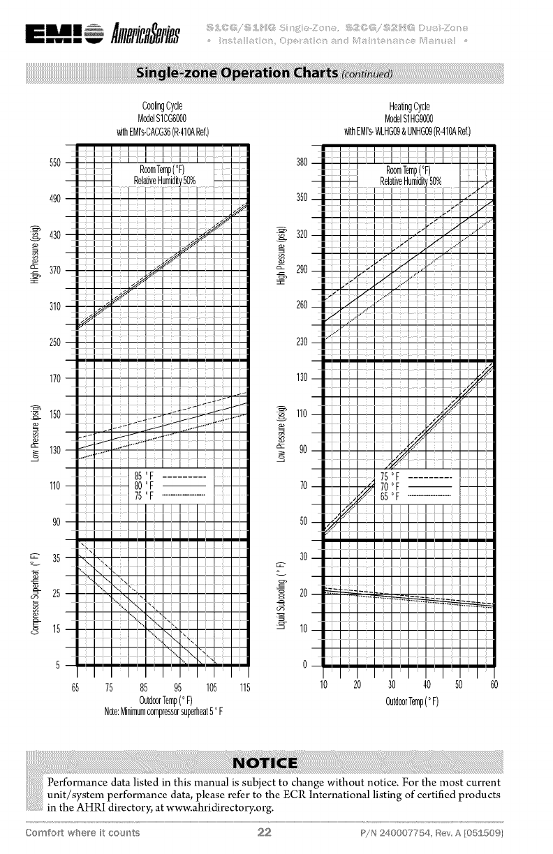
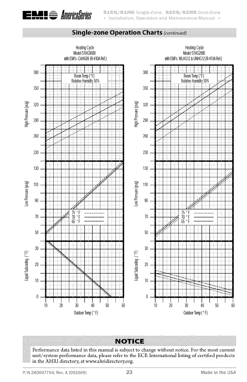
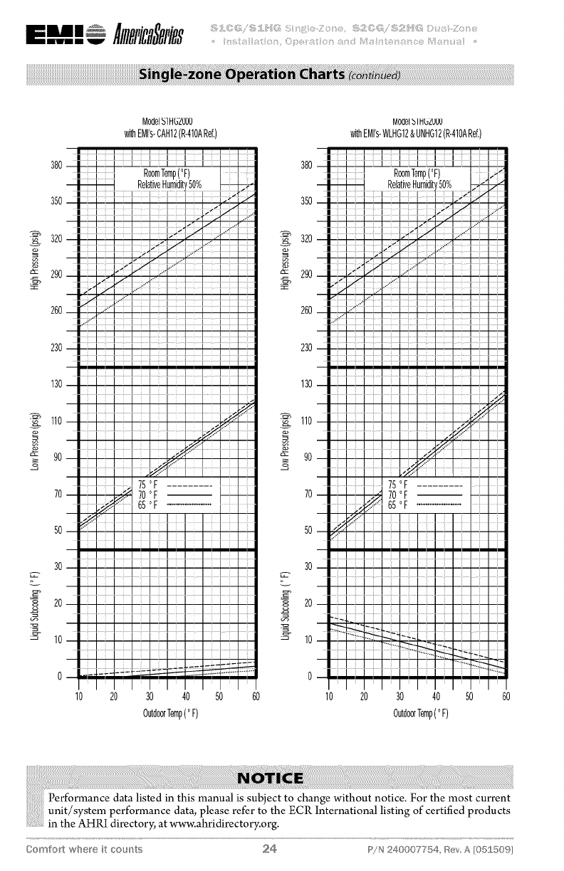
M1 systems require field charge adjust-
ments. Refer to the "Refrigerant Charge
Tables" for proper weight charge and
to the supplied "Single-zone Operation
Charts" for proper system pressures and
temperature at different outdoor condi-
tions. Superheat should be used for final
system charge.
AManifold BVacuum pump
CMicron gage
Figure 20 Charging
Charging should be done with a dial-a-
charge or weighed inwith ascale.
When charging and checking pressures/
temperatures on system supplied with
Low Ambient Option, the fan cycle
switch should be jumped out of the
circuit temporarily to obtain accurate
.................data.
P/N 240007754, _tev, A [05S 5©9 S,,,3 ['VSadein the USA
It is illegal to discharge refrigerant into
iiiiiiiiiiiiii{'ii{i!iiiiiiiiiiiiiiiiiiii theatmosphere. Useproperreclaiming
methods& equipmentwheninstalling
................... g thi
or servicin s unit.
The units are delivered pre-charged with
refrigerant for the condenser coil and the
evaporator. Charging of the fieldinstalled pip-
ing isrequired. Refer to the refrigerant charge
table for the proper amount to be added for
the applications interconnect piping. Unit
service valves are solid brass, for sweat con-
nections.
iiiiiiiiiiiiiiii;
iiiiiiiiiiiiiiii_
iiiiiiiiiiiiiii_
iiiiiiiiiiiiiiiiii
iiiiiiiiiiiiiiiiii
iiiiiiiiiiiiiiiiii
iiiiiiiiiiiiiiiiii
iiiiiiiiiiiiiiiiii
iiiiiiiiiiiiiiiiii
iiiiiiiiiiiiiiiiii
iiiiiiiiiiiiiiiiii
iiiiiiiiiiiiiiiiii
iiiiiiiiiiiiiiiiii
iiiiiiiiiiiiiiiiii
iiiiiiiiiiiiiiiiii
iiiiiiiiiiiiiiiiii
Pressuretest all field installed piping
with nitrogen. Using a suitable vacuum
pump, evacuate the tubing and indoor
unit to SO0microns or less, with service
valves remaining front seated (closed).
Before releasing the refrigerant from the
condenser, be sure the manifold gauge
set is closed so as not to lose vacuum
when shutting down the pump.
Release refrigerant from the condensing
unit by back seating the service valve. M-
len wrenches are used to open the valve.
Replace valve caps. DO NOT back seat
the valves past the snap flanges that hold
the valve core in place.
Comfort where it counts S,,,4 P!N 240007754, _SevA [05£50%
iiiiiiiiiiiiiiiii:1.
iiii!}iiiiiiiiiiiiiiiiiiiiiiiiiiiiiiiiiiiiiiiiii
!!!!!!!!!!,s_s_
!!!!!!!!!!!,s_s_
iiiiiiiiiiiiiiiiiiiiiiiiiiiiiii!i!!!!i2
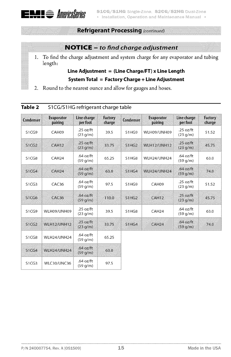
To find the charge adjustment and system charge for any evaporator and tubing
length:
Line Adjustment =(Line Charge/FT} x Line Length
System Total =Factory Charge + Line Adjustment
Round to the nearest ounce and allow for gauges and hoses.
Table 2S1CG/S1HG refrigerant charge table
S1CG9 CAH09 .25 oz/ft
(23 g/m) 39.5 .25 oz/ft
$1HG9 WLH09/UNH09 (23 g/m) 51.52
S1CG8 CAH24 .64 oz/ft
(59 g/m) 65.25 .64 oz/ft
$1HG8 WLH24/UNH24 (59 g/m) 63.0
$1CG3 CAC36 .64 oz/ft
(59 g/m) 97.5 S1HG9 CAH09 .25 oz/ft
(23 g/m) 51.52
.25 oz/ft
S1CG9 WLH09/UNH09 (23 g/m) 39.5 S1HG8 CAH24 .64 oz/ft
(59 g/m) 63.0
.64 oz/ft
S1CG8 WLH24/UNH24 (59 g/m) 65.25
.64 oz/ft
$1CG3 WLC30/UNC36 (59 g/m) 97.5
P/N 240007754, _{ev, A [05] 50% S,,,5 Ma(_e in the USA
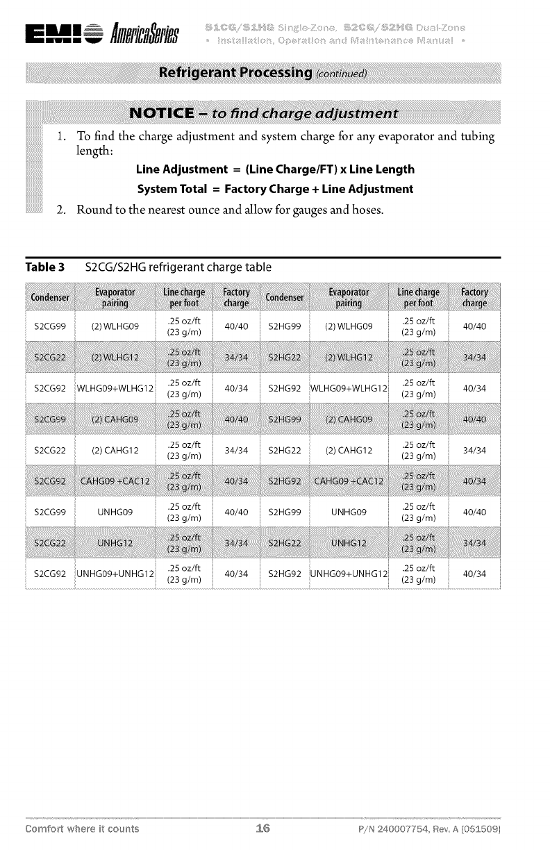
iiiiiiiiiiiiiiiiii1. To find the charge adjustment and system charge for any evaporator and tubing
length
............................. Line Adjustment = (Line Charge/FT) x Line Length
........................ System Total = Factory Charge + Line Adjustment
..................2. Round to the nearest ounce and allow for gauges and hoses.
Table 3 S2CG/S2HG refrigerant charge table
$2CG99 (2)WLHG09
.25 oz/ft
(23 g/m) 40/40 $2HG99 (2) WLHG09 .25 oz/ft
(23 g/m) 40/40
.25 oz/ft
$2CG92 WLHG09+WLHG12 (23 g/m)
.25 oz/ft
40/34 $2HG92 WLHG09+WLHG12 (23 g/m) 40/34
$2CG22 (2) CAHG12 .25 oz/ft
(23 g/m) 34/34 $2HG22 (2) CAHG 12 .25 oz/ft
(23 g/m) 34/34
$2CG99 UNHG09 .25 oz/ft
(23 g/m) 40/40 $2HG99 UNHG09 .25 oz/ft
(23 g/m) 40/40
25 oz/ft .25 oz/ft
$2CG92 UNHG09+UNHG12 " , 40/34 $2HG92 UNHG09+UNHG12 ,, 40/34
_: (23 g/m) (23 g/m)
Comfort where it counts S,,,6 P!N 240007754, _ev A [05£50%
55O
490
_. 430
o_ 370
310
250
170
150
o_
o_ 130
110
90
m 35
25
8 15
CootingCycte
ModelS1CGgO00&StHG9000
withEMI's-WLH09&UNH09(R-410ARet)
550
490
430
370
310
250
170
150
_ 130
110
90
35
_- 25
15
CoolingCycle
ModelS1CG9000&S1HG9000
withEMI's-CAHG09(R-410ARef,)
65 75 85 95 105 115 65 75 85 95 105 115
OutdoorTemp(°F) OutdoorTernp(°F)
Note:Minimumcompressorsuperheat5°F Note:Minimumcompressorsuperheat5° F
P/N 240007754, _ev, A [05S509 _,,,7 ['_$a_:_÷in the USA
mul Amica vies
55O
490
430
9_
_=
_, 370
310
25O
170
_. 150
130
110
90
o_ 35
N- 25
_ 15
CoolingCycle CoolingCycle
ModelS1CG2000$S1HG2000 ModelS1CG2000&S1HG2000
withEMI's-WLHG12&UNHG12(R-410AReh) withEMI's-CAHG12(R-410ARef,)
550
490
_430
370
310
25O
170
_150
130
110
35
_4 25
_ 15
65 75 85 95 105 115 65 75 85 95 105 115
OutdoorTemp(°F) OutdoorTemp(°F)
Note:Minimumcompressorsuperheat5°F Note:Minimumcompressorsuperheat5°F
Comfort where it cou_'_ts S,,,8 P!N 240007754, Rev A [05£50%
550
49O
430
_- 370
310
250
170
150
A- 130
o
110
90
35
2g_ 25
8 15
CoolingCycle
ModelS1CG8000&S1HGS000
withEMI's-WLHG24&UNHG24(R-410ARef,)
550
490
_ 430
_- 370
310
250
170
_150
130
110
90
35
_- 25
8 15
CoolingCycle
ModelS1CG8000&S1HG8000
withEMI's-CAHG24(R-410ARef,)
5
65 75 85 95 105 115 65 75 85 95 105 115
OutdoorTemp(°F) OutdoorTemp(°F)
Note:Minimumcompressorsuperheat5°F Note:Minimumcompressorsuperheat5°F
P/N 240007754, _ev, A [O5S509 _,,,9 r'_$a_:_÷in the USA
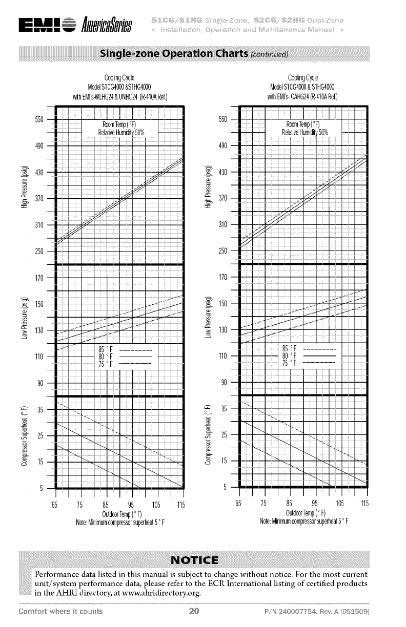
CoolingCycle
ModelS1CG4000&S1HG4000
withEMrs-WLHG24&UNHG24(R-410ARef,)
550 550
RoomTemp(°F)
RelativeHumidit'
490 490
-_ 43o -_ 43o
_- 370 _- 370
310 310
CoolingCycle
ModelS1CG4000&S1HG4000
withEMrs-CAHG24(R-410ARef,)
250 250
170 170
I_ 150 I_ 150
_ 13o_-_@ _ 13o
110 110
90 _ _ 90
35 _ 35
_- 25 _ _ 25
_-15 _ 15
75 85 95 105 115 65 75 85 95 105
OutdoorTemp(°F) OutdoorTemp(°F)
Note:Minimumcompressorsuperheat50F Note:Minimumcompressorsuperheat5°F
115
Comfort where it oou['}ts 20 P!N 240007754, Rev A Z05£50%
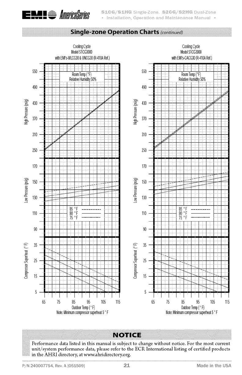
55O
490
430
_- 370
310
250
170
150
_ 130
110
90
35
_- 25
8 15
CoolingCycle CoolingCycle
ModelSLOG3000 ModelS1CG3000
withEMI's-WLCG30&UNCG30(R-410ARef.) withEMI's-CACG30(R-410ARef.)
550
490
_ 430
_- 370
310
250
170
_. 150
o_ 130
110
90
£ 25
75 85 95 105 115 65 75 85 95 105
OutdoorTemp(oF) OutdoorTemp(oF)
Note:Minimumcompressorsuperheat50F Note:Minimumcompressorsuperheat50F
115
P/N 240007754, _ev, A lOSS509 2]... ['_$ac:_÷in the USA
55O
490
430
_- 370
310
250
170
150
_ 130
q
110
90
_" 35
_- 25
N-
8 15
CoolingCycle
ModelS1CG6000
withEMI's-CACG36(R-410ARef,)
RoomTemp(°F)
RelativeHumidb
ilili
II I
€
380
350
_ 320
a- 290
260
230
130
_ 110
_ 9O
70
50
30
20
10
HeatingCycle
ModelS1HGgO00
withEMI's-WLHG09&UNHG09(R-410ARef,)
65 75 85 95 105 115 10 20 30 40 50
OutdoorTemp(°F) OutdoorTemp(°F)
Note:Minimumcompressorsuperheat5oF
60
Comfort where it cou_'_ts 22 P!N 240007754, _SevA [05£50%
380
350
_ 320
";- 290
260
230
130
11o
_- 90
o
30
8 20
} lO
HeatingCycle
ModelS1HGgO00
withEMI's-CAHG09(R-410ARef,)
10 20 30 40 50 60
OutdoorTemp(°F)
38O
350
_ 320
_- 290
260
230
130
_ 110
_- 90
70
50
30
20
I0
HeatingCycle
ModelS1HG2000
withEMI's-WLHG12&UNHG12(R-410ARef,)
30 40 50
OutdoorTemp(oF)
P/N 240007754, Rev, A [05S509 23 Made in the USA
380
350
_ 320
_- 290
260
230
130
_ 110
_- 90
50
30
20
_- 10
Models1HGZOUO
withEMI's-CAH12(R-410ARef,)
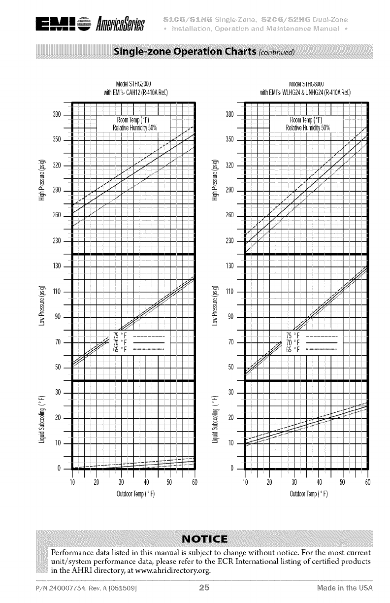
38O
350
_ 320
_- 290
260
230
130
11o
_- 90
30
20
I0
MOdelblIflbZUUU
withEMrs-WLHG12& UNHG12(R-410ARef,)
20 30 40 50 60 10 20 30 40 50 60
OutdoorTemp(oF) OutdoorTemp(oF)
Comfort where it oou['}ts 24 P!N 240007754, Rev A [05£50%
380
350
_ 320
";- 290
260
230
130
11o
_- 90
o
30
8 20
} lO
Model5]HGZOO0
withEMI's-CAH12(R-410ARef,)
10 20 30 40 50 60
OutdoorTemp(°F)
38O
350
_ 320
_- 290
260
230
130
_ 110
_- 90
70
50
30
20
I0
MOdelbllflb_ddd
withEMrs-WLHG24&UNHG24(R-410ARef,)
30 40 50
OutdoorTemp(oF)
P/N 240007754, Rev, A [05S509 25 Made in the USA

380
350
_ 320
_- 290
260
230
130
_ 110
_- 90
50
30
20
_- 10
ModelSlHGSOO0
withEMrs-CAH24(R-410ARef,)
38O
350
_ 320
_- 290
260
230
130
11o
_- 90
30
20
I0
MOdelb llflbqUUg
withEMrs-WLHG24&UNHG24(R-410ARef,)
20 30 40 50 60 10 20 30 40 50 60
OutdoorTemp(oF) OutdoorTemp(oF)
Comfort where it oou['_ts 26 P!N 240007754, Rev A [05£50%
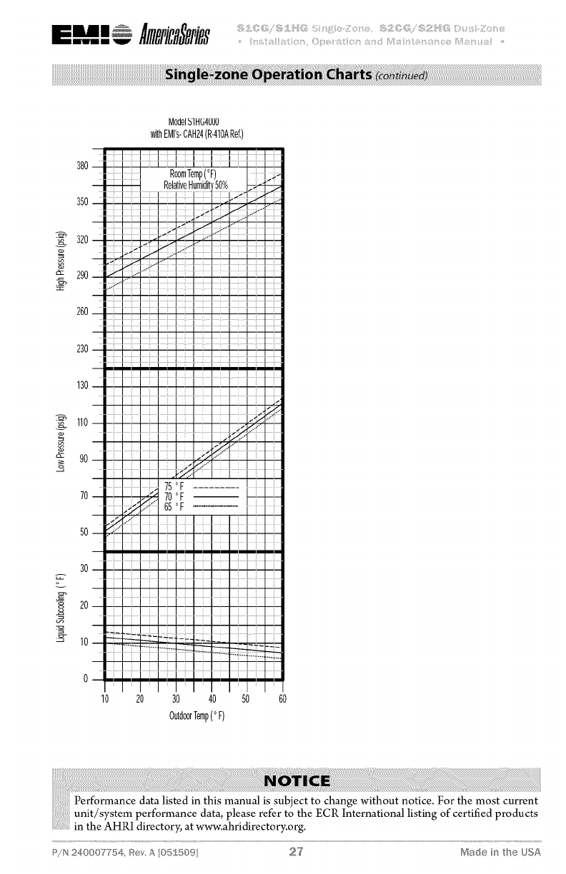
380
Model5]HG4OUO
withEMI's-CAH24(R-410ARef,)
350
_ 320
";- 290
260
230
130
110
A- 90
o
30
8 20
0
10 20 30 40 50 60
OutdoorTemp(°F)
P/N 240007754, Rev, A [05S509 27 Ma(_ein the USA
9,000- 12,000 Btuh units
In low ambient cooling, ifa crankcase heater is
installed, power the system 24 hours before
attempting to start the unit in cool weather
(below 60 ° F).
Test unit data sheet
After doing a final system check using the
Operation Charts (supplied on previous
pages).
Record results on Test Unit Data Sheet on
page 36.
Before leaving
Remove gauge set. Mount all access panels
and make sure they areproperly secured.
Make final visual inspection and repair any
deficiencies.
A hard start kit may be required for units
in low voltage applications.
The S 1CG/S 1HG and S2CG/S2HG outdoor
sections are the compressor bearing units of
the system. It operates at the command of the
indoor section or room thermostat. Therefore,
the system operation will be described in the
manual pertaining to the indoor section.
EMI units are designed and constructed
for reliability and long life with minimal
maintenance. You can assure peak operating
efficiency by regularly inspecting for free air
passage into and through the coil. If debris
collects on the air coil, it should be cleaned
by "back-flushing" with a spray of water or
vacuuming. TURN OFF POWER SUPPLY
FIRST. Outdoor units may be cleaned or
waxed if desired. Use a non-abrasive car wax
(on metal surfaces only).
This unit is equipped with a permanently
lubricated motor. Mthough oiling is not nec-
essary; adding a few drops through the oiling
ports twice yearly will extend the life of the
motor. Do not over oil.
Panels should remain on the unit at all times.
Service should be performed by a qualified
service agency only.
Specific changes
All EMI products are subject to ongoing
development programs so design and speci-
fications may change without notice. Please
consult the factory for more information.
Comfort where it cour_ts 28 P!N 240007754, _SevA [05£50%
EMI AmericaSeries condensers are designed
to operate with EMI AmericaSeries evapora-
tors. Both the condenser (outdoor unit) and
evaporator (indoor unit) have a high volt ser-
vice connection. Each is to be independently
connected to the electrical service panel. (See
the unit name plate for the correct breaker
type and size). The outdoor and indoor units
are also connected to each other through a low
volt interconnect wiring. A 24v transformer
located in the indoor unit provides the low volt
power source.
Straight cool condensers are designed to oper-
ate as a single stage cooling unit. Heat pump
condensers are designed to operate as a single
stage cooling two stage heating unit. For proper
operation the unit must be matchedwith an ap-
propriate EMI indoor unit with unit mounted
controls and/or wall mounted thermostat. For
two-stage heating operation the indoor unit
must be equipped with an electric strip heater.
.............................For remote wall mounted thermostat
.........................operation be sure to select EMI p/n
iiiiiiiiiiiiiiiiiiiiiiiii!i!i!!i240004180orasuitable24v, twostage
heating, heat pump thermostat.
Condenser operation
The transformer located in the indoor unit
provides 24v, low-volt control power to the
condenser (outdoor unit). This canbemeasured
across low-volt terminals "R" and "C".
Heat pump condensers utilize areversing valve
to provide reverse cycle operation. Therefore
the outdoor unit will act as either a condenser
or an evaporator there-by providing comfort
cooling or heating to the indoor space. The
reversing valve is energized in cooling. Should
the valve fail to actuate, the system will default
to the heating mode of operation.
Cooling operation, single- and dual-zone
Cooling operation requires that the control
(either unit mount or remote wall mount ther-
mostat) make a connection between low-volt
terminals "R" and "Y" along with "R" and "O"
(heat pumps only). When the indoor control
is placed in cooling mode, with the set point
temperature below the room temperature, the
reversing valvewill energize (R & O heat pumps
only) along with the compressor and outdoor
fan (R & Y). When the indoor control is satis-
fied and the room temperature falls below the
set temperature, the compressor and fan will
de-energize. The anti-short cycle timer (ASCT)
will prevent the compressor from re-starting for
three minutes.
Heating operation
Heating operation requires that the control
(either unit mount or remote wall mount, heat
pump thermostat) make a connection between
low-Volt terminals "R" and "Y" only. When the
indoor control is placed in heating mode, with
the set point temperature above room tem-
perature, the compressor and outdoor fan (R
& Y) will energize. When the indoor control is
satisfied and the room temperature rises above
the set temperature, the compressor and fanwill
de-energize. The anti-short cycle timer (ASCT)
will prevent the compressor from re-starting for
three minutes.
Defrost controls with short cycle
protection (heat pumps only}
The unit is equipped with a logic control circuit
designed to keep system operating at peek ef-
ficiency. The 24v circuit provides control to
the indoor and outdoor systems including a
three minute, anti-short cycle timer (ASCT)
compressor protection.
The defrost control circuit is designed to keep
the condenser coil free from frost and ice during
heatingmode. This is accomplished through the
precise switching sequence of the outdoor fan,
reversing valve and indoor auxiliary heater.
Defrost initiation
The defrost-sensor is located on either the end
plate or the return bend of the condenser coil.
A defrost cycle will initiate after the sensor
doses (approx. 30° F) and remains closed for
the length of time selected on the control board
(either 30, 60 or 90 minutes)*.
At the start of the defrost cycle, the revers-
ing valve will change from heating to cooling
mode. The condenser fan will also switch off
there-by allowing pressure and temperature
P/N 240007754, _{ev, A [05ff 5©9 29 rVSat_e in the USA
BI m W _ )iiii!i5i);_!!_))))_!!_)i:iJ<);)i'ii= @ )!;i¸iii!¸¸¸))_;;!ii)i:iJ<);i_ii_;i;iii¸i:);!)_[i;_!i;)))i¸ii)i!i!_)?ii_;!ii)i'ii0 _!i!_¸!15/!_!!iii?iiLi;!!!_)) _
to rise within the condenser coil to melt off
any ice build-up. At the same time the unit will
switch on the indoor electric strip heater to
temper the cold air being discharged from the
evaporator unit. This will continue until either
the defrost-sensor opens (approx. 60 ° F) or a
10-minute maximum cycle time has elapsed.
Defrost times will vary depending on outdoor
temperature and moisture conditions. When
the defrost cycle is complete the unit will return
to normal heating operation.
*Factory settings 9-24k Btu = 90 minutes
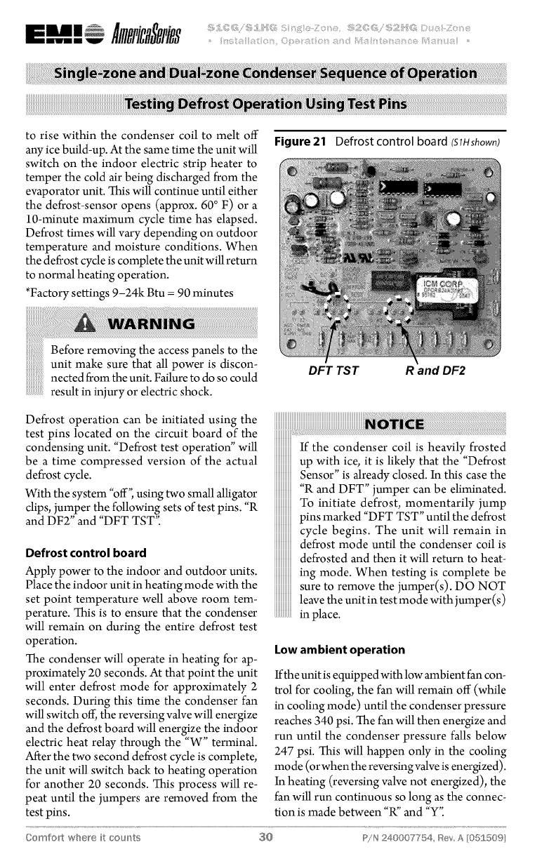
Figure 21 Defrost control board (SlHshown)
Beforeremovingtheaccesspanelstothe
unit make sure that all power is discon-
nectedfromtheunit. Failureto do so could
)))))))))))))),=
))))))))))))))),
result in injury or electric shock.
DFT TST R and DF2
Defrost operation can be initiated using the
test pins located on the circuit board of the
condensing unit. "Defrost test operation" will
be a time compressed version of the actual
defrost cycle.
With the system "off", using two small alligator
clips, jumper the following sets of test pins. "R
and DF2" and "DFT TST".
Defrost control board
Apply power to the indoor and outdoor units.
Place the indoor unit in heating mode with the
set point temperature well above room tem-
perature. This is to ensure that the condenser
will remain on during the entire defrost test
operation.
The condenser will operate in heating for ap-
proximately 20 seconds. At that point the unit
will enter defrost mode for approximately 2
seconds. During this time the condenser fan
will switch off, the reversing valve will energize
and the defrost board will energize the indoor
electric heat relay through the "W" terminal.
After the two second defrost cycle is complete,
the unit will switch back to heating operation
for another 20 seconds. This process will re-
peat until the jumpers are removed from the
test pins.
If the condenser coil is heavily frosted
up with ice, it is likely that the "Defrost
Sensor" is already closed. In this case the
"R and DFT" jumper can be eliminated.
To initiate defrost, momentarily jump
pins marked "DFT TST" until the defrost
cycle begins. The unit will remain in
defrost mode until the condenser coil is
defrosted and then it will return to heat-
ing mode. When testing is complete be
sure to remove the jumper(s). DO NOT
leave the unit in test mode with jumper (s)
Low ambient operation
Ifthe unit is equipped with low ambient fan con-
trol for cooling, the fan will remain off (while
in cooling mode) until the condenser pressure
reaches 340 psi. The fan will then energize and
run until the condenser pressure falls below
247 psi. This will happen only in the cooling
mo de (or when the reversing valve is energized).
In heating (reversing valve not energized), the
fan will run continuous so long as the connec-
tion is made between "R" and "Y".
Comfort where it cour_ts 30 P!N 240007754, Bey A [05150%
iiiiiiiiiii i!ii!i!!i!iiiiiiiiiiiii.... i iii iii! i !il
Performance data listed in this manualis subject to change without notice. For the most cur-
rent unit/system performance data, please refer to the ECR International listing of certified
products in the AHPd directory; at www.ahridirectory.org.
Due to ongoing product development, designs, specifications, and performance are
subject to change without notice. Please consult the factory for further information.
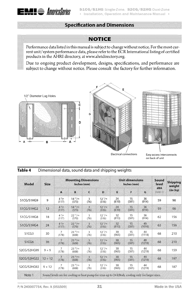
1/2" Diameter Lag Holes
_iii};_iiN#iii/iiiiiii[iiii!!iiiiiiii_:iiiiiiiiii_iii_iii;;iiiiiiliii#_
iii !:_%iii_ii_;iiiiii!ii_;i;ii!_iiiii!!iii,;,},iiiiiii_iiiii/ii!i!i!iii_ii!I il
_ A-_ ...................................B........................................A
E
Electrical connections Easy access interconnects
on back of unit
Table 4 Dimensional data, sound data and shipping weights
S1CG/S1 HG9 4 sis 14 u/_o
(117) (373) 3
(76) 12 z/_ 24 15
(316) (610) (381) 36
(914) 59 98
S1CG/S1HG8 18 4 _/_, 22 _/_6
(117) (570) 3
(76) 12 7/_6 32
(316) (813)
15 36
(381) (914) 62 156
S1CG3 3O 7 23 _s/_,
(178) (608)
3
(76)
127/_o 38
(316) (965)
15 44
(381) (1118) 68 210
7 23 _s/_,
S2CG/S2HG99 9 + 9 (178) (608) 3
(76) 12 7/_6 38
(316) (965)
15 44
(381) (1219) 68 159
7 23 _s/_6
S2CG/S2HG92 9+12 (178) (608)
3
(76)
12 7/_6 38
(316) (965)
15 44
(381) (1219) 68 187
P/N 240007754, Rev, A [O5_ 509 3[_ii, ['?_ade in the USA
mun Amic@ies
BIIII W .... iiiiS_i_43i!ii!!_:!_ii%_qi_il}ii_iiii!4_!i_ii!!!i:Lii¸ _!i!i_ii_sii:_ii_iii_!i!iiiiiiiii3i3q!i_i!_iii3_i:_ili!_i!Y/81i(iiL!_ii!i_il....
Table 5 $I CG electrical specifications
SICG2A
SICG2D
SICG4D
SICG6D
115/60/I
208/230/60/I
208/230/60/I
208/230/60/I
1.4
0.8
0.8
1.8
0.125
0.125
0.125
0.330
9.9
5.2
8.0
12.7
53
27
43
74
11.3
6.0
8.8
14.5
104
197
197
197
13.8
7.3
10.8
17.7
20
15
15
30
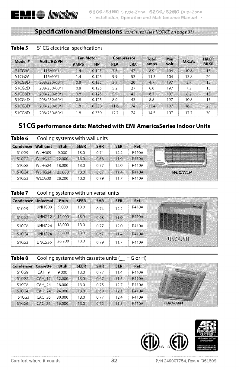
S1 CGperformance data: Matched with EMI AmericaSeries Indoor Units
Table 6
$1CG9
S1CG8
S1CG3
Table 7
$1CG9
S1CG8
S1CG3
Table 8
S1CG9
S1CG8
S1CG3
Cooling systems with wall units
WLHG09 13.0 0.74
WLHG24 18,000 13.0 0.77
WLCG30 28,200 13.0 0.79
Cooling systems with universal units
UNHG09 13.0 0.74 12.2
12.2 R410A
12.0 R410A
11.7 R410A
R410A
UNHG24 18,000 13.0 0.77 12.0 R410A
UNCG36 28,200 13.0 0.79 11.7 R410A
Cooling systems with cassette units (__ = G or H)
9,000 13.0 0.77 11.4 R410A
CAH24 13.0 0.75 12.7 R410A
13.0 0.77 12.4 R410A
(Do_l"_l_t where it counts $2 P!N 2400077_4, Rev A I0!S:£50%
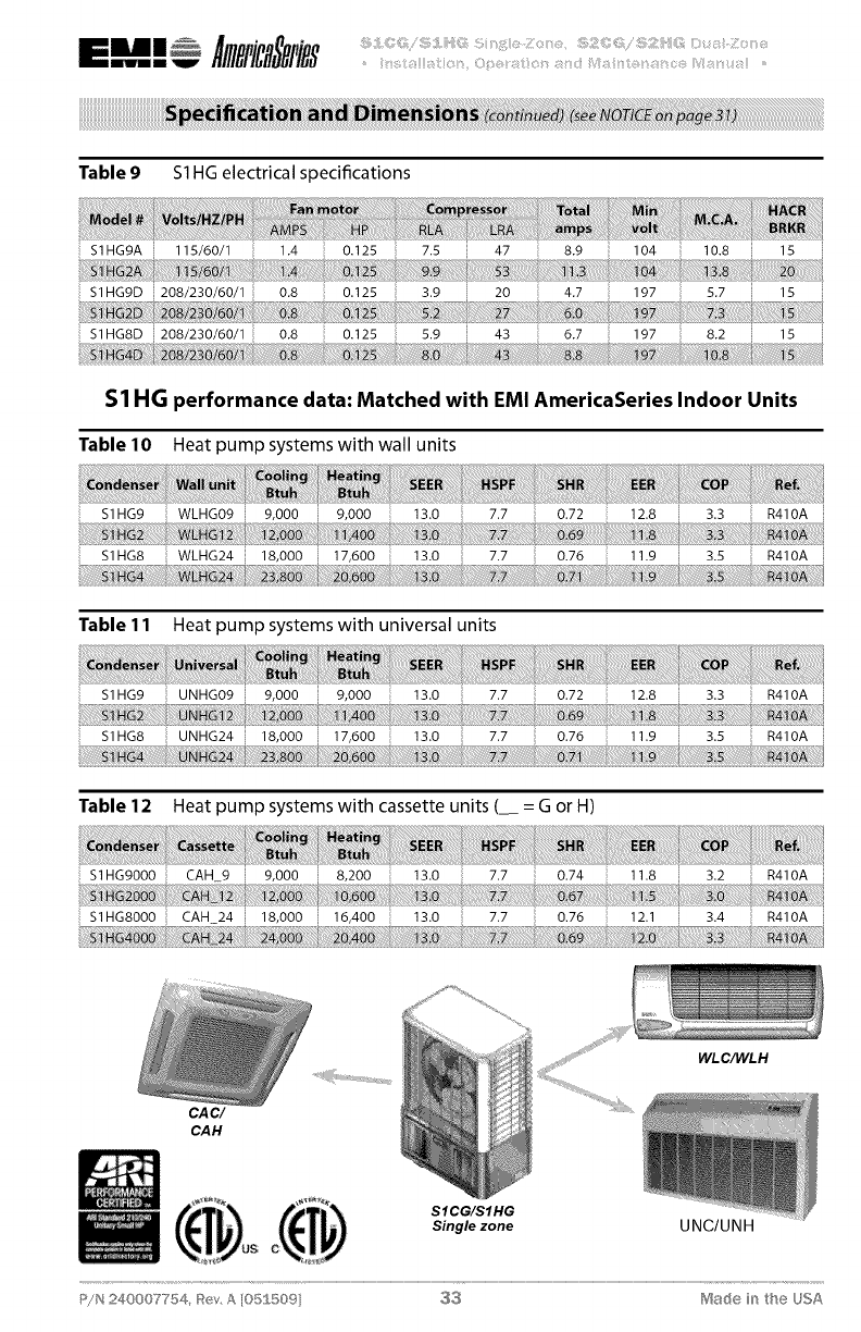
Table 9 SI HG electrical specifications
SIHG9A 115/60/I 1.4 0.125 7.5 47 8.9 104 10.8 15
S1HG9D 208/230/60/1 0.8 0.125 3.9 20 4.7 197 5.7 15
1
S1HG8D 208/230/60/1 0.8 0.125 5.9 43 6.7 197 8.2 15
$1 HG performance data: Matched with EMI AmericaSeries Indoor Units
Table 10 Heat pump systems with wall units
S1HG9 WLHG09 %000 %000 13.0 7.7 0.72 12.8 3.3 R410A
Table 11 Heat pump systems with universal units
S1HG9 UNHG09 13.0 7.7 0.72
Table 12 Heat pump systems with cassette units (_ = G or H)
S1HGg000 CAH 9 9,000 8,200
S1HGS000 CAH 24 18,000 16,400
13.0
13.0
7.7
7.7
0.74
0.76
11.8
12.1
3.2
3.4
R410A
R410A
CAC/
CAH
WL C/WL H
SICG/SIHG
Single zone U NCI U NH
P/N 240007754, Rev, A [05S 5©9] 33 Made in the USA
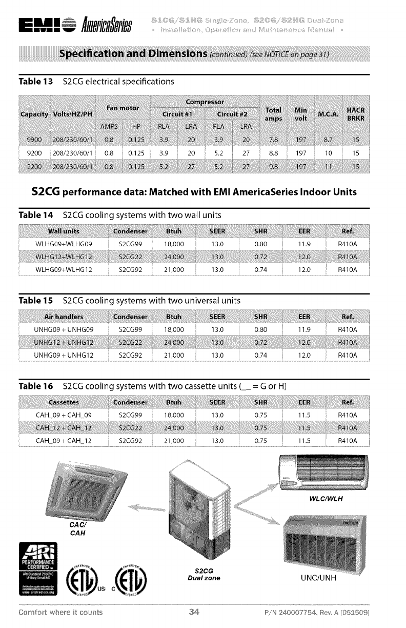
Table 13 S2CG electrical specifications
9200 i208/230/60/1 0.8 0.125 3.9 20 5.2 27 8.8 197 10 15
S2CG performance data: Matched with EMI AmericaSeries Indoor Units
Table 14 S2CG cooling systems with two wall units
WLHG09+WLHG09 $2CG99 18,000 13.0 0.80 11.9 R410A
WLHG09+WLHG 12 $2CG92 21,000 13.0 0.74 12.0 R410A
Table lS S2CGcooling systems with two universal units
UNHG09 + UNHG09 $2CG99 18,000 13.0 0.80 11.9 R410A
UNHG09 + UNHGI 2 $2CG92 21,000 13.0 0.74 12.0 R410A
Table 16 S2CG cooling systems with two cassette units (__ = G or H)
CAH_09 + CAH09 $2CG99 18,000 13.0 0.75 11.5 R410A
......................CAH 09+CAIq ! _ .................. $2CG92 ............................ ...............13.0 ........................................0:75 .....................iI................]1:5 .............................E_4]0_ .............
CAC/
CAH
mmumm A SPiB8 ::: :
_mW ....iiiiS_i_ii3i!ii!!_:!_ii%;qi_il}ii_iiii!:q!_;i_;i!!!i:i:i¸_;i!i;ii_sSii_iii_;i!iiiiiiii;i3i3q!i_i!_iii3_i;_ilisi!YISi/i_L!_ii!i;il....
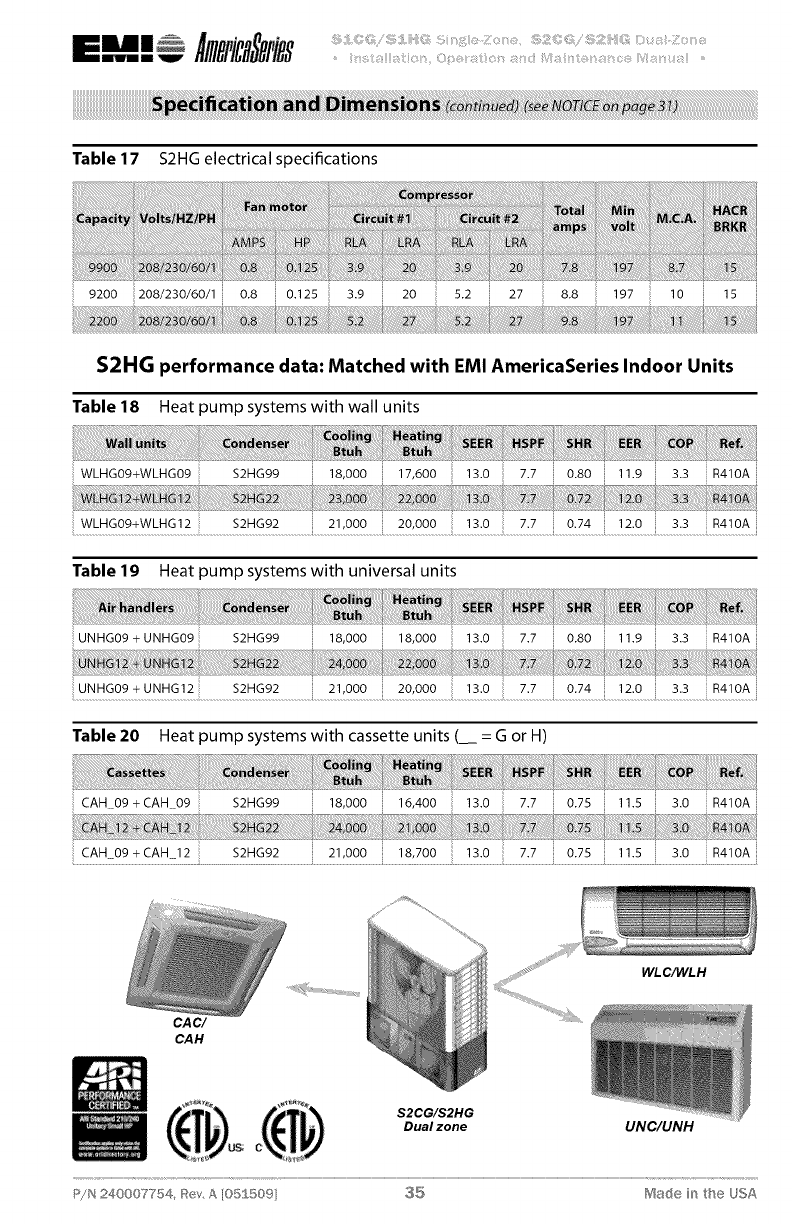
Table 17 S2HG electrical specifications
9200 208/230/60/1 0.8 0.125 3.9 20 5.2 27 8.8 i! 197 10 15
S2HG performance data: Matched with EMI AmericaSeries Indoor Units
Table 18 Heat pump systems with wall units
WLHG09+WLHG09 $2HG99
WLHG09+WLHG 12 $2HG92
18,000 17,600 13.0 7.7 0.80 11.9 3.3 R410A
21,000 20,000 13.0 7.7 0.74 12.0 3.3 R410A
Table 19 Heat pump systems with universal units
UNHG09 + UNHG09 $2HG99 18,000 18,000 13.0 7.7 0.80 11.9 3.3 R410A
UNHG09 + UNHG12 $2HG92 21,000 20,000 13.0 7.7 0.74 12.0 3.3 R410A
Table 20 Heat pump systems with cassette units (_ = G or H)
CAC/
CAH
WL C/WL H
S2CG/S2HG
Dual zone UNC/UNH
P/N 240007-/54, _ev, A [05S 509] $5 Ma(_e in the USA
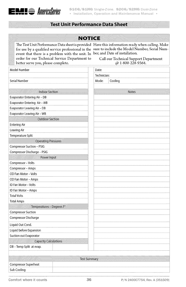
i!!!!_!_!_i_i_i!iiiiiiiiiiii_!_ii_!_i_!i_i_ii_i!!i_i_i_i_iiiiiii_i!_!!!i_!!!!_!!_!_!_!!_!!!!i!ii!_!ii_!_ii!iii_!i_ii_!i_!_!i_!i_ii_i!_ii_i!_ii_ii_i_!!_i_!!_i!_i_ii_i_ii_!i_i_ii_i_!i_ii_ii_ii_ii_il_i_i_!_i_i_i_i_i_i_i_i_i_i_i_i_i_i_i_i_i_i_i_!_!_!_!_!i_i_i_i_i_i_i_i_!ii_!_!!i_:_!_i_i_!_!_!_!_!_!_i_!i_i_i_i_!_i_!i_i_!_!!ii_!_!_!!_i_i!i_i!i!!_!_I_!I_I_!I_II_I!!II!I!_II_II_i_!!_i_!!_i!!ii!ii!ii!ii!ii_i!_ii_i!_ii_ii_ii_i_i!ii!ii!i_!_!_!_!_!_i_i_iiiii!i_i!_!i_i!_!_!_ii_i_ii_ii_i_i_i_i_i_i_i_i_i_i!i!i!i!i!_i_i!_i_!_i_i_i!_i!_i_i_i_ii_iiiiiiiiiiiiiiii_ii_ii_ii_ii_ii_ii_ii_ii_ii_ii_iiiii_iiiii_!_!_!!i!!i
Technician:
,Se_!a!Number.................................................................................................................................._ iMede! ....................c°°!!n_! .................................................................................................
Evaporator Entering Air - WB
Evaporator Leaving Air- DB i
Leaving Air
Compressor Suction - PSIG
Compressor - Volts
.................................................................................................................................................................................................................................................................................................................................................................................................
_OD FanMotor - Volts
ID FanMotor- Amps
:................................................................................................................................................................._ .....................................................................................................................
Total Volts
Compressor Suction
Compressor Discharge
Liquid Out Cond. i.......................................................................................................................................................................
Liquid before Expansion
Suction out Evaporator
DB- Temp Split at evap.
Compressor Superheat
Comfort where it cou_'_ts $G P!N 240007754, _ev A [05£50%
_/N 240007754, _tev, A [05ff 5©9 $7 Made in the USA
Bi iW ....:iiiii_!i,iii!iiiiii:_i:iiiiiI::i_i_i_= 0 iii[Jiii_i_¸_ii!_iI:!!0 i_i__!i_ii:__i:li!_ii¸_!i!i_ii!ii_i!:i_!!i__ii!iii_ii_i;;ili!_i!_¢_I_ii_iii_i_!i_ii!i_ii =_
Comfort where it cou_'_ts 38 P!N 240007754, tSev A [05£50%
_£N 240007754, _tev, A [05ff 5©9 $9 Matte in the USA
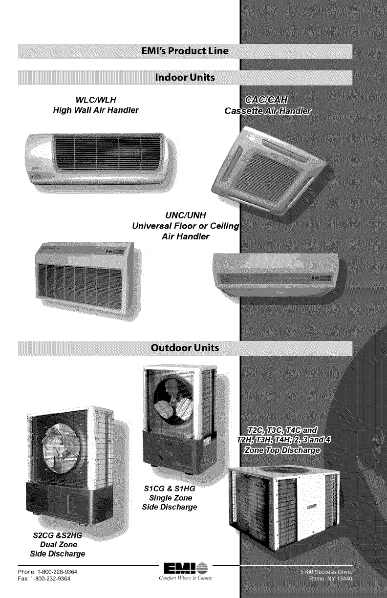
WLC/WL H
High Wall Air Handler
UNC/UNH
Air Handler
SICG
Single Zone
Side Discharge
S2CG &,
Dual Zone
Side Discharge
