EMS Technologies Canada A781-MK2 A350 Satellite Data Unit User Manual
EMS Technologies Canada, Ltd. A350 Satellite Data Unit
UserManual.wiki
>
EMS Technologies Canada
>
A781 MK2 User Manual
Users Manual
Navigation menu
Upload a User Manual
Namespaces
Wiki Guide
HTML
PDF
Info
Views
User Manual
Discussion / Help
Navigation
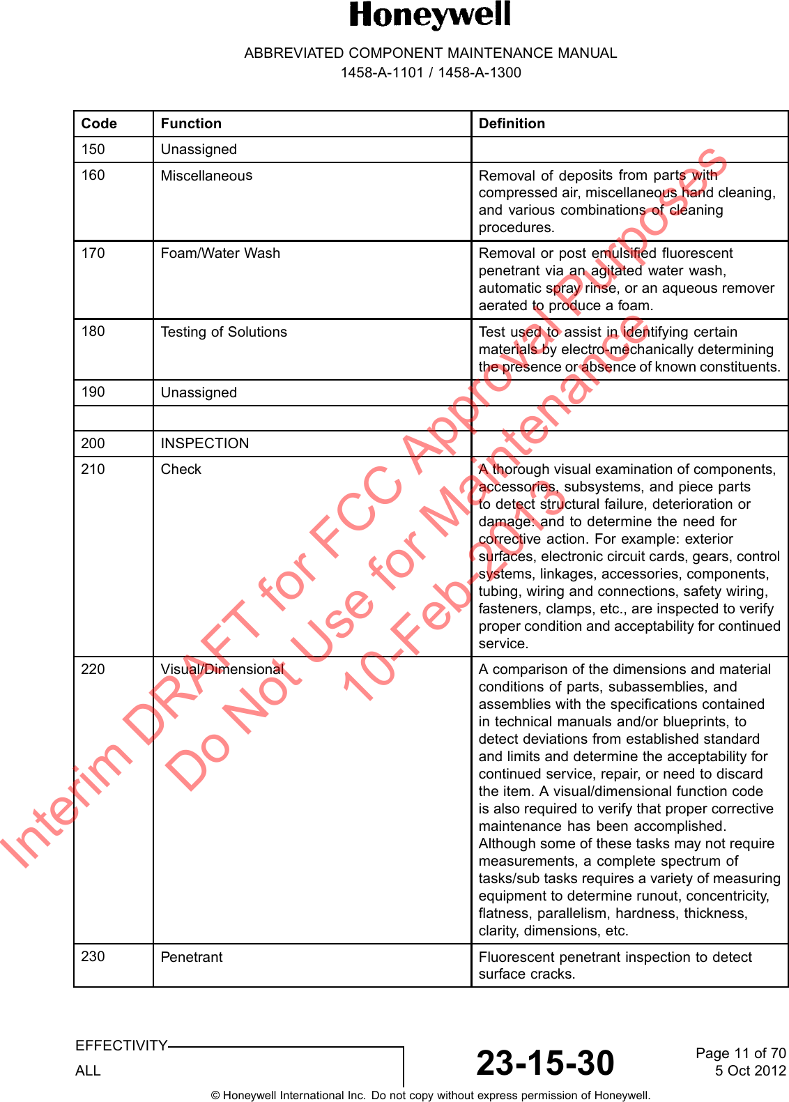
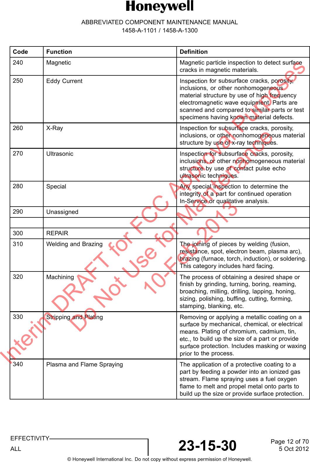
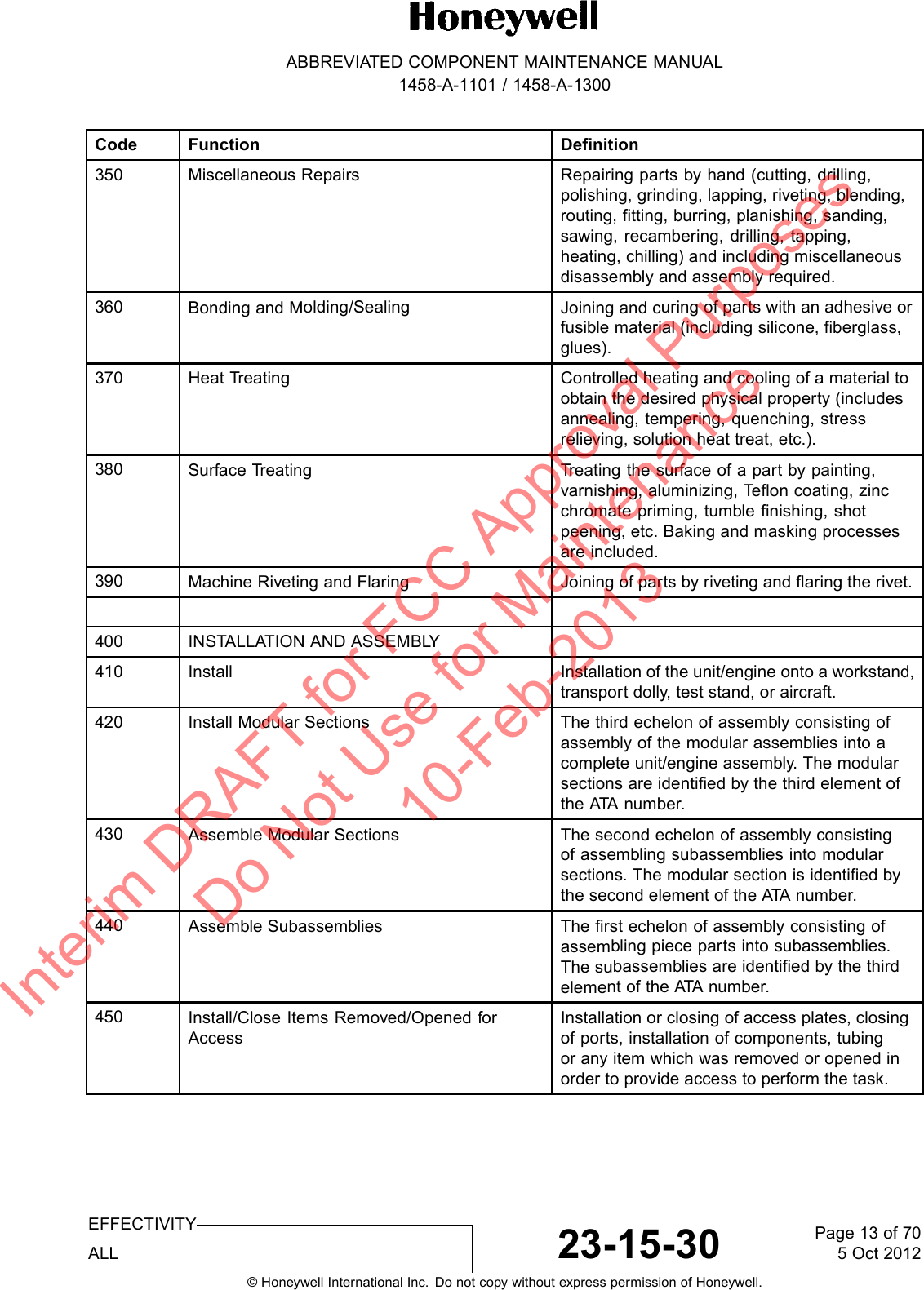
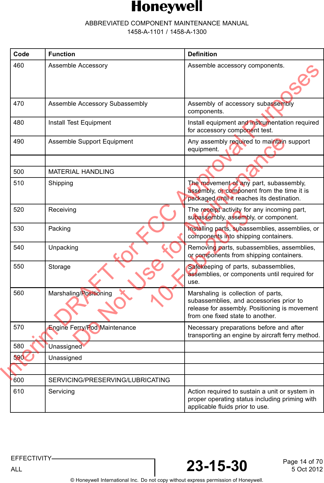
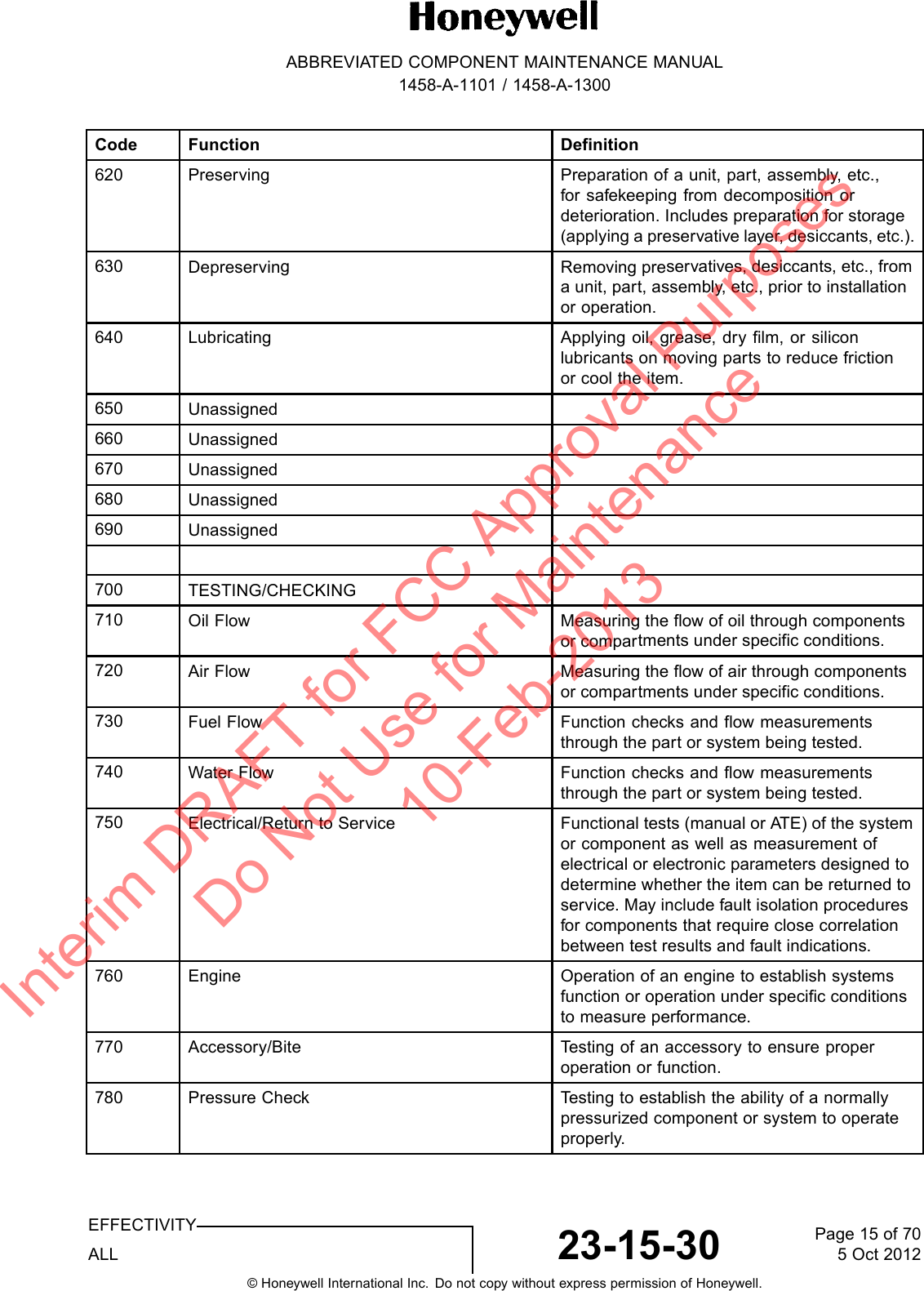
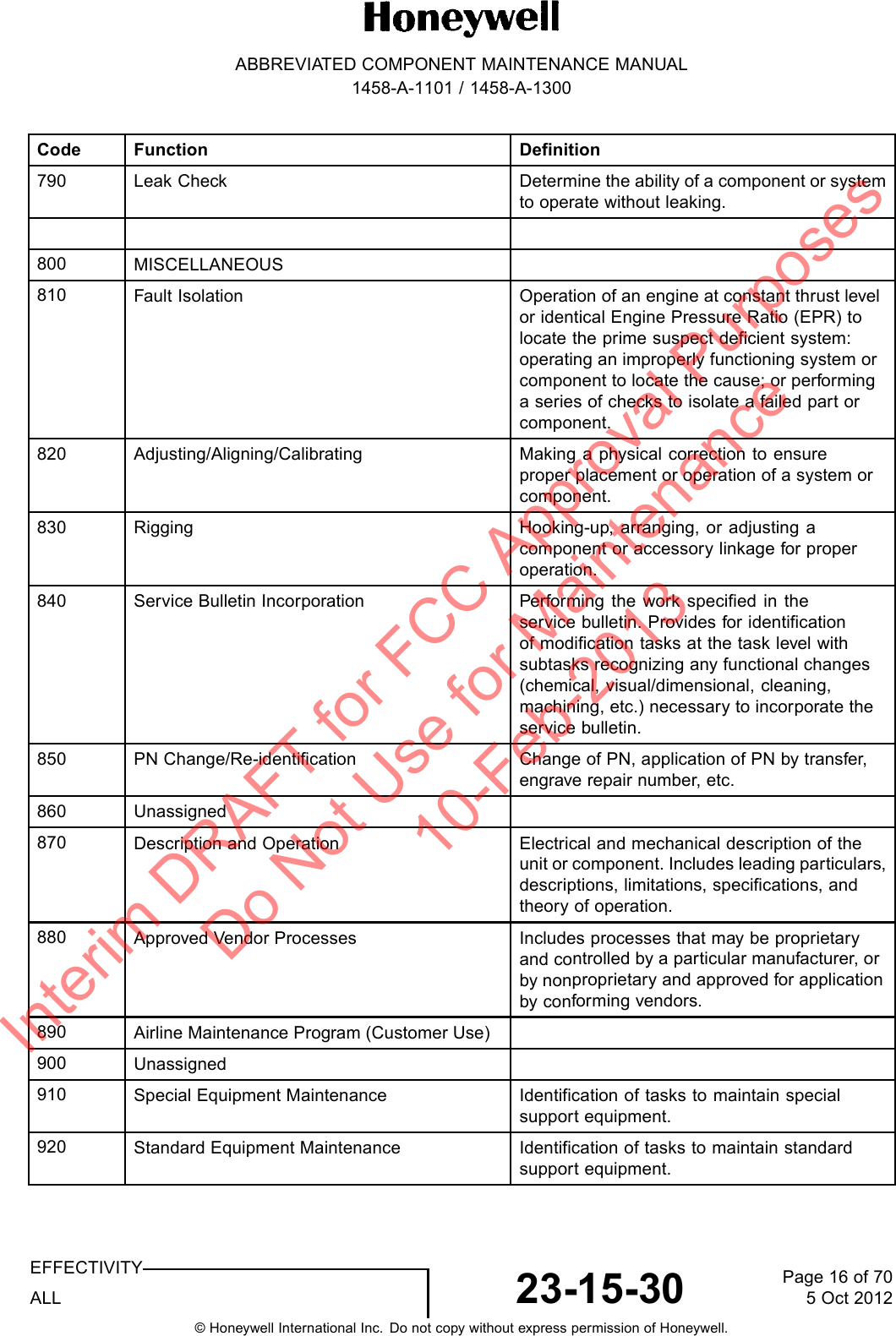
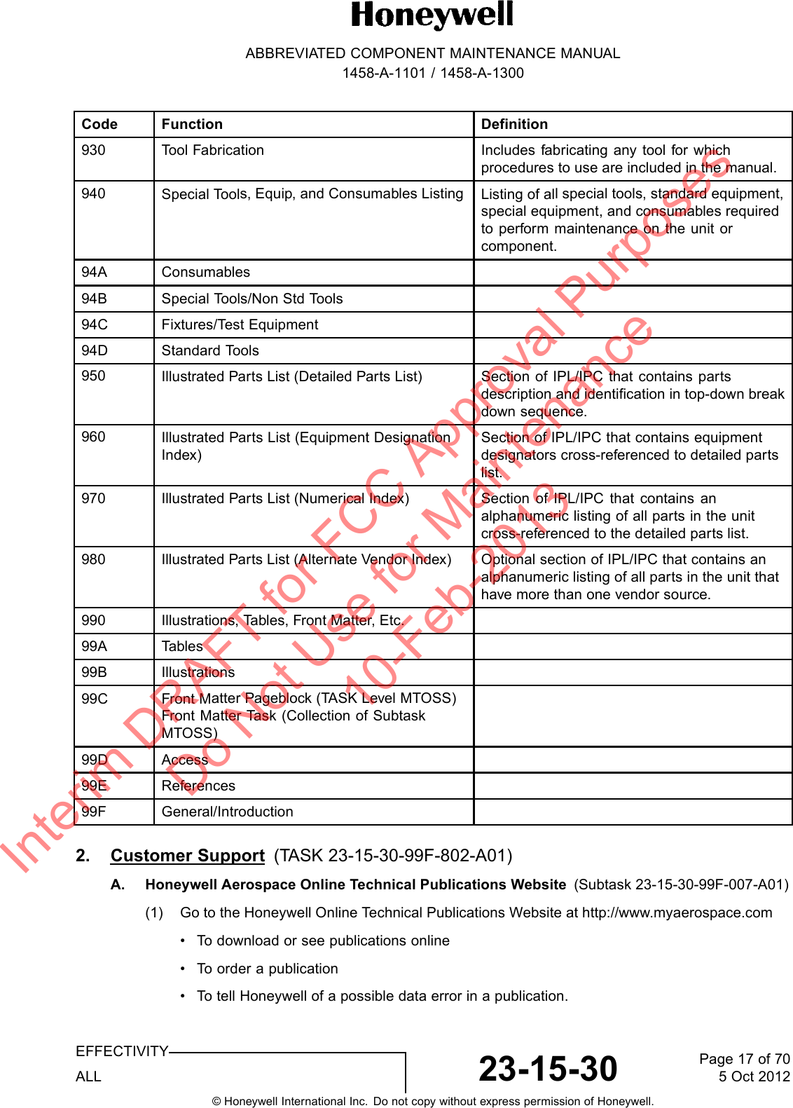
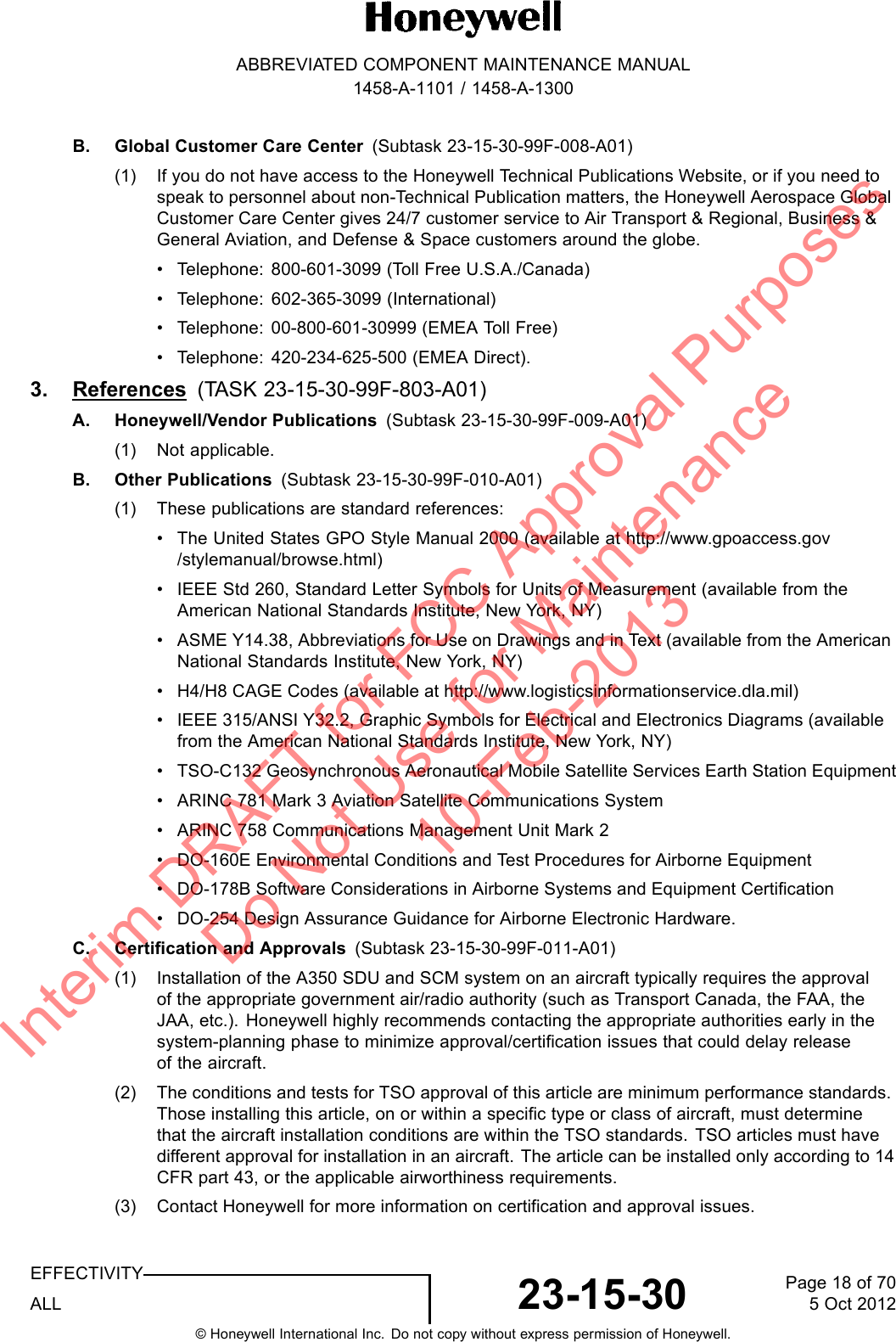


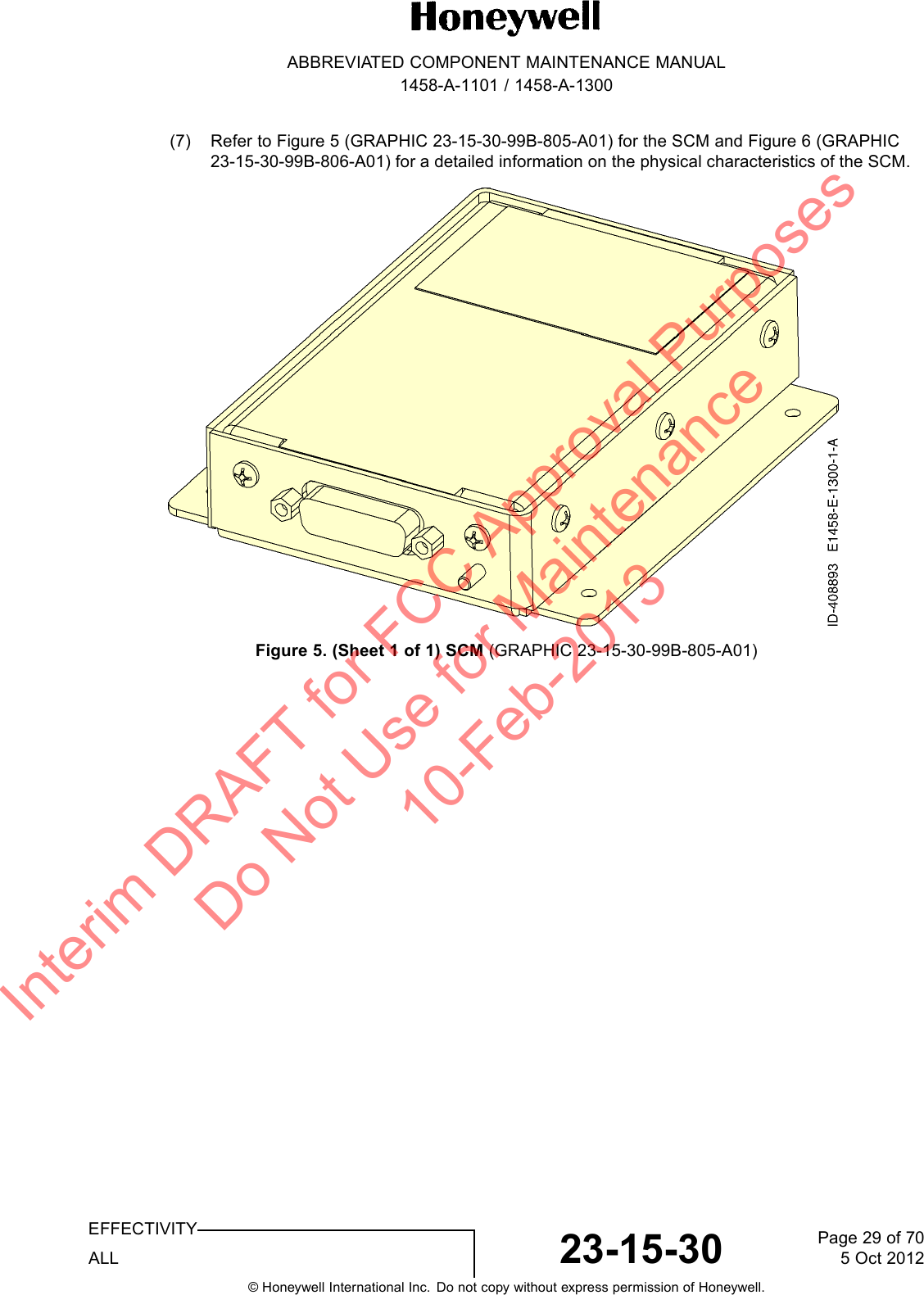

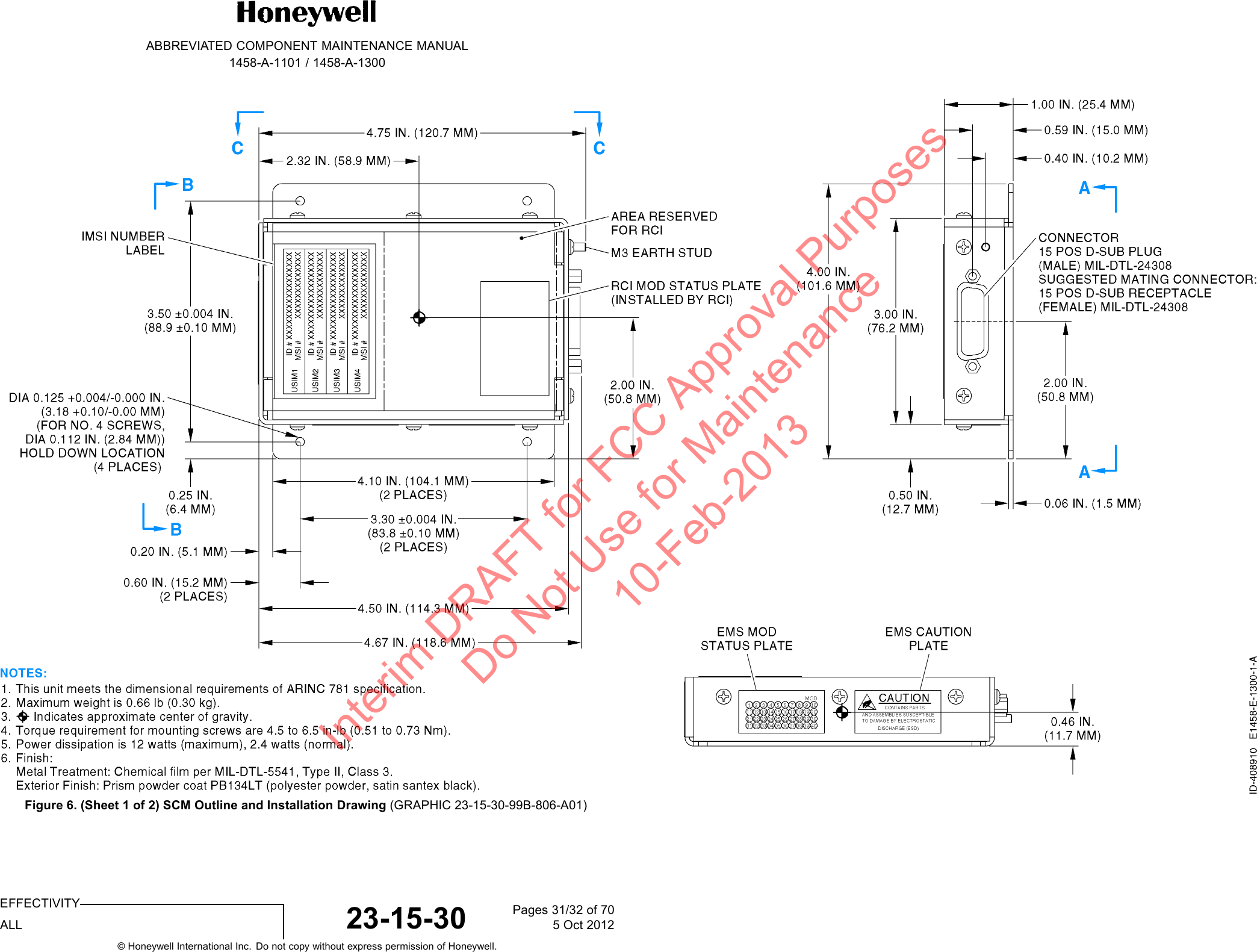

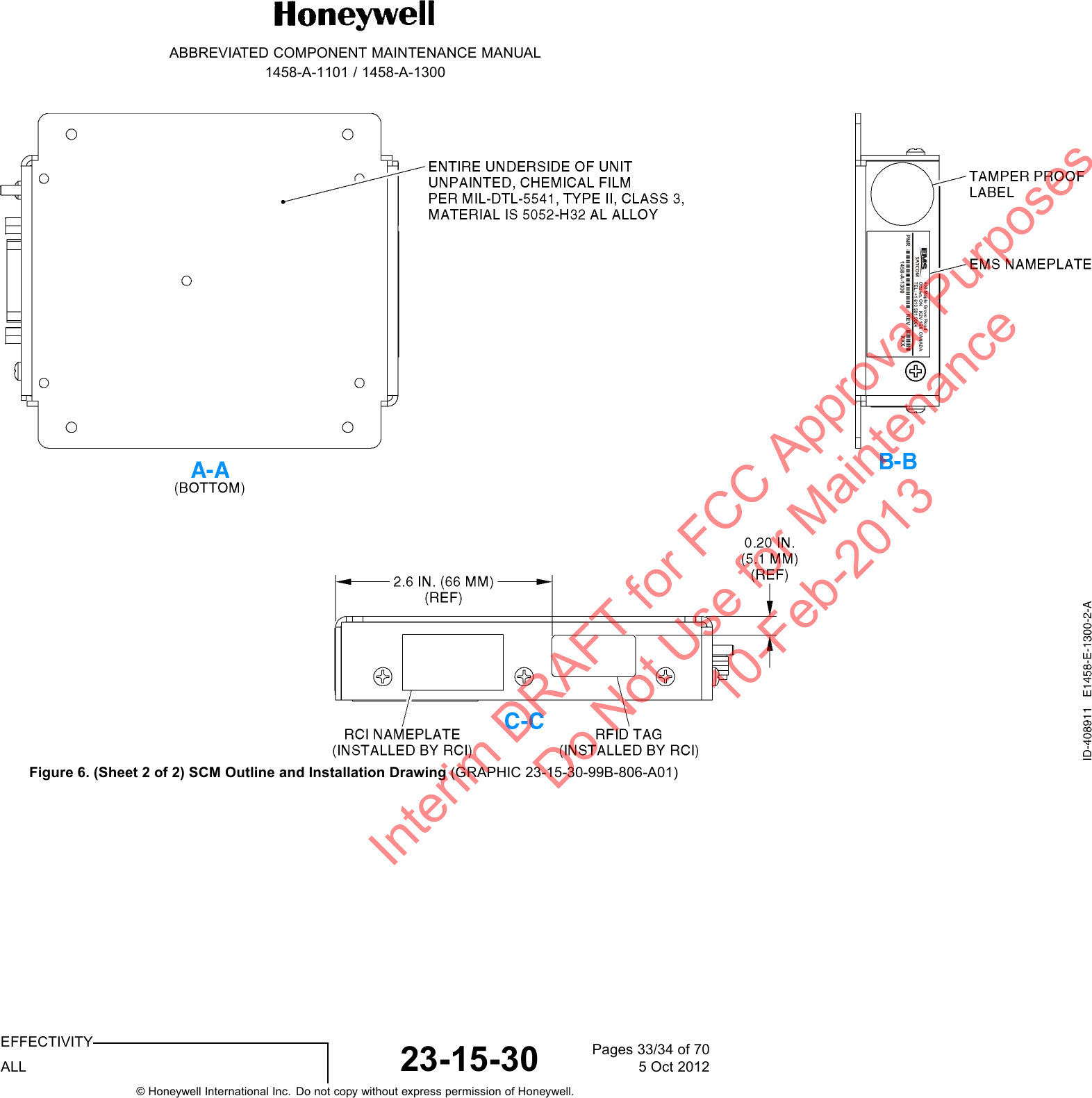

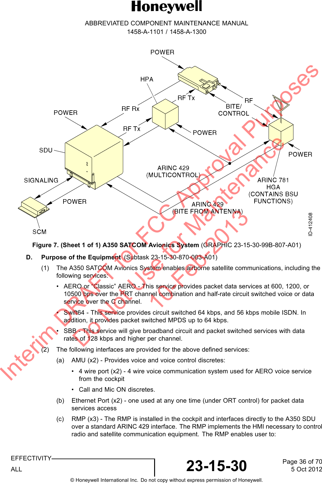
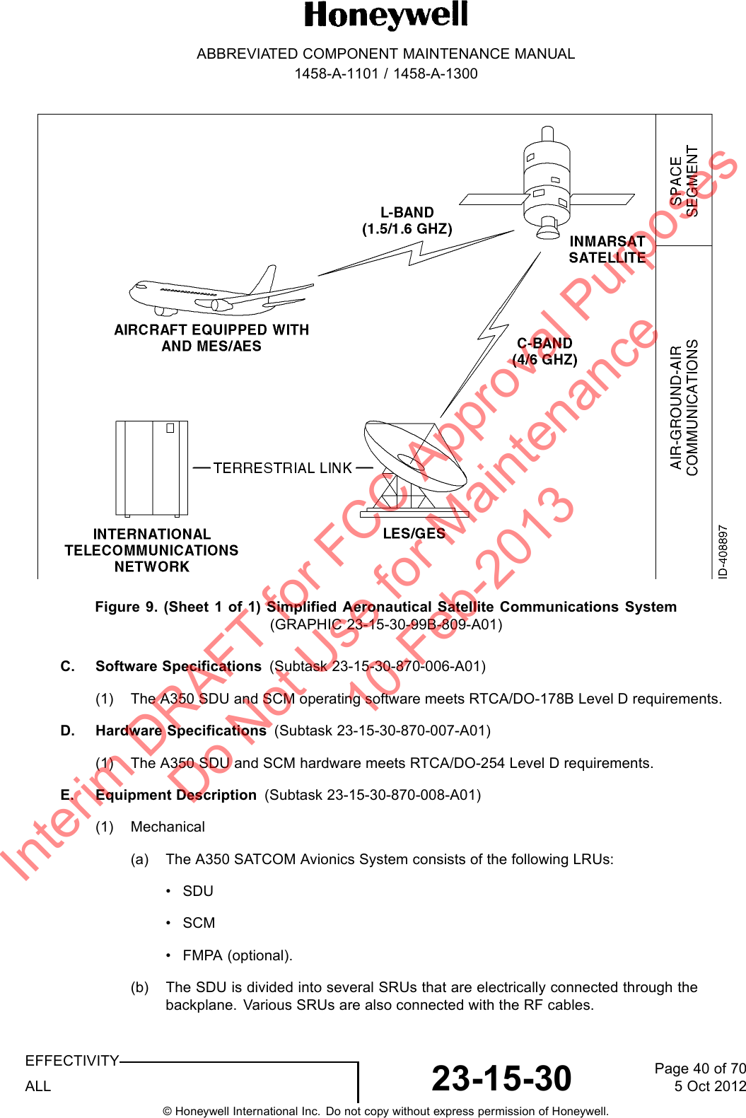
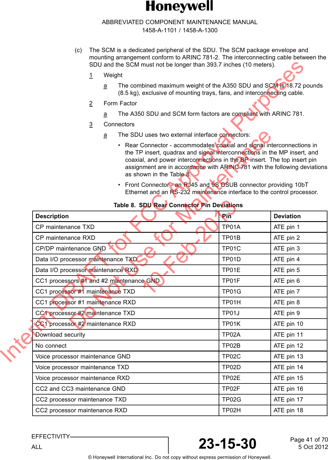
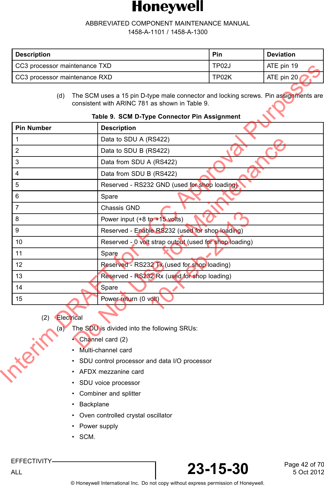
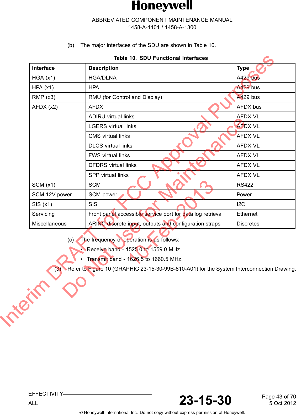

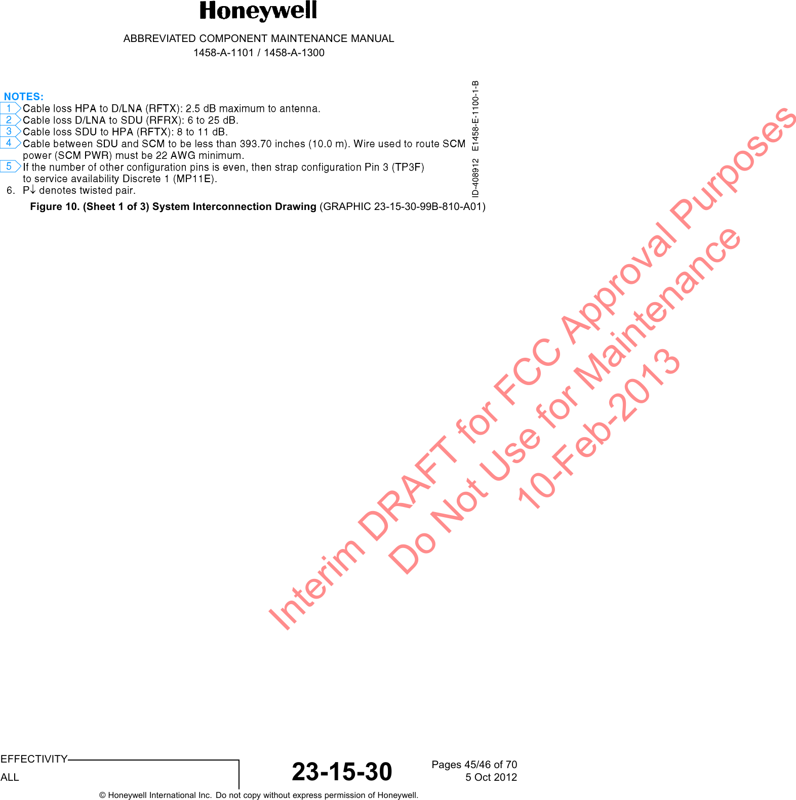

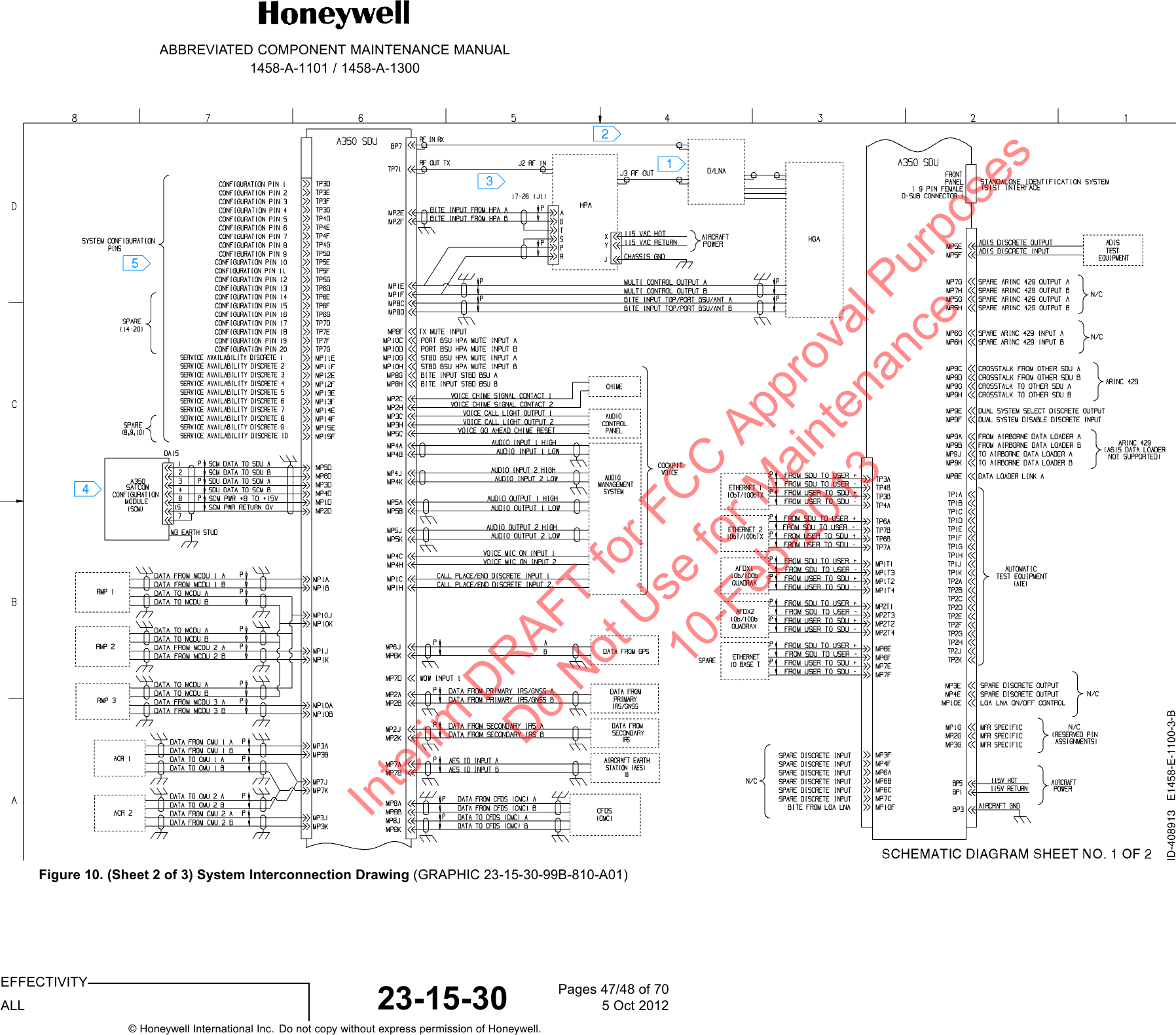

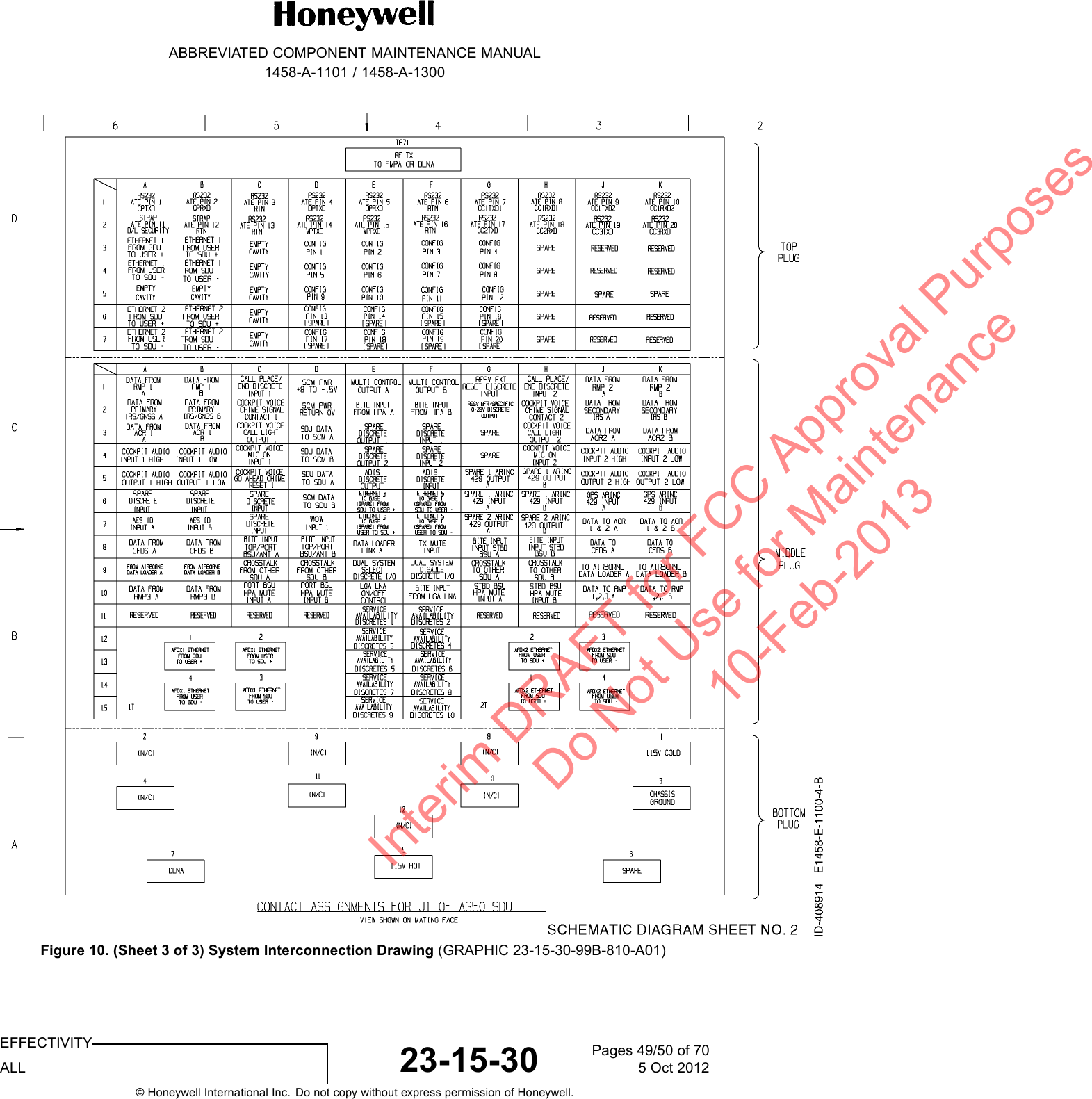

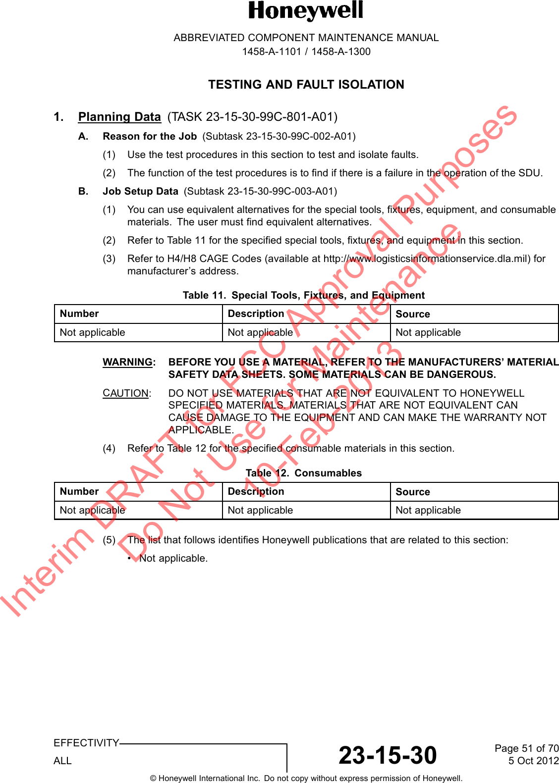
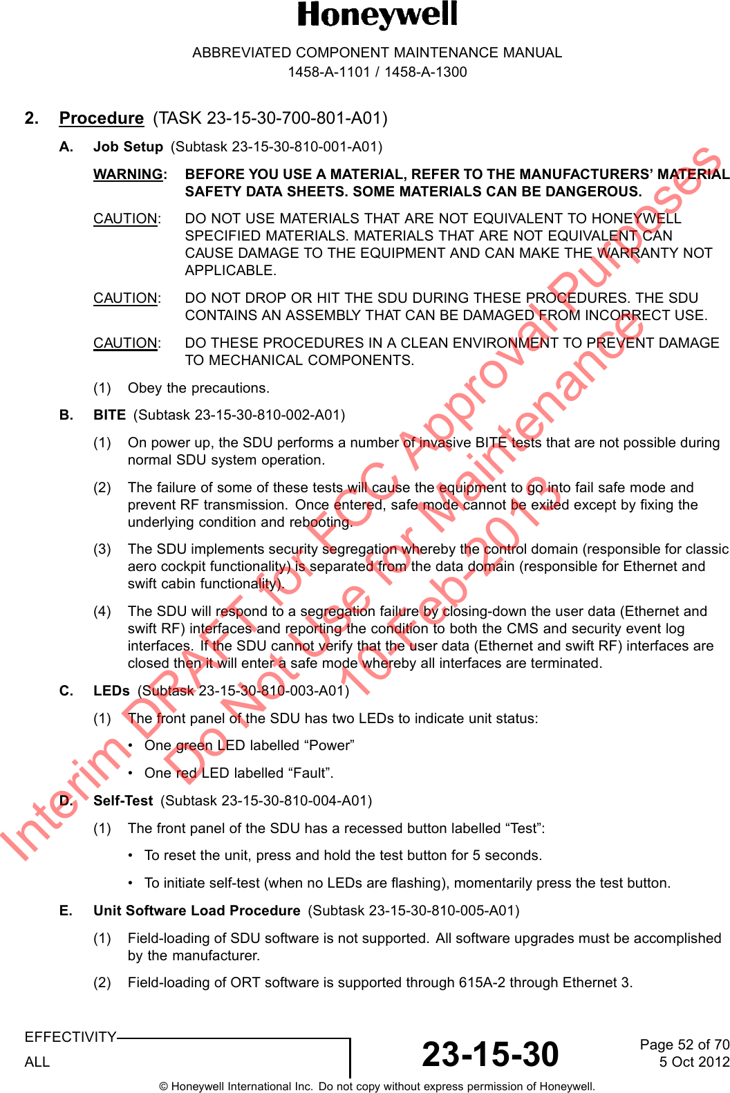
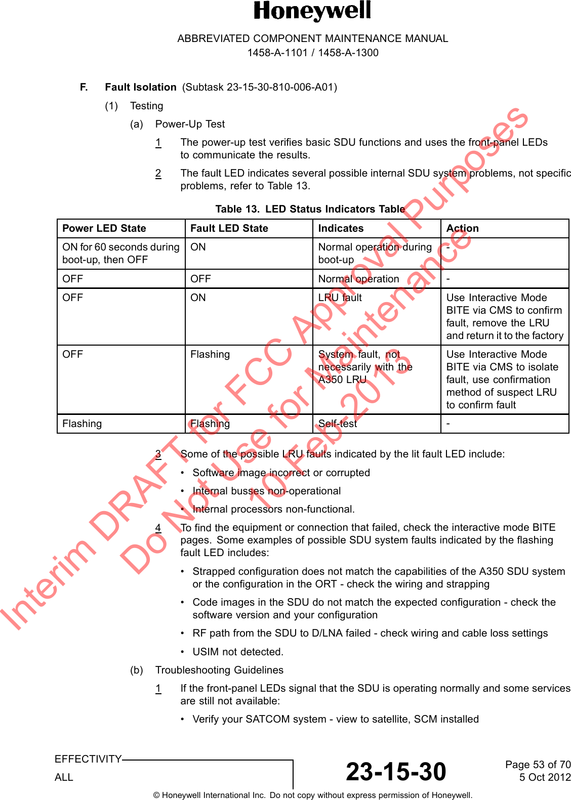
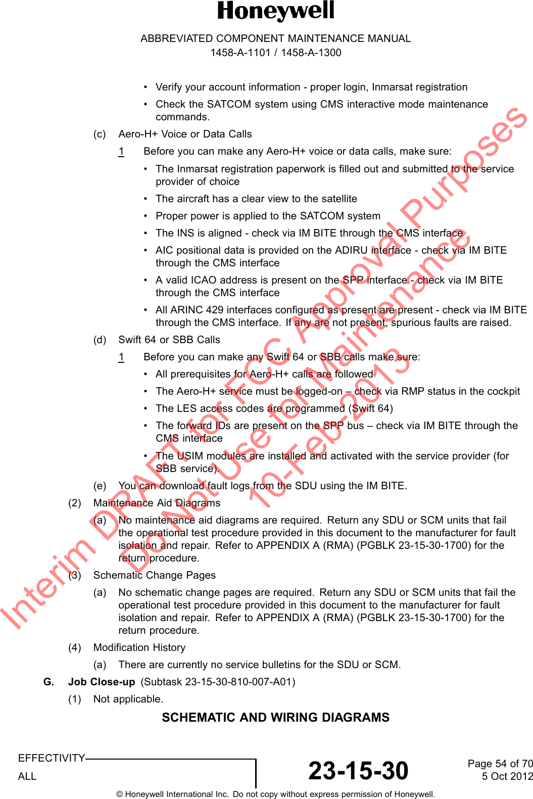
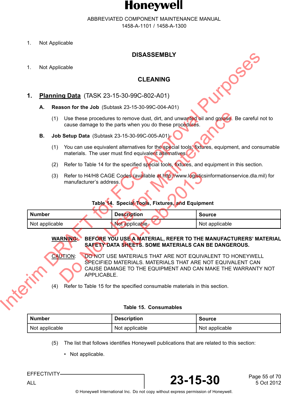
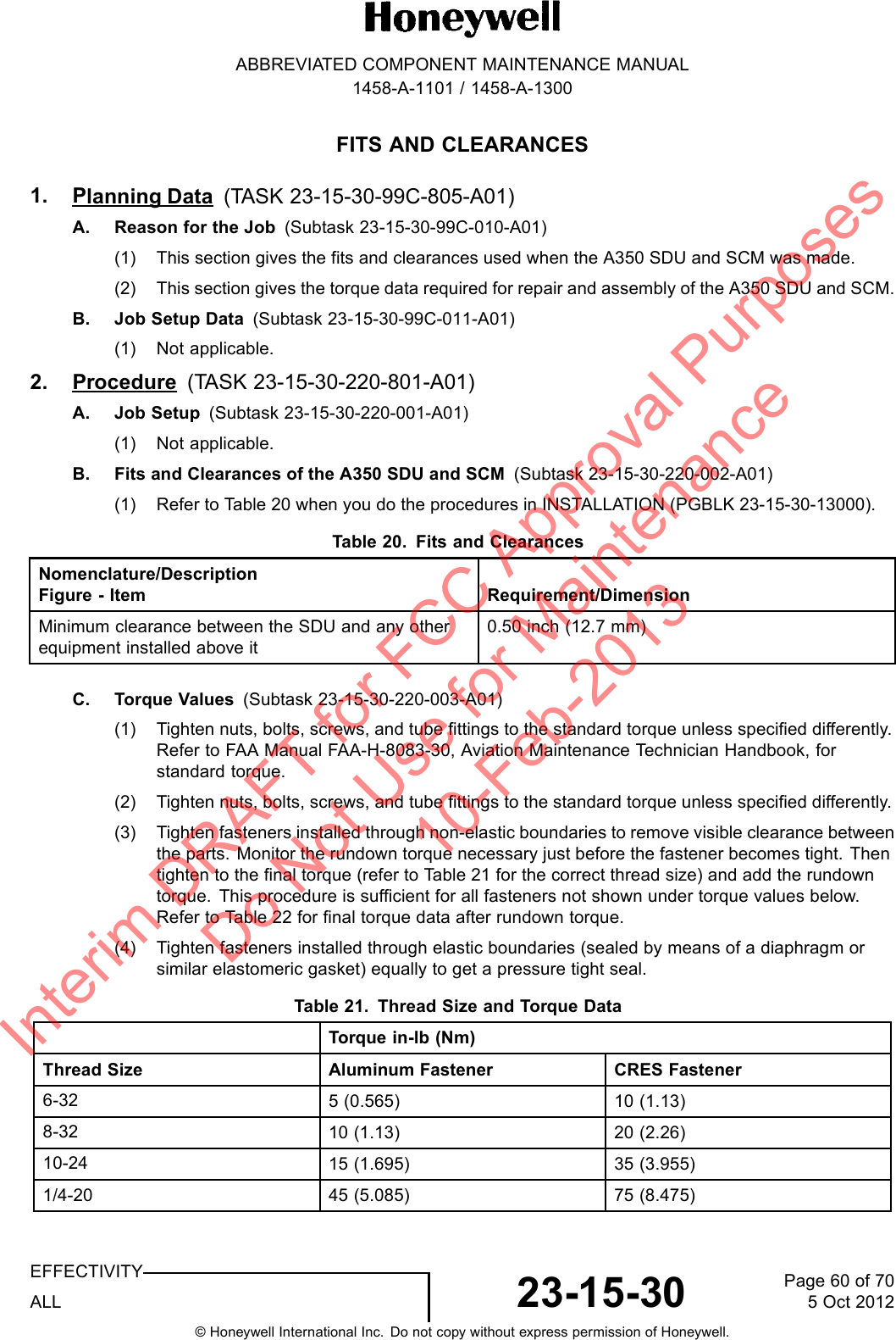
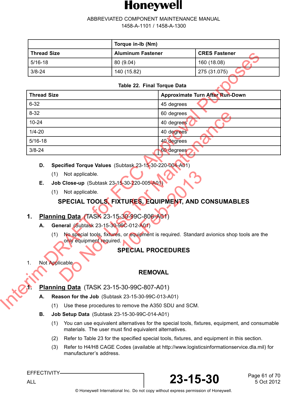
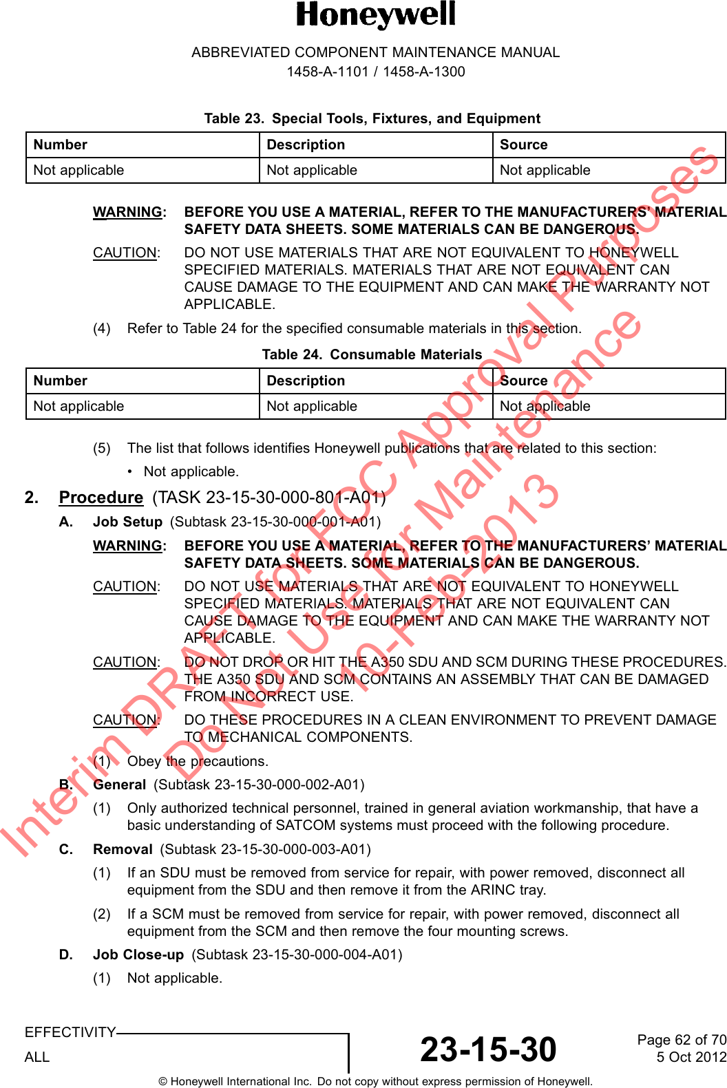
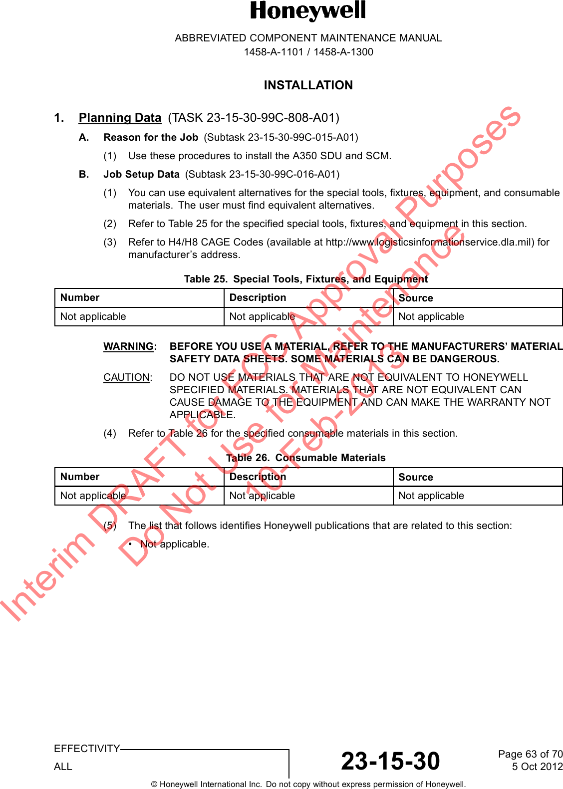
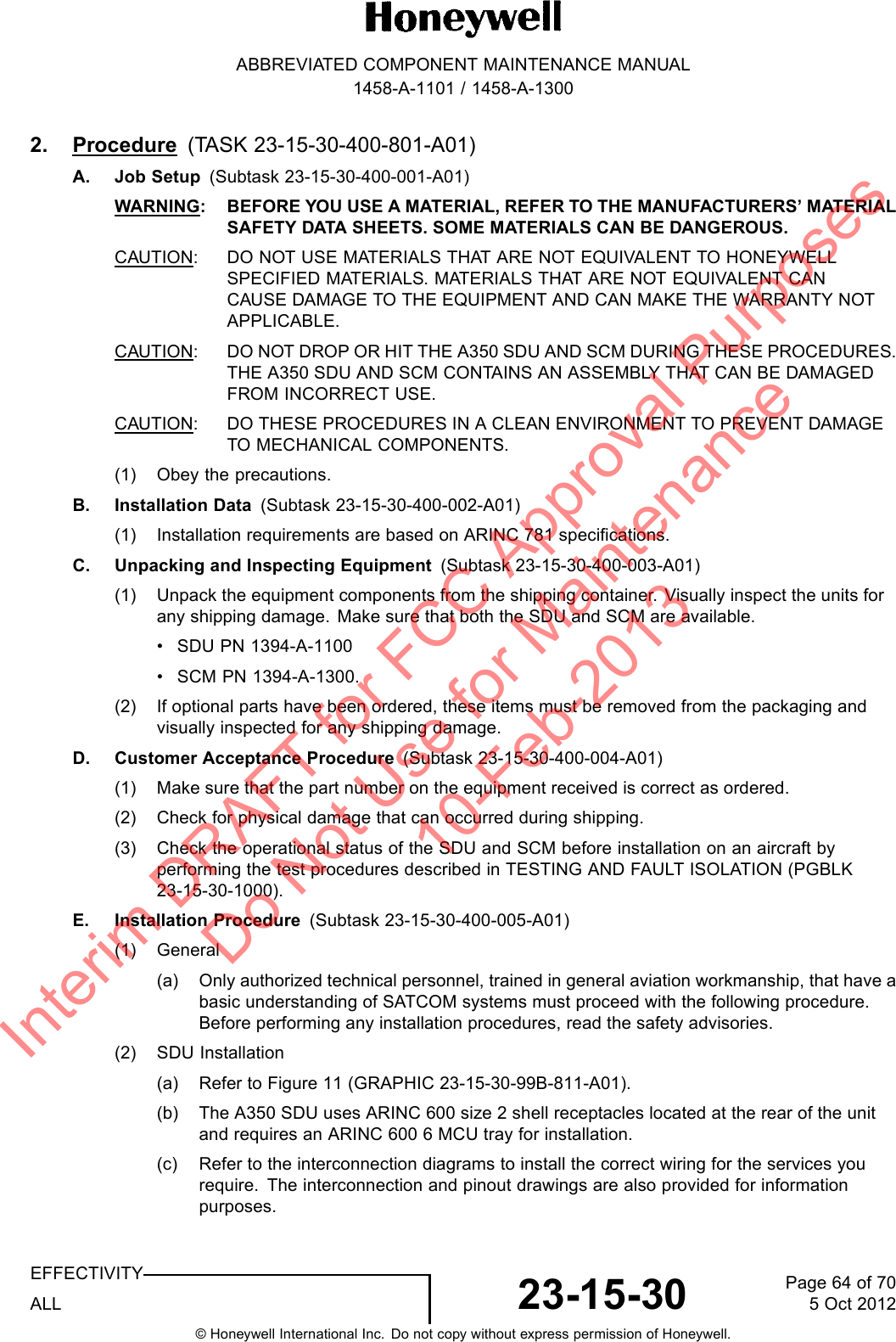
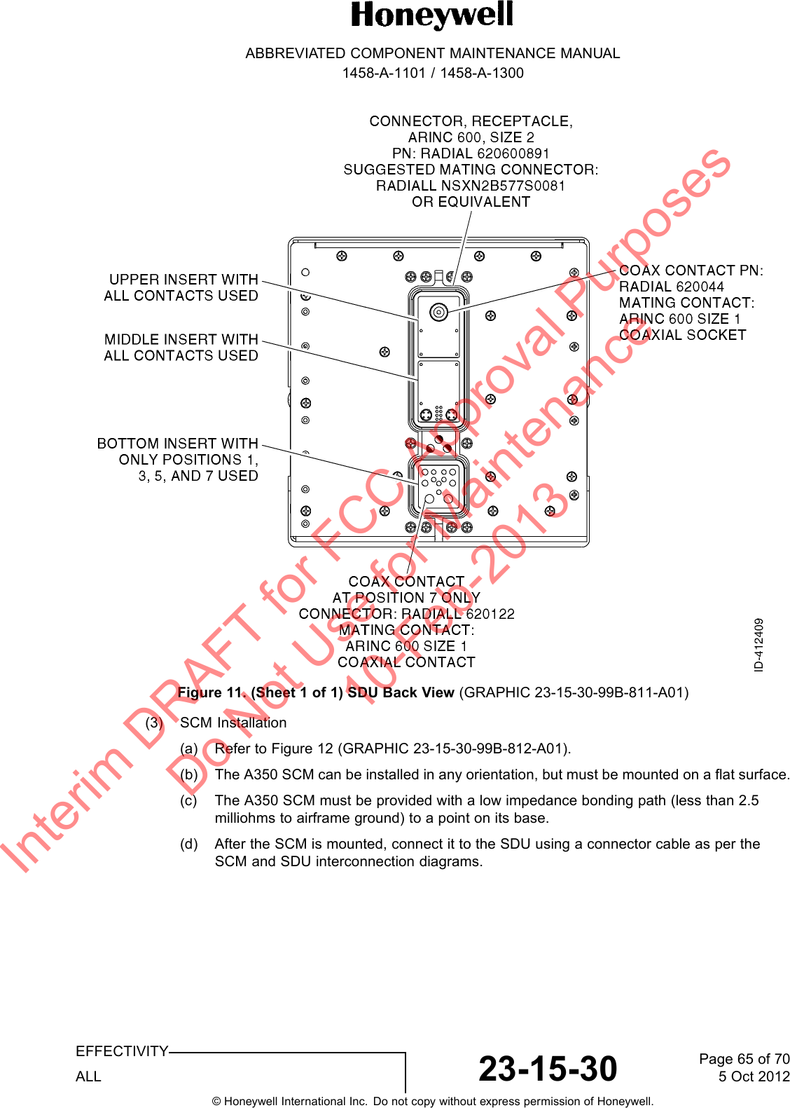
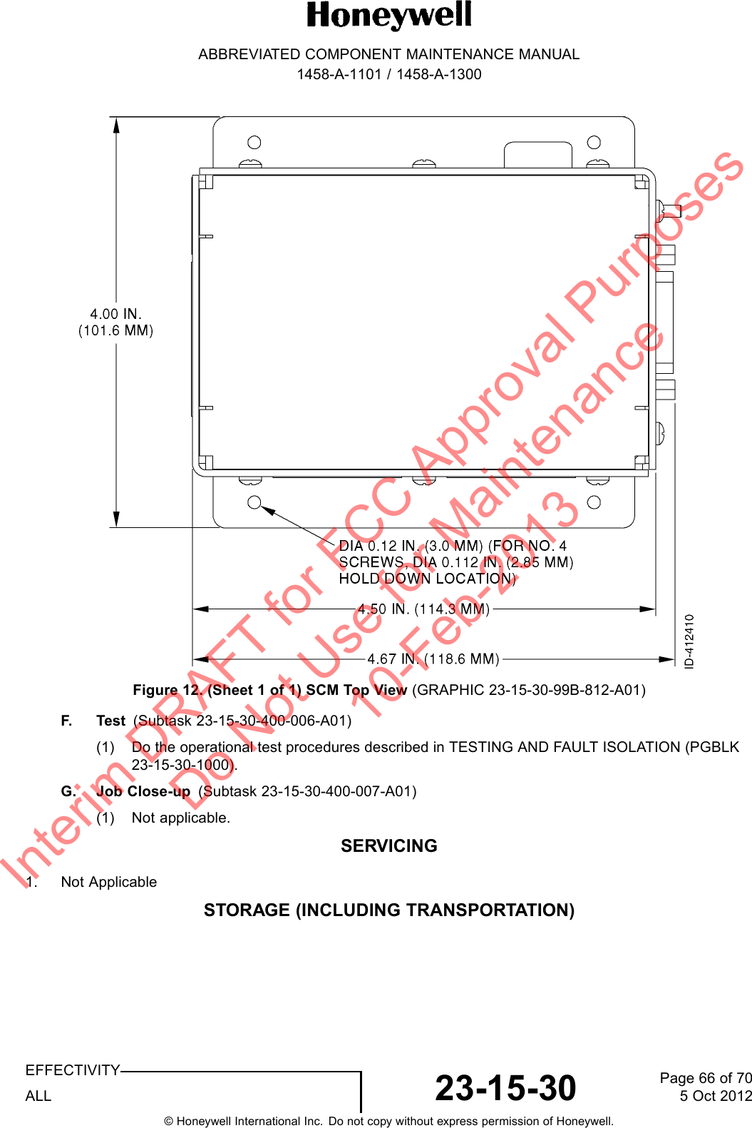
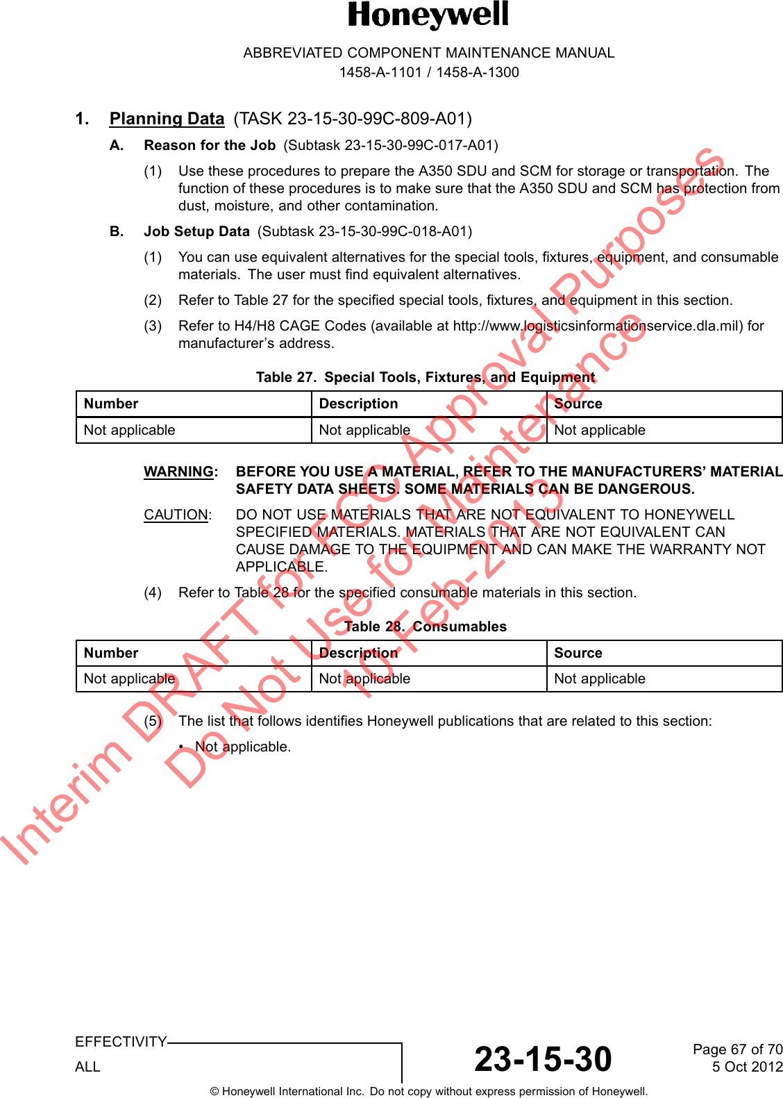
![ABBREVIATED COMPONENT MAINTENANCE MANUAL1458-A-1101 / 1458-A-13002. Procedure (TASK 23-15-30-550-801-A01)A. Job Setup (Subtask 23-15-30-550-001-A01)WARNING: BEFORE YOU USE A MATERIAL, REFER TO THE MANUFACTURERS’ MATERIALSAFETY DATA SHEETS. SOME MATERIALS CAN BE DANGEROUS.CAUTION: DO NOT USE MATERIALS THAT ARE NOT EQUIVALENT TO HONEYWELLSPECIFIED MATERIALS. MATERIALS THAT ARE NOT EQUIVALENT CANCAUSE DAMAGE TO THE EQUIPMENT AND CAN MAKE THE WARRANTY NOTAPPLICABLE.CAUTION: DO NOT DROP OR HIT THE A350 SDU AND SCM DURING THESE PROCEDURES.THE A350 SDU AND SCM CONTAINS AN ASSEMBLY THAT CAN BE DAMAGEDFROM INCORRECT USE.CAUTION: DO THESE PROCEDURES IN A CLEAN ENVIRONMENT TO PREVENT DAMAGETO MECHANICAL COMPONENTS.(1) Obey the precautions.B. Preservation (Subtask 23-15-30-550-002-A01)(1) Not applicable.C. Packing (Subtask 23-15-30-550-003-A01)(1) Not applicable.D. Storage (Subtask 23-15-30-550-004-A01)(1) Store the A350 SDU and SCM equipment in a cool, dry place [ground survival temperaturerange is 67 to 185 F( 55 to +85 C)] in its original shipping container.E. Transportation (Subtask 23-15-30-550-005-A01)(1) Not applicable.F. J o b C l o s e - up (Subtask 23-15-30-550-006-A01)(1) Not applicable.REWORK1. Planning Data (TASK 23-15-30-99F-806-A01)A. General (Subtask 23-15-30-99F-014-A01)(1) Rework is not supported in the field. Return any SDU or SCM units that fail the test proceduresprovided in this document to the manufacturer for fault isolation and repair. Refer to APPENDIXA (RMA) (PGBLK 23-15-30-1700) for the return procedure.APPENDIX A (RMA)1. Planning Data(TASK 23-15-30-99F-807-A01)A. General (Subtask 23-15-30-99C-019-A01)(1) To return the equipment to Honeywell for repair, this RMA procedure must be followed. Failureto comply with this procedure can result in shipping delays and additional charges.EFFECTIVITYALL 23-15-30 Page 68 of 705 Oct 2012© Honeywell International Inc. Do not copy without express permission of Honeywell.Interim DRAFT for FCC Approval Purposes Do Not Use for Maintenance 10-Feb-2013](https://usermanual.wiki/EMS-Technologies-Canada/A781-MK2/User-Guide-1956151-Page-68.png)