EMS Technologies Canada A781-MK2 A350 Satellite Data Unit User Manual
EMS Technologies Canada, Ltd. A350 Satellite Data Unit
Users Manual

Honeywell International Inc.
400 Maple Grove Drive
Ottawa, Ontario K2V 1B8
Canada
CAGE: 38473
Telephone: (800) 601-3099 (Toll Free U.S.A./Canada)
Telephone: (602) 365-3099 (International Direct)
Website: www.myaerospace.com
Abbreviated Component Maintenance Manual
A350 SDU and SCM
Part Number CAGE
1458-A-1101 38473
1458-A-1300 38473
This document contains technical data and is subject to U.S. export regulations. These commodities, technology, or
software were exported from the United States in accordance with the export administration regulations. Diversion contrary
to U.S. law is prohibited.
ECCN: 7E994, NLR Eligible.
23-15-30
Page1of70
Publication Number D201207000045, Revision 0 Initial 5 Oct 2012
©Honeywell International Inc. Do not copy without express permission of Honeywell.
Interim DRAFT for FCC Approval Purposes
Do Not Use for Maintenance
10-Feb-2013

ABBREVIATED COMPONENT MAINTENANCE MANUAL
1458-A-1101 / 1458-A-1300
Honeywell - Confidential
THIS COPYRIGHTED WORK AND ALL INFORMATION ARE THE PROPERTY OF HONEYWELL
INTERNATIONAL INC., CONTAIN TRADE SECRETS AND MAY NOT, IN WHOLE OR IN PART, BE USED,
DUPLICATED, OR DISCLOSED FOR ANY PURPOSE WITHOUT PRIOR WRITTEN PERMISSION OF
HONEYWELL INTERNATIONAL INC. ALL RIGHTS RESERVED.
Honeywell Materials License Agreement
The documents and information contained herein ("the Materials") are the proprietary data of Honeywell
International Inc. and Honeywell Intellectual Properties Inc. (collectively "Honeywell"). These Materials
are provided for the exclusive use of Honeywell Service Centers; Honeywell-authorized repair facilities;
operators of Honeywell aerospace products subject to an applicable product support agreement, their
wholly owned-subsidiaries or a formally designated third party service provider; and direct recipients of
Materials from Honeywell’s Aerospace Technical Publication Distribution. The terms and conditions of
this License Agreement govern your use of these Materials, except to the extent that any terms and
conditions of another applicable agreement with Honeywell regarding the operation, maintenance, or
repair of Honeywell aerospace products conflict with the terms and conditions of this License Agreement,
in which case the terms and conditions of the other agreement will govern. However, this License
Agreement will govern in the event of a conflict between its terms and conditions and those of a purchase
order or acknowledgement.
1. License Grant - If you are a party to an applicable product support agreement, a Honeywell Service
Center agreement, or an authorized repair facility agreement, Honeywell hereby grants you a limited,
non-exclusive license to use these Materials to operate, maintain, or repair Honeywell aerospace products
only in accordance with that agreement.
If you are a direct recipient of these Materials from Honeywell’s Aerospace Technical Publication
Distribution and are not a party to an agreement related to the operation, maintenance or repair of
Honeywell aerospace products, Honeywell hereby grants you a limited, non-exclusive license to use
these Materials to maintain or repair the subject Honeywell aerospace products only at the facility to
which these Materials have been shipped ("the Licensed Facility"). Transfer of the Materials to another
facility owned by you is permitted only if the original Licensed Facility retains no copies of the Materials
and you provide prior written notice to Honeywell.
2. Rights In Materials - Honeywell retains all rights in these Materials and in any copies thereof that are not
expressly granted to you, including all rights in patents, copyrights, trademarks, and trade secrets. No
license to use any Honeywell trademarks or patents is granted under this License Agreement.
3. Confidentiality - You acknowledge that these Materials contain information that is confidential and
proprietary to Honeywell. You agree to take all reasonable efforts to maintain the confidentiality of these
Materials.
4. Assignment And Transfer - This License Agreement may be assigned to a formally designated service
designee or transferred to a subsequent owner or operator of an aircraft containing the subject Honeywell
aerospace products. However, the recipient of any such assignment or transfer must assume all of
your obligations under this License Agreement. No assignment or transfer shall relieve any party of
any obligation that such party then has hereunder.
5. Copies of Materials - Unless you have the express written permission of Honeywell, you may not
make or permit making of copies of the Materials. Notwithstanding the foregoing, you may make copies
of only portions of the Material for your internal use. You agree to return the Materials and any copies
thereof to Honeywell upon the request of Honeywell.
6. Term - This License Agreement is effective until terminated as set forth herein. This License Agreement
will terminate immediately, without notice from Honeywell, if you fail to comply with any provision of this
23-15-30 Page2of70
5 Oct 2012
© Honeywell International Inc. Do not copy without express permission of Honeywell.
Interim DRAFT for FCC Approval Purposes
Do Not Use for Maintenance
10-Feb-2013

ABBREVIATED COMPONENT MAINTENANCE MANUAL
1458-A-1101 / 1458-A-1300
License Agreement or will terminate simultaneously with the termination or expiration of your applicable
product support agreement, authorized repair facility agreement, or your formal designation as a third party
service provider. Upon termination of this License Agreement, you will return these Materials to Honeywell
without retaining any copies and will have one of your authorized officers certify that all Materials have
been returned with no copies retained.
7. Remedies - Honeywell reserves the right to pursue all available remedies and damages resulting from
a breach of this License Agreement.
8. Limitation of Liability - Honeywell does not make any representation regarding the use or sufficiency of
the Materials. THERE ARE NO OTHER WARRANTIES, WHETHER WRITTEN OR ORAL, EXPRESS,
IMPLIED OR STATUTORY, INCLUDING, BUT NOT LIMITED TO, (i) WARRANTIES ARISING FROM
COURSE OF PERFORMANCE, DEALING, USAGE, OR TRADE, WHICH ARE HEREBY EXPRESSLY
DISCLAIMED, OR (ii) WARRANTIES AGAINST INFRINGEMENT OF INTELLECTUAL PROPERTY
RIGHTS OF THIRD PARTIES, EVEN IF HONEYWELL HAS BEEN ADVISED OF ANY SUCH
INFRINGEMENT. IN NO EVENT WILL HONEYWELL BE LIABLE FOR ANY INCIDENTAL DAMAGES,
CONSEQUENTIAL DAMAGES, SPECIAL DAMAGES, INDIRECT DAMAGES, LOSS OF PROFITS, LOSS
OF REVENUES, OR LOSS OF USE, EVEN IF INFORMED OF THE POSSIBILITY OF SUCH DAMAGES.
TO THE EXTENT PERMITTED BY APPLICABLE LAW, THESE LIMITATIONS AND EXCLUSIONS WILL
APPLY REGARDLESS OF WHETHER LIABILITY ARISES FROM BREACH OF CONTRACT, WARRANTY,
TORT (INCLUDING BUT NOT LIMITED TO NEGLIGENCE), BY OPERATION OF LAW, OR OTHERWISE.
9. Controlling Law - This License shall be governed and construed in accordance with the laws of the
State of New York without regard to the conflicts of laws provisions thereof. This license sets forth the
entire agreement between you and Honeywell and may only be modified by a writing duly executed by
the duly authorized representatives of the parties.
Safety Advisory
WARNING: BEFORE THE MATERIALS CALLED OUT IN THIS PUBLICATION ARE USED, KNOW THE
HANDLING, STORAGE AND DISPOSAL PRECAUTIONS RECOMMENDED BY THE MANUFACTURER
OR SUPPLIER. FAILURE TO OBEY THE MANUFACTURERS’ OR SUPPLIERS’ RECOMMENDATIONS
CAN RESULT IN PERSONAL INJURY OR DISEASE.
This publication describes physical and chemical processes which can make it necessary to use chemicals,
solvents, paints, and other commercially available materials. The user of this publication must get the
Material Safety Data Sheets (OSHA Form 174 or equivalent) from the manufacturers or suppliers of the
materials to be used. The user must know the manufacturer/ supplier data and obey the procedures,
recommendations, warnings and cautions set forth for the safe use, handling, storage, and disposal
of the materials.
Warranty/Liability Advisory
WARNING: HONEYWELL ASSUMES NO RESPONSIBILITY FOR ANY HONEYWELL EQUIPMENT
WHICH IS NOT MAINTAINED AND/OR REPAIRED IN ACCORDANCE WITH HONEYWELL’S
PUBLISHED INSTRUCTIONS AND/OR HONEYWELL’S FAA/SFAR 36 REPAIR AUTHORIZATION.
NEITHER DOES HONEYWELL ASSUME RESPONSIBILITY FOR SPECIAL TOOLS AND TEST
EQUIPMENT FABRICATED BY COMPANIES OTHER THAN HONEYWELL.
WARNING: INCORRECTLY REPAIRED COMPONENTS CAN AFFECT AIRWORTHINESS OR
DECREASE THE LIFE OF THE COMPONENTS. INCORRECTLY FABRICATED SPECIAL TOOLING
OR TEST EQUIPMENT CAN RESULT IN DAMAGE TO THE PRODUCT COMPONENTS OR GIVE
UNSATISFACTORY RESULTS.
23-15-30 Page3of70
5 Oct 2012
© Honeywell International Inc. Do not copy without express permission of Honeywell.
Interim DRAFT for FCC Approval Purposes
Do Not Use for Maintenance
10-Feb-2013

ABBREVIATED COMPONENT MAINTENANCE MANUAL
1458-A-1101 / 1458-A-1300
Copyright - Notice
Copyright 2012 Honeywell International Inc. All rights reserved.
Honeywell is a registered trademark of Honeywell International Inc.
All other marks are owned by their respective companies.
THIS IS THE CMM FOSI - DATE: CMM FOSI - 20080523, VERSION 0019 (GBB)
23-15-30 Page4of70
5 Oct 2012
© Honeywell International Inc. Do not copy without express permission of Honeywell.
Interim DRAFT for FCC Approval Purposes
Do Not Use for Maintenance
10-Feb-2013
ABBREVIATED COMPONENT MAINTENANCE MANUAL
1458-A-1101 / 1458-A-1300
TRANSMITTAL INFORMATION
THIS IS AN INITIAL RELEASE OF A350 SDU AND SCM ACMM ATA NO. 23-15-30 AND IS ISSUED FOR
USEINSUPPORTOFTHEFOLLOWING:
Table 1 shows the applicable components.
Table 1. Applicable Components
Component PN Nomenclature
1458-A-1101 A350 SDU
1458-A-1300 A350 SCM
Revision History
Table 2 shows the revision history of this ACMM.
Table 2. Revision History
Revision Number Revision Date
05 Oct 2012
EFFECTIVITY
ALL 23-15-30 Page5of70
5 Oct 2012
© Honeywell International Inc. Do not copy without express permission of Honeywell.
Interim DRAFT for FCC Approval Purposes
Do Not Use for Maintenance
10-Feb-2013

ABBREVIATED COMPONENT MAINTENANCE MANUAL
1458-A-1101 / 1458-A-1300
Blank Page
EFFECTIVITY
ALL 23-15-30 Page 6 of 70
5 Oct 2012
© Honeywell International Inc. Do not copy without express permission of Honeywell.
Interim DRAFT for FCC Approval Purposes
Do Not Use for Maintenance
10-Feb-2013

ABBREVIATED COMPONENT MAINTENANCE MANUAL
1458-A-1101 / 1458-A-1300
INTRODUCTION
1. How to Use This Manual (TASK 23-15-30-99F-801-A01)
A. General (Subtask 23-15-30-99F-001-A01)
(1) This publication gives maintenance instructions for the equipment shown on the Title page.
(2) Standard maintenance procedures that technicians must know are not given in this manual.
(3) This publication is written in agreement with the ATA Specification.
(4) Refer to the Special Tools, Fixtures, and Equipment and Consumables tables in each section
before the start of maintenance procedures.
(5) Honeywell recommends that you do the tests in TESTING AND FAULT ISOLATION (PGBLK
23-15-30-1000) to test the operational status of the unit. These tests can show the condition
of the unit or most possible cause of a malfunction. If a malfunction occurs, the unit must
be returned to the manufacturer for fault isolation and repair, refer to APPENDIX A (RMA)
(PGBLK 23-15-30-1700).
(6) Maintenance for the A350 SDU and SCM system is limited to replacement on verified failure.
After consultation with a Honeywell product support specialist and if replacement of the unit
is deemed necessary, refer to APPENDIX A (RMA) (PGBLK 23-15-30-1700) for equipment
return procedures.
(7) All repairs must be performed at Honeywell or a Honeywell approved repair facility.
(8) Warnings, cautions, and notes in this manual give the data that follows:
• A WARNING gives a condition or tells personnel what part of an operation or maintenance
procedure, which if not obeyed, can cause injury or death
• A CAUTION gives a condition or tells personnel what part of an operation or maintenance
procedure, which if not obeyed, can cause damage to the equipment
• A NOTE gives data, not commands. The NOTE helps personnel when they do the related
instruction.
(9) Warnings and cautions go before the applicable paragraph or step. Notes follow the applicable
paragraph or step.
B. Observance of Manual Instructions (Subtask 23-15-30-99F-002-A01)
(1) Make sure that you carefully obey all safety, quality, operation, and shop procedures for the unit.
(2) All personnel who operate equipment and do maintenance specified in this manual must know
and obey the safety precautions.
C. Symbols (Subtask 23-15-30-99F-003-A01)
(1) The symbols and special characters are in agreement with IEEE Publication 260 and IEC
Publication 27. Special characters in text are spelled out.
(2) The signal mnemonics, unit control designators, and test designators are shown in capital
letters.
(3) The signal names followed by an “*” show an active low signal.
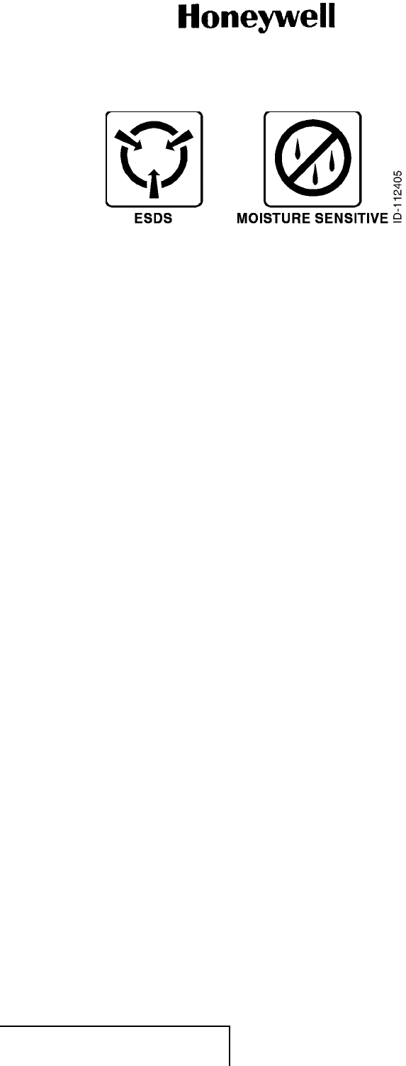
(4) The symbols in Figure 1 (GRAPHIC 23-15-30-99B-801-A01) show ESDS and moisture
sensitive devices.
EFFECTIVITY
ALL 23-15-30 Page7of70
5 Oct 2012
© Honeywell International Inc. Do not copy without express permission of Honeywell.
Interim DRAFT for FCC Approval Purposes
Do Not Use for Maintenance
10-Feb-2013
ABBREVIATED COMPONENT MAINTENANCE MANUAL
1458-A-1101 / 1458-A-1300
Figure 1. (Sheet 1 of 1) Symbols (GRAPHIC 23-15-30-99B-801-A01)
D. Units of Measure (Subtask 23-15-30-99F-004-A01)
(1) Measurements, weights, temperatures, dimensions, and other values are expressed in the
USMS followed by the appropriate SI metric units in parentheses. Some standard tools or
parts such as drills, taps, bolts, nuts, etc. do not have an equivalent.
E. Illustration (Subtask 23-15-30-99F-005-A01)
(1) Supplemental illustrations use a suffix number to the basic figure number. For example, if
Figure 501-5 is used, it signifies that it is an illustration of the item identified by index number 5
in Figure 501.
(2) Illustrations with no specific designation are applicable to all units.
F. Application of Maintenance Task Oriented Support System (MTOSS) (Subtask 23-15-30-
99F-006-A01)
(1) In accordance with the ATA Specification 2200, this publication uses a Maintenance Task
Numbering System which make the maintenance procedures in this manual compatible with
an automated shop environment.
(2) The system uses standard and unique number combinations to identify maintenance tasks
and subtasks.
(3) The MTOSS structure is the logical approach to organizing maintenance tasks and subtasks.
The MTOSS numbering system includes the ATA Chapter-Section-Subject number as well as a
function code and unique identifiers. The purpose of incorporating the MTOSS numbering
system is to provide a means for the automated sorting, retrieval, and management of
digitized data.
(4) Section and Sub-section Numbering System
(a) All procedures in this publication have TASK and SUBTASK numbers at key data retrieval
points. The numbers provide the following:
• Identification of the hardware (part or parts) primary to the TASK
• Identification of the maintenance function applied to the part or parts
• A unique identifier for a set of instructions (known as TASK or SUBTASK)
• Identification of alternate methods and configuration differences that change the
procedure applied to the TASK
• Identification of airline changes to a TASK or SUBTASK.
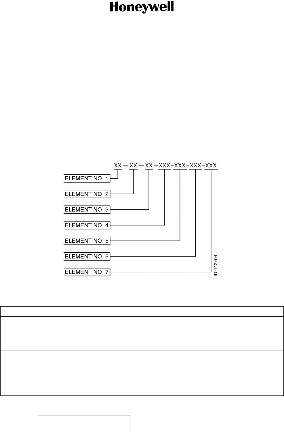
(5) Components of Task and Subtask Number
(a) The numbering system is an expansion of the ATA three-element numbering system. The
number has seven elements. The first five elements are necessary for each TASK or
SUBTASK. The sixth and seventh elements are applied only when necessary. Refer to
Figure 2 (GRAPHIC 23-15-30-99B-802-A01).
EFFECTIVITY
ALL 23-15-30 Page 8 of 70
5 Oct 2012
© Honeywell International Inc. Do not copy without express permission of Honeywell.
Interim DRAFT for FCC Approval Purposes
Do Not Use for Maintenance
10-Feb-2013
ABBREVIATED COMPONENT MAINTENANCE MANUAL
1458-A-1101 / 1458-A-1300
(b) Elements 1, 2, and 3 identify the ATA Chapter-Section-Subject number of the page block.
(c) Element 4 defines the maintenance function being performed. This element is a three
position element. The third position is zero filled when further definition is not required. If
required, the manufacturer will use the numbers 1 thru 9 or letters A thru Z, excluding the
letters I and O. Refer to Table 3.
(d) Element 5 provides a unique identification for each TASK or SUBTASK number which is
similarly numbered through the first four elements.
• TASKS are numbered from 801 thru 999
• SUBTASKS are numbered from 001 thru 800.
(e) Element 6 is a three position alphanumeric element used for identification of differences
in configurations, methods or techniques, variations of standard practice applications, etc.
(f) Element 7 provides coding of those tasks or subtasks that have been changed by the
customer (e.g., those tasks or subtasks accomplished by an outside repair source).
Figure 2. (Sheet 1 of 1) MTOSS Code Positions (GRAPHIC 23-15-30-99B-802-A01)
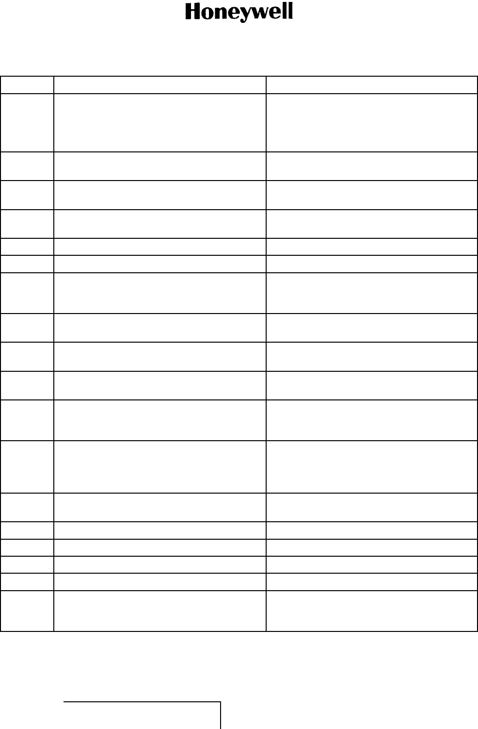
Table 3. MTOSS Function Code Definitions
Code Function Definition
000 REMOVAL AND DISASSEMBLY
010 Removal Removal of the engine/component from a
workstand, transport dolly, test stand, etc., or
aircraft.
020 Remove Modular Sections This is the first echelon of disassembly which
consists of sectionalization of the unit/engine
into primary modular sections. Modular
sections are identified by the third element
of the ATA number when removed from the
unit/engine.
EFFECTIVITY
ALL 23-15-30 Page9of70
5 Oct 2012
© Honeywell International Inc. Do not copy without express permission of Honeywell.
Interim DRAFT for FCC Approval Purposes
Do Not Use for Maintenance
10-Feb-2013

ABBREVIATED COMPONENT MAINTENANCE MANUAL
1458-A-1101 / 1458-A-1300
Code Function Definition
030 Disassemble Modular Sections This is the second echelon of disassembly
which consists of disassembly of the modular
sections into subassemblies after removal from
the unit/engine. Modular section designations
appear in the second element of the ATA
number for this echelon of disassembly.
040 Disassemble Subassemblies This is the third echelon of engine
disassembly which consists of disassembly
of subassemblies to the piece part level.
The subassemblies are identified by the third
element of the ATA number.
050 Remove Accessory/Power Plant Components This consists of removing individual
accessory/power plant components from either
installed or uninstalled engines.
060 Disassemble Accessory This involves disassembly of accessories
/components into subassemblies.
070 Disassemble Accessory Subassembly This involves disassembly of accessories
/components subassemblies into piece parts.
080 Remove Test Equipment This consists of removing equipment and
instrumentation after accessory/component
test.
090 Disassemble Support Equipment This consists of disassembly of support
equipment required to maintain said support
equipment.
100 CLEANING
110 Chemical Removal of surface deposits from a part by
use of a chemical cleaning agent. After being
dissolved, the deposit is washed or rinsed away
after a soaking period. Also includes chemical
power flushing.
120 Abrasive Removal of surface deposits from a part by wet
or dry particle impingement.
130 Ultrasonic Removal of surface deposits and entrapped
material by use of high frequency sound waves
to produce cavitation at the surface of the
part. Cleaning is performed in a liquid bath
that transmits the sound energy and keeps the
removed material in suspension.
140 Mechanical Removal of surface deposits from a part by use
of a brush, felt bob, sandpaper, or other hand
or mechanical action.
EFFECTIVITY
ALL 23-15-30 Page 10 of 70
5 Oct 2012
© Honeywell International Inc. Do not copy without express permission of Honeywell.
Interim DRAFT for FCC Approval Purposes
Do Not Use for Maintenance
10-Feb-2013

ABBREVIATED COMPONENT MAINTENANCE MANUAL
1458-A-1101 / 1458-A-1300
Code Function Definition
150 Unassigned
160 MiscellaneousRemoval of deposits from parts with
compressed air, miscellaneous hand cleaning,
and various combinations of cleaning
procedures.
170 Foam/Water Wash Removal or post emulsified fluorescent
penetrant via an agitated water wash,
automatic spray rinse, or an aqueous remover
aeratedtoproduceafoam.
180 Testing of Solutions Test used to assist in identifying certain
materials by electro-mechanically determining
the presence or absence of known constituents.
190 Unassigned
200 INSPECTION
210 Check Athoroughvisual examination of components,
accessories, subsystems, and piece parts
to detect structural failure, deterioration or
damage: and to determine the need for
corrective action. For example: exterior
surfaces, electronic circuit cards, gears, control
systems, linkages, accessories, components,
tubing, wiring and connections, safety wiring,
fasteners, clamps, etc., are inspected to verify
proper condition and acceptability for continued
service.
220 Visual/Dimensional A comparison of the dimensions and material
conditions of parts, subassemblies, and
assemblies with the specifications contained
in technical manuals and/or blueprints, to
detect deviations from established standard
and limits and determine the acceptability for
continued service, repair, or need to discard
the item. A visual/dimensional function code
is also required to verify that proper corrective
maintenance has been accomplished.
Although some of these tasks may not require
measurements, a complete spectrum of
tasks/sub tasks requires a variety of measuring
equipment to determine runout, concentricity,
flatness, parallelism, hardness, thickness,
clarity, dimensions, etc.
230 Penetrant Fluorescent penetrant inspection to detect
surface cracks.
EFFECTIVITY
ALL 23-15-30 Page 11 of 70
5 Oct 2012
© Honeywell International Inc. Do not copy without express permission of Honeywell.
Interim DRAFT for FCC Approval Purposes
Do Not Use for Maintenance
10-Feb-2013

ABBREVIATED COMPONENT MAINTENANCE MANUAL
1458-A-1101 / 1458-A-1300
Code Function Definition
240 Magnetic Magnetic particle inspection to detect surface
cracks in magnetic materials.
250 Eddy Current Inspection for subsurface cracks, porosity,
inclusions, or other nonhomogeneous
material structure by use of high frequency
electromagnetic wave equipment. Parts are
scanned and compared to similar parts or test
specimens having known material defects.
260 X-Ray Inspection for subsurface cracks, porosity,
inclusions, or other nonhomogeneous material
structure by use of x-ray techniques.
270 Ultrasonic Inspection for subsurface cracks, porosity,
inclusions, or other nonhomogeneous material
structure by use of contact pulse echo
ultrasonic techniques.
280 Special Any special inspection to determine the
integrity of a part for continued operation
In-Service or qualitative analysis.
290 Unassigned
300 REPAIR
310 Welding and Brazing The joining of pieces by welding (fusion,
resistance, spot, electron beam, plasma arc),
brazing (furnace, torch, induction), or soldering.
This category includes hard facing.
320 Machining The process of obtaining a desired shape or
finish by grinding, turning, boring, reaming,
broaching, milling, drilling, lapping, honing,
sizing, polishing, buffing, cutting, forming,
stamping, blanking, etc.
330 Stripping and Plating Removing or applying a metallic coating on a
surface by mechanical, chemical, or electrical
means. Plating of chromium, cadmium, tin,
etc., to build up the size of a part or provide
surface protection. Includes masking or waxing
prior to the process.
340 Plasma and Flame Spraying The application of a protective coating to a
part by feeding a powder into an ionized gas
stream. Flame spraying uses a fuel oxygen
flame to melt and propel metal onto parts to
build up the size or provide surface protection.
EFFECTIVITY
ALL 23-15-30 Page 12 of 70
5 Oct 2012
© Honeywell International Inc. Do not copy without express permission of Honeywell.
Interim DRAFT for FCC Approval Purposes
Do Not Use for Maintenance
10-Feb-2013

ABBREVIATED COMPONENT MAINTENANCE MANUAL
1458-A-1101 / 1458-A-1300
Code Function Definition
350 Miscellaneous Repairs Repairing parts by hand (cutting, drilling,
polishing, grinding, lapping, riveting, blending,
routing, fitting, burring, planishing, sanding,
sawing, recambering, drilling, tapping,
heating, chilling) and including miscellaneous
disassembly and assembly required.
360 Bonding and Molding/Sealing Joining and curing of parts with an adhesive or
fusible material (including silicone, fiberglass,
glues).
370 Heat Treating Controlled heating and cooling of a material to
obtain the desired physical property (includes
annealing, tempering, quenching, stress
relieving, solution heat treat, etc.).
380 Surface Treating Treating the surface of a part by painting,
varnishing, aluminizing, Teflon coating, zinc
chromate priming, tumble finishing, shot
peening, etc. Baking and masking processes
are included.
390 Machine Riveting and Flaring Joining of parts by riveting and flaring the rivet.
400 INSTALLATION AND ASSEMBLY
410 Install Installation of the unit/engine onto a workstand,
transportdolly,teststand,oraircraft.
420 Install Modular Sections The third echelon of assembly consisting of
assembly of the modular assemblies into a
complete unit/engine assembly. The modular
sections are identified by the third element of
the ATA number.
430 Assemble Modular Sections The second echelon of assembly consisting
of assembling subassemblies into modular
sections. The modular section is identified by
the second element of the ATA number.
440 Assemble Subassemblies The first echelon of assembly consisting of
assembling piece parts into subassemblies.
The subassemblies are identified by the third
element of the ATA number.
450 Install/Close Items Removed/Opened for
Access
Installation or closing of access plates, closing
of ports, installation of components, tubing
or any item which was removed or opened in
order to provide access to perform the task.
EFFECTIVITY
ALL 23-15-30 Page 13 of 70
5 Oct 2012
© Honeywell International Inc. Do not copy without express permission of Honeywell.
Interim DRAFT for FCC Approval Purposes
Do Not Use for Maintenance
10-Feb-2013
ABBREVIATED COMPONENT MAINTENANCE MANUAL
1458-A-1101 / 1458-A-1300
Code Function Definition
460 Assemble Accessory Assemble accessory components.
470 Assemble Accessory Subassembly Assembly of accessory subassembly
components.
480 Install Test Equipment Install equipment and instrumentation required
for accessory component test.
490 Assemble Support Equipment Any assembly required to maintain support
equipment.
500 MATERIAL HANDLING
510 Shipping Themovementofanypart,subassembly,
assembly, or component from the time it is
packaged until it reaches its destination.
520 ReceivingThe receipt activity for any incoming part,
subassembly, assembly, or component.
530 Packing Installing parts, subassemblies, assemblies, or
components into shipping containers.
540 Unpacking Removing parts, subassemblies, assemblies,
or components from shipping containers.
550 Storage Safekeeping of parts, subassemblies,
assemblies, or components until required for
use.
560 Marshaling/Positioning Marshaling is collection of parts,
subassemblies, and accessories prior to
release for assembly. Positioning is movement
from one fixed state to another.
570 Engine Ferry/Pod Maintenance Necessary preparations before and after
transporting an engine by aircraft ferry method.
580 Unassigned
590 Unassigned
600 SERVICING/PRESERVING/LUBRICATING
610 Servicing Action required to sustain a unit or system in
proper operating status including priming with
applicable fluids prior to use.
EFFECTIVITY
ALL 23-15-30 Page 14 of 70
5 Oct 2012
© Honeywell International Inc. Do not copy without express permission of Honeywell.
Interim DRAFT for FCC Approval Purposes
Do Not Use for Maintenance
10-Feb-2013
ABBREVIATED COMPONENT MAINTENANCE MANUAL
1458-A-1101 / 1458-A-1300
Code Function Definition
620 Preserving Preparation of a unit, part, assembly, etc.,
for safekeeping from decomposition or
deterioration. Includes preparation for storage
(applying a preservative layer, desiccants, etc.).
630 DepreservingRemoving preservatives, desiccants, etc., from
a unit, part, assembly, etc., prior to installation
or operation.
640 Lubricating Applying oil, grease, dry film, or silicon
lubricants on moving parts to reduce friction
or cool the item.
650 Unassigned
660 Unassigned
670 Unassigned
680 Unassigned
690 Unassigned
700 TESTING/CHECKING
710 Oil Flow Measuring the flow of oil through components
or compartments under specific conditions.
720 Air Flow Measuring the flow of air through components
or compartments under specific conditions.
730 Fuel Flow Function checks and flow measurements
through the part or system being tested.
740 Water Flow Function checks and flow measurements
through the part or system being tested.
750 Electrical/Return to Service Functional tests (manual or ATE) of the system
or component as well as measurement of
electrical or electronic parameters designed to
determine whether the item can be returned to
service. May include fault isolation procedures
for components that require close correlation
between test results and fault indications.
760 Engine Operation of an engine to establish systems
function or operation under specific conditions
to measure performance.
770 Accessory/Bite Te s t ing of an accessory to ensure proper
operation or function.
780 Pressure Check Testing to establish the ability of a normally
pressurized component or system to operate
properly.
EFFECTIVITY
ALL 23-15-30 Page 15 of 70
5 Oct 2012
© Honeywell International Inc. Do not copy without express permission of Honeywell.
Interim DRAFT for FCC Approval Purposes
Do Not Use for Maintenance
10-Feb-2013

ABBREVIATED COMPONENT MAINTENANCE MANUAL
1458-A-1101 / 1458-A-1300
Code Function Definition
790 Leak Check Determine the ability of a component or system
to operate without leaking.
800 MISCELLANEOUS
810 Fault Isolation Operation of an engine at constant thrust level
or identical Engine Pressure Ratio (EPR) to
locate the prime suspect deficient system:
operating an improperly functioning system or
component to locate the cause; or performing
a series of checks to isolate a failed part or
component.
820 Adjusting/Aligning/Calibrating Makingaphy
sical correction to ensure
proper placement or operation of a system or
component.
830 Rigging Hooking-up, arranging, or adjusting a
component or accessory linkage for proper
operation.
840 Service Bulletin Incorporation Performing the work specified in the
service bulletin. Provides for identification
of modification tasks at the task level with
subtasks recognizing any functional changes
(chemical, visual/dimensional, cleaning,
machining, etc.) necessary to incorporate the
service bulletin.
850 PN Change/Re-identification Change of PN, application of PN by transfer,
engrave repair number, etc.
860 Unassigned
870 Description and Operation Electrical and mechanical description of the
unit or component. Includes leading particulars,
descriptions, limitations, specifications, and
theory of operation.
880 Approved Vendor Processes Includes processes that may be proprietary
and controlled by a particular manufacturer, or
by nonproprietary and approved for application
by conforming vendors.
890 Airline Maintenance Program (Customer Use)
900 Unassigned
910 Special Equipment Maintenance Identification of tasks to maintain special
support equipment.
920 Standard Equipment Maintenance Identification of tasks to maintain standard
support equipment.
EFFECTIVITY
ALL 23-15-30 Page 16 of 70
5 Oct 2012
© Honeywell International Inc. Do not copy without express permission of Honeywell.
Interim DRAFT for FCC Approval Purposes
Do Not Use for Maintenance
10-Feb-2013

ABBREVIATED COMPONENT MAINTENANCE MANUAL
1458-A-1101 / 1458-A-1300
Code Function Definition
930 Tool Fabrication Includes fabricating any tool for which
procedures to use are included in the manual.
940 Special Tools, Equip, and Consumables Listing Listing of all special tools, standard equipment,
special equipment, and consumables required
to perform maintenance on the unit or
component.
94A Consumables
94B Special Tools/Non Std Tools
94C Fixtures/Test Equipment
94D Standard Tools
950 Illustrated Parts List (Detailed Parts List) Section of IPL/IPC that contains parts
description and identification in top-down break
down sequence.
960 Illustrated Parts List (Equipment Designation
Index)
Section of IPL/IPC that contains equipment
designators cross-referenced to detailed parts
list.
970 Illustrated Parts List (Numerical Index) Section of IPL/IPC that contains an
alphanumeric listing of all parts in the unit
cross-referenced to the detailed parts list.
980 Illustrated Parts List (Alternate Vendor Index) Optional section of IPL/IPC that contains an
alphanumeric listing of all parts in the unit that
have more than one vendor source.
990 Illustrations, Tables, Front Matter, Etc.
99A Ta b l e s
99B Illustrations
99C Front Matter Pageblock (TASK Level MTOSS)
Front Matter Task (Collection of Subtask
MTOSS)
99D Access
99E References
99F General/Introduction
2. Customer Support (TASK 23-15-30-99F-802-A01)
A. Honeywell Aerospace Online Technical Publications Website (Subtask 23-15-30-99F-007-A01)
(1) Go to the Honeywell Online Technical Publications Website at http://www.myaerospace.com
• To download or see publications online
• To order a publication
• To tell Honeywell of a possible data error in a publication.
EFFECTIVITY
ALL 23-15-30 Page 17 of 70
5 Oct 2012
© Honeywell International Inc. Do not copy without express permission of Honeywell.
Interim DRAFT for FCC Approval Purposes
Do Not Use for Maintenance
10-Feb-2013

ABBREVIATED COMPONENT MAINTENANCE MANUAL
1458-A-1101 / 1458-A-1300
B. Global Customer Care Center (Subtask 23-15-30-99F-008-A01)
(1) If you do not have access to the Honeywell Technical Publications Website, or if you need to
speak to personnel about non-Technical Publication matters, the Honeywell Aerospace Global
Customer Care Center gives 24/7 customer service to Air Transport & Regional, Business &
General Aviation, and Defense & Space customers around the globe.
• Telephone: 800-601-3099 (Toll Free U.S.A./Canada)
• Telephone: 602-365-3099 (International)
• Telephone: 00-800-601-30999 (EMEA Toll Free)
• Telephone: 420-234-625-500 (EMEA Direct).
3. References (TASK 23-15-30-99F-803-A01)
A. Honeywell/Vendor Publications (Subtask 23-15-30-99F-009-A01)
(1) Not applicable.
B. Other Publications (Subtask 23-15-30-99F-010-A01)
(1) These publications are standard references:
• The United States GPO Style Manual 2000 (available at http://www.gpoaccess.gov
/stylemanual/browse.html)
• IEEE Std 260, Standard Letter Symbols for Units of Measurement (available from the
American National Standards Institute, New York, NY)
• ASME Y14.38, Abbreviations for Use on Drawings and in Text (available from the American
National Standards Institute, New York, NY)
• H4/H8 CAGE Codes (available at http://www.logisticsinformationservice.dla.mil)
• IEEE 315/ANSI Y32.2, Graphic Symbols for Electrical and Electronics Diagrams (available
from the American National Standards Institute, New York, NY)
• TSO-C132 Geosynchronous Aeronautical Mobile Satellite Services Earth Station Equipment
• ARINC 781 Mark 3 Aviation Satellite Communications System
• ARINC 758 Communications Management Unit Mark 2
• DO-160E Environmental Conditions and Test Procedures for Airborne Equipment
• DO-178B Software Considerations in Airborne Systems and Equipment Certification
• DO-254 Design Assurance Guidance for Airborne Electronic Hardware.
C. Certification and Approvals (Subtask 23-15-30-99F-011-A01)
(1) Installation of the A350 SDU and SCM system on an aircraft typically requires the approval
of the appropriate government air/radio authority (such as Transport Canada, the FAA, the
JAA, etc.). Honeywell highly recommends contacting the appropriate authorities early in the
system-planning phase to minimize approval/certification issues that could delay release
of the aircraft.
(2) The conditions and tests for TSO approval of this article are minimum performance standards.
Those installing this article, on or within a specific type or class of aircraft, must determine
that the aircraft installation conditions are within the TSO standards. TSO articles must have
different approval for installation in an aircraft. The article can be installed only according to 14
CFR part 43, or the applicable airworthiness requirements.
(3) Contact Honeywell for more information on certification and approval issues.
EFFECTIVITY
ALL 23-15-30 Page 18 of 70
5 Oct 2012
© Honeywell International Inc. Do not copy without express permission of Honeywell.
Interim DRAFT for FCC Approval Purposes
Do Not Use for Maintenance
10-Feb-2013

ABBREVIATED COMPONENT MAINTENANCE MANUAL
1458-A-1101 / 1458-A-1300
4. Acronyms and Abbreviations (TASK 23-15-30-99F-804-A01)
A. General (Subtask 23-15-30-99F-012-A01)
(1) The abbreviations are used in agreement with ASME Y14.38.
(2) Acronyms and non-standard abbreviations used in this publication are as follows:
List of Acronyms and Abbreviations
Term Full Term
AC alternating current
ACMM abbreviated component maintenance manual
ADIRU air data inertial reference unit
AFDX avionics full duplex switched ethernet
AMM aircraft maintenance manual
AMSS aeronautical mobile satellite services
AMU audio management unit
ANSI American National Standards Institute
AORE Atlantic Ocean Region-East
AORW Atlantic Ocean Region-West
ARINC Aeronautical Radio, Incorporated
ASME American Society of Mechanical Engineers
ATA Air Transport Association
ATE automated test equipment
BITE built-in test equipment
BP bottom plug
bps bits per second
C Celsius
CAGE commercial and government entity
CFR code of federal regulation
CMS central maintenance system
CRES corrosion resistant steel
DC direct current
DLCS data loading and configuration system
DLNA diplexer/low noise amplifier
EMEA Europe, the Middle East, and Africa
ESDS electrostatic discharge sensitive
EST Eastern Standard Time
F Fahrenheit
FAA Federal Aviation Administration
EFFECTIVITY
ALL 23-15-30 Page 19 of 70
5 Oct 2012
© Honeywell International Inc. Do not copy without express permission of Honeywell.
Interim DRAFT for FCC Approval Purposes
Do Not Use for Maintenance
10-Feb-2013

ABBREVIATED COMPONENT MAINTENANCE MANUAL
1458-A-1101 / 1458-A-1300
FWS flight warning system
GES ground earth station
GPO Government Printing Office
HGA high gain antenna
HMI human machine interface
HPA high power amplifier
hr hour
Hz Hertz
I/O input/output
ICA Instructions for Continued Airworthiness
ICAO International Civil Aviation Organization
IEC International Electrotechnical Commission
IEEE Institute of Electrical and Electronics Engineers
IM interactive mode
in-lb inch-pound
IOR Indian Ocean Region
IPC iIlustrated parts catalog
IPL illustrated parts list
ISDN integrated services digital network
JAA Joint Aviation Authority
kbps kilobits per second
kg kilogram
LED light emitting diode
LES land earth station
LGERS landing gear extension/retraction system
mA milliampere
MAX maximum
MCU modular concept unit
MEL minimum equipment list
MES mobile earth station
MHz megahertz
mm millimeter
MP middle plug
MPDS mobile packet data service
MTOSS maintenance task oriented support system
Nm newton meter
No. number
EFFECTIVITY
ALL 23-15-30 Page 20 of 70
5 Oct 2012
© Honeywell International Inc. Do not copy without express permission of Honeywell.
Interim DRAFT for FCC Approval Purposes
Do Not Use for Maintenance
10-Feb-2013

ABBREVIATED COMPONENT MAINTENANCE MANUAL
1458-A-1101 / 1458-A-1300
ORT owner requirements table
PA power amplifier
PN part number
POR Pacific Ocean Region
RF radio frequency
RMA return material authorization
RMP radio management panel
RMU radio management unit
RTCA Radio Technical Commission for Aeronautics
SATCOM satellite communications
SBB swift broadband
SCM satellite data unit configuration module
SDIMM system description, installation, and maintenance manual
SDU satellite data unit
SI International System of Units
SIS standalone identification system
SRU shop replaceable unit
STC supplemental type certificate
TP top plug
TSO technical standing order
U.S.A. United States of America
USIM universal subscriber identity module
USMS United States Measurement System
VAC volt, alternating current
VDC volt, direct current
5. Process Verification (TASK 23-15-30-99F-805-A01)
A. Verification Data (Subtask 23-15-30-99F-013-A01)
(1) Honeywell does a verification of these technical instructions by demonstration or by simulation
of the necessary procedures. Demonstration shows that the procedures were checked by the
use of the manual. Simulation shows that the applicable personnel looked at the procedure
in the manual and that the procedure is technically correct. The dates of verification for
this manual are given in Table 4.
EFFECTIVITY
ALL 23-15-30 Page 21 of 70
5 Oct 2012
© Honeywell International Inc. Do not copy without express permission of Honeywell.
Interim DRAFT for FCC Approval Purposes
Do Not Use for Maintenance
10-Feb-2013
ABBREVIATED COMPONENT MAINTENANCE MANUAL
1458-A-1101 / 1458-A-1300
Table 4. Verification Data
Section Method Date
Testing and Fault Isolation 1Demonstration 14 Nov 2012
NOTE:
1Only the TESTING portion of the TESTING AND FAULT ISOLATION section was done by demonstration.
DESCRIPTION AND OPERATION
1. Description (TASK 23-15-30-870-801-A01)
A. General (Subtask 23-15-30-870-001-A01)
(1) This section contains a description of the A350 SDU and SCM.
(2) The A350 SATCOM avionics products developed under this program complement Honeywell
SATCOMs existing range of SATCOM products. The Honeywell furnished A350 SATCOM
avionics, in concert with the amplifier and antenna subsystem, achieves all of the requirements
for providing AMSS by facilitating airborne satellite communications. These services
comprise Classic Aero-H+, Swift64 and SBB as described above provided by Inmarsat and
its designated service provider agencies.
(3) The A350 SATCOM avionics is an integral part of the complete L-band Inmarsat SATCOM
system and comprises of the following components:
• SDU PN 1458-A-1100
• SCM PN 1458-A-1300.
(4) Refer to Table 5 for the SDU leading particulars.
(5) Refer to Table 6 for the SCM leading particulars.
Table 5. SDU Leading Particulars
Characteristic Specification
Length 14.58 inches (370.3 mm)
Width 7.52 inches (191.0 mm)
Height 7.85 inches (199.4 mm)
Weight 18.08 pounds (8.2 kg)
Heating and cooling:
• Cooling air ARINC 600
•Flowrate 110.2 lb/hr (50 kg/hr), 104 F(40C) (MAX) air
• Pressure drop 0.2 ±0.12 inH2O(5±3mmH
2O)
Mounting information 6 MCU tray as per ARINC 600
Electrical interfaces:
• Power/Control interface ARINC 781
Power requirements:
EFFECTIVITY
ALL 23-15-30 Page 22 of 70
5 Oct 2012
© Honeywell International Inc. Do not copy without express permission of Honeywell.
Interim DRAFT for FCC Approval Purposes
Do Not Use for Maintenance
10-Feb-2013

ABBREVIATED COMPONENT MAINTENANCE MANUAL
1458-A-1101 / 1458-A-1300
Characteristic Specification
• Input voltage (AC) 96 to 122 VAC, 300 to 900 Hz
• Input voltage (DC) 18 to 32.3 VDC
Power consumption 300 mA if operated with an external FMPA
400 mA if operated as standalone
Table 6. SCM Leading Particulars
Characteristic Specification
Length 4.75 inches (120.7 mm)
Width 4.00 inches (101.6 mm)
Height 1.00 inch (25.4 mm)
Weight 0.66 pound (0.30 kg)
Mounting information 4 x 0.125 inch (3.18 mm) holes on 3.3 x 3.50 inches
(88.9 mm) spacing, per attachment 1-6 of ARINC
781
Electrical interfaces:
•P
ower/Control interface ARINC 781
Power requirements +12 volts ±5% (derived from SDU)
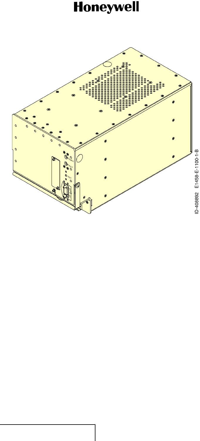
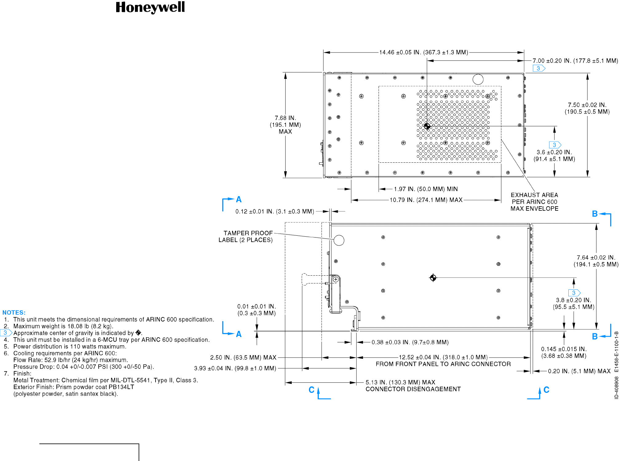
(6) Refer to Figure 3 (GRAPHIC 23-15-30-99B-803-A01) for the SDU and Figure 4 (GRAPHIC
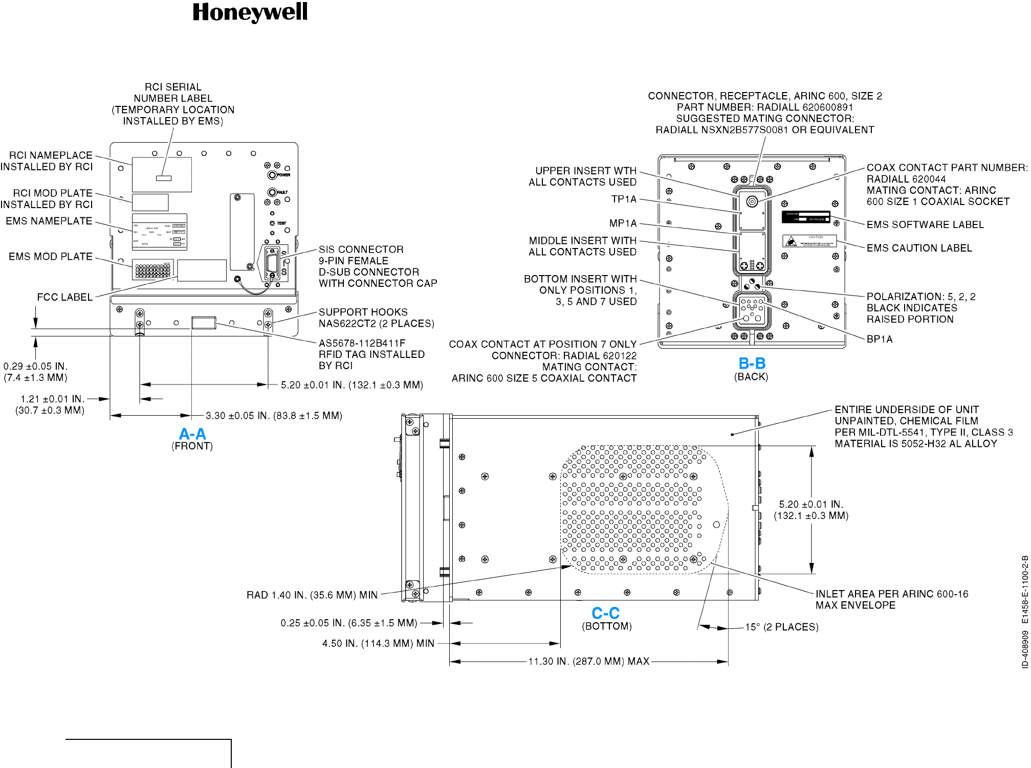
23-15-30-99B-804-A01) for detailed information on the physical characteristics of the SDU.
EFFECTIVITY
ALL 23-15-30 Page 23 of 70
5 Oct 2012
© Honeywell International Inc. Do not copy without express permission of Honeywell.
Interim DRAFT for FCC Approval Purposes
Do Not Use for Maintenance
10-Feb-2013
ABBREVIATED COMPONENT MAINTENANCE MANUAL
1458-A-1101 / 1458-A-1300
Figure 3. (Sheet 1 of 1) SDU (GRAPHIC 23-15-30-99B-803-A01)
EFFECTIVITY
ALL 23-15-30 Page 24 of 70
5 Oct 2012
© Honeywell International Inc. Do not copy without express permission of Honeywell.
Interim DRAFT for FCC Approval Purposes
Do Not Use for Maintenance
10-Feb-2013
ABBREVIATED COMPONENT MAINTENANCE MANUAL
1458-A-1101 / 1458-A-1300
Figure 4. (Sheet 1 of 2) SDU Outline and Installation Drawing (GRAPHIC 23-15-30-99B-804-A01)
EFFECTIVITY
ALL 23-15-30 Pages 25/26 of 70
5 Oct 2012
© Honeywell International Inc. Do not copy without express permission of Honeywell.
Interim DRAFT for FCC Approval Purposes
Do Not Use for Maintenance
10-Feb-2013
Interim DRAFT for FCC Approval Purposes
Do Not Use for Maintenance
10-Feb-2013
ABBREVIATED COMPONENT MAINTENANCE MANUAL
1458-A-1101 / 1458-A-1300
Figure 4. (Sheet 2 of 2) SDU Outline and Installation Drawing (GRAPHIC 23-15-30-99B-804-A01)
EFFECTIVITY
ALL 23-15-30 Pages 27/28 of 70
5 Oct 2012
© Honeywell International Inc. Do not copy without express permission of Honeywell.
Interim DRAFT for FCC Approval Purposes
Do Not Use for Maintenance
10-Feb-2013
Interim DRAFT for FCC Approval Purposes
Do Not Use for Maintenance
10-Feb-2013
ABBREVIATED COMPONENT MAINTENANCE MANUAL
1458-A-1101 / 1458-A-1300
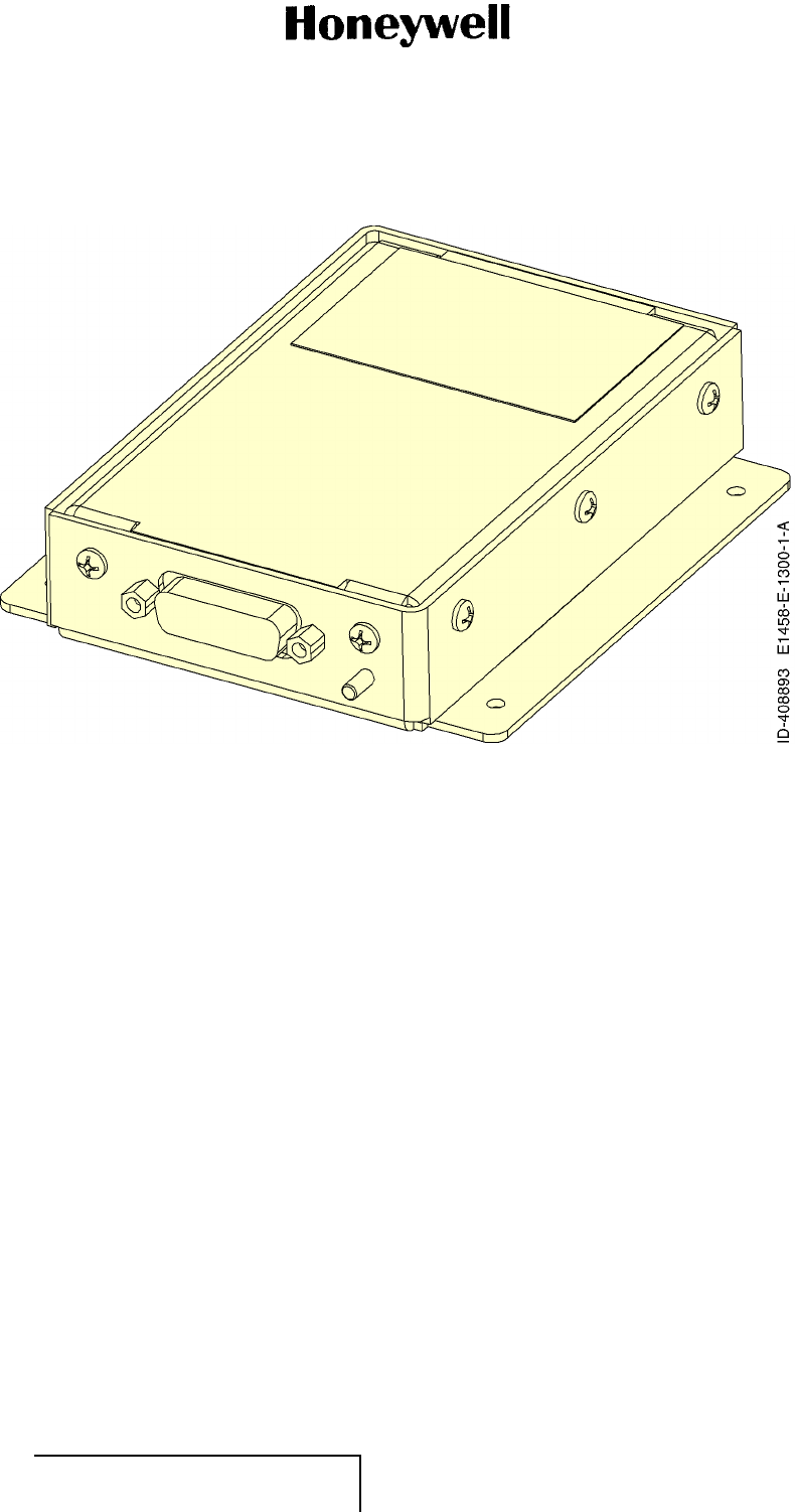
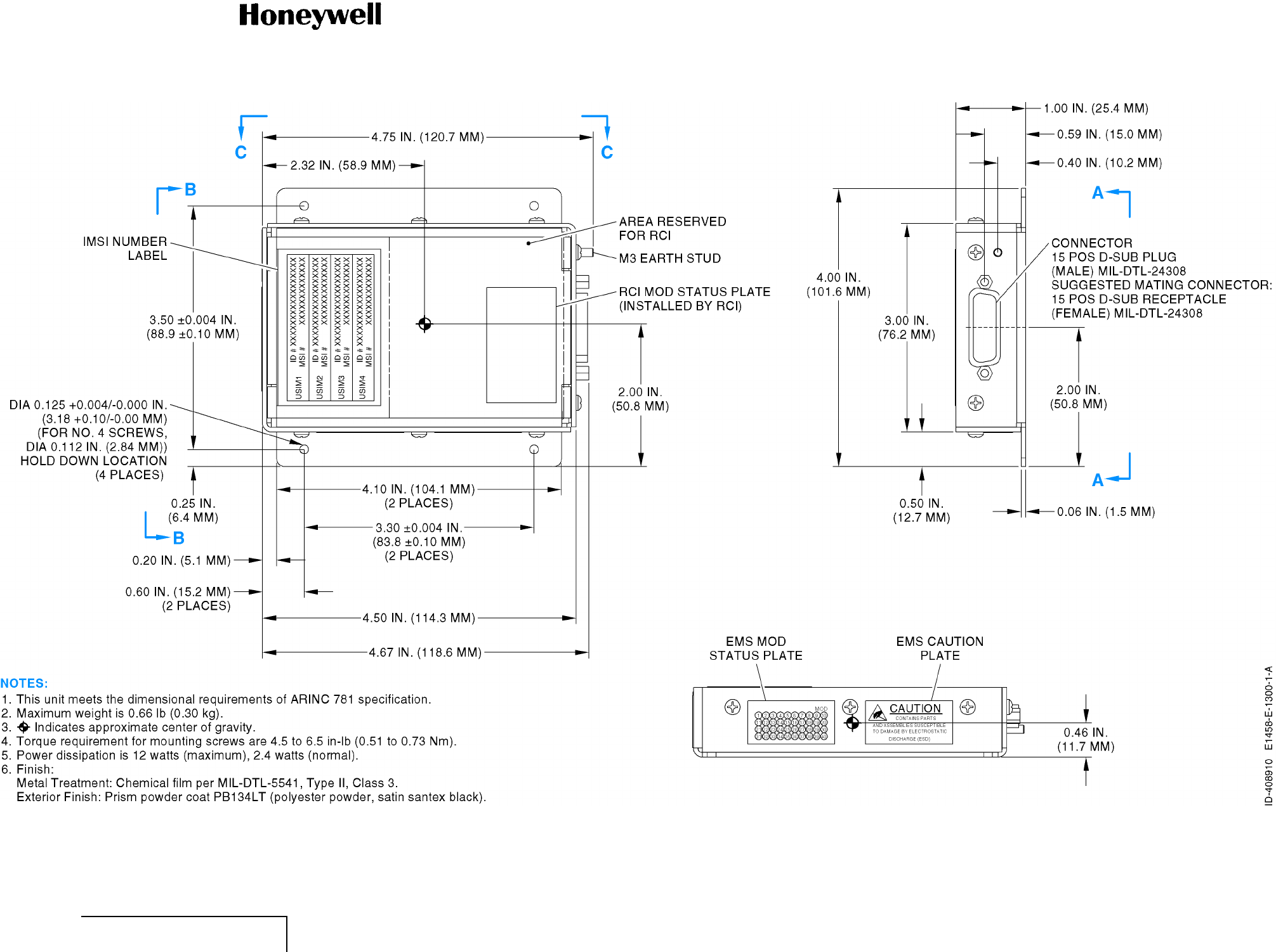
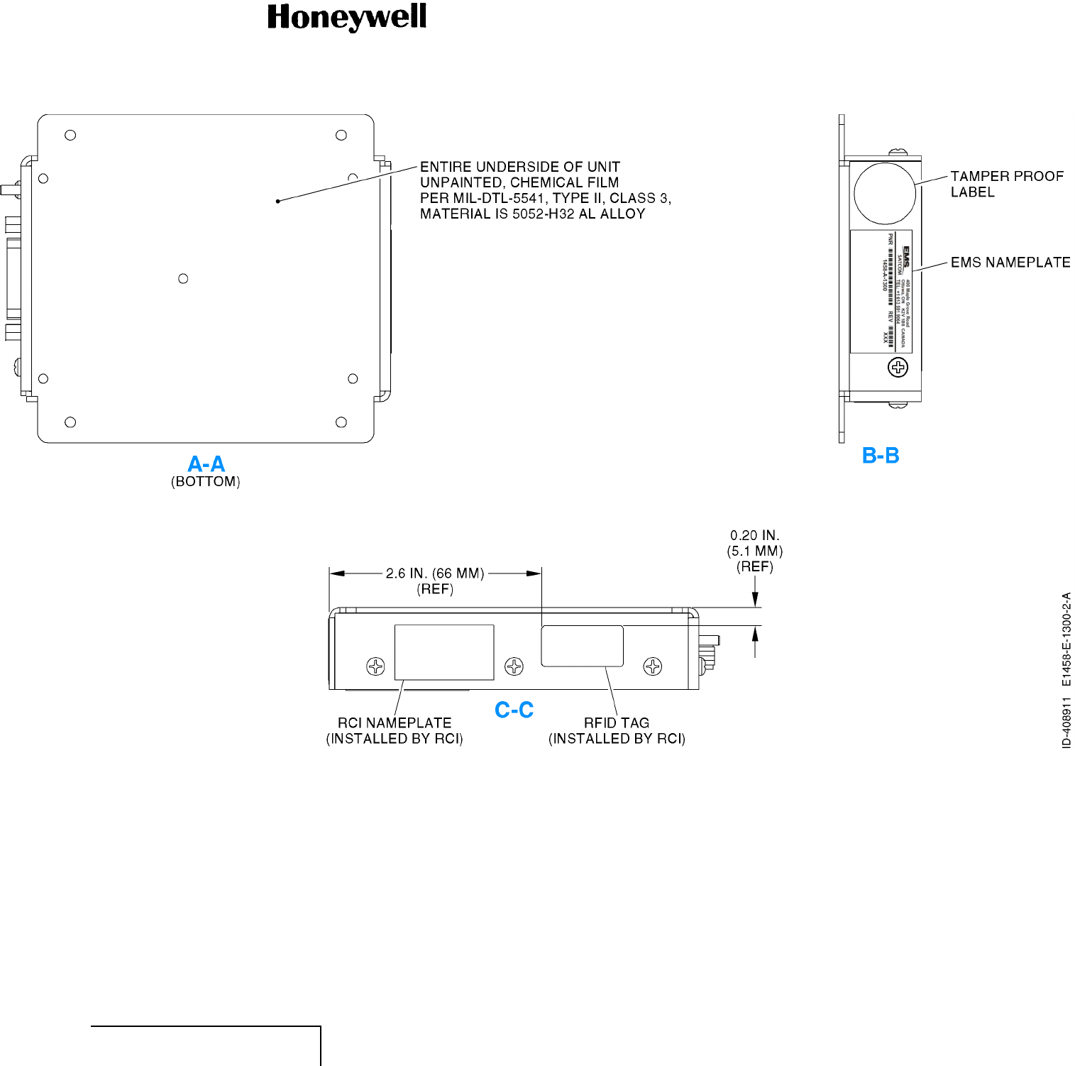
(7) Refer to Figure 5 (GRAPHIC 23-15-30-99B-805-A01) for the SCM and Figure 6 (GRAPHIC
23-15-30-99B-806-A01) for a detailed information on the physical characteristics of the SCM.
Figure 5. (Sheet 1 of 1) SCM (GRAPHIC 23-15-30-99B-805-A01)
EFFECTIVITY
ALL 23-15-30 Page 29 of 70
5 Oct 2012
© Honeywell International Inc. Do not copy without express permission of Honeywell.
Interim DRAFT for FCC Approval Purposes
Do Not Use for Maintenance
10-Feb-2013

ABBREVIATED COMPONENT MAINTENANCE MANUAL
1458-A-1101 / 1458-A-1300
Blank Page
EFFECTIVITY
ALL 23-15-30 Page 30 of 70
5 Oct 2012
© Honeywell International Inc. Do not copy without express permission of Honeywell.
Interim DRAFT for FCC Approval Purposes
Do Not Use for Maintenance
10-Feb-2013
ABBREVIATED COMPONENT MAINTENANCE MANUAL
1458-A-1101 / 1458-A-1300
Figure 6. (Sheet 1 of 2) SCM Outline and Installation Drawing (GRAPHIC 23-15-30-99B-806-A01)
EFFECTIVITY
ALL 23-15-30 Pages 31/32 of 70
5 Oct 2012
© Honeywell International Inc. Do not copy without express permission of Honeywell.
Interim DRAFT for FCC Approval Purposes
Do Not Use for Maintenance
10-Feb-2013
Interim DRAFT for FCC Approval Purposes
Do Not Use for Maintenance
10-Feb-2013
ABBREVIATED COMPONENT MAINTENANCE MANUAL
1458-A-1101 / 1458-A-1300
Figure 6. (Sheet 2 of 2) SCM Outline and Installation Drawing (GRAPHIC 23-15-30-99B-806-A01)
EFFECTIVITY
ALL 23-15-30 Pages 33/34 of 70
5 Oct 2012
© Honeywell International Inc. Do not copy without express permission of Honeywell.
Interim DRAFT for FCC Approval Purposes
Do Not Use for Maintenance
10-Feb-2013
Interim DRAFT for FCC Approval Purposes
Do Not Use for Maintenance
10-Feb-2013

ABBREVIATED COMPONENT MAINTENANCE MANUAL
1458-A-1101 / 1458-A-1300
(8) Table 7 lists the equipment covered by this manual.
Table 7. Equipment Description
Equipment PN Description/Notes
SDU 1458-A-1101 The central communications processing and control unit.
SCM 1458-A-1300 Stores installation configuration, ORT, ICAO, and USIM information.
B. Job Setup Data (Subtask 23-15-30-99C-001-A01)
(1) The list that follows identifies Honeywell publications that are related to this section:
• Not applicable.
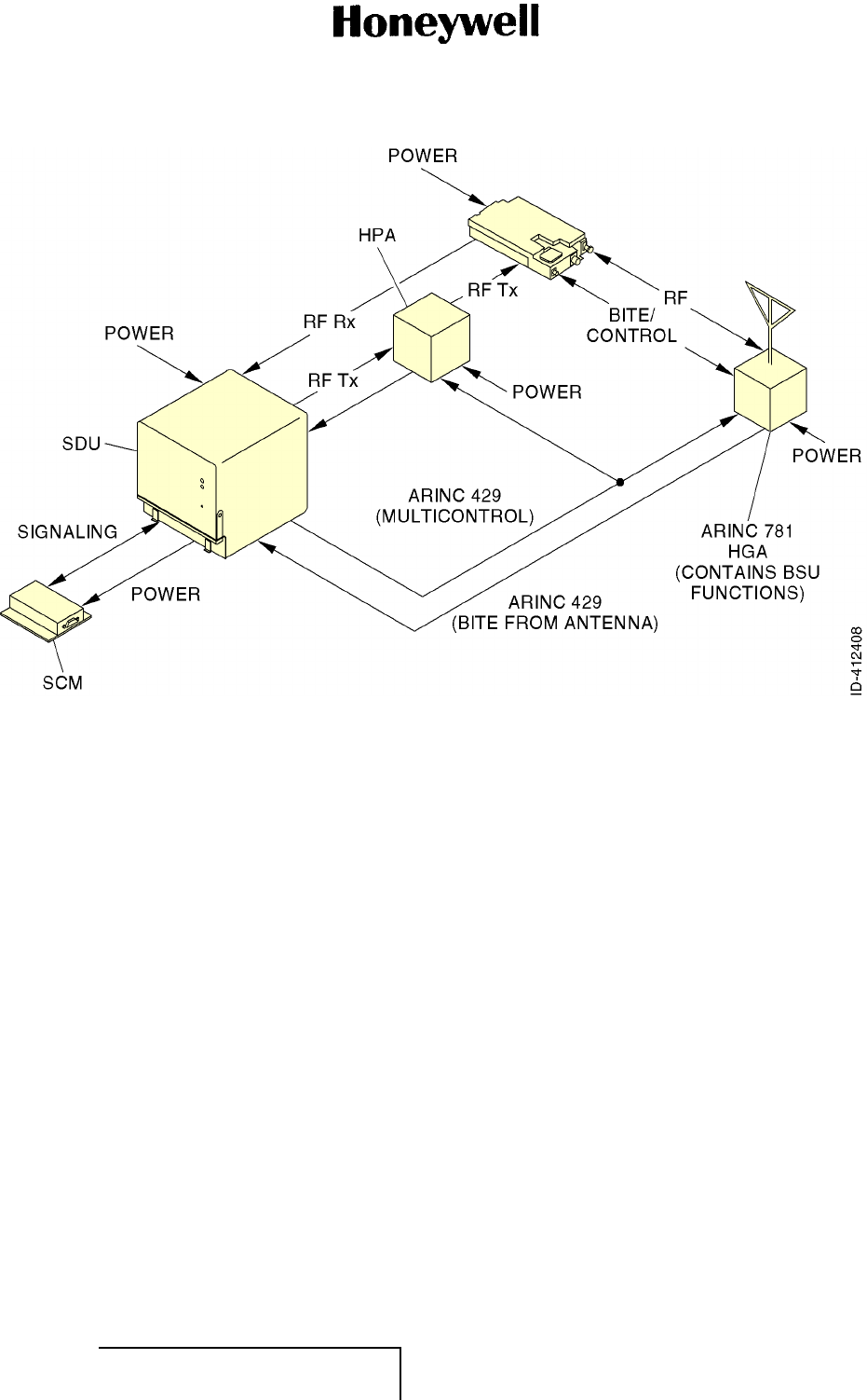
C. A350 SDU and SCM (Subtask 23-15-30-870-002-A01)
(1) SDU
(a) The SDU is the central communications processing and control unit, largely determining
the functionality of the complete SATCOM system. The signal-in-space parameters are
determined by the SDU in relation to modulation/demodulation, error correction, coding,
interleaving and data rates associated with the communication channel(s). The SDU
contains circuits for conversion of digital and/or analog inputs/outputs to/from RF, and
typically contains a PA module. The SDU interfaces at L-band with the HPA and DLNA
and also controls the antenna.
(b)The SDU is capable of sending and receiving various data rates. The rate is dynamically
selected by the individual applications and by pragmatic assessment of current operating
conditions.
(2) SCM
(a) The SCM is an external peripheral of the SDU and provides a dedicated interface to the
SDU. It stores aircraft specific installation configuration, ORT configuration, and ICAO
identities. The SCM also contains four USIM that store subscriber information for the
SBB network.
(b) By storing configuration information independent of the SDU, the SCM facilitates
efficient SDU replacement. A new SDU that replaces a faulty SDU does not require any
configuration. All configuration information is obtained from the SCM.
(3) Refer to Figure 7 (GRAPHIC 23-15-30-99B-807-A01) for the A350 SATCOM Avionics System.
EFFECTIVITY
ALL 23-15-30 Page 35 of 70
5 Oct 2012
© Honeywell International Inc. Do not copy without express permission of Honeywell.
Interim DRAFT for FCC Approval Purposes
Do Not Use for Maintenance
10-Feb-2013
ABBREVIATED COMPONENT MAINTENANCE MANUAL
1458-A-1101 / 1458-A-1300
Figure 7. (Sheet 1 of 1) A350 SATCOM Avionics System (GRAPHIC 23-15-30-99B-807-A01)
D. Purpose of the Equipment (Subtask 23-15-30-870-003-A01)
(1) The A350 SATCOM Avionics System enables airborne satellite communications, including the
following services:
• AERO or “Classic” AERO - This service provides packet data services at 600, 1200, or
10500 bps over the PRT channel combination and half-rate circuit switched voice or data
service over the C channel.
• Swift64 - This service provides circuit switched 64 kbps, and 56 kbps mobile ISDN. In
addition, it provides packet switched MPDS up to 64 kbps.
• SBB - This service will give broadband circuit and packet switched services with data
rates of 128 kbps and higher per channel.
(2) The following interfaces are provided for the above defined services:
(a) AMU (x2) - Provides voice and voice control discretes:
• 4 wire port (x2) - 4 wire voice communication system used for AERO voice service
from the cockpit
• Call and Mic ON discretes.
(b) Ethernet Port (x2) - one used at any one time (under ORT control) for packet data
services access
(c) RMP (x3) - The RMP is installed in the cockpit and interfaces directly to the A350 SDU
over a standard ARINC 429 interface. The RMP implements the HMI necessary to control
radio and satellite communication equipment. The RMP enables user to:
EFFECTIVITY
ALL 23-15-30 Page 36 of 70
5 Oct 2012
© Honeywell International Inc. Do not copy without express permission of Honeywell.
Interim DRAFT for FCC Approval Purposes
Do Not Use for Maintenance
10-Feb-2013

ABBREVIATED COMPONENT MAINTENANCE MANUAL
1458-A-1101 / 1458-A-1300
• Place calls manually or from a directory
• Accept, reject, preempt incoming calls
• View and change SATCOM settings and options
• Select auto login or control logon with manual logon and logoff options
• Control cabin communications (cabin calls enable/disable).
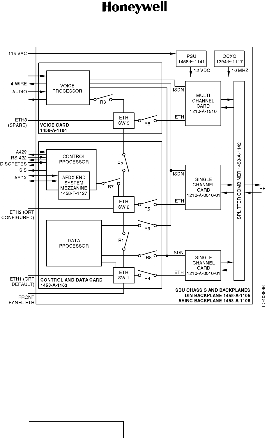
(3) Refer to Figure 8 (GRAPHIC 23-15-30-99B-808-A01) for the A350 SATCOM Avionics System
block diagram.
EFFECTIVITY
ALL 23-15-30 Page 37 of 70
5 Oct 2012
© Honeywell International Inc. Do not copy without express permission of Honeywell.
Interim DRAFT for FCC Approval Purposes
Do Not Use for Maintenance
10-Feb-2013
ABBREVIATED COMPONENT MAINTENANCE MANUAL
1458-A-1101 / 1458-A-1300
Figure 8. (Sheet 1 of 1) A350 SATCOM Avionics System Block Diagram (GRAPHIC 23-15-30-99B-808-A01)
EFFECTIVITY
ALL 23-15-30 Page 38 of 70
5 Oct 2012
© Honeywell International Inc. Do not copy without express permission of Honeywell.
Interim DRAFT for FCC Approval Purposes
Do Not Use for Maintenance
10-Feb-2013

ABBREVIATED COMPONENT MAINTENANCE MANUAL
1458-A-1101 / 1458-A-1300
2. Operation (TASK 23-15-30-870-802-A01)
A. General (Subtask 23-15-30-870-004-A01)
(1) The SDU is an integral component in an AES. Together with the SCM, DLNA, and HGA
subsystem, it achieves all of the requirements for providing AMSS by facilitating airborne
satellite communication services over the Inmarsat network. These services comprise Classic
Aero-H+, Swift64, and SBB.
(2) The SCM is a dedicated peripheral of the SDU and stores aircraft specific installation
configuration critical to the operation of the AES.
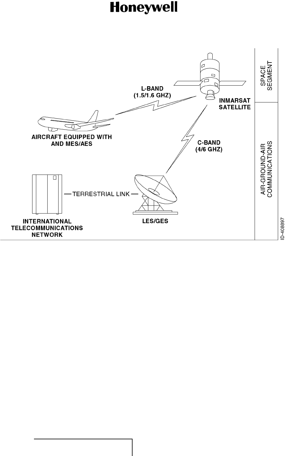
B. Satellite Network Overview (Subtask 23-15-30-870-005-A01)
(1) This section provides a brief overview of the Inmarsat I-3/I-4 satellite communication system.
Satellite communication systems include global satellite networks, GES/LES, and AES/MES.
(2) GES and AES are the terms associated with Aero-H+ services.
(3) Satellite communication systems give users with long-range voice and data communication by
accessing global satellite and ground communications networks.
(4) Inmarsat is an international organization that operates and maintains the satellites and satellite
networks. Inmarsat operates multiple geostationary satellites. Each satellite is
•AORE
•AORW
•IOR
•POR.
(5) All I-3 satellites give worldwide telecommunication services for aviation, shipping, and
land-mobile terminal users. The satellites connect to ground telecommunication systems
through a network of GESs.
(6) In addition to the services offered by I-3 satellites, the I-4 satellites also give worldwide
broadband service, SBB. Each I-4 satellite has 19 wide spot beams, 228 narrow spot beams,
and is capable of accommodating many different, simultaneous SBB sessions. The SBB
service and I-4 satellites support broadband applications such as videoconferencing and
video-streaming.
(7) At the time of publishing, three I-4 satellites are operational:
•Americas
•EMEA
• Asia-Pacific.
(8) The satellite communication avionics (ARINC 781 systems), typically in conjunction with an
antenna subsystem, act as an AES/MES. The combined system provides users with a data
and voice communications link to the satellite network and global telecommunications system.
(9) A simplified satellite communications system is shown in Figure 9 (GRAPHIC
23-15-30-99B-809-A01).
EFFECTIVITY
ALL 23-15-30 Page 39 of 70
5 Oct 2012
© Honeywell International Inc. Do not copy without express permission of Honeywell.
Interim DRAFT for FCC Approval Purposes
Do Not Use for Maintenance
10-Feb-2013
ABBREVIATED COMPONENT MAINTENANCE MANUAL
1458-A-1101 / 1458-A-1300
Figure 9. (Sheet 1 of 1) Simplified Aeronautical Satellite Communications System
(GRAPHIC 23-15-30-99B-809-A01)
C. Software Specifications (Subtask 23-15-30-870-006-A01)
(1) The A350 SDU and SCM operating software meets RTCA/DO-178B Level D requirements.
D. Hardware Specifications (Subtask 23-15-30-870-007-A01)
(1) The A350 SDU and SCM hardware meets RTCA/DO-254 Level D requirements.
E. Equipment Description (Subtask 23-15-30-870-008-A01)
(1) Mechanical
(a) The A350 SATCOM Avionics System consists of the following LRUs:
•SDU
•SCM
• FMPA (optional).
(b) The SDU is divided into several SRUs that are electrically connected through the
backplane. Various SRUs are also connected with the RF cables.
EFFECTIVITY
ALL 23-15-30 Page 40 of 70
5 Oct 2012
© Honeywell International Inc. Do not copy without express permission of Honeywell.
Interim DRAFT for FCC Approval Purposes
Do Not Use for Maintenance
10-Feb-2013
ABBREVIATED COMPONENT MAINTENANCE MANUAL
1458-A-1101 / 1458-A-1300
(c) The SCM is a dedicated peripheral of the SDU. The SCM package envelope and
mounting arrangement conform to ARINC 781-2. The interconnecting cable between the
SDU and the SCM must not be longer than 393.7 inches (10 meters).
1Weight
aThe combined maximum weight of the A350 SDU and SCM is 18.72 pounds
(8.5 kg), exclusive of mounting trays, fans, and interconnecting cable.
2Form Factor
aThe A350 SDU and SCM form factors are compliant with ARINC 781.
3Connectors
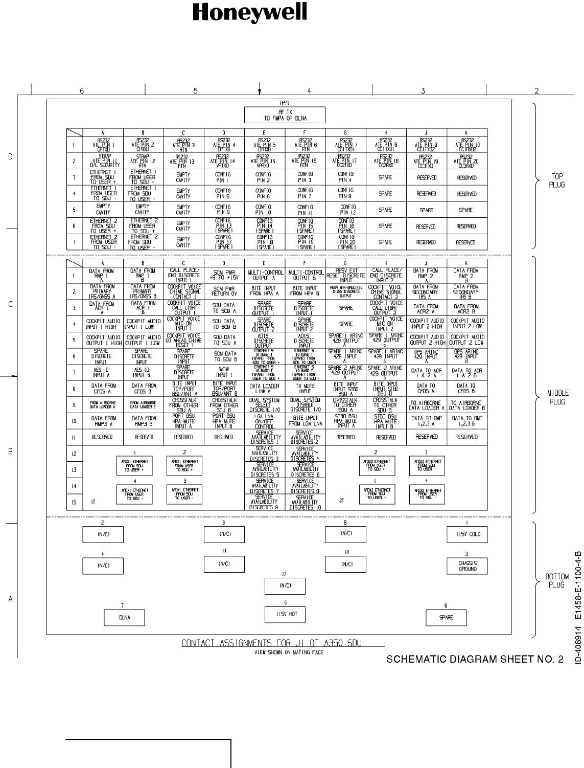
aThe SDU uses two external interface connectors:
• Rear Connector - accommodates coaxial and signal interconnections in
the TP insert, quadrax and signal interconnections in the MP insert, and
coaxial, and power interconnections in the BP insert. The top insert pin
assignment are in accordance with ARINC 781 with the following deviations
as shown in the Table 8.
• Front Connector - an RJ45 and 9S DSUB connector providing 10bT
Ethernet and an RS-232 maintenance interface to the control processor.
Table 8. SDU Rear Connector Pin Deviations
Description Pin Deviation
CP maintenance TXD TP01A ATE p i n 1
CP maintenance RXD TP01B ATE p in 2
CP/DP maintenance GND TP01C ATE p i n 3
Data I/O processor maintenance TXD TP01D ATE p i n 4
Data I/O processor maintenance RXD TP01E ATE p i n 5
CC1 processors #1 and #2 maintenance GND TP01F ATE p i n 6
CC1 processor #1 maintenance TXD TP01G ATE p i n 7
CC1 processor #1 maintenance RXD TP01H ATE p i n 8
CC1 processor #2 maintenance TXD TP01J ATE p i n 9
CC1 processor #2 maintenance RXD TP01K ATE p i n 1 0
Download security TP02A ATE p i n 1 1
No connect TP02B ATE p i n 1 2
Voice processor maintenance GND TP02C ATE p i n 1 3
Voice processor maintenance TXD TP02D ATE p i n 1 4
Voice processor maintenance RXD TP02E ATE p i n 1 5
CC2 and CC3 maintenance GND TP02F ATE p i n 1 6
CC2 processor maintenance TXD TP02G ATE p i n 1 7
CC2 processor maintenance RXD TP02H ATE p i n 1 8
EFFECTIVITY
ALL 23-15-30 Page 41 of 70
5 Oct 2012
© Honeywell International Inc. Do not copy without express permission of Honeywell.
Interim DRAFT for FCC Approval Purposes
Do Not Use for Maintenance
10-Feb-2013
ABBREVIATED COMPONENT MAINTENANCE MANUAL
1458-A-1101 / 1458-A-1300
Description Pin Deviation
CC3 processor maintenance TXD TP02J AT E p i n 1 9
CC3 processor maintenance RXD TP02K AT E p i n 2 0
(d) The SCM uses a 15 pin D-type male connector and locking screws. Pin assignments are
consistent with ARINC 781 as shown in Table 9.
Table 9. SCM D-Type Connector Pin Assignment
Pin Number Description
1Data to SDU A (RS422)
2Data to SDU B (RS422)
3Data from SDU A (RS422)
4Data from SDU B (RS422)
5Reserved - RS232 GND (used for shop loading)
6Spare
7Chassis GND
8Power input (+8 to +15 volts)
9Reserved - Enable RS232 (used for shop loading)
10 Reserved - 0 volt strap output (used for shop loading)
11 Spare
12 Reserved - RS232 Tx (used for shop loading)
13 Reserved - RS232 Rx (used for shop loading)
14 Spare
15 Power return (0 volt)
(2) Electrical
(a) The SDU is divided into the following SRUs:
• Channel card (2)
• Multi-channel card
• SDU control processor and data I/O processor
• AFDX mezzanine card
• SDU voice processor
• Combiner and splitter
• Backplane
• Oven controlled crystal oscillator
• Power supply
•SCM.
EFFECTIVITY
ALL 23-15-30 Page 42 of 70
5 Oct 2012
© Honeywell International Inc. Do not copy without express permission of Honeywell.
Interim DRAFT for FCC Approval Purposes
Do Not Use for Maintenance
10-Feb-2013
ABBREVIATED COMPONENT MAINTENANCE MANUAL
1458-A-1101 / 1458-A-1300
(b) The major interfaces of the SDU are shown in Table 10.
Table 10. SDU Functional Interfaces
Interface Description Type
HGA (x1) HGA/DLNA A429 bus
HPA (x1) HPA A429 bus
RMP (x3) RMU (for Control and Display) A429 bus
AFDX (x2) AFDX AFDX bus
ADIRU virtual links AFDX VL
LGERS virtual links AFDX VL
CMS virtual links AFDX VL
DLCS virtual links AFDX VL
FWS virtual links AFDX VL
DFDRS virtual links AFDX VL
SPP virtual links AFDX VL
SCM (x1) SCM RS422
SCM 12V power SCM power Power
SIS (x1) SIS I2C
Servicing Front panel accessible service port for data log retrieval Ethernet
Miscellaneous ARINC discrete input, outputs and configuration straps Discretes
(c) The frequency of operation is as follows:
• Receive band - 1525.0 to 1559.0 MHz
• Transmit band - 1626.5 to 1660.5 MHz.
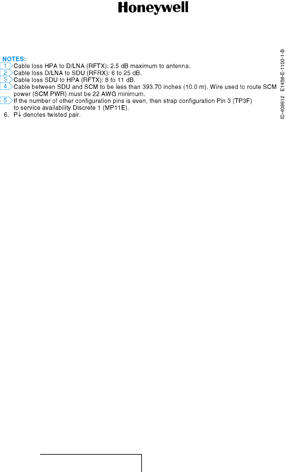
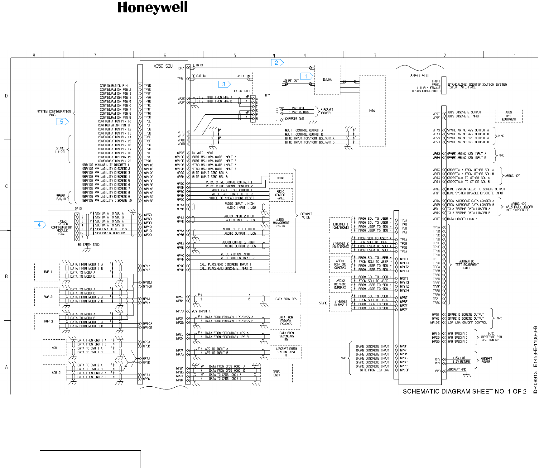
(3) Refer to Figure 10 (GRAPHIC 23-15-30-99B-810-A01) for the System Interconnection Drawing.
EFFECTIVITY
ALL 23-15-30 Page 43 of 70
5 Oct 2012
© Honeywell International Inc. Do not copy without express permission of Honeywell.
Interim DRAFT for FCC Approval Purposes
Do Not Use for Maintenance
10-Feb-2013

ABBREVIATED COMPONENT MAINTENANCE MANUAL
1458-A-1101 / 1458-A-1300
Blank Page
EFFECTIVITY
ALL 23-15-30 Page 44 of 70
5 Oct 2012
© Honeywell International Inc. Do not copy without express permission of Honeywell.
Interim DRAFT for FCC Approval Purposes
Do Not Use for Maintenance
10-Feb-2013
ABBREVIATED COMPONENT MAINTENANCE MANUAL
1458-A-1101 / 1458-A-1300
Figure 10. (Sheet 1 of 3) System Interconnection Drawing (GRAPHIC 23-15-30-99B-810-A01)
EFFECTIVITY
ALL 23-15-30 Pages 45/46 of 70
5 Oct 2012
© Honeywell International Inc. Do not copy without express permission of Honeywell.
Interim DRAFT for FCC Approval Purposes
Do Not Use for Maintenance
10-Feb-2013
Interim DRAFT for FCC Approval Purposes
Do Not Use for Maintenance
10-Feb-2013
ABBREVIATED COMPONENT MAINTENANCE MANUAL
1458-A-1101 / 1458-A-1300
Figure 10. (Sheet 2 of 3) System Interconnection Drawing (GRAPHIC 23-15-30-99B-810-A01)
EFFECTIVITY
ALL 23-15-30 Pages 47/48 of 70
5 Oct 2012
© Honeywell International Inc. Do not copy without express permission of Honeywell.
Interim DRAFT for FCC Approval Purposes
Do Not Use for Maintenance
10-Feb-2013
Interim DRAFT for FCC Approval Purposes
Do Not Use for Maintenance
10-Feb-2013
ABBREVIATED COMPONENT MAINTENANCE MANUAL
1458-A-1101 / 1458-A-1300
Figure 10. (Sheet 3 of 3) System Interconnection Drawing (GRAPHIC 23-15-30-99B-810-A01)
EFFECTIVITY
ALL 23-15-30 Pages 49/50 of 70
5 Oct 2012
© Honeywell International Inc. Do not copy without express permission of Honeywell.
Interim DRAFT for FCC Approval Purposes
Do Not Use for Maintenance
10-Feb-2013
Interim DRAFT for FCC Approval Purposes
Do Not Use for Maintenance
10-Feb-2013
ABBREVIATED COMPONENT MAINTENANCE MANUAL
1458-A-1101 / 1458-A-1300
TESTING AND FAULT ISOLATION
1. Planning Data (TASK 23-15-30-99C-801-A01)
A. Reason for the Job (Subtask 23-15-30-99C-002-A01)
(1) Use the test procedures in this section to test and isolate faults.
(2) The function of the test procedures is to find if there is a failure in the operation of the SDU.
B. Job Setup Data (Subtask 23-15-30-99C-003-A01)
(1) You can use equivalent alternatives for the special tools, fixtures, equipment, and consumable
materials. The user must find equivalent alternatives.
(2) Refer to Table 11 for the specified special tools, fixtures, and equipment in this section.
(3) Refer to H4/H8 CAGE Codes (available at http://www.logisticsinformationservice.dla.mil) for
manufacturer’s address.
Table 11. Special Tools, Fixtures, and Equipment
Number Description Source
Not applicable Not applicable Not applicable
WARNING: BEFORE YOU USE A MATERIAL, REFER TO THE MANUFACTURERS’ MATERIAL
SAFETY DATA SHEETS. SOME MATERIALS CAN BE DANGEROUS.
CAUTION: DO NOT USE MATERIALS THAT ARE NOT EQUIVALENT TO HONEYWELL
SPECIFIED MATERIALS. MATERIALS THAT ARE NOT EQUIVALENT CAN
CAUSE DAMAGE TO THE EQUIPMENT AND CAN MAKE THE WARRANTY NOT
APPLICABLE.
(4) Refer to Table 12 for the specified consumable materials in this section.
Table 12. Consumables
Number Description Source
Not applicable Not applicable Not applicable
(5) The list that follows identifies Honeywell publications that are related to this section:
• Not applicable.
EFFECTIVITY
ALL 23-15-30 Page 51 of 70
5 Oct 2012
© Honeywell International Inc. Do not copy without express permission of Honeywell.
Interim DRAFT for FCC Approval Purposes
Do Not Use for Maintenance
10-Feb-2013

ABBREVIATED COMPONENT MAINTENANCE MANUAL
1458-A-1101 / 1458-A-1300
2. Procedure (TASK 23-15-30-700-801-A01)
A. Job Setup (Subtask 23-15-30-810-001-A01)
WARNING: BEFORE YOU USE A MATERIAL, REFER TO THE MANUFACTURERS’ MATERIAL
SAFETY DATA SHEETS. SOME MATERIALS CAN BE DANGEROUS.
CAUTION: DO NOT USE MATERIALS THAT ARE NOT EQUIVALENT TO HONEYWELL
SPECIFIED MATERIALS. MATERIALS THAT ARE NOT EQUIVALENT CAN
CAUSE DAMAGE TO THE EQUIPMENT AND CAN MAKE THE WARRANTY NOT
APPLICABLE.
CAUTION: DO NOT DROP OR HIT THE SDU DURING THESE PROCEDURES. THE SDU
CONTAINS AN ASSEMBLY THAT CAN BE DAMAGED FROM INCORRECT USE.
CAUTION: DO THESE PROCEDURES IN A CLEAN ENVIRONMENT TO PREVENT DAMAGE
TO MECHANICAL COMPONENTS.
(1) Obey the precautions.
B. BITE (Subtask 23-15-30-810-002-A01)
(1) On power up, the SDU performs a number of invasive BITE tests that are not possible during
normal SDU system operation.
(2) The failure of some of these tests will cause the equipment to go into fail safe mode and
prevent RF transmission. Once entered, safe mode cannot be exited except by fixing the
underlying condition and rebooting.
(3) The SDU implements security segregation whereby the control domain (responsible for classic
aero cockpit functionality) is separated from the data domain (responsible for Ethernet and
swift cabin functionality).
(4) The SDU will respond to a segregation failure by closing-down the user data (Ethernet and
swift RF) interfaces and reporting the condition to both the CMS and security event log
interfaces. If the SDU cannot verify that the user data (Ethernet and swift RF) interfaces are
closed then it will enter a safe mode whereby all interfaces are terminated.
C. LEDs (Subtask 23-15-30-810-003-A01)
(1) The front panel of the SDU has two LEDs to indicate unit status:
• One green LED labelled “Power”
• One red LED labelled “Fault”.
D. Self-Test (Subtask 23-15-30-810-004-A01)
(1) The front panel of the SDU has a recessed button labelled “Test”:
• To reset the unit, press and hold the test button for 5 seconds.
• To initiate self-test (when no LEDs are flashing), momentarily press the test button.
E. Unit Software Load Procedure (Subtask 23-15-30-810-005-A01)
(1) Field-loading of SDU software is not supported. All software upgrades must be accomplished
by the manufacturer.
(2) Field-loading of ORT software is supported through 615A-2 through Ethernet 3.
EFFECTIVITY
ALL 23-15-30 Page 52 of 70
5 Oct 2012
© Honeywell International Inc. Do not copy without express permission of Honeywell.
Interim DRAFT for FCC Approval Purposes
Do Not Use for Maintenance
10-Feb-2013
ABBREVIATED COMPONENT MAINTENANCE MANUAL
1458-A-1101 / 1458-A-1300
F. Fault Isolation (Subtask 23-15-30-810-006-A01)
(1) Testing
(a) Power-Up Test
1The power-up test verifies basic SDU functions and uses the front-panel LEDs
to communicate the results.
2The fault LED indicates several possible internal SDU system problems, not specific
problems, refer to Table 13.
Table 13. LED Status Indicators Table
Power LED State Fault LED State Indicates Action
ON for 60 seconds during
boot-up, then OFF
ON Normal operation during
boot-up
-
OFF OFF Normal operation -
OFF ON LRU fault Use Interactive Mode
BITE via CMS to confirm
fault, remove the LRU
and return it to the factory
OFF Flashing System fault, not
necessarily with the
A350 LRU
Use Interactive Mode
BITE via CMS to isolate
fault, use confirmation
method of suspect LRU
to confirm fault
Flashing Flashing Self-test -
3Some of the possible LRU faults indicated by the lit fault LED include:
• Software image incorrect or corrupted
• Internal busses non-operational
• Internal processors non-functional.
4To fi n d t h e equipment or connection that failed, check the interactive mode BITE
pages. Some examples of possible SDU system faults indicated by the flashing
fault LED includes:
• Strapped configuration does not match the capabilities of the A350 SDU system
or the configuration in the ORT - check the wiring and strapping
• Code images in the SDU do not match the expected configuration - check the
software version and your configuration
• RF path from the SDU to D/LNA failed - check wiring and cable loss settings
• USIM not detected.
(b) Troubleshooting Guidelines
1If the front-panel LEDs signal that the SDU is operating normally and some services
are still not available:
• Verify your SATCOM system - view to satellite, SCM installed
EFFECTIVITY
ALL 23-15-30 Page 53 of 70
5 Oct 2012
© Honeywell International Inc. Do not copy without express permission of Honeywell.
Interim DRAFT for FCC Approval Purposes
Do Not Use for Maintenance
10-Feb-2013

ABBREVIATED COMPONENT MAINTENANCE MANUAL
1458-A-1101 / 1458-A-1300
• Verify your account information - proper login, Inmarsat registration
• Check the SATCOM system using CMS interactive mode maintenance
commands.
(c) Aero-H+ Voice or Data Calls
1Before you can make any Aero-H+ voice or data calls, make sure:
• The Inmarsat registration paperwork is filled out and submitted to the service
provider of choice
• The aircraft has a clear view to the satellite
• Proper power is applied to the SATCOM system
• The INS is aligned - check via IM BITE through the CMS interface
• AIC positional data is provided on the ADIRU interface - check via IM BITE
through the CMS interface
• A valid ICAO address is present on the SPP interface - check via IM BITE
through the CMS interface
• All ARINC 429 interfaces configured as present are present - check via IM BITE
through the CMS interface. If any are not present, spurious faults are raised.
(d) Swift 64 or SBB Calls
1Before you can make any Swift 64 or SBB calls make sure:
• All prerequisites for Aero-H+ calls are followed
• The Aero-H+ service must be logged-on – check via RMP status in the cockpit
• The LES access codes are programmed (Swift 64)
• The forward IDs are present on the SPP bus – check via IM BITE through the
CMS interface
• The USIM modules are installed and activated with the service provider (for
SBB service).
(e) You can download fault logs from the SDU using the IM BITE.
(2) Maintenance Aid Diagrams
(a) No maintenance aid diagrams are required. Return any SDU or SCM units that fail
the operational test procedure provided in this document to the manufacturer for fault
isolation and repair. Refer to APPENDIX A (RMA) (PGBLK 23-15-30-1700) for the
return procedure.
(3) Schematic Change Pages
(a) No schematic change pages are required. Return any SDU or SCM units that fail the
operational test procedure provided in this document to the manufacturer for fault
isolation and repair. Refer to APPENDIX A (RMA) (PGBLK 23-15-30-1700) for the
return procedure.
(4) Modification History
(a) There are currently no service bulletins for the SDU or SCM.
G. Job Close-up (Subtask 23-15-30-810-007-A01)
(1) Not applicable.
SCHEMATIC AND WIRING DIAGRAMS
EFFECTIVITY
ALL 23-15-30 Page 54 of 70
5 Oct 2012
© Honeywell International Inc. Do not copy without express permission of Honeywell.
Interim DRAFT for FCC Approval Purposes
Do Not Use for Maintenance
10-Feb-2013
ABBREVIATED COMPONENT MAINTENANCE MANUAL
1458-A-1101 / 1458-A-1300
1. Not Applicable
DISASSEMBLY
1. Not Applicable
CLEANING
1. Planning Data (TASK 23-15-30-99C-802-A01)
A. Reason for the Job (Subtask 23-15-30-99C-004-A01)
(1) Use these procedures to remove dust, dirt, and unwanted oil and grease. Be careful not to
cause damage to the parts when you do these procedures.
B. Job Setup Data (Subtask 23-15-30-99C-005-A01)
(1) You can use equivalent alternatives for the special tools, fixtures, equipment, and consumable
materials. The user must find equivalent alternatives.
(2) Refer to Table 14 for the specified special tools, fixtures, and equipment in this section.
(3) Refer to H4/H8 CAGE Codes (available at http://www.logisticsinformationservice.dla.mil) for
manufacturer’s address.
Table 14. Special Tools, Fixtures, and Equipment
Number Description Source
Not applicable Not applicable Not applicable
WARNING: BEFORE YOU USE A MATERIAL, REFER TO THE MANUFACTURERS’ MATERIAL
SAFETY DATA SHEETS. SOME MATERIALS CAN BE DANGEROUS.
CAUTION: DO NOT USE MATERIALS THAT ARE NOT EQUIVALENT TO HONEYWELL
SPECIFIED MATERIALS. MATERIALS THAT ARE NOT EQUIVALENT CAN
CAUSE DAMAGE TO THE EQUIPMENT AND CAN MAKE THE WARRANTY NOT
APPLICABLE.
(4) Refer to Table 15 for the specified consumable materials in this section.
Table 15. Consumables
Number Description Source
Not applicable Not applicable Not applicable
(5) The list that follows identifies Honeywell publications that are related to this section:
• Not applicable.
EFFECTIVITY
ALL 23-15-30 Page 55 of 70
5 Oct 2012
© Honeywell International Inc. Do not copy without express permission of Honeywell.
Interim DRAFT for FCC Approval Purposes
Do Not Use for Maintenance
10-Feb-2013

ABBREVIATED COMPONENT MAINTENANCE MANUAL
1458-A-1101 / 1458-A-1300
2. Procedure (TASK 23-15-30-100-801-A01)
A. Job Setup (Subtask 23-15-30-100-001-A01)
WARNING: BEFORE YOU USE A MATERIAL, REFER TO THE MANUFACTURERS’ MATERIAL
SAFETY DATA SHEETS. SOME MATERIALS CAN BE DANGEROUS.
CAUTION: DO NOT USE MATERIALS THAT ARE NOT EQUIVALENT TO HONEYWELL
SPECIFIED MATERIALS. MATERIALS THAT ARE NOT EQUIVALENT CAN
CAUSE DAMAGE TO THE EQUIPMENT AND CAN MAKE THE WARRANTY NOT
APPLICABLE.
CAUTION: DO NOT DROP OR HIT THE A350 SDU AND SCM DURING THESE PROCEDURES.
THE A350 SDU AND SCM CONTAINS AN ASSEMBLY THAT CAN BE DAMAGED
FROM INCORRECT USE.
CAUTION: DO THESE PROCEDURES IN A CLEAN ENVIRONMENT TO PREVENT DAMAGE
TO MECHANICAL COMPONENTS.
(1) Obey the precautions.
(2) Do the procedures in a clean location.
(3) When you use pressurized air to clean assemblies and parts, do not use more air pressure
than is necessary.
(4) After you clean the assemblies and parts, supply protection from moisture, dust, and other
contamination until you do a visual check and assemble the component.
B. Job Close-up (Subtask 23-15-30-100-002-A01)
(1) Not applicable.
INSPECTION/CHECK
1. Planning Data (TASK 23-15-30-99C-803-A01)
A. Reason for the Job (Subtask 23-15-30-99C-006-A01)
(1) Use these procedures to find damage or worn parts and parts that show signs of near failure.
B. Job Setup Data (Subtask 23-15-30-99C-007-A01)
(1) You can use equivalent alternatives for the special tools, fixtures, equipment, and consumable
materials. The user must find equivalent alternatives.
(2) Refer to Table 16 for the specified special tools, fixtures, and equipment in this section.
(3) Refer to H4/H8 CAGE Codes (available at http://www.logisticsinformationservice.dla.mil) for
manufacturer’s address.
Table 16. Special Tools, Fixtures, and Equipment
Number Description Source
Not applicable Not applicable Not applicable
EFFECTIVITY
ALL 23-15-30 Page 56 of 70
5 Oct 2012
© Honeywell International Inc. Do not copy without express permission of Honeywell.
Interim DRAFT for FCC Approval Purposes
Do Not Use for Maintenance
10-Feb-2013
ABBREVIATED COMPONENT MAINTENANCE MANUAL
1458-A-1101 / 1458-A-1300
WARNING: BEFORE YOU USE A MATERIAL, REFER TO THE MANUFACTURERS’ MATERIAL
SAFETY DATA SHEETS. SOME MATERIALS CAN BE DANGEROUS.
CAUTION: DO NOT USE MATERIALS THAT ARE NOT EQUIVALENT TO HONEYWELL
SPECIFIED MATERIALS. MATERIALS THAT ARE NOT EQUIVALENT CAN
CAUSE DAMAGE TO THE EQUIPMENT AND CAN MAKE THE WARRANTY NOT
APPLICABLE.
(4) Refer to Table 17 for the specified consumable materials in this section.
Table 17. Consumables
Number Description Source
Not applicable Not applicable Not applicable
(5) The list that follows identifies Honeywell publications that are related to this section:
(a) Not applicable.
2. Procedure (TASK 23-15-30-210-801-A01)
A. Job Setup (Subtask 23-15-30-210-001-A01)
WARNING: BEFORE YOU USE A MATERIAL, REFER TO THE MANUFACTURERS’ MATERIAL
SAFETY DATA SHEETS. SOME MATERIALS CAN BE DANGEROUS.
CAUTION: DO NOT USE MATERIALS THAT ARE NOT EQUIVALENT TO HONEYWELL
SPECIFIED MATERIALS. MATERIALS THAT ARE NOT EQUIVALENT CAN
CAUSE DAMAGE TO THE EQUIPMENT AND CAN MAKE THE WARRANTY NOT
APPLICABLE.
CAUTION: DO NOT DROP OR HIT THE A350 SDU AND SCM DURING THESE PROCEDURES.
THE A350 SDU AND SCM CONTAINS AN ASSEMBLY THAT CAN BE DAMAGED
FROM INCORRECT USE.
CAUTION: DO THESE PROCEDURES IN A CLEAN ENVIRONMENT TO PREVENT DAMAGE
TO MECHANICAL COMPONENTS.
(1) Obey the precautions.
B. General Inspection/Check Procedure of the A350 SDU and SCM (Subtask 23-15-30-210-
002-A01)
(1) Periodic inspections of the mechanical and electrical interfaces of the SDU and SCM
components to the aircraft must be completed as defined by the governing airworthiness
body’s ICA for the installation (Transport Canada, the FAA, the JAA). Refer to Paragraph 2.D.
(Subtask 23-15-30-210-004-A01) for general guidelines.
(2) Installation of the A350 SATCOM avionics system on an aircraft by STC obligates the aircraft
operator to include the maintenance information supplied by this manual in the operator’s
aircraft maintenance manual and the operator’s aircraft scheduled maintenance program.
C. Instructions for Continued Airworthiness, FAR 25.1529 (Subtask 23-15-30-210-003-A01)
(1) Periodic inspections of the mechanical and electrical interfaces of the A350 SDU system
components to the aircraft should be completed as defined by the governing airworthiness
body’s ICA for the installation (Transport Canada, FAA, and EASA).
(2) Installation of the A350 SATCOM avionics system on an aircraft by STC obligates the aircraft
operator to include the maintenance information supplied by the A350 SATCOM avionics
SDIMM in the operator’s AMM and the operator’s aircraft scheduled maintenance program.
EFFECTIVITY
ALL 23-15-30 Page 57 of 70
5 Oct 2012
© Honeywell International Inc. Do not copy without express permission of Honeywell.
Interim DRAFT for FCC Approval Purposes
Do Not Use for Maintenance
10-Feb-2013

ABBREVIATED COMPONENT MAINTENANCE MANUAL
1458-A-1101 / 1458-A-1300
D. Inspection/Check Schedule (Subtask 23-15-30-210-004-A01)
(1) The SDU and SCM system does not require routine maintenance for continued airworthiness.
(2) Follow the standard practices chapter of the AMM and do all required inspections at a minimum
each year or for every aircraft maintenance requirements and schedule.
E. Unscheduled Maintenance (Subtask 23-15-30-210-005-A01)
(1) Follow the standard practices chapter of the AMM and do all required inspections and repairs.
F. Repair Requirements (Subtask 23-15-30-210-006-A01)
(1) If functional problems occur, the SDU BITE identifies the faulty LRU.
(2) For each continued airworthiness instructions, if an SDU or SCM is inoperative, use the
standard practices chapter of the AMM to:
• Remove the unit.
• Attach cables and wiring.
• Collar applicable switches and circuit breakers, and placard them as “inoperative”.
(3) Before flight, revise the equipment list and weight and balance data as applicable, and record
the removal of the unit in the log book, refer to section 91.213 of the FAR or the aircraft MEL.
(4) All repairs must be performed at Honeywell or a Honeywell approved repair facility.
G. Job Close-up (Subtask 23-15-30-210-007-A01)
(1) Not applicable.
REPAIR
1. Planning Data (TASK 23-15-30-99C-804-A01)
A. Reason for the Job (Subtask 23-15-30-99C-008-A01)
(1) Use these procedures for the A350 SDU and SCM to replace defective parts and replace or
repair defective subassemblies.
B. Job Setup Data (Subtask 23-15-30-99C-009-A01)
(1) You can use equivalent alternatives for the special tools, fixtures, equipment, and consumable
materials. The user must find equivalent alternatives.
(2) Refer to Table 18 for the specified special tools, fixtures, and equipment in this section.
(3) Refer to H4/H8 CAGE Codes (available at http://www.logisticsinformationservice.dla.mil) for
manufacturer’s address.
Table 18. Special Tools, Fixtures, and Equipment
Number Description Source
Not applicable Not applicable Not applicable
EFFECTIVITY
ALL 23-15-30 Page 58 of 70
5 Oct 2012
© Honeywell International Inc. Do not copy without express permission of Honeywell.
Interim DRAFT for FCC Approval Purposes
Do Not Use for Maintenance
10-Feb-2013
ABBREVIATED COMPONENT MAINTENANCE MANUAL
1458-A-1101 / 1458-A-1300
WARNING: BEFORE YOU USE A MATERIAL, REFER TO THE MANUFACTURERS’ MATERIAL
SAFETY DATA SHEETS. SOME MATERIALS CAN BE DANGEROUS.
CAUTION: DO NOT USE MATERIALS THAT ARE NOT EQUIVALENT TO HONEYWELL
SPECIFIED MATERIALS. MATERIALS THAT ARE NOT EQUIVALENT CAN
CAUSE DAMAGE TO THE EQUIPMENT AND CAN MAKE THE WARRANTY NOT
APPLICABLE.
(4) Refer to Table 19 for the specified consumable materials in this section.
Table 19. Consumables
Number Description Source
Not applicable Not applicable Not applicable
(5) The list that follows identifies Honeywell publications that are related to this section:
(a) Not applicable.
2. Procedure (TASK 23-15-30-300-801-A01)
A. Job Setup (Subtask 23-15-30-300-001-A01)
WARNING: BEFORE YOU USE A MATERIAL, REFER TO THE MANUFACTURERS’ MATERIAL
SAFETY DATA SHEETS. SOME MATERIALS CAN BE DANGEROUS.
CAUTION: DO NOT USE MATERIALS THAT ARE NOT EQUIVALENT TO HONEYWELL
SPECIFIED MATERIALS. MATERIALS THAT ARE NOT EQUIVALENT CAN
CAUSE DAMAGE TO THE EQUIPMENT AND CAN MAKE THE WARRANTY NOT
APPLICABLE.
CAUTION: DO NOT DROP OR HIT THE A350 SDU AND SCM DURING THESE PROCEDURES.
THE A350 SDU AND SCM CONTAINS AN ASSEMBLY THAT CAN BE DAMAGED
FROM INCORRECT USE.
CAUTION: DO THESE PROCEDURES IN A CLEAN ENVIRONMENT TO PREVENT DAMAGE
TO MECHANICAL COMPONENTS.
(1) Obey the precautions.
B. General Repair Instructions (Subtask 23-15-30-300-002-A01)
(1) If functional problems occur, the SDU BITE identifies the faulty LRU - check via IM Bite
through the CMS interface.
(2) As per continued airworthiness instructions, if an SDU or SCM is inoperative, use the standard
practices chapter of the AMM to remove the unit, secure cables and wiring, collar applicable
switches and circuit breakers, and placard them as “inoperative”.
(3) Before flight, revise the equipment list and weight and balance data as applicable, and record
the removal of the unit in the log book. Refer to Section 91.213 of the FAR or the aircraft’s MEL.
(4) All repairs must be performed at the Honeywell factory.
C. Job Close-up (Subtask 23-15-30-300-003-A01)
(1) Not applicable.
ASSEMBLY
1. Not Applicable
EFFECTIVITY
ALL 23-15-30 Page 59 of 70
5 Oct 2012
© Honeywell International Inc. Do not copy without express permission of Honeywell.
Interim DRAFT for FCC Approval Purposes
Do Not Use for Maintenance
10-Feb-2013
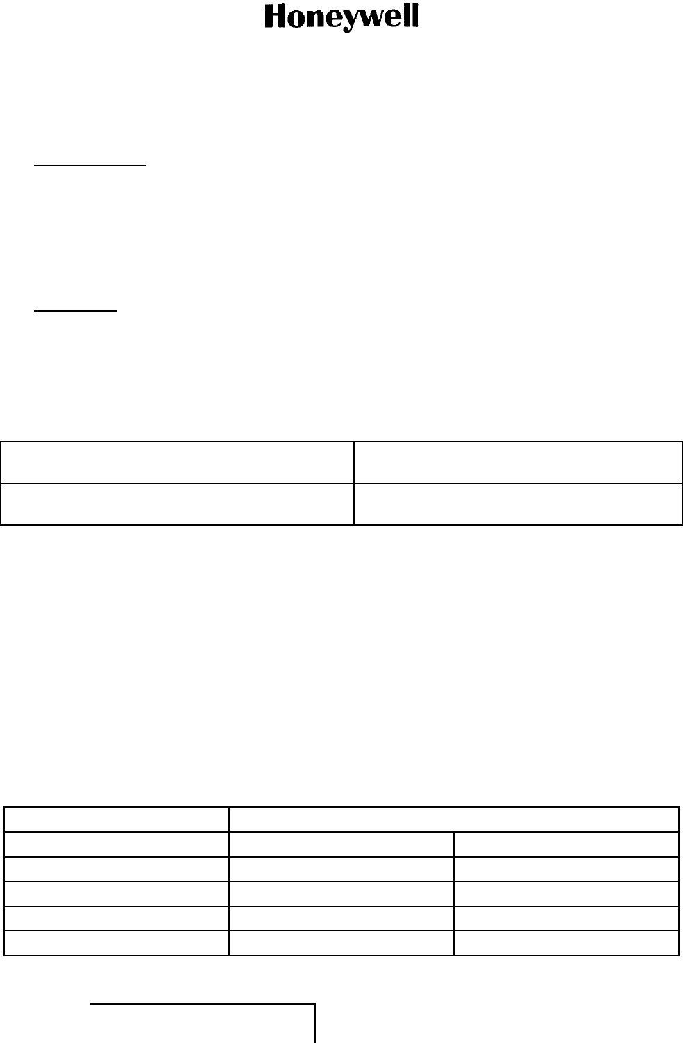
ABBREVIATED COMPONENT MAINTENANCE MANUAL
1458-A-1101 / 1458-A-1300
FITS AND CLEARANCES
1. Planning Data (TASK 23-15-30-99C-805-A01)
A. Reason for the Job (Subtask 23-15-30-99C-010-A01)
(1) This section gives the fits and clearances used when the A350 SDU and SCM was made.
(2) This section gives the torque data required for repair and assembly of the A350 SDU and SCM.
B. Job Setup Data (Subtask 23-15-30-99C-011-A01)
(1) Not applicable.
2. Procedure (TASK 23-15-30-220-801-A01)
A. Job Setup (Subtask 23-15-30-220-001-A01)
(1) Not applicable.
B. Fits and Clearances of the A350 SDU and SCM (Subtask 23-15-30-220-002-A01)
(1) Refer to Table 20 when you do the procedures in INSTALLATION (PGBLK 23-15-30-13000).
Table 20. Fits and Clearances
Nomenclature/Description
Figure - Item Requirement/Dimension
Minimum clearance between the SDU and any other
equipment installed above it
0.50 inch (12.7 mm)
C. Torque Values (Subtask 23-15-30-220-003-A01)
(1) Tighten nuts, bolts, screws, and tube fittings to the standard torque unless specified differently.
Refer to FAA Manual FAA-H-8083-30, Aviation Maintenance Technician Handbook, for
standard torque.
(2) Tighten nuts, bolts, screws, and tube fittings to the standard torque unless specified differently.
(3) Tighten fasteners installed through non-elastic boundaries to remove visible clearance between
the parts. Monitor the rundown torque necessary just before the fastener becomes tight. Then
tighten to the final torque (refer to Table 21 for the correct thread size) and add the rundown
torque. This procedure is sufficient for all fasteners not shown under torque values below.
Refer to Table 22 for final torque data after rundown torque.
(4) Tighten fasteners installed through elastic boundaries (sealed by means of a diaphragm or
similar elastomeric gasket) equally to get a pressure tight seal.
Table 21. Thread Size and Torque Data
Torque in-lb (Nm)
Thread Size Aluminum Fastener CRES Fastener
6-32 5 (0.565) 10 (1.13)
8-32 10 (1.13) 20 (2.26)
10-24 15 (1.695) 35 (3.955)
1/4-20 45 (5.085) 75 (8.475)
EFFECTIVITY
ALL 23-15-30 Page 60 of 70
5 Oct 2012
© Honeywell International Inc. Do not copy without express permission of Honeywell.
Interim DRAFT for FCC Approval Purposes
Do Not Use for Maintenance
10-Feb-2013
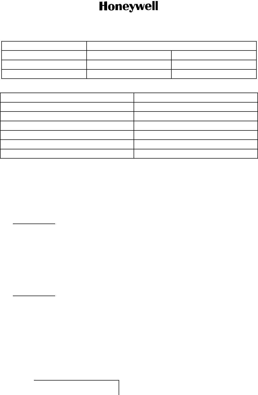
ABBREVIATED COMPONENT MAINTENANCE MANUAL
1458-A-1101 / 1458-A-1300
Torque in-lb (Nm)
Thread Size Aluminum Fastener CRES Fastener
5/16-18 80 (9.04) 160 (18.08)
3/8-24 140 (15.82) 275 (31.075)
Table 22. Final Torque Data
Thread Size Approximate Turn After Run-Down
6-32 45 degrees
8-32 60 degrees
10-24 40 degrees
1/4-20 40 degrees
5/16-18 40 degrees
3/8-24 60 degrees
D. Specified Torque Values (Subtask 23-15-30-220-004-A01)
(1) Not applicable.
E. Job Close-up (Subtask 23-15-30-220-005-A01)
(1) Not applicable.
SPECIAL TOOLS, FIXTURES, EQUIPMENT, AND CONSUMABLES
1. Planning Data (TASK 23-15-30-99C-806-A01)
A. General (Subtask 23-15-30-99C-012-A01)
(1) No special tools, fixtures, or equipment is required. Standard avionics shop tools are the
only equipment required.
SPECIAL PROCEDURES
1. Not Applicable
REMOVAL
1. Planning Data (TASK 23-15-30-99C-807-A01)
A. Reason for the Job (Subtask 23-15-30-99C-013-A01)
(1) Use these procedures to remove the A350 SDU and SCM.
B. Job Setup Data (Subtask 23-15-30-99C-014-A01)
(1) You can use equivalent alternatives for the special tools, fixtures, equipment, and consumable
materials. The user must find equivalent alternatives.
(2) Refer to Table 23 for the specified special tools, fixtures, and equipment in this section.
(3) Refer to H4/H8 CAGE Codes (available at http://www.logisticsinformationservice.dla.mil) for
manufacturer’s address.
EFFECTIVITY
ALL 23-15-30 Page 61 of 70
5 Oct 2012
© Honeywell International Inc. Do not copy without express permission of Honeywell.
Interim DRAFT for FCC Approval Purposes
Do Not Use for Maintenance
10-Feb-2013
ABBREVIATED COMPONENT MAINTENANCE MANUAL
1458-A-1101 / 1458-A-1300
Table 23. Special Tools, Fixtures, and Equipment
Number Description Source
Not applicable Not applicable Not applicable
WARNING: BEFORE YOU USE A MATERIAL, REFER TO THE MANUFACTURERS’ MATERIAL
SAFETY DATA SHEETS. SOME MATERIALS CAN BE DANGEROUS.
CAUTION: DO NOT USE MATERIALS THAT ARE NOT EQUIVALENT TO HONEYWELL
SPECIFIED MATERIALS. MATERIALS THAT ARE NOT EQUIVALENT CAN
CAUSE DAMAGE TO THE EQUIPMENT AND CAN MAKE THE WARRANTY NOT
APPLICABLE.
(4) Refer to Table 24 for the specified consumable materials in this section.
Table 24. Consumable Materials
Number Description Source
Not applicable Not applicable Not applicable
(5) The list that follows identifies Honeywell publications that are related to this section:
• Not applicable.
2. Procedure (TASK 23-15-30-000-801-A01)
A. Job Setup (Subtask 23-15-30-000-001-A01)
WARNING: BEFORE YOU USE A MATERIAL, REFER TO THE MANUFACTURERS’ MATERIAL
SAFETY DATA SHEETS. SOME MATERIALS CAN BE DANGEROUS.
CAUTION: DO NOT USE MATERIALS THAT ARE NOT EQUIVALENT TO HONEYWELL
SPECIFIED MATERIALS. MATERIALS THAT ARE NOT EQUIVALENT CAN
CAUSE DAMAGE TO THE EQUIPMENT AND CAN MAKE THE WARRANTY NOT
APPLICABLE.
CAUTION: DO NOT DROP OR HIT THE A350 SDU AND SCM DURING THESE PROCEDURES.
THE A350 SDU AND SCM CONTAINS AN ASSEMBLY THAT CAN BE DAMAGED
FROM INCORRECT USE.
CAUTION: DO THESE PROCEDURES IN A CLEAN ENVIRONMENT TO PREVENT DAMAGE
TO MECHANICAL COMPONENTS.
(1) Obey the precautions.
B. General (Subtask 23-15-30-000-002-A01)
(1) Only authorized technical personnel, trained in general aviation workmanship, that have a
basic understanding of SATCOM systems must proceed with the following procedure.
C. Removal (Subtask 23-15-30-000-003-A01)
(1) If an SDU must be removed from service for repair, with power removed, disconnect all
equipment from the SDU and then remove it from the ARINC tray.
(2) If a SCM must be removed from service for repair, with power removed, disconnect all
equipment from the SCM and then remove the four mounting screws.
D. Job Close-up (Subtask 23-15-30-000-004-A01)
(1) Not applicable.
EFFECTIVITY
ALL 23-15-30 Page 62 of 70
5 Oct 2012
© Honeywell International Inc. Do not copy without express permission of Honeywell.
Interim DRAFT for FCC Approval Purposes
Do Not Use for Maintenance
10-Feb-2013
ABBREVIATED COMPONENT MAINTENANCE MANUAL
1458-A-1101 / 1458-A-1300
INSTALLATION
1. Planning Data (TASK 23-15-30-99C-808-A01)
A. Reason for the Job (Subtask 23-15-30-99C-015-A01)
(1) Use these procedures to install the A350 SDU and SCM.
B. Job Setup Data (Subtask 23-15-30-99C-016-A01)
(1) You can use equivalent alternatives for the special tools, fixtures, equipment, and consumable
materials. The user must find equivalent alternatives.
(2) Refer to Table 25 for the specified special tools, fixtures, and equipment in this section.
(3) Refer to H4/H8 CAGE Codes (available at http://www.logisticsinformationservice.dla.mil) for
manufacturer’s address.
Table 25. Special Tools, Fixtures, and Equipment
Number Description Source
Not applicable Not applicable Not applicable
WARNING: BEFORE YOU USE A MATERIAL, REFER TO THE MANUFACTURERS’ MATERIAL
SAFETY DATA SHEETS. SOME MATERIALS CAN BE DANGEROUS.
CAUTION: DO NOT USE MATERIALS THAT ARE NOT EQUIVALENT TO HONEYWELL
SPECIFIED MATERIALS. MATERIALS THAT ARE NOT EQUIVALENT CAN
CAUSE DAMAGE TO THE EQUIPMENT AND CAN MAKE THE WARRANTY NOT
APPLICABLE.
(4) Refer to Table 26 for the specified consumable materials in this section.
Table 26. Consumable Materials
Number Description Source
Not applicable Not applicable Not applicable
(5) The list that follows identifies Honeywell publications that are related to this section:
• Not applicable.
EFFECTIVITY
ALL 23-15-30 Page 63 of 70
5 Oct 2012
© Honeywell International Inc. Do not copy without express permission of Honeywell.
Interim DRAFT for FCC Approval Purposes
Do Not Use for Maintenance
10-Feb-2013

ABBREVIATED COMPONENT MAINTENANCE MANUAL
1458-A-1101 / 1458-A-1300
2. Procedure (TASK 23-15-30-400-801-A01)
A. Job Setup (Subtask 23-15-30-400-001-A01)
WARNING: BEFORE YOU USE A MATERIAL, REFER TO THE MANUFACTURERS’ MATERIAL
SAFETY DATA SHEETS. SOME MATERIALS CAN BE DANGEROUS.
CAUTION: DO NOT USE MATERIALS THAT ARE NOT EQUIVALENT TO HONEYWELL
SPECIFIED MATERIALS. MATERIALS THAT ARE NOT EQUIVALENT CAN
CAUSE DAMAGE TO THE EQUIPMENT AND CAN MAKE THE WARRANTY NOT
APPLICABLE.
CAUTION: DO NOT DROP OR HIT THE A350 SDU AND SCM DURING THESE PROCEDURES.
THE A350 SDU AND SCM CONTAINS AN ASSEMBLY THAT CAN BE DAMAGED
FROM INCORRECT USE.
CAUTION: DO THESE PROCEDURES IN A CLEAN ENVIRONMENT TO PREVENT DAMAGE
TO MECHANICAL COMPONENTS.
(1) Obey the precautions.
B. Installation Data (Subtask 23-15-30-400-002-A01)
(1) Installation requirements are based on ARINC 781 specifications.
C. Unpacking and Inspecting Equipment (Subtask 23-15-30-400-003-A01)
(1) Unpack the equipment components from the shipping container. Visually inspect the units for
any shipping damage. Make sure that both the SDU and SCM are available.
• SDU PN 1394-A-1100
• SCM PN 1394-A-1300.
(2) If optional parts have been ordered, these items must be removed from the packaging and
visually inspected for any shipping damage.
D. Customer Acceptance Procedure (Subtask 23-15-30-400-004-A01)
(1) Make sure that the part number on the equipment received is correct as ordered.
(2) Check for physical damage that can occurred during shipping.
(3) Check the operational status of the SDU and SCM before installation on an aircraft by
performing the test procedures described in TESTING AND FAULT ISOLATION (PGBLK
23-15-30-1000).
E. Installation Procedure (Subtask 23-15-30-400-005-A01)
(1) General
(a) Only authorized technical personnel, trained in general aviation workmanship, that have a
basic understanding of SATCOM systems must proceed with the following procedure.
Before performing any installation procedures, read the safety advisories.
(2) SDU Installation
(a) Refer to Figure 11 (GRAPHIC 23-15-30-99B-811-A01).
(b) The A350 SDU uses ARINC 600 size 2 shell receptacles located at the rear of the unit
and requires an ARINC 600 6 MCU tray for installation.
(c) Refer to the interconnection diagrams to install the correct wiring for the services you
require. The interconnection and pinout drawings are also provided for information
purposes.
EFFECTIVITY
ALL 23-15-30 Page 64 of 70
5 Oct 2012
© Honeywell International Inc. Do not copy without express permission of Honeywell.
Interim DRAFT for FCC Approval Purposes
Do Not Use for Maintenance
10-Feb-2013
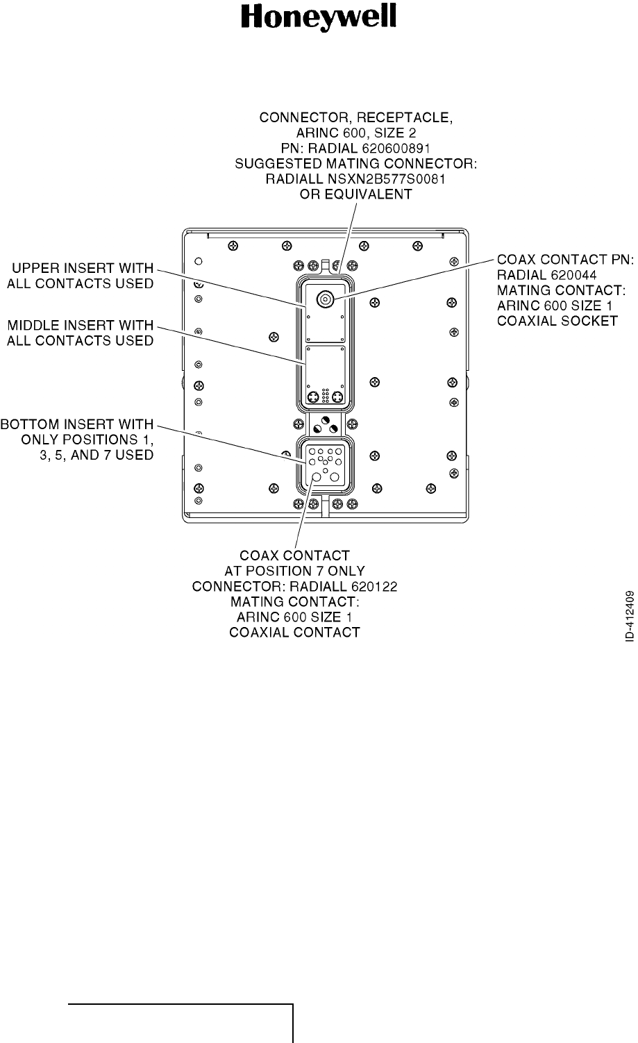
ABBREVIATED COMPONENT MAINTENANCE MANUAL
1458-A-1101 / 1458-A-1300
Figure 11. (Sheet 1 of 1) SDU Back View (GRAPHIC 23-15-30-99B-811-A01)
(3) SCM Installation
(a) Refer to Figure 12 (GRAPHIC 23-15-30-99B-812-A01).
(b) The A350 SCM can be installed in any orientation, but must be mounted on a flat surface.
(c) The A350 SCM must be provided with a low impedance bonding path (less than 2.5
milliohms to airframe ground) to a point on its base.
(d) After the SCM is mounted, connect it to the SDU using a connector cable as per the
SCM and SDU interconnection diagrams.
EFFECTIVITY
ALL 23-15-30 Page 65 of 70
5 Oct 2012
© Honeywell International Inc. Do not copy without express permission of Honeywell.
Interim DRAFT for FCC Approval Purposes
Do Not Use for Maintenance
10-Feb-2013
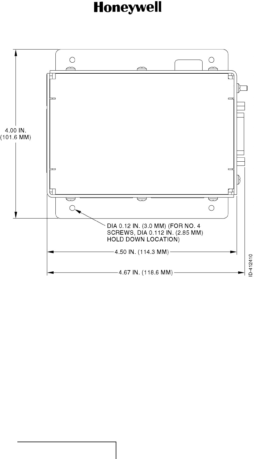
ABBREVIATED COMPONENT MAINTENANCE MANUAL
1458-A-1101 / 1458-A-1300
Figure 12. (Sheet 1 of 1) SCM Top View (GRAPHIC 23-15-30-99B-812-A01)
F. Test (Subtask 23-15-30-400-006-A01)
(1) Do the operational test procedures described in TESTING AND FAULT ISOLATION (PGBLK
23-15-30-1000).
G. Job Close-up (Subtask 23-15-30-400-007-A01)
(1) Not applicable.
SERVICING
1. Not Applicable
STORAGE (INCLUDING TRANSPORTATION)
EFFECTIVITY
ALL 23-15-30 Page 66 of 70
5 Oct 2012
© Honeywell International Inc. Do not copy without express permission of Honeywell.
Interim DRAFT for FCC Approval Purposes
Do Not Use for Maintenance
10-Feb-2013
ABBREVIATED COMPONENT MAINTENANCE MANUAL
1458-A-1101 / 1458-A-1300
1. Planning Data (TASK 23-15-30-99C-809-A01)
A. Reason for the Job (Subtask 23-15-30-99C-017-A01)
(1) Use these procedures to prepare the A350 SDU and SCM for storage or transportation. The
function of these procedures is to make sure that the A350 SDU and SCM has protection from
dust, moisture, and other contamination.
B. Job Setup Data (Subtask 23-15-30-99C-018-A01)
(1) You can use equivalent alternatives for the special tools, fixtures, equipment, and consumable
materials. The user must find equivalent alternatives.
(2) Refer to Table 27 for the specified special tools, fixtures, and equipment in this section.
(3) Refer to H4/H8 CAGE Codes (available at http://www.logisticsinformationservice.dla.mil) for
manufacturer’s address.
Table 27. Special Tools, Fixtures, and Equipment
Number Description Source
Not applicable Not applicable Not applicable
WARNING: BEFORE YOU USE A MATERIAL, REFER TO THE MANUFACTURERS’ MATERIAL
SAFETY DATA SHEETS. SOME MATERIALS CAN BE DANGEROUS.
CAUTION: DO NOT USE MATERIALS THAT ARE NOT EQUIVALENT TO HONEYWELL
SPECIFIED MATERIALS. MATERIALS THAT ARE NOT EQUIVALENT CAN
CAUSE DAMAGE TO THE EQUIPMENT AND CAN MAKE THE WARRANTY NOT
APPLICABLE.
(4)Refer to Table 28 for the specified consumable materials in this section.
Table 28. Consumables
Number Description Source
Not applicable Not applicable Not applicable
(5) The list that follows identifies Honeywell publications that are related to this section:
• Not applicable.
EFFECTIVITY
ALL 23-15-30 Page 67 of 70
5 Oct 2012
© Honeywell International Inc. Do not copy without express permission of Honeywell.
Interim DRAFT for FCC Approval Purposes
Do Not Use for Maintenance
10-Feb-2013

ABBREVIATED COMPONENT MAINTENANCE MANUAL
1458-A-1101 / 1458-A-1300
2. Procedure (TASK 23-15-30-550-801-A01)
A. Job Setup (Subtask 23-15-30-550-001-A01)
WARNING: BEFORE YOU USE A MATERIAL, REFER TO THE MANUFACTURERS’ MATERIAL
SAFETY DATA SHEETS. SOME MATERIALS CAN BE DANGEROUS.
CAUTION: DO NOT USE MATERIALS THAT ARE NOT EQUIVALENT TO HONEYWELL
SPECIFIED MATERIALS. MATERIALS THAT ARE NOT EQUIVALENT CAN
CAUSE DAMAGE TO THE EQUIPMENT AND CAN MAKE THE WARRANTY NOT
APPLICABLE.
CAUTION: DO NOT DROP OR HIT THE A350 SDU AND SCM DURING THESE PROCEDURES.
THE A350 SDU AND SCM CONTAINS AN ASSEMBLY THAT CAN BE DAMAGED
FROM INCORRECT USE.
CAUTION: DO THESE PROCEDURES IN A CLEAN ENVIRONMENT TO PREVENT DAMAGE
TO MECHANICAL COMPONENTS.
(1) Obey the precautions.
B. Preservation (Subtask 23-15-30-550-002-A01)
(1) Not applicable.
C. Packing (Subtask 23-15-30-550-003-A01)
(1) Not applicable.
D. Storage (Subtask 23-15-30-550-004-A01)
(1) Store the A350 SDU and SCM equipment in a cool, dry place [ground survival temperature
range is 67 to 185 F( 55 to +85 C)] in its original shipping container.
E. Transportation (Subtask 23-15-30-550-005-A01)
(1) Not applicable.
F. J o b C l o s e - up (Subtask 23-15-30-550-006-A01)
(1) Not applicable.
REWORK
1. Planning Data (TASK 23-15-30-99F-806-A01)
A. General (Subtask 23-15-30-99F-014-A01)
(1) Rework is not supported in the field. Return any SDU or SCM units that fail the test procedures
provided in this document to the manufacturer for fault isolation and repair. Refer to APPENDIX
A (RMA) (PGBLK 23-15-30-1700) for the return procedure.
APPENDIX A (RMA)
1. Planning Data(TASK 23-15-30-99F-807-A01)
A. General (Subtask 23-15-30-99C-019-A01)
(1) To return the equipment to Honeywell for repair, this RMA procedure must be followed. Failure
to comply with this procedure can result in shipping delays and additional charges.
EFFECTIVITY
ALL 23-15-30 Page 68 of 70
5 Oct 2012
© Honeywell International Inc. Do not copy without express permission of Honeywell.
Interim DRAFT for FCC Approval Purposes
Do Not Use for Maintenance
10-Feb-2013

ABBREVIATED COMPONENT MAINTENANCE MANUAL
1458-A-1101 / 1458-A-1300
B. Warranty Returns (Subtask 23-15-30-99C-020-A01)
(1) Equipment that qualifies for warranty repair can be returned to Honeywell for repair or
replacement at our discretion. The customer must pay the shipping costs to Honeywell and
Honeywell will pay the shipping costs to return the repaired/replaced unit to the customer.
C. Non-Warranty Returns (Subtask 23-15-30-99C-021-A01)
(1) Equipment that fails to work properly because of improper or negligent use, abuse, shipping
damage, or any other condition can still be returned to Honeywell for repair or replacement
at our discretion. The customer will be notified of the cost to repair or replace the unit
before invoicing for the repair or replacement. The customer must pay for the shipping costs
to and from Honeywell.
D. Repackaging Requirements (Subtask 23-15-30-99C-022-A01)
(1) A350 SDU and SCM components must be returned to Honeywell in approved shipping
containers. Failure to do so can invalidate the warranty.
(2) If SDU or SCM shipping containers are unavailable, they can be ordered from Honeywell
customer service when requesting the RMA number.
2. Procedure (TASK 23-15-30-600-801-A01)
A. RMA (Subtask 23-15-30-600-001-A01)
(1) If it is determined that a unit must be returned to Honeywell for repair or overhaul, please
follow the RMA procedure below.
(2) Have the following information ready before calling Honeywell customer support:
• Model (e.g., A350 SDU or SCM)
• Unit part number (e.g., 1458-A-1101 or 1458-A-1300)
• Serial number
• Description of failure
• Aircraft tail number, serial number, and aircraft model number.
(3) Call Honeywell customer support, refer to Paragraph 2 (TASK 23-15-30-99F-802-A01).
(4) A Honeywell product support specialist will attempt to resolve the problem by telephone. If
equipment must be returned to Honeywell, the product support specialist will authorize the
Repair & Overhaul coordinator to issue an RMA number.
(5) Pack the equipment in the original shipping container or a container approved by Honeywell.
(6) Write the RMA number on the outside of the shipping container and on all shipping documents,
enclose a copy in the box, and send your prepaid shipment to:
Honeywell International Inc.
400 Maple Grove Road
Ottawa, Ontario,
CANADA K2V 1B8
RMA #: ___________
ATTN: Repair & Overhaul
Tel: 613 591-6040 extension 1214
Fax: 613 591-8951
EFFECTIVITY
ALL 23-15-30 Page 69 of 70
5 Oct 2012
© Honeywell International Inc. Do not copy without express permission of Honeywell.
Interim DRAFT for FCC Approval Purposes
Do Not Use for Maintenance
10-Feb-2013

ABBREVIATED COMPONENT MAINTENANCE MANUAL
1458-A-1101 / 1458-A-1300
Email: rmareturns@emsaviation.com
(7) Fax or email the details of the shipment to the Repair & Overhaul coordinator, including the
following information: Shipment date, carrier name, and the waybill number.
(8) The processing of LRU returns is limited to standard business hours from 8:30 am to 5:00
pm EST. For general inquires and status requests, please contact the Repair & Overhaul
department directly:
Phone: 613-591-9064, extension 1214 (Repair & Overhaul group)
Fax: 613-591-8951
Email: rmareturns@emsaviation.com
ILLUSTRATED PARTS LIST
1. Not Applicable
EFFECTIVITY
ALL 23-15-30 Page 70 of 70
5 Oct 2012
© Honeywell International Inc. Do not copy without express permission of Honeywell.
Interim DRAFT for FCC Approval Purposes
Do Not Use for Maintenance
10-Feb-2013