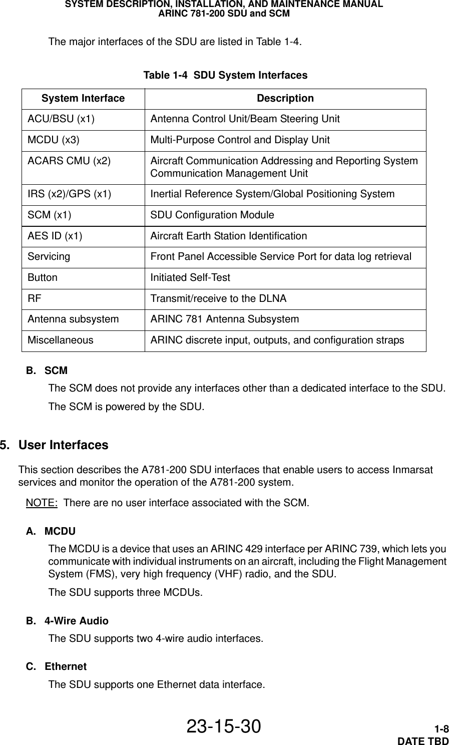
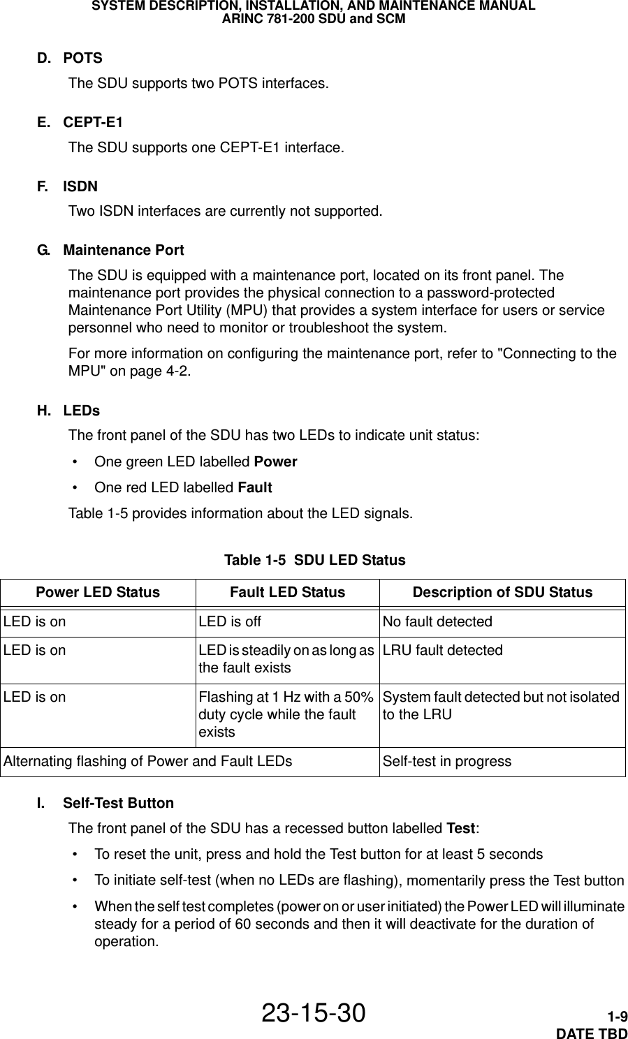
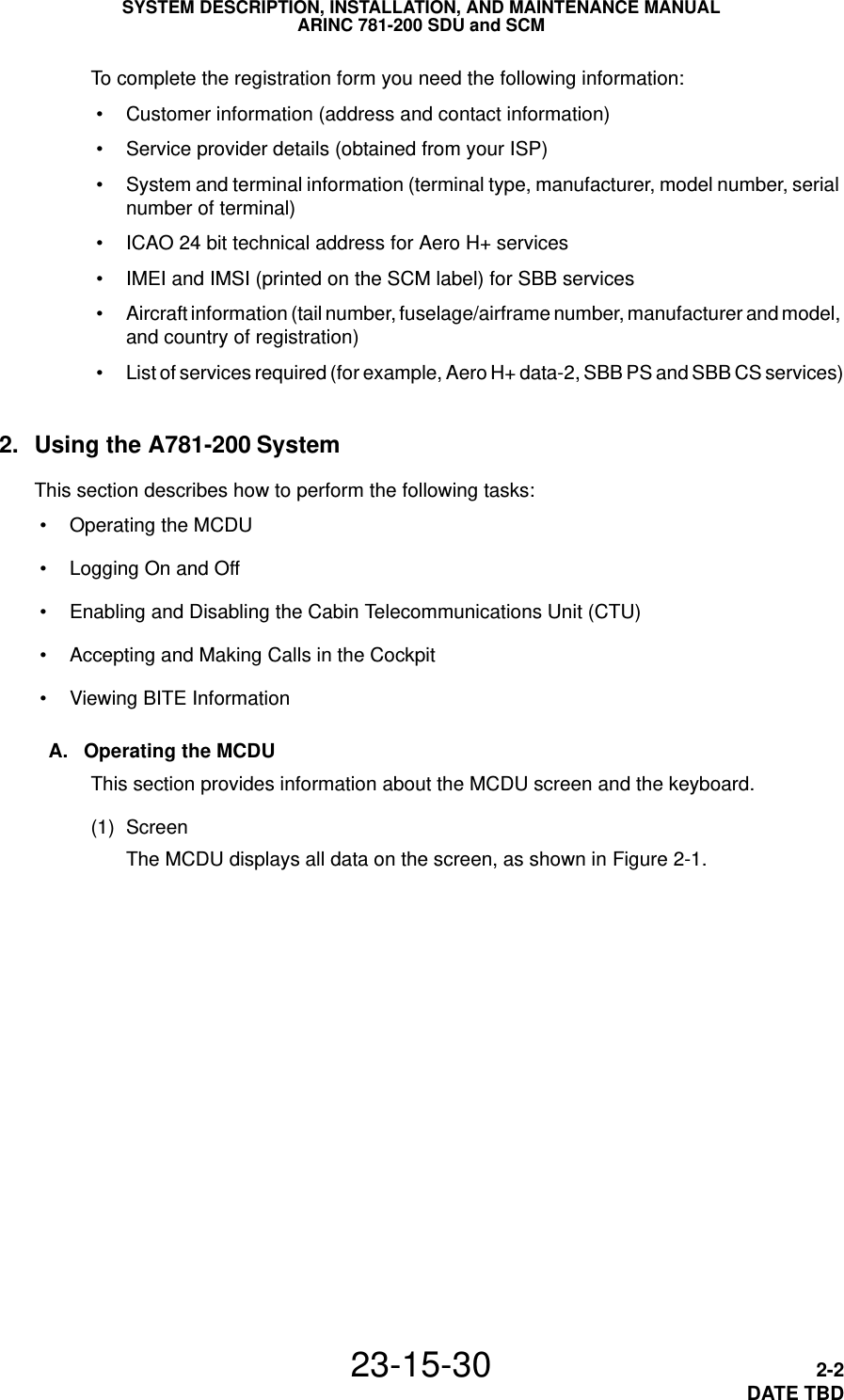
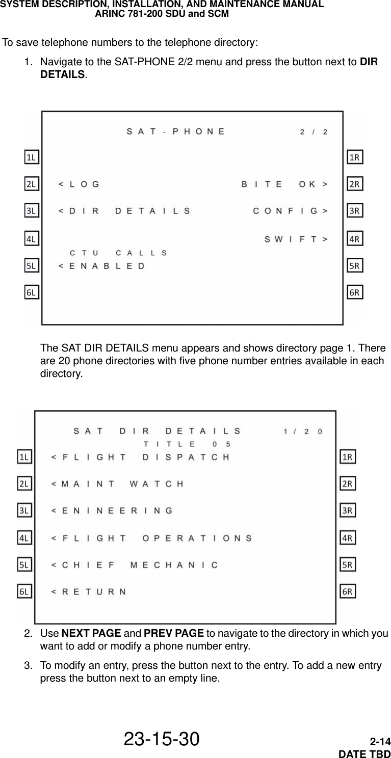
EMS Technologies Canada A781-MK3 A781-200 Satcom Transceiver User Manual MN 0000243
EMS Technologies Canada, Ltd. A781-200 Satcom Transceiver MN 0000243
UserManual.wiki
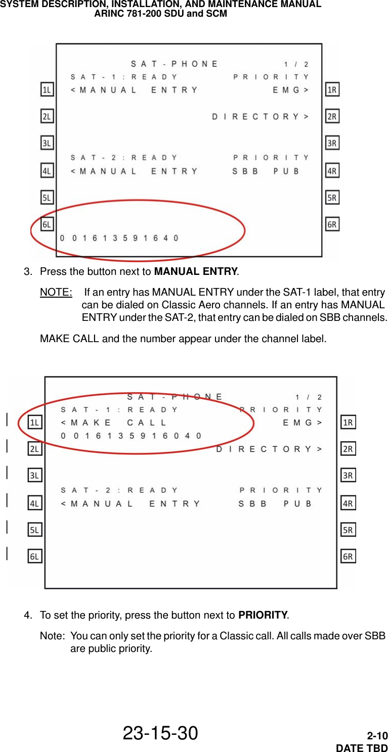
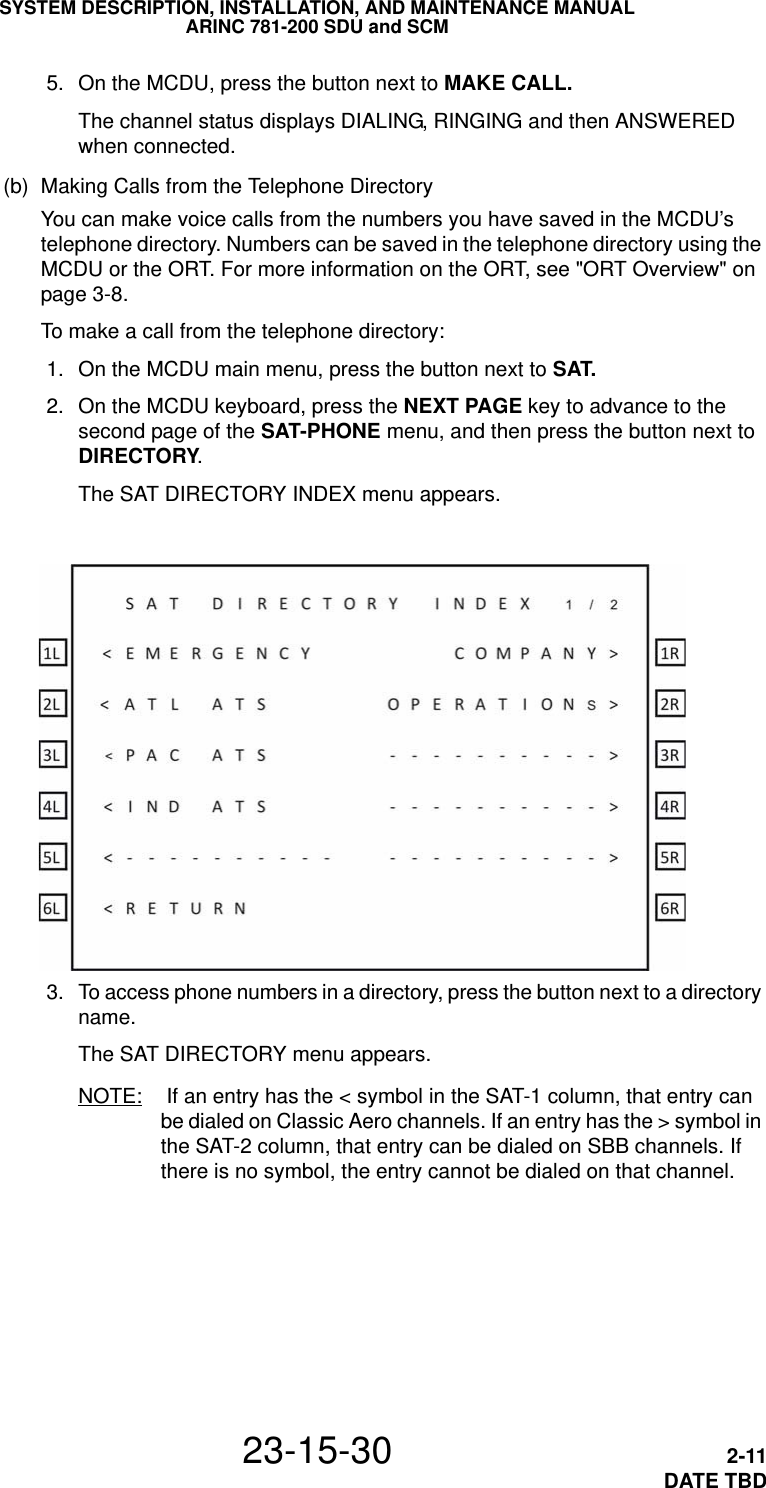
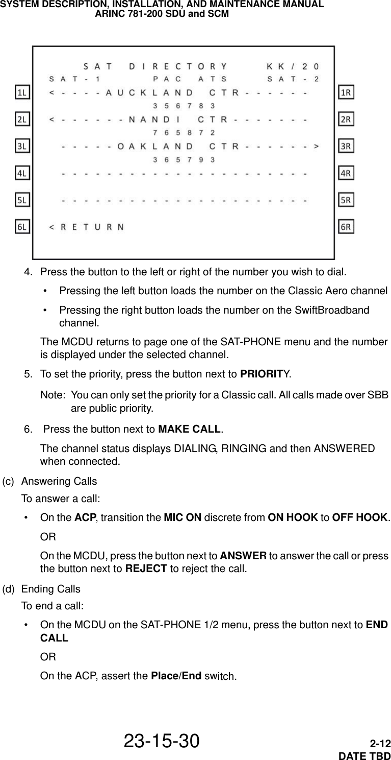
>
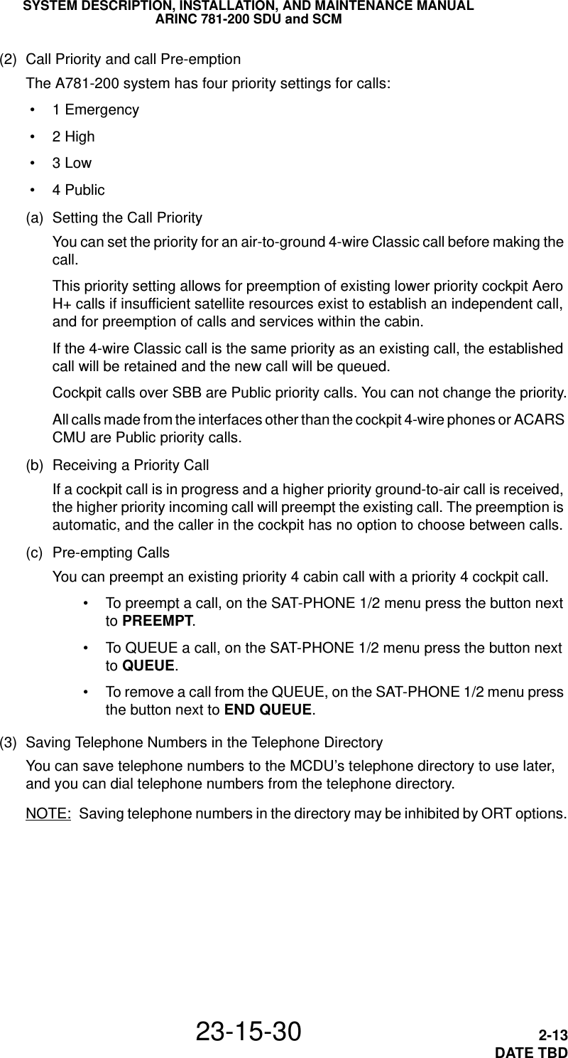
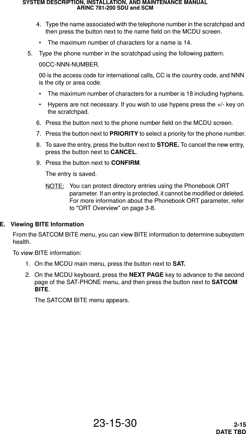
EMS Technologies Canada
>
A781 MK3 User Manual
User's Manual
Navigation menu
Upload a User Manual
Namespaces
Wiki Guide
HTML
PDF
Info
Views
User Manual
Discussion / Help
Navigation


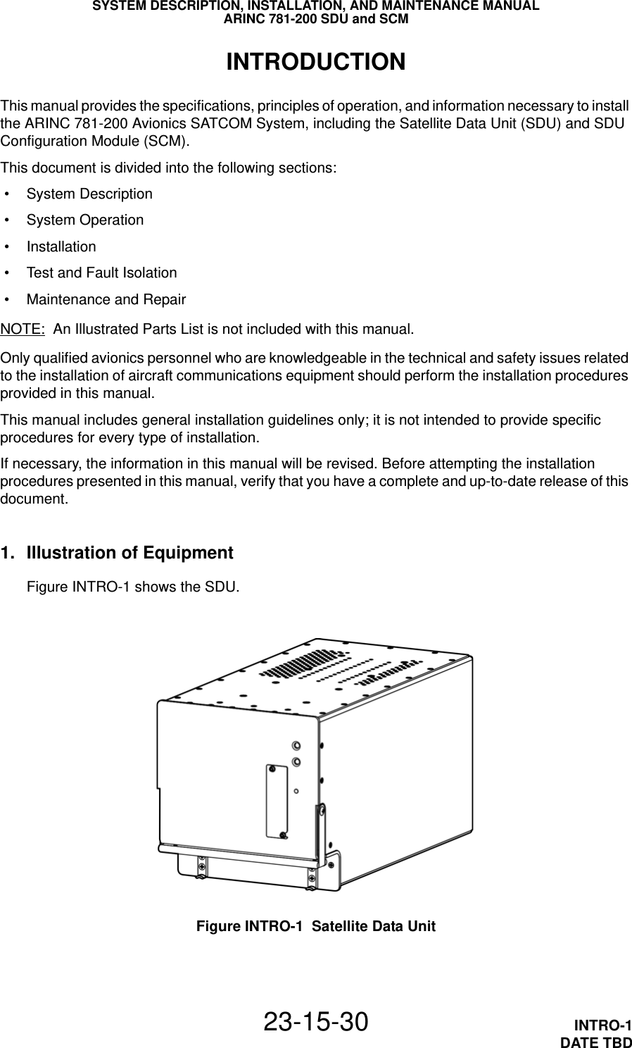


![SYSTEM DESCRIPTION, INSTALLATION, AND MAINTENANCE MANUALARINC 781-200 SDU and SCM23-15-30 4-16DATE TBD[RCI to complete]RCI Product Support may ask you to capture and send them system specific logs and reports.To access logs: 1. In the maintenance port menus, navigate to Menu 3. 2. Turn on the text capture feature of the terminal emulator on your computer.In HyperTerminal, click Transfer, and then click Capture Text. 3. To view the call log, in Menu 3, press F. 4. Turn off the text capture feature of the terminal emulator and send the captured file to RCI Product Support.To access reports: 1. Turn on the text capture feature of the terminal emulator on your computer. In HyperTerminal, click Transfer, and then click Capture Text. 2. In the maintenance port menus, press EQUAL SIGN (=).A list of reports appears. 3. To activate a report, type the number next to the report description, and then press ENTER.NOTE: RCI Product Support will specify the required reports, and may ask you to operate the A781-200 equipment while the reports gather information. 4. To stop a report, press EQUAL SIGN (=), then type the number of the report, and then press ENTER.NOTE: To stop all reports, press X. 5. Turn off the text capture feature of the terminal emulator and send the captured file to RCI Product Support.3. Adjustment/Alignment ProceduresThere are no adjustment/alignment procedures required for the A781-200 system.4. Modification HistoryThe A781-200 system currently has no history of modifications.](https://usermanual.wiki/EMS-Technologies-Canada/A781-MK3/User-Guide-1735968-Page-104.png)
![SYSTEM DESCRIPTION, INSTALLATION, AND MAINTENANCE MANUALARINC 781-200 SDU and SCM23-15-30 5-1DATE TBDMAINTENANCE AND REPAIRThis section provides maintenance and repair information for the A781-200 system, including the following sections: • Maintenance • Repair • Instructions for Continued Airworthiness • Visual Inspection and Check1. MaintenanceThe A781-200 system does not require routine maintenance.2. RepairIf functional problems occur, the SDU BITE identifies the faulty LRU.As per continued airworthiness instructions, if an SDU or SCM is inoperative, use the Standard Practices Chapter of the Aircraft Maintenance Manual to: • remove the unit • secure cables and wiring • collar applicable switches and circuit breakers, and placard them as “inoperative”Before flight, revise the equipment list and weight and balance data as applicable, and record the removal of the unit in the log book [refer to section 91.213 of the FAR or the aircraft’s minimum equipment list (MEL)].All repairs must be performed at the RCI equipment supplier factory.3. Instructions for Continued AirworthinessPeriodic inspections of the mechanical and electrical interfaces of the A781-200 system components to the aircraft should be completed as defined by the governing airworthiness body’s Instructions for Continued Airworthiness (ICA) for the installation (for example, Transport Canada, the FAA, the EASA).Installation of the ARINC 781 SATCOM Avionics System on an aircraft by Supplemental Type Certificate (STC) obligates the aircraft operator to include the maintenance information supplied by this manual in the operator’s Aircraft Maintenance manual and the operator’s Aircraft Scheduled Maintenance Program. This section provides the special instructions and maintenance requirements for continued airworthiness of the A781-200 system.](https://usermanual.wiki/EMS-Technologies-Canada/A781-MK3/User-Guide-1735968-Page-105.png)
![SYSTEM DESCRIPTION, INSTALLATION, AND MAINTENANCE MANUALARINC 781-200 SDU and SCM23-15-30 A-1DATE TBDAPPENDIX A: RETURN MATERIAL AUTHORIZATIONTo return equipment to RCI for repair, this RMA procedure must be followed. Failure to comply with this procedure may result in shipping delays and additional charges.1. Warranty ReturnsEquipment that qualifies for warranty repair can be returned to RCI for repair or replacement at their discretion. The customer shall pay the shipping costs to RCI and RCI will pay the shipping costs to return the repaired/replaced unit to the customer.2. Non-Warranty ReturnsEquipment that fails to work properly because of improper or negligent use, abuse, shipping damage, or any other condition can still be returned to RCI for repair or replacement at their discretion. The customer will be notified of the cost to repair or replace the unit before invoicing for the repair or replacement. The customer shall pay for the shipping costs to and from RCI.3. Repackaging RequirementsARINC 781 SDU or SCM components must be returned to RCI in approved shipping containers. Failure to do so may invalidate the warranty.If SDU or SCM shipping containers are unavailable, they can be ordered from RCI when requesting the RMA number.4. RMA ProcedureIf it is determined that equipment must be returned to RCI for repair or overhaul, follow the RMA procedure below. 1. Have the following information ready before calling RCI Product Support: • Model (e.g., A781-200 SDU) • Unit part number (e.g., 1530-A-1100, 1530-A-1300-01 or 1530-A-1300-02) • Serial number • Description of failure • Aircraft tail number, serial number, and aircraft model number 2. Call RCI Product Support at [RCI to complete]. 3. An RCI Product Support specialist will attempt to resolve the problem by telephone. If equipment must be returned to RCI, the Product Support Specialist will authorize the R&O Coordinator to issue an RMA number. 4. Pack the equipment in the original shipping container or a container approved by RCI.](https://usermanual.wiki/EMS-Technologies-Canada/A781-MK3/User-Guide-1735968-Page-109.png)
![SYSTEM DESCRIPTION, INSTALLATION, AND MAINTENANCE MANUALARINC 781-200 SDU and SCM23-15-30 A-2DATE TBD 5. Write the RMA number on the outside of the shipping container and on all shipping documents, enclose a copy in the box, and send your prepaid shipment to RCI.[RCI to complete] 6. Fax or email the details of the shipment to the R&O Coordinator, including the following information: Shipment date, carrier name, and the waybill number. 7. The processing of LRU returns is limited to standard business hours from 8:30 am to 5:00 pm EST. For general inquires and status requests, contact the R&O department directly:Phone: [RCI to complete]Email: [RCI to complete]Fax: [RCI to complete]](https://usermanual.wiki/EMS-Technologies-Canada/A781-MK3/User-Guide-1735968-Page-110.png)