EMS Technologies Canada A781-MK3 A781-200 Satcom Transceiver User Manual MN 0000243
EMS Technologies Canada, Ltd. A781-200 Satcom Transceiver MN 0000243
User's Manual

23-15-30 TITLE PAGE T-1
DATE TBD
ARINC 781-200 SDU and SCM
System Description, Installation, and Maintenance Manual
MN-0000243, Revision 1.0
This document provides procedures for the equipment listed below.
Model Part Number
ARINC 781-200 Satellite Data Unit 1530-A-1100
ARINC 781-200 SDU Configuration Module—Single
SBB 1530-A-1300-01
ARINC 781-200 SDU Configuration Module—Dual
SBB 1530-A-1300-02

23-15-30 TITLE PAGE T-2
DATE TBD
PROPRIETARY STATEMENT
This document contains information that is proprietary and confidential to either or both of EMS Technologies
Canada, Ltd., or EMS Aviation Inc. (collectively "EMS Aviation") and is supplied on the express condition that
it is not to be used for any purpose other than the purpose for which it was issued, nor is it to be copied or
communicated in whole or in part, to any third party other than the recipient organization, without the prior
written permission of EMS Aviation.
© 2012 EMS Technologies Canada, Ltd., EMS Aviation Inc.
ARINC 781-200 SDU and SCM System Description, Installation, and Maintenance Manual
Document Number: MN-0000243, Revision 1.0
Revision Table
Revision ECR Description
Windows® is a registered trademark of Microsoft Corporation in the United States and other countries. Other
product, brand, service, and company names herein are the trademarks of their respective owners.
Our products are under continuous research and development. Any information may therefore be changed
without prior notice. EMS Aviation reserves the right to make improvements or changes in the product described
in this manual at any time without notice. While reasonable efforts have been made in the preparation of this
document to assure its accuracy, EMS Aviation assumes no liability resulting from any errors or omissions in
this document, or from the use of the information contained herein.
Printed in Canada.
EMS Aviation
400 Maple Grove Road, Ottawa, Ontario, K2V 1B8, CANADA
EMS Aviation Reception: (613) 591-9064
EMS Aviation Product Support: (888) 300-7415 (calls are routed to an on-call Product Support specialist
after regular business hours)
+44 1684 290 020 (UK)
(613) 591-3086 (outside North America)
EMS Aviation E-mail Help: support@emsaviation.com
EMS Aviation Web site: www.emsaviation.com
EMS Aviation Sales and Marketing: 800-600-9759

23-15-30 CR-1
DATE TBD
CUSTOMER RESPONSE FORM
To help us improve the quality of our product documentation, EMS Aviation would appreciate your
comments and suggestions on this publication. Please complete the following customer survey and
send to EMS Aviation at:
EMS Aviation
400 Maple Grove Road
Ottawa, ON K2C 0P9
E-mail: techdocs@emsaviation.com
Publication information:
Publication number: MN-0000243
Publication title: ARINC 781-200 SDU and SCM System Description, Installation, and
Maintenance Manual
Latest issue date: DATE TBD
Document revision: 1.0
Customer information:
Name:
Company:
Tel:
Fax:
Email:
Comments and suggestions:
Date:
Comments:
23-15-30 CR-2
DATE TBD
Blank Page

SYSTEM DESCRIPTION, INSTALLATION, AND MAINTENANCE MANUAL
ARINC 781-200 SDU and SCM
23-15-30 RR-1
DATE TBD
RECORD OF REVISIONS
When revisions are received, insert revised pages, record the date, and initial.
Revision
Number Issue
Date Date
Inserted Inserted
by (initial) Revision
Number Issue
Date Date
Inserted Inserted
by (initial)
SYSTEM DESCRIPTION, INSTALLATION, AND MAINTENANCE MANUAL
ARINC 781-200 SDU and SCM
23-15-30 RR-2
DATE TBD
Blank Page

SYSTEM DESCRIPTION, INSTALLATION, AND MAINTENANCE MANUAL
ARINC 781-200 SDU and SCM
23-15-30 SBL-1
DATE TBD
SERVICE BULLETIN LIST
Service Bulletin
Number Subject Manual Rev.
Number Manual Rev.
Date
SYSTEM DESCRIPTION, INSTALLATION, AND MAINTENANCE MANUAL
ARINC 781-200 SDU and SCM
23-15-30 SBL-2
DATE TBD
Blank Page

SYSTEM DESCRIPTION, INSTALLATION, AND MAINTENANCE MANUAL
ARINC 781-200 SDU and SCM
23-15-30 LEP-1
DATE TBD
LIST OF EFFECTIVE PAGES
* An asterisk indicates pages changed, added, or deleted by the current revision.
F indicates a right foldout page with a blank back.
Section Page Date
SYSTEM DESCRIPTION, INSTALLATION, AND MAINTENANCE MANUAL
ARINC 781-200 SDU and SCM
23-15-30 LEP-2
DATE TBD
Blank Page
SYSTEM DESCRIPTION, INSTALLATION, AND MAINTENANCE MANUAL
ARINC 781-200 SDU and SCM
23-15-30 TC-1
DATE TBD
TABLE OF CONTENTS
INTRODUCTION
1. Illustration of Equipment.............................................................................INTRO-1
2. Acronyms and Abbreviations .....................................................................INTRO-2
3. Safety Advisories .........................................................................................INTRO-4
SYSTEM DESCRIPTION
1. Inmarsat System Overview...................................................................................1-1
2. Equipment Overview.............................................................................................1-2
A. SDU .................................................................................................................................1-3
B. SCM ................................................................................................................................. 1-3
3. Equipment Specifications ....................................................................................1-4
4. System Interfaces..................................................................................................1-6
A. SDU .................................................................................................................................1-7
B. SCM ................................................................................................................................. 1-8
5. User Interfaces ......................................................................................................1-8
A. MCDU .............................................................................................................................. 1-8
B. 4-Wire Audio .................................................................................................................... 1-8
C. Ethernet ........................................................................................................................... 1-8
D. POTS ...............................................................................................................................1-9
E. CEPT-E1 ..........................................................................................................................1-9
F. ISDN ................................................................................................................................. 1-9
G. Maintenance Port ............................................................................................................. 1-9
H. LEDs ................................................................................................................................ 1-9
I. Self-Test Button .................................................................................................................1-9
6. Software Description ..........................................................................................1-10
SYSTEM OPERATION
1. Registering and Activating Terminals.................................................................2-1
A. Obtaining ICAO Addresses .............................................................................................. 2-1
B. Choosing Service Providers ............................................................................................. 2-1
C. Registering Terminals ......................................................................................................2-1
SYSTEM DESCRIPTION, INSTALLATION, AND MAINTENANCE MANUAL
ARINC 781-200 SDU and SCM
23-15-30 TC-2
DATE TBD
2. Using the A781-200 System .................................................................................2-2
A. Operating the MCDU ....................................................................................................... 2-2
(1) Screen..........................................................................................................................2-2
(2) Keyboard......................................................................................................................2-3
(3) Special Symbols........................................................................................................... 2-4
(4) Navigating the MCDU .................................................................................................. 2-4
B. Logging On and Off ..........................................................................................................2-5
(1) Logging On Automatically ............................................................................................ 2-6
(2) Logging On Manually ...................................................................................................2-6
(3) Logging Off Classic Aero Services...............................................................................2-7
(4) Viewing Log Status....................................................................................................... 2-7
C. Enabling and Disabling the Cabin Telecommunications Unit (CTU) ................................2-8
(1) Disabling CTU calls......................................................................................................2-8
(2) Enabling CTU calls....................................................................................................... 2-9
D. Accepting and Making Calls in the Cockpit ...................................................................... 2-9
(1) Making Cockpit Calls....................................................................................................2-9
(2) Call Priority and call Pre-emption............................................................................... 2-13
(3) Saving Telephone Numbers in the Telephone Directory ............................................2-13
E. Viewing BITE Information .............................................................................................. 2-15
3. Channel Status and System Configuration ......................................................2-16
A. SBB Status .....................................................................................................................2-16
B. Swift 64 ..........................................................................................................................2-18
C. Channel Information and Bit Errors ............................................................................... 2-20
D. System Part Numbers .................................................................................................... 2-21
4. Maintenance Mode ..............................................................................................2-23
A. Accessing Maintenance Mode ....................................................................................... 2-24
B. Viewing BITE Information .............................................................................................. 2-26
C. Starting the Intermod Test .............................................................................................. 2-26
D. Viewing Configuration .................................................................................................... 2-26
E. Viewing SATCOM Parameters ....................................................................................... 2-26
F. Viewing SATCOM Options .............................................................................................. 2-27
G. Configuring Audio Options ............................................................................................. 2-28
INSTALLATION
1. Advisories..............................................................................................................3-1
2. Pre-Installation Inspection ...................................................................................3-1
A. Unpacking and Inspecting Equipment ............................................................................. 3-1
SYSTEM DESCRIPTION, INSTALLATION, AND MAINTENANCE MANUAL
ARINC 781-200 SDU and SCM
23-15-30 TC-3
DATE TBD
B. Cabling Notes ..................................................................................................................3-1
3. Installation Procedure...........................................................................................3-2
4. Connection Details................................................................................................3-2
A. SDU .................................................................................................................................3-2
B. SCM .................................................................................................................................3-7
5. Owners Requirements Table (ORT).....................................................................3-8
A. ORT Overview .................................................................................................................3-8
6. Passive Intermodulation (PIM) Test.....................................................................3-8
A. Overview ..........................................................................................................................3-8
B. PIM Requirements ...........................................................................................................3-8
C. PIM Test ...........................................................................................................................3-9
D. PIM Test Results ..............................................................................................................3-9
(1) PIM Test Overall Status................................................................................................ 3-9
(2) Directional PIM Test Results ...................................................................................... 3-10
7. Installation and Engineering Drawings.............................................................3-10
A. Outline and Installation Drawings .................................................................................. 3-10
B. System Interconnect Drawings ...................................................................................... 3-10
TEST AND FAULT ISOLATION
1. Operational and Diagnostic Testing....................................................................4-1
A. General ............................................................................................................................4-1
B. Test and Fault Isolation Equipment Requirements .......................................................... 4-1
C. SDU Maintenance Port Utility (MPU) ............................................................................... 4-2
(1) Connecting to the MPU................................................................................................ 4-2
(2) Using the SDU MPU ....................................................................................................4-3
(3) Menu Item Descriptions ...............................................................................................4-4
D. Operational and Diagnostic Test Procedures .................................................................. 4-5
(1) Test Setup Procedure................................................................................................... 4-6
(2) Post Test ......................................................................................................................4-6
(3) Installation and Operational Verification Tests ............................................................. 4-6
2. Troubleshooting and Fault Isolation ...................................................................4-7
A. Subsystem Health ............................................................................................................4-7
B. SATCOM System Bus ...................................................................................................... 4-8
C. Thermal Status ...............................................................................................................4-10
D. SCM Health ................................................................................................................... 4-11
E. Subsystem Bus Status ................................................................................................... 4-13
SYSTEM DESCRIPTION, INSTALLATION, AND MAINTENANCE MANUAL
ARINC 781-200 SDU and SCM
23-15-30 TC-4
DATE TBD
F. RF Path Status ............................................................................................................... 4-13
G. USIM and Data Bus Status ............................................................................................ 4-14
H. ORT ...............................................................................................................................4-15
(1) Checking the ORT...................................................................................................... 4-15
I. Contact Product Support ................................................................................................. 4-15
3. Adjustment/Alignment Procedures ...................................................................4-16
4. Modification History............................................................................................4-16
MAINTENANCE AND REPAIR
1. Maintenance...........................................................................................................5-1
2. Repair .....................................................................................................................5-1
3. Instructions for Continued Airworthiness ..........................................................5-1
A. Airworthiness Limitations ................................................................................................. 5-2
B. Electrical and Mechanical Inspection and Check ............................................................. 5-2
C. Instructions for Continued Airworthiness .........................................................................5-2
4. Visual Inspection and Check................................................................................5-3
APPENDIX A: RETURN MATERIAL AUTHORIZATION .......................................................... A-1
1. Warranty Returns ................................................................................................. A-1
2. Non-Warranty Returns......................................................................................... A-1
3. Repackaging Requirements................................................................................ A-1
4. RMA Procedure .................................................................................................... A-1
SYSTEM DESCRIPTION, INSTALLATION, AND MAINTENANCE MANUAL
ARINC 781-200 SDU and SCM
23-15-30 TC-5
DATE TBD
LIST OF FIGURES
Figure INTRO-1 Satellite Data Unit ....................................................................................INTRO-1
Figure INTRO-2 SDU Configuration Module ......................................................................INTRO-2
Figure 1-1 Simplified Aeronautical Satellite Communications System ........................................ 1-2
Figure 1-2 A781-200 Avionics System ........................................................................................1-3
Figure 1-3 A781-200 Avionics System Block Diagram ................................................................ 1-7
Figure 2-1 MCDU Screen ............................................................................................................2-3
Figure 2-2 A781-200 MCDU Menu Structure ..............................................................................2-5
Figure 2-3 SBB menu ................................................................................................................ 2-17
Figure 2-4 Swift 64 Menu........................................................................................................... 2-19
Figure 2-5 SATCOM LOG 2 menu ............................................................................................2-20
Figure 2-6 SATCOM CONFIG 1 menu ......................................................................................2-21
Figure 2-7 SATCOM CONFIG 2 menu ......................................................................................2-22
Figure 2-8 SATCOM CONFIG 3 menu ......................................................................................2-23
Figure 2-9 Maintenance Mode MDCU Menu Structure ............................................................. 2-24
Figure 2-10 SATCOM PARMS .................................................................................................. 2-27
Figure 2-11 SATCOM OPTIONS............................................................................................... 2-28
Figure 2-12 CONFIG AUDIO 1/2 ............................................................................................... 2-29
Figure 2-13 CONFIG AUDIO 2/2 ............................................................................................... 2-30
Figure 3-1 Top Plug Pin Deviations ............................................................................................. 3-5
Figure 3-2 Mid Plug Pin Deviations .............................................................................................3-6
Figure 3-3 ARINC 781-200 SDU Outline and Installation Drawing, 1530-E-1100 Rev B00 (Sheet 1
of 2) ................................................................................................................................ 3-11
Figure 3-4 ARINC 781-200 SDU Outline and Installation Drawing, 1530-E-1100 Rev B00 (Sheet 2
of 2) ................................................................................................................................ 3-13
Figure 3-5 ARINC 781-200 SCM Outline and Installation Drawing, 1530-E-1300 Rev C00 (Sheet 1
of 2) ................................................................................................................................ 3-15
Figure 3-6 ARINC 781-200 SCM Outline and Installation Drawing, 1530-E-1300 Rev C00 (Sheet 2
of 2) ................................................................................................................................ 3-17
Figure 3-7 ARINC 781-200 System Interconnect Drawing, 1530-B-1001 Rev C00 (Sheet 1 of 3)...
3-19
Figure 3-8 ARINC 781-200 System Interconnect Drawing, 1530-B-1001 Rev C00 (Sheet 2 of 3)...
3-21
Figure 3-9 ARINC 781-200 System Interconnect Drawing, 1530-B-1001 Rev C00 (Sheet 3 of 3)...
3-23
Figure 4-1 Maintenance Cable ....................................................................................................4-2
SYSTEM DESCRIPTION, INSTALLATION, AND MAINTENANCE MANUAL
ARINC 781-200 SDU and SCM
23-15-30 TC-6
DATE TBD
Figure 4-2 SATCOM Subsystem Health Menu............................................................................ 4-8
Figure 4-3 SATCOM System Bus Menu...................................................................................... 4-9
Figure 4-4 SATCOM Overtemp Menu .......................................................................................4-11
Figure 4-5 SATCOM SCM Menu ............................................................................................... 4-12
Figure 4-6 SATCOM Subsystem Bus Menu .............................................................................. 4-13
Figure 4-7 SATCOM RF Path Menu.......................................................................................... 4-14
Figure 4-8 SATCOM USIM/DATA Menu ................................................................................... 4-15
SYSTEM DESCRIPTION, INSTALLATION, AND MAINTENANCE MANUAL
ARINC 781-200 SDU and SCM
23-15-30 TC-7
DATE TBD
LIST OF TABLES
Table 1-1 SDU Physical Characteristics and Specifications....................................................... 1-4
Table 1-2 SCM Physical Characteristics and Specifications ......................................................1-5
Table 1-3 ARINC 781-200 SDU and SCM RTCA/DO-160E Environmental Characteristics ......1-6
Table 1-4 SDU System Interfaces .............................................................................................. 1-8
Table 1-5 SDU LED Status.........................................................................................................1-9
Table 2-1 A781-200 System Log Status.....................................................................................2-7
Table 2-2 SBB Menu ................................................................................................................ 2-17
Table 2-3 Swift 64 Menu...........................................................................................................2-19
Table 2-4 SATCOM LOG 2 Menu............................................................................................. 2-20
Table 2-5 SATCOM CONFIG 1 Menu ......................................................................................2-21
Table 2-6 SATCOM CONFIG 2 Menu ......................................................................................2-22
Table 2-7 SATCOM CONFIG 3 Menu ......................................................................................2-23
Table 2-8 SATCOM PARMS Menu .......................................................................................... 2-27
Table 2-9 SATCOM OPTIONS Menu ....................................................................................... 2-28
Table 2-10 SATCOM CONFIG AUDIO 1 Menu........................................................................ 2-29
Table 2-11 SATCOM CONFIG AUDIO 2 Menu........................................................................ 2-30
Table 3-1 SDU Rear Connector Pin Deviations.......................................................................... 3-2
Table 3-2 SDU Front Connector DSUB and RJ45 Pin Assignment............................................3-7
Table 3-3 SCM D-Type Connector Pin Assignment ...................................................................3-7
Table 4-1 List of Required Test Equipment ................................................................................4-2
Table 4-2 Maintenance Port Connection Settings ...................................................................... 4-3
Table 4-3 Menu 1 Item Descriptions........................................................................................... 4-4
Table 4-4 Menu 2 Item Descriptions........................................................................................... 4-4
Table 4-5 Menu 3 Item Descriptions........................................................................................... 4-5
Table 4-6 Test Setup Procedure.................................................................................................4-6
Table 4-7 Post Test Procedure...................................................................................................4-6
Table 4-8 Power-On Test Procedure.......................................................................................... 4-7
Table 4-9 SATCOM Subsystem Health Menu ............................................................................4-8
Table 4-10 Bus Status Indicators................................................................................................ 4-9
Table 4-11 SATCOM OVERTEMP Menu ................................................................................. 4-11
Table 4-12 SATCOM SCM Menu ............................................................................................. 4-12
Table 4-13 SATCOM SUBSY BUS Menu................................................................................. 4-13
Table 4-14 SATCOM RF PATH Menu...................................................................................... 4-14
SYSTEM DESCRIPTION, INSTALLATION, AND MAINTENANCE MANUAL
ARINC 781-200 SDU and SCM
23-15-30 INTRO-1
DATE TBD
INTRODUCTION
This manual provides the specifications, principles of operation, and information necessary to install
the ARINC 781-200 Avionics SATCOM System, including the Satellite Data Unit (SDU) and SDU
Configuration Module (SCM).
This document is divided into the following sections:
• System Description
• System Operation
• Installation
• Test and Fault Isolation
• Maintenance and Repair
NOTE: An Illustrated Parts List is not included with this manual.
Only qualified avionics personnel who are knowledgeable in the technical and safety issues related
to the installation of aircraft communications equipment should perform the installation procedures
provided in this manual.
This manual includes general installation guidelines only; it is not intended to provide specific
procedures for every type of installation.
If necessary, the information in this manual will be revised. Before attempting the installation
procedures presented in this manual, verify that you have a complete and up-to-date release of this
document.
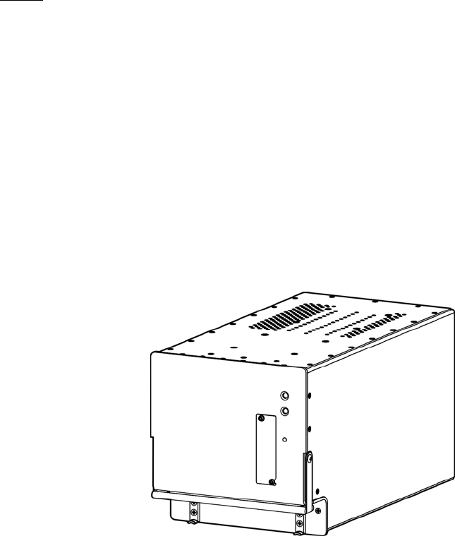
1. Illustration of Equipment
Figure INTRO-1 shows the SDU.
Figure INTRO-1 Satellite Data Unit
SYSTEM DESCRIPTION, INSTALLATION, AND MAINTENANCE MANUAL
ARINC 781-200 SDU and SCM
23-15-30 INTRO-2
DATE TBD
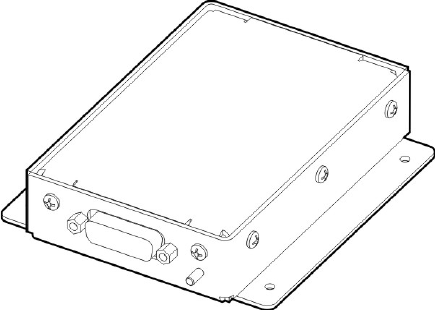
Figure INTRO-2 shows the SCM.
Figure INTRO-2 SDU Configuration Module
2. Acronyms and Abbreviations
AES Aircraft Earth Station
AMSS Aeronautical Mobile Satellite Services
AORE Atlantic Ocean Region-East
AORW Atlantic Ocean Region-West
APAC Asia-Pacific
BIT Built-In-Test
BITE Built-In-Test Equipment
BSU Beam Steering Unit
CEPT Comite Europeen des Postes et Telecommunications
CTU Cabin Telecommunications Unit
DLNA Diplexer/Low-Noise Amplifier
DITS Digital Information Transfer System
EASA European Aviation Safety Agency
EMEA Europe, Middle East, and Africa
ESD Electrostatic Discharge
FAA Federal Aviation Administration
FAR Federal Aviation Regulation
SYSTEM DESCRIPTION, INSTALLATION, AND MAINTENANCE MANUAL
ARINC 781-200 SDU and SCM
23-15-30 INTRO-3
DATE TBD
FMS Flight Management System
GES Ground Earth Station
GND Ground
HGA High Gain Antenna
HPA High Power Amplifier
ICA Instructions for Continued Airworthiness
ICAO lnternational Civil Aviation Organization
I/O Input/Output
IOR Indian Ocean Region
IRS Inertial Reference System
ISDN Integrated Services Digital Network
LES Land Earth Station
LRU Line Replaceable Unit
MCDU Multi-purpose Control Display Unit
MCU Modular Concept Unit
MES Mobile Earth Station
MHz Megahertz
MOPS Minimum Operational Performance Standards
MPU Maintenance Port Utility
ORT Owner Requirement Table
POR Pacific Ocean Region
POTS Plain Old Telephone System
RF Radio Frequency
RMA Return Material Authorization
RTN Return
Rx Receive
SATCOM Satellite Communications
SBB SwiftBroadband (Inmarsat)
SCM SDU Configuration Module
SDU Satellite Data Unit
SLU Software Logical Unit
SYSTEM DESCRIPTION, INSTALLATION, AND MAINTENANCE MANUAL
ARINC 781-200 SDU and SCM
23-15-30 INTRO-4
DATE TBD
3. Safety Advisories
Warnings, cautions, and notes in this manual provide the reader with the following information:
• A WARNING describes an operation, procedure, or condition that, if not obeyed, could
cause injury or death.
• A CAUTION describes an operation, procedure, or condition that, if not obeyed, could cause
damage to the equipment.
• A NOTE provides supplementary information or explanatory text that makes it easier to
understand and perform procedures.
All personnel who install, operate, and maintain the ARINC 781-200 SDU and SCM, and
associated test equipment must know and obey the safety precautions listed below. The
procedures provided in this manual assume that the person performing installation or
maintenance tasks is familiar with and obeys standard aviation shop and safety practices.
The general safety advisories include the following:
WARNING: THE ARINC 781-200 AVIONICS SYSTEM INCLUDES COMPONENTS THAT
RADIATE RF AND MICROWAVE EMISSIONS IN THE BANDWIDTH OF 1626.5
TO 1660.5 MHZ.
WARNING: BEFORE HANDLING ANY UNIT OR COMPONENT, GROUND THE REPAIR
OPERATOR THROUGH A CONDUCTIVE WRIST STRAP OR OTHER DEVICE
THAT USES A 470KILOHM OR 1 MEGAOHM SERIES RESISTOR TO
PREVENT INJURY.
CAUTION: TURN OFF POWER BEFORE DISCONNECTING ANY EQUIPMENT FROM
WIRING. DISCONNECTING THE EQUIPMENT WITHOUT TURNING POWER
OFF MAY CAUSE VOLTAGE TRANSIENTS THAT CAN DAMAGE THE
EQUIPMENT.
CAUTION: THIS EQUIPMENT INCLUDES ITEMS THAT ARE ELECTROSTATIC
DISCHARGE SENSITIVE (ESDS) DEVICES. ESDS DEVICES ARE SUBJECT
TO DAMAGE BY EXCESSIVE LEVELS OF VOLTAGE AND/OR CURRENT.
THE LOW-ENERGY SOURCE THAT MOST COMMONLY DESTROYS ESDS
STC Supplemental Type Certificate
Tx Transmit
USIM Universal Subscriber Identity Module
UUT Unit Under Test
VSWR Voltage Standing Wave Ratio
SYSTEM DESCRIPTION, INSTALLATION, AND MAINTENANCE MANUAL
ARINC 781-200 SDU and SCM
23-15-30 INTRO-5
DATE TBD
DEVICES IS THE HUMAN BODY, WHICH, IN CONJUNCTION WITH
NONCONDUCTIVE GARMENTS AND FLOOR COVERINGS, GENERATES
AND RETAINS STATIC ELECTRICITY. TO ADEQUATELY PROTECT ESDS
DEVICES, THE DEVICE AND EVERYTHING THAT CONTACTS IT MUST BE
BROUGHT TO GROUND POTENTIAL BY PROVIDING A CONDUCTIVE
SURFACE AND DISCHARGE PATHS. USE STANDARD INDUSTRY
PRECAUTIONS TO KEEP RISK OF DAMAGE TO A MINIMUM WHEN
TOUCHING, REMOVING, OR SERVICING THE EQUIPMENT.
SYSTEM DESCRIPTION, INSTALLATION, AND MAINTENANCE MANUAL
ARINC 781-200 SDU and SCM
23-15-30 INTRO-6
DATE TBD
Blank Page
SYSTEM DESCRIPTION, INSTALLATION, AND MAINTENANCE MANUAL
ARINC 781-200 SDU and SCM
23-15-30 1-1
DATE TBD
SYSTEM DESCRIPTION
This section includes basic information about the A781-200 system, including the following sections:
• Inmarsat System Overview
• Equipment Overview
• Equipment Specifications
• System Interfaces
• User Interfaces
• Software Description
1. Inmarsat System Overview
This section provides an overview of the Inmarsat satellite communications system and
networks.
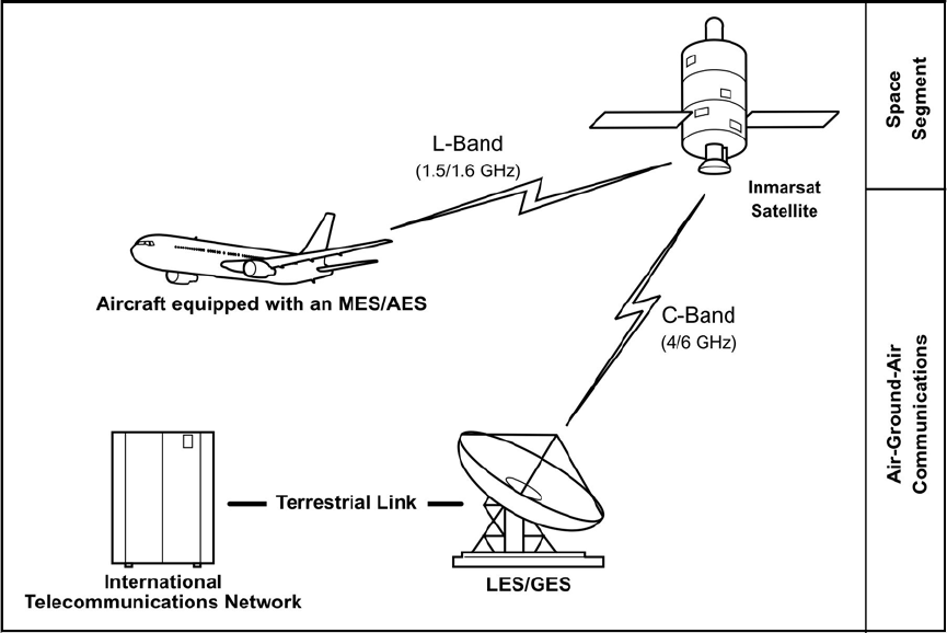
Satellite communication systems provide users with long-range voice and data communication
by accessing global satellite and ground communications networks. Satellite communication
systems include global satellite networks, Land Earth Stations (LESs), Ground Earth Stations
(GESs), Aircraft Earth Stations (AESs), and Mobile Earth Stations (MESs).
The LES/GES is the part of the satellite communication system that is on the ground. These
numerous, international stations are responsible for routing voice and data calls from the
MES/AES to their destinations around the world. The MES/AES is the part of the satellite
communication system that is on the aircraft. GES and AES are the terms associated with
Aero-H+ services. LES and MES are terms associated with other satellite communication
services.
Inmarsat is an international organization that operates and maintains multiple geostationary
satellites and satellite networks (I-3 and I-4). For more information about I-3 and I-4 satellite
beam coverage, refer to the Inmarsat website—www.inmarsat.com.
I-3 satellites provide Inmarsat services for aviation (Aero H+ and Swift 64), shipping, and
land-mobile users. The satellites connect to ground telecommunication systems through a
network of GESs. Each I-3 satellite is located over an Ocean Region (OR)—the current OR
names are:
• Atlantic Ocean Region-East (AOR-E)
• Atlantic Ocean Region-West (AOR-W)
• Indian Ocean Region (IOR)
• Pacific Ocean Region (POR)
SYSTEM DESCRIPTION, INSTALLATION, AND MAINTENANCE MANUAL
ARINC 781-200 SDU and SCM
23-15-30 1-2
DATE TBD
I-4 satellites provide worldwide SwiftBroadband (SBB service). Each I-4 satellite has 19 wide
spot beams, 228 narrow spot beams, and is capable of accommodating many separate,
simultaneous SBB sessions. The SBB service and I-4 satellites support broadband applications.
The current I-4 satellites are:
• AMERICAS
• EMEA (Europe, Middle East, and Africa)
• APAC (Asia-Pacific)
The satellite communication avionics (A781-200 system), in conjunction with an antenna
subsystem, act as an AES/MES. The combined system provides users with a data and voice
communications link to the satellite network and global telecommunications system.
Figure 1-1 illustrates a simplified satellite communications system.
Figure 1-1 Simplified Aeronautical Satellite Communications System
2. Equipment Overview
The A781-200 system, in combination with the antenna sub-system, provides
Aeronautical Mobile Satellite Services (AMSS) by facilitating airborne satellite
communications over the Inmarsat network, including the following services:
SYSTEM DESCRIPTION, INSTALLATION, AND MAINTENANCE MANUAL
ARINC 781-200 SDU and SCM
23-15-30 1-3
DATE TBD
• Classic Aero-H+—Provides packet data services at 600 bps, 1200 bps, or 10500 bps
over the PRT channel combination and half-rate circuit switched voice or data service
over the C channel.
• Swift 64—Provides packet switched Mobile Packet Data Service (MPDS) or 64kbps
circuit-switched Unrestricted Digital Information (UDI).
• SwiftBroadband (SBB)—Provides AMBE+2 voice (circuit-switched) and broadband
packet switched services. The equipment can achieve aggregate rates of 432 kbps,
but data rates may vary with network load and signal quality. The equipment can be
configured for either single or dual SBB.
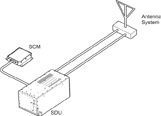
The A781-200 system consists of the Satellite Data Unit (SDU) and the Satellite Data
Unit Configuration Module (SCM).
Figure 1-2 illustrates the A781-200 system.
Figure 1-2 A781-200 Avionics System
A. SDU
The SDU is the central communications processing and control unit and largely
determines the functionality of the complete SATCOM system. It manages interfaces,
routing and priorities, and call channel establishment and tear down. The SDU provides
RF power amplification using an internal high power amplifier (HPA).
The SDU is divided into several Shop Replaceable Units (SRUs) that are electrically
connected via the backplane. Various SRUs are also connected using RF cables.
B. SCM
The SCM is an external peripheral of the SDU and provides a dedicated interface to the
SDU. It stores Secure and User ORTs (Owner Requirement Tables), a Swift 64 Forward
ID and the keys to enable either single or dual SBB capability. The SCM can
accommodate up to four Universal Subscriber Identity Modules (USIM) that store
subscriber information for the SBB network.

SYSTEM DESCRIPTION, INSTALLATION, AND MAINTENANCE MANUAL
ARINC 781-200 SDU and SCM
23-15-30 1-4
DATE TBD
By storing configuration information independent of the SDU, the SCM facilitates efficient
SDU replacement. A new SDU that replaces a faulty SDU does not require any
configuration. All configuration information is obtained from the SCM.
3. Equipment Specifications
This section includes the physical and environmental characteristics of the A781-200 SDU and
SCM.
Table 1-1 provides a summary of the physical characteristics and equipment specifications of
the SDU component.
Table 1-1 SDU Physical Characteristics and Specifications
CHARACTERISTIC SPECIFICATION
RELATED DOCUMENTS
ARINC characteristics ARINC 781-4 Mark 3Aviation Satellite
Communications System
ARINC 600 Air Transport Avionics Equipment
Interfaces
RTCA documents DO-254, Design Assurance Guidance for Airborne
Electronic Hardware
DO-178B, Software Considerations in Airborne
Systems and Equipment Certification
DO-160E, Environmental Conditions and Test
Procedures for Airborne Equipment
DO-210, Minimum Operational Performance
Standards (MOPS) for Geosynchronous Orbit
Aeronautical Mobile Satellite Services (AMSS)
Avionics
SDU SPECIFICATIONS
Physical Size
Length 37.24 cm (14.66 in)
Width 19.35 cm (7.62 in)
Height 19.93 cm (7.85 in)
Weight 11.30 kg (24.9 lbs)
Heating and Cooling
Cooling Air ARINC 600
Flow Rate 50 kg/hr 40°C (max) air
Pressure Drop 5 ± 3 mm H2O
Mounting Information 6 MCU tray as per ARINC 600

SYSTEM DESCRIPTION, INSTALLATION, AND MAINTENANCE MANUAL
ARINC 781-200 SDU and SCM
23-15-30 1-5
DATE TBD
Table 1-2 provides a summary of the physical characteristics and equipment specifications of
the SCM component.
Table 1-2 SCM Physical Characteristics and Specifications
CHARACTERISTIC SPECIFICATION
RELATED DOCUMENTS
ARINC characteristics ARINC 781 Mark 4 Aviation Satellite
Communications System
RTCA documents DO-254, Design Assurance Guidance for Airborne
Electronic Hardware
DO-160E, Environmental Conditions and Test
Procedures for Airborne Equipment
SCM SPECIFICATIONS
Physical Size
Length 11.43 cm (4.5 in)
Width 10.16 cm (4.0 in)
Height 2.54 cm (1.0 in)
Weight 0.454 kg (1.0 lbs)
Mounting Information 4 x 0.125" holes on 3.3" x 3.5" spacing, per
attachment 1-6 of ARINC 781
Electrical Interfaces
Power/Control interface as per ARINC 781
Power Requirements + 12 V ± 5% (derived from SDU)
Electrical Interfaces
Power/Control interface as per ARINC 781
Power Requirements
Input Voltage (AC) 96 to 122 V AC, 300 to 900 Hz
Power Consumption 400 VA
Table 1-1 SDU Physical Characteristics and Specifications (Continued)
CHARACTERISTIC SPECIFICATION

SYSTEM DESCRIPTION, INSTALLATION, AND MAINTENANCE MANUAL
ARINC 781-200 SDU and SCM
23-15-30 1-6
DATE TBD
Table 1-3 lists the RTCA/DO-160E environmental characteristics of the SDU and SCM.
Table 1-3 ARINC 781-200 SDU and SCM RTCA/DO-160E Environmental Characteristics
Section Environmental Condition Category
4.0 Temperature and Altitude F2
4.5.1 Ground Survival Low F2
4.5.2 Operating Low Ambient F2
4.5.3 Short Time Operating High F2
4.5.4 Operating High Ambient F2
4.5.5 In Flight Loss of Cooling F2
Ground Survival Low Temperature F2
Ground Survival High Temperature F2
4.6.1 Altitude F2
5Temperature Variation B
6Humidity B
7Operational Shock and Crash Safety B
8.5.2 Vibration Standard – Random S, Curve B
9.0 Explosive Atmosphere E
15 Magnetic Effect A
16.5.1.4 Power Input (ac) Interruptions A(WF)X
17 Voltage Spike A
18 Audio Frequency Conducted Susceptibility (ac) K(WF)
19 Induced Signal Susceptibility CW
20 Radio Frequency Susceptibility R
21 Emission of RF Energy L
22 Lightning Induced Transient Susceptibility A3E3X
24 Icing A
25 Electrostatic Discharge (ESD) A
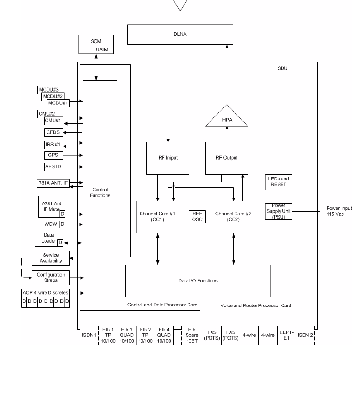
4. System Interfaces
This section describes the A781-200 system interfaces.
Figure 1-3 illustrates the block diagram of the A781-200 avionics system.
SYSTEM DESCRIPTION, INSTALLATION, AND MAINTENANCE MANUAL
ARINC 781-200 SDU and SCM
23-15-30 1-7
DATE TBD
Figure 1-3 A781-200 Avionics System Block Diagram
NOTE: On the aircraft only the Ethernet 3, POTS, 4-Wire and CEPT-E1 ports are
supported.
A. SDU
The SDU is divided into the following LRUs:
• Channel Cards (2)
• Control and Data Processor Card
• Voice and Router Processor Card
• Power Amplifier
• ARINC Backplane
• DIN Backplane
• 10 MHz Oven Controlled Crystal Oscillator
• Power Supply

SYSTEM DESCRIPTION, INSTALLATION, AND MAINTENANCE MANUAL
ARINC 781-200 SDU and SCM
23-15-30 1-8
DATE TBD
The major interfaces of the SDU are listed in Table 1-4.
B. SCM
The SCM does not provide any interfaces other than a dedicated interface to the SDU.
The SCM is powered by the SDU.
5. User Interfaces
This section describes the A781-200 SDU interfaces that enable users to access Inmarsat
services and monitor the operation of the A781-200 system.
NOTE: There are no user interface associated with the SCM.
A. MCDU
The MCDU is a device that uses an ARINC 429 interface per ARINC 739, which lets you
communicate with individual instruments on an aircraft, including the Flight Management
System (FMS), very high frequency (VHF) radio, and the SDU.
The SDU supports three MCDUs.
B. 4-Wire Audio
The SDU supports two 4-wire audio interfaces.
C. Ethernet
The SDU supports one Ethernet data interface.
Table 1-4 SDU System Interfaces
System Interface Description
ACU/BSU (x1) Antenna Control Unit/Beam Steering Unit
MCDU (x3) Multi-Purpose Control and Display Unit
ACARS CMU (x2) Aircraft Communication Addressing and Reporting System
Communication Management Unit
IRS (x2)/GPS (x1) Inertial Reference System/Global Positioning System
SCM (x1) SDU Configuration Module
AES ID (x1) Aircraft Earth Station Identification
Servicing Front Panel Accessible Service Port for data log retrieval
Button Initiated Self-Test
RF Transmit/receive to the DLNA
Antenna subsystem ARINC 781 Antenna Subsystem
Miscellaneous ARINC discrete input, outputs, and configuration straps

SYSTEM DESCRIPTION, INSTALLATION, AND MAINTENANCE MANUAL
ARINC 781-200 SDU and SCM
23-15-30 1-9
DATE TBD
D. POTS
The SDU supports two POTS interfaces.
E. CEPT-E1
The SDU supports one CEPT-E1 interface.
F. ISDN
Two ISDN interfaces are currently not supported.
G. Maintenance Port
The SDU is equipped with a maintenance port, located on its front panel. The
maintenance port provides the physical connection to a password-protected
Maintenance Port Utility (MPU) that provides a system interface for users or service
personnel who need to monitor or troubleshoot the system.
For more information on configuring the maintenance port, refer to "Connecting to the
MPU" on page 4-2.
H. LEDs
The front panel of the SDU has two LEDs to indicate unit status:
• One green LED labelled Power
• One red LED labelled Fault
Table 1-5 provides information about the LED signals.
Table 1-5 SDU LED Status
Power LED Status Fault LED Status Description of SDU Status
LED is on LED is off No fault detected
LED is on LED is steadily on as long as
the fault exists LRU fault detected
LED is on Flashing at 1 Hz with a 50%
duty cycle while the fault
exists
System fault detected but not isolated
to the LRU
Alternating flashing of Power and Fault LEDs Self-test in progress
I. Self-Test Button
The front panel of the SDU has a recessed button labelled Test:
• To reset the unit, press and hold the Test button for at least 5 seconds
• To initiate self-test (when no LEDs are flashing), momentarily press the Test button
• When the self test completes (power on or user initiated) the Power LED will illuminate
steady for a period of 60 seconds and then it will deactivate for the duration of
operation.

SYSTEM DESCRIPTION, INSTALLATION, AND MAINTENANCE MANUAL
ARINC 781-200 SDU and SCM
23-15-30 1-10
DATE TBD
NOTE: During initial power-up or self-test execution, a momentary press of the
self-test button is ignored.
The LEDs indicate the results of the self-test. Table 1-5 provides information about the
meaning of LED signals.
6. Software Description
All operating software meets RTCA/DO-178B Level D requirements.
The SCM does not contain any software. Only configuration parameters are stored in the SCM.
The SDU software is not partitioned. The software is modular and modules run on individual
Software Logical Units (SLUs) within the SDU:
• Each channel card has a single SLU
• Control and Data Processor card has a Control SLU and a Data SLU
• Voice and Router card has a Voice SLU and a Router SLU
SYSTEM DESCRIPTION, INSTALLATION, AND MAINTENANCE MANUAL
ARINC 781-200 SDU and SCM
23-15-30 2-1
DATE TBD
SYSTEM OPERATION
The SDU is an integral component in an AES. Together with the SCM, DLNA, Antenna, and HGA
subsystem, it provides AMSS by facilitating airborne satellite communication services over the
Inmarsat network. These services comprise Classic Aero-H+, Swift 64, and SwiftBroadband (SBB).
The SCM is a dedicated peripheral of the SDU and stores aircraft specific installation configuration
critical to the operation of the AES.
This section provides basic information on using the A781-200 system.
1. Registering and Activating Terminals
Registering and activating the A781-200 system has the following steps:
• Obtaining ICAO Addresses
• Choosing Service Providers
• Registering Terminals
A. Obtaining ICAO Addresses
Obtain your ICAO address from your local aeronautical authority. Your service provider
will require this address when you register.
B. Choosing Service Providers
Contact Inmarsat for an up-to-date list of Inmarsat Service Providers using the following
contact information:
Inmarsat
99 City Road, London
EC1Y 1AX
Tel: +44 20 7728 1000
Fax: +44 20 728 1044
Customer Care
Tel: +44 20 7728 1777
Fax: +44 20 7728 1142
Email: customer_care@inmarsat.com
Web address: www.inmarsat.com
C. Registering Terminals
Contact your Inmarsat service provider and ask for a registration for service activation of
Aircraft Earth Station form. With this form, you can register for SBB and Aero H+ services.
The services available depend on your service provider.
SYSTEM DESCRIPTION, INSTALLATION, AND MAINTENANCE MANUAL
ARINC 781-200 SDU and SCM
23-15-30 2-2
DATE TBD
To complete the registration form you need the following information:
• Customer information (address and contact information)
• Service provider details (obtained from your ISP)
• System and terminal information (terminal type, manufacturer, model number, serial
number of terminal)
• ICAO 24 bit technical address for Aero H+ services
• IMEI and IMSI (printed on the SCM label) for SBB services
• Aircraft information (tail number, fuselage/airframe number, manufacturer and model,
and country of registration)
• List of services required (for example, Aero H+ data-2, SBB PS and SBB CS services)
2. Using the A781-200 System
This section describes how to perform the following tasks:
• Operating the MCDU
• Logging On and Off
• Enabling and Disabling the Cabin Telecommunications Unit (CTU)
• Accepting and Making Calls in the Cockpit
• Viewing BITE Information
A. Operating the MCDU
This section provides information about the MCDU screen and the keyboard.
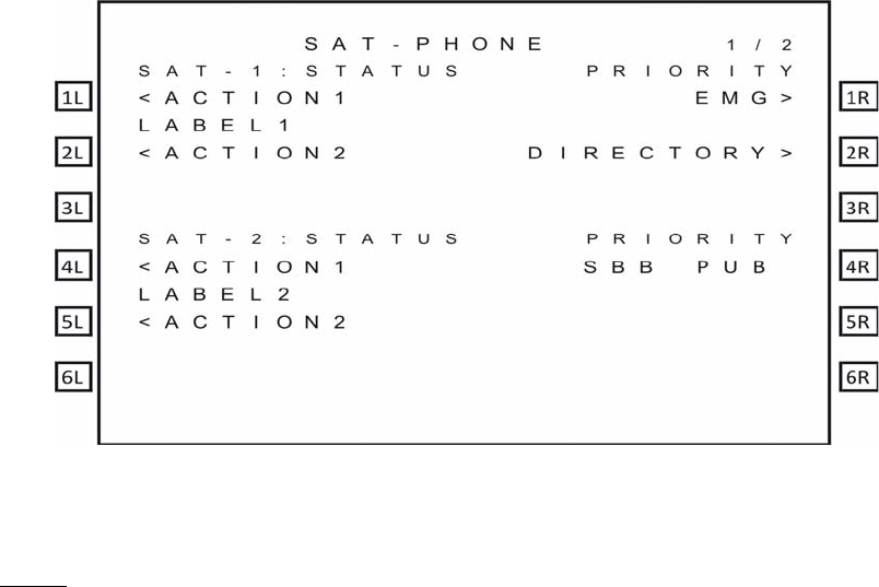
(1) Screen
The MCDU displays all data on the screen, as shown in Figure 2-1.
SYSTEM DESCRIPTION, INSTALLATION, AND MAINTENANCE MANUAL
ARINC 781-200 SDU and SCM
23-15-30 2-3
DATE TBD
Figure 2-1 MCDU Screen
NOTE: The SAT PHONE 1/2 menu shown in Figure 2-1 is an example where classic (SAT-1)
and SBB (SAT-2) cockpit calls are supported. Depending on the secure ORT
parameter settings, the prompts "SAT-1" and "SAT-2" can be replaced to display any
message limited to five characters.
The top of the screen displays the title of the menu on the screen. The bottom of the
screen (Line 14) is the scratchpad that displays information that you enter on the
keyboard.
The MCDU has six buttons on each side of the screen that activate MCDU functions.
Figure 2-1 displays these buttons on the left and right sides of the screen. When the
functions corresponding to a button are available, the function is displayed beside
the button.
Other lines on the MCDU screen display information relevant to the function or status
of the A781-200 system.
(2) Keyboard
The MCDU’s keyboard includes a set of numeric keys and a set of alphabetic keys,
both of which you can use to enter data into the MCDU.
The keyboard may include preset keys, such as the following:
•The IDX or MAIN MENU key: this key returns you to the MCDU’s main menu.
•The CLR key: this key clears any text you type into the scratchpad.
•The NEXT PAGE key: this key brings up the next page of a menu if one is
available.
•The PREV PAGE key: this key brings up the previous page of a menu if one is
available.
SYSTEM DESCRIPTION, INSTALLATION, AND MAINTENANCE MANUAL
ARINC 781-200 SDU and SCM
23-15-30 2-4
DATE TBD
(3) Special Symbols
Because of space constraints on the screen, the MCDU uses a number of special
symbols to indicate actions:
• < and > appear at the far left or right to indicate that another menu page is
available in that direction or that a function is available for that label.
• NUMBER/NUMBER appears to tell you which page out of how many pages you
are viewing. For example, 1/3 would appear when you are on page 1 of 3 pages
in total.
(4) Navigating the MCDU
The MCDU includes a number of menus, as shown in Figure 2-2.

SYSTEM DESCRIPTION, INSTALLATION, AND MAINTENANCE MANUAL
ARINC 781-200 SDU and SCM
23-15-30 2-5
DATE TBD
Figure 2-2 A781-200 MCDU Menu Structure
B. Logging On and Off
Using the MCDU, you can log on to the satellite network manually or automatically:
• Manual Logon—constrains the logon to use a satellite that you select
• Automatic Logon—logs on using the best available satellite as defined by the ORT
If specified in the ORT, the initial system logon happens immediately after the
A781-200 system powers up, with no MCDU input required. If the ORT is not configured
as such, you must initiate the logon from the MCDU (MANUAL LOG-ON or AUTO
LOG-ON command). For more information, see "ORT Overview" on page 3-8.
SYSTEM DESCRIPTION, INSTALLATION, AND MAINTENANCE MANUAL
ARINC 781-200 SDU and SCM
23-15-30 2-6
DATE TBD
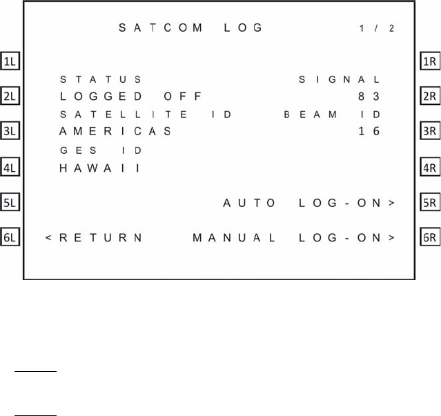
You can watch the progress of the logon on the SATCOM LOG 1/2 menu, or simply wait
until the prompt on the SAT-PHONE 1/2 menu indicates the service is available for use.
(1) Logging On Automatically
When you initiate an automatic logon, the system selects a satellite and GES based
on the preferences specified in the ORT.
To log on automatically:
1. On the SAT-PHONE 1/2 menu, press the button next to LOG.
The SATCOM LOG menu appears.
2. On the SATCOM LOG menu, press the button next to AUTO LOG-ON.
The MCDU returns to the SAT-PHONE 1/2 menu and the CLSSC and SBB
channels are updated with READY status after the logon completes.
NOTE: The MCDU does not display the AUTO LOG-ON and MANUAL LOG-ON
functions when the A781-200 system is already logged on.
NOTE: On the SAT-PHONE 1/2 menu, CLSSC shows the Classic Aero channel
status and SBB shows the SBB channel status. The A781-200 system
logs on the Classic Aero channels first, and then logs on the SBB
channels.
(2) Logging On Manually
To log on manually, you must select a satellite and GES.
To log on manually:
1. On the SAT-PHONE 1/2 menu, press the button next to LOG.
The SATCOM LOG menu appears.
2. Press the button next to SATELLITE ID until the MCDU screen shows the
satellite ID to which you want the A781-200 system to log on.

SYSTEM DESCRIPTION, INSTALLATION, AND MAINTENANCE MANUAL
ARINC 781-200 SDU and SCM
23-15-30 2-7
DATE TBD
3. Press the button next to GES ID until the MCDU screen shows the GES to which
you want the A781-200 system to log on.
4. On the SATCOM LOG menu, press the button next to MANUAL LOG-ON.
The MCDU returns to the SAT-PHONE 1/2 menu and updates the SAT-L and
SAT-R channels with READY status after the log on completes.
NOTE: SAT-L shows the Classic Aero channel status and SAT-R shows the SBB
channel status. The A781-200 system logs on the Classic Aero channels
first, and then searches for SBB or Swift 64 services on the satellite
determined by the Classic Aero log-on.
(3) Logging Off Classic Aero Services
WARNING: This option does not log off SBB or Swift 64 services. If either of these
services is running, they will continue to run and potential charges could be
made to the cabin. To completely log off, power down the A781-200 system.
To log off:
1. On the SAT-PHONE 1/2 menu, press the button next to LOG.
The SATCOM LOG menu appears.
2. On the SATCOM LOG menu, press the button next to LOG-OFF.
The A781-200 system logs off the satellite network.
(4) Viewing Log Status
The log status defines whether the A781-200 system is logged on or logged off. Valid
values are shown in Table 2-1.
Table 2-1 A781-200 System Log Status
Log Status Description
SAFE MODE Configuration error detected
HSR NOT READY High stability oscillator is in a warming condition
ANT NOT READY Antenna is reporting test state
AES ID NOT READY Displayed until a non-zero ICAO address is present
NAV DATA UNAVAIL Insufficient navigation data available
CC NOT READY Channel card has not fully booted
LOGGED OFF A781-200 system not logged on to the satellite network.
Awaiting input from the user
TUNING TO SAT Tuning and scanning for reception from the selected
satellite
DET SYS TABLE Updating the Satellite table
SPOT BEAM SEARCH Selecting the optimal spot beam
WAIT LOGON CONF Awaiting the logon confirmation from the satellite
WAIT LOGON ACK Awaiting for logon acknowledge from the GES
LOGGED ON Successfully logged on to GES
SYSTEM DESCRIPTION, INSTALLATION, AND MAINTENANCE MANUAL
ARINC 781-200 SDU and SCM
23-15-30 2-8
DATE TBD
To view log status:
1. On the SAT-PHONE 1/2 menu, press the button next to LOG.
The SATCOM LOG menu appears.
2. The log status appears on the line below STATUS.
C. Enabling and Disabling the Cabin Telecommunications Unit (CTU)
To use the CTU, the CEPT-E1 interface needs to be enabled in the Secure ORT. See
"Owners Requirements Table (ORT)" on page 3-8.
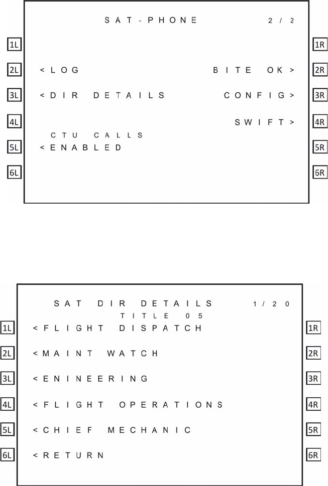
You can enable and disable the calls to and from the CTU from the SAT-PHONE 2/2 menu.
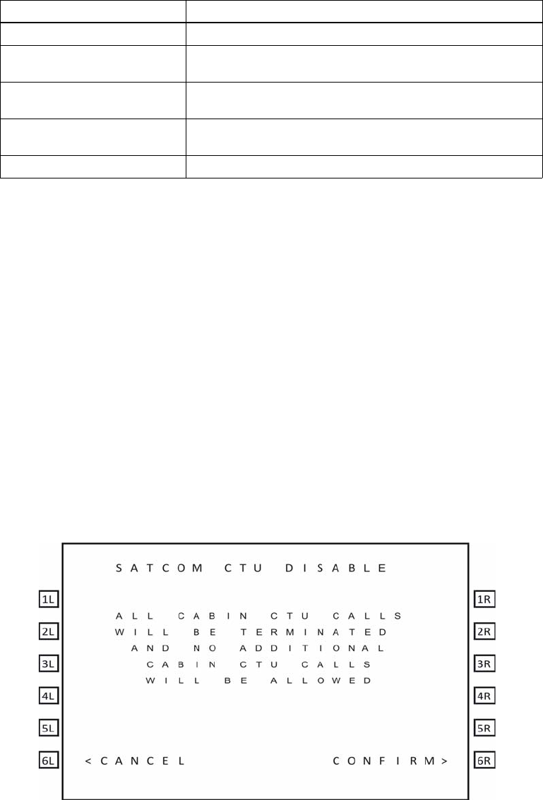
(1) Disabling CTU calls
To disable CTU calls:
1. On the SAT-PHONE 2/2 menu, press the button next to ENABLED.
The CTU DISABLE menu appears.
2. To disable all CTU calls, press the button next to CONFIRM.
REJECT-TEMPORARY Logon rejected by the GES, but the condition is temporary
REJECT-PERMANENT Logon rejected by the GES, and the condition is
permanent
REJECT-INV PARAM Logon rejected by the GES due to invalid parameters, and
the condition is permanent
REJECT-AES INVAL ICAO address was not accepted by the GES, the
condition is permanent
LOGGING OFF Starting the logoff process
Table 2-1 A781-200 System Log Status (Continued)
Log Status Description
SYSTEM DESCRIPTION, INSTALLATION, AND MAINTENANCE MANUAL
ARINC 781-200 SDU and SCM
23-15-30 2-9
DATE TBD
(2) Enabling CTU calls
To enable CTU calls:
• On the SAT-PHONE 2/2 menu, press the button next to DISABLED.
The MCDU displays ENABLED under CTU CALLS.
D. Accepting and Making Calls in the Cockpit
You can make air- to-ground and accept ground-to-air voice calls using the A781-200
system, the MCDU, the Audio Control Panel (ACP), and a 4-wire cockpit headset.
The 4-wire cockpit headset supports Push to Talk (PTT) mode. Push to Talk mode mimics
the way an HF radio functions. The user's voice is only transmitted when the 'Mic On'
input is asserted i.e. pushed.
(1) Making Cockpit Calls
You can manually dial calls or dial previously saved telephone numbers from the
MCDU’s telephone directory.
When the SDU cannot complete a call, the MCDU displays CALL FAIL.The call and
event logs provide information about the cause of the call failure. Call and event logs
are accessible to avionics technicians through the maintenance port of the SDU.
(a) Making Calls from the Scratchpad
A call can only be initiated using the buttons on the MCDU.
To make a call:
1. On the MCDU main menu, press the button next to SAT.
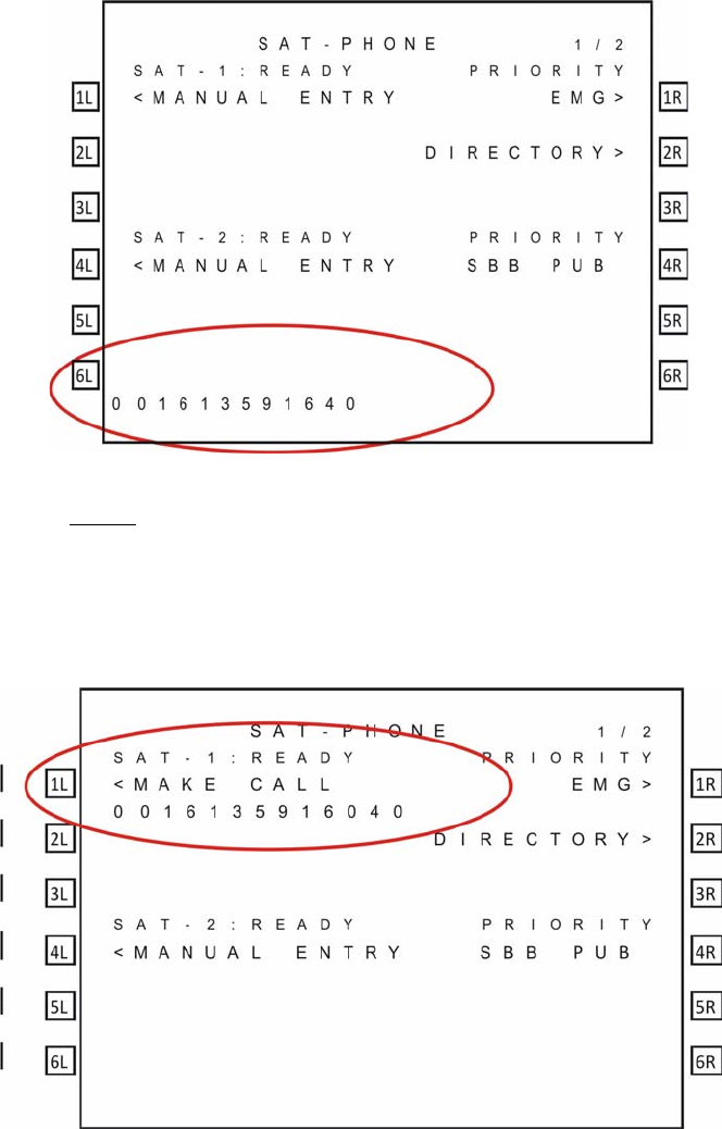
2. Enter a number in the MCDU scratchpad using the following pattern.
00+CC+NNN+NUMBER
00 is the access code for international calls, CC is the country code, and
NNN is the city or area code.
• No hyphens are needed when entering the number in the MCDU scratch
pad.
• 18 is the maximum number of characters that you can enter.
• To delete an incorrect character, press CLR on the sratchpad.
The number appears at the bottom of the MCDU screen and MANUAL
ENTRY appears under the channel label.
SYSTEM DESCRIPTION, INSTALLATION, AND MAINTENANCE MANUAL
ARINC 781-200 SDU and SCM
23-15-30 2-10
DATE TBD
3. Press the button next to MANUAL ENTRY.
NOTE: If an entry has MANUAL ENTRY under the SAT-1 label, that entry
can be dialed on Classic Aero channels. If an entry has MANUAL
ENTRY under the SAT-2, that entry can be dialed on SBB channels.
MAKE CALL and the number appear under the channel label.
4. To set the priority, press the button next to PRIORITY.
Note: You can only set the priority for a Classic call. All calls made over SBB
are public priority.
SYSTEM DESCRIPTION, INSTALLATION, AND MAINTENANCE MANUAL
ARINC 781-200 SDU and SCM
23-15-30 2-11
DATE TBD
5. On the MCDU, press the button next to MAKE CALL.
The channel status displays DIALING, RINGING and then ANSWERED
when connected.
(b) Making Calls from the Telephone Directory
You can make voice calls from the numbers you have saved in the MCDU’s
telephone directory. Numbers can be saved in the telephone directory using the
MCDU or the ORT. For more information on the ORT, see "ORT Overview" on
page 3-8.
To make a call from the telephone directory:
1. On the MCDU main menu, press the button next to SAT.
2. On the MCDU keyboard, press the NEXT PAGE key to advance to the
second page of the SAT-PHONE menu, and then press the button next to
DIRECTORY.
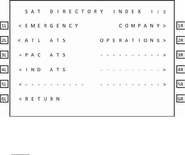
The SAT DIRECTORY INDEX menu appears.
3. To access phone numbers in a directory, press the button next to a directory
name.
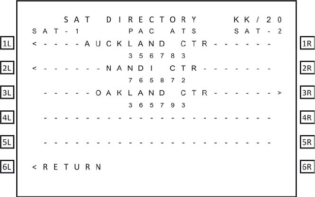
The SAT DIRECTORY menu appears.
NOTE: If an entry has the < symbol in the SAT-1 column, that entry can
be dialed on Classic Aero channels. If an entry has the > symbol in
the SAT-2 column, that entry can be dialed on SBB channels. If
there is no symbol, the entry cannot be dialed on that channel.
SYSTEM DESCRIPTION, INSTALLATION, AND MAINTENANCE MANUAL
ARINC 781-200 SDU and SCM
23-15-30 2-12
DATE TBD
4. Press the button to the left or right of the number you wish to dial.
• Pressing the left button loads the number on the Classic Aero channel
• Pressing the right button loads the number on the SwiftBroadband
channel.
The MCDU returns to page one of the SAT-PHONE menu and the number
is displayed under the selected channel.
5. To set the priority, press the button next to PRIORITY.
Note: You can only set the priority for a Classic call. All calls made over SBB
are public priority.
6. Press the button next to MAKE CALL.
The channel status displays DIALING, RINGING and then ANSWERED
when connected.
(c) Answering Calls
To answer a call:
• On the ACP, transition the MIC ON discrete from ON HOOK to OFF HOOK.
OR
On the MCDU, press the button next to ANSWER to answer the call or press
the button next to REJECT to reject the call.
(d) Ending Calls
To end a call:
• On the MCDU on the SAT-PHONE 1/2 menu, press the button next to END
CALL
OR
On the ACP, assert the Place/End switch.

SYSTEM DESCRIPTION, INSTALLATION, AND MAINTENANCE MANUAL
ARINC 781-200 SDU and SCM
23-15-30 2-13
DATE TBD
(2) Call Priority and call Pre-emption
The A781-200 system has four priority settings for calls:
• 1 Emergency
• 2 High
•3 Low
• 4 Public
(a) Setting the Call Priority
You can set the priority for an air-to-ground 4-wire Classic call before making the
call.
This priority setting allows for preemption of existing lower priority cockpit Aero
H+ calls if insufficient satellite resources exist to establish an independent call,
and for preemption of calls and services within the cabin.
If the 4-wire Classic call is the same priority as an existing call, the established
call will be retained and the new call will be queued.
Cockpit calls over SBB are Public priority calls. You can not change the priority.
All calls made from the interfaces other than the cockpit 4-wire phones or ACARS
CMU are Public priority calls.
(b) Receiving a Priority Call
If a cockpit call is in progress and a higher priority ground-to-air call is received,
the higher priority incoming call will preempt the existing call. The preemption is
automatic, and the caller in the cockpit has no option to choose between calls.
(c) Pre-empting Calls
You can preempt an existing priority 4 cabin call with a priority 4 cockpit call.
• To preempt a call, on the SAT-PHONE 1/2 menu press the button next
to PREEMPT.
• To QUEUE a call, on the SAT-PHONE 1/2 menu press the button next
to QUEUE.
• To remove a call from the QUEUE, on the SAT-PHONE 1/2 menu press
the button next to END QUEUE.
(3) Saving Telephone Numbers in the Telephone Directory
You can save telephone numbers to the MCDU’s telephone directory to use later,
and you can dial telephone numbers from the telephone directory.
NOTE: Saving telephone numbers in the directory may be inhibited by ORT options.
SYSTEM DESCRIPTION, INSTALLATION, AND MAINTENANCE MANUAL
ARINC 781-200 SDU and SCM
23-15-30 2-14
DATE TBD
To save telephone numbers to the telephone directory:
1. Navigate to the SAT-PHONE 2/2 menu and press the button next to DIR
DETAILS.
The SAT DIR DETAILS menu appears and shows directory page 1. There
are 20 phone directories with five phone number entries available in each
directory.
2. Use NEXT PAGE and PREV PAGE to navigate to the directory in which you
want to add or modify a phone number entry.
3. To modify an entry, press the button next to the entry. To add a new entry
press the button next to an empty line.

SYSTEM DESCRIPTION, INSTALLATION, AND MAINTENANCE MANUAL
ARINC 781-200 SDU and SCM
23-15-30 2-15
DATE TBD
4. Type the name associated with the telephone number in the scratchpad and
then press the button next to the name field on the MCDU screen.
• The maximum number of characters for a name is 14.
5. Type the phone number in the scratchpad using the following pattern.
00CC-NNN-NUMBER.
00 is the access code for international calls, CC is the country code, and NNN
is the city or area code.
• The maximum number of characters for a number is 18 including hyphens.
• Hypens are not necessary. If you wish to use hypens press the +/- key on
the scratchpad.
6. Press the button next to the phone number field on the MCDU screen.
7. Press the button next to PRIORITY to select a priority for the phone number.
8. To save the entry, press the button next to STORE. To cancel the new entry,
press the button next to CANCEL.
9. Press the button next to CONFIRM.
The entry is saved.
NOTE: You can protect directory entries using the Phonebook ORT
parameter. If an entry is protected, it cannot be modified or deleted.
For more information about the Phonebook ORT parameter, refer
to "ORT Overview" on page 3-8.
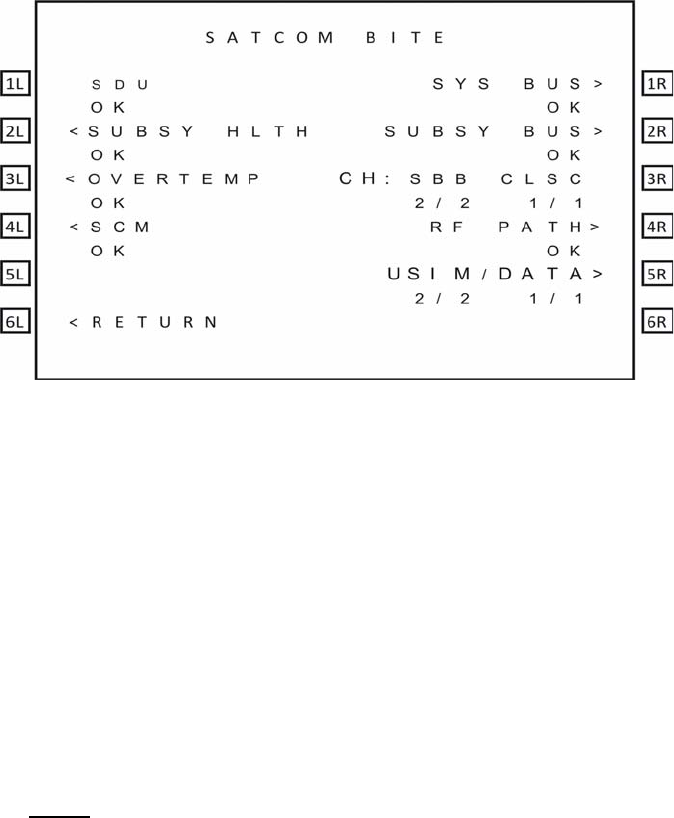
E. Viewing BITE Information
From the SATCOM BITE menu, you can view BITE information to determine subsystem
health.
To view BITE information:
1. On the MCDU main menu, press the button next to SAT.
2. On the MCDU keyboard, press the NEXT PAGE key to advance to the second
page of the SAT-PHONE menu, and then press the button next to SATCOM
BITE.
The SATCOM BITE menu appears.
SYSTEM DESCRIPTION, INSTALLATION, AND MAINTENANCE MANUAL
ARINC 781-200 SDU and SCM
23-15-30 2-16
DATE TBD
You can view the following information from this screen:
• SDU status on the line below SDU
• Overall health of all subsystem components (SCM, DLNA, and HGA) on the line
below SUBSY HLTH
• Thermal status of the SDU and HGA on the line below OVERTEMP
• SCM health on the line below SCM
• Peripheral LRU bus status on the line below SYS BUS
• Subsystem bus status on the line below SUBSY BUS
• The number of functioning SBB channels and Classic channels below CH-SBB
CLSC
• RF path status on the line below RF PATH
• USIM and data bus status on the line below USIM/DATA
NOTE: Valid values for status are OK and FAIL. If the status of a subsystem is
FAIL, press the button next to the subsystem to view the details.
To view more information about the health of a particular subsystem, press the button
next to the name of the subsystem. For more information about the various MCDU menu
screens, see "Troubleshooting and Fault Isolation" on page 4-7.
3. Channel Status and System Configuration
A. SBB Status
Depending on the SCM installed with the SDU, the A781-200 system can support single
SBB or dual SBB.
In single SBB mode, the SDU supports up to 2 simultaneous voice calls (one on classic
and one on SBB) on the CEPT-E1 interface. In this mode, the SBB menu has one page.
In dual SBB mode, the SDU supports up to 3 simultaneous voice calls (one on classic
and two on SBB) on the CEPT-E1 interface. In this mode, the SBB menu has two pages.
SYSTEM DESCRIPTION, INSTALLATION, AND MAINTENANCE MANUAL
ARINC 781-200 SDU and SCM
23-15-30 2-17
DATE TBD
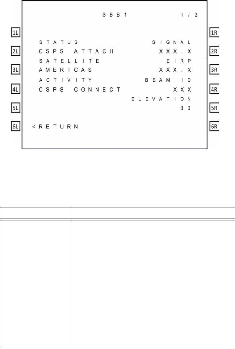
As shown in Figure 2-3, the SBB1 menu provides information about the status of the SBB
service.
Figure 2-3 SBB menu
Table 2-2 describes the information available in the SBB menu.
Table 2-2 SBB Menu
Label Description
Status The status of the SBB channel. Possible values are:
• SAFE MODE—configuration error detected
• HSR NOT READY—high stability oscillator is warming
• USIM WARMING—USIM is warming
• NOT READY—channel card has not yet started
registration, and may be waiting on the Classic card
• SEARCHING—listening for satellite signals
• ATTACHING—satellite identified and attach has begun
• CS ATTACH—attach complete, circuit-switch granted
• PS ATTACH—attach complete, packet-switch granted
• CSPS ATTACH—attach complete, circuit-switch and
packet-switch granted
• ATTACH-FAIL-###—### is the 3GPP cause code
• NO SERVICE—selected satellite does not support SBB

SYSTEM DESCRIPTION, INSTALLATION, AND MAINTENANCE MANUAL
ARINC 781-200 SDU and SCM
23-15-30 2-18
DATE TBD
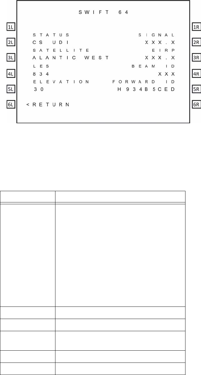
B. Swift 64
The A781-200 system can be configured to support Swift 64 by the aircraft manufacturer
at the time of installation. When the A781-200 system is configured in SWIFT 64 mode,
SBB is not supported.
When configured in Swift 64 mode, calls can only be made using Classic services.
Swift 64 can support either packet switched MPDS or 64kbps circuit-switched UDI data
services.
As shown in Figure 2-4, the Swift 64 menu provides information about the status of the
Swift 64 service.
Satellite The selected ocean region.
Activity The activity status of the SBB service. Possible values are:
• CS CONNECT—Circuit Switched services in use
• PS CONNECT—Packet Switched services in use
• CSPS CONNECT—Circuit Switched services and Packet
Switched services in use
• NONE —No services in use.
Signal The current signal quality.
EIRP The EIRP setting of the channel.
Beam ID The current beam ID for the service.
Elevation The computed elevation angle for the antenna pointing
vector.
Table 2-2 SBB Menu
Label Description
SYSTEM DESCRIPTION, INSTALLATION, AND MAINTENANCE MANUAL
ARINC 781-200 SDU and SCM
23-15-30 2-19
DATE TBD
Figure 2-4 Swift 64 Menu
Table 2-3 describes the information available in the Swift 64 menu.
Table 2-3 Swift 64 Menu
Label Description
Status The status of the Swift 64 channel. Possible
values are:
• CS UDI—Circuit Switched Unrestricted
Digital Information
•MPDS—Mobile Packet Data Service
• NO SERVICE—selected satellite does not
support Swift 64
•SEARCHING—listening for satellite signals
• READY—channel card is ready
• NOT READY—channel card has not yet
started registration, and may be waiting on
the Classic card
Satellite The selected ocean region.
LES Land Earth Station ID
Elevation The computed elevation angle for the antenna
pointing vector.
Signal The current signal quality.
EIRP The EIRP setting of the channel.
SYSTEM DESCRIPTION, INSTALLATION, AND MAINTENANCE MANUAL
ARINC 781-200 SDU and SCM
23-15-30 2-20
DATE TBD
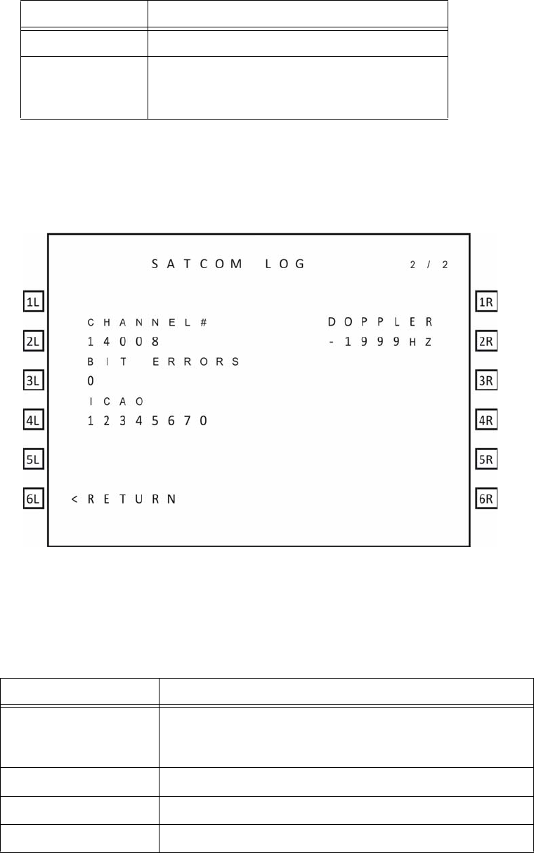
C. Channel Information and Bit Errors
As shown in Figure 2-5, the SATCOM LOG 2 menu provides information about the current
channel and the bit error rate.
Figure 2-5 SATCOM LOG 2 menu
Table 2-4 SATCOM LOG 2 Menu
Label Description
Channel # Channel number representation of the P channel,
displayed only when the SDU is logged on, otherwise the
display is blank.
Bit Errors The raw bit error rate.
ICAO The current ICAO address.
Doppler The doppler correction.
Table 2-4 describes the information available in the SATCOM LOG 2 menu.
Beam ID The current beam ID for the service.
Forward ID Swift 64 forward ID which the A781-200
system uses to access Inmarsat Swift 64
services.
Table 2-3 Swift 64 Menu
Label Description
SYSTEM DESCRIPTION, INSTALLATION, AND MAINTENANCE MANUAL
ARINC 781-200 SDU and SCM
23-15-30 2-21
DATE TBD
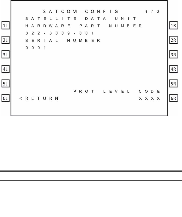
D. System Part Numbers
As shown in Figure 2-6, the SATCOM CONFIG 1 menu provides the hardware part
numbers of the SDU and the SCM.
Figure 2-6 SATCOM CONFIG 1 menu
Table 2-5 SATCOM CONFIG 1 Menu
Label Description
Hardware Part Number Part number of the A781-200 SDU.
Serial Number Serial number of the A781-200 SDU.
PROT Level Code This code is displayed if the SATCOM CONFIG menu is
accessed from the In-Flight menus. It allows access to the
Maintenance Mode MCDU menus. Contact RCI Product
Support for the PROT level code.
Table 2-5 describes the information available in the SATCOM CONFIG 1 menu.
As shown in Figure 2-7, the SATCOM CONFIG 2 menu provides the software part
numbers of the equipment in the A781-200 system.
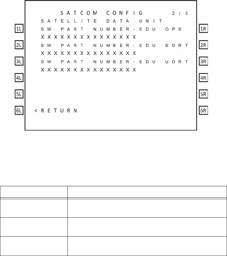
SYSTEM DESCRIPTION, INSTALLATION, AND MAINTENANCE MANUAL
ARINC 781-200 SDU and SCM
23-15-30 2-22
DATE TBD
Figure 2-7 SATCOM CONFIG 2 menu
Table 2-6 SATCOM CONFIG 2 Menu
Label Description
SW Part Number SDU
OPS Software part number of the operational software in the
A781-200 SDU.
SW Part Number SDU
SORTSoftware part number of the Secure ORT.
SW Part Number SDU
UORTSoftware part number of the User ORT.
Table 2-6 describes the information available in the SATCOM CONFIG 2 menu.
As shown in Figure 2-8, the SATCOM CONFIG 3 menu provides the software and
hardware part numbers of the antenna in the A781-200 system.
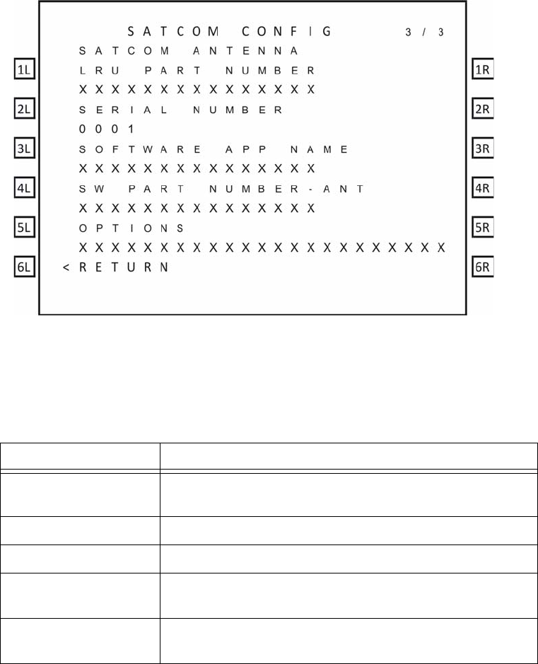
SYSTEM DESCRIPTION, INSTALLATION, AND MAINTENANCE MANUAL
ARINC 781-200 SDU and SCM
23-15-30 2-23
DATE TBD
Figure 2-8 SATCOM CONFIG 3 menu
Table 2-7 SATCOM CONFIG 3 Menu
Label Description
SATCOM Antenna
LRU Part Number Hardware part number of the antenna in the A781-200
system.
Serial Number Serial number of the antenna in the A781-200 system.
Software App Name The reported software application name.
SW Part Number - ANT Software part number of the antenna in the A781-200
system.
Options The MCDU displays the optional information field of the
configuration reporting message.
Table 2-7 describes the information available in the SATCOM CONFIG 3 menu.
4. Maintenance Mode
The maintenance menus of the MCDU provide the same configuration and BITE information
available in In-Flight mode, and provide access to the PIM test, audio configuration, and other
options and parameters.
Maintenance mode includes a number of MCDU menus, as shown in Figure 2-9.
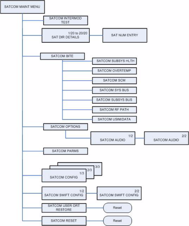
SYSTEM DESCRIPTION, INSTALLATION, AND MAINTENANCE MANUAL
ARINC 781-200 SDU and SCM
23-15-30 2-24
DATE TBD
Figure 2-9 Maintenance Mode MDCU Menu Structure
A. Accessing Maintenance Mode
You can only access the MCDU maintenance menus when the plane is on the ground
and classic services are logged off.
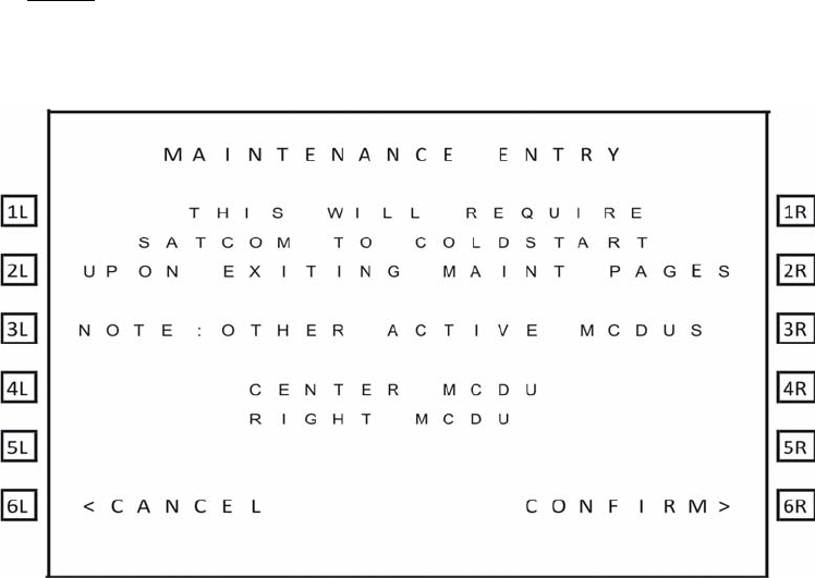
SYSTEM DESCRIPTION, INSTALLATION, AND MAINTENANCE MANUAL
ARINC 781-200 SDU and SCM
23-15-30 2-25
DATE TBD
To access the maintenance menus:
1. In the MCDU CONFIG 1/4 menu, type the protection level code in the scratchpad,
and press the button next PROT LEVEL CODE.
NOTE: Contact RCI product support for the PROT level code.
The MCDU displays the MAINTENANCE ENTRY page.
2. To enter Maintenance Mode, press the button next to CONFIRM.
The SATCOM MAINT MENU appears.
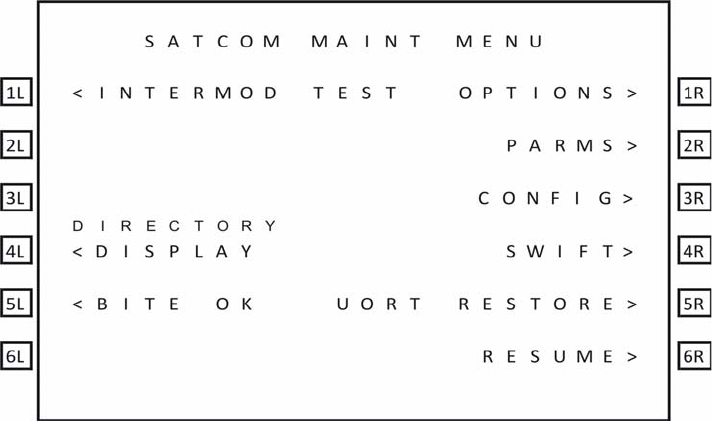
SYSTEM DESCRIPTION, INSTALLATION, AND MAINTENANCE MANUAL
ARINC 781-200 SDU and SCM
23-15-30 2-26
DATE TBD
B. Viewing BITE Information
The BITE information available in maintenance mode is the same as the BITE information
available in In-Flight mode. For information about the BITE menus, see "Viewing BITE
Information" on page 2-15.
C. Starting the Intermod Test
For information and instructions about running the PIM test, see "Passive Intermodulation
(PIM) Test" on page 3-8.
D. Viewing Configuration
The configuration menus available in maintenance mode are the same as the
configuration menus in In-Flight mode. For information about these menus, see "System
Part Numbers" on page 2-21.
E. Viewing SATCOM Parameters
As shown in Figure 2-10, the SATCOM PARMS menu provides information about logon,
failover, and the channel cards.
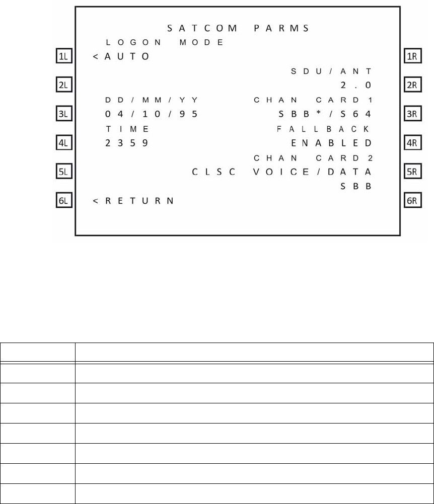
SYSTEM DESCRIPTION, INSTALLATION, AND MAINTENANCE MANUAL
ARINC 781-200 SDU and SCM
23-15-30 2-27
DATE TBD
Figure 2-10 SATCOM PARMS
Table 2-8 describes the information available in the SATCOM PARMS menu.
Table 2-8 SATCOM PARMS Menu
Label Description
LOGON MODE AUTO or MANUAL
DD/MM/YY Current date
TIME Current time
SDU/ANT Estimated loss between the SDU and antenna
CHAN CARD1 Default data mode of operation in ORT.
FAILOVER Disabled—SDI operates in SBB mode.
CHAN CARD2 Service and domain selection ORT parameter—CLSCVOICE/DATA
F. Viewing SATCOM Options
As shown in Figure 2-11, the SATCOM OPTIONS menu provides information about audio
and phone operation.
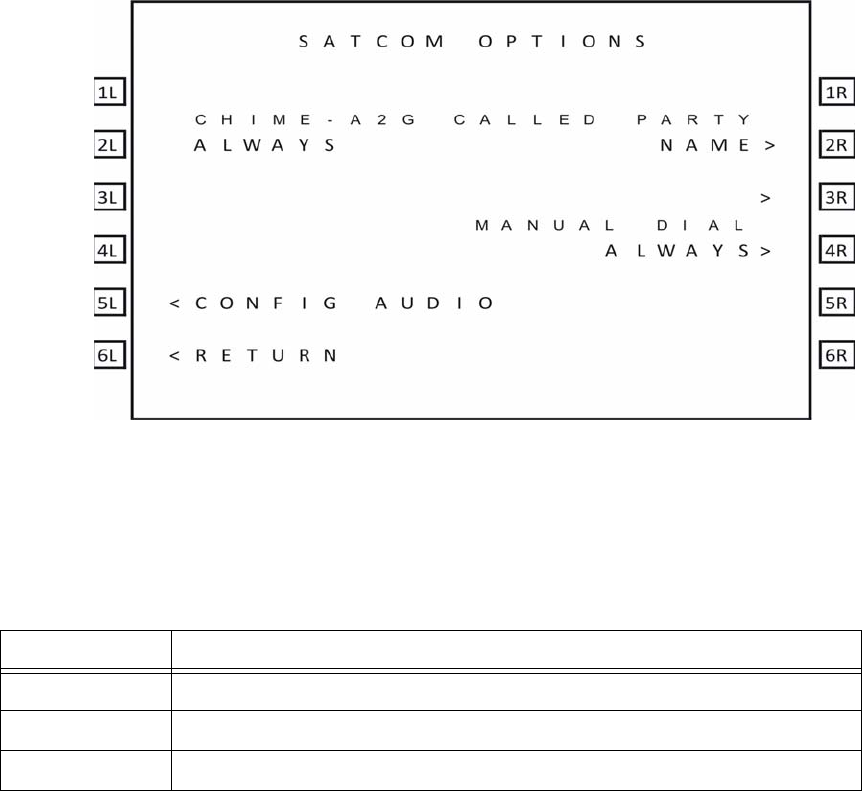
SYSTEM DESCRIPTION, INSTALLATION, AND MAINTENANCE MANUAL
ARINC 781-200 SDU and SCM
23-15-30 2-28
DATE TBD
Figure 2-11 SATCOM OPTIONS
Table 2-9 describes the information available in the SATCOM OPTIONS menu.
Table 2-9 SATCOM OPTIONS Menu
Label Description
CHIME-A2G Value of the CHIME A@G ORT parameter.
CALLED PARTY Display mode selection for call placement.
MANUAL DIAL Current state of the scratchpad number entry control.
G. Configuring Audio Options
As shown in Figure 2-12 and Figure 2-13, the SATCOM CONFIG AUDIO menu provides
information and settings for cockpit phone operation.
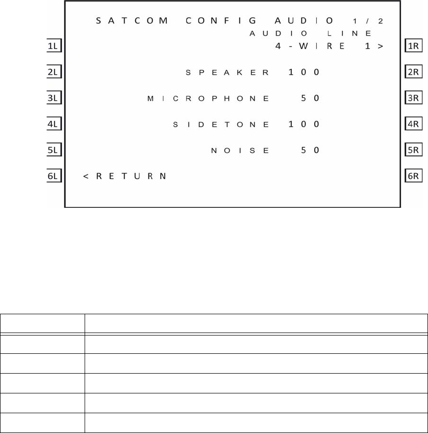
SYSTEM DESCRIPTION, INSTALLATION, AND MAINTENANCE MANUAL
ARINC 781-200 SDU and SCM
23-15-30 2-29
DATE TBD
Figure 2-12 CONFIG AUDIO 1/2
Table 2-10 describes the information available in the SATCOM CONFIG AUDIO 1 menu.
Table 2-10 SATCOM CONFIG AUDIO 1 Menu
Label Description
AUDIO LINE Switch between 4-wire 1 and 4-wire 2.
SPEAKER Headset speaker level—0 to 100.
MICROPHONE Microphone level—0 to 100.
SIDETONE Sidetone level—0 to 100.
NOISE Headset speaker noise level—0 to 100.
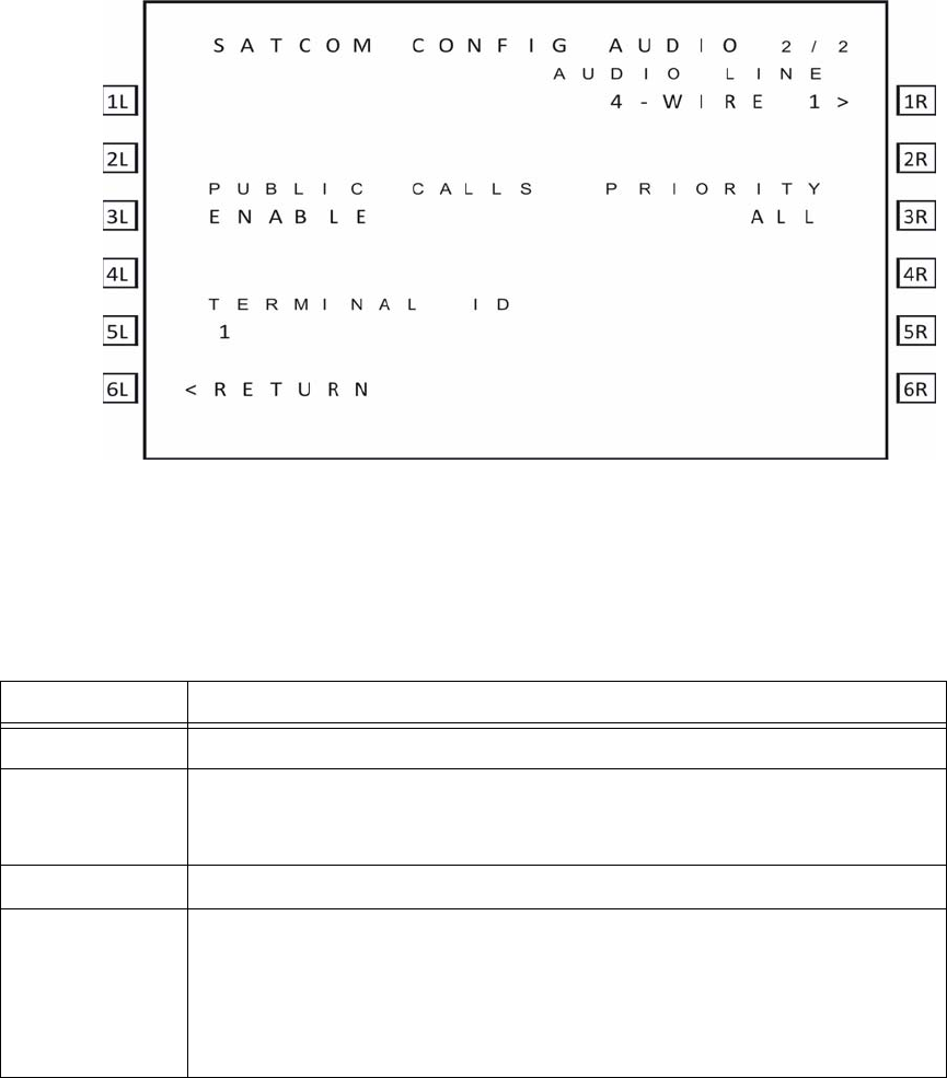
SYSTEM DESCRIPTION, INSTALLATION, AND MAINTENANCE MANUAL
ARINC 781-200 SDU and SCM
23-15-30 2-30
DATE TBD
Figure 2-13 CONFIG AUDIO 2/2
Table 2-11 describes the information available in the SATCOM CONFIG AUDIO 2menu.
Table 2-11 SATCOM CONFIG AUDIO 2 Menu
Label Description
AUDIO LINE Switch between 4-wire 1 and 4-wire 2.
PUBLIC CALLS Displays the value of the Ground Initiated Public Call Routing ORT parameter.
This parameter enables the placing and acceptance of public calls via the
analog audio lines.
TERMINAL ID The terminal ID for the selected audio line interface.
PRIORITY The priority of calls allowed via the selected audio interface. The possible values
are:
• COCKPIT
•PUBLIC
•ALL
SYSTEM DESCRIPTION, INSTALLATION, AND MAINTENANCE MANUAL
ARINC 781-200 SDU and SCM
23-15-30 3-1
DATE TBD
INSTALLATION
This section describes the procedures required to install the A781-200 system (SDU and SCM) on
an aircraft, including the following sections:
• Advisories
• Pre-Installation Inspection
• Installation Procedure
• Connection Details
• Owners Requirements Table (ORT)
• Passive Intermodulation (PIM) Test
• Installation and Engineering Drawings
1. Advisories
Before performing any installation procedures, read the safety advisories listed in the
Introduction on page INTRO–4 of this manual.
2. Pre-Installation Inspection
Before installing any A781-200 system, conduct a pre-installation inspection of all parts to make
sure that no damage occurred during shipping.
A. Unpacking and Inspecting Equipment
• Unpack the A781-200 equipment from the shipping containers.
• Verify that the part number displayed on the shipping box and equipment component
matches the model and part number ordered. If components are missing from the
shipment, contact the supplier immediately and report the problem.
• Visually inspect the A781-200 equipment for any shipping damage. If any shipping
damage has occurred, contact the shipping carrier immediately and report the
problem.
• Check the A781-200 equipment connectors for corrosion and damage. If damage is
noted, do not apply power to the equipment. Contact the supplier immediately to
report the problem.
B. Cabling Notes
Before proceeding with the installation of the A781-200 system, read all cabling notes
provided on the Interconnection and Contact Assignment drawings on page 3–19.

SYSTEM DESCRIPTION, INSTALLATION, AND MAINTENANCE MANUAL
ARINC 781-200 SDU and SCM
23-15-30 3-2
DATE TBD
3. Installation Procedure
Only authorized technical personnel, trained in general aviation workmanship, that have a basic
understanding of SATCOM systems should proceed with the following procedure.
Before performing any installation procedures, read the safety advisories listed in "Advisories"
on page 3-1 of this manual.
CAUTION: THE ARINC 781-200 SYSTEM REQUIRES CONDITIONED AIR PER
ARINC781. SEE NOTE 4 0F FIGURE 3-3 ON PAGE 3–11.
1. Install the SDU in a 6 MCU tray as per ARINC 600. The minimum clearance between
the SDU and any other equipment installed above it shall be no less than 0.5 inches.
2. Install the SCM in any orientation. Refer to Table 1-2 on page 1-5 for the SCM
mounting specification.
• There are no clearance requirements for the SCM.
3. Connect the SCM to the SDU. The SDU supports one RS-422 interface for
interconnect to the SCM.
4. Connect the SDU to the antenna subsystem. The SDU supports ARINC 429
communication to and from the antenna subsystem.
5. Connect the SDU to the MCDU(s). The SDU supports three ARINC 429 receive
interfaces and one ARINC 429 transmit interface for interconnect to the flight deck
MCDU(s).
4. Connection Details
A. SDU
The SDU uses two external interface connectors:
• Rear Connector—a low insertion force, size 2 shell receptacle accommodating
coaxial and signal interconnections in the top plug insert, Quadrax and signal
connections in the middle plug insert, and coaxial and power interconnections in the
bottom plug insert. Pin assignments are compliant with ARINC Characteristic 781
with top plug and middle plug deviations as shown in Table 3-1.
• Front Connector—an RJ45 and 9S DSUB connector providing 10BT Ethernet
interfaces and an RS-232 maintenance interface. Pin assignments are shown in
Table 3-2. The front connector is behind a maintenance cover. This connector
provides access to maintenance and troubleshooting information when the SDU is
not in normal operation.
Table 3-1 SDU Rear Connector Pin Deviations
Pin Number A781 Deviation
Top Plug Insert Pin Deviations
TP01A ATE pin 1 Router Processor Maintenance TXD
TP01B ATE pin 2 Router Processor Maintenance RXD

SYSTEM DESCRIPTION, INSTALLATION, AND MAINTENANCE MANUAL
ARINC 781-200 SDU and SCM
23-15-30 3-3
DATE TBD
TP01C ATE pin 3 Router Processor & Data I/O Processor Maintenance
GND
TP01D ATE pin 4 Data I/O Processor Maintenance TXD
TP01E ATE pin 5 Data I/O Processor Maintenance RXD
TP01F ATE pin 6 CC1 Processors #1 & #2 Maintenance GND
TP01G ATE pin 7 CC1 Processor #1 Maintenance TXD
TP01H ATE pin 8 CC1 Processor #1 Maintenance RXD
TP01J ATE pin 9 CC1 Processor #2 Maintenance TXD
TP01K ATE pin 10 CC1 Processor #2 Maintenance RXD
TP02D ATE pin 14 Voice Processor Maintenance TXD
TP02E ATE pin 15 Voice Processor Maintenance RXD
TP02F ATE pin 16 CC2 Processors #1 & #2 Maintenance GND
TP02G ATE pin 17 CC2 Processor #1 Maintenance TXD
TP02H ATE pin 18 CC2 Processor #1 Maintenance RXD
TP02J ATE pin 19 CC2 Processor #2 Maintenance TXD
TP02K ATE pin 20 CC2 Processor #2 Maintenance RXD
TP03C Empty
Cavity SPARE
TP04C Empty
Cavity SPARE
TP05A Empty
Cavity SPARE
TP05B Empty
Cavity SPARE
TP05C Empty
Cavity SPARE
TP06C Empty
Cavity SPARE
TP07C Empty
Cavity SPARE
Middle Plug Insert Pin Deviations
Table 3-1 SDU Rear Connector Pin Deviations
Pin Number A781 Deviation

SYSTEM DESCRIPTION, INSTALLATION, AND MAINTENANCE MANUAL
ARINC 781-200 SDU and SCM
23-15-30 3-4
DATE TBD
Figure 3-1shows the top plug pin deviations outlined in gray.
MP08E Data
Loader
Link A
Use by 615A Data Loader (Ethernet)
Note 1: Wiring harness to SCM provides 2 physical connections to each pin
Table 3-1 SDU Rear Connector Pin Deviations
Pin Number A781 Deviation
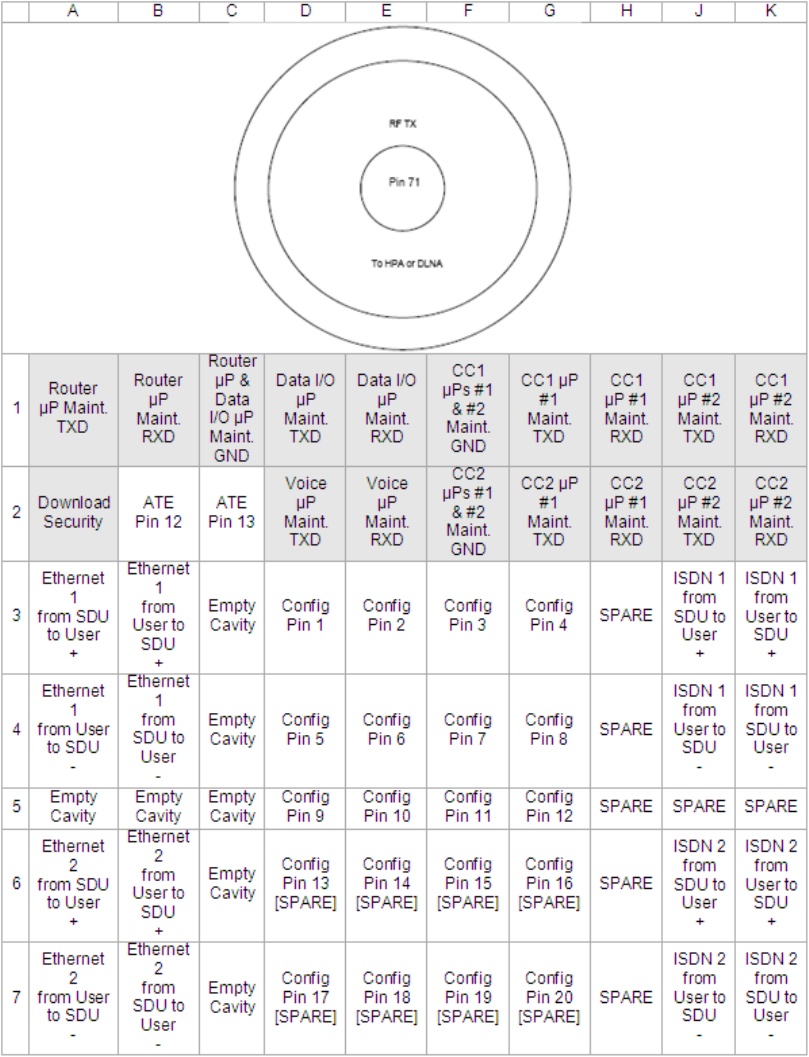
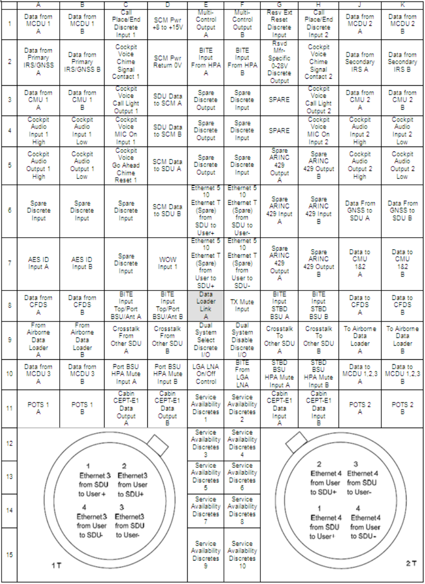
SYSTEM DESCRIPTION, INSTALLATION, AND MAINTENANCE MANUAL
ARINC 781-200 SDU and SCM
23-15-30 3-6
DATE TBD
Figure 3-2 Mid Plug Pin Deviations

Table 3-2 SDU Front Connector DSUB and RJ45 Pin Assignment
9S DSUB Pin
Number Description RJ45 Pin Number Description
1NC 1RX+
2TX 2RX-
3RX 3TX+
4NC 4NC
5GND 5NC
6NC 6TX-
7NC 7NC
8NC 8NC
9NC
SYSTEM DESCRIPTION, INSTALLATION, AND MAINTENANCE MANUAL
ARINC 781-200 SDU and SCM
23-15-30 3-7
DATE TBD
B. SCM
The SCM uses a 15 pin D-type male connector and locking screws. Pin assignments are
compliant with ARINC Characteristic 781 and shown in Table 3-3.
Table 3-3 SCM D-Type Connector Pin Assignment
Pin Number Description
1Data to SDU A (RS422)
2Data to SDU B (RS422)
3Data from SDU A (RS422)
4Data from SDU B (RS422)
5Reserved - RS232 Gnd (used for shop loading)
6Spare
7Chassis Ground
8Power Input +8 V to +15 V
9Reserved - Enable RS232 (used for shop loading)
10 Reserved - 0 V strap output (used for shop loading)
11 Spare
12 Reserved - RS232 Tx (used for shop loading)
13 Reserved - RS232 Rx (used for shop loading)
14 Spare

SYSTEM DESCRIPTION, INSTALLATION, AND MAINTENANCE MANUAL
ARINC 781-200 SDU and SCM
23-15-30 3-8
DATE TBD
5. Owners Requirements Table (ORT)
A. ORT Overview
The A781-200 system includes a secure and user ORT. Secure ORT files must be
certified for the aircraft type on which the equipment is installed. Items in user ORT files
can be modified by individual customers and may be customized to an individual aircraft.
You can change secure ORT parameters only by uploading an ORT file. To obtain an
ORT file, contact RCI Product Support.
The ORT file is loaded on to the SCM using an ARINC 615A data loader. You can only
load ORT data when the aircraft is on the ground and the data load discrete is asserted.
When the SDU boots, it compares the ORT file in its memory to that in the SCM. If the
ORT files do not match, the SDU loads the file from the SCM into its memory.
Some user ORT parameters can be modified in the SDU ORT. You can reset the SDU
ORT to the default values stored in the SCM in the maintenance menus.
For more information see the following Guides:
• MN-0000461, A781-200 User Ort User Guide
• MN-0000462, A781-200 Secure ORT User Guide
• MN-0000463, A781-200 ORT Application Install Manual
6. Passive Intermodulation (PIM) Test
This section describes the passive intermodulation (PIM) test. You must execute the PIM test
after installation if the A781-200 SDU operates in SwiftBroadband mode.
A. Overview
To meet Inmarsat requirements for SBB operation, the A781-200 SDU can test for passive
intermodulation effects. The PIM test verifies that the transmit signal from the A781-200
SDU does not degrade or interfere with the receive signals as a result of PIM.
A781-200 SDU can only perform the PIM test when the aircraft is on the ground.
When the A781-200 SDU logs on to the SBB network, the network assigns the terminal
two channels for PIM testing. These channels are not used by other terminals so that the
A781-200 SDU can transmit the test frequencies without interfering with other satellite
communication equipment or the Inmarsat satellite.
B. PIM Requirements
In order to successfully perform the PIM test, the aircraft and the satellite communication
system must meet the following requirements:
15 Power Return 0 V
Table 3-3 SCM D-Type Connector Pin Assignment (Continued)
Pin Number Description
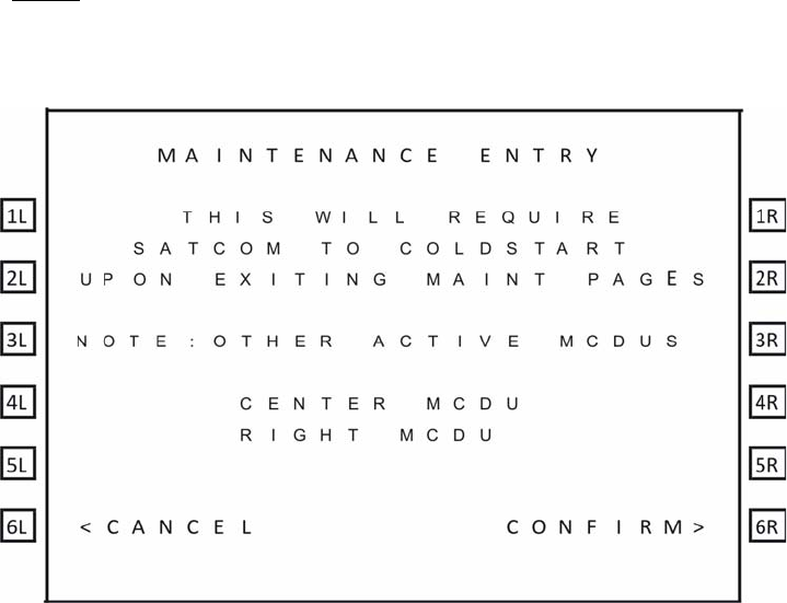
SYSTEM DESCRIPTION, INSTALLATION, AND MAINTENANCE MANUAL
ARINC 781-200 SDU and SCM
23-15-30 3-9
DATE TBD
• The A781-200 SDU must have successfully logged on to a satellite that is visible at
the test location within the last 168 hours (7 days).
• The aircraft has to be outside the hangar and far away from the hangars and towers
in order to obtain good results.
• The aircraft must be facing due north in the northern hemisphere, and due south in
the southern hemisphere.
C. PIM Test
To run the PIM test you must be in maintenance mode. You can only access the MCDU
maintenance menus when the plane is on the ground and classic services are logged off.
To start the PIM test:
1. In the MCDU CONFIG 1/4 menu, type the protection level code in the scratchpad,
and press the button next PROT LEVEL CODE.
NOTE: Contact RCI product support for the PROT level code.
The SATCOM Maintenance Entry page appears.
2. To enter maintenance mode, press the button next to CONFIRM.
The MAINTENANCE MENU appears.
3. To start the PIM test, press the button next to INTERMOD TEST.
The PIM test starts. The test takes about five minutes.
D. PIM Test Results
(1) PIM Test Overall Status
At the end of the PIM test, the A781-200 SDU displays the test results on the MCDU
screen.
SYSTEM DESCRIPTION, INSTALLATION, AND MAINTENANCE MANUAL
ARINC 781-200 SDU and SCM
23-15-30 3-10
DATE TBD
The MCDU displays the overall PIM status and results for each direction. If the overall
status is PASS, the SDU can continue to use SBB services.
If the overall status is FAIL:
• Check the cable connections of the antenna and the SDU.
• Check the direction in which the test failed and verify that the antenna is not
blocked in that direction—see "Directional PIM Test Results" on page 3-10.
(2) Directional PIM Test Results
The SDU performs the PIM test with the antenna pointing in different directions and
displays the results of the test in each direction. If the overall status of the PIM test
is FAIL, you can check the specific directions in which the test failed.
For each direction, the PIM test results provide:
• Overall Status—pass or fail.
• The direction coordinates.
• The signal degradation—the maximum value to pass the test is 3 dB.
• Possible interference—interference caused by environmental factors, not the
SDU transmit frequencies. Interference indicates that the SDU received a signal
in the receive band even when it wasn’t transmitting, therefore an external signal
may be interfering with communication in that direction.
• Signal and noise levels before and after the test—the SDU uses this information
to check for possible interference.
7. Installation and Engineering Drawings
This section contains the Outline and Installation diagrams, and Interconnection and Contact
Assignment drawings for the SDU and SCM.
All foldout pages are odd-numbered and not-backed for print production purposes.
A. Outline and Installation Drawings
The Outline and Installation drawings on pages 3–11 to 3–17 show the physical
characteristics of the SDU and SCM, and provide installation data for the system.
B. System Interconnect Drawings
System Interconnect drawings on pages 3–19 to 3–23 show the interconnection details
for the SDU and SCM.
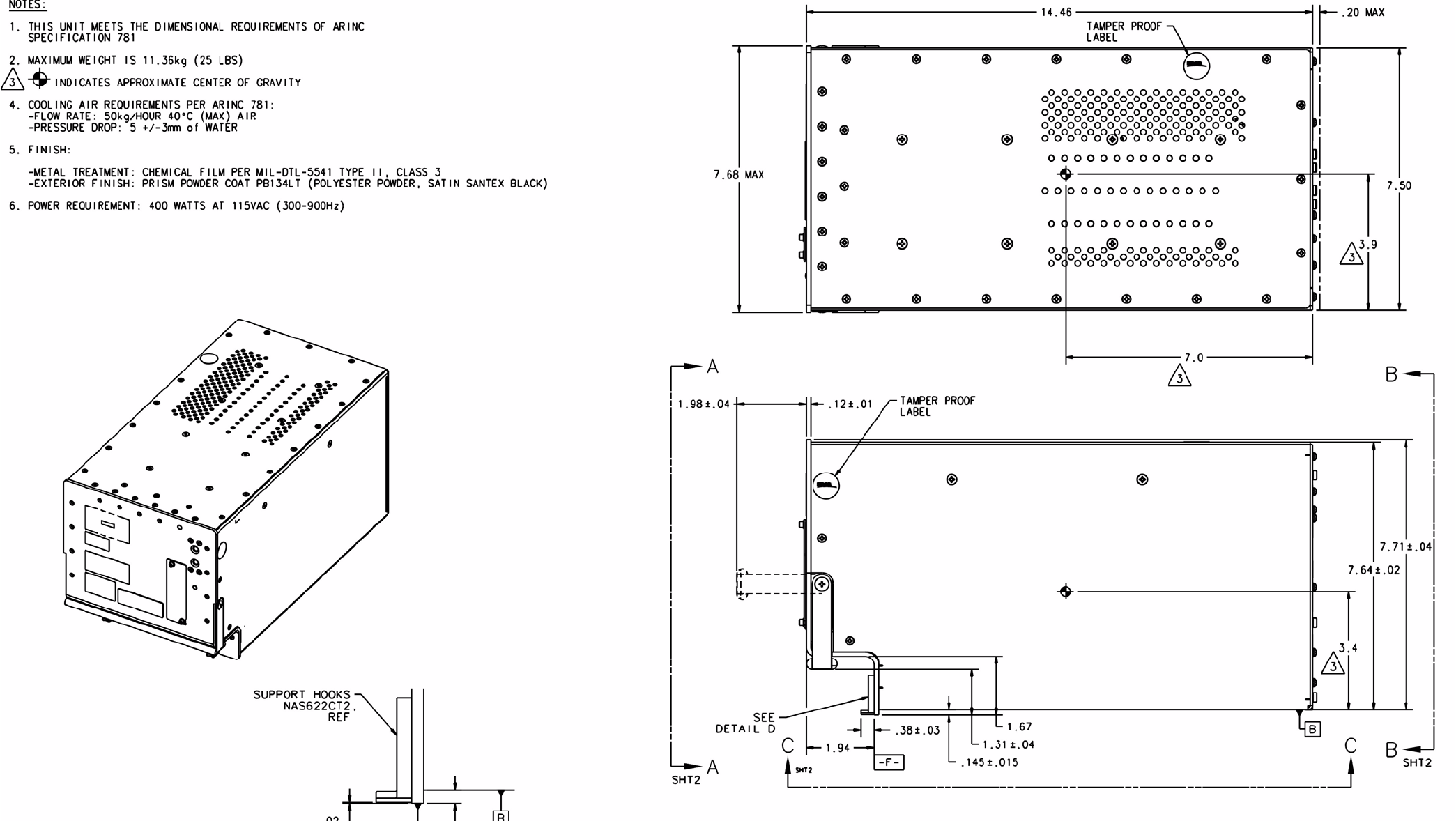
SYSTEM DESCRIPTION, INSTALLATION, AND MAINTENANCE MANUAL
ARINC 781-200 SDU and SCM
23-15-30 3-11
DATE TBD
Figure 3-3 ARINC 781-200 SDU Outline and Installation Drawing, 1530-E-1100 Rev B00 (Sheet 1 of 2)
SYSTEM DESCRIPTION, INSTALLATION, AND MAINTENANCE MANUAL
ARINC 781-200 SDU and SCM
23-15-30 3-12
DATE TBD
Blank Page
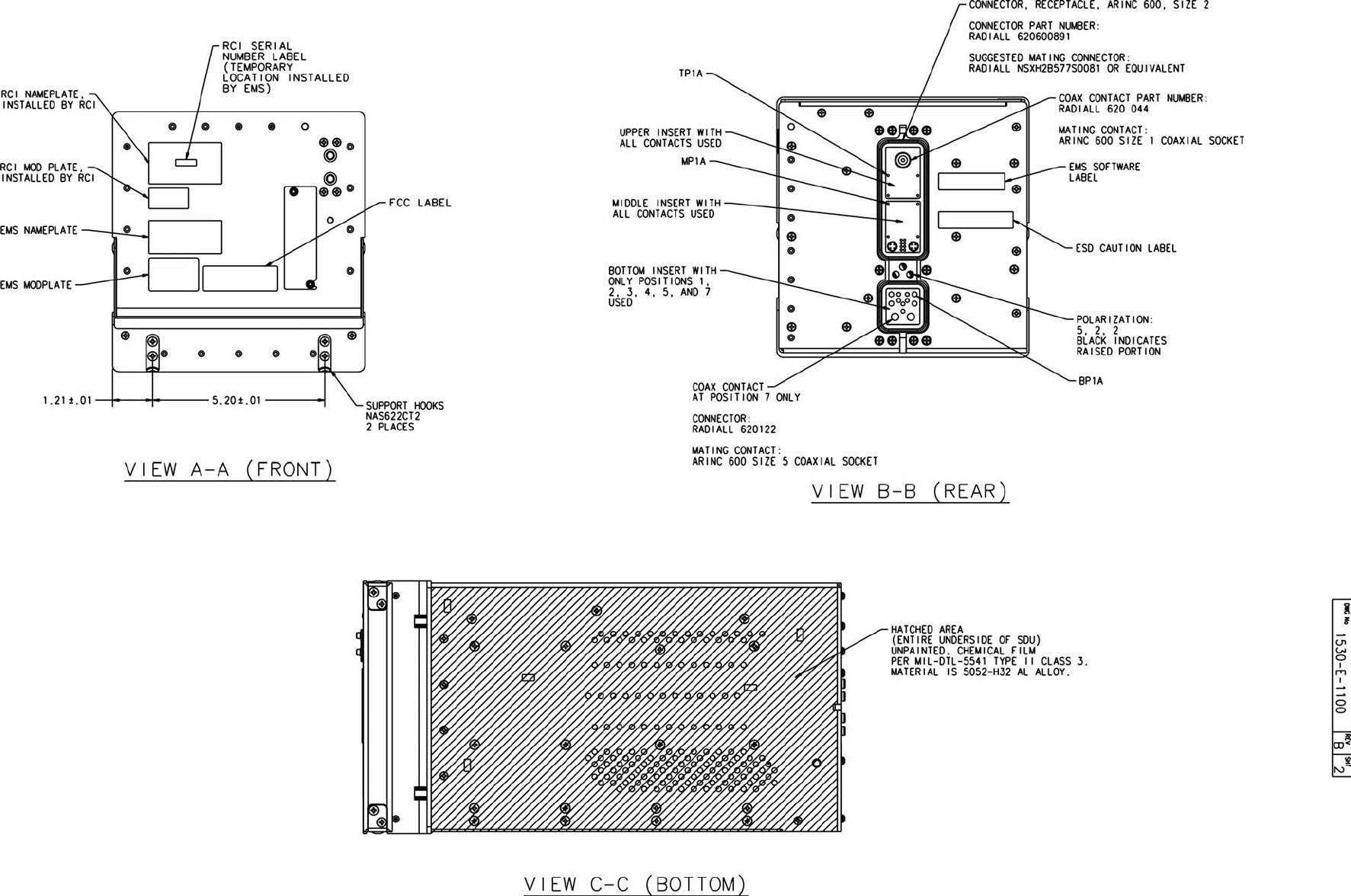
SYSTEM DESCRIPTION, INSTALLATION, AND MAINTENANCE MANUAL
ARINC 781-200 SDU and SCM
23-15-30 3-13
DATE TBD
Figure 3-4 ARINC 781-200 SDU Outline and Installation Drawing, 1530-E-1100 Rev B00 (Sheet 2 of 2)
SYSTEM DESCRIPTION, INSTALLATION, AND MAINTENANCE MANUAL
ARINC 781-200 SDU and SCM
23-15-30 3-14
DATE TBD
Blank Page
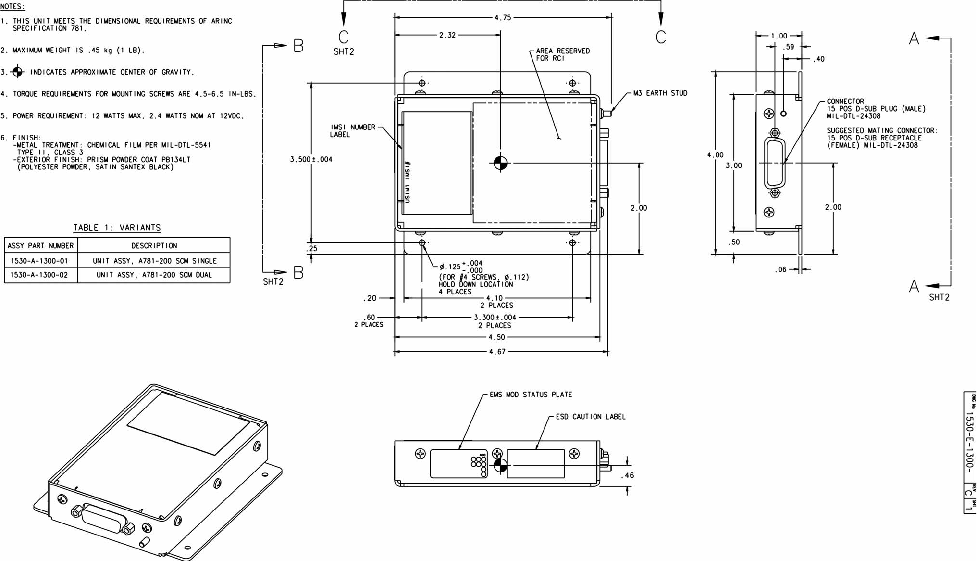
SYSTEM DESCRIPTION, INSTALLATION, AND MAINTENANCE MANUAL
ARINC 781-200 SDU and SCM
23-15-30 3-15
DATE TBD
Figure 3-5 ARINC 781-200 SCM Outline and Installation Drawing, 1530-E-1300 Rev C00 (Sheet 1 of 2)
SYSTEM DESCRIPTION, INSTALLATION, AND MAINTENANCE MANUAL
ARINC 781-200 SDU and SCM
23-15-30 3-16
DATE TBD
Blank Page
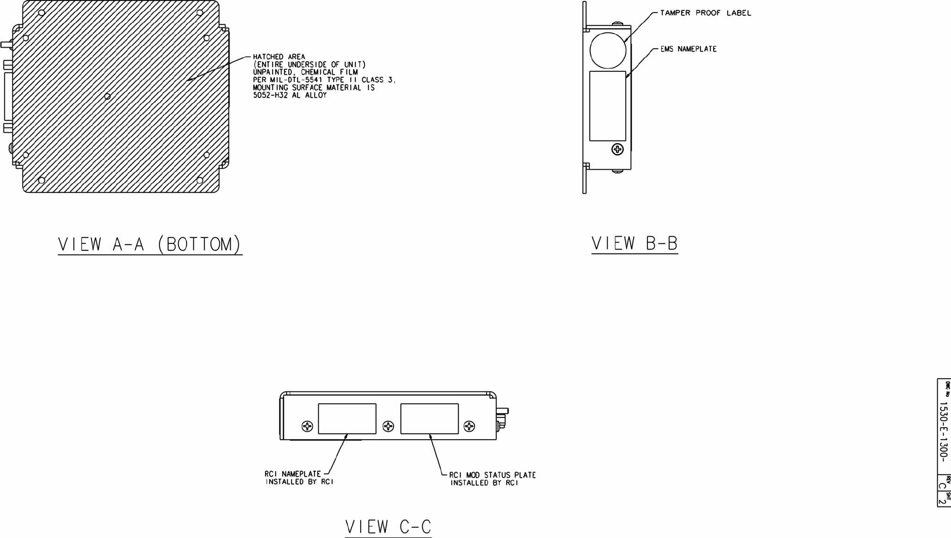
SYSTEM DESCRIPTION, INSTALLATION, AND MAINTENANCE MANUAL
ARINC 781-200 SDU and SCM
23-15-30 3-17
DATE TBD
Figure 3-6 ARINC 781-200 SCM Outline and Installation Drawing, 1530-E-1300 Rev C00 (Sheet 2 of 2)
SYSTEM DESCRIPTION, INSTALLATION, AND MAINTENANCE MANUAL
ARINC 781-200 SDU and SCM
23-15-30 3-18
DATE TBD
Blank Page
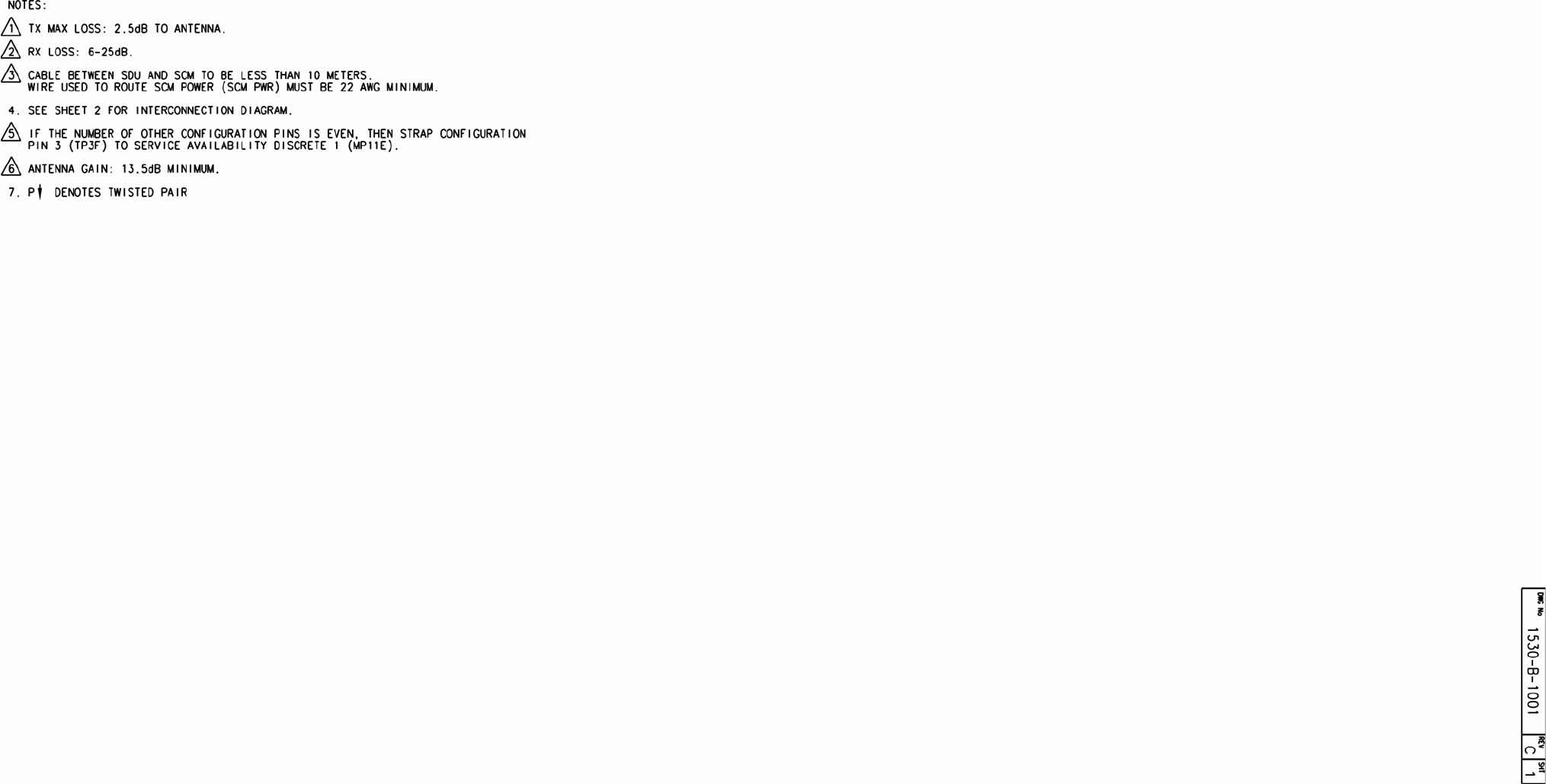
SYSTEM DESCRIPTION, INSTALLATION, AND MAINTENANCE MANUAL
ARINC 781-200 SDU and SCM
23-15-30 3-19
DATE TBD
Figure 3-7 ARINC 781-200 System Interconnect Drawing, 1530-B-1001 Rev C00 (Sheet 1 of 3)
SYSTEM DESCRIPTION, INSTALLATION, AND MAINTENANCE MANUAL
ARINC 781-200 SDU and SCM
23-15-30 3-20
DATE TBD
Blank Page
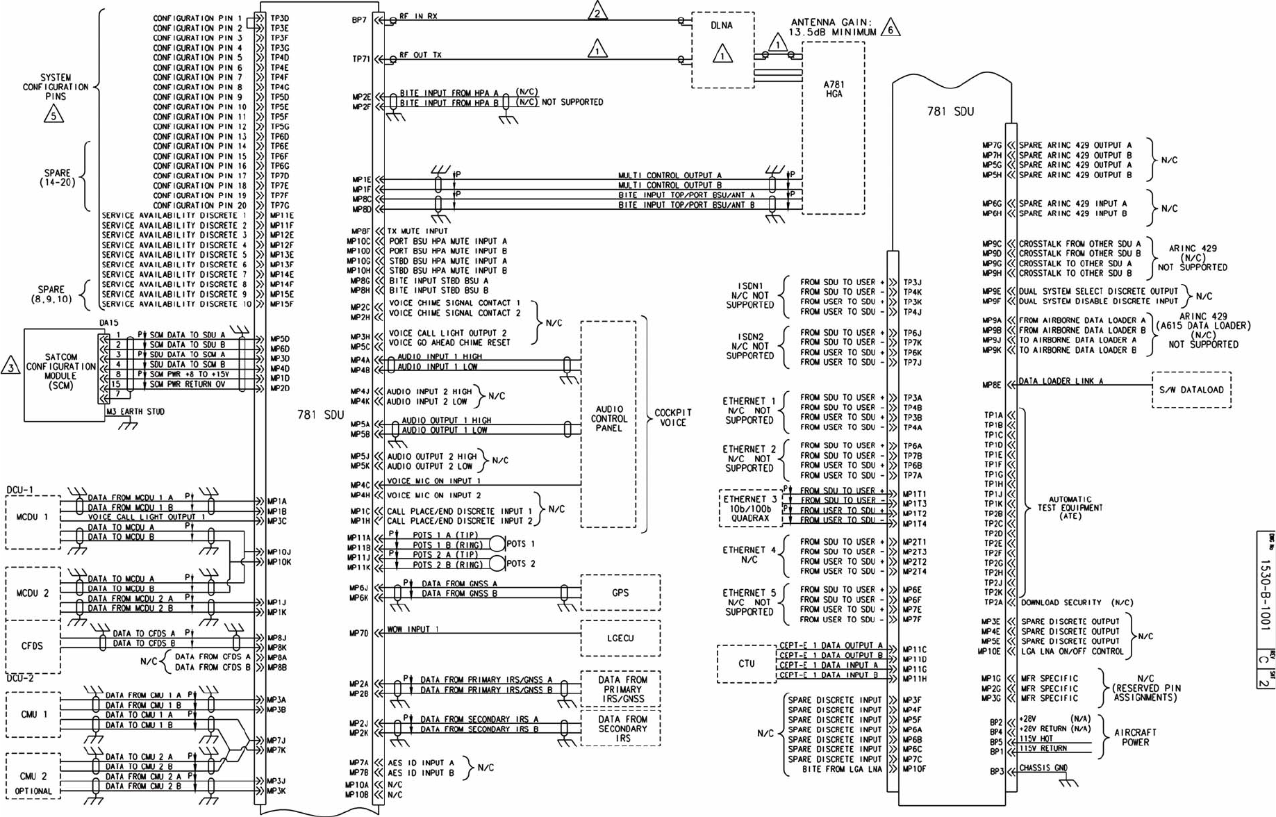
SYSTEM DESCRIPTION, INSTALLATION, AND MAINTENANCE MANUAL
ARINC 781-200 SDU and SCM
23-15-30 3-21
DATE TBD
Figure 3-8 ARINC 781-200 System Interconnect Drawing, 1530-B-1001 Rev C00 (Sheet 2 of 3)
SYSTEM DESCRIPTION, INSTALLATION, AND MAINTENANCE MANUAL
ARINC 781-200 SDU and SCM
23-15-30 3-22
DATE TBD
Blank Page
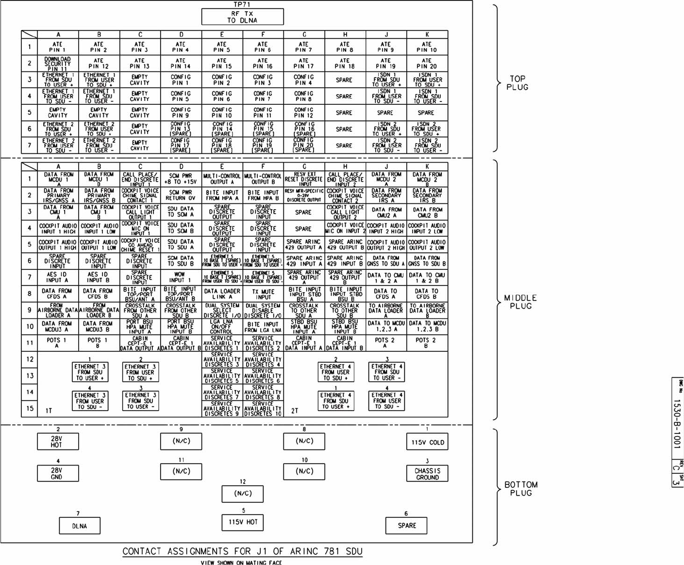
SYSTEM DESCRIPTION, INSTALLATION, AND MAINTENANCE MANUAL
ARINC 781-200 SDU and SCM
23-15-30 3-23
DATE TBD
Figure 3-9 ARINC 781-200 System Interconnect Drawing, 1530-B-1001 Rev C00 (Sheet 3 of 3)
SYSTEM DESCRIPTION, INSTALLATION, AND MAINTENANCE MANUAL
ARINC 781-200 SDU and SCM
23-15-30 3-24
DATE TBD
Blank Page

SYSTEM DESCRIPTION, INSTALLATION, AND MAINTENANCE MANUAL
ARINC 781-200 SDU and SCM
23-15-30 4-1
DATE TBD
TEST AND FAULT ISOLATION
This section provides test procedures to determine the operational readiness of SDU units.
There are no operational test procedures defined for the SCM. SCM health is determined by
accessing the SDU BITE information.
If the A781-200 equipment passes all tests in this section but does not function according to the
installation requirements, the fault may be with equipment or wiring outside the A781-200 system.
This section includes:
• Operational and Diagnostic Testing
• Troubleshooting and Fault Isolation
• Adjustment/Alignment Procedures
• Modification History
NOTE: Depending on the version of software installed, the MPU menus described may differ from
those shown as examples in this manual.
1. Operational and Diagnostic Testing
This section includes the following sections:
• General
• Test and Fault Isolation Equipment Requirements
• SDU Maintenance Port Utility (MPU)
• Operational and Diagnostic Test Procedures
A. General
The A781-200 system requires testing for one of the following reasons:
• To verify the operational readiness of the system after installation on an aircraft
• To verify that a fault exists and produce system reports for troubleshooting purposes
• To verify the operational readiness of repaired LRUs after re-installation on an aircraft
This section includes test and fault isolation procedures for the A781-200 system. All test
and load procedures require the A781-200 SDU MPU, which is accessed by connecting
to the maintenance port of the SDU.
B. Test and Fault Isolation Equipment Requirements
Table 4-1 lists the equipment required to access the SDU Maintenance Port Utility (MPU)
and perform operational and diagnostic testing on the SDU.
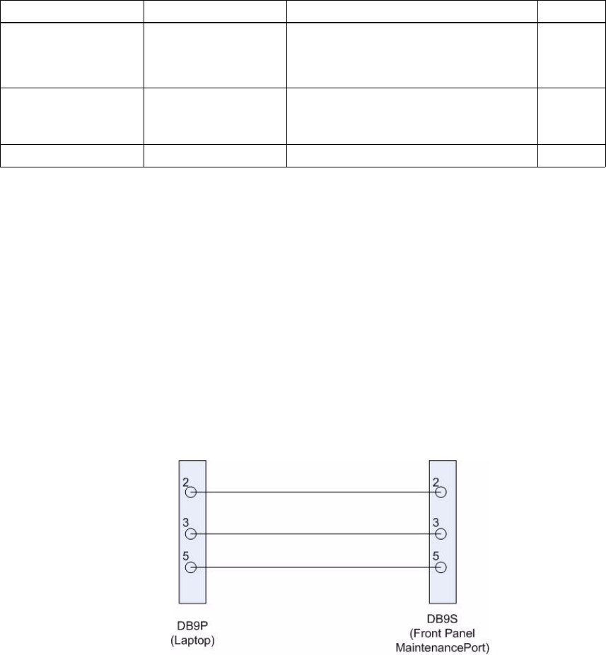
Table 4-1 List of Required Test Equipment
Item Equipment Specification Quantity
Computer Standard PC running VT-100 terminal emulator
such as HyperTeminal and equipped
with an RS-232 port.
1
VT-100 terminal
emulation program HyperTerminal©,
ProComm Plus©, or
equivalent
Serial communication program using an
RS-232 port 1
Cable RS-232 cable Maximum length 25 feet 1
SYSTEM DESCRIPTION, INSTALLATION, AND MAINTENANCE MANUAL
ARINC 781-200 SDU and SCM
23-15-30 4-2
DATE TBD
C. SDU Maintenance Port Utility (MPU)
This section describes the SDU MPU and provides the connection and cabling details
required to access and use the program.
(1) Connecting to the MPU
The MPU provides a system interface for fault isolation and diagnostic procedures.
To use the SDU MPU, connect an RS-232, VT-100 terminal (computer operating a
terminal emulation program) to the RS-232 maintenance port interface of the SDU.
The maintenance port on the front panel of the SDU provides a direct connection to
the MPU using a DB9 connector.
Figure 4-1 provides cabling details for the SDU maintenance port.
Figure 4-1 Maintenance Cable
(a) Interface Requirements
A standard VT-100 compatible terminal running an emulator program (such as
HyperTerminal, ProComm Plus, or similar) provides the user interface to the SDU
MPU. The RS-232 terminal connection settings for SDU maintenance ports are
listed in Table 4-2.

Table 4-2 Maintenance Port Connection Settings
Parameter Setting
Character Format ASCII
Baud Rate 19200 bps
No. of bits 8
Parity None
Stop bits 1
Flow Control None
SYSTEM DESCRIPTION, INSTALLATION, AND MAINTENANCE MANUAL
ARINC 781-200 SDU and SCM
23-15-30 4-3
DATE TBD
(2) Using the SDU MPU
This section describes the basic procedures for using and navigating the SDU MPU.
NOTE: There are various levels of access to the MPU. Each level is protected by a
different password. This section describes the MPU functions available using
the Level 1 password.
(a) Entering Passwords
You can enter the password any time after the SDU boots.
• To access Level 1 functions, type menu.
NOTE: The password does not appear on the screen when you type it.
(b) Navigating the SDU MPU
• To scroll through the available menus, press CTRL+N.
• To go to the previous menu, press CTRL+O.
• To refresh the menu screen or exit from a Reports Menu, press ESC.
(c) Selecting Menu Items
• To enable test or data entry functions, press the letter associated with the
menu items.
(d) Selecting Reports
The reports available through the MPU enable users to view information about
the configuration and status of the SDU. This information is used to troubleshoot
the communication system on the aircraft.
To access reports:
1. In the MPU, press EQUAL SIGN (=).
A list of reports appears. Active reports show as toggled on. Inactive reports
show as toggled off.
2. To activate a report, type the report number, and then press ENTER.
NOTE: Multiple reports can be activated at the same time; type and enter
each report number separately.
3. To turn off individual, active reports, type the report number you want to
toggle off, and then press ENTER.

SYSTEM DESCRIPTION, INSTALLATION, AND MAINTENANCE MANUAL
ARINC 781-200 SDU and SCM
23-15-30 4-4
DATE TBD
4. To turn off all active reports, press EQUAL SIGN (=), and then press X.
(3) Menu Item Descriptions
This section provides a brief description of the Level 1, MPU menu items used for
test and fault isolation procedures.
In active SDUs, menu screens display the firmware version.
NOTE: Depending on the version of software installed and the system configuration,
the menu and reports available to users may differ slightly from the reports
described in this document.
(a) Menu 1
Table 4-3 describes the items available in Menu 1.
(b) Menu 2
Table 4-4 describes the items available in Menu 2.
Table 4-3 Menu 1 Item Descriptions
Menu Item Description
Y: explain error status Reports error status when failure LED is illuminated. Displays OK if no error
exists.
F: print equipment
statsPrints a list of the current equipment statistics, including temperature,
number of power-ups, hours of operation, time since power-up, and
processor usage.
Table 4-4 Menu 2 Item Descriptions
Menu Item Description
L: re-enter logon
password Permits a user to enter a new access level password without having to
reboot the SDU.
Z: reset A781 SDU Enables a complete, soft reset of the SDU; once reset, the menu access
password must be re-entered.
H: query SDU-FMPA
cable loss Initiates the cable loss determined in auto-calibration.
V: get firmware versions Displays the kernel and application software versions for the Control
Processor, Data I/O Processor, Channel Cards
C: query loss of cooling
mode Indicates if loss of cooling mode is active or inactive.
(c) Menu 3
Table 4-5 describes the items available in Menu 3.
Table 4-5 Menu 3 Item Descriptions
Menu Item Description
F: list call log Lists Classic call logs for the following events:
• Successful Aero Log-on
• Air-to-ground calls accepted by the SDU
• Ground-to-air calls accepted by the SDU
Lists SBB call logs for the following events:
• Attachment or modification of attachment, including change of beam ID
• Creation or deletion of primary or secondary contexts
O: list DIO ORT Lists of ORT items destined for the Data Processor in human readable
form.
Y: verify CP ORT Verifies if file name of the internal copies of the Secure and User ORT
are valid or corrupted.
G: clear call log Clears the call log after a confirmation.
H: list CP ORT Lists ORT settings and how they were configured (either by default or
through the maintenance port, or via SCM ORT files). “Set by
maintenance port” indicates that the ORT parameter is set by the
maintenance port.
SYSTEM DESCRIPTION, INSTALLATION, AND MAINTENANCE MANUAL
ARINC 781-200 SDU and SCM
23-15-30 4-5
DATE TBD
D. Operational and Diagnostic Test Procedures
You can perform all test procedures presented in this section to test the total operational
status of the A781-200 system. You can conduct these operational tests for all equipment
returned to service after repair.
The procedures assume that the technical personnel are familiar with the test equipment
used and can operate the equipment to produce the required inputs and obtain the
required results (indications). Refer to the detailed operating procedures and descriptions
of the SDU MPU included in this section.
CAUTION: ONLY AUTHORIZED TECHNICAL PERSONNEL WHO ARE TRAINED IN
GENERAL AVIATION WORKMANSHIP AND HAVE A BASIC
UNDERSTANDING OF SATCOM SYSTEMS SHOULD PERFORM THE
OPERATIONAL AND DIAGNOSTIC TEST PROCEDURES IN THIS
MANUAL.
CAUTION: CHANGES TO DEFAULT VALUES FOR SOME MENU FUNCTIONS MAY
SERIOUSLY DEGRADE SYSTEM OPERATION.
NOTE: This manual describes the basic MPU functions, menus, and reports required
for the testing and fault isolation procedures presented in this section. Please
consult RCI Product Support before entering any unfamiliar menu selections not
described in this manual.
NOTE: Using a terminal emulation program, open a log file and save all test results for
future reference and test records.

SYSTEM DESCRIPTION, INSTALLATION, AND MAINTENANCE MANUAL
ARINC 781-200 SDU and SCM
23-15-30 4-6
DATE TBD
Refer to the Outline and Installation diagrams (Figure 3-1 to Figure 3-6) and the
Interconnection and Contact Assignment drawings (Figure 3-7 to Figure 3-9) for additional
information.
(1) Test Setup Procedure
The test setup procedure is presented in Table 4-6.
Table 4-6 Test Setup Procedure
Step Action
1.0 Make sure that the SDU is powered down and disconnected from the power source.
2.0 Remove the maintenance-port connector cover.
3.0 Connect a maintenance cable to the SDU front-panel maintenance port connector.
4.0 Connect the other end of the cable to the serial port of the computer.
5.0 Open a log file to capture all test data. A log file is a text capture of the ASCII traffic
between the computer attached to the maintenance port and the SDU.
(2) Post Test
When testing is completed, follow the steps in Table 4-7.
Table 4-7 Post Test Procedure
Step Action
1.0 Save the log file of the test results (or data) for future reference.
2.0 Remove power from the SDU that was tested and from all other test equipment.
3.0 Disconnect test equipment from the SDU.
4.0 Replace the maintenance-port connector cover (if it was removed during the test
setup).
If the Unit Under Test (UUT) PASSED the test, the unit is ready for service.
If the UUT FAILED the test, return the UUT along with a hardcopy printout of the recorded
(captured) log file of the test results to the manufacturer for service and repair. Indicate
the date of the test and the serial number of the UUT on the test documentation.
(3) Installation and Operational Verification Tests
To verify that the A781-200 system is ready for operation, use the following
procedures:
• Power-On Test
• BITE
(a) Power-On Test
To complete the power-on test, follow the steps in Table 4-8.

SYSTEM DESCRIPTION, INSTALLATION, AND MAINTENANCE MANUAL
ARINC 781-200 SDU and SCM
23-15-30 4-7
DATE TBD
(b) BITE
If equipment connected to the A781-200 system provides wrong information or
does not provide a signal to the A781-200 SDU, the SDU cannot function
properly. You can check the status of connected equipment with the MCDU BITE
screens. To check the status of connected equipment, follow the procedure
described in "Viewing BITE Information" on page 2-15 and "Troubleshooting and
Fault Isolation" on page 4-7.
The SATCOM BITE menu provides information about the results from BITE for
various parts of the A781-200 system.
• If BITE fails the SDU or SCM, remove the component from service and return
it to RCI—see "Maintenance and Repair" on page 5-1.
• If BITE fails a component other than the A781-200 SDU or SCM, verify the
operation of that component and test the satellite communication system
again.
2. Troubleshooting and Fault Isolation
This section provides troubleshooting procedures for A781-200 systems.
Troubleshooting procedures require data obtained using the MCDU. For specific instructions
on how to access and use the MCDU, refer to "Operating the MCDU" on page 2-2.
NOTE: All of the MCDU menus discussed in this section are accessed from the SATCOM
BITE menu.
A. Subsystem Health
The SATCOM SUBSY HLTH menu provides the BITE status of subsystem components.
To check the subsystem health, on the SATCOM BITE menu, press the button next to
SUBSY HLTH.
Figure 4-2 illustrates the SATCOM SUBSY HLTH menu.
Table 4-8 Power-On Test Procedure
Step Action
1.0 Follow the test setup procedure in Table 4-6 on page 4-6.
2.0 Power-on the SDU.
3.0 Check the status of the front panel LEDs. Verify that the green LED flashes for 60
seconds and then turns off. Verify that the red LED is not illuminated. For more
information about the LED signals, refer to "LEDs" on page 1-9.
4.0 Review the BITE status of all system components using the MCDU. Verify that all
subsystems show OK status. For more information about using the MCDU and
viewing BITE, refer to "Operating the MCDU" on page 2-2 and "BITE" on page 4-7.
5.0 Follow the post test procedure in Table 4-7 on page 4-6.
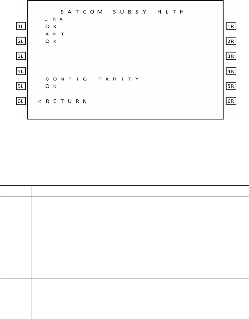
SYSTEM DESCRIPTION, INSTALLATION, AND MAINTENANCE MANUAL
ARINC 781-200 SDU and SCM
23-15-30 4-8
DATE TBD
Figure 4-2 SATCOM Subsystem Health Menu
Table 4-9 describes the information available on the SATCOM SUBSY HLTH menu.
B. SATCOM System Bus
The SATCOM SYSTEM BUS menu provides information about the bus status of
equipment outside the A781-200 system. SATCOM services are not available if the
equipment does not operate or communicate properly.
Table 4-9 SATCOM Subsystem Health Menu
Label Description Action
LNA Reports the status of the LNA as OK, NO DATA (if
golden label 350 from the antenna is missing or
HGA is disconnected), TEST, or FAULT. The LNA
status matches the HDA status.
If the status is NO DATA, check
the bus connections from the
Antenna and check the speed of
bus.
If the status is FAULT, test or
troubleshoot the LNA equipment.
ANT Reports the status of the HGA as OK, FAULT,
TEST, or NO DATA. If the status is FAULT, test or
troubleshoot the HGA equipment.
If the status is NO DATA check the
ARINC 429 bus from the Antenna.
CONFIG
PARITY Reports the status of the rear connector
configuration parity as OK (parity is odd) or FAULT
(parity is not odd). This status can be different from
the setting of Bit 25 in Label 350 to the CMC, which
is also set if the secure ORT is missing or invalid.
If the status is FAULT, check
strapping—a non-supported
configuration may be strapped.
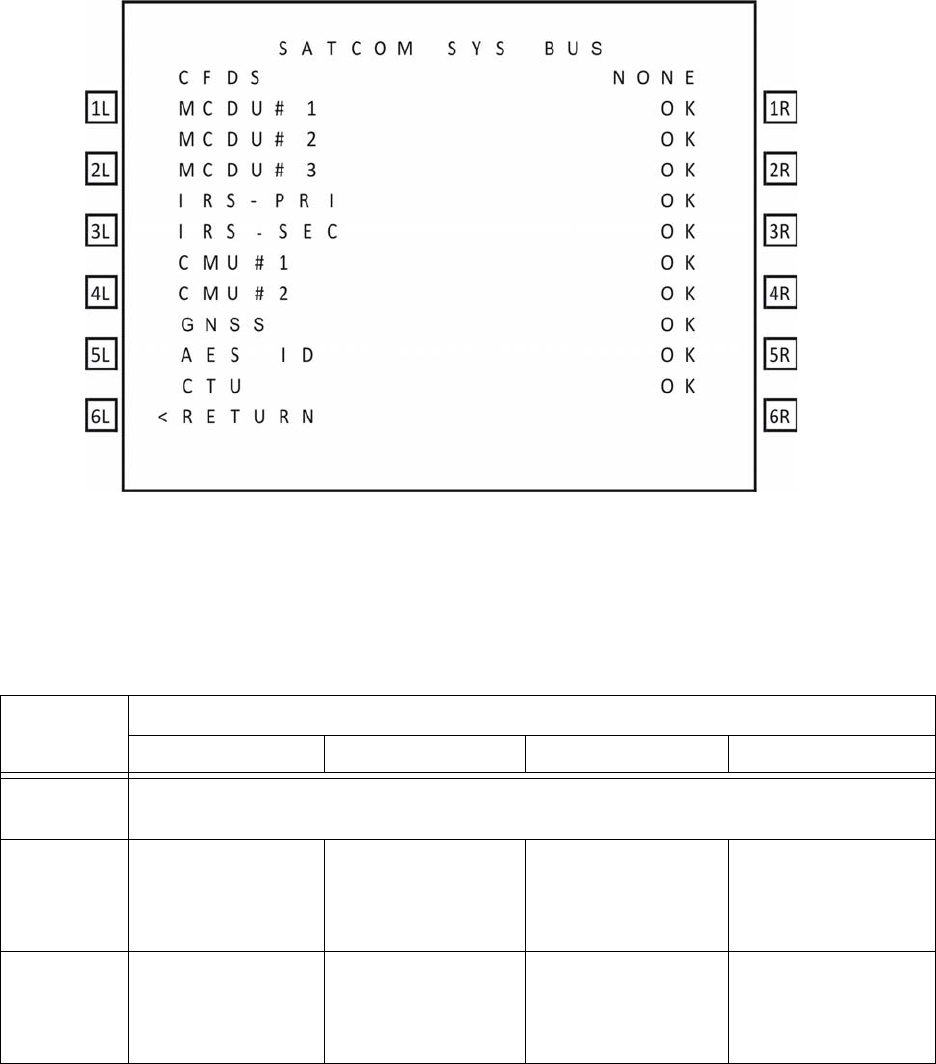
SYSTEM DESCRIPTION, INSTALLATION, AND MAINTENANCE MANUAL
ARINC 781-200 SDU and SCM
23-15-30 4-9
DATE TBD
To check the bus status, on the SATCOM BITE menu, press the button next to SYS BUS.
Figure illustrates the SATCOM System Bus menu.
Figure 4-3 SATCOM System Bus Menu
Table 4-10 describes the information available on the SATCOM SYS BUS menu.
Table 4-10 Bus Status Indicators
Bus Status
INACTIVE NO DATA NONE OK
CFDS The A781-200 does not support or receive input from the CFDS. Therefore the status will
always be NONE.
MCDU No labels of correct
speed on bus. The expected Golden
label (377) is not
present.
The bus is not
installed. The expected Golden
label is present and the
bus is active at the
correct speed.
IRS - PRI No labels of correct
speed on bus. The expected Golden
label (310) is not
present.
N/A The expected Golden
label is present and the
bus is active at the
correct speed.

SYSTEM DESCRIPTION, INSTALLATION, AND MAINTENANCE MANUAL
ARINC 781-200 SDU and SCM
23-15-30 4-10
DATE TBD
C. Thermal Status
As shown in Figure 4-4, the SATCOM OVERTEMP menu reports the thermal status of
system components.
To check the thermal status, on the SATCOM BITE menu, press the button next to
OVERTEMP.
IRS - SEC No labels of correct
speed on bus. The expected Golden
label (310) is not
present.
The IRS2Type secure
ORT parameter
specifies whether it is
connected or not
connected.
The expected Golden
label is present and the
bus is active at the
correct speed.
GNSS No labels of correct
speed on bus. The expected Golden
label (110) is not
present.
The bus is not
installed. The expected Golden
label is present and the
bus is active at the
correct speed.
AES ID No labels of correct
speed on bus. The expected Golden
label (275) is not
present.
The bus is not
installed. The expected Golden
label is present and the
bus is active at the
correct speed.
CMU No labels of correct
speed on bus. The expected Golden
label (270) is not
present.
The bus is not
installed. The expected Golden
label is present and the
bus is active at the
correct speed.
CTU Label 351 bit 27 is set
to inactive. N/A The bus is not
installed. Label 351 bit 27 is set
to OK.
Table 4-10 Bus Status Indicators
Bus Status
INACTIVE NO DATA NONE OK
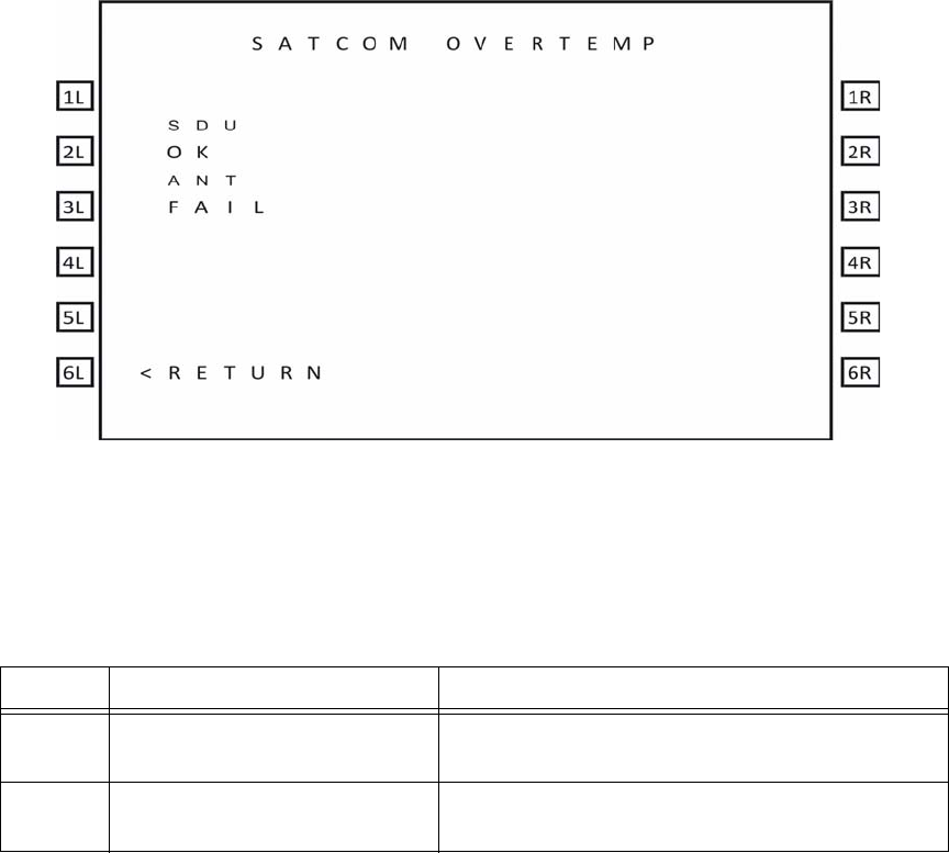
SYSTEM DESCRIPTION, INSTALLATION, AND MAINTENANCE MANUAL
ARINC 781-200 SDU and SCM
23-15-30 4-11
DATE TBD
Figure 4-4 SATCOM Overtemp Menu
Table 4-11 describes the information available on the SATCOM OVERTEMP menu.
D. SCM Health
As shown in Figure 4-5, the SATCOM SCM menu reports the status of the communication
buses to the SCM and the status of the secure and user configuration tables.
Table 4-11 SATCOM OVERTEMP Menu
Label Description Action
SDU Reports the SDU thermal status
as OK or FAIL. If the status is FAIL, check the fan operation and
temperature at the location of the equipment.
HGA Reports the HGA thermal status
as OK, NO DATA, or FAIL. If the status is FAIL, check the fan operation and
temperature at the location of the equipment.
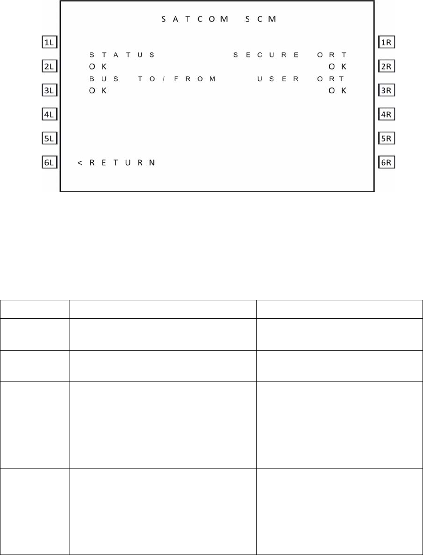
SYSTEM DESCRIPTION, INSTALLATION, AND MAINTENANCE MANUAL
ARINC 781-200 SDU and SCM
23-15-30 4-12
DATE TBD
Figure 4-5 SATCOM SCM Menu
Table 4-12 describes the information available on the SATCOM SCM menu.
Table 4-12 SATCOM SCM Menu
Label Description Action
STATUS Reports the SCM status as OK or FAIL. If the status is FAIL, return the SCM to
RCI the equipment supplier.
BUS
TO/FROM Reports the status of the bus to the SCM as
OK or FAIL. If the status is FAIL, check the
connections to the SCM.
SECURE ORT Reports the status of the Secure ORT as
one of the following:
NOT LOADED – No ORT in SCM memory.
OK – Secure ORT is valid.
INVALID – The Secure ORT is corrupted or
otherwise invalid and must be reloaded.
If the status is INVALID or NOT
LOADED, load a SECURE ORT file.
USER ORT Reports the status of the User ORT as one
of the following:
NOT LOADED – No ORT in SCM memory.
OK – User ORT is valid.
INVALID – The User ORT is corrupted or
otherwise invalid and must be reloaded.
If the status is INVALID or NOT
LOADED, load a USER ORT file.
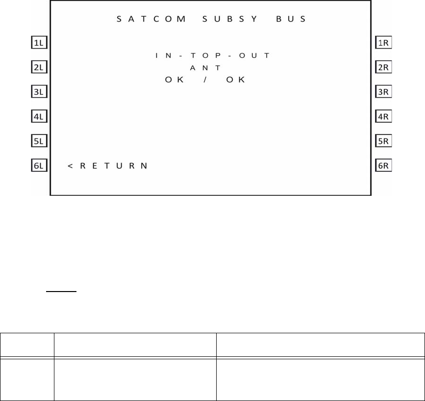
SYSTEM DESCRIPTION, INSTALLATION, AND MAINTENANCE MANUAL
ARINC 781-200 SDU and SCM
23-15-30 4-13
DATE TBD
E. Subsystem Bus Status
As shown in Figure 4-6, the SATCOM SUBSY BUS menu reports the status of all
subsystem buses that provide communication between the components of the system.
Figure 4-6 SATCOM Subsystem Bus Menu
Table 4-13 describes the information available on the SATCOM SUBSY BUS menu.
Fields are left blank if the equipment is not included in the installation.
NOTE: Input and output are with respect to the SDU.
F. RF Path Status
As shown in Figure 4-7, the SATCOM RF PATH menu reports the status the RF paths.
Table 4-13 SATCOM SUBSY BUS Menu
Label Description Action
ANT Reports the status of the input and
output buses for the antenna as OK,
NO DATA, or FAIL.
If status is NO DATA, label 350 is missing—
check the bus connections.
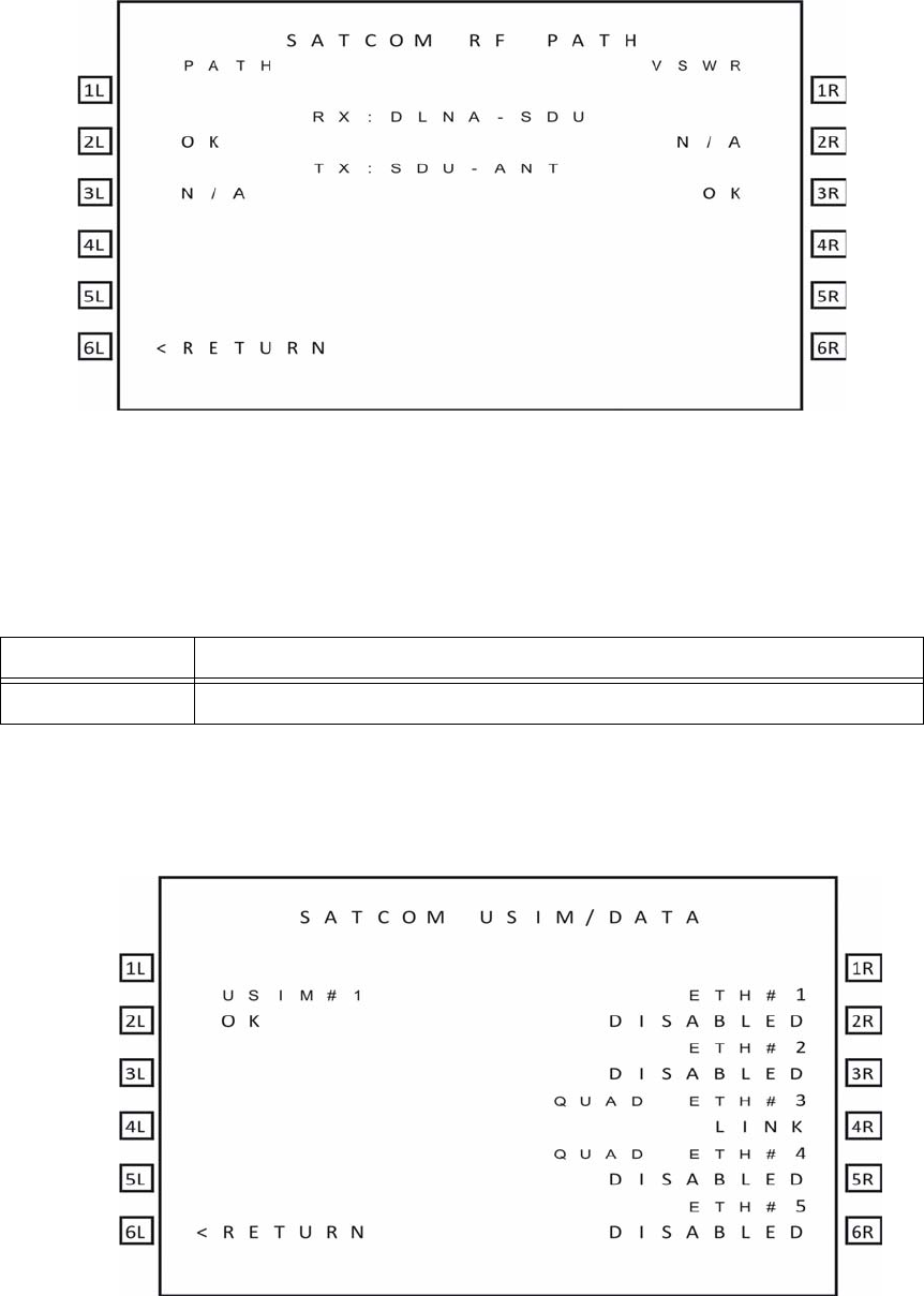
SYSTEM DESCRIPTION, INSTALLATION, AND MAINTENANCE MANUAL
ARINC 781-200 SDU and SCM
23-15-30 4-14
DATE TBD
Figure 4-7 SATCOM RF Path Menu
Table 4-14 describes the information available on the SATCOM RF PATH menu.
G. USIM and Data Bus Status
As shown in Figure 4-8, the SATCOM USIM/DATA menu reports the status of the USIMs
and data buses of the system.
Table 4-14 SATCOM RF PATH Menu
Label Description
RX:DLNA-SDU Reports the status of the RF path from the DLNA to the SDU as OK or FAULT.

SYSTEM DESCRIPTION, INSTALLATION, AND MAINTENANCE MANUAL
ARINC 781-200 SDU and SCM
23-15-30 4-15
DATE TBD
Figure 4-8 SATCOM USIM/DATA Menu
Table 4-15 describes the information available on the USIM/Data menu.
H. ORT
The A781-200 system may not function properly if the ORT parameters do not match the
installed system.
(1) Checking the ORT
You can check the content of the ORT file through the maintenance port menus.
"SDU Maintenance Port Utility (MPU)" on page 4-2 provides information about
accessing the maintenance port menus.
NOTE: The ORT includes many parameters that affect internal operations. These
parameters are not meaningful for technicians troubleshooting the satellite
communication system.
To check the ORT:
1. In the maintenance port menus, navigate to menu 3.
2. To list the ORT, press H.
The list of ORT parameters appears. The list is about eight pages long.
Some ORT parameters displayed are system defaults that cannot be modified
through the secure and user ORT files.
3. Compare the ORT parameters to the system installed in the aircraft.
I. Contact Product Support
When the troubleshooting procedures do not find a fault and the A781-200 system does
not function properly, contact RCI Product Support.
RCI Product Support contact information:
Table 4-15 SATCOM USIM/DATA Menu
Label Description
USIM#1 Reports the status of USIM#1 bus as OK, WARMING, SBB LOG, FAULT, or N/A
if channel card 1 is not in SBB mode.
ETH#1 Reports the status of ETH#1 bus as DISABLED, LINK, or NO LINK.
ETH#2 Reports the status of ETH#2 bus as DISABLED, LINK, or NO LINK.
QUAD ETH#3 Reports the status of QUAD ETH#3 bus as DISABLED, LINK, or NO LINK.
QUAD ETH#4 Reports the status of QUAD ETH#4 bus as DISABLED, LINK, or NO LINK.
ETH#5 Reports the status of ETH#5 bus as DISABLED, LINK, or NO LINK.
NOTE: Ethernet 1, 2, and 5 are not supported. Ethernet 4 is only used for application data loading.

SYSTEM DESCRIPTION, INSTALLATION, AND MAINTENANCE MANUAL
ARINC 781-200 SDU and SCM
23-15-30 4-16
DATE TBD
[RCI to complete]
RCI Product Support may ask you to capture and send them system specific logs and
reports.
To access logs:
1. In the maintenance port menus, navigate to Menu 3.
2. Turn on the text capture feature of the terminal emulator on your computer.
In HyperTerminal, click Transfer, and then click Capture Text.
3. To view the call log, in Menu 3, press F.
4. Turn off the text capture feature of the terminal emulator and send the captured file
to RCI Product Support.
To access reports:
1. Turn on the text capture feature of the terminal emulator on your computer.
In HyperTerminal, click Transfer, and then click Capture Text.
2. In the maintenance port menus, press EQUAL SIGN (=).
A list of reports appears.
3. To activate a report, type the number next to the report description, and then press
ENTER.
NOTE: RCI Product Support will specify the required reports, and may ask you to
operate the A781-200 equipment while the reports gather information.
4. To stop a report, press EQUAL SIGN (=), then type the number of the report, and
then press ENTER.
NOTE: To stop all reports, press X.
5. Turn off the text capture feature of the terminal emulator and send the captured file
to RCI Product Support.
3. Adjustment/Alignment Procedures
There are no adjustment/alignment procedures required for the A781-200 system.
4. Modification History
The A781-200 system currently has no history of modifications.
SYSTEM DESCRIPTION, INSTALLATION, AND MAINTENANCE MANUAL
ARINC 781-200 SDU and SCM
23-15-30 5-1
DATE TBD
MAINTENANCE AND REPAIR
This section provides maintenance and repair information for the A781-200 system, including the
following sections:
• Maintenance
• Repair
• Instructions for Continued Airworthiness
• Visual Inspection and Check
1. Maintenance
The A781-200 system does not require routine maintenance.
2. Repair
If functional problems occur, the SDU BITE identifies the faulty LRU.
As per continued airworthiness instructions, if an SDU or SCM is inoperative, use the Standard
Practices Chapter of the Aircraft Maintenance Manual to:
• remove the unit
• secure cables and wiring
• collar applicable switches and circuit breakers, and placard them as “inoperative”
Before flight, revise the equipment list and weight and balance data as applicable, and record
the removal of the unit in the log book [refer to section 91.213 of the FAR or the aircraft’s minimum
equipment list (MEL)].
All repairs must be performed at the RCI equipment supplier factory.
3. Instructions for Continued Airworthiness
Periodic inspections of the mechanical and electrical interfaces of the A781-200 system
components to the aircraft should be completed as defined by the governing airworthiness
body’s Instructions for Continued Airworthiness (ICA) for the installation (for example, Transport
Canada, the FAA, the EASA).
Installation of the ARINC 781 SATCOM Avionics System on an aircraft by Supplemental Type
Certificate (STC) obligates the aircraft operator to include the maintenance information supplied
by this manual in the operator’s Aircraft Maintenance manual and the operator’s Aircraft
Scheduled Maintenance Program.
This section provides the special instructions and maintenance requirements for continued
airworthiness of the A781-200 system.
SYSTEM DESCRIPTION, INSTALLATION, AND MAINTENANCE MANUAL
ARINC 781-200 SDU and SCM
23-15-30 5-2
DATE TBD
A. Airworthiness Limitations
When applicable, the Airworthiness Limitations section is FAA-approved, and specifies
maintenance required under Title 14 Code of Federal Regulations (CFR) Part 43.16 and
14 CFR 91.403 of the Federal Aviation Regulations unless an alternative program has
been FAA approved.
This section must be added to the Airplane Maintenance Manuals. The information
contained herein supplements the Airplane Maintenance Manuals only in those areas
covered by the A781-200 system installation. For limitations and procedures not
contained in this supplement, consult the basic Airplane Maintenance Manuals.
The inspections and airworthiness limitations specified in this section are FAA approved.
This section specifies the inspections and other maintenance required under sections
433.16 and 91.403 of the Federal Aviation Regulations unless an alternative program
has been FAA approved.
B. Electrical and Mechanical Inspection and Check
Periodic inspections of the mechanical and electrical interfaces of the A781 system
components to the aircraft should be completed as defined by the governing
airworthiness body (for example, Transport Canada, the FAA, the EASA).
C. Instructions for Continued Airworthiness
The following paragraphs describe all maintenance requirements and instructions for
continued airworthiness of the A781-200 system:
1. This manual contains maintenance information for the SDU and SCM, including
system description, system operation, installation, test, and fault isolation.
2. Add the following information to the illustrated parts catalog for the aircraft:
• all part numbers referred to in this manual
• all LRUs referred to in this manual
3. Add all wiring diagram information contained in this manual to the aircraft operator’s
appropriate aircraft Wiring Diagram Manuals.
4. No additional or routine maintenance is required for the on-condition SDU or SCM.
5. If an SDU or SCM is inoperative, follow the instructions listed in "Repair" on page 5-1.
6. Return all units to the RCI equipment supplier factory for repair. See Appendix A:
Return Material Authorization for detailed removal information and procedures.
7. Install repaired units on the aircraft in accordance with the installation instructions
provided in this manual.
8. Make sure that all repaired units are operating before approving them for return to
service, using the operational verification tests and procedures provided in this
manual.
9. Enter the approval for return to service in the logbook, as required by section 43.9
of the FAR.

SYSTEM DESCRIPTION, INSTALLATION, AND MAINTENANCE MANUAL
ARINC 781-200 SDU and SCM
23-15-30 5-3
DATE TBD
10.Add the following scheduled maintenance tasks to the aircraft operator’s appropriate
aircraft maintenance program:
1. Recommended periodic scheduled servicing tasks: None required.
2. Recommended periodic inspections: as per the aircraft inspection and
maintenance schedule.
3. Recommended periodic scheduled preventative maintenance tests (tests to
determine system condition and/or latent failures): None required.
4. Visual Inspection and Check
Perform the following procedures to inspect the SDU and SCM after installation of the units onto
the aircraft.
Follow all approved safety standards and practices during the inspection.
1. Disconnect all circuit breakers to the SDU and SCM and associated systems.
CAUTION: FAILURE TO DISCONNECT CIRCUIT BREAKERS CAN LEAD TO
INJURY TO THE OPERATOR AND DAMAGE TO THE EQUIPMENT.
2. Examine the connection for loose, damaged, or missing hardware.
3. Examine cables and connections. Contact RCI Product Support to gauge the severity
of the damage if you find:
•corrosion
• chafing
• wear
• damage
4. Tighten any loose connectors to the manufacturer’s recommended value.
SYSTEM DESCRIPTION, INSTALLATION, AND MAINTENANCE MANUAL
ARINC 781-200 SDU and SCM
23-15-30 5-4
DATE TBD
Blank Page
SYSTEM DESCRIPTION, INSTALLATION, AND MAINTENANCE MANUAL
ARINC 781-200 SDU and SCM
23-15-30 A-1
DATE TBD
APPENDIX A: RETURN MATERIAL AUTHORIZATION
To return equipment to RCI for repair, this RMA procedure must be followed. Failure to comply with
this procedure may result in shipping delays and additional charges.
1. Warranty Returns
Equipment that qualifies for warranty repair can be returned to RCI for repair or replacement at
their discretion. The customer shall pay the shipping costs to RCI and RCI will pay the shipping
costs to return the repaired/replaced unit to the customer.
2. Non-Warranty Returns
Equipment that fails to work properly because of improper or negligent use, abuse, shipping
damage, or any other condition can still be returned to RCI for repair or replacement at their
discretion. The customer will be notified of the cost to repair or replace the unit before invoicing
for the repair or replacement. The customer shall pay for the shipping costs to and from RCI.
3. Repackaging Requirements
ARINC 781 SDU or SCM components must be returned to RCI in approved shipping containers.
Failure to do so may invalidate the warranty.
If SDU or SCM shipping containers are unavailable, they can be ordered from RCI when
requesting the RMA number.
4. RMA Procedure
If it is determined that equipment must be returned to RCI for repair or overhaul, follow the RMA
procedure below.
1. Have the following information ready before calling RCI Product Support:
• Model (e.g., A781-200 SDU)
• Unit part number (e.g., 1530-A-1100, 1530-A-1300-01 or 1530-A-1300-02)
• Serial number
• Description of failure
• Aircraft tail number, serial number, and aircraft model number
2. Call RCI Product Support at [RCI to complete].
3. An RCI Product Support specialist will attempt to resolve the problem by telephone.
If equipment must be returned to RCI, the Product Support Specialist will authorize
the R&O Coordinator to issue an RMA number.
4. Pack the equipment in the original shipping container or a container approved by RCI.
SYSTEM DESCRIPTION, INSTALLATION, AND MAINTENANCE MANUAL
ARINC 781-200 SDU and SCM
23-15-30 A-2
DATE TBD
5. Write the RMA number on the outside of the shipping container and on all shipping
documents, enclose a copy in the box, and send your prepaid shipment to RCI.
[RCI to complete]
6. Fax or email the details of the shipment to the R&O Coordinator, including the
following information: Shipment date, carrier name, and the waybill number.
7. The processing of LRU returns is limited to standard business hours from 8:30 am
to 5:00 pm EST. For general inquires and status requests, contact the R&O
department directly:
Phone: [RCI to complete]
Email: [RCI to complete]
Fax: [RCI to complete]