EMS Technologies Canada A781-MK4 Aeronautical Satcom Transceiver User Manual 23 15 87
EMS Technologies Canada, Ltd. Aeronautical Satcom Transceiver 23 15 87
UserManual.wiki
>
EMS Technologies Canada
>
A781 MK4 User Manual
User Guide
Navigation menu
Upload a User Manual
Namespaces
Wiki Guide
HTML
PDF
Info
Views
User Manual
Discussion / Help
Navigation


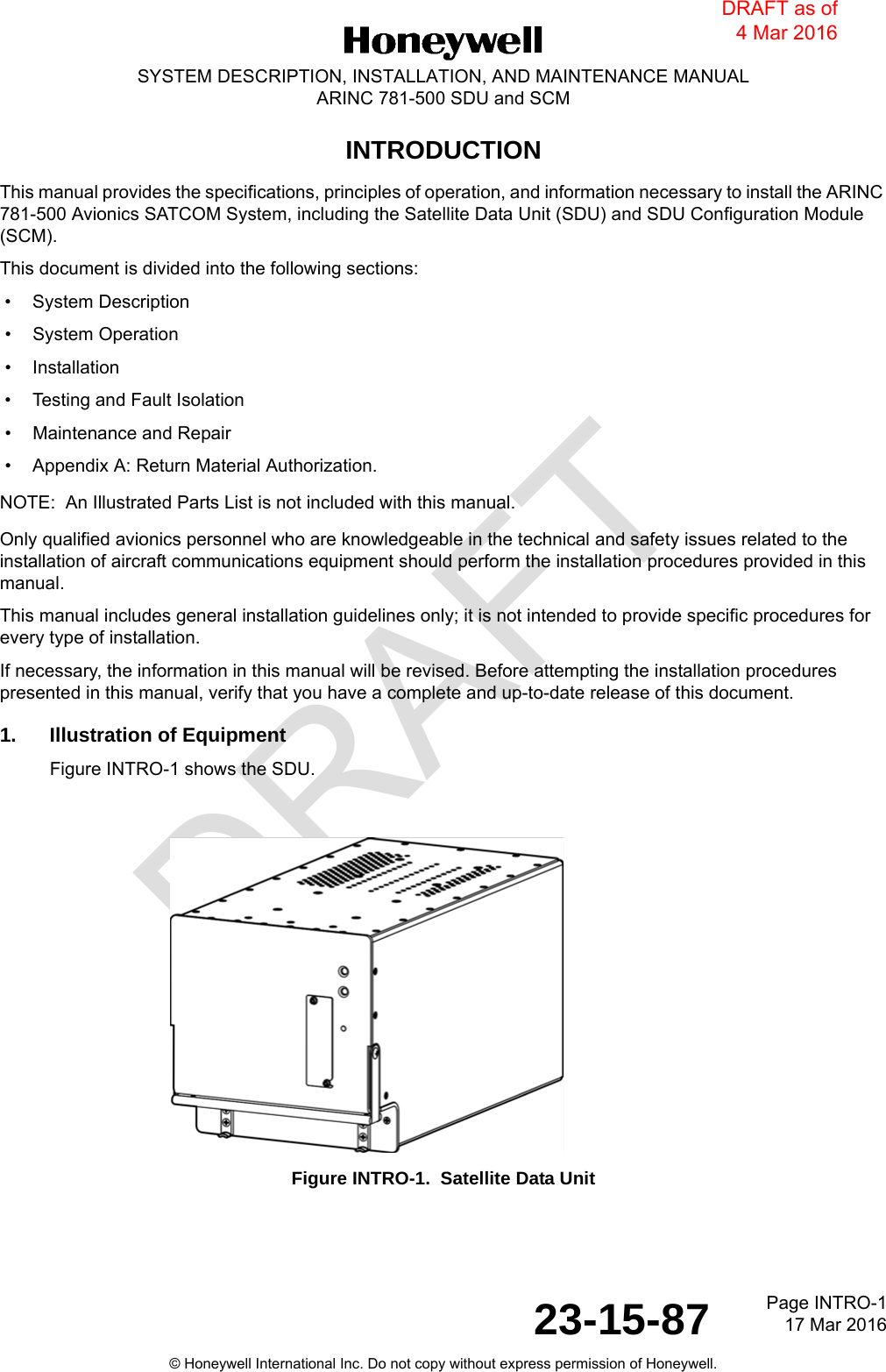


![DRAFTPage A-1 17 Mar 201623-15-87SYSTEM DESCRIPTION, INSTALLATION, AND MAINTENANCE MANUALARINC 781-500 SDU and SCM© Honeywell International Inc. Do not copy without express permission of Honeywell.APPENDIX A: RETURN MATERIAL AUTHORIZATIONTo return equipment to RC for repair, this RMA procedure must be followed. Failure to comply with this procedure may result in shipping delays and additional charges.1. Warranty ReturnsEquipment that qualifies for warranty repair can be returned to RC for repair or replacement at their discretion. The customer shall pay the shipping costs to RC and RC will pay the shipping costs to return the repaired/replaced unit to the customer.2. Non-Warranty ReturnsEquipment that fails to work properly because of improper or negligent use, abuse, shipping damage, or any other condition can still be returned to RC for repair or replacement at their discretion. The customer will be notified of the cost to repair or replace the unit before invoicing for the repair or replacement. The customer shall pay for the shipping costs to and from RC.3. Repackaging RequirementsARINC 781 SDU or SCM components must be returned to RC in approved shipping containers. Failure to do so may invalidate the warranty.If SDU or SCM shipping containers are unavailable, they can be ordered from RC when requesting the RMA number.4. RMA ProcedureIf it is determined that equipment must be returned to RC for repair or overhaul, follow the RMA procedure below. 1. Have the following information ready before calling RC Product Support:• Model (e.g., A781-500 SDU)•Unit part number (e.g., 90402750, 90404775)• Serial number• Description of failure• Aircraft tail number, serial number, and aircraft model number 2. An RC Product Support specialist will attempt to resolve the problem by telephone. If equipment must be returned to RC, the Product Support Specialist will authorize the R&O Coordinator to issue an RMA number. 3. Pack the equipment in the original shipping container or a container approved by RC. 4. Write the RMA number on the outside of the shipping container and on all shipping documents, enclose a copy in the box, and send your prepaid shipment to RC.[RC to complete] 5. Fax or email the details of the shipment to the R&O Coordinator, including the following information: Shipment date, carrier name, and the waybill number.DRAFT as of 4 Mar 2016](https://usermanual.wiki/EMS-Technologies-Canada/A781-MK4/User-Guide-2992562-Page-115.png)
![DRAFTPage A-2 17 Mar 201623-15-87© Honeywell International Inc. Do not copy without express permission of Honeywell.SYSTEM DESCRIPTION, INSTALLATION, AND MAINTENANCE MANUALARINC 781-500 SDU and SCM 6. The processing of LRU returns is limited to standard business hours from 8:30 am to 5:00 pm EST. For general inquires and status requests, contact the R&O department directly:Phone: [RC to complete]Email: [RC to complete]Fax: [RC to complete]DRAFT as of 4 Mar 2016](https://usermanual.wiki/EMS-Technologies-Canada/A781-MK4/User-Guide-2992562-Page-116.png)