EMS Technologies Canada A781-MK4 Aeronautical Satcom Transceiver User Manual 23 15 87
EMS Technologies Canada, Ltd. Aeronautical Satcom Transceiver 23 15 87
User Guide

DRAFT
Honeywell International Inc.
400 Maple Grove Road
Ottawa, Ontario, K2V 1B8
Canada
CAGE: 38473
Telephone: 800-601-3099 (Toll Free U.S.A./Canada)
Telephone: 602-365-3099 (International Direct)
Website: www.myaerospace.com
TITLE PAGE-1
Publication Number D201601000025, Revision 0 Initial 17 Mar 2016
© Honeywell International Inc. Do not copy without express permission of Honeywell.
23-15-87
This document contains technical data and is subject to U.S. export regulations. These commodities,
technology, or software were exported from the United States in accordance with the export administration
regulations. Diversion contrary to U.S. law is prohibited.
ECCN: 9E991.
ARINC 781-500 SDU and SCM
System Description, Installation, and Maintenance Manual
D201601000025, Revision 0
This document provides procedures for the equipment listed below.
Model Part Number
ARINC 781-500 Satellite Data Unit 90402750
ARINC 781-500 SDU Configuration Module - Single
SBB
90404775
DRAFT as of
4 Mar 2016

DRAFT
TITLE PAGE-2
17 Mar 2016
23-15-87
SYSTEM DESCRIPTION, INSTALLATION, AND MAINTENANCE MANUAL
ARINC 781-500 SDU and SCM
© Honeywell International Inc. Do not copy without express permission of Honeywell.
Proprietary Information
Honeywell – Confidential
THIS COPYRIGHTED WORK AND ALL INFORMATION ARE THE PROPERTY OF HONEYWELL
INTERNATIONAL INC., CONTAIN TRADE SECRETS AND MAY NOT, IN WHOLE OR IN PART,
BE USED, DUPLICATED, OR DISCLOSED FOR ANY PURPOSE WITHOUT PRIOR WRITTEN
PERMISSION OF HONEYWELL INTERNATIONAL INC. ALL RIGHTS RESERVED.
Honeywell Materials License Agreement
The documents and information contained herein (“the Materials”) are the proprietary data of
Honeywell International Inc. These Materials are provided for the exclusive use of Honeywell Service
Centers; Honeywell-authorized repair facilities; operators of Honeywell aerospace products subject
to an applicable product support agreement, their wholly owned-subsidiaries or a formally
designated third party service provider; and direct recipients of Materials from Honeywell’s
Aerospace Technical Publication Distribution. The terms and conditions of this License Agreement
govern your use of these Materials, except to the extent that any terms and conditions of another
applicable agreement with Honeywell regarding the operation, maintenance, or repair of Honeywell
aerospace products conflict with the terms and conditions of this License Agreement, in which case
the terms and conditions of the other agreement will govern. However, this License Agreement will
govern in the event of a conflict between its terms and conditions and those of a purchase order or
acknowledgement.
1. License Grant - If you are a party to an applicable product support agreement, a Honeywell
Service Center agreement, or an authorized repair facility agreement, Honeywell hereby grants you
a limited, non-exclusive license to use these Materials to operate, maintain, or repair Honeywell
aerospace products only in accordance with that agreement.
If you are a direct recipient of these Materials from Honeywell’s Aerospace Technical Publication
Distribution and are not a party to an agreement related to the operation, maintenance or repair of
Honeywell aerospace products, Honeywell hereby grants you a limited, non-exclusive license to
use these Materials to maintain or repair the subject Honeywell aerospace products only at the
facility to which these Materials have been shipped ("the Licensed Facility"). Transfer of the
Materials to another facility owned by you is permitted only if the original Licensed Facility retains
no copies of the Materials and you provide prior written notice to Honeywell.
2. Rights In Materials - Honeywell retains all rights in these Materials and in any copies thereof that
are not expressly granted to you, including all rights in patents, copyrights, trademarks, and trade
secrets. No license to use any Honeywell trademarks or patents is granted under this License
Agreement.
3. Confidentiality - You acknowledge that these Materials contain information that is confidential
and proprietary to Honeywell. You agree to take all reasonable efforts to maintain the confidentiality
of these Materials.
4. Assignment And Transfer - This License Agreement may be assigned to a formally designated
service designee or transferred to a subsequent owner or operator of an aircraft containing the
subject Honeywell aerospace products. However, the recipient of any such assignment or transfer
must assume all of your obligations under this License Agreement. No assignment or transfer shall
relieve any party of any obligation that such party then has hereunder.
5. Copies of Materials - Unless you have the express written permission of Honeywell, you may
not make or permit making of copies of the Materials. Notwithstanding the foregoing, you may make
copies of only portions of the Material for your internal use. You agree to return the Materials and
any copies thereof to Honeywell upon the request of Honeywell.
DRAFT as of
4 Mar 2016

DRAFT
TITLE PAGE-3
17 Mar 2016
23-15-87
SYSTEM DESCRIPTION, INSTALLATION, AND MAINTENANCE MANUAL
ARINC 781-500 SDU and SCM
© Honeywell International Inc. Do not copy without express permission of Honeywell.
6. Term - This License Agreement is effective until terminated as set forth herein. This License
Agreement will terminate immediately, without notice from Honeywell, if you fail to comply with any
provision of this License Agreement or will terminate simultaneously with the termination or
expiration of your applicable product support agreement, authorized repair facility agreement, or
your formal designation as a third party service provider. Upon termination of this License
Agreement, you will return these Materials to Honeywell without retaining any copies and will have
one of your authorized officers certify that all Materials have been returned with no copies retained.
7. Remedies - Honeywell reserves the right to pursue all available remedies and damages resulting
from a breach of this License Agreement.
8. Limitation of Liability - Honeywell does not make any representation regarding the use or
sufficiency of the Materials. THERE ARE NO OTHER WARRANTIES, WHETHER WRITTEN OR
ORAL, EXPRESS, IMPLIED OR STATUTORY, INCLUDING, BUT NOT LIMITED TO, (i)
WARRANTIES ARISING FROM COURSE OF PERFORMANCE, DEALING, USAGE, OR TRADE,
WHICH ARE HEREBY EXPRESSLY DISCLAIMED, OR (ii) WARRANTIES AGAINST
INFRINGEMENT OF INTELLECTUAL PROPERTY RIGHTS OF THIRD PARTIES, EVEN IF
HONEYWELL HAS BEEN ADVISED OF ANY SUCH INFRINGEMENT. IN NO EVENT WILL
HONEYWELL BE LIABLE FOR ANY INCIDENTAL DAMAGES, CONSEQUENTIAL DAMAGES,
SPECIAL DAMAGES, INDIRECT DAMAGES, LOSS OF PROFITS, LOSS OF REVENUES, OR
LOSS OF USE, EVEN IF INFORMED OF THE POSSIBILITY OF SUCH DAMAGES. TO THE
EXTENT PERMITTED BY APPLICABLE LAW, THESE LIMITATIONS AND EXCLUSIONS WILL
APPLY REGARDLESS OF WHETHER LIABILITY ARISES FROM BREACH OF CONTRACT,
WARRANTY, TORT (INCLUDING BUT NOT LIMITED TO NEGLIGENCE), BY OPERATION OF
LAW, OR OTHERWISE.
9. Controlling Law - This License shall be governed and construed in accordance with the laws of
the State of New York without regard to the conflicts of laws provisions thereof. This license sets
forth the entire agreement between you and Honeywell and may only be modified by a writing duly
executed by the duly authorized representatives of the parties.
Safety Advisory
WARNING: BEFORE THE MATERIALS CALLED OUT IN THIS PUBLICATION ARE USED, KNOW
THE HANDLING, STORAGE AND DISPOSAL PRECAUTIONS RECOMMENDED BY THE
MANUFACTURER OR SUPPLIER. FAILURE TO OBEY THE MANUFACTURERS’ OR
SUPPLIERS’ RECOMMENDATIONS CAN RESULT IN PERSONAL INJURY OR DISEASE.
This publication describes physical and chemical processes which can make it necessary to use
chemicals, solvents, paints, and other commeRCally available materials. The user of this publication
must get the Material Safety Data Sheets (OSHA Form 174 or equivalent) from the manufacturers
or suppliers of the materials to be used. The user must know the manufacturer/ supplier data and
obey the procedures, recommendations, warnings and cautions set forth for the safe use, handling,
storage, and disposal of the materials.
Warranty/Liability Advisory
WARNING: HONEYWELL ASSUMES NO RESPONSIBILITY FOR ANY HONEYWELL
EQUIPMENT WHICH IS NOT MAINTAINED AND/OR REPAIRED IN ACCORDANCE WITH
HONEYWELL’S PUBLISHED INSTRUCTIONS AND/OR HONEYWELL’S FAA/SFAR 36 REPAIR
AUTHORIZATION. NEITHER DOES HONEYWELL ASSUME RESPONSIBILITY FOR SPECIAL
TOOLS AND TEST EQUIPMENT FABRICATED BY COMPANIES OTHER THAN HONEYWELL.
DRAFT as of
4 Mar 2016

DRAFT
TITLE PAGE-4
17 Mar 2016
23-15-87
SYSTEM DESCRIPTION, INSTALLATION, AND MAINTENANCE MANUAL
ARINC 781-500 SDU and SCM
© Honeywell International Inc. Do not copy without express permission of Honeywell.
WARNING: INCORRECTLY REPAIRED COMPONENTS CAN AFFECT AIRWORTHINESS OR
DECREASE THE LIFE OF THE COMPONENTS. INCORRECTLY FABRICATED SPECIAL
TOOLING OR TEST EQUIPMENT CAN RESULT IN DAMAGE TO THE PRODUCT
COMPONENTS OR GIVE UNSATISFACTORY RESULTS.
Copyright - Notice
Copyright 2016 Honeywell International Inc. All rights reserved.
Honeywell is a registered trademark of Honeywell International Inc.
All other marks are owned by their respective companies.
ARINC 781-500 SDU and SCM SDIM
Document Number: D201601000025, Revision 0
Our products are under continuous research and development. Any information may therefore be
changed without prior notice. Honeywell reserves the right to make improvements or changes in
the product described in this manual at any time without notice. While reasonable efforts have been
made in the preparation of this document to assure its accuracy, Honeywell assumes no liability
resulting from any errors or omissions in this document, or from the use of the information contained
herein.
Honeywell International Inc.
400 Maple Grove Road
Ottawa, Ontario, K2V 1B8
Canada
Reception: 613-591-9064
Product Support: Aerospace Technical Support
1-855-808-6500 (U.S. and Canada) or +1-602-365-6500
(International)
Email: AeroTechSupport@Honeywell.com
Revision Table
Revision ECO Description
0 NA First release.
DRAFT as of
4 Mar 2016
DRAFT
Page TI-1
17 Mar 2016
23-15-87
SYSTEM DESCRIPTION, INSTALLATION, AND MAINTENANCE MANUAL
ARINC 781-500 SDU and SCM
© Honeywell International Inc. Do not copy without express permission of Honeywell.
TRANSMITTAL INFORMATION
REVISION 0 DATED 17 MAR 2016
THIS IS AN INITIAL RELEASE OF ARINC 781-500 SDU and SCM SDIMM, ATA NO. 23-15-87, ISSUED FOR
USE IN SUPPORT OF THE FOLLOWING:
Table TI-1 shows the applicable components.
Revision History
Table TI-2 shows the revision history of this SDIMM.
Table TI-1. Applicable Components
Component PN Nomenclature
90402750 ARINC 781-500 Satellite Data Unit
90404775 ARINC 781-500 SDU Configuration Module - Single SBB
Table TI-2. Revision History
Revision Revision Date
0 17 Mar 2016
DRAFT as of
4 Mar 2016

DRAFT
SYSTEM DESCRIPTION, INSTALLATION, AND MAINTENANCE MANUAL
ARINC 781-500 SDU and SCM
Page TI-2
17 Mar 2016
23-15-87
© Honeywell International Inc. Do not copy without express permission of Honeywell.
Blank Page
DRAFT as of
4 Mar 2016

DRAFT
Page RR-1
17 Mar 2016
23-15-87
SYSTEM DESCRIPTION, INSTALLATION, AND MAINTENANCE MANUAL
ARINC 781-500 SDU and SCM
© Honeywell International Inc. Do not copy without express permission of Honeywell.
RECORD OF REVISIONS
When revisions are received, insert revised pages, record the date, and initial.
Revision Number Issue Date Date Inserted Inserted by (initial)
DRAFT as of
4 Mar 2016

DRAFT
SYSTEM DESCRIPTION, INSTALLATION, AND MAINTENANCE MANUAL
ARINC 781-500 SDU and SCM
Page RR-2
17 Mar 2016
23-15-87
© Honeywell International Inc. Do not copy without express permission of Honeywell.
Blank Page
DRAFT as of
4 Mar 2016

DRAFT
Page SBL-1
17 Mar 2016
23-15-87
SYSTEM DESCRIPTION, INSTALLATION, AND MAINTENANCE MANUAL
ARINC 781-500 SDU and SCM
© Honeywell International Inc. Do not copy without express permission of Honeywell.
SERVICE BULLETIN LIST
Service Bulletin
Number Subject Manual Rev.
Number Manual Rev.
Date
DRAFT as of
4 Mar 2016

DRAFT
Page SBL-2
17 Mar 2016
23-15-87
© Honeywell International Inc. Do not copy without express permission of Honeywell.
Blank Page
SYSTEM DESCRIPTION, INSTALLATION, AND MAINTENANCE MANUAL
ARINC 781-500 SDU and SCM
DRAFT as of
4 Mar 2016

DRAFT
Page LEP-1
17 Mar 2016
23-15-87
SYSTEM DESCRIPTION, INSTALLATION, AND MAINTENANCE MANUAL
ARINC 781-500 SDU and SCM
© Honeywell International Inc. Do not copy without express permission of Honeywell.
LIST OF EFFECTIVE PAGES
F indicates a right foldout page with a blank back.
Section Page Date
Title Page T-1 thru T-4 17 Mar 2016
Transmittal Information TI-1 thru TI-4 17 Mar 2016
Record of Revisions RR-1 thru RR-2 17 Mar 2016
Service Bulletin List SBL-1 thru SBL-2 17 Mar 2016
List of Effective Pages LEP-1 thru LEP-2 17 Mar 2016
Table of Contents TC-1 thru TC-2 17 Mar 2016
List of Figures TC-3 thru TC-4 17 Mar 2016
List of Tables TC-5 thru TC-6 17 Mar 2016
Introduction INTRO-1 thru INTRO-6 17 Mar 2016
System Description 1-1 thru 1-10 17 Mar 2016
System Operation 2-1 thru 17 Mar 2016
Installation 3-1 thru 3-28 17 Mar 2016
Testing and Fault Isolation 4-1 thru 4-18 17 Mar 2016
Maintenance and Repair 5-1 thru 5-4 17 Mar 2016
Appendix A: Return Material
Authorization
A-1 thru A-2 17 Mar 2016
DRAFT as of
4 Mar 2016

DRAFT
Page LEP-2
17 Mar 2016
23-15-87
© Honeywell International Inc. Do not copy without express permission of Honeywell.
Blank Page
SYSTEM DESCRIPTION, INSTALLATION, AND MAINTENANCE MANUAL
ARINC 781-500 SDU and SCM
DRAFT as of
4 Mar 2016

DRAFT
Page TC-1
17 Mar 2016
23-15-87
SYSTEM DESCRIPTION, INSTALLATION, AND MAINTENANCE MANUAL
ARINC 781-500 SDU and SCM
© Honeywell International Inc. Do not copy without express permission of Honeywell.
TABLE OF CONTENTS
Title Page
INTRODUCTION
1. Illustration of Equipment ......................................................................................................INTRO-1
2. Acronyms and Abbreviations ...............................................................................................INTRO-2
3. Safety Advisories .................................................................................................................INTRO-4
SYSTEM DESCRIPTION
1. Inmarsat System Overview ........................................................................................................... 1-1
2. Equipment Overview..................................................................................................................... 1-2
3. Equipment Specifications.............................................................................................................. 1-4
4. System Interfaces ......................................................................................................................... 1-7
5. User Interfaces ............................................................................................................................. 1-8
6. Software Description...................................................................................................................1-10
SYSTEM OPERATION
1. Registering and Activating Terminals............................................................................................2-1
2. Using the A781-500 System .........................................................................................................2-2
3. Channel Status and System Configuration ................................................................................. 2-16
4. Maintenance Mode ..................................................................................................................... 2-22
INSTALLATION
1. Advisories ..................................................................................................................................... 3-1
2. Pre-Installation Inspection............................................................................................................. 3-1
3. Installation Procedure ................................................................................................................... 3-1
4. Connection Details........................................................................................................................ 3-2
5. Owners Requirements Table (ORT)..............................................................................................3-7
6. Passive Intermodulation (PIM) Test .............................................................................................. 3-7
7. Installation and Engineering Drawings........................................................................................ 3-11
TESTING AND FAULT ISOLATION
1. Operational and Diagnostic Testing .............................................................................................. 4-1
2. Troubleshooting and Fault Isolation..............................................................................................4-8
3. Adjustment/Alignment Procedures .............................................................................................4-18
4. Modification History ....................................................................................................................4-18
MAINTENANCE AND REPAIR
1. Maintenance .................................................................................................................................5-1
2. Repair ........................................................................................................................................... 5-1
3. Instructions for Continued Airworthiness ......................................................................................5-1
4. Visual Inspection and Check.........................................................................................................5-3
APPENDIX A: RETURN MATERIAL AUTHORIZATION
1. Warranty Returns......................................................................................................................... A-1
2. Non-Warranty Returns ................................................................................................................. A-1
DRAFT as of
4 Mar 2016

DRAFT
SYSTEM DESCRIPTION, INSTALLATION, AND MAINTENANCE MANUAL
ARINC 781-500 SDU and SCM
Page TC-2
17 Mar 2016
23-15-87
© Honeywell International Inc. Do not copy without express permission of Honeywell.
3. Repackaging Requirements......................................................................................................... A-1
4. RMA Procedure ........................................................................................................................... A-1
DRAFT as of
4 Mar 2016

DRAFT
Page TC-5
17 Mar 2016
23-15-87
SYSTEM DESCRIPTION, INSTALLATION, AND MAINTENANCE MANUAL
ARINC 781-500 SDU and SCM
© Honeywell International Inc. Do not copy without express permission of Honeywell.
LIST OF FIGURES
Figure INTRO-1. Satellite Data Unit ...............................................................................................INTRO-1
Figure INTRO-2. SDU Configuration Module .................................................................................INTRO-2
Figure 1-1. Simplified Aeronautical Satellite Communications System .......................................... 1-2
Figure 1-2. A781-500 Avionics System .......................................................................................... 1-3
Figure 1-3. A781-500 Avionics System Block Diagram..................................................................1-7
Figure 2-1. TCP Screen..................................................................................................................2-3
Figure 2-2. A781-500 TCP Menu Structure.................................................................................... 2-4
Figure 2-3. SBB Menu .................................................................................................................. 2-16
Figure 2-4. SATCOM LOG 2 menu ..............................................................................................2-18
Figure 2-5. SATCOM CONFIG 1 menu........................................................................................ 2-19
Figure 2-6. SATCOM CONFIG 2 menu........................................................................................ 2-20
Figure 2-7. SATCOM CONFIG 3 menu........................................................................................ 2-21
Figure 2-8. SATCOM CONFIG 4 menu........................................................................................ 2-21
Figure 2-9. SATCOM CONFIG 5 Menu........................................................................................ 2-22
Figure 2-10. Maintenance Mode TCP Menu Structure................................................................... 2-23
Figure 2-11. SATCOM PARMS ...................................................................................................... 2-26
Figure 2-12. SATCOM OPTIONS................................................................................................... 2-27
Figure 2-13. CONFIG AUDIO 1/2...................................................................................................2-28
Figure 2-14. CONFIG AUDIO 2/2...................................................................................................2-29
Figure 3-1. Top Plug Pin Deviations............................................................................................... 3-4
Figure 3-2. Mid Plug Pin Deviations ...............................................................................................3-5
Figure 3-3. A781-500 SDU Outline and Installation Drawing, PN 90402752 (Sheet 1 of 3) ........3-13
Figure 3-4. A781-500 SDU Outline and Installation Drawing, PN 90402752 (Sheet 2 of 3) ........3-15
Figure 3-5. A781-500 SDU Outline and Installation Drawing, PN 90402752 (Sheet 3 of 3) ........3-17
Figure 3-6. A781-500 SCM Outline and Installation Drawing, PN 90404776 (Sheet 1 of 2) ........3-19
Figure 3-7. A781-500 SCM Outline and Installation Drawing, PN 90404776 (Sheet 2 of 2) ........3-21
Figure 3-8. A781-500 System Interconnect Drawing, PN 90402748 (Sheet 1 of 3)..................... 3-23
DRAFT as of
4 Mar 2016

DRAFT
SYSTEM DESCRIPTION, INSTALLATION, AND MAINTENANCE MANUAL
ARINC 781-500 SDU and SCM
Page TC-6
17 Mar 2016
23-15-87
© Honeywell International Inc. Do not copy without express permission of Honeywell.
Figure 3-9. A781-500 System Interconnect Drawing, PN 90402748 (Sheet 2 of 3)..................... 3-25
Figure 3-10. A781-500 System Interconnect Drawing, PN 90402748 (Sheet 3 of 3)..................... 3-27
Figure 4-1. Maintenance Cable ......................................................................................................4-2
Figure 4-2. SATCOM Subsystem Health Menu.............................................................................. 4-9
Figure 4-3. SATCOM System Bus Menu...................................................................................... 4-10
Figure 4-4. SATCOM Overtemp Menu .........................................................................................4-12
Figure 4-5. SATCOM SCM Menu................................................................................................. 4-13
Figure 4-6. SATCOM Subsystem Bus Menu................................................................................4-14
Figure 4-7. SATCOM RF Path Menu............................................................................................ 4-15
Figure 4-8. SATCOM USIM/DATA Menu ..................................................................................... 4-16
DRAFT as of
4 Mar 2016

DRAFT
Page TC-7
17 Mar 2016
23-15-87
SYSTEM DESCRIPTION, INSTALLATION, AND MAINTENANCE MANUAL
ARINC 781-500 SDU and SCM
© Honeywell International Inc. Do not copy without express permission of Honeywell.
LIST OF TABLES
Table Page
Table 1-1. SDU Physical Characteristics and Specifications ........................................................1-4
Table 1-2. SCM Physical Characteristics and Specifications........................................................ 1-5
Table 1-3. ARINC 781-500 SDU and SCM ERTCA/DO-160E Environmental Characteristics ..... 1-5
Table 1-4. SDU System Interfaces................................................................................................1-8
Table 1-5. SDU LED Status ..........................................................................................................1-9
Table 2-1. A781-500 System Log Status ...................................................................................... 2-6
Table 2-2. SBB Menu .................................................................................................................. 2-17
Table 2-3. SATCOM LOG 2 Menu .............................................................................................. 2-18
Table 2-4. SATCOM CONFIG 1 Menu........................................................................................ 2-19
Table 2-5. SATCOM CONFIG 2 Menu........................................................................................ 2-20
Table 2-6. SATCOM CONFIG 3 Menu........................................................................................ 2-21
Table 2-7. SATCOM CONFIG 4 Menu........................................................................................ 2-22
Table 2-8. SATCOM CONFIG 8 Menu........................................................................................ 2-22
Table 2-7. SATCOM PARMS Menu ............................................................................................ 2-26
Table 2-8. SATCOM OPTIONS Menu......................................................................................... 2-27
Table 2-9. SATCOM CONFIG AUDIO 1 Menu ........................................................................... 2-28
Table 2-10. SATCOM CONFIG AUDIO 2 Menu ........................................................................... 2-29
Table 3-1. SDU Rear Connector Pin Deviations ........................................................................... 3-2
Table 3-2. SDU Front Connector DSUB and RJ45 Pin Assignment .............................................3-6
Table 3-3. SCM D-Type Connector Pin Assignment.....................................................................3-6
Table 3-4. PIM Test Conditions.....................................................................................................3-9
Table 4-1 List of Required Test Equipment..................................................................................4-2
Table 4-2 Maintenance Port Connection Settings........................................................................ 4-3
Table 4-3 Menu 1 Item Descriptions ............................................................................................ 4-4
Table 4-4 Menu 2 Item Descriptions ............................................................................................ 4-4
Table 4-5 Menu 3 Item Descriptions ............................................................................................ 4-5
DRAFT as of
4 Mar 2016

DRAFT
Page TC-8
17 Mar 2016
23-15-87
© Honeywell International Inc. Do not copy without express permission of Honeywell.
SYSTEM DESCRIPTION, INSTALLATION, AND MAINTENANCE MANUAL
ARINC 781-500 SDU and SCM
Table 4-6 Test Setup Procedure ..................................................................................................4-6
Table 4-7 Power-On Test Procedure ........................................................................................... 4-7
Table 4-8 Power-On Test Procedure ........................................................................................... 4-7
Table 4-9 Post Test Procedure .................................................................................................... 4-8
Table 4-10 SATCOM Subsystem Health Menu.............................................................................. 4-9
Table 4-11 Bus Status Indicators .................................................................................................4-11
Table 4-12 SATCOM OVERTEMP Menu..................................................................................... 4-12
Table 4-13 SATCOM SCM Menu................................................................................................. 4-13
Table 4-14 SATCOM SUBSY BUS Menu .................................................................................... 4-14
Table 4-15 SATCOM RF PATH Menu ......................................................................................... 4-15
Table 4-16 SATCOM USIM/DATA Menu ..................................................................................... 4-16
DRAFT as of
4 Mar 2016

DRAFT
Page INTRO-1
17 Mar 2016
23-15-87
SYSTEM DESCRIPTION, INSTALLATION, AND MAINTENANCE MANUAL
ARINC 781-500 SDU and SCM
© Honeywell International Inc. Do not copy without express permission of Honeywell.
INTRODUCTION
This manual provides the specifications, principles of operation, and information necessary to install the ARINC
781-500 Avionics SATCOM System, including the Satellite Data Unit (SDU) and SDU Configuration Module
(SCM).
This document is divided into the following sections:
• System Description
• System Operation
• Installation
• Testing and Fault Isolation
• Maintenance and Repair
• Appendix A: Return Material Authorization.
NOTE: An Illustrated Parts List is not included with this manual.
Only qualified avionics personnel who are knowledgeable in the technical and safety issues related to the
installation of aircraft communications equipment should perform the installation procedures provided in this
manual.
This manual includes general installation guidelines only; it is not intended to provide specific procedures for
every type of installation.
If necessary, the information in this manual will be revised. Before attempting the installation procedures
presented in this manual, verify that you have a complete and up-to-date release of this document.
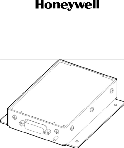
1. Illustration of Equipment
Figure INTRO-1 shows the SDU.
Figure INTRO-1. Satellite Data Unit
DRAFT as of
4 Mar 2016
DRAFT
Page INTRO-2
17 Mar 2016
23-15-87
© Honeywell International Inc. Do not copy without express permission of Honeywell.
SYSTEM DESCRIPTION, INSTALLATION, AND MAINTENANCE MANUAL
ARINC 781-500 SDU and SCM
Figure INTRO-2 shows the SCM.
Figure INTRO-2. SDU Configuration Module
2. Acronyms and Abbreviations
AES Aircraft Earth Station
AMSS Aeronautical Mobile Satellite Services
AORE Atlantic Ocean Region-East
AORW Atlantic Ocean Region-West
APAC Asia-Pacific
BIT Built-In-Test
BITE Built-In-Test Equipment
BSU Beam Steering Unit
CEPT Comite Europeen des Postes et Telecommunications
CTU Cabin Telecommunications Unit
DLNA Diplexer/Low-Noise Amplifier
DITS Digital Information Transfer System
EASA European Aviation Safety Agency
EMEA Europe, Middle East, and Africa
ESD Electrostatic Discharge
FAA Federal Aviation Administration
FAR Federal Aviation Regulation
FMS Flight Management System
DRAFT as of
4 Mar 2016

DRAFT
Page INTRO-3
17 Mar 2016
23-15-87
SYSTEM DESCRIPTION, INSTALLATION, AND MAINTENANCE MANUAL
ARINC 781-500 SDU and SCM
© Honeywell International Inc. Do not copy without express permission of Honeywell.
GES Ground Earth Station
GND Ground
HGA High Gain Antenna
HPA High Power Amplifier
ICA Instructions for Continued Airworthiness
ICAO lnternational Civil Aviation Organization
I/O Input/Output
IOR Indian Ocean Region
IRS Inertial Reference System
ISDN Integrated Services Digital Network
LES Land Earth Station
LRU Line Replaceable Unit
MCU Modular Concept Unit
MES Mobile Earth Station
MHz Megahertz
MOPS Minimum Operational Performance Standards
MPU Maintenance Port Utility
ORT Owner Requirement Table
POR Pacific Ocean Region
POTS Plain Old Telephone System
RF Radio Frequency
RMA Return Material Authorization
RTN Return
Rx Receive
SATCOM Satellite Communications
SBB SwiftBroadband (Inmarsat)
SCM SDU Configuration Module
SDU Satellite Data Unit
SLU Software Logical Unit
DRAFT as of
4 Mar 2016

DRAFT
Page INTRO-4
17 Mar 2016
23-15-87
© Honeywell International Inc. Do not copy without express permission of Honeywell.
SYSTEM DESCRIPTION, INSTALLATION, AND MAINTENANCE MANUAL
ARINC 781-500 SDU and SCM
3. Safety Advisories
Warnings, cautions, and notes in this manual provide the reader with the following information:
• A WARNING describes an operation, procedure, or condition that, if not obeyed, could cause injury or
death.
• A CAUTION describes an operation, procedure, or condition that, if not obeyed, could cause damage
to the equipment.
• A NOTE provides supplementary information or explanatory text that makes it easier to understand and
perform procedures.
All personnel who install, operate, and maintain the ARINC 781-500 SDU and SCM, and associated test
equipment must know and obey the safety precautions listed below. The procedures provided in this
manual assume that the person performing installation or maintenance tasks is familiar with and obeys
standard aviation shop and safety practices.
The general safety advisories include the following:
WARNING: RADIO FREQUENCY EXPOSURE. OCCUPATIONAL/CONTROLLED EXPOSURE LIMITS
APPLY IN SITUATIONS IN WHICH PERSONS ARE EXPOSED TO RADIO FREQUENCY
ENERGY AS A CONSEQUENCE OF THEIR EMPLOYMENT. THE RADIO SYSTEM
INTEGRATOR SHALL ENSURE OCCUPATIONAL WORKERS ARE FULLY AWARE OF
THE POTENTIAL FOR EXPOSURE AND ARE TRAINED TO EXERCSE CONTROL OVER
THEIR EXPOSURE AS REQUIRED IN THE FOLLOWING REFERENCES: FCC CFR 47,
PART 1.1310, PART 2, 1093; ·INDUSTRY CANADA RSS-102, HEALTH CANADA SAFETY
CODE 6; EUROPEAN DIRECTIVE 2004/40/EC.
WARNING: BEFORE HANDLING ANY UNIT OR COMPONENT, GROUND THE REPAIR OPERATOR
THROUGH A CONDUCTIVE WRIST STRAP OR OTHER DEVICE THAT USES A 470
KILOHM OR 1 MEGAOHM SERIES RESISTOR TO PREVENT INJURY.
CAUTION: TURN OFF POWER BEFORE DISCONNECTING ANY EQUIPMENT FROM WIRING.
DISCONNECTING THE EQUIPMENT WITHOUT TURNING POWER OFF MAY CAUSE
VOLTAGE TRANSIENTS THAT CAN DAMAGE THE EQUIPMENT.
STC Supplemental Type Certificate
TCP Tuning and Control Panel
Tx Transmit
USIM Universal Subscriber Identity Module
UUT Unit Under Test
VSWR Voltage Standing Wave Ratio
DRAFT as of
4 Mar 2016

DRAFT
Page INTRO-5
17 Mar 2016
23-15-87
SYSTEM DESCRIPTION, INSTALLATION, AND MAINTENANCE MANUAL
ARINC 781-500 SDU and SCM
© Honeywell International Inc. Do not copy without express permission of Honeywell.
CAUTION: THIS EQUIPMENT INCLUDES ITEMS THAT ARE ELECTROSTATIC DISCHARGE
SENSITIVE (ESDS) DEVICES. ESDS DEVICES ARE SUBJECT TO DAMAGE BY
EXCESSIVE LEVELS OF VOLTAGE AND/OR CURRENT. THE LOW-ENERGY SOURCE
THAT MOST COMMONLY DESTROYS ESDS DEVICES IS THE HUMAN BODY, WHICH,
IN CONJUNCTION WITH NONCONDUCTIVE GARMENTS AND FLOOR COVERINGS,
GENERATES AND RETAINS STATIC ELECTRICITY. TO ADEQUATELY PROTECT ESDS
DEVICES, THE DEVICE AND EVERYTHING THAT CONTACTS IT MUST BE BROUGHT
TO GROUND POTENTIAL BY PROVIDING A CONDUCTIVE SURFACE AND DISCHARGE
PATHS. USE STANDARD INDUSTRY PRECAUTIONS TO KEEP RISK OF DAMAGE TO A
MINIMUM WHEN TOUCHING, REMOVING, OR SERVICING THE EQUIPMENT.
DRAFT as of
4 Mar 2016

DRAFT
SYSTEM DESCRIPTION, INSTALLATION, AND MAINTENANCE MANUAL
ARINC 781-500 SDU and SCM
Blank Page
Page INTRO-6
17 Mar 2016
23-15-87
© Honeywell International Inc. Do not copy without express permission of Honeywell.
DRAFT as of
4 Mar 2016

DRAFT
Page 1-1
17 Mar 2016
23-15-87
SYSTEM DESCRIPTION, INSTALLATION, AND MAINTENANCE MANUAL
ARINC 781-500 SDU and SCM
© Honeywell International Inc. Do not copy without express permission of Honeywell.
SYSTEM DESCRIPTION
This section includes basic information about the A781-500 system, including the following sections:
• Inmarsat System Overview
• Equipment Overview
• Equipment Specifications
• System Interfaces
• User Interfaces
• Software Description.
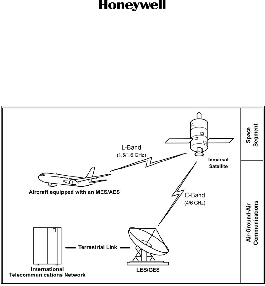
1. Inmarsat System Overview
This section provides an overview of the Inmarsat satellite communications system and networks.
Satellite communication systems provide users with long-range voice and data communication by
accessing global satellite and ground communications networks. Satellite communication systems
include global satellite networks, Land Earth Stations (LES), Ground Earth Stations (GES), Aircraft Earth
Stations (AES), and Mobile Earth Stations (MES).
The LES/GES is the part of the satellite communication system that is on the ground. These numerous,
international stations are responsible for routing voice and data calls from the MES/AES to their
destinations around the world. The MES/AES is the part of the satellite communication system that is on
the aircraft. GES and AES are the terms associated with Aero-H+ services. LES and MES are the terms
associated with other satellite communication services.
Inmarsat is an international organization that operates and maintains multiple geostationary satellites and
satellite networks (I-3 and I-4). For more information about I-3 and I-4 satellite beam coverage, refer to
the Inmarsat website—www.inmarsat.com.
I-3 satellites provide Inmarsat services for aviation (Aero H+ and Swift 64), shipping, and land-mobile
users. The satellites connect to ground telecommunication systems through a network of GESs. Each I-3
satellite is located over an Ocean Region (OR)—the current OR names are:
• Atlantic Ocean Region-East (AOR-E)
• Atlantic Ocean Region-West (AOR-W)
• Indian Ocean Region (IOR)
• Pacific Ocean Region (POR).
I-4 satellites provide worldwide SwiftBroadband (SBB service). Each I-4 satellite has 19 wide spot beams,
228 narrow spot beams, and is capable of accommodating many separate, simultaneous SBB sessions.
The SBB service and I-4 satellites support broadband applications. The current I-4 satellites are:
• AMERICAS
• EMEA (Europe, Middle East, and Africa)
• APAC (Asia-Pacific).
DRAFT as of
4 Mar 2016
DRAFT
Page 1-2
17 Mar 2016
23-15-87
© Honeywell International Inc. Do not copy without express permission of Honeywell.
SYSTEM DESCRIPTION, INSTALLATION, AND MAINTENANCE MANUAL
ARINC 781-500 SDU and SCM
The satellite communication avionics (A781-500 system), in conjunction with an antenna subsystem, act
as an AES/MES. The combined system provides users with a data and voice communications link to the
satellite network and global telecommunications system.
Figure 1-1 illustrates a simplified satellite communications system.
2. Equipment Overview
The A781-500 system, in combination with the antenna sub-system, provides Aeronautical Mobile
Satellite Services (AMSS) by facilitating airborne satellite communications over the Inmarsat network,
including the following services:
• Classic Aero-H+—Provides ACARS packet data services at 600, 1,200, or 10,500 bps over the PRT
channel combination and half-rate circuit switched voice service over the C channel. FAX data ser-
vices are not available over Classic Aero-H+.
• SwiftBroadband (SBB)—Provides AMBE+2 voice (circuit-switched) and broadband packet switched
services. The equipment can achieve aggregate rates of 432 kbps, but data rates may vary with net-
work load and signal quality.
Figure 1-1. Simplified Aeronautical Satellite Communications System
DRAFT as of
4 Mar 2016
DRAFT
Page 1-3
17 Mar 2016
23-15-87
SYSTEM DESCRIPTION, INSTALLATION, AND MAINTENANCE MANUAL
ARINC 781-500 SDU and SCM
© Honeywell International Inc. Do not copy without express permission of Honeywell.
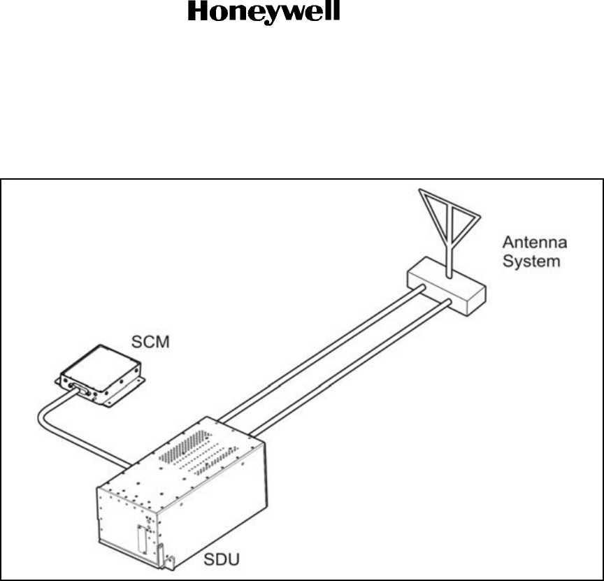
The A781-500 system consists of the Satellite Data Unit (SDU) and the Satellite Data Unit Configuration
Module (SCM).
Figure 1-2 illustrates the A781-500 system.
a2 Figure 1-2. A781-500 Avionics System
A. SDU
The SDU is the central communications processing and control unit and largely determines the
functionality of the complete SATCOM system. It manages interfaces, routing and priorities, and call
channel establishment and tear down. SDU provides RF power amplification using an internal high
power amplifier.
The SDU is divided into several shop replaceable units that are electrically connected via the
backplane. Various SRUs are also connected using RF cables.
B. SCM
The SCM is an external peripheral of the SDU and provides a dedicated interface to the SDU. It
stores Secure and User ORTs. The SCM can accommodate up to four Universal Subscriber Identity
Modules (USIM) that store subscriber information for the SBB network.
By storing configuration information independent of the SDU, the SCM facilitates efficient SDU
replacement. A new SDU that replaces a faulty SDU does not require any configuration. All
configuration information is obtained from the SCM.
DRAFT as of
4 Mar 2016

DRAFT
Page 1-4
17 Mar 2016
23-15-87
© Honeywell International Inc. Do not copy without express permission of Honeywell.
SYSTEM DESCRIPTION, INSTALLATION, AND MAINTENANCE MANUAL
ARINC 781-500 SDU and SCM
The terms Secure ORT and User ORT are consistent with the industry terminology as defined in
the ARINC 781-4 Characteristic. For the Boeing aircraft, the following terms are used:
- Options Selection Software (OSS) = Secure ORT
- Airline Modifiable Information (AMI) = User ORT.
3. Equipment Specifications
This section includes the physical and environmental characteristics of the A781-500 SDU and SCM.
Table 1-1 provides a summary of the physical characteristics and equipment specifications of the SDU
component.
Table 1-1. SDU Physical Characteristics and Specifications
CHARACTERISTIC SPECIFICATION
RELATED DOCUMENTS
ARINC characteristics ARINC 781-4 Mark 3 Aviation Satellite Communications
System
ARINC 600 Air Transport Avionics Equipment Interfaces
RTCA documents DO-178B, Software Considerations in Airborne Systems
and Equipment Certification
DO-160E, Environmental Conditions and Test
Procedures for Airborne Equipment
SDU SPECIFICATIONS
Physical size
Length 14.46 inches (36.73 cm)
Width 7.68 inches (19.51 cm)
Height 7.71 inches (19.58 cm)
Weight 24.9 pounds (11.30 kg)
Heating and cooling
Cooling air ARINC 600
Flow rate 28.16 oz//hr 104°F (50 kg/hr 40°C) (max) air
Pressure drop 0.2 ± 0.12 inH2O ( 5 ± 3 mmH2O)
Mounting information 6 MCU tray as per ARINC 600
Electrical interfaces
Power/control interface as per ARINC 781
Power requirements
Input voltage (AC) 100 VRMS to 122 VRMS AC, 300 to 900 Hz
Power consumption 400 VA
DRAFT as of
4 Mar 2016

DRAFT
Page 1-5
17 Mar 2016
23-15-87
SYSTEM DESCRIPTION, INSTALLATION, AND MAINTENANCE MANUAL
ARINC 781-500 SDU and SCM
© Honeywell International Inc. Do not copy without express permission of Honeywell.
Table 1-2 provides a summary of the physical characteristics and equipment specifications of the SCM
component.
Table 1-3 lists the RTCA/DO-160E environmental characteristics of the SDU and SCM.
Table 1-2. SCM Physical Characteristics and Specifications
Characteristic Specification
Related Documents
ARINC characteristics ARINC 781 Mark 3 Aviation Satellite Communications
System
RTCA documents DO-160E, Environmental Conditions and Test
Procedures for Airborne Equipment
SCM Specifications
Physical size
Length 4.7 inches (11.94 cm)
Width 4.0 inches (10.16 cm)
Height 1.0 inch (2.54 cm)
Weight 1.0 pound (0.454 kg)
Mounting information 4 x 0.125" holes on 3.3" x 3.5" spacing, per attachment
1-6 of ARINC 781
Electrical interfaces
Power/control interface as per ARINC 781
Power requirements Powered by SDU
Table 1-3. ARINC 781-500 SDU and SCM ERTCA/DO-160E Environmental Characteristics
Section Environmental Condition Category
4.0 Temperature and Altitude A2
4.5.1 Ground Survival Low A2
4.5.2 Operating Low Ambient A2
4.5.3 Short Time Operating High A2
4.5.4 Operating High Ambient A2
4.5.5 In Flight Loss of Cooling A2
Ground Survival Low Temperature A2
Ground Survival High Temperature A2
4.6.1 Altitude A2
5 Temperature Variation B
6 Humidity A
7 Operational Shock and Crash Safety B
8.5.2 Vibration Standard – Random S, Curve B
DRAFT as of
4 Mar 2016

DRAFT
Page 1-6
17 Mar 2016
23-15-87
© Honeywell International Inc. Do not copy without express permission of Honeywell.
SYSTEM DESCRIPTION, INSTALLATION, AND MAINTENANCE MANUAL
ARINC 781-500 SDU and SCM
9.0 Explosive Atmosphere E
15 Magnetic Effect A
16.5.1.4 Power Input (AC) Interruptions A(WF)H
17 Voltage Spike A
18 Audio Frequency Conducted Susceptibility (AC) K
19 Induced Signal Susceptibility CWX
20 Radio Frequency Susceptibility RR
21 Emission of RF Energy M
22 Lightning Induced Transient Susceptibility ZZZZZ
24 Icing X
25 Electrostatic Discharge (ESD) A
Table 1-3. ARINC 781-500 SDU and SCM ERTCA/DO-160E Environmental Characteristics
Section Environmental Condition Category
DRAFT as of
4 Mar 2016
DRAFT
Page 1-7
17 Mar 2016
23-15-87
SYSTEM DESCRIPTION, INSTALLATION, AND MAINTENANCE MANUAL
ARINC 781-500 SDU and SCM
© Honeywell International Inc. Do not copy without express permission of Honeywell.
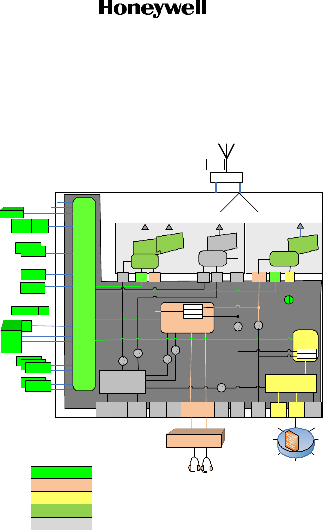
4. System Interfaces
This section describes the A781-500 system interfaces.
Figure 1-3 illustrates the block diagram of the A781-500 avionics system.
Figure 1-3. A781-500 Avionics System Block Diagram
NOTE: On the aircraft, only the Ethernet3 and 4-wire ports are supported.
A. SDU
The SDU is divided into the following LRUs:
• Channel cards (2)
Cha nnel Card 2
(DABC)
Cha nnel Card 1
(Sing le BGAN )
C hann el C ard
Pr oces sor 1
Clas sic
C han nel 1
P,R &T
Cha nnel Card
Proc esso r 2 A
ISDN TE
ISDN TE
ISDN TE
Data
Proce ssor
(DP)
ISDN
2
Ethernet
Spare
10 BT
FXS
(POTS )
FXS
(POT S )
CEPT -
E1
Classic
4-W ir e
1
Et h 3
QU AD
10 /100
Eth 1
TP
10BT
ISDN
1
Et h 4
QU AD
10/1 00
R1
R7
R2
R3
R4
ISDN Eth
ISDN
Voice Processor
(VP)
R6
Eth
SBB
4-Wire
2
SBB
SBB
C hann el C ard
Processor 2 B
Front
Pane l
10BT
Ser. Ser.
R8
R5
MCDU #3
MCDU #2
MCDU #1
CMU #2
D
781A
Ant, IF
DLNA
HPA
ISDN
MD
Et h ernet Sw it ch 2
(ESW 2)
Et hern et
Switch 1
(ESW 1)
NIM
Eth
Et h 2
TP
10 BT
C ontrol
Pr oc ess o r
TMS320
615
Data
Loader
Ser .
CMU #1
Audio Subsystem
Config
Straps
Read
Cct
CFDS
IRS #2
IRS #1
AES ID
DWO W
SCM
RF TxRF Rx
ISDN TE
ISDN TE
Le ge nd
Control Pr ocessor Domain
Voice Processor D omain
Data Pr ocessor Domain
C hannel C ards
Inactive/D isabled Items
DRAFT as of
4 Mar 2016

DRAFT
Page 1-8
17 Mar 2016
23-15-87
© Honeywell International Inc. Do not copy without express permission of Honeywell.
SYSTEM DESCRIPTION, INSTALLATION, AND MAINTENANCE MANUAL
ARINC 781-500 SDU and SCM
• Control and data processor card
• Voice processor card
• High power amplifier
• ARINC backplane
• DIN backplane
• 10 MHz oven controlled crystal oscillator
• Power supply.
The major interfaces of the SDU are listed in Table 1-4.
B. SCM
The SCM does not provide any interfaces other than a dedicated interface to the SDU.
The SCM is powered by the SDU.
5. User Interfaces
This section describes the A781-500 SDU interfaces that enable users to access Inmarsat services and
monitor the operation of the A781-500 system.
NOTE: There are no user interfaces associated with the SCM.
Table 1-4. SDU System Interfaces
System Interface Description
ACU/BSU (x1) Antenna control unit/beam steering unit
TCP (x3) Tuning and control panel. Interconnected to the SDU
multi-purpose control and display port
ACARS CMU (x2) Aircraft communication addressing and reporting system
communication management unit
IRS (x2)/GPS (x1) Inertial reference system/global positioning system
SCM (x1) SDU configuration module
AES ID (x1) Aircraft Earth station identification
Servicing DE-9 front panel
Button Test Button front panel
RF Transmit/receive to the DLNA
Antenna subsystem ARINC 781 antenna subsystem
Miscellaneous ARINC discrete input, outputs, and configuration straps
DRAFT as of
4 Mar 2016

DRAFT
Page 1-9
17 Mar 2016
23-15-87
SYSTEM DESCRIPTION, INSTALLATION, AND MAINTENANCE MANUAL
ARINC 781-500 SDU and SCM
© Honeywell International Inc. Do not copy without express permission of Honeywell.
A. TCP
The TCP is a device that uses an ARINC 429 interface per ARINC 739, which lets you communicate
with individual instruments on an aircraft, including the flight management system, very high
frequency radio, and the SDU.
B. 4-Wire Audio
The SDU supports two 4-wire audio interfaces.
C. Ethernet
The SDU supports two Ethernet data interfaces.
D. Maintenance Port
The SDU is equipped with a maintenance port, located on its front panel. The maintenance port
provides the physical connection to a password-protected Maintenance Port Utility (MPU) that
provides a system interface for users or service personnel who need to monitor or troubleshoot the
system.
For more information on configuring the maintenance port, refer to "Connecting to the MPU" on
page 4-2.
E. LEDs
The front panel of the SDU has two LEDs to indicate unit status:
• One green LED labeled Power
• One red LED labeled Fault.
Table 1-5 provides information about the LED signals.
F. Self-Test Button
The front panel of the SDU has a recessed button labelled Test.
NOTE: The Test button is recessed behind a red protective cap. To press the button, use a small
and thin tool with no sharp edges. You will not be able to press the button in far enough with
just your finger.
Table 1-5. SDU LED Status
Power LED Status Fault LED Status Description of SDU Status
LED is on LED is off No fault detected
LED is on LED is steadily on as long as
the fault exists
LRU fault detected
LED is on Flashing at 1 Hz with a 50%
duty cycle while the fault
exists
System fault detected but not isolated
to the LRU
Alternating flashing of Power and Fault LEDs Self-test in progress
DRAFT as of
4 Mar 2016

DRAFT
Page 1-10
17 Mar 2016
23-15-87
© Honeywell International Inc. Do not copy without express permission of Honeywell.
SYSTEM DESCRIPTION, INSTALLATION, AND MAINTENANCE MANUAL
ARINC 781-500 SDU and SCM
• To reset the unit, press and hold the Test button for at least 5 seconds.
• To initiate self-test (when no LEDs are flashing), momentarily press the Test button.
• When the self test completes (power on or user initiated) the Power LED will illuminate steady
for a period of 60 seconds and then it will deactivate for the duration of operation.
NOTE: During initial power-up or self-test execution, a momentary press of the self-test
button is ignored.
The LEDs indicate the results of the self-test. Table 1-5 provides information about the meaning of
LED signals.
6. Software Description
All operating software meets RTCA/DO-178B Level D requirements.
The SCM does not contain any software. Only configuration parameters are stored in the SCM.
The SDU software is not partitioned. The software is modular and modules run on individual Software
Logical Units (SLUs) within the SDU:
• Each channel card has a single SLU.
• Control and Data Processor card has a Control SLU and a Data SLU.
• Voice card has a Voice SLU.
DRAFT as of
4 Mar 2016

DRAFT
Page 2-1
17 Mar 2016
23-15-87
SYSTEM DESCRIPTION, INSTALLATION, AND MAINTENANCE MANUAL
ARINC 781-500 SDU and SCM
© Honeywell International Inc. Do not copy without express permission of Honeywell.
SYSTEM OPERATION
The SDU is an integral component in an AES. Together with the SCM, DLNA, Antenna, and HGA subsystem, it
provides AMSS by facilitating airborne satellite communication services over the Inmarsat network. These
services comprise Classic Aero-H+ and SwiftBroadband (SBB).
The SCM is a dedicated peripheral of the SDU and stores aircraft specific installation configuration critical to the
operation of the AES.
This section provides basic information on using the A781-500 system.
1. Registering and Activating Terminals
Registering and activating the A781-500 system has the following steps:
• Obtaining System Addresses
• Choosing Service Providers
• Registering Terminals.
A. Obtaining System Addresses
ICAO: Obtain your ICAO address from your local aeronautical authority. Your service provider will
require this address when you register for Classic Aero service.
USIM: Obtain SIM card(s) from your service provider. Your service provider will also activate these
cards to enable SBB service. One SIM card is required per channel of SBB service.
B. Choosing Service Providers
Contact Inmarsat for an up-to-date list of Inmarsat Service Providers using the following contact
information:
Inmarsat
99 City Road, London
EC1Y 1AX
Tel: +44 20 7728 1000
Fax: +44 20 728 1044
Customer Care
Tel: +44 20 7728 1777
Fax: +44 20 7728 1142
Email: customer_care@inmarsat.com
Web address: www.inmarsat.com
C. Registering Terminals
Contact your Inmarsat service provider and ask for a registration for service activation of Aircraft
Earth Station form. With this form, you can register for SBB, and Aero H+ services. The services
available depend on your service provider.
To complete the registration form you need the following information:
DRAFT as of
4 Mar 2016

DRAFT
Page 2-2
17 Mar 2016
23-15-87
© Honeywell International Inc. Do not copy without express permission of Honeywell.
SYSTEM DESCRIPTION, INSTALLATION, AND MAINTENANCE MANUAL
ARINC 781-500 SDU and SCM
• Customer information (address and contact information)
• Service provider details (obtained from your ISP)
• System and terminal information (terminal type, manufacturer, model number, serial number of
terminal)
• ICAO 24 bit technical address for Aero H+ services
• Aircraft information (tail number, fuselage/airframe number, manufacturer and model, and
country of registration)
• List of services required (for example, Aero H+ data-2, SBB PS, and SBB CS services)
• IMEI and IMSI for SBB services, printed on splash screen during boot-up while connected to
the maintenance port.
NOTE: IMSI is also printed on the SCM label.
NOTE: IMEIs are printed differently on the front panel maintenance port splash screen from
the SATCOM SWIFT CONFIG page on the TCP. The 14 digit IMEI appears in both
places. However, on the SATCOM SWIFT CONFIG page on the TCP, it has a 15th
digit appended to it. This digit is a check bit to validate the IMEI number.
2. Using the A781-500 System
This section describes how to perform the following tasks:
• Operating the TCP
• Logging On and Off
• Accepting and Making Calls in the Cockpit
• Accepting and Making Calls in the Cockpit
• Viewing BITE Information.
A. Operating the TCP
This section provides information about the TCP and its interfaces—output and input ports, the
screen, and the keyboard.screen and the keyboard.
(1) Screen
The TCP displays all data on the screen, as shown in Figure 2-1.
DRAFT as of
4 Mar 2016
DRAFT
Page 2-3
17 Mar 2016
23-15-87
SYSTEM DESCRIPTION, INSTALLATION, AND MAINTENANCE MANUAL
ARINC 781-500 SDU and SCM
© Honeywell International Inc. Do not copy without express permission of Honeywell.
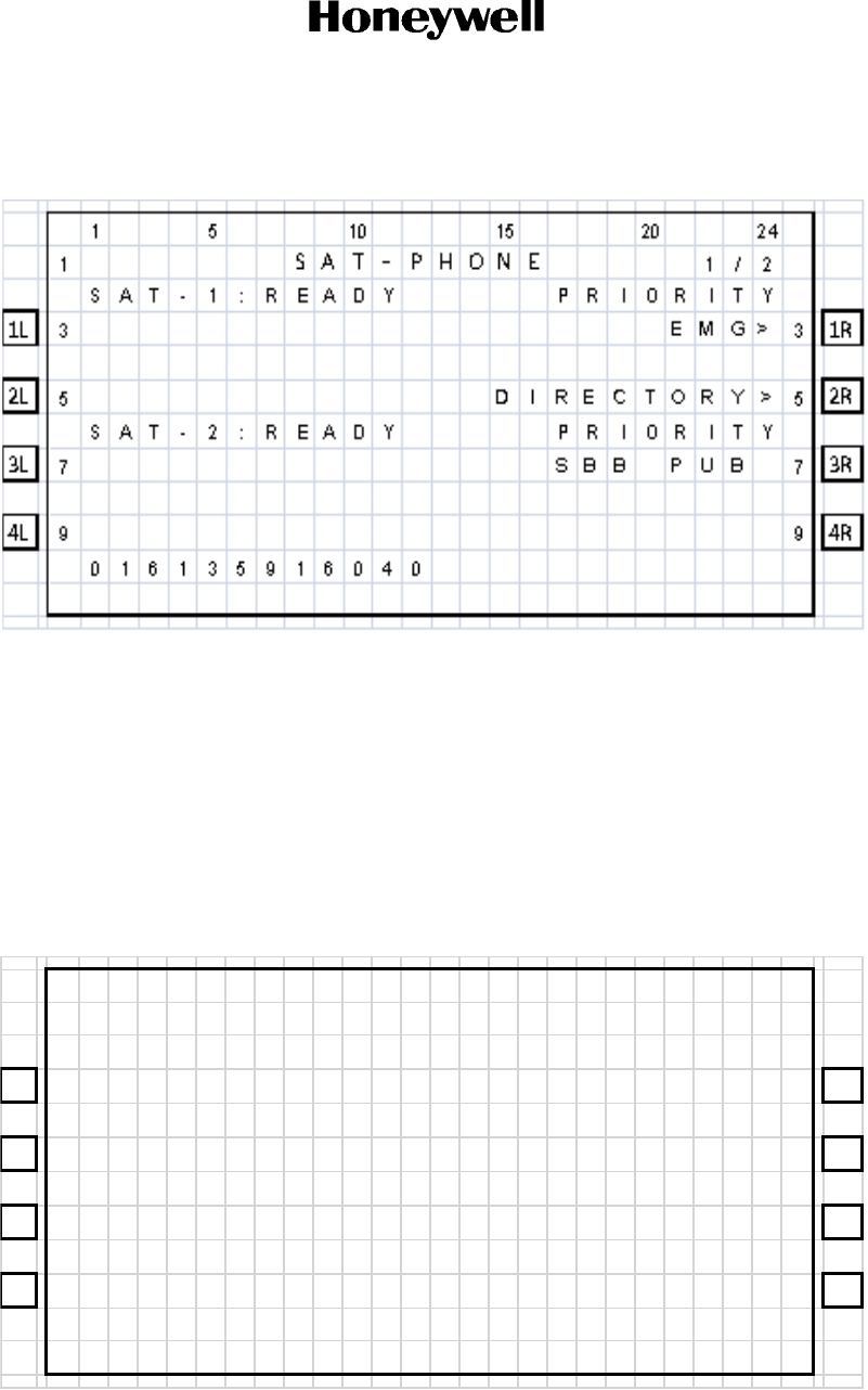
Figure 2-1. TCP Screen
NOTE: The SAT PHONE 1/2 menu shown in Figure 2-1 is an example where classic (SAT-1) and
SBB (SAT-2) cockpit calls are supported. Depending on the secure ORT parameter
settings, the prompts “SAT-1” and “SAT-2” can be replaced to display any message limited
to five characters.
The top of the screen displays the title of the menu on the screen. The bottom of the screen
(Line 14) is the scratchpad that displays information that you enter on the keyboard.
The TCP has four buttons on each side of the screen that activate TCP functions. Figure 2-1
displays these buttons on the left and right sides of the screen. When the functions
corresponding to a button are available, the function is displayed beside the button.
Other lines on the TCP screen display information relevant to the function or status of the
A781-500 system.
When a button has an action associated, there will be either a < or > symbol beside it.
(2) Keyboard
The TCP’s keyboard includes a set of numeric keys and a set of alphabetic keys, both of
which you can use to enter data into the TCP.
The keyboard may include preset keys, such as the following:
•The IDX or MAIN MENU key: this key returns you to the TCP’s main menu.
•The CLR key: this key clears any text you type into the scratchpad.
•The NEXT PAGE key: this key brings up the next page of a menu if one is available.
•The PREV PAGE key: this key brings up the previous page of a menu if one is available.
DRAFT as of
4 Mar 2016
DRAFT
Page 2-4
17 Mar 2016
23-15-87
© Honeywell International Inc. Do not copy without express permission of Honeywell.
SYSTEM DESCRIPTION, INSTALLATION, AND MAINTENANCE MANUAL
ARINC 781-500 SDU and SCM
(3) Special Symbols
Because of space constraints on the screen, the TCP uses a number of special symbols to
indicate actions:
•< or > appears when there is an action associated with that key.
•NUMBER/NUMBER appears to tell you which page out of how many pages you are
viewing. For example, 1/3 would appear when you are on page 1 of 3 pages in total.
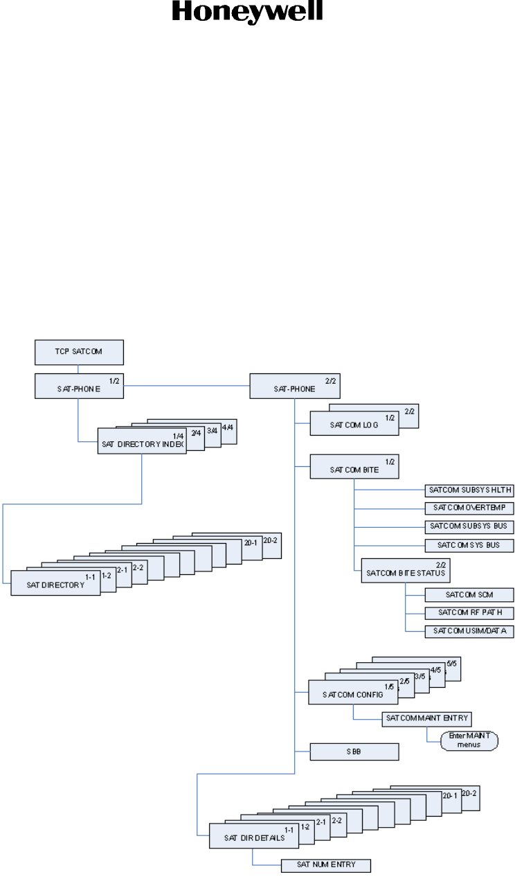
(4) Navigating the TCP
The TCP includes a number of menus, as shown in Figure 2-2.
Figure 2-2. A781-500 TCP Menu Structure
DRAFT as of
4 Mar 2016
DRAFT
Page 2-5
17 Mar 2016
23-15-87
SYSTEM DESCRIPTION, INSTALLATION, AND MAINTENANCE MANUAL
ARINC 781-500 SDU and SCM
© Honeywell International Inc. Do not copy without express permission of Honeywell.
B. Logging On and Off
Using the TCP, you can log on to the satellite network manually or automatically:
• Manual Logon—constrains the logon to use a satellite that you select
• Automatic Logon—logs on using the best available satellite as defined by the ORT.
If specified in the ORT, the initial system logon happens immediately after the
A781-500 system powers up, with no TCP input required. If the ORT is not configured as such, you
must initiate the logon from the TCP (MANUAL LOG-ON or AUTO LOG-ON command). For more
information, see "ORT Overview" on page 3-7.
You can watch the progress of the logon on the SATCOM LOG 1/2 menu, or simply wait until the
prompt on the SAT-PHONE 2/2 menu indicates the service is available for use.
(1) Logging On Automatically
When you initiate an automatic logon, the system selects a satellite and GES based on the
preferences specified in the ORT.
To log on automatically:
(a) On the SAT-PHONE 2/2 menu, press the button next to LOG.
The SATCOM LOG menu appears.
(b) On the SATCOM LOG menu, press the button next to AUTO LOG-ON.
If you return to the SAT-PHONE 1/2 menu, then the SAT-L and SAT-R channels are
updated with READY status after the logon completes.
NOTE: The TCP does not display the AUTO LOG-ON and MANUAL LOG-ON functions
when the A781-500 system is already logged on.
DRAFT as of
4 Mar 2016

DRAFT
SYSTEM DESCRIPTION, INSTALLATION, AND MAINTENANCE MANUAL
ARINC 781-500 SDU and SCM
Page 2-6
17 Mar 2016
23-15-87
© Honeywell International Inc. Do not copy without express permission of Honeywell.
NOTE: On the SAT-PHONE 2/2 menu, SAT-L shows the Classic Aero channel status
and SAT-R shows the SBB channel status. The A781-500 system logs on the
Classic Aero channels first, and then logs on the SBB channels.
(2) Logging On Manually
To log on manually, you must select a satellite and GES.
To log on manually:
(a) On the SAT-PHONE 2/2 menu, press the button next to LOG.
The SATCOM LOG menu appears.
(b) Press the button next to SATELLITE ID until the TCP screen shows the satellite ID to
which you want the A781-500 system to log on.
(c) Press the button next to GES ID until the TCP screen shows the GES to which you want
the A781-500 system to log on.
(d) On the SATCOM LOG menu, press the button next to MANUAL LOG-ON.
The TCP returns to the SAT-PHONE 2/2 menu and updates the SAT-L and SAT-R
channels with READY status after the log on completes.
NOTE: SAT-L shows the Classic Aero channel status and SAT-R shows the SBB channel
status. The A781-500 system logs on the Classic Aero channels first, and then
searches for SBB services on the satellite determined by the Classic Aero log-on.
(3) Logging Off Classic Aero Services
WARNING: THIS OPTION DOES NOT LOG OFF SBB OR SWIFT 64 SERVICES. IF EITHER
OF THESE SERVICES IS RUNNING, THEY WILL CONTINUE TO RUN AND
POTENTIAL CHARGES COULD BE MADE TO THE CABIN. TO COMPLETELY
LOG OFF, POWER DOWN THE A781-500 SYSTEM.
To log off:
(a) On the SAT-PHONE 2/2 menu, press the button next to LOG.
The SATCOM LOG menu appears.
(b) On the SATCOM LOG menu, press the button next to LOG-OFF.
The A781-500 system logs off the satellite network.
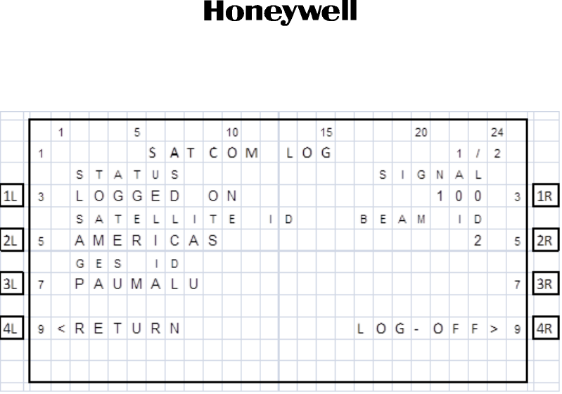
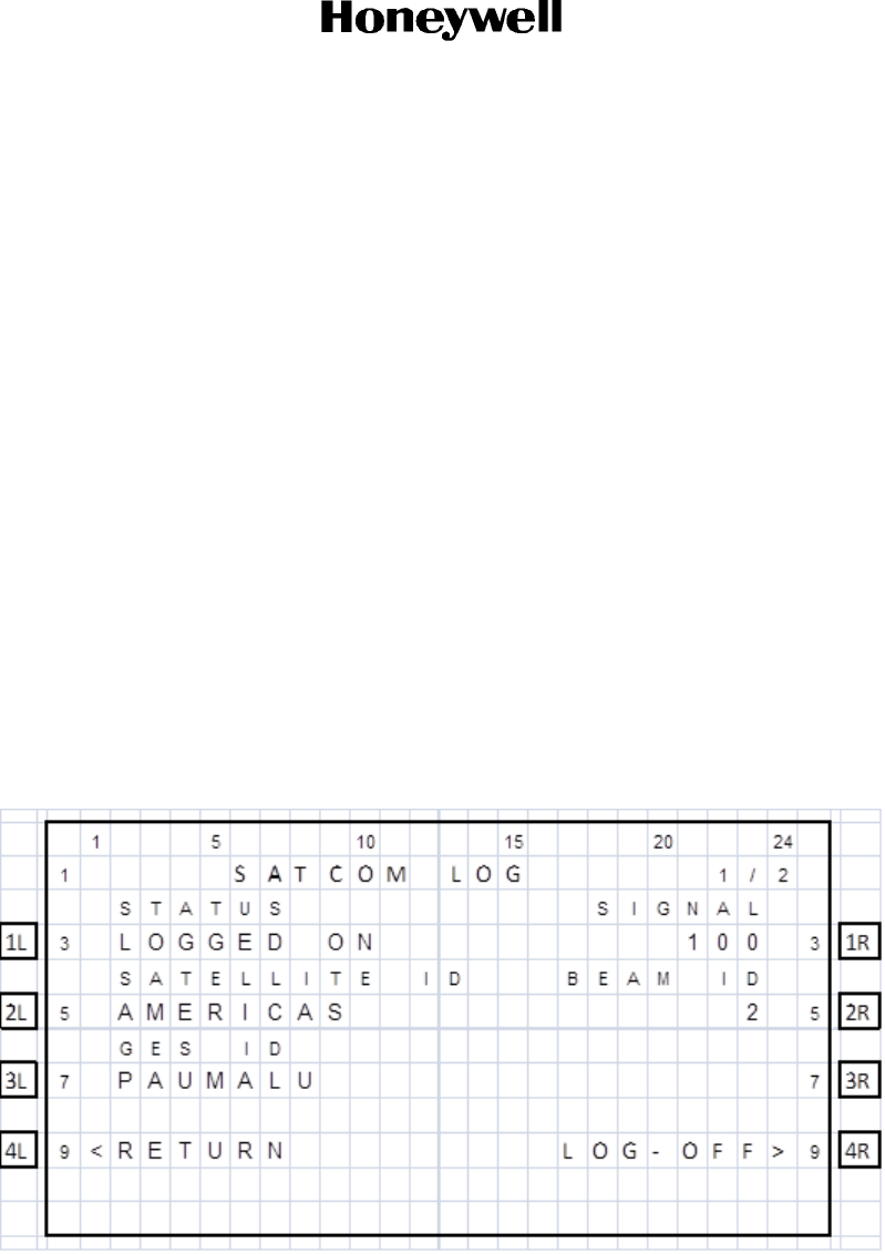
(4) Viewing Log Status
The log status defines whether the A781-500 system is logged on or logged off. Valid values
are shown in Table 2-1.
DRAFT as of
4 Mar 2016

DRAFT
Page 2-7
17 Mar 2016
23-15-87
SYSTEM DESCRIPTION, INSTALLATION, AND MAINTENANCE MANUAL
ARINC 781-500 SDU and SCM
© Honeywell International Inc. Do not copy without express permission of Honeywell.
To view log status:
(a) On the SAT-PHONE 1/2 menu, press the button next to LOG.
The SATCOM LOG menu appears.
(b) The log status appears on the line below STATUS.
C. Accepting and Making Calls in the Cockpit
You can make air-to-ground and air-to-air calls using the ARINC 781 system, the TCP, and one or
two four-wire headsets. You can manually dial calls or dial previously saved telephone numbers
from the TCP’s telephone directory.You can make air-to-ground and accept ground-to-air voice
calls using the A781-500 system, the TCP, the Audio Control Panel (ACP), and a four-wire cockpit
headset.
The four-wire cockpit headset supports Push to Talk (PTT) mode. Push to Talk mode mimics the
way an HF radio functions. The user's voice is only transmitted when the 'Mic On' input is asserted
i.e. grounded.
Table 2-1. A781-500 System Log Status
Log Status Description
SAFE MODE Configuration error detected
HSR NOT READY High stability oscillator is in a warming condition
AES ID NOT READY Displayed until a non-zero ICAO address is present
NAV DATA UNAVAIL Insufficient navigation data available
CC NOT READY Channel card has not fully booted
LOGGED OFF A781-500 system not logged on to the satellite network.
Awaiting input from the user
TUNING TO SAT Tuning and scanning for reception from the selected
satellite
DET SYS TABLE Updating the Satellite table
SPOT BEAM SEARCH Selecting the optimal spot beam
WAIT LOGON CONF Awaiting the logon confirmation from the satellite
WAIT LOGON ACK Awaiting for logon acknowledge from the GES
LOGGED ON Successfully logged on to GES
REJECT-TEMPORARY Logon rejected by the GES, but the condition is temporary
REJECT-PERMANENT Logon rejected by the GES, and the condition is
permanent
REJECT-INV PARAM Logon rejected by the GES due to invalid parameters, and
the condition is permanent
REJECT-AES INVAL ICAO address was not accepted by the GES, the
condition is permanent
LOGGING OFF Starting the logoff process
Note: For the 4 reject states, these statuses only stay on the display for 4 seconds.
DRAFT as of
4 Mar 2016

DRAFT
Page 2-8
17 Mar 2016
23-15-87
© Honeywell International Inc. Do not copy without express permission of Honeywell.
SYSTEM DESCRIPTION, INSTALLATION, AND MAINTENANCE MANUAL
ARINC 781-500 SDU and SCM
(1) Making Cockpit Calls
You can manually dial calls or dial previously saved telephone numbers from the TCP’s
telephone directory.
When the SDU cannot complete a call, the TCP displays CALL FAIL.The call and event logs
provide information about the cause of the call failure. Call and event logs are accessible to
avionics technicians through the maintenance port of the SDU.
(a) Making Calls from the Scratchpad
A call can only be initiated using the buttons on the TCP.
To make a call:
(1) Navigate to the SAT-PHONE 1/2 page.
(2) Enter a number in the TCP scratchpad using the following pattern.
00+CC+NNN+NUMBER (for calls within North America)
011+CC+NNN+NUMBER (for International calls)
where:
• 00 and 011 are access codes
• CC is the country code (Country Code may be up to 4 digits)
• NNN is the city or area code.
NOTE:
• You can enter up to 18 characters in the scratchpad (including hyphens), but the
maximum number of digits that can be dialed is 17.
• Hyphens are not necessary. If you wish to use hyphens, press the +/- key on the
scratchpad.
• To delete an incorrect character, press CLR on the scratchpad.
• To delete a number, press CLR on the TCP.
The number appears at the bottom of the TCP screen and MANUAL ENTRY
appears under the channel label.
DRAFT as of
4 Mar 2016
DRAFT
Page 2-9
17 Mar 2016
23-15-87
SYSTEM DESCRIPTION, INSTALLATION, AND MAINTENANCE MANUAL
ARINC 781-500 SDU and SCM
© Honeywell International Inc. Do not copy without express permission of Honeywell.
(3) Press the button next to MANUAL ENTRY.
NOTE: If an entry has MANUAL ENTRY under the SAT-1 label, that entry can be dialed
on Classic Aero channels. If an entry has MANUAL ENTRY under the SAT-2,
that entry can be dialed on SBB channels.
MAKE CALL and the number appear under the channel label.
1 5 10 15 20 24
1SAT ‐PHONE 1/2
SAT - 1 : READY PR IOR I TY
1L 3<MAKE CALL EMG> 31R
0016135916040
2L 5DIRECTORY>52R
PR I OR I TY
3L 7SBB PUB 73R
SAT - 2 : READY
4L 9<MANUAL ENTRY 94R
DRAFT as of
4 Mar 2016
DRAFT
Page 2-10
17 Mar 2016
23-15-87
© Honeywell International Inc. Do not copy without express permission of Honeywell.
SYSTEM DESCRIPTION, INSTALLATION, AND MAINTENANCE MANUAL
ARINC 781-500 SDU and SCM
(4) To set the priority, press the button next to PRIORITY.
Available priorities are as follows, all in order from highest to lowest.
• 1 EMERGENCY (EMG)—highest
• 2 OP-HIGH (HGH)
• 3 OP-LOW (LOW)
• 4 PUBLIC (PUB)—lowest.
NOTE: You can only set the priority for a Classic call. All calls made over SBB are
considered equal to public priority.
(5) On the TCP, press the button next to MAKE CALL.
The channel status displays DIALING, RINGING, and then ANSWERED when
connected.
(b) Making Calls from the Telephone Directory
You can make voice calls from the numbers you have saved in the TCP’s telephone
directory. Numbers can be saved in the telephone directory using the TCP or the ORT.
For more information on the ORT, see "ORT Overview" on page 3-7.
To make a call from the telephone directory:
(1) On the TCP main menu, press the button next to SAT.
(2) On the TCP keyboard, press the NEXT PAGE key to advance to the second page
of the SAT-PHONE menu, and then press the button next to DIRECTORY.
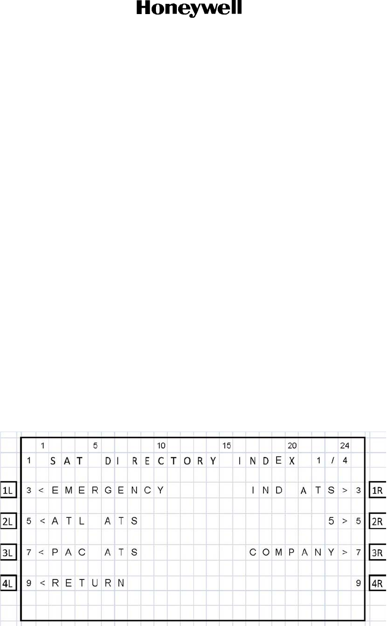
The SAT DIRECTORY INDEX menu appears.
DRAFT as of
4 Mar 2016
DRAFT
Page 2-11
17 Mar 2016
23-15-87
SYSTEM DESCRIPTION, INSTALLATION, AND MAINTENANCE MANUAL
ARINC 781-500 SDU and SCM
© Honeywell International Inc. Do not copy without express permission of Honeywell.
(3) To access phone numbers in a directory, press the key next to a directory name.
The SAT DIRECTORY page appears.
NOTE: If an entry has the < symbol in the SAT-L column, that entry can be dialed
on Classic Aero channels. If an entry has the > symbol in the SAT-R
column, that entry can be dialed on SBB channels. If there is no symbol,
the entry cannot be dialed on that channel.
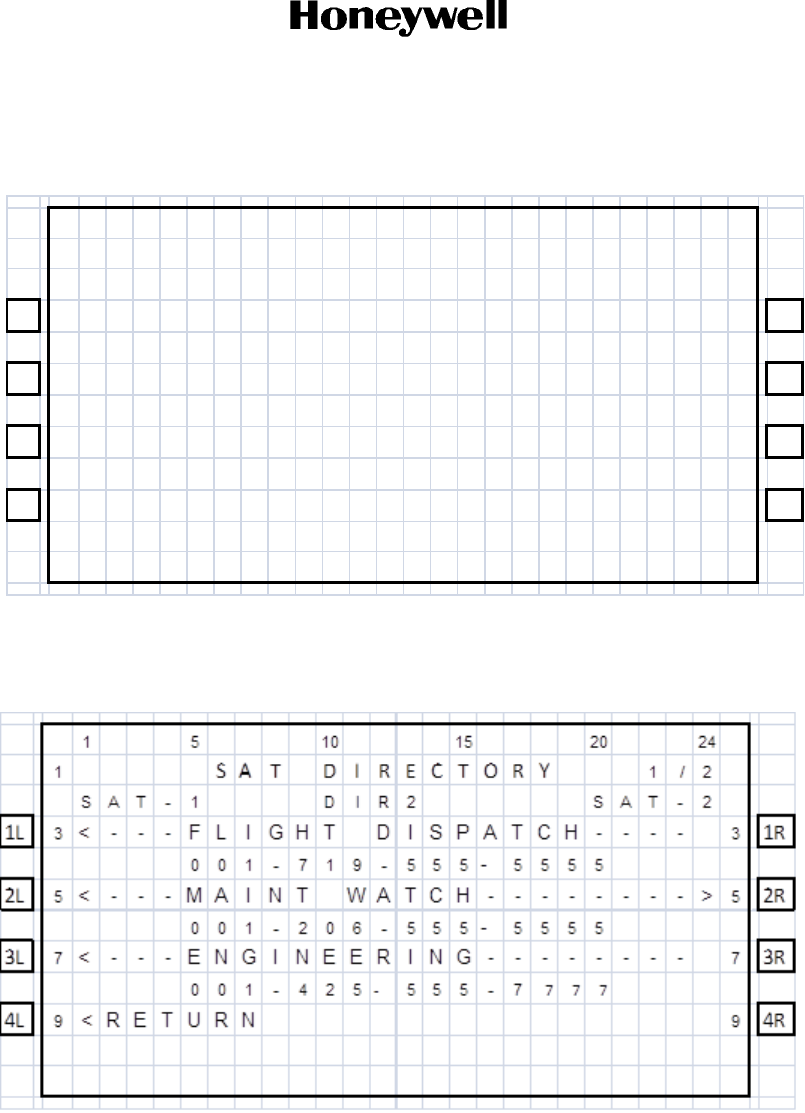
(4) Press the button to the left or right of the number you wish to dial.
• Pressing the left button loads the number on the Classic Aero channel.
• Pressing the right button loads the number on the SBB channel.
The TCP returns to page one of the SAT-PHONE menu and the number is
displayed under the selected channel.
(5) To set the priority, press the button next to PRIORITY.
NOTE: You can only set the priority for a Classic call. All calls made over SBB are
considered equal to public priority.
(6) Press the button next to MAKE CALL.
The channel status displays DIALING, RINGING, and then ANSWERED when
connected.
(c) Answering Calls
To answer a call:
• On the ACP, transition the MIC ON discrete from ON HOOK to OFF HOOK.
OR
1 5 10 15 20 24
1SA T D I R E C T OR Y 1 /2
SAT - 1 D IR2 SAT - 2
1L 3< ---FLIGHT DISPATCH---- 31R
001-719-555
‐5555
2L 5< ---MAINT WATCH-------->52R
001-206-555
‐5555
3L 7< ---ENGINEERING-------- 73R
001-425
‐555-7 777
4L 9<RETURN 94R
DRAFT as of
4 Mar 2016

DRAFT
Page 2-12
17 Mar 2016
23-15-87
© Honeywell International Inc. Do not copy without express permission of Honeywell.
SYSTEM DESCRIPTION, INSTALLATION, AND MAINTENANCE MANUAL
ARINC 781-500 SDU and SCM
On the TCP, press the button next to ANSWER to answer the call or press the button
next to REJECT to reject the call.
(d) Ending Calls
To end a call:
• On the TCP on the menu, press the button next to END CALL.
OR
On the ACP, assert the Place/End switch.
(2) Call Priority
The A781-500 system has four priority settings for calls:
• 1 EMERGENCY (EMG)—highest
• 2 OP-HIGH (HGH)
• 3 OP-LOW (LOW)
• 4 PUBLIC (PUB)—lowest.
(a) Setting the Call Priority
You can set the priority for an air-to-ground four-wire Classic call before making the call.
This priority setting allows for preemption of existing lower priority Aero H+ calls if
insufficient satellite resources exist to establish an independent call, and for preemption
of calls and services within the cabin.
If the four-wire Classic call is the same priority as an existing call, the established call
will be retained and the new call will be queued.
Cockpit calls over SBB are Public priority calls. You can not change the priority.
All calls made from the interfaces other than the cockpit four-wire phones or ACARS
CMU are Public priority calls.
(b) Receiving a Priority Call
If a cockpit call is in progress and a higher priority ground-to-air call is received, the
higher priority incoming call will preempt the existing call. The preemption is automatic,
and the caller in the cockpit has no option to choose between calls.
(3) Saving Telephone Numbers in the Telephone Directory
You can save telephone numbers to the TCP’s telephone directory to use later, and you can
dial telephone numbers from the telephone directory.
NOTE: Saving telephone numbers in the directory may be inhibited by ORT options.
To save telephone numbers to the telephone directory:
DRAFT as of
4 Mar 2016
DRAFT
Page 2-13
17 Mar 2016
23-15-87
SYSTEM DESCRIPTION, INSTALLATION, AND MAINTENANCE MANUAL
ARINC 781-500 SDU and SCM
© Honeywell International Inc. Do not copy without express permission of Honeywell.
(1) Navigate to the SAT-PHONE 2/2 menu and press the button next to DIR DETAILS.
The SAT DIR DETAILS menu appears and shows directory page 1. There are 20
phone directories with five phone number entries available in each directory.
Use NEXT PAGE and PREV PAGE to navigate to the directory in which you want
to add or modify a phone number entry.
1 5 10 15 20 24
1SAT ‐PHONE 2/2
1L 3<LOG B I TE FA I L>
31R
2L 5<D I R DETA I LS CONF I G> 52R
3L 7SBB> 73R
4L 9 9 4R
DRAFT as of
4 Mar 2016

DRAFT
Page 2-14
17 Mar 2016
23-15-87
© Honeywell International Inc. Do not copy without express permission of Honeywell.
SYSTEM DESCRIPTION, INSTALLATION, AND MAINTENANCE MANUAL
ARINC 781-500 SDU and SCM
(2) To modify an entry, press the button next to the entry. To add a new entry, press the
button next to an empty line.
(3) Type the name associated with the telephone number in the scratchpad and then
press the button next to the name field on the TCP screen.
• The maximum number of characters for a name is 14.
(4) Enter a number in the TCP scratchpad using the following pattern.
00+CC+NNN+NUMBER (for calls within North America)
011+CC+NNN+NUMBER (for International calls)
where:
• 00 and 011 are access codes
• CC is the country code (Country Code may be up to 4 digits)
• NNN is the city or area code
NOTE:
• You can enter up to 18 characters in the scratchpad (including hyphens), but the
maximum number of digits that can be dialed is 17.
• Hyphens are not necessary. If you wish to use hyphens, press the +/- key on the
scratchpad.
(5) Press the button next to the phone number field on the TCP screen.
(6) Press the button next to PRIORITY to select a priority for the phone number.
(7) To save the entry, press the button next to STORE. To cancel the new entry, press
the button next to CANCEL.
(8) Press the button next to CONFIRM.
The entry is saved.
NOTE: You can protect directory entries using the Phonebook ORT parameter. If
an entry is protected, it cannot be modified or deleted. For more
information about the Phonebook ORT parameter, refer to "ORT
Overview" on page 3-7.
D. Viewing BITE Information
From the SATCOM BITE menu, you can view BITE information to determine subsystem health.
To view BITE information:
(a) On the TCP main menu, press the button next to SAT.
(b) On the TCP keyboard, press the NEXT PAGE key to advance to the second page of the
SAT-PHONE menu, and then press the button next to SATCOM BITE.
The SATCOM BITE menu appears.
DRAFT as of
4 Mar 2016
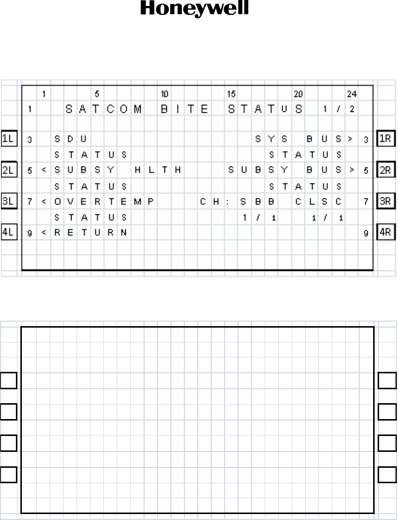
DRAFT
Page 2-15
17 Mar 2016
23-15-87
SYSTEM DESCRIPTION, INSTALLATION, AND MAINTENANCE MANUAL
ARINC 781-500 SDU and SCM
© Honeywell International Inc. Do not copy without express permission of Honeywell.
You can view the following information from this screen:
• SDU status on the line below SDU
• Overall health of all subsystem components (SCM, DLNA, and HGA) on the line below
SUBSY HLTH
• Thermal status of the SDU and HGA on the line below OVERTEMP
• SCM health on the line below SCM
• Peripheral LRU bus status on the line below SYS BUS
1 5 10 15 20 24
1 SATCOM B I TE STATUS2/2
1L 3<SCM RF PATH> 31R
OK OK
2L 5 US IM/DATA> 52R
1/1 1
/1
3L 7 73R
4L 9<RETURN 94R
DRAFT as of
4 Mar 2016
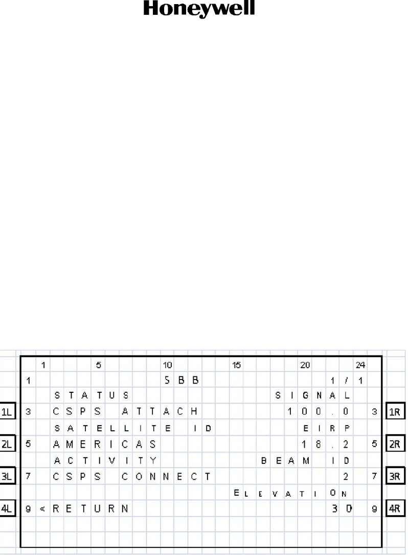
DRAFT
Page 2-16
17 Mar 2016
23-15-87
© Honeywell International Inc. Do not copy without express permission of Honeywell.
SYSTEM DESCRIPTION, INSTALLATION, AND MAINTENANCE MANUAL
ARINC 781-500 SDU and SCM
• Subsystem bus status on the line below SUBSY BUS
• The number of functional channels followed by the number of installed channels on the
line below CHANNELS
• The number of functioning SBB channels and Classic channels below CH-SBB CLSC
• RF path status on the line below RF PATH
• USIM and data bus status on the line below USIM/DATA.
NOTE: Valid values for status are OK and FAIL. If the status of a subsystem is FAIL, press
the button next to the subsystem to view the details.
To view more information about the health of a particular subsystem, press the button next to the
name of the subsystem. For more information about the various TCP menu screens, see
"Troubleshooting and Fault Isolation" on page 4-8.
3. Channel Status and System Configuration
A. SBB Status
As shown in Figure 2-3, the SBB menu provides information about the status of the SBB service.
Figure 2-3. SBB Menu
DRAFT as of
4 Mar 2016

DRAFT
Page 2-17
17 Mar 2016
23-15-87
SYSTEM DESCRIPTION, INSTALLATION, AND MAINTENANCE MANUAL
ARINC 781-500 SDU and SCM
© Honeywell International Inc. Do not copy without express permission of Honeywell.
Table 2-2 describes the information available in the SBB menu.
Table 2-2. SBB Menu
Label Description
Status The status of the SBB channel. Possible values are:
• HSR NOT READY—high stability oscillator is warming
• USIM WARMING—USIM is warming
• NOT READY—channel card has not yet started
registration, and may be waiting on the Classic card
• ATTACHING—satellite identified and attach has begun
• CS ATTACH—attach complete, circuit-switch granted
• PS ATTACH—attach complete, packet-switch granted
• CSPS ATTACH—attach complete, circuit-switch and
packet-switch granted
• ATTACH-FAIL— attach failed, with the 3GPP cause code
• NOT READY—selected satellite does not support SBB
• DISABLED—selected SBB service is not configured in the
operational mode
Satellite The selected ocean region.
Activity The activity status of the SBB service. Possible values are:
• CS CONNECT—Circuit Switched services in use
• PS CONNECT—Packet Switched services in use
• CSPS CONNECT—Circuit Switched services and Packet
Switched services in use
• NONE —No services in use
Signal The current signal quality.
EIRP The EIRP setting of the channel.
Beam ID The current beam ID for the service.
Elevation The computed elevation angle for the antenna pointing
vector.
DRAFT as of
4 Mar 2016
DRAFT
Page 2-18
17 Mar 2016
23-15-87
© Honeywell International Inc. Do not copy without express permission of Honeywell.
SYSTEM DESCRIPTION, INSTALLATION, AND MAINTENANCE MANUAL
ARINC 781-500 SDU and SCM
B. Channel Information and Bit Errors
As shown in Figure 2-4, the SATCOM LOG 2 menu provides information about the current channel
and the bit error rate.
Figure 2-4. SATCOM LOG 2 menu
Table 2-3 describes the information available in the SATCOM LOG 2 menu.
C. System Part Numbers
As shown in Figure 2-5, the SATCOM CONFIG 1 menu provides the hardware part numbers of the
SDU and the SCM.
Table 2-3. SATCOM LOG 2 Menu
Label Description
Channel # Channel number representation of the P channel, displayed
only when the SDU is logged on, otherwise the display is
blank.
Bit Errors The raw bit error rate.
ICAO The current ICAO address.
Doppler The doppler correction.
1 5 10 15 20 24
1SATCOMLOG 2/2
CHANNEL # DOPPL ER
1L 314008 -1999HZ 31R
B I T ERRORS
2L 5052R
ICAO
3L 701234567 73R
4L 9<RETURN 94R
DRAFT as of
4 Mar 2016
DRAFT
Page 2-19
17 Mar 2016
23-15-87
SYSTEM DESCRIPTION, INSTALLATION, AND MAINTENANCE MANUAL
ARINC 781-500 SDU and SCM
© Honeywell International Inc. Do not copy without express permission of Honeywell.
SFigure 2-5. SATCOM CONFIG 1 Menu
Table 2-4 describes the information available in the SATCOM CONFIG 1 menu.
Table 2-4. SATCOM CONFIG 1 Menu
Label Description
Hardware Part Number Part number of the A781-500 SDU.
Serial Number Serial number of the A781-500 SDU.
PROT Level Code This code is displayed if the SATCOM CONFIG menu is
accessed from the In-Flight menus. It allows access to the
Maintenance Mode TCP menus. Contact RC Product
Support for the PROT level code.
1 5 10 15 20 24
1 SATCOM CONFIG
1/5
HARDWARE PART NUMB ER
1L 3 822 -2556 -XXXXXX 31R
SERIAL NUMBER
2L 5 147206XXXXX 52R
3L 7 73R
PROT L EV EL CODE
4L 9<RETURN XXXX> 94R
DRAFT as of
4 Mar 2016
DRAFT
Page 2-20
17 Mar 2016
23-15-87
© Honeywell International Inc. Do not copy without express permission of Honeywell.
SYSTEM DESCRIPTION, INSTALLATION, AND MAINTENANCE MANUAL
ARINC 781-500 SDU and SCM
As shown in Figure 2-6, the SATCOM CONFIG 2 menu provides the software part numbers of the
equipment in the A781-500 system.
Figure 2-6. SATCOM CONFIG 2 Menu
Table 2-5 describes the information available in the SATCOM CONFIG 2 menu.
As shown in Figure 2-7, the SATCOM CONFIG 3 menu provides the software numbers of the
Secure ORT and the User ORT.
Table 2-5. SATCOM CONFIG 2 Menu
Label Description
Software Location ID TBD
SW Part Number SDU
OPS Software part number of the operational software in the
A781-500 SDU.
1 5 10 15 20 24
1 S AT COM CONF I G
2/5
SOFTWARE LOCAT ION ID
1L 3 LSXXXXXXX 31R
SW LOC ID DESCR I PT ION
2L 5 SATCOM 52R
SW PAR T NUMBER OPS
3L 7 COLCC -SSSS- SSSS 73R
4L 9<RETURN 94R
DRAFT as of
4 Mar 2016
DRAFT
Page 2-21
17 Mar 2016
23-15-87
SYSTEM DESCRIPTION, INSTALLATION, AND MAINTENANCE MANUAL
ARINC 781-500 SDU and SCM
© Honeywell International Inc. Do not copy without express permission of Honeywell.
Figure 2-7. SATCOM CONFIG 3 Menu
Table 2-6 describes the information available in the SATCOM CONFIG 3 menu.
As shown in Figure 2-8, the SATCOM CONFIG 4 menu provides the hardware part number and
serial number of the antenna in the A781-500 system.
Figure 2-8. SATCOM CONFIG 4 Menu
Table 2-6. SATCOM CONFIG 3 Menu
Label Description
SW Part Number OSS Software part number of the Secure ORT (OSS)
SW Part Number AMI Software part number of the User ORT (AMI)
1 5 10 15 20 24
1 S AT COM CONF I G
3/5
SW PART NUMB ER OSS
1L 3 COLCC -SSSS- SSSS 31R
SW PART NUMB ER AM I
2L 5 COLCC -SSSS- SSSS 52R
3L 7 7
3R
4L 9<RETURN 94R
1 5 10 15 20 24
1 SATCOM CONFIG
4/5
SATELLITE HGA
1L 3 HARDWARE PART N UMB ER 3 1R
xxxxxxxxxxxxxxxx
2L 5 SERIAL NUMBER 5 2R
xxxxxxxxxxxxx xxx
3L 7 73R
4L 9<RETURN 94R
DRAFT as of
4 Mar 2016
DRAFT
Page 2-22
17 Mar 2016
23-15-87
© Honeywell International Inc. Do not copy without express permission of Honeywell.
SYSTEM DESCRIPTION, INSTALLATION, AND MAINTENANCE MANUAL
ARINC 781-500 SDU and SCM
Table 2-7 describes the information available in the SATCOM CONFIG 4 menu.
As shown in Figure 2-9, the SATCOM CONFIG 5 menu provides the hardware part number and
serial number of the SCM.
Figure 2-9. SATCOM CONFIG 5 Menu
Table 2-8 describes the information available in the SATCOM CONFIG 5 menu.
Table 2-7. SATCOM CONFIG 4 Menu
Label Description
Hardware Part Number Hardware part number of the HGA
Serial Number Serial number of the HGA
Table 2-8. SATCOM CONFIG 5 Menu
Label Description
Hardware Part Number Hardware part number of the SCM
Serial Number Serial number of the SCM
1 5 10 15 20 24
1 SATCOM CONFIG
5/5
SDU CONF I G MODUL E
1L 3 HARDWARE PART N UMB ER 3 1R
P / N RECE I VED FROM SCM
2L 5 SERIAL NUMBER 5 2R
S / N RECE I VED FROM SCM
3L 7 73R
4L 9<RETURN 94R
DRAFT as of
4 Mar 2016
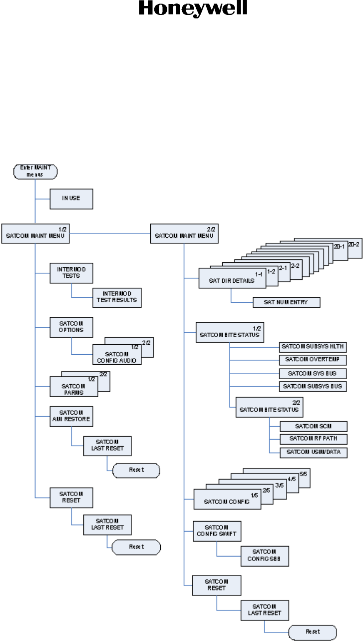
DRAFT
Page 2-23
17 Mar 2016
23-15-87
SYSTEM DESCRIPTION, INSTALLATION, AND MAINTENANCE MANUAL
ARINC 781-500 SDU and SCM
© Honeywell International Inc. Do not copy without express permission of Honeywell.
4. Maintenance Mode
The maintenance menus of the TCP provide the same configuration and BITE information available in
In-Flight mode, and provide access to the PIM test, audio configuration, and other options and
parameters.
Maintenance mode includes a number of TCP menus, as shown in Figure 2-10.
Figure 2-10. Maintenance Mode TCP Menu Structure
DRAFT as of
4 Mar 2016

DRAFT
Page 2-24
17 Mar 2016
23-15-87
© Honeywell International Inc. Do not copy without express permission of Honeywell.
SYSTEM DESCRIPTION, INSTALLATION, AND MAINTENANCE MANUAL
ARINC 781-500 SDU and SCM
A. Accessing Maintenance Mode
You can only access the TCP maintenance menus when the plane is on the ground and classic
services are logged off.
To access the maintenance menus:
1. In the SATCOM CONFIG 1/4 menu, type the protection level code in the scratchpad, and press
the button next PROT LEVEL CODE.
NOTE: Contact RC Product Support for the PROT level code.
The TCP displays the MAINTENANCE ENTRY page.
To enter Maintenance Mode, press the button next to CONFIRM.
The SATCOM MAINT MENU appears.
.
1 5 10 15 20 24
1MA I NTENANCE ENTRY
1L 3 THIS WILL REQUIRE 31R
SATCOM TO COLDSTART
2L 5UPON EX I TI NG MAI NT PAGES52R
NOTE : OTHER A CT I VE TCPS
3L 7CENTER TC P 73R
RI GH T T C P
4L 9<CANCEL CONF IRM
>94R
DRAFT as of
4 Mar 2016

DRAFT
Page 2-25
17 Mar 2016
23-15-87
SYSTEM DESCRIPTION, INSTALLATION, AND MAINTENANCE MANUAL
ARINC 781-500 SDU and SCM
© Honeywell International Inc. Do not copy without express permission of Honeywell.
B. Viewing BITE Information
The BITE information available in maintenance mode is the same as the BITE information available
in In-Flight mode. For information about the BITE menus, see "Viewing BITE Information" on page
2-14.
C. Starting the Intermod Test
For information and instructions about running the PIM test, see "PIM Test" on page 3-8.
D. Viewing Configuration
The configuration menus available in maintenance mode are the same as the configuration menus
in In-Flight mode. For information about these menus, see "System Part Numbers" on page 2-18.
E. Viewing SATCOM Parameters
As shown in Figure 2-11, the SATCOM PARMS menu provides information about logon, fallback,
and the channel cards.
1 5 10 15 20 24
1 SATCOM MA INT M
ENU 1/2
1L 3<INTERMOD TEST OPTIONS
>31R
2L 5PARMS>52R
3L 7AMI RESTORE>73R
4L 9 RESUME>94R
DRAFT as of
4 Mar 2016

DRAFT
Page 2-26
17 Mar 2016
23-15-87
© Honeywell International Inc. Do not copy without express permission of Honeywell.
SYSTEM DESCRIPTION, INSTALLATION, AND MAINTENANCE MANUAL
ARINC 781-500 SDU and SCM
Figure 2-11. SATCOM PARMS
1 5 10 15 20 24
1SATCOM PARMS 1/2
L OGON MODE SDU/ AN T
1L 3<AUTO 2.0 31R
DD / MM / YY
2L 523 / 07 /14 52R
TIME
3L 71354 73R
4L 9<RETURN 94R
1 5 10 15 20 24
1SATCOM PARMS 2/2
1L 3 1 CHAN CARD 31R
SBB*
2L 5 5 2R
2 CHAN CARD
3L 7CLSC VO I CE / DATA * 73R
4L 9<RETURN 94R
DRAFT as of
4 Mar 2016
DRAFT
Page 2-27
17 Mar 2016
23-15-87
SYSTEM DESCRIPTION, INSTALLATION, AND MAINTENANCE MANUAL
ARINC 781-500 SDU and SCM
© Honeywell International Inc. Do not copy without express permission of Honeywell.
Table 2-9 describes the information available in the SATCOM PARMS menu.
F. Viewing SATCOM Options
As shown in Figure 2-12, the SATCOM OPTIONS menu provides information about audio and
phone operation.
Figure 2-12. SATCOM OPTIONS
Table 2-10 describes the information available in the SATCOM OPTIONS menu.
Table 2-9. SATCOM PARMS Menu
Label Description
LOGON MODE AUTO or MANUAL
DD/MM/YY Current date
TIME Current time
SDU/ANT Estimated loss between the SDU and antenna
CHAN CARD1 SBB
CHAN CARD2 CLSCVOICE/DATA
Table 2-10. SATCOM OPTIONS Menu
Label Description
CHIME-A2G Value of the CHIME A2G ORT parameter.
CALLED PARTY Display mode selection for call placement.
MANUAL DIAL Current state of the scratchpad number entry control.
1 5 10 15 20 24
1SAT COM OP T I ONS
1L 3 3 1R
CH IME - A2G CALLED PARTY
2L 5ALWAYS NAME> 52R
MA N U A L D I A L
3L 7<CONF IG AUD IO ALWAYS>73R
4L 9<RETURN 94R
DRAFT as of
4 Mar 2016
DRAFT
Page 2-28
17 Mar 2016
23-15-87
© Honeywell International Inc. Do not copy without express permission of Honeywell.
SYSTEM DESCRIPTION, INSTALLATION, AND MAINTENANCE MANUAL
ARINC 781-500 SDU and SCM
G. Configuring Audio Options
As shown in Figure 2-13 and Figure 2-14, the SATCOM CONFIG AUDIO menu provides
information and settings for cockpit phone operation.
Figure 2-13. CONFIG AUDIO 1/2
Table 2-11 describes the information available in the SATCOM CONFIG AUDIO 1 menu.
Table 2-11. SATCOM CONFIG AUDIO 1 Menu
Label Description
AUDIO LINE Switch between four-wire 1 and four-wire 2.
SPEAKER Headset speaker level—0 to 100.
MICROPHONE Microphone level—0 to 100.
SIDETONE Sidetone level—0 to 100.
NOISE Headset speaker noise level—0 to 100.
1 5 10 15 20 24
1SATCOM CONFIG AUDI O 1/2
AUDI OLI NE
1L 3 4-WIRE 1>3 1R
2L 5 SPEAKER 100 52R
M I CROPH ONE 5 0
3L 7SI DETONE 5 0 73R
NO I SE 5 0
4L 9<RETURN 94R
DRAFT as of
4 Mar 2016
DRAFT
Page 2-29
17 Mar 2016
23-15-87
SYSTEM DESCRIPTION, INSTALLATION, AND MAINTENANCE MANUAL
ARINC 781-500 SDU and SCM
© Honeywell International Inc. Do not copy without express permission of Honeywell.
Figure 2-14. CONFIG AUDIO 2/2
Table 2-12 describes the information available in the SATCOM CONFIG AUDIO 2 menu.
Table 2-12. SATCOM CONFIG AUDIO 2 Menu
Label Description
AUDIO LINE Switch between four-wire 1 and four-wire 2.
PUBLIC CALLS Displays the value of the Ground Initiated Public Call Routing ORT parameter.
This parameter enables the placing and acceptance of public calls via the
analog audio lines.
TERMINAL ID The terminal ID for the selected audio line interface.
PRIORITY The priority of calls allowed via the selected audio interface. The possible values
are:
•COCKPIT
•PUBLIC
•ALL
1 5 10 15 20 24
1SATCOM CONFIG AUDI O 2/2
AUDI OLI NE
1L 3 4-WIRE 1>3 1R
PUBLIC CALLS PRIORITY
2L 5ENABLED ALL 52R
TERMINAL ID
3L 7173R
4L 9<RETURN 94R
DRAFT as of
4 Mar 2016

DRAFT
Page 2-30
17 Mar 2016
23-15-87
© Honeywell International Inc. Do not copy without express permission of Honeywell.
SYSTEM DESCRIPTION, INSTALLATION, AND MAINTENANCE MANUAL
ARINC 781-500 SDU and SCM
Blank Page
DRAFT as of
4 Mar 2016

DRAFT
Page 3-1
17 Mar 2016
23-15-87
SYSTEM DESCRIPTION, INSTALLATION, AND MAINTENANCE MANUAL
ARINC 781-500 SDU and SCM
© Honeywell International Inc. Do not copy without express permission of Honeywell.
INSTALLATION
This section describes the procedures required to install the A781-500 system (SDU and SCM) on an aircraft,
including the following sections:
• Advisories
• Pre-Installation Inspection
• Installation Procedure
• Connection Details
• Owners Requirements Table (ORT)
• Passive Intermodulation (PIM) Test
• Installation and Engineering Drawings
1. Advisories
Before performing any installation procedures, read the safety advisories listed in the Introduction on page
INTRO–4 of this manual.
2. Pre-Installation Inspection
Before installing any A781-500 system, conduct a pre-installation inspection of all parts to make sure that
no damage occurred during shipping.
A. Unpacking and Inspecting Equipment
• Unpack the A781-500 equipment from the shipping containers.
• Verify that the part number displayed on the shipping box and equipment component matches
the model and part number ordered. If components are missing from the shipment, contact the
supplier immediately and report the problem.
• Visually inspect the A781-500 equipment for any shipping damage. If any shipping damage has
occurred, contact the shipping carrier immediately and report the problem.
• Check the A781-500 equipment connectors for corrosion and damage. If damage is noted, do
not apply power to the equipment. Contact the supplier immediately to report the problem.
B. Cabling Notes
Before proceeding with the installation of the A781-500 system, read all cabling notes provided on
the Interconnection and Contact Assignment drawings.
3. Installation Procedure
Only authorized technical personnel, trained in general aviation workmanship, that have a basic
understanding of SATCOM systems should proceed with the following procedure.
Before performing any installation procedures, read the safety advisories listed in "Safety Advisories" on
page INTRO-4 of this manual.
CAUTION: THE A781-500 SYSTEM REQUIRES CONDITIONED AIR PER ARINC781.
DRAFT as of
4 Mar 2016

DRAFT
Page 3-2
17 Mar 2016
23-15-87
© Honeywell International Inc. Do not copy without express permission of Honeywell.
SYSTEM DESCRIPTION, INSTALLATION, AND MAINTENANCE MANUAL
ARINC 781-500 SDU and SCM
1. Install the SDU in a 6 MCU tray as per ARINC 600. The minimum clearance between the SDU and
any other equipment installed above it shall be no less than 0.5 inches (12.7 mm).
2. Install the SCM in any orientation. Refer to Table 1-2 on page 5 for the SCM mounting specification.
• There are no clearance requirements for the SCM.
3. Connect the SCM to the SDU. The SDU supports one RS-422 interface for interconnect to the SCM.
4. Connect the SDU to the antenna subsystem. The SDU supports ARINC 429 communication to and
from the antenna subsystem.
5. Connect the SDU to the TCP(s). The SDU supports three ARINC 429 receive interfaces and one
ARINC 429 transmit interface for interconnect to the flight deck TCP(s).
4. Connection Details
A. SDU
The SDU uses two external interface connectors:
• Rear Connector—a low insertion force, size 2 shell receptacle accommodating coaxial and sig-
nal interconnections in the top plug insert, Quadrax and signal connections in the middle plug
insert, and coaxial and power interconnections in the bottom plug insert. Pin assignments are
compliant with ARINC Characteristic 781 with top plug and middle plug deviations as shown in
Table 3-1.
• Front Connector—an RJ45 and 9S DSUB connector providing 10BaseT Ethernet interfaces
and an RS-232 maintenance interface. Pin assignments are shown in Table 3-2. The front
connector is behind a maintenance cover. This connector provides access to maintenance and
troubleshooting information when the SDU is not in normal operation.
Table 3-1. SDU Rear Connector Pin Deviations
Pin Number A781 Deviation
TP01C ATE pin 3 Data I/O Processor Maintenance GND
TP01D ATE pin 4 Data I/O Processor Maintenance TXD
TP01E ATE pin 5 Data I/O Processor Maintenance RXD
TP01F ATE pin 6 CC1 Processors #1 & #2 Maintenance GND
TP01G ATE pin 7 CC1 Processor #1 Maintenance TXD
TP01H ATE pin 8 CC1 Processor #1 Maintenance RXD
TP01J ATE pin 9 CC1 Processor #2 Maintenance TXD
TP01K ATE pin 10 CC1 Processor #2 Maintenance RXD
TP02A ATE pin 11 Shopload
TP02C ATE pin 13 Voice Processor Maintenance GND
TP02D ATE pin 14 Voice Processor Maintenance TXD
TP02E ATE pin 15 Voice Processor Maintenance RXD
TP02F ATE pin 16 CC2 Processor Maintenance GND
DRAFT as of
4 Mar 2016

DRAFT
Page 3-3
17 Mar 2016
23-15-87
SYSTEM DESCRIPTION, INSTALLATION, AND MAINTENANCE MANUAL
ARINC 781-500 SDU and SCM
© Honeywell International Inc. Do not copy without express permission of Honeywell.
Figure 3-1 shows the top plug pin deviations outlined in gray.
Top Plug Insert Pin Deviations
TP02G ATE pin 17 CC2 Processor 2A Maintenance TXD
TP02H ATE pin 18 CC2 Processor 2A Maintenance RXD
TP02J ATE pin 19 CC2 Processor 2B Maintenance TXD
TP02K ATE pin 20 CC2 Processor 2B Maintenance RXD
TP03A Ethernet Ethernet speed, 10Base-T
TP03B Ethernet Ethernet speed, 10Base-T
TP03C Empty Cavity SPARE
TP04A Ethernet Ethernet speed, 10Base-T
TP04B Ethernet Ethernet speed, 10Base-T
TP04C Empty Cavity SPARE
TP05A Empty Cavity SPARE
TP05B Empty Cavity SPARE
TP05C Empty Cavity SPARE
TP06A Ethernet Ethernet speed, 10Base-T
TP06B Ethernet Ethernet speed, 10Base-T
TP06C Empty Cavity SPARE
TP07A Ethernet Ethernet speed, 10Base-T
TP07B Ethernet Ethernet speed, 10Base-T
TP07C Empty Cavity SPARE
Middle Plug Insert Pin Deviations
MP05F Spare Discrete Reserved for future use.
MP07C Spare Discrete Flight Deck Data Load
Table 3-1. SDU Rear Connector Pin Deviations
Pin Number A781 Deviation
DRAFT as of
4 Mar 2016
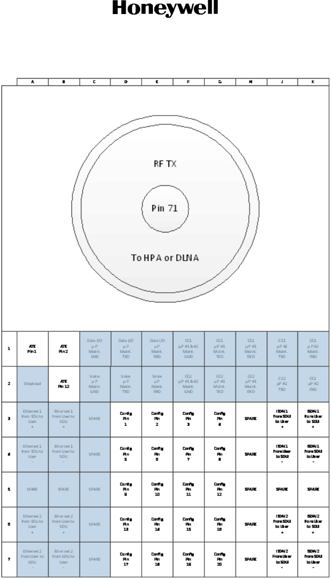
DRAFT
Page 3-4
17 Mar 2016
23-15-87
© Honeywell International Inc. Do not copy without express permission of Honeywell.
SYSTEM DESCRIPTION, INSTALLATION, AND MAINTENANCE MANUAL
ARINC 781-500 SDU and SCM
Figure 3-1. Top Plug Pin Deviations
Figure 3-2 shows the mid plug pin deviations outlined in gray.
DRAFT as of
4 Mar 2016
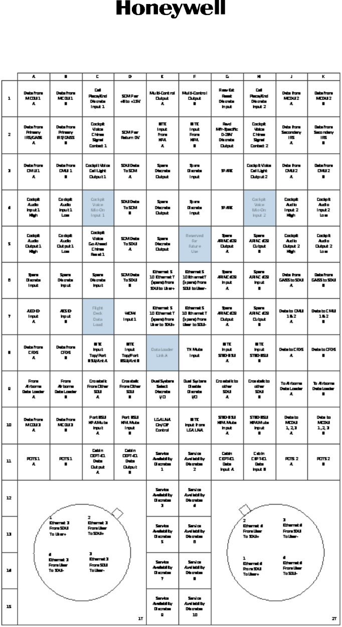
DRAFT
Page 3-5
17 Mar 2016
23-15-87
SYSTEM DESCRIPTION, INSTALLATION, AND MAINTENANCE MANUAL
ARINC 781-500 SDU and SCM
© Honeywell International Inc. Do not copy without express permission of Honeywell.
Figure 3-2. Mid Plug Pin Deviations
DRAFT as of
4 Mar 2016
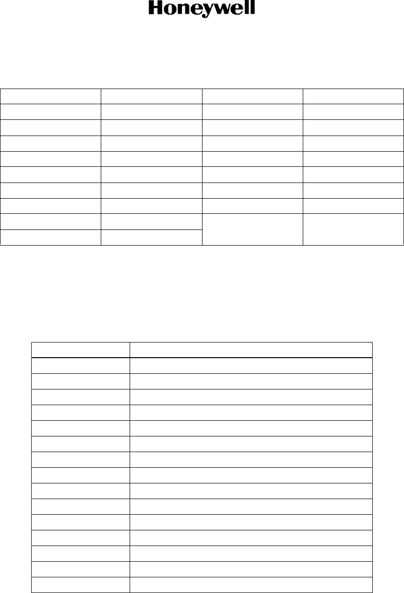
DRAFT
Page 3-6
17 Mar 2016
23-15-87
© Honeywell International Inc. Do not copy without express permission of Honeywell.
SYSTEM DESCRIPTION, INSTALLATION, AND MAINTENANCE MANUAL
ARINC 781-500 SDU and SCM
B. SCM
The SCM uses a 15-pin D-type male connector and locking screws. Pin assignments are compliant
with ARINC Characteristic 781 and shown in Table 3-3.
Table 3-2. SDU Front Connector DSUB and RJ45 Pin Assignment
9S DSUB Pin Number Description RJ45 Pin Number Description
1NC1RX+
2TX2RX-
3RX3TX+
4NC4NC
5GND5 NC
6NC6TX-
7NC7NC
8NC8NC
9NC
Table 3-3. SCM D-Type Connector Pin Assignment
Pin Number Description
1 Data to SDU A (RS422)
2 Data to SDU B (RS422)
3 Data from SDU A (RS422)
4 Data from SDU B (RS422)
5 Reserved - RS232 Gnd (used for shop loading)
6Spare
7 Chassis Ground
8 Power Input +8 V to +15 V
9 Reserved - Enable RS232 (used for shop loading)
10 Reserved - 0 V strap output (used for shop loading)
11 Spare
12 Reserved - RS232 Tx (used for shop loading)
13 Reserved - RS232 Rx (used for shop loading)
14 Spare
15 Power Return 0 V
DRAFT as of
4 Mar 2016

DRAFT
Page 3-7
17 Mar 2016
23-15-87
SYSTEM DESCRIPTION, INSTALLATION, AND MAINTENANCE MANUAL
ARINC 781-500 SDU and SCM
© Honeywell International Inc. Do not copy without express permission of Honeywell.
5. Owners Requirements Table (ORT)
A. ORT Overview
The A781-500 system includes a secure and user ORT. Secure ORT files must be certified for the
aircraft type on which the equipment is installed. Items in user ORT files can be modified by
individual customers and may be customized to an individual aircraft.
You can change secure ORT parameters only by uploading an ORT file. To obtain a secure ORT
file, contact RC Product Support.
The ORT file is loaded on to the SCM using an ARINC 615A data loader. You can only load ORT
data when the aircraft is on the ground and the data load discrete is asserted. When the SDU boots,
it compares the ORT file in its memory to that in the SCM. If the ORT files do not match, the SDU
loads the file from the SCM into its memory.
Some user ORT parameters can be modified in the SDU ORT. You can reset the SDU ORT to the
default values stored in the SCM in the maintenance menus.
To modify the user ORT parameters, use the ORT Application. To obtain the ORT Application,
contact RC Product Support.
For more information see the following guides:
• Publication No. D201511000062, A781-500 User ORT User Guide
• Publication No. D201511000064, A781-500 Secure ORT User Guide
• Publication No. D201511000061, A781-500 ORT Application Install Manual.
6. Passive Intermodulation (PIM) Test
This section describes the passive intermodulation test. You must execute the PIM test after installation
if the A781-500 SDU operates in SBB mode.
A. Overview
To meet Inmarsat requirements for SBB operation, the A781-500 SDU can test for passive
intermodulation effects. The PIM test verifies that the transmit signal from the A781-500 SDU does
not degrade or interfere with the receive signals as a result of PIM.
A781-500 SDU can only perform the PIM test when the aircraft is on the ground.
When the A781-500 SDU logs on to the SBB network, the network assigns the terminal two
channels for PIM testing. These channels are not used by other terminals so that the A781-500
SDU can transmit the test frequencies without interfering with other satellite communication
equipment or the Inmarsat satellite.
B. PIM Requirements
In order to successfully perform the PIM test, the aircraft and the satellite communication system
must meet the following requirements:
• The A781-500 SDU must have successfully logged on to a satellite that is visible at the test
location within the last 168 hours (7 days).
DRAFT as of
4 Mar 2016
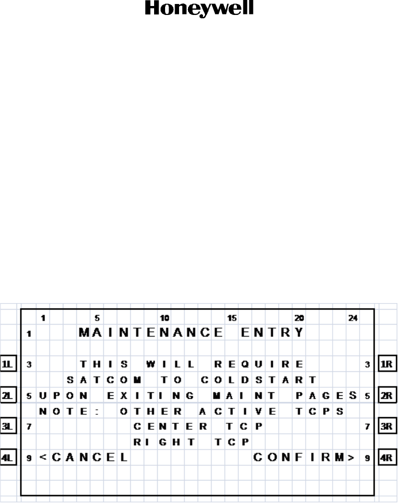
DRAFT
Page 3-8
17 Mar 2016
23-15-87
© Honeywell International Inc. Do not copy without express permission of Honeywell.
SYSTEM DESCRIPTION, INSTALLATION, AND MAINTENANCE MANUAL
ARINC 781-500 SDU and SCM
• The aircraft has to be outside the hangar and far away from the hangars and towers in order to
obtain good results.
• The aircraft must be facing due north in the northern hemisphere, and due south in the south-
ern hemisphere.
C. PIM Test
To run the PIM test, you must be in maintenance mode.You can only access the TCP maintenance
menus when the plane is on the ground and classic services are logged off.
To start the PIM test:
(a) In the TCP CONFIG 1/5 menu, type the protection level code in the scratchpad, and
press the button next to PROT LEVEL CODE.
NOTE: Contact RC Product Support for the PROT level code.
The SATCOM Maintenance Entry page appears.
(b) To enter maintenance mode, press the button next to CONFIRM.
The MAINTENANCE MENU appears.
(c) To start the PIM test, press the button next to INTERMOD TEST.
(d) Press the button next to RUN in order to initiate the PIM test.
The PIM test starts. The test takes about 5 minutes.
DRAFT as of
4 Mar 2016

DRAFT
Page 3-9
17 Mar 2016
23-15-87
SYSTEM DESCRIPTION, INSTALLATION, AND MAINTENANCE MANUAL
ARINC 781-500 SDU and SCM
© Honeywell International Inc. Do not copy without express permission of Honeywell.
D. PIM Test Results
Table 3-4 displays possible PIMBIT status messages. The status messages are displayed on the
INTERMOD page.
Table 3-4. PIM Test Conditions
Test Status Description Action
READY Conditions necessary to perform test
are present, no test is in progress and
no test has been run to completion.
No action required.
IN PROGRESS Test is in progress. No action required.
PASS Test has completed successfully and
passed the ORT specified criteria.
No action required.
FAIL Test has completed but does not
meet pass with the ORT specified
criteria.
See "PIM Test Overall Status" on
page 3-10.
SUSPECT Test results are suspect (possible
causes are: unstable noise,
mismatched test frequencies).
Repeat the test.
HSR NOT READY High stability oscillator is warming. Wait for the status to change to
READY.
NAV DATA UNAVAIL Test cannot be executed as
navigation information is not present.
SDU is in safe mode. Navigation
data must be provided in order for
the SATCOM system to work,
including PIMBIT. Ensure the SDU
can receive navigation data. Wait for
the status to change to READY and
repeat the test.
ANT NOT READY Test cannot be executed as
communication with Antenna has not
been established. This could indicate
an Antenna or D/LNA fault.
Problem with the antenna. PIMBIT
cannot be executed until
communication with the antenna is
established. Check the cable
connections of the SDU and the
antenna and check the antenna
status. "BITE" on page 4-6. Once the
connection has been established,
wait for PIMBIT status to change to
READY and run PIMBIT.
SDU FAULT Self test has found internal SDU fault. Check BITE status. See "BITE" on
page 4-6.
TEST FREQ UNAVAIL No test frequencies less than 168
hours old available for a viable
satellite.
Log on to an I-4satellite to obtain test
frequencies from the SBB bulletin.
Log off, ensure the status changes to
READY and run PIMBIT.
DRAFT as of
4 Mar 2016

DRAFT
Page 3-10
17 Mar 2016
23-15-87
© Honeywell International Inc. Do not copy without express permission of Honeywell.
SYSTEM DESCRIPTION, INSTALLATION, AND MAINTENANCE MANUAL
ARINC 781-500 SDU and SCM
(1) PIM Test Overall Status
At the end of the PIM test, the A781-500 SDU displays the test results on the TCP screen.
The TCP displays the overall PIM status and results for each direction. If the overall status is
PASS, the SDU can continue to use SBB services.
If the overall status is FAIL:
• Check the cable connections of the antenna and the SDU.
• Check the direction in which the test failed and verify that the antenna is not blocked in
that direction. Refer to "Directional PIM Test Results" on page 3-10.
(2) Directional PIM Test Results
The SDU performs the PIM test with the antenna pointing in different directions and displays
the results of the test in each direction. If the overall status of the PIM test is FAIL, you can
check the specific directions in which the test failed.
For each direction, the PIM test results provide:
• Overall Status—pass or fail
• The direction coordinates
• The signal degradation—pass level is adjustable in Secure ORT
• Possible interference—interference caused by environmental factors, not the SDU
transmit frequencies. Interference indicates that the SDU received a signal in the receive
band even when it wasn’t transmitting, therefore an external signal may be interfering
with communication in that direction
• Signal and noise levels before and after the test—the SDU uses this information to check
for possible interference.
SAFE MODE Configuration error detected.
Possible causes:
• Strapping parity error.
• FMPA messages when
standalone mode strapped.
• Secure ORT parameters are not
available.
SATCOM cannot operate until
configuration fault is eliminated (see
description for possible causes).
Once the fault is eliminated, wait for
the status to change to READY and
run PIMBIT.
NOT ALLOWED IN AIR Air/Ground status indicates in air.
PIMBIT cannot be performed while
the aircraft is in the air.
Run PIMBIT when the aircraft is on
the ground.
Table 3-4. PIM Test Conditions
Test Status Description Action
DRAFT as of
4 Mar 2016

DRAFT
Page 3-11
17 Mar 2016
23-15-87
SYSTEM DESCRIPTION, INSTALLATION, AND MAINTENANCE MANUAL
ARINC 781-500 SDU and SCM
© Honeywell International Inc. Do not copy without express permission of Honeywell.
7. Installation and Engineering Drawings
This section contains the Outline and Installation diagrams, and Interconnection and Contact Assignment
drawings for the SDU and SCM.
All foldout pages are odd-numbered and not-backed for print production purposes.
A. Outline and Installation Drawings
The Outline and Installation drawings on Page 3-23 thru Page 3-28 show the physical
characteristics of the SDU and SCM, and provide installation data for the system.
B. System Interconnect Drawings
System Interconnect drawings on Page 3-13 thru Page 3-22 show the interconnection details for
the SDU and SCM.
DRAFT as of
4 Mar 2016

DRAFT
Page 3-12
17 Mar 2016
23-15-87
© Honeywell International Inc. Do not copy without express permission of Honeywell.
SYSTEM DESCRIPTION, INSTALLATION, AND MAINTENANCE MANUAL
ARINC 781-500 SDU and SCM
Blank Page
DRAFT as of
4 Mar 2016
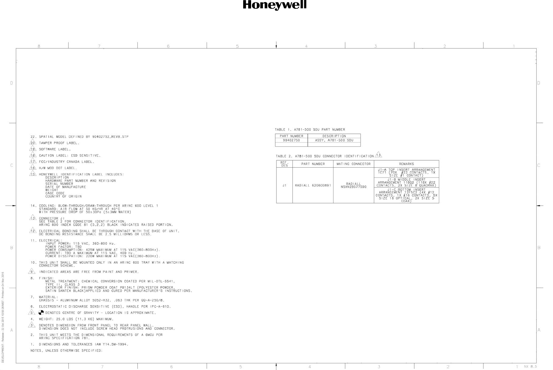
DRAFT
System Description, Installation, and Maintenance Manual
ARINC 781-500 SDU and SCM
3-13
17 Mar 2016
23-15-87
© Honeywell International Inc. Do not copy without express permission of Honeywell.
Figure 3-3. A781-500 SDU Outline and Installation Drawing, PN 90402752 (Sheet 1 of 3)
DRAFT as of
4 Mar 2016

DRAFT
System Description, Installation, and Maintenance Manual
ARINC 781-500 SDU and SCM
3-14
17 Mar 2016
23-15-87
© Honeywell International Inc. Do not copy without express permission of Honeywell.
Blank Page
DRAFT as of
4 Mar 2016
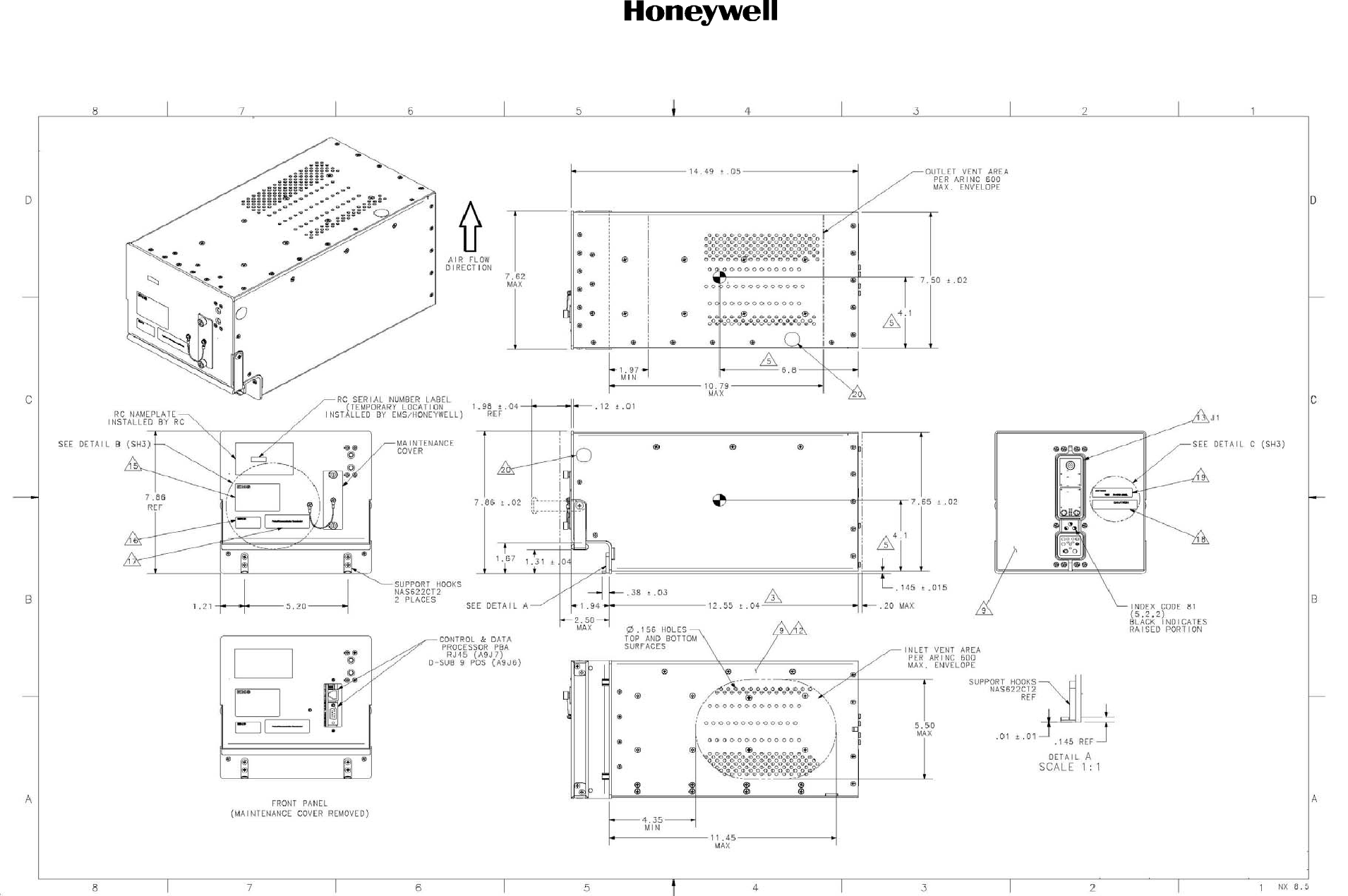
DRAFT
System Description, Installation, and Maintenance Manual
ARINC 781-500 SDU and SCM
3-15
17 Mar 2016
23-15-87
© Honeywell International Inc. Do not copy without express permission of Honeywell.
Figure 3-4. A781-500 SDU Outline and Installation Drawing, PN 90402752 (Sheet 2 of 3)
DRAFT as of
4 Mar 2016

DRAFT
System Description, Installation, and Maintenance Manual
ARINC 781-500 SDU and SCM
3-16
17 Mar 2016
23-15-87
© Honeywell International Inc. Do not copy without express permission of Honeywell.
Blank Page
DRAFT as of
4 Mar 2016
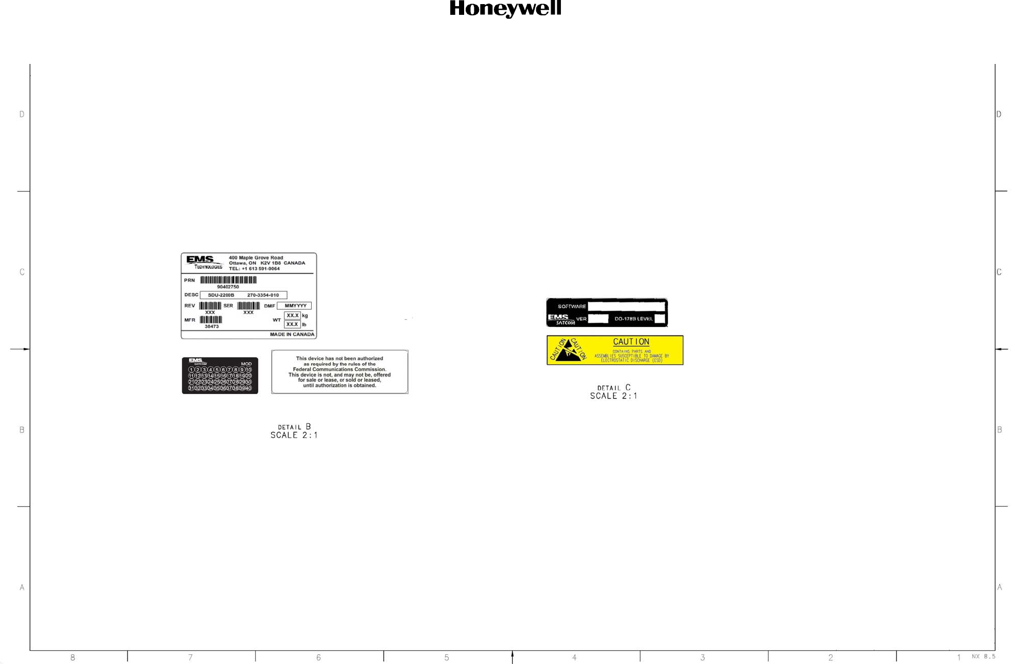
DRAFT
System Description, Installation, and Maintenance Manual
ARINC 781-500 SDU and SCM
3-17
17 Mar 2016
23-15-87
© Honeywell International Inc. Do not copy without express permission of Honeywell.
Figure 3-5. A781-500 SDU Outline and Installation Drawing, PN 90402752 (Sheet 3 of 3)
DRAFT as of
4 Mar 2016

DRAFT
System Description, Installation, and Maintenance Manual
ARINC 781-500 SDU and SCM
3-18
17 Mar 2016
23-15-87
© Honeywell International Inc. Do not copy without express permission of Honeywell.
Blank Page
DRAFT as of
4 Mar 2016
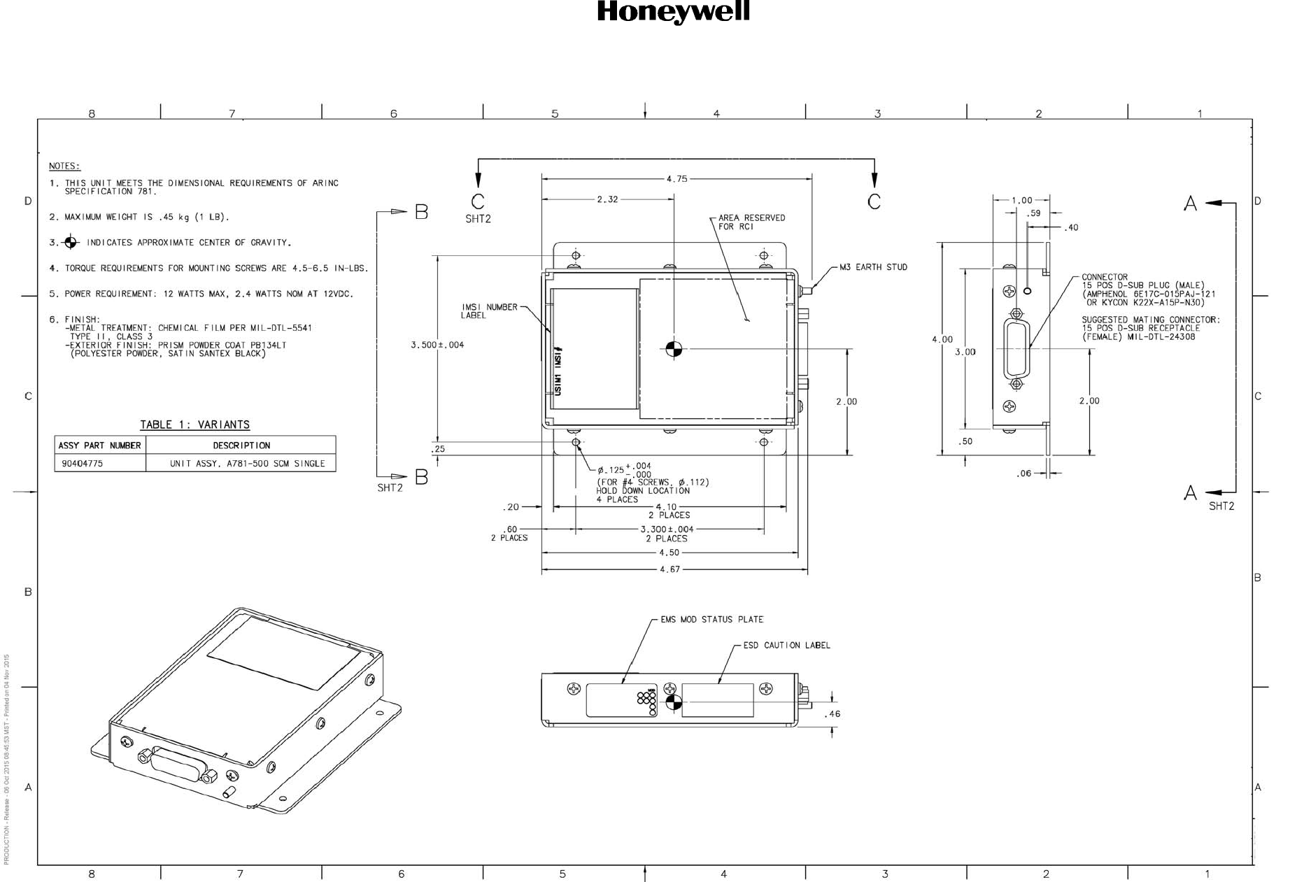
DRAFT
System Description, Installation, and Maintenance Manual
ARINC 781-500 SDU and SCM
3-19
17 Mar 2016
23-15-87
© Honeywell International Inc. Do not copy without express permission of Honeywell.
Figure 3-6. A781-500 SCM Outline and Installation Drawing, PN 90404776 (Sheet 1 of 2)
DRAFT as of
4 Mar 2016

DRAFT
System Description, Installation, and Maintenance Manual
ARINC 781-500 SDU and SCM
3-20
17 Mar 2016
23-15-87
© Honeywell International Inc. Do not copy without express permission of Honeywell.
Blank Page
DRAFT as of
4 Mar 2016
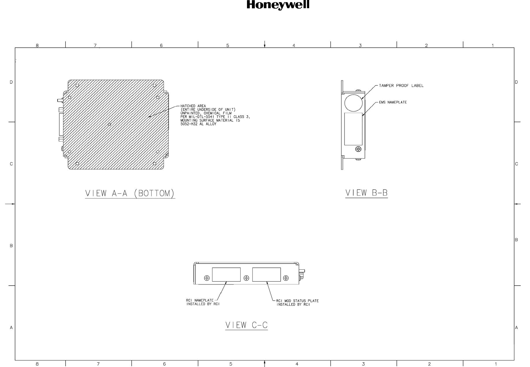
DRAFT
System Description, Installation, and Maintenance Manual
ARINC 781-500 SDU and SCM
3-21
17 Mar 2016
23-15-87
© Honeywell International Inc. Do not copy without express permission of Honeywell.
Figure 3-7. A781-500 SCM Outline and Installation Drawing, PN 90404776 (Sheet 2 of 2)
DRAFT as of
4 Mar 2016

DRAFT
System Description, Installation, and Maintenance Manual
ARINC 781-500 SDU and SCM
3-22
17 Mar 2016
23-15-87
© Honeywell International Inc. Do not copy without express permission of Honeywell.
Blank Page
DRAFT as of
4 Mar 2016
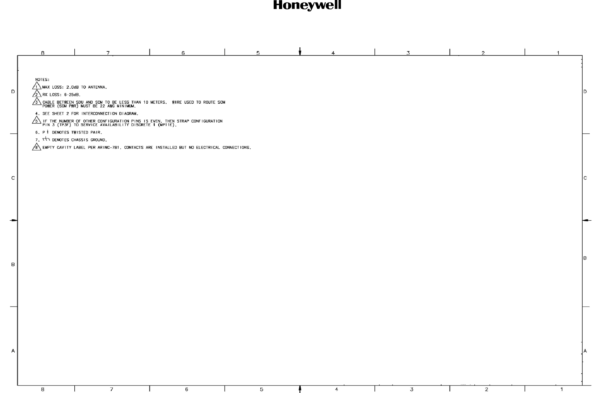
DRAFT
System Description, Installation, and Maintenance Manual
ARINC 781-500 SDU and SCM
3-23
17 Mar 2016
23-15-87
© Honeywell International Inc. Do not copy without express permission of Honeywell.
Figure 3-8. A781-500 System Interconnect Drawing, PN 90402748 (Sheet 1 of 3)
DRAFT as of
4 Mar 2016

DRAFT
System Description, Installation, and Maintenance Manual
ARINC 781-500 SDU and SCM
3-24
17 Mar 2016
23-15-87
© Honeywell International Inc. Do not copy without express permission of Honeywell.
Blank Page
DRAFT as of
4 Mar 2016
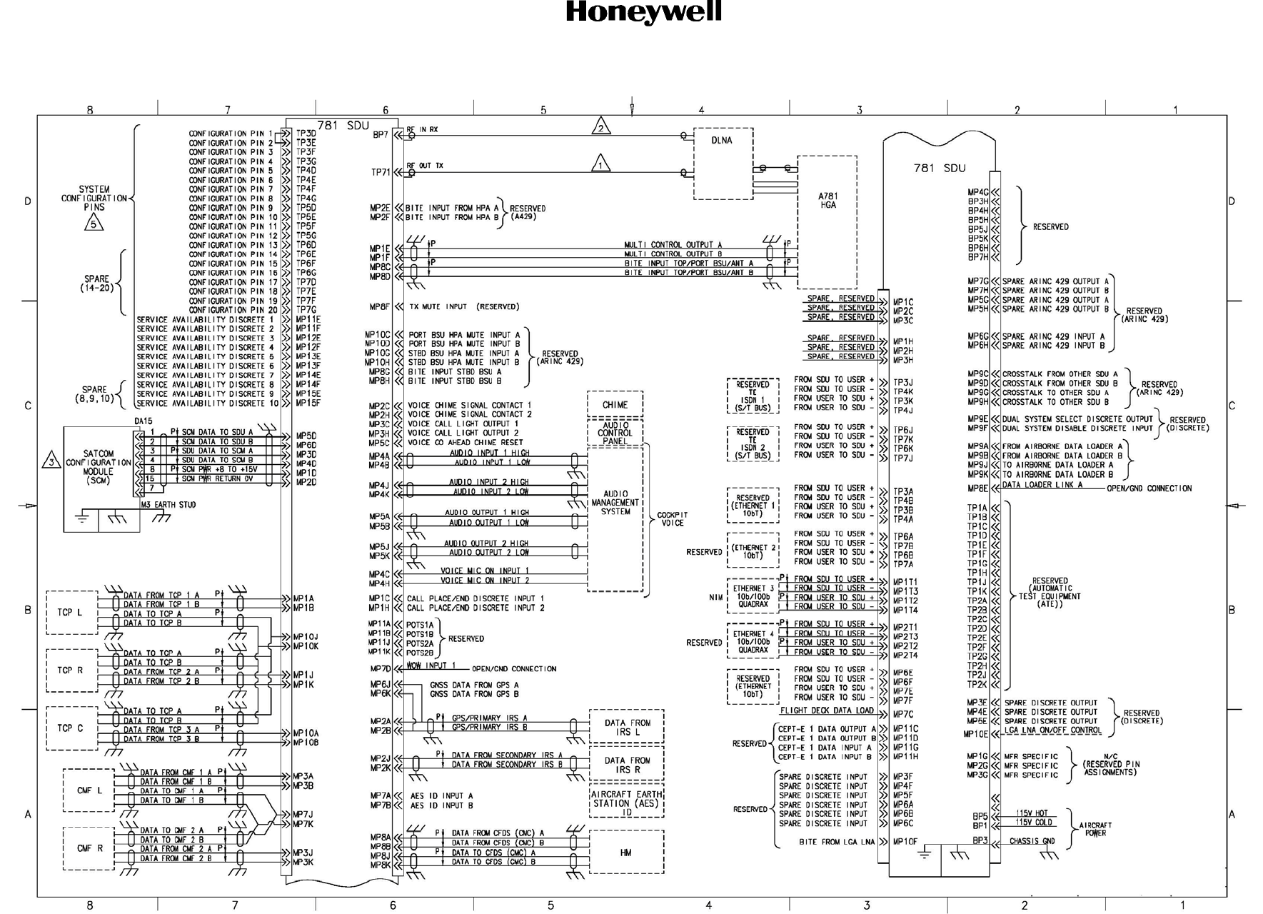
DRAFT
System Description, Installation, and Maintenance Manual
ARINC 781-500 SDU and SCM
3-25
17 Mar 2016
23-15-87
© Honeywell International Inc. Do not copy without express permission of Honeywell.
Figure 3-9. A781-500 System Interconnect Drawing, PN 90402748 (Sheet 2 of 3)
DRAFT as of
4 Mar 2016

DRAFT
System Description, Installation, and Maintenance Manual
ARINC 781-500 SDU and SCM
3-26
17 Mar 2016
23-15-87
© Honeywell International Inc. Do not copy without express permission of Honeywell.
Blank Page
DRAFT as of
4 Mar 2016
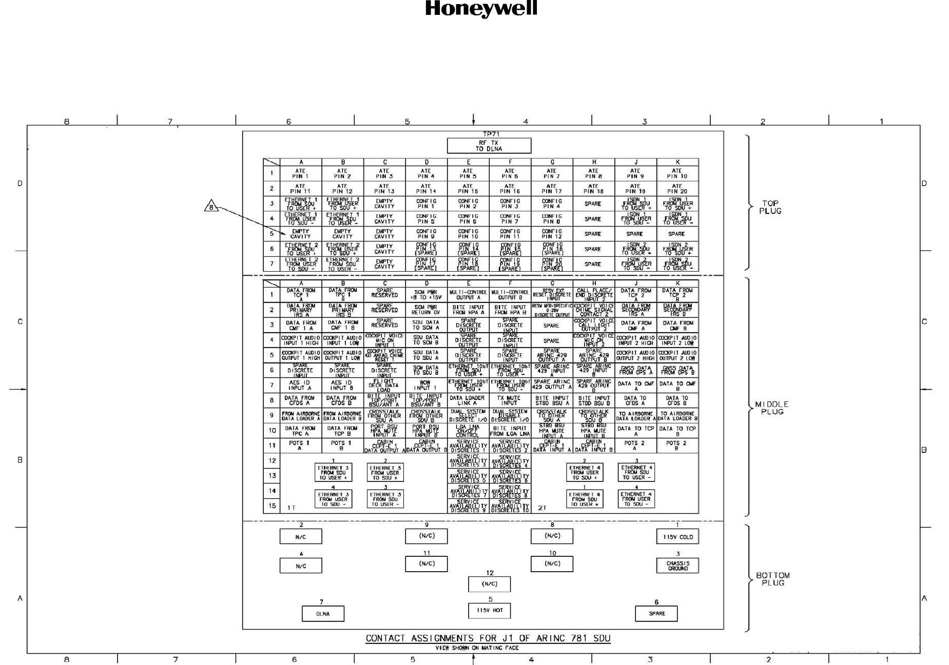
DRAFT
System Description, Installation, and Maintenance Manual
ARINC 781-500 SDU and SCM
3-27
17 Mar 2016
23-15-87
© Honeywell International Inc. Do not copy without express permission of Honeywell.
Figure 3-10. A781-500 System Interconnect Drawing, PN 90402748 (Sheet 3 of 3)
DRAFT as of
4 Mar 2016

DRAFT
System Description, Installation, and Maintenance Manual
ARINC 781-500 SDU and SCM
3-28
17 Mar 2016
23-15-87
© Honeywell International Inc. Do not copy without express permission of Honeywell.
Blank Page
DRAFT as of
4 Mar 2016

DRAFT
Page 4-1
17 Mar 2016
23-15-87
SYSTEM DESCRIPTION, INSTALLATION, AND MAINTENANCE MANUAL
ARINC 781-500 SDU and SCM
© Honeywell International Inc. Do not copy without express permission of Honeywell.
TESTING AND FAULT ISOLATION
This section provides test procedures to determine the operational readiness of SDU units.
All of the tests are to be performed when the SDU is installed on an aircraft and connected to a TCP.
There are no operational test procedures defined for the SCM. SCM health is determined by accessing the SDU
BITE information.
If the A781-500 equipment passes all tests in this section but does not function according to the installation
requirements, the fault may be with equipment or wiring outside the A781-500 system.
This section includes:
• Operational and Diagnostic Testing
• Troubleshooting and Fault Isolation
• Adjustment/Alignment Procedures
• Modification History.
NOTE: Depending on the version of software installed, the MPU menus described may differ from those shown
as examples in this manual.
1. Operational and Diagnostic Testing
This section includes the following sections:
• General
• Test and Fault Isolation Equipment Requirements
• SDU Maintenance Port Utility
• Operational and Diagnostic Test Procedures.
A. General
The A781-500 system requires testing for one of the following reasons:
• To verify the operational readiness of the system after installation on an aircraft
• To verify that a fault exists and produce system reports for troubleshooting purposes
• To verify the operational readiness of repaired LRUs after re-installation on an aircraft.
This section includes test and fault isolation procedures for the A781-500 system. All test and load
procedures require the A781-500 SDU MPU, which is accessed by connecting to the maintenance
port of the SDU.
B. Test and Fault Isolation Equipment Requirements
Table 4-1 lists the equipment required to access the SDU Maintenance Port Utility and perform
operational and diagnostic testing on the SDU.
DRAFT as of
4 Mar 2016
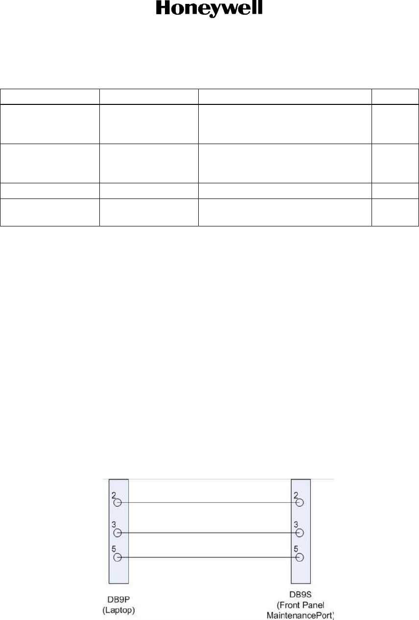
DRAFT
Page 4-2
17 Mar 2016
23-15-87
© Honeywell International Inc. Do not copy without express permission of Honeywell.
SYSTEM DESCRIPTION, INSTALLATION, AND MAINTENANCE MANUAL
ARINC 781-500 SDU and SCM
C. SDU Maintenance Port Utility
This section describes the SDU MPU and provides the connection and cabling details required to
access and use the program.
(1) Connecting to the MPU
The MautoPU provides a system interface for fault isolation and diagnostic procedures.
To use the SDU MPU:
(a) Using a 3/32 Allen key, remove the maintenance port cover.
(b) Connect an RS-232 and VT-100 terminal (computer operating a terminal emulation
program) to the RS-232 maintenance port interface of the SDU.
The maintenance port on the front panel of the SDU provides a direct connection to the MPU
using a DB9 connector.
Figure 4-1 provides cabling details for the SDU maintenance port.
Figure 4-1. Maintenance Cable
Table 4-1 List of Required Test Equipment
Item Equipment Specification Quantity
Computer Standard PC running VT-100 terminal emulator,
such as Hyper Terminal and equipped
with an RS-232 port.
1
VT-100 terminal
emulation program
HyperTerminal©,
ProComm Plus©, or
equivalent
Serial communication program using an
RS-232 port
1
Cable RS-232 cable Maximum length 25 feet 1
Allen key Standard 3/32 inch Allen key to fit a hex screw with
a 4/40 inch head.
1
DRAFT as of
4 Mar 2016

DRAFT
Page 4-3
17 Mar 2016
23-15-87
SYSTEM DESCRIPTION, INSTALLATION, AND MAINTENANCE MANUAL
ARINC 781-500 SDU and SCM
© Honeywell International Inc. Do not copy without express permission of Honeywell.
(a) Interface Requirements
A standard VT-100 compatible terminal running an emulator program (such as
HyperTerminal, ProComm Plus, or similar) provides the user interface to the SDU MPU.
The RS-232 terminal connection settings for SDU maintenance ports are listed in
Table 4-2.
(2) Using the SDU MPU
This section describes the basic procedures for using and navigating the SDU MPU.
NOTE: There are various levels of access to the MPU. Each level is protected by a different
password. This section describes the MPU functions available using the Level 1
password.
(a) Entering Passwords
You can enter the password any time after the SDU boots.
• To access Level 1 functions, type menu.
NOTE: The password does not appear on the screen when you type it.
(b) Navigating the SDU MPU
• To scroll through the available menus, press CTRL+N.
• To go to the previous menu, press CTRL+O.
• To refresh the menu screen or exit from a Reports Menu, press ESC.
(c) Selecting Menu Items
• To enable test or data entry functions, press the letter associated with the menu items.
(d) Selecting Reports
The reports available through the MPU enable users to view information about the
configuration and status of the SDU. This information is used to troubleshoot the
communication system on the aircraft.
To access reports:
Table 4-2 Maintenance Port Connection Settings
Parameter Setting
Character Format ASCII
Baud Rate 19200 bps
No. of bits 8
Parity None
Stop bits 1
Flow Control None
DRAFT as of
4 Mar 2016

DRAFT
Page 4-4
17 Mar 2016
23-15-87
© Honeywell International Inc. Do not copy without express permission of Honeywell.
SYSTEM DESCRIPTION, INSTALLATION, AND MAINTENANCE MANUAL
ARINC 781-500 SDU and SCM
1 In the MPU, press EQUAL SIGN (=).
A list of reports appears. Active reports show as toggled on. Inactive reports show
as toggled off.
2 To activate a report, type the report number, and then press ENTER.
NOTE: Multiple reports can be activated at the same time; type and enter each
report number separately.
3 To turn off individual, active reports, type the report number you want to toggle off,
and then press ENTER.
4 To turn off all active reports, press EQUAL SIGN (=), and then press X.
(3) Menu Item Descriptions
This section provides a brief description of the Level 1, MPU menu items used for test and
fault isolation procedures.
In active SDUs, menu screens display the firmware version.
NOTE: Depending on the version of software installed and the system configuration, the
menu and reports available to users may differ slightly from the reports described in
this document.
(a) Menu 1
Table 4-3 shows an example Menu 1 screen display.Table 4-3 describes the items
available in Menu 1.
(b) Menu 2
Table 4-4 describes the items available in Menu 2.
Table 4-3 Menu 1 Item Descriptions
Menu Item Description
Y: explain error status Reports error status when failure LED is illuminated. Displays OK if no error
exists.
F: print equipment
stats
Prints a list of the current equipment statistics, including temperature,
number of power-ups, hours of operation, time since power-up, and
processor usage.
Table 4-4 Menu 2 Item Descriptions
Menu Item Description
L: re-enter logon
password
Permits a user to enter a new access level password without having to
reboot the SDU.
Z: reset A781 SDU Enables a complete, soft reset of the SDU; once reset, the menu access
password must be re-entered.
DRAFT as of
4 Mar 2016

DRAFT
Page 4-5
17 Mar 2016
23-15-87
SYSTEM DESCRIPTION, INSTALLATION, AND MAINTENANCE MANUAL
ARINC 781-500 SDU and SCM
© Honeywell International Inc. Do not copy without express permission of Honeywell.
(c) Menu 3
Table 4-5 describes the items available in Menu 3.
D. Operational and Diagnostic Test Procedures
You can perform all test procedures presented in this section to test the total operational status of
the A781-500 system. You can conduct these operational tests for all equipment returned to service
after repair.
The procedures assume that the technical personnel are familiar with the test equipment used and
can operate the equipment to produce the required inputs and obtain the required results
(indications). Refer to the detailed operating procedures and descriptions of the SDU MPU included
in this section.
V: get firmware versions Displays the kernel and application software versions for the Control
Processor, Data I/O Processor, Channel Cards.
C: query loss of cooling
mode
Indicates if loss of cooling mode is active or inactive.
Table 4-5 Menu 3 Item Descriptions
Menu Item Description
F: list call log Lists Classic call logs for the following events:
• Successful Aero Log-on
• Air-to-ground calls accepted by the SDU
• Ground-to-air calls accepted by the SDU
Lists SBB call logs for the following events:
• Attachment or modification of attachment, including change of beam ID
• Creation or deletion of primary or secondary contexts
O: list DIO ORT Lists of ORT items destined for the Data Processor in human readable
form.
Y: verify CP ORT Verifies if file name of the internal copies of the Secure and User ORT
are valid or corrupted.
G: clear call log Clears the call log after a confirmation.
H: list SCM/CP ORT Lists ORT settings and how they were configured (either by default or
through the maintenance port, or via SCM ORT files). “Set by
maintenance port” indicates that the ORT parameter is set by the
maintenance port.
Table 4-4 Menu 2 Item Descriptions (Continued)
Menu Item Description
DRAFT as of
4 Mar 2016

DRAFT
Page 4-6
17 Mar 2016
23-15-87
© Honeywell International Inc. Do not copy without express permission of Honeywell.
SYSTEM DESCRIPTION, INSTALLATION, AND MAINTENANCE MANUAL
ARINC 781-500 SDU and SCM
CAUTION: ONLY AUTHORIZED TECHNICAL PERSONNEL WHO ARE TRAINED IN
GENERAL AVIA1.57 TION WORKMANSHIP AND HAVE A BASIC
UNDERSTANDING OF SATCOM SYSTEMS SHOULD PERFORM THE
OPERATIONAL AND DIAGNOSTIC TEST PROCEDURES IN THIS MANUAL.
CAUTION: CHANGES TO DEFAULT VALUES FOR SOME MENU FUNCTIONS MAY
SERIOUSLY DEGRADE SYSTEM OPERATION.
NOTE: This manual describes the basic MPU functions, menus, and reports required for the testing
and fault isolation procedures presented in this section. Consult RC Product Support before
entering any unfamiliar menu selections not described in this manual.
NOTE: Using a terminal emulation program, open a log file and save all test results for future
reference and test records.
Refer to the Outline and Installation diagrams (Figure 3-1 to Figure 3-6) and the Interconnection
and Contact Assignment drawings (Figure 3-7 to Figure 3-9) for additional information.
(1) Test Setup Procedure
The test setup procedure is presented in Table 4-6.
(2) Installation and Operational Verification Tests
To verify that the A781-500 system is ready for operation, use the following procedures:
• Power-On Test
•BITE
(a) Power-On Test
To complete the power-on test, follow the steps in Table 4-7.
Table 4-6 Test Setup Procedure
Step Action
1.0 Make sure that the SDU is powered down and disconnected from the power source.
2.0 Using a 3/32 Allen key, remove the maintenance port cover.
3.0 Connect a maintenance cable to the SDU front-panel maintenance port connector.
4.0 Connect the other end of the cable to the serial port of the computer.
5.0 Open a log file to capture all test data. A log file is a text capture of the ASCII traffic
between the computer attached to the maintenance port and the SDU.
6.0 Follow the procedures in "Installation and Operational Verification Tests" on page 4-6.
Table 4-7 Power-On Test Procedure
Step Action
1.0 Follow the test setup procedure in Table 4-6 on page 6.
2.0 Power-on the SDU.
DRAFT as of
4 Mar 2016

DRAFT
Page 4-7
17 Mar 2016
23-15-87
SYSTEM DESCRIPTION, INSTALLATION, AND MAINTENANCE MANUAL
ARINC 781-500 SDU and SCM
© Honeywell International Inc. Do not copy without express permission of Honeywell.
(b) BITE
If equipment connected to the A781-500 system provides wrong information or does not
provide a signal to the A781-500 SDU, the SDU cannot function properly.
The SATCOM BITE menu provides information about the results from BITE for various
parts of the A781-500 system.
To check the BITE status, follow the steps in Table 4-.
(3) Post Test
When testing is completed, follow the steps in Table 4-9.
3.0 Check the status of the front panel LEDs. Verify that the green LED flashes for 60
seconds and then turns off. Verify that the red LED is not illuminated. For more
information about the LED signals, refer to "LEDs" on page 1-9.
4.0 Follow the BITE test procedure in "BITE" on page 4-7.
Table 4-8 Power-On Test Procedure
Step Action
1.0 Using the TCP, navigate to the SATCOM BITE page. See "Viewing BITE Information"
on page 2-15.
2.0 Confirm that the following report a status of OK:
•SDU
• Sub System Health
•SCM
• SYS BUS
• Sub System BUS
•RF Path
3.0 If BITE fails the SDU or SCM, remove the component from service and return it to
RC—see "Maintenance and Repair" on page 5-1. Return the UUT along with a
hardcopy printout of the recorded (captured) log file of the test results. Indicate the
date of the test and the serial number of the UUT on the test documentation.
4.0 If BITE fails a component other than the A781-500 SDU or SCM, verify the operation
of that component and test the satellite communication system again. See
"Troubleshooting and Fault Isolation" on page 4-8
5.0 If the Unit Under Test (UUT) PASSED the test, the unit is ready for service.
6.0 Follow the procedures in "Post Test" on page 4-7.
Table 4-7 Power-On Test Procedure (Continued)
Step Action
DRAFT as of
4 Mar 2016
DRAFT
Page 4-8
17 Mar 2016
23-15-87
© Honeywell International Inc. Do not copy without express permission of Honeywell.
SYSTEM DESCRIPTION, INSTALLATION, AND MAINTENANCE MANUAL
ARINC 781-500 SDU and SCM
2. Troubleshooting and Fault Isolation
This section provides troubleshooting procedures for A781-500 systems.
Troubleshooting procedures require data obtained using the TCP. For specific instructions on how to access
and use the TCP, refer to "Operating the MCDU" on page 2-2.
NOTE: All of the TCP menus discussed in this section are accessed from the SATCOM BITE menu.
A. Subsystem Health
The SATCOM SUBSY HLTH menu provides the BITE status of subsystem components.
To check the subsystem health, on the SATCOM BITE menu, press the button next to SUBSY
HLTH.
Figure 4-2 illustrates the SATCOM SUBSY HLTH menu.
Figure 4-2. SATCOM Subsystem Health Menu
Table 4-10 describes the information available on the SATCOM SUBSY HLTH menu.
Table 4-9 Post Test Procedure
Step Action
1.0 Save the log file of the test results (or data) for future reference.
2.0 Remove power from the SDU that was tested and from all other test equipment.
3.0 Disconnect test equipment from the SDU.
4.0 Replace the maintenance-port connector cover (if it was removed during the test
setup).
1 5 10 15 20 24
1SA TCOM SUBSY HLTH
LNA
1L 3 OK 31R
ANT
2L 5 OK 52R
CONF I G PAR I TY
3L 7 OK 73R
4L 9<RETURN 94R
DRAFT as of
4 Mar 2016

DRAFT
Page 4-9
17 Mar 2016
23-15-87
SYSTEM DESCRIPTION, INSTALLATION, AND MAINTENANCE MANUAL
ARINC 781-500 SDU and SCM
© Honeywell International Inc. Do not copy without express permission of Honeywell.
B. SATCOM System Bus
The SATCOM SYSTEM BUS menu provides information about the bus status of equipment outside
the A781-500 system. SATCOM services are not available if the equipment does not operate or
communicate properly.
To check the bus status, on the SATCOM BITE menu, press the button next to SYS BUS.
Figure 4-3 illustrates the SATCOM System Bus menu.
Table 4-10 SATCOM Subsystem Health Menu
Label Description Action
LNA Reports the status of the LNA as OK, NO DATA (if
golden label 350 from the antenna is missing or
HGA is disconnected), TEST, or FAULT. The LNA
status matches the HDA status.
If the status is NO DATA, check
the bus connections from the
Antenna and check the speed of
bus.
If the status is FAULT, test or
troubleshoot the LNA equipment.
ANT Reports the status of the HGA as OK, FAULT,
TEST, or NO DATA.
If the status is FAULT, test or
troubleshoot the HGA equipment.
If the status is NO DATA check the
ARINC 429 bus from the Antenna.
FMPA Reports the status of the FMPA as OK, FAULT, NO
DATA, or NONE. If there is no FMPA configured,
the reported status is NONE.
If the status is FAULT, return the
FMPA to RC, the equipment
supplier. If the status is NO DATA
check the cable to the FMPA.
CONFIG
PARITY
Reports the status of the rear connector
configuration parity as OK (parity is odd) or FAULT
(parity is not odd). This status can be different from
the setting of Bit 25 in Label 350 to the CMC, which
is also set if the secure ORT is missing or invalid.
If the status is FAULT, check
strapping—a non-supported
configuration may be strapped.
DRAFT as of
4 Mar 2016
DRAFT
Page 4-10
17 Mar 2016
23-15-87
© Honeywell International Inc. Do not copy without express permission of Honeywell.
SYSTEM DESCRIPTION, INSTALLATION, AND MAINTENANCE MANUAL
ARINC 781-500 SDU and SCM
Figure 4-3. SATCOM System Bus Menu
Table 4-11 describes the information available on the SATCOM SYS BUS menu.
1 5 10 15 20 24
1 S AT COM SYS BUS 1/2
CFDS INACTIVE
1L 3 TCP#1 OK
31R
TCP# 2 OK
2L 5 TCP#3 OK
52R
IRS- PRI OK
3L 7 IRS-SEC OK 7 3R
4L 9<RETURN 94R
1 5 10 15 20 24
1 S AT COM SYS BUS 2/2
CMU#1 INACTIVE
1L 3 CMU#2 OK
31R
GNSS OK
2L 5 AES ID OK 52R
3L 7 73R
4L 9<RETURN 94R
DRAFT as of
4 Mar 2016

DRAFT
Page 4-11
17 Mar 2016
23-15-87
SYSTEM DESCRIPTION, INSTALLATION, AND MAINTENANCE MANUAL
ARINC 781-500 SDU and SCM
© Honeywell International Inc. Do not copy without express permission of Honeywell.
C. Thermal Status
As shown in Figure 4-4, the SATCOM OVERTEMP menu reports the thermal status of system
components.
To check the thermal status, on the SATCOM BITE menu, press the button next to OVERTEMP.
Table 4-11 Bus Status Indicators
Bus Status
INACTIVE NO DATA NONE OK
CFDS No labels of correct
speed on bus.
The expected Golden
label (227) is not
present.
The bus is not
installed.
The expected Golden
label is present and the
bus is active at the
correct speed.
CFDS The A781-500 does not support or receive input from the CFDS. Therefore the status will
always be NONE.
TCP No labels of correct
speed on bus.
The expected Golden
label (377) is not
present.
The secure ORT
parameter indicates
the bus is not installed.
The expected Golden
label is present and the
bus is active at the
correct speed.
IRS - PRI No labels of correct
speed on bus.
The expected Golden
label (310) is not
present, i.e. Label 310
or Label 254,
depending on ORT
selection.
N/A
(Primary IRS always
present on this
aircraft.)
The expected Golden
label is present and the
bus is active at the
correct speed.
IRS - SEC No labels of correct
speed on bus.
The expected Golden
label (310) is not
present.
The IRS2Type secure
ORT parameter
specifies whether it is
connected or not
connected.
The expected Golden
label is present and the
bus is active at the
correct speed.
GNSS No labels of correct
speed on bus.
The expected Golden
label (110) is not
present.
The secure ORT
parameter indicates
the bus is not installed.
The expected Golden
label is present and the
bus is active at the
correct speed.
AES ID No labels of correct
speed on bus.
The expected Golden
label (275) is not
present.
The secure ORT
parameter indicates
the bus is not installed.
The expected Golden
label is present and the
bus is active at the
correct speed.
CMU No labels of correct
speed on bus.
The expected Golden
label (270) is not
present.
The secure ORT
parameter indicates
the bus is not installed.
The expected Golden
label is present and the
bus is active at the
correct speed.
DRAFT as of
4 Mar 2016
DRAFT
Page 4-12
17 Mar 2016
23-15-87
© Honeywell International Inc. Do not copy without express permission of Honeywell.
SYSTEM DESCRIPTION, INSTALLATION, AND MAINTENANCE MANUAL
ARINC 781-500 SDU and SCM
Figure 4-4. SATCOM Overtemp Menu
Table 4-12 describes the information available on the SATCOM OVERTEMP menu.
D. SCM Health
As shown in Figure 4-5, the SATCOM SCM menu reports the status of the communication buses
to the SCM and the status of the secure and user configuration tables.
Table 4-12 SATCOM OVERTEMP Menu
Label Description Action
SDU Reports the SDU thermal status
as OK or FAIL.
If the status is FAIL, check the fan operation and
temperature at the location of the equipment.
HGA Reports the HGA thermal status
as OK, NO DATA, or FAIL.
If the status is FAIL, check the fan operation and
temperature at the location of the equipment.
If the status is NO DATA, check data bus connection.
FMPA Reports the FMPA thermal status
as OK, NO DATA, or FAIL.
If the status is FAIL, check the fan operation and
temperature at the location of the equipment.
1 5 10 15 20 24
1 SATCOM OVERTEM
P
SDU
1L 3 OK 31R
ANT
2L 5 FAIL 52R
3L 7 73R
4L 9<RE TURN 94R
DRAFT as of
4 Mar 2016
DRAFT
Page 4-13
17 Mar 2016
23-15-87
SYSTEM DESCRIPTION, INSTALLATION, AND MAINTENANCE MANUAL
ARINC 781-500 SDU and SCM
© Honeywell International Inc. Do not copy without express permission of Honeywell.
Figure 4-5. SATCOM SCM Menu
Table 4-13 describes the information available on the SATCOM SCM menu.
E. Subsystem Bus Status
As shown in Figure 4-6, the SATCOM SUBSY BUS menu reports the status of all subsystem buses
that provide communication between the components of the system.
Table 4-13 SATCOM SCM Menu
Label Description Action
STATUS Reports the SCM status as OK or FAIL. If the status is FAIL, return the SCM to
RC the equipment supplier.
BUS
TO/FROM
Reports the status of the bus to the SCM as
OK or FAIL.
If the status is FAIL, check the
connections to the SCM.
OSS Reports the status of the Secure ORT as
one of the following:
NOT LOADED – No ORT in SCM memory.
OK – Secure ORT is valid.
INVALID – The Secure ORT is corrupted or
otherwise invalid and must be reloaded.
If the status is INVALID or NOT
LOADED, load a SECURE ORT file.
AMI Reports the status of the User ORT as one
of the following:
NOT LOADED – No ORT in SCM memory.
OK – User ORT is valid.
INVALID – The User ORT is corrupted or
otherwise invalid and must be reloaded.
If the status is INVALID or NOT
LOADED, load a USER ORT file.
1 5 10 15 20 24
1 SATCOM SCM
STATUS OSS
1L 3 OK OK 31R
BUS TO/ FROM AM I
2L 5 OK OK 52R
3L 7 73R
4L 9<RE TURN 94R
DRAFT as of
4 Mar 2016
DRAFT
Page 4-14
17 Mar 2016
23-15-87
© Honeywell International Inc. Do not copy without express permission of Honeywell.
SYSTEM DESCRIPTION, INSTALLATION, AND MAINTENANCE MANUAL
ARINC 781-500 SDU and SCM
Figure 4-6. SATCOM Subsystem Bus Menu
Table 4-14 describes the information available on the SATCOM SUBSY BUS menu. Fields are left
blank if the equipment is not included in the installation.
NOTE: Input and output are with respect to the SDU.
F. RF Path Status
As shown in Figure 4-7, the SATCOM RF PATH menu reports the status of the RF paths.
Table 4-14 SATCOM SUBSY BUS Menu
Label Description Action
ANT Reports the status of the input and
output buses for the antenna as OK,
NO DATA, or FAIL.
If status is NO DATA, label 350 is missing—
check the bus connections.
If status is FAIL, check antenna bus status.
1 5 10 15 20 24
1 S ATCOM SUBSY BUS
1L 3 IN-TOP-OUT 31R
ANT
2L 5 OK / OK 52R
3L 7 7 3R
4L 9<RE TURN 94R
DRAFT as of
4 Mar 2016
DRAFT
Page 4-15
17 Mar 2016
23-15-87
SYSTEM DESCRIPTION, INSTALLATION, AND MAINTENANCE MANUAL
ARINC 781-500 SDU and SCM
© Honeywell International Inc. Do not copy without express permission of Honeywell.
Figure 4-7. SATCOM RF Path Menu
Table 4-15 describes the information available on the SATCOM RF PATH menu.
G. USIM and Data Bus Status
As shown in Figure 4-8, the SATCOM USIM/DATA menu reports the status of the USIMs and data
buses of the system.
Table 4-15 SATCOM RF PATH Menu
Label Description
RX:DLNA-SDU Reports the status of the RF path from the DLNA to the SDU as OK or FAULT.
If the status is FAULT, check Rx RF cabling between the SDU and the antenna.
TX:SDU-ANT Reports the status of VSWR activity on the SDU-Antenna RF path as OK or
FAULT. If the status is FAULT, check Tx RF cabling between the SDU and the
antenna.
1 5 10 15 20 24
1 SA TCOM RF PATH
PATH VSWR
1L 3 31R
RX : SDU -DLNA
2L 5 OK N / A 52R
TX:SDU- DLNA
3L 7 N/A OK 73R
4L 9<RE TURN 94R
DRAFT as of
4 Mar 2016
DRAFT
Page 4-16
17 Mar 2016
23-15-87
© Honeywell International Inc. Do not copy without express permission of Honeywell.
SYSTEM DESCRIPTION, INSTALLATION, AND MAINTENANCE MANUAL
ARINC 781-500 SDU and SCM
Figure 4-8. SATCOM USIM/DATA Menu
Table 4-16 describes the information available on the USIM/Data menu.
Table 4-16 SATCOM USIM/DATA Menu
Label Description
USIM#1 Reports the status of USIM#1 bus as OK, WARMING, SBB LOG, FAULT, or N/A
if channel card 1 is not in SBB mode.
If status is FAULT, check that SIM card is not damaged and is properly inserted.
Power cycle after checking.
USIM#2 Reports the status of USIM#2 bus as N/A.
If status is FAULT, check that SIM card is not damaged and is properly inserted.
Power cycle after checking.
USIM#3 Reports the status of USIM#3 bus as N/A.
If status is FAULT, check that SIM card is not damaged and is properly inserted.
Power cycle after checking.
USIM#4 Reports the status of USIM#4 bus as N/A. If status is FAULT, check that SIM card
is not damaged and is properly inserted. Power cycle after checking.
ETH#1 Reports the status of ETH#1 bus as DISABLED, LINK, or NO LINK.
ETH#2 Reports the status of ETH#2 bus as DISABLED, LINK, or NO LINK.
QUAD ETH#3 Reports the status of QUAD ETH#3 bus as DISABLED, LINK, or NO LINK.
QUAD ETH#4 Reports the status of QUAD ETH#4 bus as DISABLED, LINK, or NO LINK.
ETH#5 Reports the status of ETH#5 bus as DISABLED, LINK, or NO LINK.
NOTE: Only Ethernet 3 is fully supported. Ethernet 1, 2, and 5 are not supported and Ethernet 4
is only used for application data loading.
1 5 10 15 20 24
1 SATCOM USIM/DATA
USIM#1 ETH#2
1L 3 OK D I SABLED 31R
US I M# 4
QUA D ETH # 3
2L 5 N/A L INK 52R
ETH# 1 QUAD E TH # 4
3L 7 D I SABLED D I SABLED 73R
ETH#5
4L 9<RETURN DISABLED 94R
DRAFT as of
4 Mar 2016

DRAFT
Page 4-17
17 Mar 2016
23-15-87
SYSTEM DESCRIPTION, INSTALLATION, AND MAINTENANCE MANUAL
ARINC 781-500 SDU and SCM
© Honeywell International Inc. Do not copy without express permission of Honeywell.
H. ORT
The A781-500 system may not function properly if the ORT parameters do not match the installed
system.
(1) ORT Use and Storage
The ARINC 781 system includes a secure and user ORT. Secure ORT files must be certified
for the aircraft type on which the equipment is installed. Items in user ORT files can be
modified by individual customers and may be customized to an individual aircraft.
You can change secure ORT parameters only by uploading an ORT file. To obtain an ORT
file, contact RC Product Support.
The load procedure loads an ORT file to the SCM using an ARINC 615A data loader. You can
only load ORT data when the aircraft is on the ground and the data load discrete is asserted.
When the SDU boots, it compares the ORT file in its memory to that in the SCM. If the ORT
files do not match, the SDU loads the file from the SCM into its memory.
Some user ORT parameters can be modified in the SDU ORT. You can reset the SDU ORT
to the default values stored in the SCM in the maintenance menus.
(2) Checking the ORT
You can check the content of the ORT file through the maintenance port menus. "SDU
Maintenance Port Utility" on page 4-2 provides information about accessing the maintenance
port menus.
NOTE: The ORT includes many parameters that affect internal operations. These
parameters are not meaningful for technicians troubleshooting the satellite
communication system.
To check the ORT:
(a) In the maintenance port menus, navigate to menu 3.
(b) To list the ORT, press H.
The list of ORT parameters appears. The list is about eight pages long.
Some ORT parameters displayed are system defaults that cannot be modified through
the Secure and User ORT files.
(c) Compare the ORT parameters to the system installed in the aircraft.
I. Contact Product Support
When the troubleshooting procedures do not find a fault and the A781-500 system does not function
properly, contact RC Product Support.
RC Product Support may ask you to capture and send them system specific logs and reports.
To access logs:
(1) In the maintenance port menus, navigate to Menu 3.
(2) Turn on the text capture feature of the terminal emulator on your computer.
In HyperTerminal, click Transfer, and then click Capture Text.
DRAFT as of
4 Mar 2016

DRAFT
Page 4-18
17 Mar 2016
23-15-87
© Honeywell International Inc. Do not copy without express permission of Honeywell.
SYSTEM DESCRIPTION, INSTALLATION, AND MAINTENANCE MANUAL
ARINC 781-500 SDU and SCM
(3) To view the call log, in Menu 3, press F.
(4) Turn off the text capture feature of the terminal emulator and send the captured file to RC
Product Support.
To access reports:
(1) Turn on the text capture feature of the terminal emulator on your computer.
In HyperTerminal, click Transfer, and then click Capture Text.
(2) In the maintenance port menus, press EQUAL SIGN (=).
A list of reports appears.
(3) To activate a report, type the number next to the report description, and then press ENTER.
NOTE: RC Product Support will specify the required reports, and may ask you to operate the
A781-500 equipment while the reports gather information.
(4) To stop a report, press EQUAL SIGN (=), then type the number of the report, and then press
ENTER.
NOTE: To stop all reports, press X.
(5) Turn off the text capture feature of the terminal emulator and send the captured file to RC
Product Support.
3. Adjustment/Alignment Procedures
There are no adjustment/alignment procedures required for the A781-500 system.
4. Modification History
The A781-500 system currently has no history of modifications.
DRAFT as of
4 Mar 2016

DRAFT
Page 5-1
17 Mar 2016
23-15-87
SYSTEM DESCRIPTION, INSTALLATION, AND MAINTENANCE MANUAL
ARINC 781-500 SDU and SCM
© Honeywell International Inc. Do not copy without express permission of Honeywell.
MAINTENANCE AND REPAIR
This section provides maintenance and repair information for the A781-500 system, including the following
sections:
• Maintenance
• Repair
• Instructions for Continued Airworthiness
• Visual Inspection and Check
1. Maintenance
The A781-500 system does not require routine maintenance.
2. Repair
If functional problems occur, the SDU BITE identifies the faulty LRU.
As per continued airworthiness instructions, if an SDU or SCM is inoperative, use the Standard Practices
Chapter of the Aircraft Maintenance Manual to:
• Remove the unit
• Secure cables and wiring
• Collar applicable switches and circuit breakers, and placard them as “inoperative”.
Before flight, revise the equipment list and weight and balance data as applicable, and record the removal
of the unit in the log book. Refer to section 91.213 of the FAR or the aircraft’s minimum equipment list
(MEL).
All repairs must be performed at the RC equipment supplier factory.
3. Instructions for Continued Airworthiness
Periodic inspections of the mechanical and electrical interfaces of the A781-500 system components to
the aircraft should be completed as defined by the governing airworthiness body’s Instructions for
Continued Airworthiness (ICA) for the installation (for example, Transport Canada, the FAA, the EASA).
Installation of the ARINC 781 SATCOM Avionics System on an aircraft by Supplemental Type Certificate
(STC) obligates the aircraft operator to include the maintenance information supplied by this manual in
the operator’s Aircraft Maintenance manual and the operator’s Aircraft Scheduled Maintenance Program.
This section provides the special instructions and maintenance requirements for continued airworthiness
of the A781-500 system.
A. Airworthiness Limitations
When applicable, the Airworthiness Limitations section is FAA-approved, and specifies
maintenance required under Title 14 Code of Federal Regulations (CFR) Part 43.16 and 14 CFR
91.403 of the Federal Aviation Regulations unless an alternative program has been FAA approved.
This section must be added to the Airplane Maintenance Manuals. The information contained
herein supplements the Airplane Maintenance Manuals only in those areas covered by the
DRAFT as of
4 Mar 2016

DRAFT
Page 5-2
17 Mar 2016
23-15-87
© Honeywell International Inc. Do not copy without express permission of Honeywell.
SYSTEM DESCRIPTION, INSTALLATION, AND MAINTENANCE MANUAL
ARINC 781-500 SDU and SCM
A781-500 system installation. For limitations and procedures not contained in this supplement,
consult the basic Airplane Maintenance Manuals.
The inspections and airworthiness limitations specified in this section are FAA approved. This
section specifies the inspections and other maintenance required under sections 433.16 and
91.403 of the Federal Aviation Regulations unless an alternative program has been FAA approved.
B. Electrical and Mechanical Inspection and Check
Periodic inspections of the mechanical and electrical interfaces of the A781 system components to
the aircraft should be completed as defined by the governing airworthiness body (for example,
Transport Canada, the FAA, the EASA).
C. Instructions for Continued Airworthiness
The following paragraphs describe all maintenance requirements and instructions for continued
airworthiness of the A781-500 system:
1. This manual contains maintenance information for the and SCM, including system description,
system operation, installation, test, and fault isolation.
2. Add the following information to the illustrated parts catalog for the aircraft:
• All part numbers referred to in this manual
• All LRUs referred to in this manual.
3. Add all wiring diagram information contained in this manual to the aircraft operator’s
appropriate aircraft Wiring Diagram Manuals.
4. No additional or routine maintenance is required for the on-condition SDU or SCM.
5. If an SDU or SCM is inoperative, follow the instructions listed in "Repair" on page 5-1.
6. Return all units to the RC equipment supplier factory for repair. Refer to "Appendix A: Return
Material Authorization" on page A-1 for detailed removal information and procedures.
7. Install repaired units on the aircraft in accordance with the installation instructions provided in
this manual.
8. Make sure that all repaired units are operating before approving them for return to service,
using the operational verification tests and procedures provided in this manual.
9. Enter the approval for return to service in the logbook, as required by section 43.9 of the FAR.
10. Add the following scheduled maintenance tasks to the aircraft operator’s appropriate aircraft
maintenance program:
(a) Recommended periodic scheduled servicing tasks: None required.
(b) Recommended periodic inspections: as per the aircraft inspection and maintenance
schedule.
(c) Recommended periodic scheduled preventative maintenance tests (tests to determine
system condition and/or latent failures): None required.
DRAFT as of
4 Mar 2016

DRAFT
Page 5-3
17 Mar 2016
23-15-87
SYSTEM DESCRIPTION, INSTALLATION, AND MAINTENANCE MANUAL
ARINC 781-500 SDU and SCM
© Honeywell International Inc. Do not copy without express permission of Honeywell.
4. Visual Inspection and Check
Perform the following procedures to inspect the SDU and SCM after installation of the units onto the
aircraft.
Follow all approved safety standards and practices during the inspection.
1. Disconnect all circuit breakers to the SDU and SCM and associated systems.
CAUTION: FAILURE TO DISCONNECT CIRCUIT BREAKERS CAN LEAD TO INJURY TO THE
OPERATOR AND DAMAGE TO THE EQUIPMENT.
2. Examine the connection for loose, damaged, or missing hardware.
3. Examine cables and connections. Contact RC Product Support to gauge the severity of the damage
if you find:
•Corrosion
•Chafing
•Wea
r
• Damage.
4. Tighten any loose connectors to the manufacturer’s recommended value.
DRAFT as of
4 Mar 2016

DRAFT
Page 5-4
17 Mar 2016
23-15-87
© Honeywell International Inc. Do not copy without express permission of Honeywell.
SYSTEM DESCRIPTION, INSTALLATION, AND MAINTENANCE MANUAL
ARINC 781-500 SDU and SCM
Blank Page
DRAFT as of
4 Mar 2016

DRAFT
Page A-1
17 Mar 2016
23-15-87
SYSTEM DESCRIPTION, INSTALLATION, AND MAINTENANCE MANUAL
ARINC 781-500 SDU and SCM
© Honeywell International Inc. Do not copy without express permission of Honeywell.
APPENDIX A: RETURN MATERIAL AUTHORIZATION
To return equipment to RC for repair, this RMA procedure must be followed. Failure to comply with this procedure
may result in shipping delays and additional charges.
1. Warranty Returns
Equipment that qualifies for warranty repair can be returned to RC for repair or replacement at their
discretion. The customer shall pay the shipping costs to RC and RC will pay the shipping costs to return
the repaired/replaced unit to the customer.
2. Non-Warranty Returns
Equipment that fails to work properly because of improper or negligent use, abuse, shipping damage, or
any other condition can still be returned to RC for repair or replacement at their discretion. The customer
will be notified of the cost to repair or replace the unit before invoicing for the repair or replacement. The
customer shall pay for the shipping costs to and from RC.
3. Repackaging Requirements
ARINC 781 SDU or SCM components must be returned to RC in approved shipping containers. Failure
to do so may invalidate the warranty.
If SDU or SCM shipping containers are unavailable, they can be ordered from RC when requesting the
RMA number.
4. RMA Procedure
If it is determined that equipment must be returned to RC for repair or overhaul, follow the RMA procedure
below.
1. Have the following information ready before calling RC Product Support:
• Model (e.g., A781-500 SDU)
•Unit part number (e.g., 90402750, 90404775)
• Serial number
• Description of failure
• Aircraft tail number, serial number, and aircraft model number
2. An RC Product Support specialist will attempt to resolve the problem by telephone. If equipment must
be returned to RC, the Product Support Specialist will authorize the R&O Coordinator to issue an RMA
number.
3. Pack the equipment in the original shipping container or a container approved by RC.
4. Write the RMA number on the outside of the shipping container and on all shipping documents, enclose
a copy in the box, and send your prepaid shipment to RC.
[RC to complete]
5. Fax or email the details of the shipment to the R&O Coordinator, including the following information:
Shipment date, carrier name, and the waybill number.
DRAFT as of
4 Mar 2016

DRAFT
Page A-2
17 Mar 2016
23-15-87
© Honeywell International Inc. Do not copy without express permission of Honeywell.
SYSTEM DESCRIPTION, INSTALLATION, AND MAINTENANCE MANUAL
ARINC 781-500 SDU and SCM
6. The processing of LRU returns is limited to standard business hours from 8:30 am to 5:00 pm EST.
For general inquires and status requests, contact the R&O department directly:
Phone: [RC to complete]
Email: [RC to complete]
Fax: [RC to complete]
DRAFT as of
4 Mar 2016