EMS Technologies Canada HSD-400 eNfusion HSD-400 Aeronautical Satcom Transceiver User Manual MN 1252 30020
EMS Technologies Canada, Ltd. eNfusion HSD-400 Aeronautical Satcom Transceiver MN 1252 30020
UserManual.wiki
>
EMS Technologies Canada
>
HSD 400 User Manual
HSD-400 User Manual
Navigation menu
Upload a User Manual
Namespaces
Wiki Guide
HTML
PDF
Info
Views
User Manual
Discussion / Help
Navigation


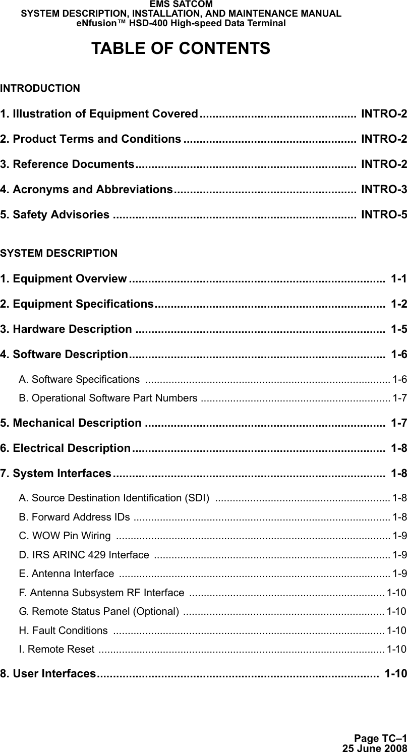

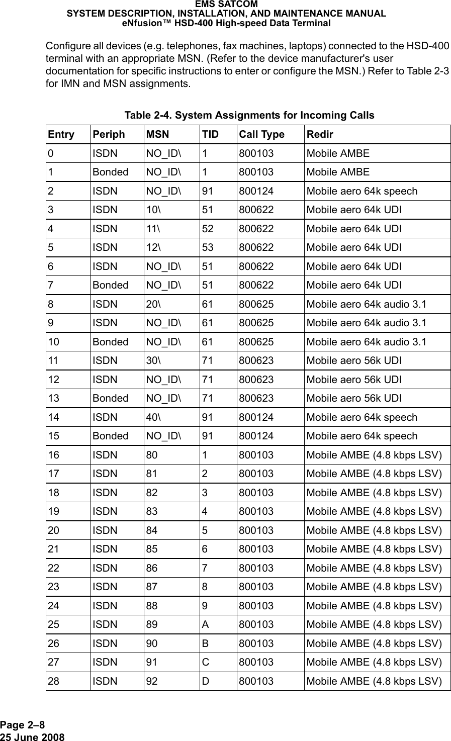
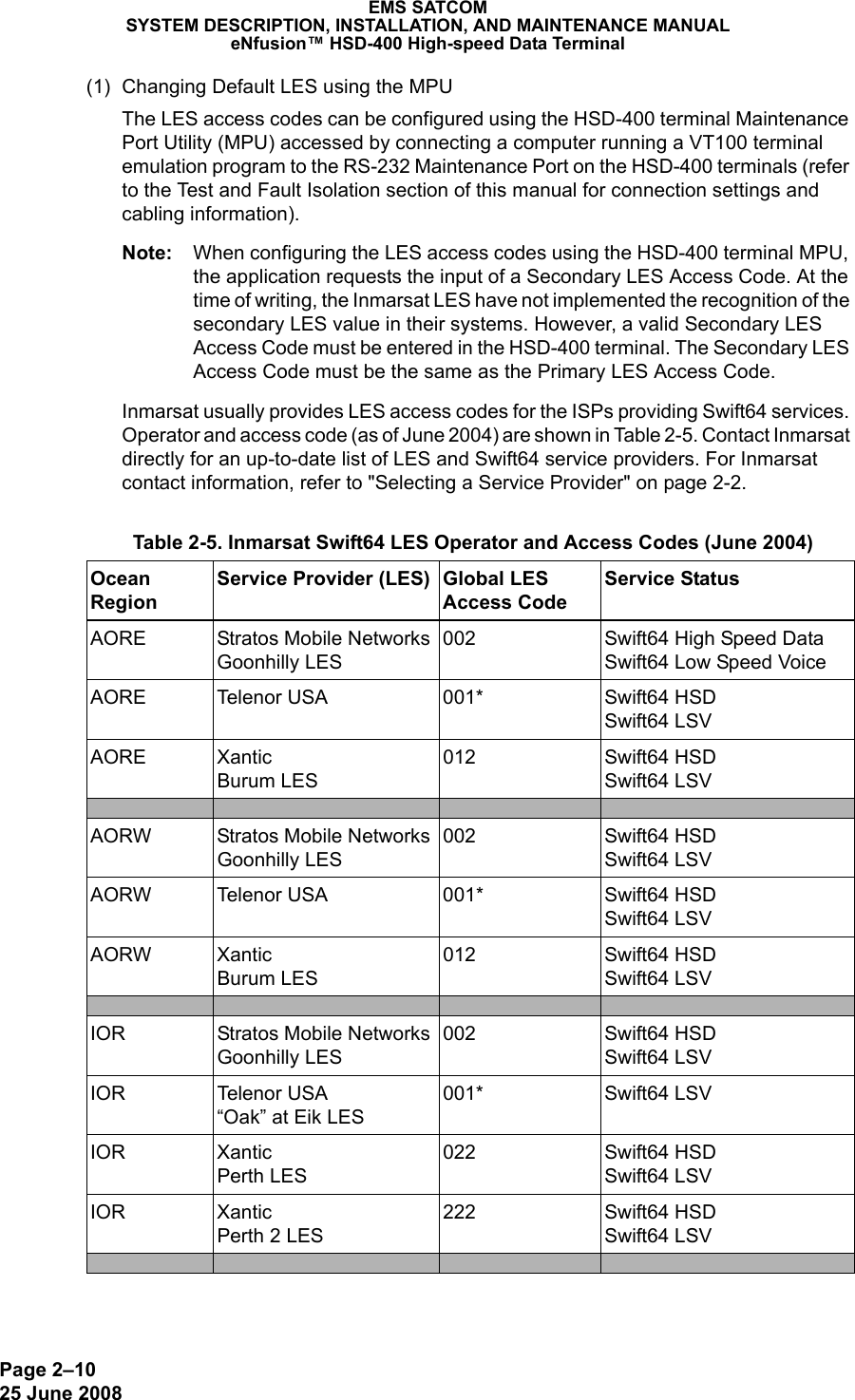
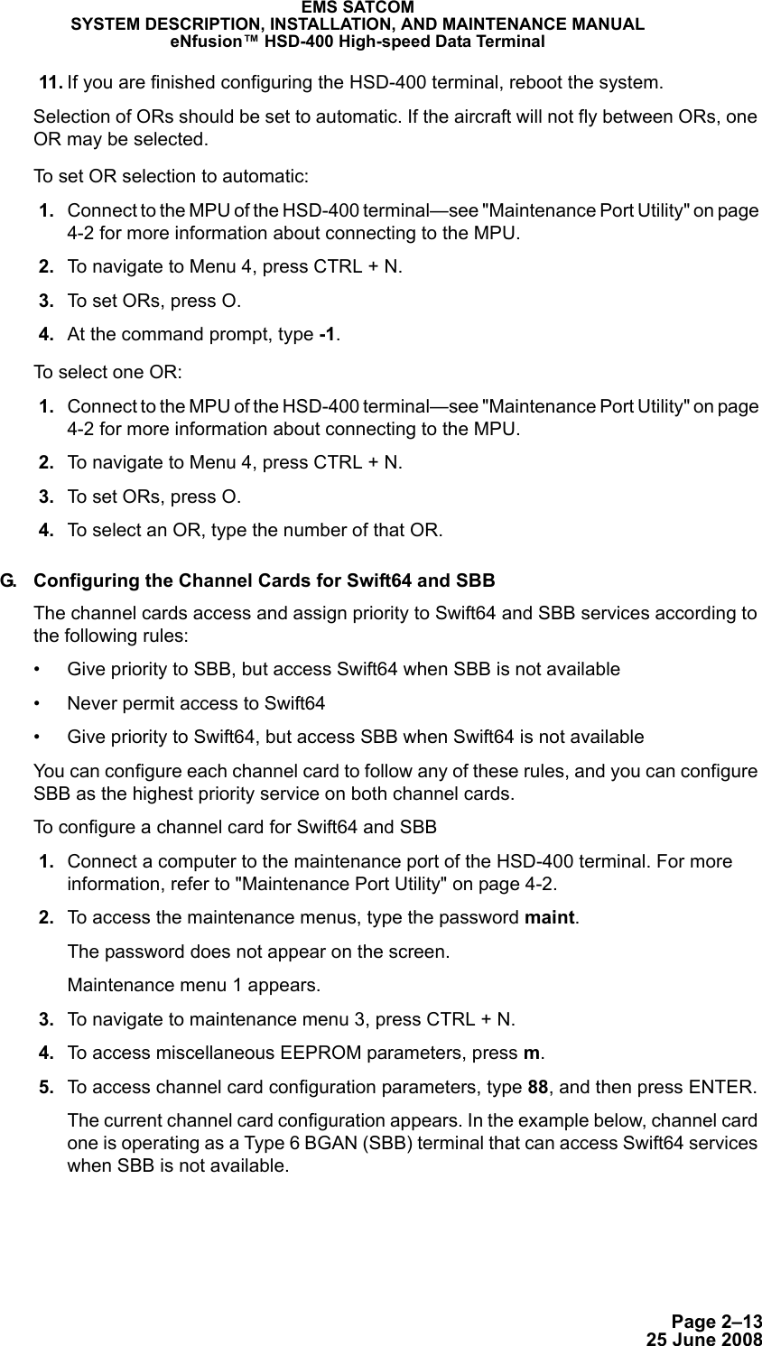
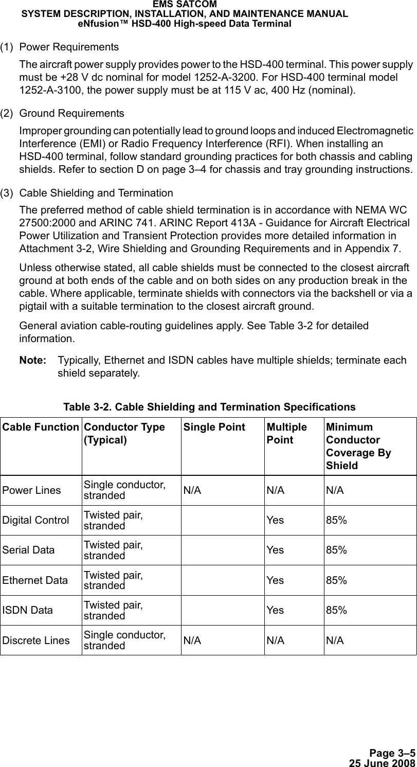
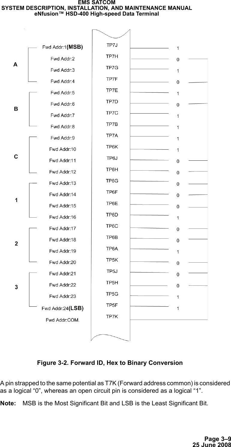
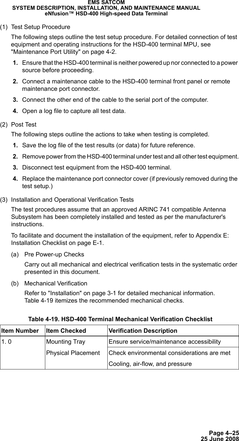
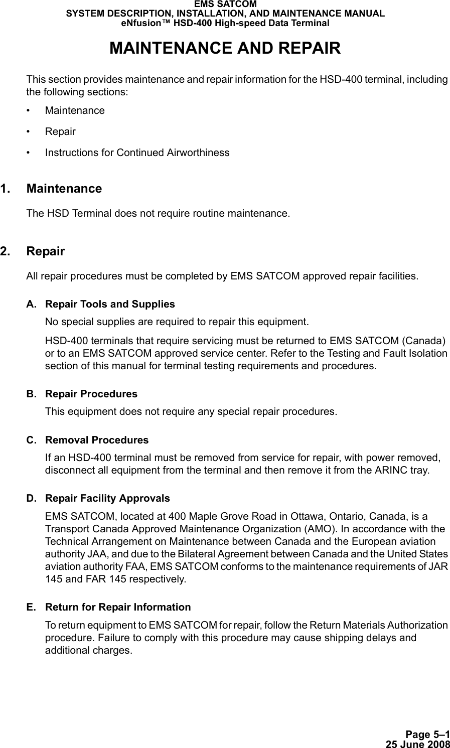
![Page 2–1125 June 2008EMS SATCOMSYSTEM DESCRIPTION, INSTALLATION, AND MAINTENANCE MANUALeNfusion™ HSD-400 High-speed Data Terminal* When using the LES code 001 for Telenor, calls are automatically routed to the appropriate service (either Swift64 LSV or Swift64 HSD, as defined by the OD/ID code of the call). No additional user action is required. Contact Inmarsat for an up-to-date listing of service providers. Contact your service provider for more information on the services they provide.(a) Equipment RequiredThe following equipment is required to change the default LES access code in an HSD-400 terminal: • Computer (Laptop or PC)• Windows 95® or later (Windows 2000® recommended)• HSD-400 terminal control processor software• Terminal emulation program (e.g. HyperTerminal)(b) Connecting to the Maintenance Port Connect a PC or laptop running a terminal emulation program to the HSD-400 terminal maintenance port, and then power up the system. (Refer to "Test and Fault Isolation" on page 4-1of this manual for detailed connection information.)(c) Changing LES access codes on a call-by-call basisNote: You can also change the LES code on a call-by-call basis using the dial code prefix 901 when troubleshooting and diagnosing network problems. The following dial-sequence uses the Xantic POR LES Access Code [022] as an example only. To change the LES access code on a call-by-call basis in all control processor software versions:POR Stratos New Zealand Auckland LES002 Swift64 HSD Swift64 LSVPOR Telenor USA Santa Paula LES001* Swift64 HSD Swift64 LSVPOR Xantic Perth LES022 Swift64 HSD Swift64 LSVPOR Xantic Perth 2 LES012 Swift64 HSD Swift64 LSVPOR Xantic-Netherlands Perth LES022 Swift64 HSD Swift64 LSV901 + LES CODE + International Code + Country Code + Area Code + Telephone Number + #Example: 901 + 022 + 00 + 1+ 613+5551212 + # Table 2-5. Inmarsat Swift64 LES Operator and Access Codes (June 2004) Ocean RegionService Provider (LES) Global LES Access CodeService Status](https://usermanual.wiki/EMS-Technologies-Canada/HSD-400/User-Guide-1264161-Page-53.png)
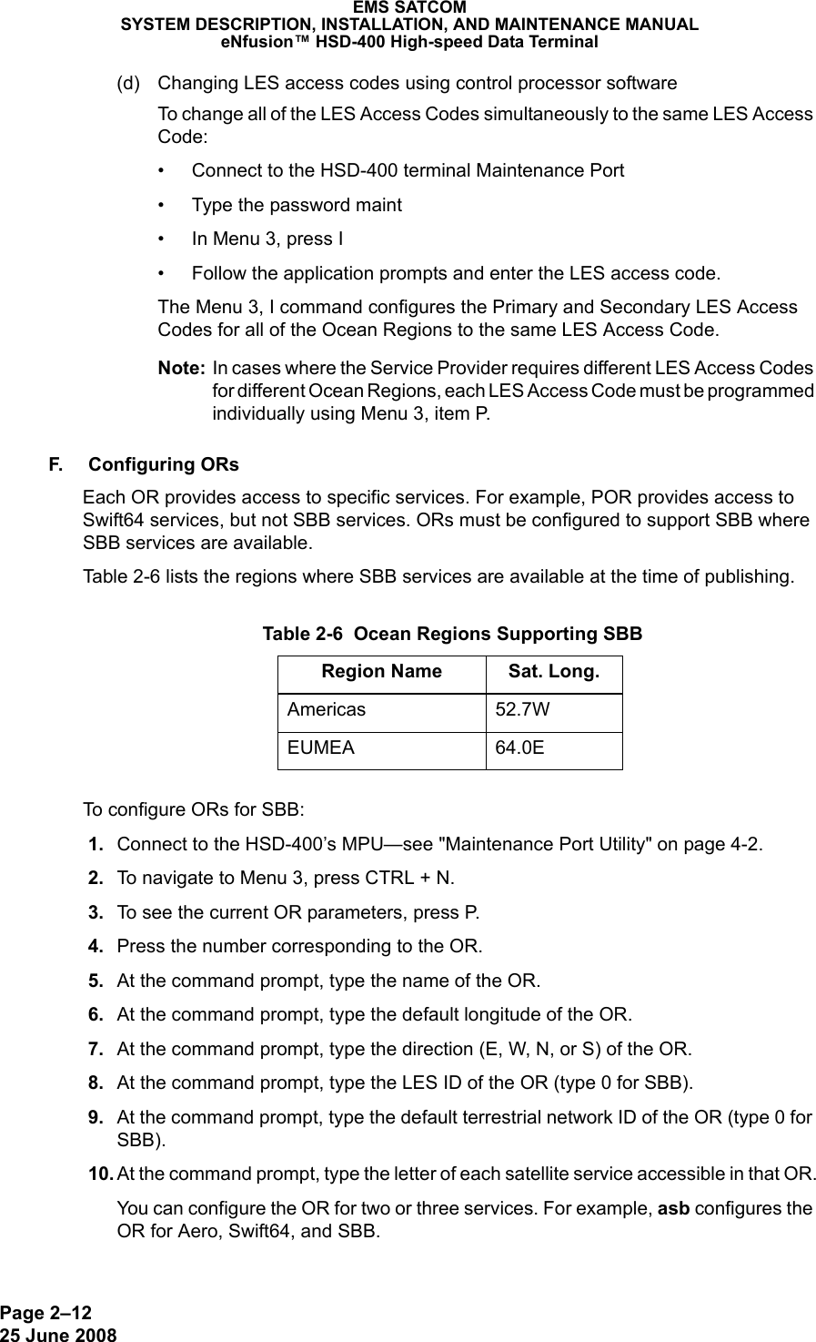
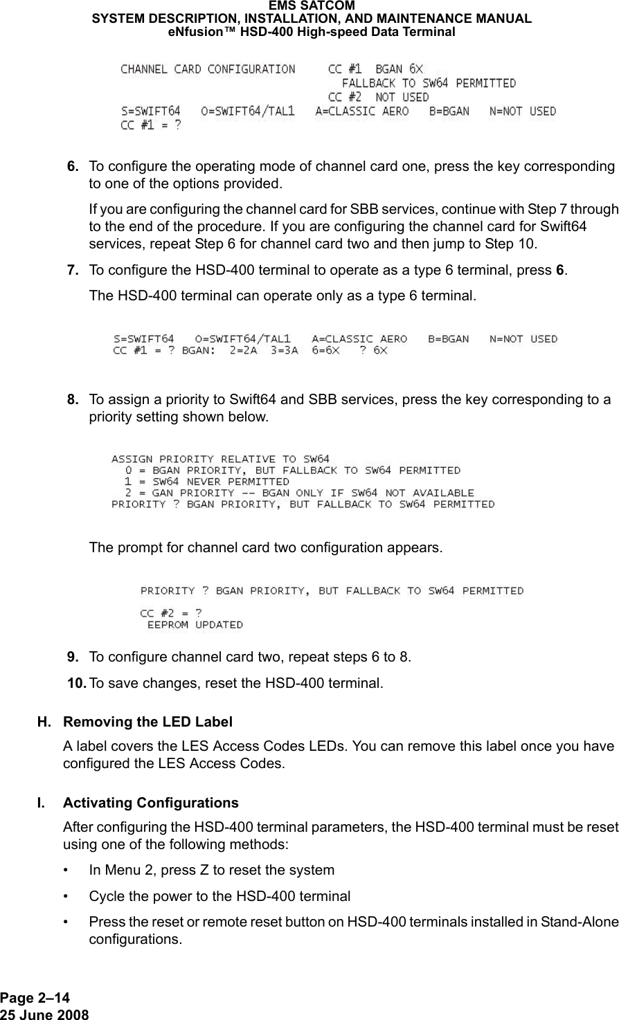
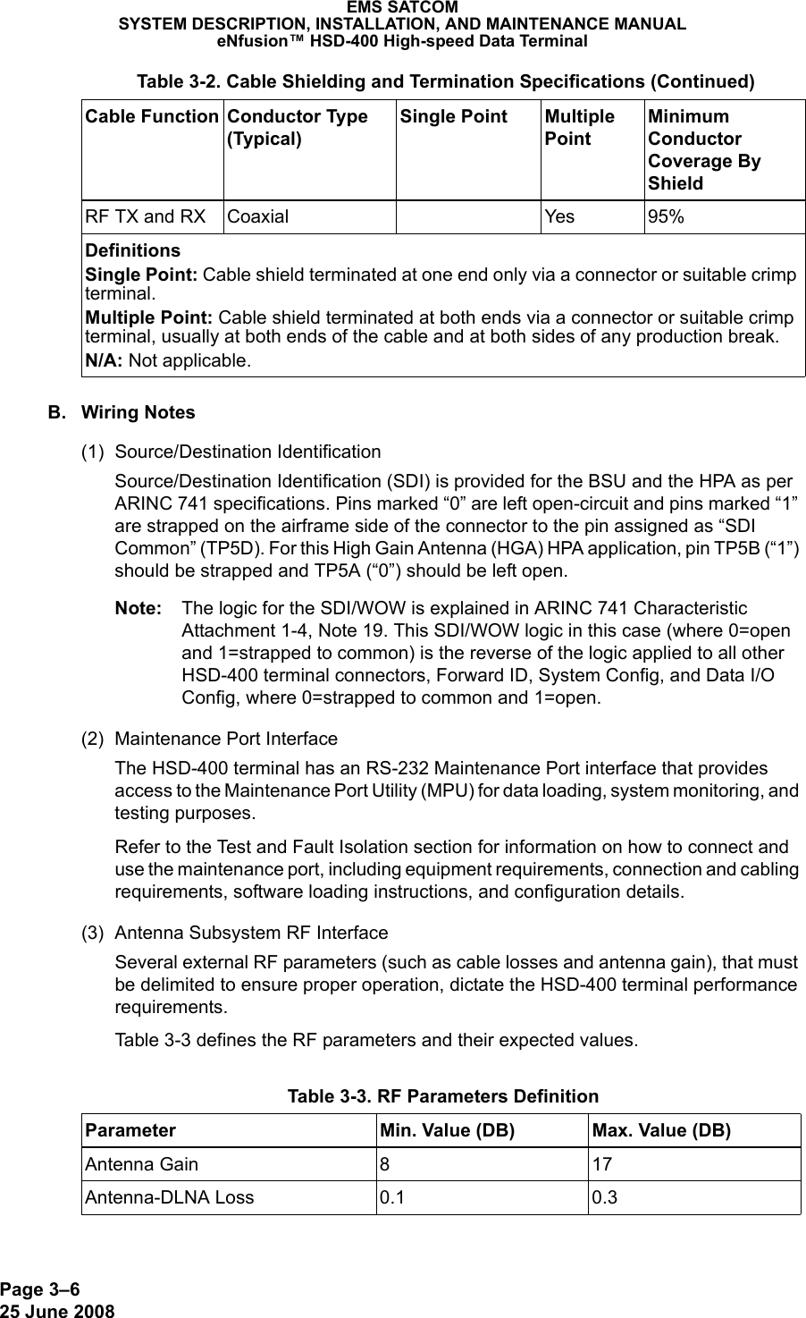
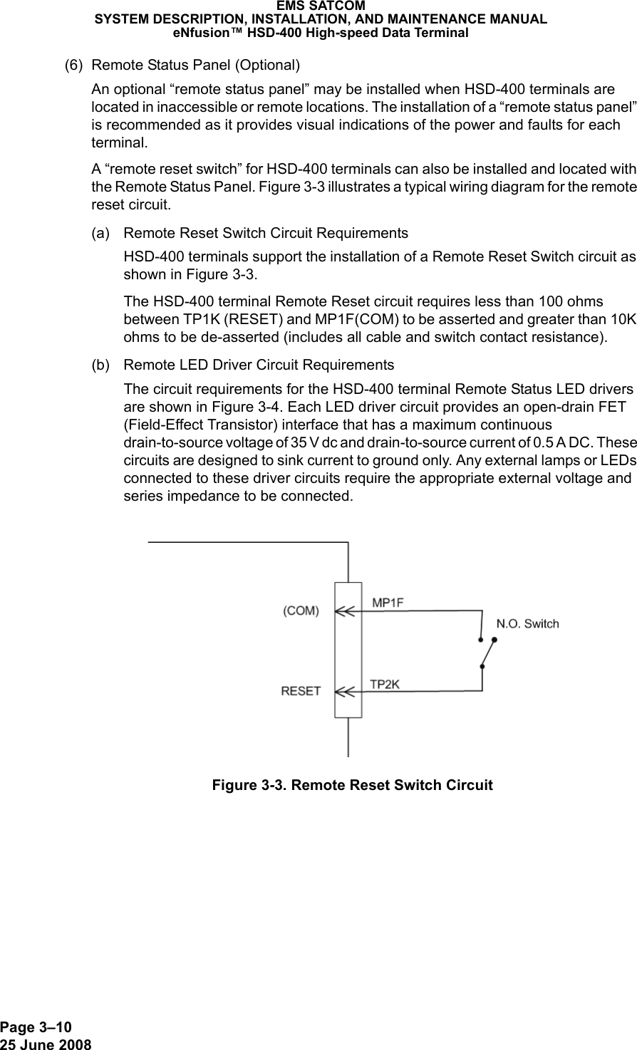


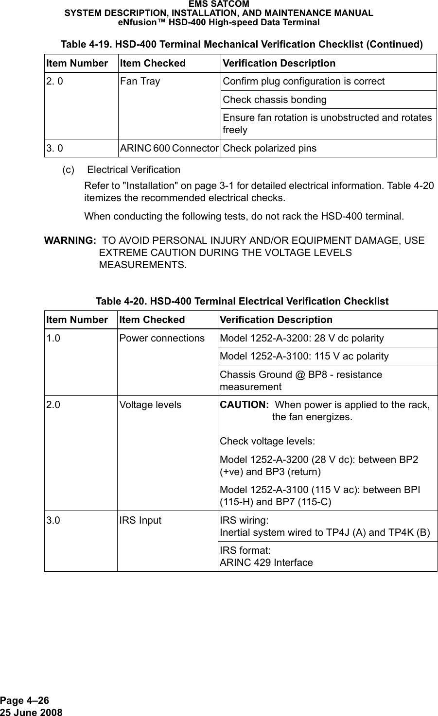
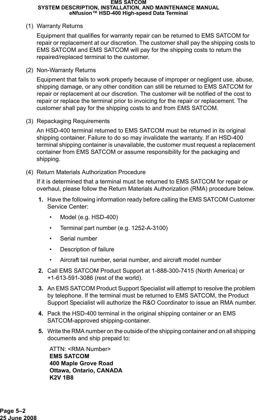
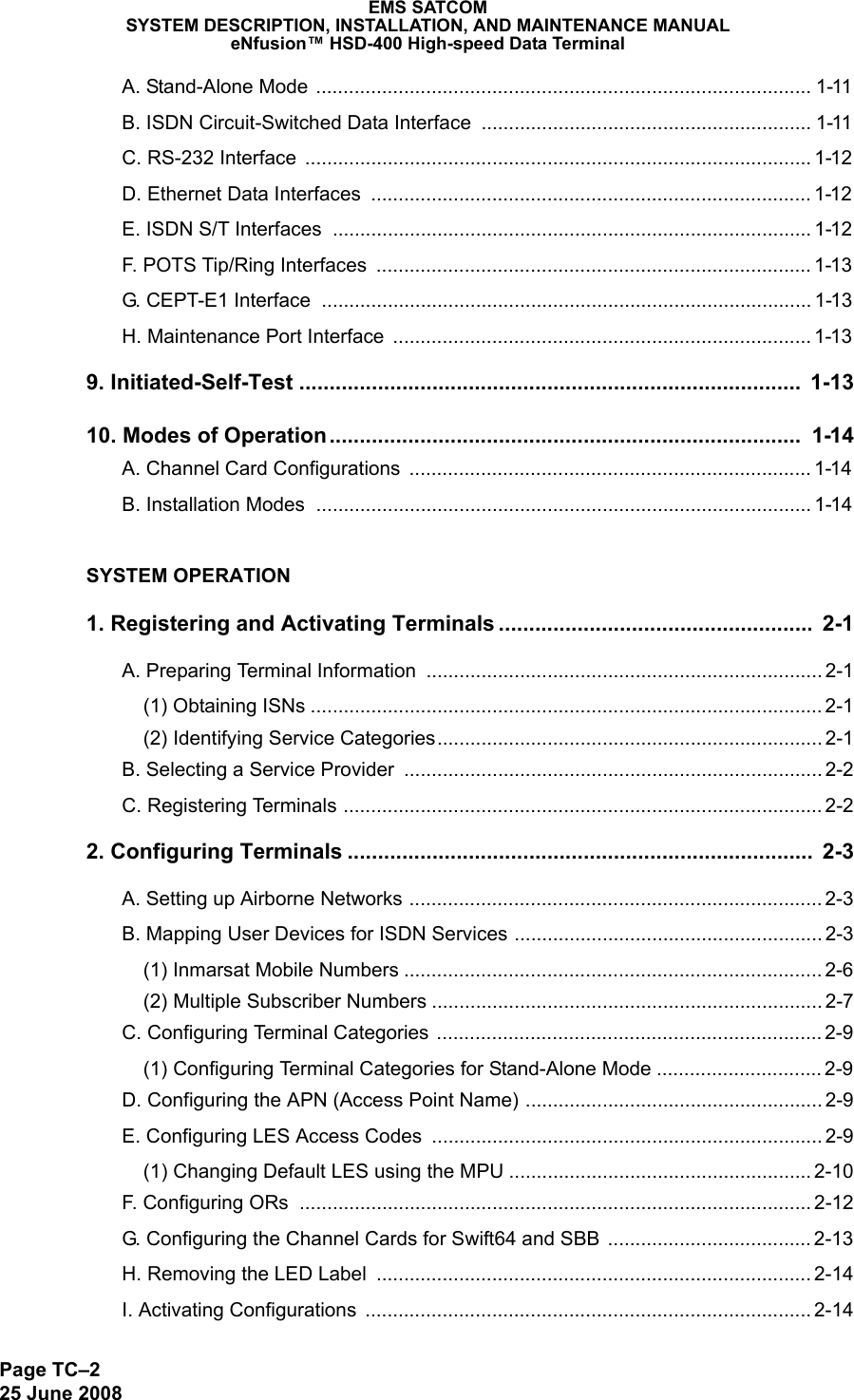
![Page 5–325 June 2008EMS SATCOMSYSTEM DESCRIPTION, INSTALLATION, AND MAINTENANCE MANUALeNfusion™ HSD-400 High-speed Data Terminal 6. Fax or email the details of the shipment to the R&O Coordinator, including the following information: Shipment date, carrier name, and the waybill number.Note: The processing of LRU returns is limited to standard business hours from 8:30 am to 5:00 pm EST. For General inquiries and status requests, please contact the R&O Department directly:Phone: 613-591-9064, extension 1214 (R&O Group)Email: rmareturns@emssatcom.comFax: 613-591-89513. Instructions for Continued AirworthinessThis section presents the instructions for continued airworthiness, as per FAR 25.1529, of the HSD-400 Satellite Terminal. Installation of the HSD-400 terminal on an aircraft by supplemental type certificate (STC) or Form 337 obligates the aircraft operator to include the maintenance information supplied by this manual in the operator's Aircraft Maintenance manual and the operator's Aircraft Scheduled Maintenance Program. The following paragraphs describe all maintenance requirements and instructions for continued airworthiness of the HSD-400 terminal. • Add the LRU part numbers and other necessary part numbers contained in this manual to the aircraft operator's appropriate, aircraft illustrated parts catalog (IPC).• Add all wiring diagram information contained in this manual to the aircraft operator's appropriate aircraft Wiring Diagram Manuals.• HSD-400 terminals are considered on-condition terminals. No additional or routine maintenance is required. • If an HSD-400 terminal is inoperative, remove the terminal, secure cables and wiring, collar applicable switches and circuit breakers, and placard them as “inoperative.” Before flight, revise the equipment list and weight and balance data as applicable and record the removal of the terminal in the log book [refer to section 91.213 of the FAR or the aircraft's minimum equipment list (MEL)]. • HSD-400 terminals are not field-repairable. All terminals must be returned to the EMS SATCOM factory or authorized repair centers for repair.• Repaired terminal must be re-installed on the aircraft in accordance with the instructions provided in this manual. The operation of all repaired terminals must be verified using the operational verification tests and procedures provided in this manual before being approved for return to service. All special tools required to test the terminal for approval for return to service are listed and described in the Test and Fault Isolation section of this manual. Approval for return to service must be entered in the logbook as required by section 43.9 of the FAR.• The following scheduled maintenance tasks must be added to the aircraft operator's appropriate aircraft maintenance program:• Recommended periodic scheduled servicing tasks: None required.• Recommended periodic inspections: None required.](https://usermanual.wiki/EMS-Technologies-Canada/HSD-400/User-Guide-1264161-Page-161.png)