EMS Technologies Canada JETWAVE KA Band Aviation Radio User Manual 23 15 29R001
EMS Technologies Canada, Ltd. KA Band Aviation Radio 23 15 29R001
Contents
- 1. Manual
- 2. Manual part1
- 3. Manual part2
- 4. Manual part3
Manual part1

Honeywell International Inc.
400 Maple Grove Road
Ottawa, Ontario
Canada K2V 1B8
CAGE: 38473
Telephone: (800) 601-3099 (Toll Free U.S.A./Canada)
Telephone: +1-(602) 365-3099 (International Direct)
Website: www.myaerospace.com
Page T-1
Publication Number D201401000049, Revision 1 Initial 16 Jan 2015
Revised 16 Sep 2015
© Honeywell International Inc. Do not copy without express permission of Honeywell.
23-15-29
This document contains technical data and is subject to U.S. export regulations. These commodities,
technology, or software were exported from the United States in accordance with the export administration
regulations. Diversion contrary to U.S. law is prohibited.
ECCN: 7E994
JetWave™ System
System Description and Installation Manual
This guide provides procedures for installation, configuration, and operation of the equipment listed
below.
Model Part Number
JetWave™ System Class A Forced Air KRFU 90401028-001
JetWave™ System Class A Conduction Cooled KRFU, Version 1 90401028-002
JetWave™ System Class A Conduction Cooled KRFU, Version 2 90401028-003
JetWave™ System Class B Forced Air KRFU 90401027-001
JetWave™ System Class B Conduction Cooled KRFU, Version 1 90401027-002
JetWave™ System Class B Conduction Cooled KRFU, Version 2 90401027-003
JetWave™ System Class A Conduction Cooled KRFU, Version 2, FMA 90401027-004
JetWave™ System Class A Forced Air KRFU, Version 2, FMA 90401027-005
A791 Radome Package 90400017-XXX
Non-A791 Radome Package 90400016-XXX
Legal Notice
Export Control

Page T-2
16 Sep 2015
23-15-29
SYSTEM DESCRIPTION AND INSTALLATION MANUAL
JetWave™ System
© Honeywell International Inc. Do not copy without express permission of Honeywell.
Proprietary Information
Honeywell – Confidential
THIS COPYRIGHTED WORK AND ALL INFORMATION ARE THE PROPERTY OF HONEYWELL
INTERNATIONAL INC., CONTAIN TRADE SECRETS AND MAY NOT, IN WHOLE OR IN PART, BE USED,
DUPLICATED, OR DISCLOSED FOR ANY PURPOSE WITHOUT PRIOR WRITTEN PERMISSION OF
HONEYWELL INTERNATIONAL INC. ALL RIGHTS RESERVED.
Honeywell Materials License Agreement
The documents and information contained herein (“the Materials”) are the proprietary data of Honeywell
International Inc. These Materials are provided for the exclusive use of Honeywell Service Centers;
Honeywell-authorized repair facilities; operators of Honeywell aerospace products subject to an applicable
product support agreement, their wholly owned-subsidiaries or a formally designated third party service provider;
and direct recipients of Materials from Honeywell’s Aerospace Technical Publication Distribution. The terms and
conditions of this License Agreement govern your use of these Materials, except to the extent that any terms
and conditions of another applicable agreement with Honeywell regarding the operation, maintenance, or repair
of Honeywell aerospace products conflict with the terms and conditions of this License Agreement, in which
case the terms and conditions of the other agreement will govern. However, this License Agreement will govern
in the event of a conflict between its terms and conditions and those of a purchase order or acknowledgment.
1. License Grant - If you are a party to an applicable product support agreement, a Honeywell Service Center
agreement, or an authorized repair facility agreement, Honeywell hereby grants you a limited, non-exclusive
license to use these Materials to operate, maintain, or repair Honeywell aerospace products only in accordance
with that agreement.
If you are a direct recipient of these Materials from Honeywell’s Aerospace Technical Publication Distribution
and are not a party to an agreement related to the operation, maintenance or repair of Honeywell aerospace
products, Honeywell hereby grants you a limited, non-exclusive license to use these Materials to maintain or
repair the subject Honeywell aerospace products only at the facility to which these Materials have been shipped
("the Licensed Facility"). Transfer of the Materials to another facility owned by you is permitted only if the original
Licensed Facility retains no copies of the Materials and you provide prior written notice to Honeywell.
2. Rights In Materials - Honeywell retains all rights in these Materials and in any copies thereof that are not
expressly granted to you, including all rights in patents, copyrights, trademarks, and trade secrets. No license
to use any Honeywell trademarks or patents is granted under this License Agreement.
3. Confidentiality - You acknowledge that these Materials contain information that is confidential and proprietary
to Honeywell. You agree to take all reasonable efforts to maintain the confidentiality of these Materials.
4. Assignment And Transfer - This License Agreement may be assigned to a formally designated service
designee or transferred to a subsequent owner or operator of an aircraft containing the subject Honeywell
aerospace products. However, the recipient of any such assignment or transfer must assume all of your
obligations under this License Agreement. No assignment or transfer shall relieve any party of any obligation
that such party then has hereunder.
5. Copies of Materials - Unless you have the express written permission of Honeywell, you may not make or
permit making of copies of the Materials. Notwithstanding the foregoing, you may make copies of only portions
of the Material for your internal use. You agree to return the Materials and any copies thereof to Honeywell upon
the request of Honeywell.

Page T-3
16 Sep 2015
23-15-29
SYSTEM DESCRIPTION AND INSTALLATION MANUAL
JetWave™ System
© Honeywell International Inc. Do not copy without express permission of Honeywell.
6. Term - This License Agreement is effective until terminated as set forth herein. This License Agreement will
terminate immediately, without notice from Honeywell, if you fail to comply with any provision of this License
Agreement or will terminate simultaneously with the termination or expiration of your applicable product support
agreement, authorized repair facility agreement, or your formal designation as a third party service provider.
Upon termination of this License Agreement, you will return these Materials to Honeywell without retaining any
copies and will have one of your authorized officers certify that all Materials have been returned with no copies
retained.
7. Remedies - Honeywell reserves the right to pursue all available remedies and damages resulting from a
breach of this License Agreement.
8. Limitation of Liability - Honeywell does not make any representation regarding the use or sufficiency of the
Materials. THERE ARE NO OTHER WARRANTIES, WHETHER WRITTEN OR ORAL, EXPRESS, IMPLIED
OR STATUTORY, INCLUDING, BUT NOT LIMITED TO, (i) WARRANTIES ARISING FROM COURSE OF
PERFORMANCE, DEALING, USAGE, OR TRADE, WHICH ARE HEREBY EXPRESSLY DISCLAIMED, OR (ii)
WARRANTIES AGAINST INFRINGEMENT OF INTELLECTUAL PROPERTY RIGHTS OF THIRD PARTIES,
EVEN IF HONEYWELL HAS BEEN ADVISED OF ANY SUCH INFRINGEMENT. IN NO EVENT WILL
HONEYWELL BE LIABLE FOR ANY INCIDENTAL DAMAGES, CONSEQUENTIAL DAMAGES, SPECIAL
DAMAGES, INDIRECT DAMAGES, LOSS OF PROFITS, LOSS OF REVENUES, OR LOSS OF USE, EVEN IF
INFORMED OF THE POSSIBILITY OF SUCH DAMAGES. TO THE EXTENT PERMITTED BY APPLICABLE
LAW, THESE LIMITATIONS AND EXCLUSIONS WILL APPLY REGARDLESS OF WHETHER LIABILITY
ARISES FROM BREACH OF CONTRACT, WARRANTY, TORT (INCLUDING BUT NOT LIMITED TO
NEGLIGENCE), BY OPERATION OF LAW, OR OTHERWISE.
9. Controlling Law - This License shall be governed and construed in accordance with the laws of the State of
New York without regard to the conflicts of laws provisions thereof. This license sets forth the entire agreement
between you and Honeywell and may only be modified by a writing duly executed by the duly authorized
representatives of the parties.
Safety Advisory
WARNING: BEFORE THE MATERIALS CALLED OUT IN THIS PUBLICATION ARE USED, KNOW THE
HANDLING, STORAGE AND DISPOSAL PRECAUTIONS RECOMMENDED BY THE MANUFACTURER OR
SUPPLIER. FAILURE TO OBEY THE MANUFACTURERS’ OR SUPPLIERS’ RECOMMENDATIONS CAN
RESULT IN PERSONAL INJURY OR DISEASE.
This publication describes physical and chemical processes which can make it necessary to use chemicals,
solvents, paints, and other commercially available materials. The user of this publication must get the Material
Safety Data Sheets (OSHA Form 174 or equivalent) from the manufacturers or suppliers of the materials to be
used. The user must know the manufacturer/supplier data and obey the procedures, recommendations, warnings
and cautions set forth for the safe use, handling, storage, and disposal of the materials.
Warranty/Liability Advisory
WARNING: HONEYWELL ASSUMES NO RESPONSIBILITY FOR ANY HONEYWELL EQUIPMENT WHICH
IS NOT MAINTAINED AND/OR REPAIRED IN ACCORDANCE WITH HONEYWELL’S PUBLISHED
INSTRUCTIONS AND/OR HONEYWELL’S FAA/SFAR 36 REPAIR AUTHORIZATION. NEITHER DOES
HONEYWELL ASSUME RESPONSIBILITY FOR SPECIAL TOOLS AND TEST EQUIPMENT FABRICATED BY
COMPANIES OTHER THAN HONEYWELL.
WARNING: INCORRECTLY REPAIRED COMPONENTS CAN AFFECT AIRWORTHINESS OR DECREASE
THE LIFE OF THE COMPONENTS. INCORRECTLY FABRICATED SPECIAL TOOLING OR TEST
EQUIPMENT CAN RESULT IN DAMAGE TO THE PRODUCT COMPONENTS OR GIVE UNSATISFACTORY
RESULTS.

Page T-4
16 Sep 2015
23-15-29
SYSTEM DESCRIPTION AND INSTALLATION MANUAL
JetWave™ System
© Honeywell International Inc. Do not copy without express permission of Honeywell.
Copyright - Notice
Copyright 2015 Honeywell International Inc. All rights reserved.
Honeywell is a registered trademark of Honeywell International Inc.
All other marks are owned by their respective companies.
JetWave™ System, System Description, Installation, and Maintenance Manual
Document Number: D201401000049, Revision 1
16 Sep 2015
Our products are under continuous research and development. Any information may therefore be changed
without prior notice. Honeywell reserves the right to make improvements or changes in the product described
in this manual at any time without notice. While reasonable efforts have been made in the preparation of this
document to assure its accuracy, Honeywell assumes no liability resulting from any errors or omissions in this
document, or from the use of the information contained herein.
Honeywell International Inc.
400 Maple Grove Road
Ottawa, Ontario, K2V 1B8
Canada
Reception: 613-591-9064
Product Support: Aerospace Technical Support
1-855-808-6500 (U.S. and Canada) or +1-602-365-6500 (International)
E-mail: AeroTechSupport@Honeywell.com

Page TI-1
16 Sep 2015
23-15-29
SYSTEM DESCRIPTION AND INSTALLATION MANUAL
JetWave™ System
© Honeywell International Inc. Do not copy without express permission of Honeywell.
TRANSMITTAL INFORMATION
TO THE HOLDERS OF JETWAVE™ SYSTEM SDIM, ATA NO. 23-15-29 (PUB. NO. D201401000049), ISSUED
FOR USE IN SUPPORT OF THE FOLLOWING:
Table TI-1 shows the applicable components.
Revision History
Table TI-2 shows the revision history of this SDIM.
This revision is a full replacement. All changed pages have a new date. Revision bars identify the changed data.
Remove and discard all pages of the manual and replace them with the attached pages. Write the revision
number, revision date, and replacement date on the Record of Revisions page.
The table of highlights tells users what has changed as a result of the revision. The table consists of three
columns.
Table TI-1. Applicable Components
Component PN Nomenclature
90401028-001 JetWave™ System Class A Forced Air KRFU
90401028-002 JetWave™ System Class A Conduction Cooled KRFU, Version 1
90401028-003 JetWave™ System Class A Conduction Cooled KRFU, Version 2
90401027-001 JetWave™ System Class B Forced Air KRFU
90401027-002 JetWave™ System Class B Conduction Cooled KRFU, Version 1
90401027-003 JetWave™ System Class B Conduction Cooled KRFU, Version 2
90401027-004 JetWave™ System Class A Conduction Cooled KRFU, Version 2, FMA
90401027-005 JetWave™ System Class A Forced Air KRFU, Version 2, FMA
90400017-XXX A791 Radome Package
90400016-XXX Non-A791 Radome Package
Table TI-2. Revision History
Revision Revision Date
0 16 Jan 2015
1 16 Sep 2015

Page TI-2
16 Sep 2015
23-15-29
SYSTEM DESCRIPTION AND INSTALLATION MANUAL
JetWave™ System
© Honeywell International Inc. Do not copy without express permission of Honeywell.
The Task/Page column identifies the blocks of changed information, such as a task, subtask, graphic, or parts
list, and the page on which that block starts. Revision marks, when provided, identify the location of the change
within the block.
The Description of Change column tells about the change or changes within each block. The description of
change is often preceded by a paragraph or figure reference that applies to the block of information.
The Effectivity column tells the user the part number(s) to which the block of information applies. The default
value for this column is “All.” “All” means that the block applies to all parts.
Table of Highlights
Page Description of Change Effectivity
All Global Change: The editorial changes and data that were
moved or reformatted are not identified with revision bars. All
All Global Change: Some paragraphs, tables, and figures have
been renumbered and are not identified with revision bars.
All
All Global Change: Added Component PNs 90401027-004 and
90401027-005. All
All Due to the extent and complexity of changes made in this
revision, individual changes are not detailedDQGUHYLVLRQEDUV
DUHQRWXVHG.
All

Page RR-1
16 Sep 2015
23-15-29
SYSTEM DESCRIPTION AND INSTALLATION MANUAL
JetWave™ System
© Honeywell International Inc. Do not copy without express permission of Honeywell.
RECORD OF REVISIONS
When revisions are received, insert revised pages, record the date, and initial.
Revision Number Issue Date Date Inserted Inserted by (initial)

Page RR-2
16 Sep 2015
23-15-29
SYSTEM DESCRIPTION AND INSTALLATION MANUAL
JetWave™ System
© Honeywell International Inc. Do not copy without express permission of Honeywell.
Blank Page

Page RTR-1
16 Sep 2015
23-15-29
SYSTEM DESCRIPTION AND INSTALLATION MANUAL
JetWave™ System
© Honeywell International Inc. Do not copy without express permission of Honeywell.
RECORD OF TEMPORARY REVISIONS
Instructions on each page of a temporary revision tell you where to put the pages in your manual. Remove
temporary revision pages only when discard instructions are given. For each temporary revision, put the
applicable data in the record columns on this page.
Definition of Status column: TR may be active, incorporated, or deleted. “Active” is entered by the holder of
manual. “Incorporated” means a TR has been incorporated into the manual and includes the revision number
of the manual when the TR was incorporated. “Deleted” means a TR has been replaced by another TR, a TR
number will not be issued, or a TR has been deleted.
Temporary
Revision
Number Status Page
Number Issue
Date Date Put in
Manual By
Date
Removed
From Manual By

Page RTR-2
16 Sep 2015
23-15-29
SYSTEM DESCRIPTION AND INSTALLATION MANUAL
JetWave™ System
© Honeywell International Inc. Do not copy without express permission of Honeywell.
Blank Page

Page SBL-1
16 Sep 2015
23-15-29
SYSTEM DESCRIPTION AND INSTALLATION MANUAL
JetWave™ System
© Honeywell International Inc. Do not copy without express permission of Honeywell.
SERVICE BULLETIN LIST
Service Bulletin
Number Subject Manual Rev.
Number Manual Rev.
Date

Page SBL-2
16 Sep 2015
23-15-29
SYSTEM DESCRIPTION AND INSTALLATION MANUAL
JetWave™ System
© Honeywell International Inc. Do not copy without express permission of Honeywell.
Blank Page

Page LEP-1
16 Sep 2015
23-15-29
SYSTEM DESCRIPTION AND INSTALLATION MANUAL
JetWave™ System
© Honeywell International Inc. Do not copy without express permission of Honeywell.
Subheading and Page Date Subheading and Page Date
* indicates a changed or added page.
F indicates a foldout page.
Title
T-1 *16 Sep 2015
T-2 16 Sep 2015
T-3 16 Sep 2015
T-4 *16 Sep 2015
Transmittal Information
TI-1 *16 Sep 2015
TI-2 *16 Sep 2015
TI-3 *16 Sep 2015
TI-4 *16 Sep 2015
TI-5 *16 Sep 2015
TI-6 *16 Sep 2015
TI-7 *16 Sep 2015
TI-8 *16 Sep 2015
TI-9 *16 Sep 2015
TI-10 *16 Sep 2015
Record of Revisions
RR-1 16 Sep 2015
RR-2 16 Sep 2015
Record of Temporary Revisions
RTR-1 16 Sep 2015
RTR-2 16 Sep 2015
Service Bulletin List
SBL-1 16 Sep 2015
SBL-2 16 Sep 2015
List of Effective Pages
LEP-1 *16 Sep 2015
LEP-2 *16 Sep 2015
LEP-3 *16 Sep 2015
LEP-4 *16 Sep 2015
LEP-5 *16 Sep 2015
LEP-6 *16 Sep 2015
Table of Contents
TC-1 *16 Sep 2015
TC-2 *16 Sep 2015
TC-3 *16 Sep 2015
TC-4 *16 Sep 2015
TC-5 *16 Sep 2015
TC-6 *16 Sep 2015
TC-7 *16 Sep 2015
TC-8 *16 Sep 2015
TC-9 *16 Sep 2015
TC-10 *16 Sep 2015
Introduction
INTRO-1 16 Sep 2015
INTRO-2 *16 Sep 2015
INTRO-3 *16 Sep 2015
INTRO-4 *16 Sep 2015
INTRO-5 16 Sep 2015
INTRO-6 16 Sep 2015
INTRO-7 16 Sep 2015
INTRO-8 16 Sep 2015
Description and Operation
1-1 *16 Sep 2015
1-2 *16 Sep 2015
1-3 *16 Sep 2015
1-4 *16 Sep 2015
1-5 *16 Sep 2015
1-6 *16 Sep 2015
1-7 *16 Sep 2015
1-8 *16 Sep 2015
1-9 *16 Sep 2015
1-10 *16 Sep 2015
1-11 *16 Sep 2015
1-12 *16 Sep 2015
1-13 *16 Sep 2015
1-14 16 Sep 2015
Installation
2-1 *16 Sep 2015
2-2 *16 Sep 2015
2-3 *16 Sep 2015
2-4 *16 Sep 2015
2-5 *16 Sep 2015
2-6 *16 Sep 2015
2-7 *16 Sep 2015
2-8 *16 Sep 2015
2-9 *16 Sep 2015
2-10 *16 Sep 2015
2-11 *16 Sep 2015
2-12 *16 Sep 2015
2-13 *16 Sep 2015
2-14 *16 Sep 2015
2-15 *16 Sep 2015
2-16 *16 Sep 2015
2-17 *16 Sep 2015
2-18 *16 Sep 2015
2-19 *16 Sep 2015
2-20 *16 Sep 2015
2-21 *16 Sep 2015
2-22 *16 Sep 2015
2-23 *16 Sep 2015
2-24 *16 Sep 2015

Page LEP-2
16 Sep 2015
23-15-29
SYSTEM DESCRIPTION AND INSTALLATION MANUAL
JetWave™ System
© Honeywell International Inc. Do not copy without express permission of Honeywell.
Subheading and Page Date Subheading and Page Date
* indicates a changed or added page.
F indicates a foldout page.
2-25 *16 Sep 2015
2-26 *16 Sep 2015
2-27 *16 Sep 2015
2-28 *16 Sep 2015
2-29 *16 Sep 2015
2-30 *16 Sep 2015
2-31 *16 Sep 2015
2-32 *16 Sep 2015
2-33 *16 Sep 2015
2-34 *16 Sep 2015
2-35 *16 Sep 2015
2-36 *16 Sep 2015
2-37 *16 Sep 2015
2-38 *16 Sep 2015
2-39 *16 Sep 2015
2-40 *16 Sep 2015
F 2-41 *16 Sep 2015
F 2-42 16 Sep 2015
F 2-43 *16 Sep 2015
F 2-44 16 Sep 2015
F 2-45 *16 Sep 2015
F 2-46 16 Sep 2015
F 2-47 *16 Sep 2015
F 2-48 16 Sep 2015
F 2-49 *16 Sep 2015
F 2-50 16 Sep 2015
F 2-51 *16 Sep 2015
F 2-52 16 Sep 2015
F 2-53 *16 Sep 2015
F 2-54 16 Sep 2015
F 2-55 *16 Sep 2015
F 2-56 16 Sep 2015
F 2-57 *16 Sep 2015
F 2-58 16 Sep 2015
F 2-59 *16 Sep 2015
F 2-60 16 Sep 2015
F 2-61 *16 Sep 2015
F 2-62 16 Sep 2015
F 2-63 *16 Sep 2015
F 2-64 16 Sep 2015
F 2-65 *16 Sep 2015
F 2-66 16 Sep 2015
F 2-67 *16 Sep 2015
F 2-68 16 Sep 2015
F 2-69 *16 Sep 2015
F 2-70 16 Sep 2015
F 2-71 *16 Sep 2015
F 2-72 16 Sep 2015
F 2-73 *16 Sep 2015
F 2-74 16 Sep 2015
F 2-75 *16 Sep 2015
F 2-76 16 Sep 2015
F 2-77 *16 Sep 2015
F 2-78 16 Sep 2015
F 2-79 16 Sep 2015
F 2-80 16 Sep 2015
F 2-81 16 Sep 2015
F 2-82 16 Sep 2015
F 2-83 16 Sep 2015
F 2-84 16 Sep 2015
F 2-85 *16 Sep 2015
F 2-86 16 Sep 2015
F 2-87 *16 Sep 2015
F 2-88 16 Sep 2015
F 2-89 *16 Sep 2015
F 2-90 16 Sep 2015
F 2-91 *16 Sep 2015
F 2-92 16 Sep 2015
F 2-93 *16 Sep 2015
F 2-94 16 Sep 2015
F 2-95 *16 Sep 2015
F 2-96 16 Sep 2015
F 2-97 *16 Sep 2015
F 2-98 16 Sep 2015
F 2-99 *16 Sep 2015
F 2-100 16 Sep 2015
F 2-101 *16 Sep 2015
F 2-102 16 Sep 2015
F 2-103 *16 Sep 2015
F 2-104 16 Sep 2015
F 2-105 *16 Sep 2015
F 2-106 16 Sep 2015
F 2-107 *16 Sep 2015
F 2-108 16 Sep 2015
F 2-109 *16 Sep 2015
F 2-110 16 Sep 2015
F 2-111 *16 Sep 2015
F 2-112 16 Sep 2015
F 2-113 *16 Sep 2015
F 2-114 16 Sep 2015
F 2-115 *16 Sep 2015
F 2-116 16 Sep 2015
F 2-117 *16 Sep 2015
F 2-118 16 Sep 2015
F 2-119 *16 Sep 2015
F 2-120 16 Sep 2015

Page LEP-3
16 Sep 2015
23-15-29
SYSTEM DESCRIPTION AND INSTALLATION MANUAL
JetWave™ System
© Honeywell International Inc. Do not copy without express permission of Honeywell.
Subheading and Page Date Subheading and Page Date
* indicates a changed or added page.
F indicates a foldout page.
F 2-121 *16 Sep 2015
F 2-122 16 Sep 2015
F 2-123 *16 Sep 2015
F 2-124 16 Sep 2015
F 2-125 *16 Sep 2015
F 2-126 16 Sep 2015
F 2-127 *16 Sep 2015
F 2-128 16 Sep 2015
F 2-129 *16 Sep 2015
F 2-130 16 Sep 2015
F 2-131 *16 Sep 2015
F 2-132 16 Sep 2015
F 2-133 *16 Sep 2015
F 2-134 16 Sep 2015
F 2-135 *16 Sep 2015
F 2-136 16 Sep 2015
F 2-137 *16 Sep 2015
F 2-138 16 Sep 2015
F 2-139 *16 Sep 2015
F 2-140 16 Sep 2015
F 2-141 *16 Sep 2015
F 2-142 16 Sep 2015
F 2-143 *16 Sep 2015
F 2-144 16 Sep 2015
F 2-145 16 Sep 2015
F 2-146 16 Sep 2015
F 2-147 16 Sep 2015
F 2-148 16 Sep 2015
F 2-149 16 Sep 2015
F 2-150 16 Sep 2015
F 2-151 16 Sep 2015
F 2-152 16 Sep 2015
F 2-153 16 Sep 2015
F 2-154 16 Sep 2015
F 2-155 16 Sep 2015
F 2-156 16 Sep 2015
F 2-157 16 Sep 2015
F 2-158 16 Sep 2015
F 2-159 16 Sep 2015
F 2-160 16 Sep 2015
F 2-161 *16 Sep 2015
F 2-162 16 Sep 2015
F 2-163 *16 Sep 2015
F 2-164 16 Sep 2015
F 2-165 *16 Sep 2015
F 2-166 16 Sep 2015
F 2-167 *16 Sep 2015
F 2-168 16 Sep 2015
F 2-169 *16 Sep 2015
F 2-170 16 Sep 2015
F 2-171 *16 Sep 2015
F 2-172 16 Sep 2015
F 2-173 *16 Sep 2015
F 2-174 16 Sep 2015
F 2-175 *16 Sep 2015
F 2-176 16 Sep 2015
F 2-177 *16 Sep 2015
F 2-178 16 Sep 2015
F 2-179 *16 Sep 2015
F 2-180 16 Sep 2015
F 2-181 *16 Sep 2015
F 2-182 16 Sep 2015
F 2-183 *16 Sep 2015
F 2-184 16 Sep 2015
F 2-185 *16 Sep 2015
F 2-186 16 Sep 2015
F 2-187 *16 Sep 2015
F 2-188 16 Sep 2015
F 2-189 *16 Sep 2015
F 2-190 16 Sep 2015
F 2-191 *16 Sep 2015
F 2-192 16 Sep 2015
2-193 *16 Sep 2015
2-194 *16 Sep 2015
2-195 *16 Sep 2015
2-196 *16 Sep 2015
2-197 *16 Sep 2015
2-198 *16 Sep 2015
2-199 *16 Sep 2015
2-200 *16 Sep 2015
2-201 *16 Sep 2015
2-202 *16 Sep 2015
2-203 *16 Sep 2015
2-204 *16 Sep 2015
2-205 *16 Sep 2015
2-206 *16 Sep 2015
2-207 *16 Sep 2015
2-208 16 Sep 2015
JetWave AES System Configuration
3-1 *16 Sep 2015
3-2 *16 Sep 2015
3-3 *16 Sep 2015
3-4 *16 Sep 2015
3-5 *16 Sep 2015

Page LEP-4
16 Sep 2015
23-15-29
SYSTEM DESCRIPTION AND INSTALLATION MANUAL
JetWave™ System
© Honeywell International Inc. Do not copy without express permission of Honeywell.
Subheading and Page Date Subheading and Page Date
* indicates a changed or added page.
F indicates a foldout page.
3-6 *16 Sep 2015
3-7 *16 Sep 2015
3-8 *16 Sep 2015
3-9 *16 Sep 2015
3-10 *16 Sep 2015
3-11 *16 Sep 2015
3-12 *16 Sep 2015
3-13 *16 Sep 2015
3-14 *16 Sep 2015
3-15 *16 Sep 2015
3-16 *16 Sep 2015
3-17 *16 Sep 2015
3-18 *16 Sep 2015
3-19 *16 Sep 2015
3-20 *16 Sep 2015
3-21 *16 Sep 2015
3-22 *16 Sep 2015
3-23 *16 Sep 2015
3-24 *16 Sep 2015
3-25 *16 Sep 2015
3-26 *16 Sep 2015
3-27 *16 Sep 2015
3-28 16 Sep 2015
3-29 16 Sep 2015
3-30 *16 Sep 2015
3-31 *16 Sep 2015
3-32 *16 Sep 2015
3-33 *16 Sep 2015
3-34 *16 Sep 2015
3-35 *16 Sep 2015
3-36 *16 Sep 2015
3-37 *16 Sep 2015
3-38 *16 Sep 2015
3-39 *16 Sep 2015
3-40 *16 Sep 2015
3-41 *16 Sep 2015
3-42 *16 Sep 2015
3-43 *16 Sep 2015
3-44 *16 Sep 2015
3-45 *16 Sep 2015
3-46 *16 Sep 2015
3-47 *16 Sep 2015
3-48 *16 Sep 2015
3-49 *16 Sep 2015
3-50 *16 Sep 2015
3-51 *16 Sep 2015
3-52 *16 Sep 2015
3-53 *16 Sep 2015
3-54 *16 Sep 2015
3-55 16 Sep 2015
3-56 *16 Sep 2015
3-57 16 Sep 2015
3-58 16 Sep 2015
3-59 16 Sep 2015
3-60 *16 Sep 2015
3-61 *16 Sep 2015
3-62 *16 Sep 2015
3-63 *16 Sep 2015
3-64 16 Sep 2015
3-65 *16 Sep 2015
3-66 *16 Sep 2015
3-67 *16 Sep 2015
3-68 *16 Sep 2015
3-69 16 Sep 2015
3-70 *16 Sep 2015
3-71 *16 Sep 2015
3-72 *16 Sep 2015
3-72 16 Sep 2015
3-74 16 Sep 2015
3-75 16 Sep 2015
3-76 *16 Sep 2015
3-77 *16 Sep 2015
3-78 *16 Sep 2015
3-79 16 Sep 2015
3-80 *16 Sep 2015
3-81 *16 Sep 2015
3-82 *16 Sep 2015
3-83 *16 Sep 2015
3-84 *16 Sep 2015
3-85 *16 Sep 2015
3-86 16 Sep 2015
3-87 16 Sep 2015
3-88 16 Sep 2015
3-89 16 Sep 2015
3-90 16 Sep 2015
Appendix A: Specifications
A-1 *16 Sep 2015
A-2 *16 Sep 2015
A-3 *16 Sep 2015
A-4 *16 Sep 2015
A-5 *16 Sep 2015
A-6 *16 Sep 2015
A-7 *16 Sep 2015
A-8 *16 Sep 2015
A-9 16 Sep 2015

Page LEP-5
16 Sep 2015
23-15-29
SYSTEM DESCRIPTION AND INSTALLATION MANUAL
JetWave™ System
© Honeywell International Inc. Do not copy without express permission of Honeywell.
Subheading and Page Date Subheading and Page Date
* indicates a changed or added page.
F indicates a foldout page.
A-10 *16 Sep 2015
A-11 *16 Sep 2015
A-12 16 Sep 2015
Appendix B: MIB / SNMP
B-1 *16 Sep 2015
B-2 *16 Sep 2015
B-3 *16 Sep 2015
B-4 *16 Sep 2015
B-5 *16 Sep 2015
B-6 *16 Sep 2015
B-7 *16 Sep 2015
B-8 *16 Sep 2015
B-9 *16 Sep 2015
B-10 *16 Sep 2015
B-11 *16 Sep 2015
B-12 *16 Sep 2015
B-13 *16 Sep 2015
B-14 *16 Sep 2015
Appendix C: Installation Information Sheet
C-1 *16 Sep 2015
C-2 *16 Sep 2015
Appendix D: Installation Checklist
D-1 *16 Sep 2015
D-2 *16 Sep 2015
D-3 *16 Sep 2015
D-4 *16 Sep 2015
D-5 *16 Sep 2015
D-6 *16 Sep 2015
D-7 *16 Sep 2015
D-8 *16 Sep 2015
D-9 *16 Sep 2015
D-10 *16 Sep 2015
D-11 *16 Sep 2015
D-12 *16 Sep 2015
D-13 *16 Sep 2015
D-14 *16 Sep 2015
D-15 *16 Sep 2015
D-16 *16 Sep 2015
D-17 *16 Sep 2015
D-18 *16 Sep 2015

Page LEP-6
16 Sep 2015
23-15-29
SYSTEM DESCRIPTION AND INSTALLATION MANUAL
JetWave™ System
© Honeywell International Inc. Do not copy without express permission of Honeywell.
Blank Page

Page TC-1
16 Sep 2015
23-15-29
SYSTEM DESCRIPTION AND INSTALLATION MANUAL
JetWave™ System
© Honeywell International Inc. Do not copy without express permission of Honeywell.
TABLE OF CONTENTS
Title Page
INTRODUCTION
1. How to Use This Manual ..................................................................................................INTRO-1
A. General .......................................................................................................................INTRO-1
B. Observance of Manual Instructions ............................................................................INTRO-1
C. Symbols ......................................................................................................................INTRO-1
D. Units of Measure ........................................................................................................INTRO-2
E. Illustration ...................................................................................................................INTRO-2
2. Scope ...............................................................................................................................INTRO-2
3. Part Numbers ...................................................................................................................INTRO-2
4. Organization .....................................................................................................................INTRO-2
5. Customer Support ............................................................................................................INTRO-3
A. Honeywell Aerospace Online Technical Publications Website ...................................INTRO-3
B. Honeywell Aerospace Contact Team .........................................................................INTRO-3
6. References .......................................................................................................................INTRO-3
A. Honeywell/Vendor Publications ..................................................................................INTRO-3
B. Other Publications ......................................................................................................INTRO-3
7. Precautions.......................................................................................................................INTRO-4
8. Acronyms and Abbreviations............................................................................................INTRO-4
A. General .......................................................................................................................INTRO-4
DESCRIPTION AND OPERATION
1. Overall JetWave™ System Architecture ...................................................................................1-1
A. JetWave™ System LRUs ....................................................................................................1-1
B. JetWave™ System LRU Leading Particulars .....................................................................1-2
2. Honeywell JetWave™ System Architecture ..............................................................................1-7
A. Outside Antenna Equipment ................................................................................................1-8
B. KRFU ...................................................................................................................................1-9
C. KANDU ................................................................................................................................1-9
D. Modman ..............................................................................................................................1-9
E. APM ...................................................................................................................................1-10
3. Honeywell Implementation ......................................................................................................1-10
4. JetWave™ System Modes of Operation .................................................................................1-11
A. Power On Mode .................................................................................................................1-11

Page TC-2
16 Sep 2015
23-15-29
SYSTEM DESCRIPTION AND INSTALLATION MANUAL
JetWave™ System
© Honeywell International Inc. Do not copy without express permission of Honeywell.
B. System Initialization Mode ................................................................................................1-11
C. Normal Operating Mode ....................................................................................................1-11
D. Critical Fault Mode ............................................................................................................1-12
E. Data Load Mode ................................................................................................................1-12
F. Commanded Mode ............................................................................................................1-12
5. About Inmarsat Services .........................................................................................................1-12
INSTALLATION
1. Overview ...................................................................................................................................2-1
A. JetWave™ System Components ........................................................................................2-1
B. Installation Procedure Overview for the JetWave™ System ...............................................2-1
2. Certification and Approvals .......................................................................................................2-1
3. On-ground Testing and Commissioning....................................................................................2-1
A. Testing and Commissioning Process with Restrictions .......................................................2-2
4. JetWave™ System LRU Installation .........................................................................................2-3
A. Maintenance Panel ............................................................................................................. 2-3
B. Modman ..............................................................................................................................2-3
C. APM ....................................................................................................................................2-5
D. KANDU ...............................................................................................................................2-6
E. KRFU ..................................................................................................................................2-9
F. KRFU Thermal Pad Kit ......................................................................................................2-10
G. Deleted ............................................................................................................................. 2-11
H. Deleted ..............................................................................................................................2-11
I. Tail Mount Antenna ............................................................................................................2-11
J. OAE TMA Installation Procedure .......................................................................................2-16
K. TMA Alignment ..................................................................................................................2-21
L. TMA Human Exposure to RF EM Fields ...........................................................................2-21
M. Fuselage Mount Antenna .................................................................................................2-22
N. FMA Installation Procedure ...............................................................................................2-30
O. FMA Alignment ................................................................................................................. 2-36
P. FMA Human Exposure to RF EM Fields ...........................................................................2-36
Q. TMA and FMA Antenna Alignment Procedure ..................................................................2-37
5. Electrical Installation................................................................................................................2-40
6. Cabling Requirements.............................................................................................................2-40
7. Drawings and Diagrams..........................................................................................................2-41
JETWAVE™ AES SYSTEM CONFIGURATION

Page TC-3
16 Sep 2015
23-15-29
SYSTEM DESCRIPTION AND INSTALLATION MANUAL
JetWave™ System
© Honeywell International Inc. Do not copy without express permission of Honeywell.
1. Provisioning of User Services....................................................................................................3-1
2. About Installation and Registration............................................................................................3-2
3. Product Support Services..........................................................................................................3-2
A. Customer Support Overview ...............................................................................................3-2
B. Customer Support Contacts: ...............................................................................................3-3
4. AES Configuration Data ............................................................................................................3-3
A. Aircraft ID .............................................................................................................................3-4
B. View AES System Configurations .......................................................................................3-5
C. Regulatory Log Configuration Parameters ..........................................................................3-5
D. Aircraft Service Configuration ..............................................................................................3-5
5. ARINC 615A Software Dataload Process .................................................................................3-7
A. Introduction ..........................................................................................................................3-7
B. System Requirements .........................................................................................................3-7
C. Procedure ............................................................................................................................3-7
D. JetWave™ Data Load Procedure ......................................................................................3-10
6. Cable Calibration.....................................................................................................................3-14
7. Post Installation System Checkout Procedures.......................................................................3-15
A. General Overview ..............................................................................................................3-15
B. System Power Supply .......................................................................................................3-15
C. ARINC 429 Input Interface Testing ...................................................................................3-22
D. Manual Steering of the Antenna ........................................................................................3-22
E. Antenna Calibration Testing ..............................................................................................3-23
F. Cable Calibration Testing ..................................................................................................3-23
G. ARINC 615 Data Load ......................................................................................................3-24
H. System Available (Cockpit Control Panel) Output .............................................................3-24
I. Data Link Available (Control Panel) Output ........................................................................3-24
J. Network Status ...................................................................................................................3-24
K. EMC Interference to Other Systems ..................................................................................3-25
8. Post-Installation Troubleshooting ............................................................................................3-26
A. System Fails Post-installation Checks ...............................................................................3-26
B. Incorrect Navigation Data ..................................................................................................3-26
C. System Will Not Connect to the Network ..........................................................................3-27
D. Connectivity of Each Ethernet Port ...................................................................................3-27
9. Maintenance and Repair .........................................................................................................3-29
A. Maintenance Requirements ...............................................................................................3-29
B. Continued Airworthiness, FAR 25.1529 ............................................................................3-29
C. Airworthiness Limitations ...................................................................................................3-30

Page TC-4
16 Sep 2015
23-15-29
SYSTEM DESCRIPTION AND INSTALLATION MANUAL
JetWave™ System
© Honeywell International Inc. Do not copy without express permission of Honeywell.
D. General Instructions for Inspection ...................................................................................3-30
E. Electrical and Mechanical Inspection and Check ..............................................................3-30
F. Scheduled Maintenance and Inspections ..........................................................................3-30
G. Unscheduled Maintenance ...............................................................................................3-31
H. Repair Requirements ........................................................................................................3-32
10. Troubleshooting.....................................................................................................................3-32
A. Accessing the Maintenance Interface ...............................................................................3-33
B. Checking Status Information .............................................................................................3-34
C. Downloading LRU Logs ....................................................................................................3-36
D. System Dataload Failure ...................................................................................................3-39
11. Network Monitoring ...............................................................................................................3-39
12. System Reset........................................................................................................................3-39
A. Electrical and Mechanical Inspection and Check ..............................................................3-39
B. Instructions for Continued Airworthiness ..........................................................................3-39
C. Visual Inspection and Check .............................................................................................3-40
13. JetWave™ System Fault Codes ...........................................................................................3-41
A. BITE Philosophy ................................................................................................................ 3-41
B. LRU Codes ........................................................................................................................ 3-46
C. L1 Codes ...........................................................................................................................3-46
D. L2 Codes ...........................................................................................................................3-48
E. L3 Codes ...........................................................................................................................3-53
14. SNMP..................................................................................................................................3-107
APPENDIX A
1. RTCA/DO-160G Environmental Characteristics .......................................................................A-1
A. Modman ..............................................................................................................................A-1
B. APM ....................................................................................................................................A-3
C. KANDU ...............................................................................................................................A-4
D. KRFU ..................................................................................................................................A-6
E. TMA .....................................................................................................................................A-8
F. FMA ...................................................................................................................................A-10
APPENDIX B
1. MIB Objects...............................................................................................................................B-1
A. MIB Structure ......................................................................................................................B-1
B. Detailed MIB Definition ........................................................................................................B-2

Page TC-5
16 Sep 2015
23-15-29
SYSTEM DESCRIPTION AND INSTALLATION MANUAL
JetWave™ System
© Honeywell International Inc. Do not copy without express permission of Honeywell.
APPENDIX C
1. Aircraft Information Sheet......................................................................................................... C-1
2. JetWave™ AES Subsystem Components................................................................................ C-1
A. JetWave™ AES OAE - FMA/TMA Installation Information Sheet ...................................... C-1
B. JetWave™ AES KANDU Installation Information Sheet ..................................................... C-1
C. JetWave™ AES KRFU Installation Information Sheet .......................................................C-1
D. JetWave™ AES Modman Installation Information Sheet ...................................................C-2
E. JetWave™ AES APM Installation Information Sheet ......................................................... C-2
APPENDIX D
1. Installation Checklist................................................................................................................. D-1
A. OAE-TMA Checklist ............................................................................................................ D-1
B. A791 Based OAE-FMA with the AIM Checklist ..................................................................D-6
C. Non-A791 Based OAE-FMA with the LAIM Checklist ......................................................D-10
APPENDIX E
1. List of Airframe Specific Information Required for JetWave™ System Configuration .............. E-1

Page TC-6
16 Sep 2015
23-15-29
SYSTEM DESCRIPTION AND INSTALLATION MANUAL
JetWave™ System
© Honeywell International Inc. Do not copy without express permission of Honeywell.
Blank Page

Page TC-7
16 Sep 2015
23-15-29
SYSTEM DESCRIPTION AND INSTALLATION MANUAL
JetWave™ System
© Honeywell International Inc. Do not copy without express permission of Honeywell.
LIST OF FIGURES
Figure Description Page
Figure INTRO-1. Symbols ....................................................................................................INTRO-1
Figure 1-1.Ka-Band System.............................................................................................................1-1
Figure 1-2. JetWave™ System Block Diagram ....................................................................1-8
Figure 2-1. KRFU Thermal Pads .......................................................................................2-11
Figure 2-2. TMA Installation Location ................................................................................2-14
Figure 2-3. TMA Assembly Isometric View ........................................................................2-15
Figure 2-4. KRFU and TMA Interconnect Arrangement .....................................................2-16
Figure 2-5. TMA RF TX J3 and RF RX J4 Interface Connector and Bonding Strap Locations
2-17
Figure 2-6. WR42 Waveguide to 2.92 mm Coaxial Connector Adapter ............................2-18
Figure 2-7. KRFU Bonding Strap Arrangement .................................................................2-19
Figure 2-8. View of H Plane and E Plane Bends ...............................................................2-20
Figure 2-9. FMA Install Location ........................................................................................2-26
Figure 2-10. Typical Ground Strap Arrangement for A791 Compliant Fittings ....................2-27
Figure 2-11. Aircraft Coordinate System Orientation and Fitting Layout .............................2-27
Figure 2-12. AIM Assembly Placement on Aircraft ..............................................................2-28
Figure 2-13. LAIM Assembly ................................................................................................2-29
Figure 2-14. Radome Skirt Fairing and LAIM Assembly Position on Aircraft .......................2-30
Figure 2-15. FMA Assembly ................................................................................................2-31
Figure 2-16. FMA Assembly Lifting Fixture Removal ...........................................................2-32
Figure 2-17. View of H Plane and E Plane Bends ...............................................................2-34
Figure 2-18. A791 Based AIM Assembly with FMA and KRFU Placement on Aircraft ........2-35
Figure 2-19. LAIM Assembly with FMA and KRFU Placement on Aircraft ..........................2-35
Figure 2-20. Radome Assembly Mounted on Radome Skirt Fairing (LAIM) ........................2-36
Figure 2-21. GUI Login Page ...............................................................................................2-38
Figure 2-22. GUI Calibrate Antenna Alignment Page ..........................................................2-39
Figure 2-23. GUI Antenna Alignment Calibration Page Extract ...........................................2-40
Figure 2-24.Modman Outline and Installation Drawing (Sheet 1 of 4) 2-41
Figure 2-25.APM Outline and Installation Drawing (Sheet 1 of 2) 2-49
Figure 2-26.KANDU Outline and Installation Drawing (Sheet 1 of 3) 2-53
Figure 2-27.KRFU, Conduction-Cooled 1, Outline and Installation Drawing (Sheet 1 of 3) 2-59
Figure 2-28.KRFU, Conduction-Cooled 2, Outline and Installation Drawing (Sheet 1 of 3) 2-65
Figure 2-29.KRFU, Forced Air Cooled, Outline and Installation Drawing (Sheet 1 of 3) 2-71
Figure 2-30.TMA Outline and Installation Drawing (Sheet 1 of 4) 2-77
Figure 2-31.FMA Outline and Installation Drawing (Sheet 1 of 12) 2-85

Page TC-8
16 Sep 2015
23-15-29
SYSTEM DESCRIPTION AND INSTALLATION MANUAL
JetWave™ System
© Honeywell International Inc. Do not copy without express permission of Honeywell.
Figure 2-32.Fuselage Mount Radome Outline and Installation Drawing (Sheet 1 of 6) 2-109
Figure 2-33.JetWave™ System Interconnect Diagram - TMA (Sheet 1 of 10) 2-121
Figure 2-34.JetWave™ System Interconnect Diagram - FMA (KRFU Inside Aircraft Fuselage) (Sheet
1 of 8) 2-141
Figure 2-35.JetWave™ System Interconnect Diagram - Boeing Specific FMA (External KRFU) (Sheet
1 of 8) 2-157
Figure 2-36.JetWave™ System Interconnect Diagram - A350 FMA (Sheet 1 of 10) 2-173
Figure 3-1. AES User Level, Aircraft ID Display/Update Information Page .........................3-5
Figure 3-2. AES Configuration Tool .....................................................................................3-6
Figure 3-3. AIT F-SIM-LDR ARINC 615A Dialog Box .......................................................3-10
Figure 3-4. AIT F-SIM-LDR ARINC 615A Find Dialog Box ...............................................3-11
Figure 3-5. AIT F-SIM-LDR ARINC 615A Data Upload Information Dialog Box ...............3-13
Figure 3-6. AES GUI Login Page ......................................................................................3-16
Figure 3-7. AES Home and Status Info Page ....................................................................3-17
Figure 3-8. View Configuration Files Page ........................................................................3-18
Figure 3-9. Health Statuses (excerpt), AES Summary and Link Statuses ........................3-19
Figure 3-10. AES Modman and Manufacturing Information Page .......................................3-20
Figure 3-11. Aircraft Tail Number Page ...............................................................................3-20
Figure 3-12. Discrete I/O State ............................................................................................3-21
Figure 3-13. Aircraft Statuses ..............................................................................................3-22
Figure 3-14. Manual Antenna Steering ................................................................................3-23
Figure 3-15. Calibrate Transmit Cable Status Page ............................................................3-24
Figure 3-16. Network Statuses ............................................................................................3-25
Figure 3-17. Contents of Aircraft Services Configuration File .............................................3-28
Figure 3-18. AES GUI Login Page ......................................................................................3-33
Figure 3-19. JetWave™ Logout Page .................................................................................3-34
Figure 3-20. JetWave™ Summary and Link Status (Sheet 1 of 2) ......................................3-35
Figure 3-18. JetWave™ Summary and Link Status (Sheet 2 of 2) ......................................3-36
Figure 3-19. JetWave™ Fault Log Download Configuration Page ......................................3-37
Figure 3-20. JetWave™ Fault Log Data ..............................................................................3-38
Figure 3-21. JetWave™ Fault Log Download Page ............................................................3-38
Figure 3-22. Bite Hierarchy ..................................................................................................3-42
Figure 3-23. AES and LRU Controller Interaction ...............................................................3-43
Figure B-1. MIB Object Structure .........................................................................................B-1

Page TC-9
16 Sep 2015
23-15-29
SYSTEM DESCRIPTION AND INSTALLATION MANUAL
JetWave™ System
© Honeywell International Inc. Do not copy without express permission of Honeywell.
LIST OF TABLES
Table Description Page
Table 1-1.JetWave™ System LRUs ...............................................................................................1-1
Table 1-2.Modman Leading Particulars ..........................................................................................1-2
Table 1-3.APM Leading Particulars ................................................................................................1-3
Table 1-4.KANDU Leading Particulars ...........................................................................................1-3
Table 1-5.KRFU Leading Particulars ..............................................................................................1-4
Table 1-6.TMA Leading Particulars ................................................................................................1-6
Table 1-7.FMA Leading Particulars ................................................................................................1-6
Table 1-8.B757 FMA Radome Leading Particulars ........................................................................1-7
Table 2-1.ARINC 600 Connectors ..................................................................................................2-4
Table 2-2.Modman Cable Loss Values ...........................................................................................2-5
Table 2-3.Thermal Pad Kit Contents .............................................................................................2-10
Table 2-4.Special Tools for TMA Installation ................................................................................2-12
Table 2-5.TMA Installation Kits .....................................................................................................2-14
Table 2-6.Special Tools for FMA Installation ................................................................................2-23
Table 2-7.FMA installation Kits .....................................................................................................2-24
Table 2-8.Cabling Requirements ..................................................................................................2-41
Table 3-1.ARINC 429 Label List .....................................................................................................3-3
Table 3-2.Data Sets ........................................................................................................................3-8
Table 3-11.Modman LED Status Indications ................................................................................3-15
Table 3-12.Scheduled Maintenance .............................................................................................3-31
Table 3-13.Unscheduled Maintenance .........................................................................................3-32
Table 3-14.Modman LED Status Indications ................................................................................3-32
Table 3-15.L1 Codes ....................................................................................................................3-46
Table 3-16.L2 Codes – Module within a AES LRU .......................................................................3-48
Table 3-17.L2 Codes – Inter LRU Interfaces ................................................................................3-50
Table 3-18.L2 Codes – ARINC Discrete Interfaces ......................................................................3-51
Table 3-19.L2 Codes – User Interface ..........................................................................................3-53
Table 3-20.L3 Codes ....................................................................................................................3-53
Table B-1.Link Status Related Object ........................................................................................... B-2
Table B-2.Temporary Service Enumeration Types ........................................................................ B-2
Table B-3.Health Status Enumeration Type .................................................................................. B-3
Table B-4.Thermal State Enumeration Type ................................................................................. B-3
Table B-5.Discrete Input State Enumeration Type ....................................................................... B-3
Table B-6.Discrete Output State Enumeration Type ...................................................................... B-3
Table B-7.IRS Status Enumeration Type ...................................................................................... B-4

Page TC-10
16 Sep 2015
23-15-29
SYSTEM DESCRIPTION AND INSTALLATION MANUAL
JetWave™ System
© Honeywell International Inc. Do not copy without express permission of Honeywell.
Table B-8.Mute Reason Enumeration Type ...................................................................................B-4
Table B-9.Satellite Handover Enumeration Type ...........................................................................B-5
Table B-10.Transmission State on Ground Enumeration Type ......................................................B-5
Table B-11.Port Link Status Enumeration Types ............................................................................B-5

Page INTRO-1
16 Sep 2015
23-15-29
SYSTEM DESCRIPTION AND INSTALLATION MANUAL
JetWave™ System
© Honeywell International Inc. Do not copy without express permission of Honeywell.
INTRODUCTION
1. How to Use This Manual
A. General
(1) This manual provides information about the installation of the AES Systems.
(2) Standard maintenance procedures that technicians must know are not given in this manual.
(3) This publication is written in agreement with the ATA Specification.
(4) Warnings, cautions, and notes in this manual give the data that follows:
• A WARNING gives a condition or tells personnel what part of an operation or
maintenance procedure, which if not obeyed, can cause injury or death.
• CAUTION gives a condition or tells personnel what part of an operation or maintenance
procedure, which if not obeyed, can cause damage to the equipment.
• A NOTE gives data, not commands. The NOTE helps personnel when they do the related
instruction.
(5) Warnings and cautions go before the applicable paragraph or step. Notes follow the
applicable paragraph or step.
B. Observance of Manual Instructions
(1) All personnel must carefully obey all safety, quality, operation, and shop procedures for the
unit.
(2) All personnel who operate equipment and do maintenance specified in this manual must
know and obey the safety precautions.
C. Symbols
(1) The symbols and special characters are in agreement with IEEE Publication 260 and IEC
Publication 27. Special characters in text are spelled out.
(2) The signal mnemonics, unit control designators, and test designators are shown in capital
letters.
(3) The signal names followed by an “*” show an active low signal.
(4) The symbols in Figure INTRO-1 show non-ionizing radiation hazard, ESDS, and moisture
sensitive devices.
Figure INTRO-1. Symbols

Page INTRO-2
16 Sep 2015
23-15-29
SYSTEM DESCRIPTION AND INSTALLATION MANUAL
JetWave™ System
© Honeywell International Inc. Do not copy without express permission of Honeywell.
D. Units of Measure
(1) Measurements, weights, temperatures, dimensions, and other values are expressed in the
USMS followed by the appropriate SI metric units in parentheses. Some standard tools or
parts such as drills, taps, bolts, nuts, etc. do not have an equivalent.
E. Illustration
(1) Supplemental illustrations use a suffix number to the basic figure number. For example, if
Figure 501-5 is used, it signifies that it is an illustration of the item identified by index number
5 in Figure 501.
(2) Illustrations with no specific designation are applicable to all units.
2. Scope
This manual provides detailed information for avionics technicians about the wiring and installation of
every component of the JetWave™ System. The installer is responsible for the approval and certification
of system components on the aircraft, and for the installation of wiring in the aircraft.
3. Part Numbers
This manual applies to the JetWave™ System components described below:
• 90401028-001 - JetWave™ System Class A Forced Air KRFU
• 90401028-002 - JetWave™ System Class A Conduction Cooled KRFU, Version 1
• 90401028-003 - JetWave™ System Class A Conduction Cooled KRFU, Version 2
• 90401027-001 - JetWave™ System Class B Forced Air KRFU
• 90401027-002 - JetWave™ System Class B Conduction Cooled KRFU, Version 1
• 90401027-003 - JetWave™ System Class B Conduction Cooled KRFU, Version 2
• 90401027-004 - JetWave™ System Class A Conduction Cooled KRFU, Version 2, FMA
• 90401027-005 - JetWave™ System Class A Forced Air KRFU, Version 2, FMA
• 90400017-XXX - A791 Radome Package
• 90400016-XXX - Non-A791 Radome Package.
4. Organization
This manual includes the following sections:
• INTRODUCTION - Information about the JetWave™ system
• DESCRIPTION AND OPERATION - General description and operation of the JetWave™ system
• INSTALLATION - Information and procedures for the installation of the JetWave™ system
• APPENDIX A - Environmental specifications for every piece of equipment available with the
JetWave™ system

Page INTRO-3
16 Sep 2015
23-15-29
SYSTEM DESCRIPTION AND INSTALLATION MANUAL
JetWave™ System
© Honeywell International Inc. Do not copy without express permission of Honeywell.
• APPENDIX B - JetWave™ system network performance data (MIB objects and SNMP traps)
• APPENDIX C - Installation information sheets
• APPENDIX D - Installation checklist
• APPENDIX E - Airframe specific information required for configuration.
5. Customer Support
A. Honeywell Aerospace Online Technical Publications Website
(1) Go to the Honeywell Online Technical Publications Website at http://www.myaerospace.com
• To download or see publications online
• To order a publication
• To tell Honeywell of a possible data error in a publication.
B. Honeywell Aerospace Contact Team
(1) If you do not have access to the Honeywell Technical Publications Website, or if you need to
speak to personnel about non-Technical Publication matters, the Honeywell Aerospace
Global Customer Care Center gives 24/7 customer service to Air Transport & Regional,
Business & General Aviation, and Defense & Space customers around the globe.
(2) Aerospace Technical Support
• Telephone: 855-808-6500 (Toll Free U.S.A./Canada)
• Telephone: +1-602-365-6500 (International).
6. References
A. Honeywell/Vendor Publications
(1) Related Honeywell publications in this manual are shown in the list that follows:
• Not Applicable
B. Other Publications
(1) These publications are standard references:
• The United States GPO Style Manual (available at
http://www.gpo.gov/fdsys/pkg/GPO-STYLEMANUAL-2008/content-detail.html)
• IEEE Std 260.1, Standard Letter Symbols for Units of Measurement (available from the
American National Standards Institute at http://www.ansi.org)
• ASME Y14.38, Abbreviations for Use on Drawings and Related Documents (available
from the American National Standards Institute at http://www.ansi.org)
• ASME Y14.5, Dimensioning and Tolerancing (available from the American National
Standards Institute at http://www.ansi.org)

Page INTRO-4
16 Sep 2015
23-15-29
SYSTEM DESCRIPTION AND INSTALLATION MANUAL
JetWave™ System
© Honeywell International Inc. Do not copy without express permission of Honeywell.
• ANSI/IEEE Std 91, Graphic Symbols for Logic Functions (available from the American
National Standards Institute at http://www.ansi.org)
• H4/H8 CAGE Codes (available from DLA Logistics Information Services at
http://www.logisticsinformationservice.dla.mil)
• IEEE 315/ANSI Y32.2, Graphic Symbols for Electrical and Electronics Diagrams
(available from the American National Standards InstituteInstitute at http://www.ansi.org)
• ARINC 791P1-2 Mark I Aviation Ku-Band and Ka-Band Satellite Communication System,
Part 1, Physical Installation and Aircraft Interfaces.
7. Precautions
When working with avionics and satellite communications equipment, be aware of the following warnings
and cautions.
CAUTION: TO PREVENT RADIO FREQUENCY OVEREXPOSURE, THE AREAS WHICH THE RISK
EXISTS IS BASED UPON THE LOCATION OF THE ANTENNA AND THE INSTALLED
HARDWARE END STOPS. TECHNICIANS WORKING IN CLOSE PROXIMITY OF THE
ANTENNA MUST BE PROTECTED BY DISABLING THE TRANSMITTER BEFORE THEY
APPROACH THAT AREA OF THE AIRCRAFT.
CAUTION: SERVICE TECHNICIANS MUST OBEY STANDARD SAFETY PRECAUTIONS, SUCH AS
WEARING SAFETY GLASSES, TO PREVENT PERSONAL INJURY WHILE INSTALLING
OR PERFORMING SERVICE ON THIS SYSTEM.
CAUTION: TURN OFF POWER BEFORE DISCONNECTING ANY TERMINAL FROM WIRING.
DISCONNECTING THE TERMINAL WITHOUT TURNING POWER OFF MAY CAUSE
VOLTAGE TRANSIENTS THAT CAN DAMAGE THE TERMINAL.
CAUTION: THIS EQUIPMENT INCLUDES ITEMS THAT ARE ELECTROSTATIC DISCHARGE
SENSITIVE DEVICES. ELECTROSTATIC DISCHARGE SENSITIVE DEVICES ARE
SUBJECT TO DAMAGE BY EXCESSIVE LEVELS OF VOLTAGE AND/OR CURRENT. THE
LOW-ENERGY SOURCE THAT MOST COMMONLY DESTROYS ESDS DEVICES IS THE
HUMAN BODY, WHICH, IN CONJUNCTION WITH NONCONDUCTIVE GARMENTS AND
FLOOR COVERINGS, GENERATES AND RETAINS STATIC ELECTRICITY. TO
ADEQUATELY PROTECT ESDS DEVICES, THE DEVICE AND EVERYTHING THAT
CONTACTS IT MUST BE BROUGHT TO GROUND POTENTIAL BY PROVIDING A
CONDUCTIVE SURFACE AND DISCHARGE PATHS. USE STANDARD INDUSTRY
PRECAUTIONS TO KEEP RISK OF DAMAGE TO A MINIMUM WHEN TOUCHING,
REMOVING, OR SERVICING THE EQUIPMENT.
8. Acronyms and Abbreviations
A. General
(1) The abbreviations are used in agreement with ASME Y14.38.
(2) Acronyms and non-standard abbreviations used in this publication are as follows:

Page INTRO-5
16 Sep 2015
23-15-29
SYSTEM DESCRIPTION AND INSTALLATION MANUAL
JetWave™ System
© Honeywell International Inc. Do not copy without express permission of Honeywell.
List of Acronyms and Abbreviations
Term Full Term
AC alternating current
ACM aeronautical core module
AES aircraft earth station
AISD airline information services domain
AIM aircraft interface mount
AIT Avionics Interface Technologies
AMIP open antenna to modem interface protocol
ANSI American National Standards Institute
APM aeronautical personality module
ARINC Aeronautical Radio, Incorporated
ASC antenna subsystem controller
ASME American Society of Mechanical Engineers
ATA Air Transport Association
AWG American wire gauge
BDC block down-converter
BIT built-in test
BITE built-in test equipment
BRS business and regional aviation segment
BUC block up-converter
C Celsius
CAGE commercial and government entity
CAT commercial air transport
CBIT continuous built-in test
CIR committed information rate
cm centimeter
CSU cabin services unit
dB decibel
DER designated engineering representative
DHCP dynamic host configuration protocol
DID data item description
DNS domain name system

Page INTRO-6
16 Sep 2015
23-15-29
SYSTEM DESCRIPTION AND INSTALLATION MANUAL
JetWave™ System
© Honeywell International Inc. Do not copy without express permission of Honeywell.
DP distribution partner
EMEA Europe, the Middle East, and Africa
ESDS electrostatic discharge sensitive
EST Eastern Standard Time
F Fahrenheit
FAA Federal Aviation Administration
FAR Federal Aviation Regulations
FMA fuselage mount antenna
FTP file transfer protocol
FXS foreign exchange subscriber
GHz gigahertz
GPO Government Printing Office
GPS global positioning system
GNSS global navigation satellite system
GSC global signaling channel
GTE ground transmit enable
GUI graphic user interface
HPA high-power amplifier
hPa hectopascal
HTP horizontal tail plane
Hz hertz
IEC International Electrotechnical Commission
IEEE Institute of Electrical and Electronics Engineers
IF intermediate frequency
IMU inertial measurement unit
in-lb inch-pound
I/O input and output
IP Internet protocol
IRS inertial reference system
IRU inertial reference unit
ISDN integrated services digital network
ISP Inmarsat service provider or internet service provider
List of Acronyms and Abbreviations (Cont)
Term Full Term

Page INTRO-7
16 Sep 2015
23-15-29
SYSTEM DESCRIPTION AND INSTALLATION MANUAL
JetWave™ System
© Honeywell International Inc. Do not copy without express permission of Honeywell.
Ka part of the radio frequency spectrum: 26.5 thru 40 GHz
KANDU Ku/Ka band aircraft network data unit
KRFU Ku/Ka band radio frequency unit
kg kilogram
Ku part of the radio frequency spectrum: 12 thru 18 GHz
LAIM local aircraft interface mount
LAN local area network
LED light emitting diode
LNA low noise amplifier
LRU line replaceable unit
LSAP loadable software airplane part
m meter
mΩmilliohm
mA milliampere
Mbps megabits per second
MCU modular concept unit
MHz megahertz
MIB management information base
MIR maximum information rate
mm millimeter
Modman modem manager
ms millisecond
NA not applicable
NEXT near end cross talk
Nm Newton meter
NMS network management system
OAE outside aircraft equipment
OID object identifier
OMT orthogonal mode transducer
Pa pascal
PCU position control unit
PIESD passenger information and entertainment services domain
List of Acronyms and Abbreviations (Cont)
Term Full Term

Page INTRO-8
16 Sep 2015
23-15-29
SYSTEM DESCRIPTION AND INSTALLATION MANUAL
JetWave™ System
© Honeywell International Inc. Do not copy without express permission of Honeywell.
PN part number
PODD passenger owned devices domain
POTS plain old telephone system
POST power-on self test
PSI pound per square inch
RF radio frequency
RFM radio frequency module
RMA return material authorization
RSSI receive signal strength indicator
RX receive
SAS satellite access station
SATCOM satellite communication
SDIM system description, and installation manual
SLA service level agreement
SNMP simple network management protocol
SSPP service subscriber plan
SVN secure virtual network
TMA tail mount antenna
TNC threaded Neill-Concelman
TX transmit
UNC unified coarse thread
USB universal serial bus
USMS United States Measurement System
VAC volt alternating current
VAR value added reseller
VDC volt direct current
VLAN virtual local area network
VoIP voice over Internet protocol
VPN virtual private network
VSAT very small aperture terminal
VTP vertical tail plane
WAN wide area network
List of Acronyms and Abbreviations (Cont)
Term Full Term

Page INTRO-9
16 Sep 2015
23-15-29
SYSTEM DESCRIPTION AND INSTALLATION MANUAL
JetWave™ System
© Honeywell International Inc. Do not copy without express permission of Honeywell.
WOW weight on wheels
List of Acronyms and Abbreviations (Cont)
Term Full Term

Page INTRO-10
16 Sep 2015
23-15-29
SYSTEM DESCRIPTION AND INSTALLATION MANUAL
JetWave™ System
© Honeywell International Inc. Do not copy without express permission of Honeywell.
Blank Page
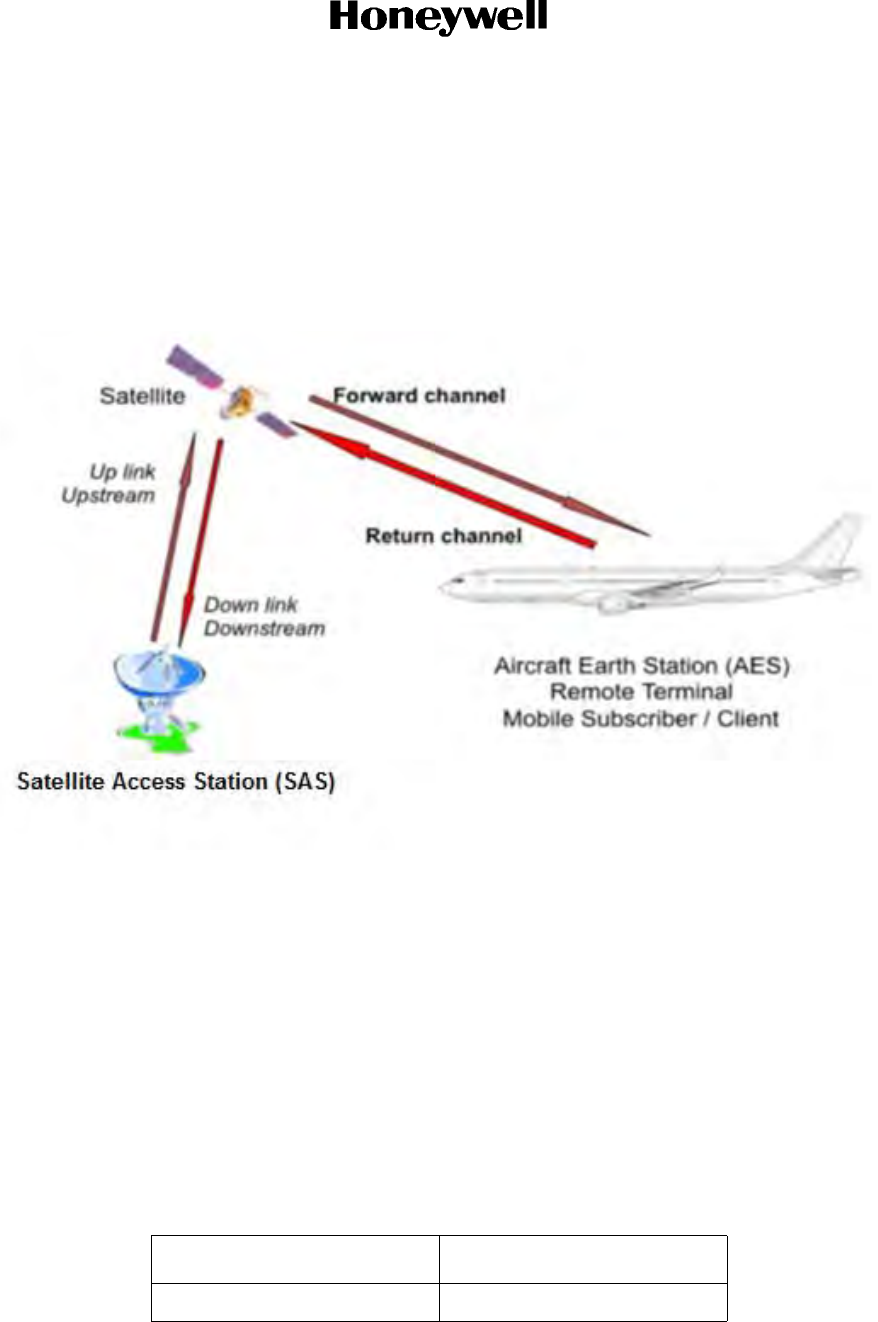
Page 1-1
16 Sep 2015
23-15-29
SYSTEM DESCRIPTION AND INSTALLATION MANUAL
JetWave™ System
© Honeywell International Inc. Do not copy without express permission of Honeywell.
DESCRIPTION AND OPERATION
1. Overall JetWave™ System Architecture
The JetWave™ SATCOM system supplies a broadband communication link that can be used to supply
data, video, and voice communications for passengers communications and entertainment. The AES
communicates to the SAS through a satellite as shown in Figure 1-1.
Figure 1-1. Ka-Band System
A Modman is provided within the AES to enable two-way communications. The forward channel provides
a communication path from the SAS to the AES. The return channel provides a communication path from
the AES to the SAS. The AES receives in the forward channel in K-band and transmits in the Ka-band.
The AES system provides the RF data link between the aircraft and the servicing satellite. An AES system
includes an antenna which is steered towards the servicing satellite by mechanical means.
The JetWave™ system operating frequency range is 29 to 30 GHz (TX, Ka-band) and 19.2 to 20.2 GHz
(RX, K-band).
A. JetWave™ System LRUs
The JetWave™ system is made up of the LRUs in Table 1-1..
Table 1-1. JetWave™ System LRUs
LRU PN
Modman 90400012-0001

Page 1-2
16 Sep 2015
23-15-29
SYSTEM DESCRIPTION AND INSTALLATION MANUAL
JetWave™ System
© Honeywell International Inc. Do not copy without express permission of Honeywell.
B. JetWave™ System LRU Leading Particulars
(1) Refer to Table 1-2 for the Modman leading particulars.
(2) Refer to Table 1-3 for the APM leading particulars.
(3) Refer to Table 1-4 for the KANDU leading particulars.
(4) Refer to Table 1-5 for the KRFU leading particulars.
(5) Refer to Table 1-6 for the TMA leading particulars.
(6) Refer to Table 1-7 for the FMA leading particulars.
(7) Refer to Table 1-8 for the B757 FMA radome perticulars.
.
APM 90401121
KANDU 90401566
KRFU CC1 90401203
KRFU CC2 90402346
KRFU 90401202
FMA 90000380-1
TMA 904000013-0001
A791 FM radome 90400017
Non-A791 FM radome 90400016
Table 1-2. Modman Leading Particulars
Characteristic Specification
Length 14.41 inches (366.0 mm) maximum
Width 5.02 inches (127.5 mm) maximum
Height 7.88 inches (200.2 mm) maximum
Weight 14.00 pounds (6.4 kg) maximum
Operating voltage 115 VAC, 400 Hz
Power consumption 60 watts maximum
NOTE: Honeywell recommends that wiring and cooling is
designed for 100 watts in order to allow for seamless upgrades
to the Modman with enhanced capability at a later date.
Power dissipation 59 watts maximum
Table 1-1. JetWave™ System LRUs (Cont)
LRU PN

Page 1-3
16 Sep 2015
23-15-29
SYSTEM DESCRIPTION AND INSTALLATION MANUAL
JetWave™ System
© Honeywell International Inc. Do not copy without express permission of Honeywell.
Cooling 48.5 lb/hr (22 kg/hr) at 104°F (40°C)
Operating temperature 5°F (-15°C) to 131°F (55°C)
Mounting information 4-MCU, forced-air, ARINC 600 series tray
Maintenance No scheduled maintenance required
Interfaces J1A - PODD, PIESD, and AISD
J1B - APM, Aircraft, APM, PODD, PIESD, AISD, and KANDU
J1C - IF to/from KRFU and aircraft power
Table 1-3. APM Leading Particulars
Characteristic Specification
Length 4.50 inches (101.6 mm) without connector
Width 4.00 inches (79.8 mm) maximum
Height 1.3 inches (33 mm) maximum
Weight 12 ounces (0.34 kg) maximum
Operating voltage 5 VDC, 300 mA maximum, from the Modman
Power consumption 0.3 watts maximum
Power dissipation 0.3 watts maximum
Cooling No forced-air cooling required
Operating temperature 5°F (-15°C) to 131°F (55°C)
Maintenance No scheduled maintenance required
Interface J1 - Modman
Table 1-4. KANDU Leading Particulars
Characteristic Specification
Length 11.02 inches (28 cm) maximum
Width 9.075 inches (23.05 cm) maximum
Height 4.76 inches (12.1 cm) maximum
Weight 8.8 pounds (4.0 kg) maximum
Operating voltage 115 VAC, 400 Hz
Power consumption 200 watts Class A maximum average power
115 watts Class B maximum average power
Table 1-2. Modman Leading Particulars (Cont)
Characteristic Specification

Page 1-4
16 Sep 2015
23-15-29
SYSTEM DESCRIPTION AND INSTALLATION MANUAL
JetWave™ System
© Honeywell International Inc. Do not copy without express permission of Honeywell.
Power dissipation 50 watts Class A maximum average power
42 watts Class B maximum average power
Cooling Cooling clearance is 2.0 inches (5.1 cm) above and 1 inch (2.54
cm) at the sides minimum
No forced-air cooling required
Operating temperature -67°F (-55°C) to 158°F (70°C)
Maintenance No scheduled maintenance required
Interfaces J1 - Aircraft and Modman
J2 - Power to OAE and IMU (38.5 and 24 VDC)
J3 - KRFU, OAE, and maintenance
J4 - Ethernet (quadrax)
Table 1-5. KRFU Leading Particulars
Characteristic Specification
Conduction-cooled 1 configuration:
Length 16.55 inches (42.0 cm) maximum
Width 10.03 inches (25.5 cm) maximum
Height 2.08 inches (7.1 cm) maximum
Weight 11.30 pounds (5.1 kg) maximum
Operating voltage 115 VAC, 400 Hz
Power consumption 150 watts maximum
Power dissipation 132 watts maximum
Cooling Conductive-cooled through the baseplate with thermal pad
Operating temperature -67°F (-55°C) to 158°F (70°C)
Maintenance No scheduled maintenance required
Interfaces J1 - Aircraft power input
J2 - Control interface from KANDU
J3 - RF TX to OAE
J4 - RF RX from OAE
J5 - IF TX from Modman
J6 - IF RX to Modman
Conduction-cooled 2 configuration:
Table 1-4. KANDU Leading Particulars (Cont)
Characteristic Specification

Page 1-5
16 Sep 2015
23-15-29
SYSTEM DESCRIPTION AND INSTALLATION MANUAL
JetWave™ System
© Honeywell International Inc. Do not copy without express permission of Honeywell.
Length 16.55 inches (42.0 cm) maximum
Width 9.01 inches (22.9 cm) maximum
Height 2.08 inches (7.1 cm) maximum
Weight 11.30 pounds (5.1 kg) maximum
Operating voltage 115 VAC, 400 Hz
Power consumption 150 watts at maximum output power
Power dissipation 132 watts at maximum output power
Cooling Conductive-cooled through the baseplate with thermal pad
Operating temperature -67°F (-55°C) to 158°F (70°C)
Maintenance No scheduled maintenance required
Interfaces J1 - Aircraft power input
J2 - Control interface from KANDU
J3 - RF TX to OAE
J4 - RF RX from OAE
J5 - IF TX from Modman
J6 - IF RX to Modman
Forced air configuration:
Length 18.05 inches (45.8 cm) maximum
Width 9.01 inches (22.9 cm) maximum
Height 3.23 inches (8.4 cm) maximum
Weight 14.6 pounds (6.6 kg) maximum
Operating voltage 115 VAC, 400 Hz
Power consumption 150 watts at maximum output power
Power dissipation 132 watts at maximum output power
Cooling Forced air, 169.8 lb/hr (77 kg/hr) at 104°F (40°C) at sea level
Operating temperature -67°F (-55°C) to 158°F (70°C)
Maintenance No scheduled maintenance required
Table 1-5. KRFU Leading Particulars(Cont)
Characteristic Specification

Page 1-6
16 Sep 2015
23-15-29
SYSTEM DESCRIPTION AND INSTALLATION MANUAL
JetWave™ System
© Honeywell International Inc. Do not copy without express permission of Honeywell.
Interfaces J1 - Aircraft power input
J2 - Control interface from KANDU
J3 - RF TX to OAE
J4 - RF RX from OAE
J5 - IF TX from Modman
J6 - IF RX to Modman
Table 1-6. TMA Leading Particulars
Characteristic Specification
Length 13.38 inches (339.9 mm) maximum
Width 12.00 inches (304.8 mm), maximum reflector sweep volume
Height 13.57 inches (344.7 mm) maximum
Weight 10 pounds (4.55 kg)
Operating voltage 38.5 VDC and 24 VDC for IMU supplied by the KANDU
Power consumption 85 watts at maximum output power
Cooling Natural convection and radiation only
Operating temperature -67°F (-55°C) to 158°F (70°C)
Maintenance No scheduled maintenance required
Interfaces J2 - Power/control interface from KANDU
J3 - RF TX from KRFU
J4 - RF RX to KRFU
Table 1-7. FMA Leading Particulars
Characteristic Specification
Length 23.03 inches (585 mm) maximum
Width 35.72 inches (907.3 mm), maximum reflector sweep volume
Height 9.40 inches (238.8 mm) maximum
Weight 83 pounds (37.6 kg) maximum
NOTE: The lifting fixture is 5.5 pounds (2.5 kg)
Operating voltage 38 VDC and 24 VDC for IMU supplied by the KANDU
Power consumption 160 watts maximum
Table 1-5. KRFU Leading Particulars(Cont)
Characteristic Specification

Page 1-7
16 Sep 2015
23-15-29
SYSTEM DESCRIPTION AND INSTALLATION MANUAL
JetWave™ System
© Honeywell International Inc. Do not copy without express permission of Honeywell.
2. Honeywell JetWave™ System Architecture
This section describes the Inmarsat AES system that Honeywell has implemented for the following
classes of terminal:
• Class A aftermarket satellite terminal: For use on CAT types of aircraft. This uses a FMA
assembly. The terminal can also be used in the large aircraft segment of the BRS.
• Class A OEM satellite terminal: For use on CAT types of aircraft but will be compliant to ARINC
791 standard.
• Class B satellite terminal: For use on BRS. This uses the compact TMA.
Both terminal types share the same core avionics, differing only in the antenna assembly. Each LRU in
the system (APM, Modman, KRFU, KANDU, and OAE) is designed to work only with other Honeywell
LRUs, not with third-party LRUs. Refer to Figure 1-2 for the JetWave™ system block diagram.
Cooling Natural convection and radiation only
Maintenance No scheduled maintenance required
Interfaces P1 - Power from KANDU
P2 - Control interface from KANDU
P3 - IMU power and control from KANDU
J4 - RF RX to KRFU
J5 - RF TX from KRFU
Table 1-8. B757 FMA Radome Leading Particulars
Characteristic Specification
Length 95.472 inches (585 mm) maximum
Width 43.881 inches (907.3 mm), maximum
Height 11.892 inches (238.8 mm) maximum
Weight 53.5 pounds (24.27 kg) maximum
Table 1-7. FMA Leading Particulars
Characteristic Specification
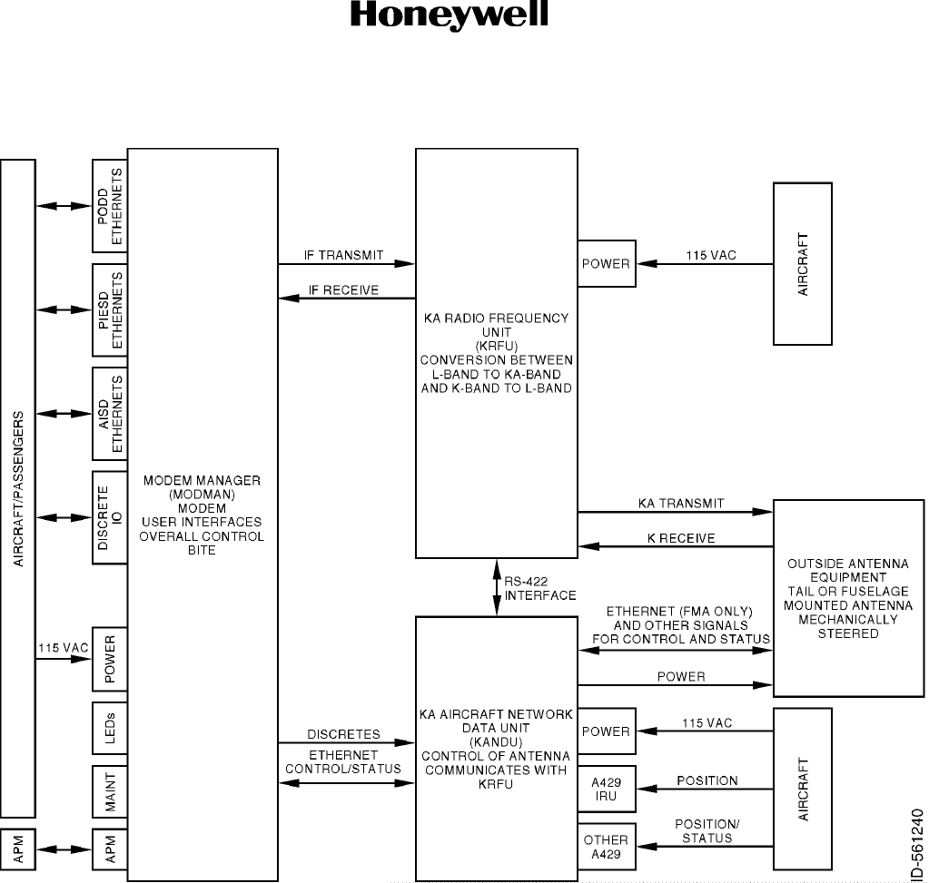
Page 1-8
16 Sep 2015
23-15-29
SYSTEM DESCRIPTION AND INSTALLATION MANUAL
JetWave™ System
© Honeywell International Inc. Do not copy without express permission of Honeywell.
Figure 1-2. JetWave™ System Block Diagram
The JetWave™ system LRUs are as follows:
A. Outside Antenna Equipment
• The OAE is made up of a mechanically steered antenna:
• Either fuselage mount or tail mount
• Radome package.
• The antenna includes an aperture.
• The OAE is powered by the KANDU.

Page 1-9
16 Sep 2015
23-15-29
SYSTEM DESCRIPTION AND INSTALLATION MANUAL
JetWave™ System
© Honeywell International Inc. Do not copy without express permission of Honeywell.
• Contains an LNA for amplification of signals in the receive path.
• Includes the mechanical pointing system, positioner, motors and sensors, and an INU to detect
movement of the platform.
• The TMA or FMA accepts the transmit Ka-band signal from the KRFU for the antenna.
• The antenna K-band receive path is amplified by the LNA and sent to the KRFU by the TMA or
FMA.
• The TMA or FMA receives power from the KANDU.
• The TMA or FMA accepts the control interface from the KANDU and lets the antenna aperture
report status, BITE, and gyro position back to the KANDU.
• Radome packages are unique to each fuselage and can be made up of the kits that follow:
• Radome kit
• A791 compliant AIM or LAIM kit
• Skirt fairing.
NOTE: Not all aircraft will have a skirt fairing.
B. KRFU
• Is made up of a BUC to convert the transmit IF frequencies (950-1950 MHz) to Ka-band
frequencies (29-30GHz)
• An HPA increases the signal strength for transmission by the antenna
• Contains a BDC to convert the received K-band frequencies (19.2-29.2 GHz) to IF (950-1950
MHz)
• Accepts 115 VAC aircraft power.
C. KANDU
• Receives commands from the Modman through an Ethernet interface to configure the
antenna/KRFU and reports status over this Ethernet interface.
• Contains the positioning algorithm to allow the pointing of the antenna with inputs from the IRU,
information from the RSSI detector in the Modman, and the IMU from the antenna.
• Provides power and control to the antenna.
• Provides control signals to the KRFU through the RS-422 interface.
• Accepts 115 VAC aircraft power.
D. Modman
• Is the overall controller of the system.
• Receives and transmits information to the KRFU along the IF frequency between 950-1950
MHz.

Page 1-10
16 Sep 2015
23-15-29
SYSTEM DESCRIPTION AND INSTALLATION MANUAL
JetWave™ System
© Honeywell International Inc. Do not copy without express permission of Honeywell.
• It supplies the user interfaces to the aircraft and passengers as follows:
• The PODD interfaces provide service to the passengers through the use of Ethernet
(10/100/1000 Base T).
• The PIESD interfaces provide services to passenger entertainment devices installed on
the aircraft (in flight entertainment systems). This system uses Ethernet (10/100/1000
Base T).
• The AISD interfaces provide services to the aircraft/cockpit, such as the electronic flight
bag, data load, etc. This system uses Ethernet (10/100/1000 Base T) interfaces.
• The discrete I/O for aircraft status and for reporting system status.
• Has two LEDs to provide power and fault status on the front panel.
• Accepts 115 VAC from the aircraft.
• Manages the BIT for the complete AES.
• Contains the modem, which transmits and receives to/from the KRFU.
• Controls the KRFU and KANDU (and through it, the OAE) through the Ethernet interface and
RS-422 discretes.
E. APM
• The APM holds the configuration data for the system.
• Is powered by the Modman.
3. Honeywell Implementation
The Honeywell implementation varies from the ARINC 791 configuration as follows:
• No ARINC 629 support is provided (optional in ARINC 791).
• No EN1 Ethernet functionality between the KRFU and KANDU is provided (the provisioned
standard inter-wiring is not utilized).
• ARINC 429 TX mute between the Modman and the KANDU is not implemented (manufacturer
specific RS422 signaling is used instead).
• Manufacturer-specific circuits 1 to 6 carry a BUC Mute signal, a Filter Select signal, and an
KANDU Reset signal.
• The RSSI function is in the Modman.
• No EN2 Ethernet interface functionality between the KANDU and OAE on the TMA variant (the
provisioned standard inter-wiring is not utilized).
• There are LED indicators on the front panel of the Modman to show status.

Page 1-11
16 Sep 2015
23-15-29
SYSTEM DESCRIPTION AND INSTALLATION MANUAL
JetWave™ System
© Honeywell International Inc. Do not copy without express permission of Honeywell.
Refer to JetWave™ AES system Configuration, AES Configuration Data for the details of ARINC 429
labels required for the JetWave™ System.
4. JetWave™ System Modes of Operation
The JetWave™ system supports the following modes of operation:
• Power On
• System Initialization
• Normal Operation
• Critical Fault
• Data-Load
• Commanded.
A. Power On Mode
Each LRU enters Power On Mode when power is applied. RF transmission is disabled in this mode.
In this mode, the Modman does POST and other invasive tests. If no failures are detected, the
system enters into the system initialization mode.
NOTE: SNMP and continuous BITE are not available at all times during this mode.
B. System Initialization Mode
In the System Initialization Mode, the Modman starts continuous BITE, system access, and SNMP
services. The Modman attempts to establish communication with KANDU and OAE. The RF
transmission is disabled in this mode.
While in System Initialization Mode, the RS422, discrete signal and the Ethernet interfaces are
available and active on all the JetWave™ LRUs which are powered up. In Modman, when powered
up, the power supply to APM is available on Modman P23B connector. When power is applied to
the KANDU LRU, the Antenna Power and IMU power is available on the KANDU receptacle J2.
Refer to the applicable interconnection diagrams for the electrical specifications of these interfaces.
There is no timeout for system initialization since the Modman, the KRFU, and the KANDU LRUs
(which power the OAE) are powered independently from the aircraft power supply.
Once the communication with other LRUs is established, the BITE parameters of other LRUs are
extracted and more system wide testing is performed. The system wide testing includes the
hardware compatibility checks, software part number compatibility check, checking for availability
of important input data and configuration files, etc. If there are no critical failures, the system enters
into the Normal Operating Mode.
C. Normal Operating Mode
In Normal Operating Mode, the RF transmission is enabled and establishment of satellite
connection is initiated subject to the system meeting the following conditions – aircraft is in the air,
there is no geographic restriction, and the antenna has a line of sight to the satellite. Ground
operation is possible if the GTE is asserted and regulatory conditions do not restrict it. The user

Page 1-12
16 Sep 2015
23-15-29
SYSTEM DESCRIPTION AND INSTALLATION MANUAL
JetWave™ System
© Honeywell International Inc. Do not copy without express permission of Honeywell.
traffic can be started once the antenna is pointed correctly to the satellite and the terminal locks on
to the satellite for providing the connectivity. The system enables all the supported services like
continuous BITE, SNMP, Access system, user services, etc. in this mode.
The system enters the Normal Operating Mode approximately 5 minutes after continuous power is
applied to the last LRU.
D. Critical Fault Mode
The system enters into Critical Fault Mode when any LRU reports a critical fault that cannot be
recovered and will affect satellite connectivity. The RF transmission is muted and user services are
disconnected. The system may support minimal services like SNMP, continuous BITE, Access
system, etc. in this mode.
E. Data Load Mode
The system enters Data Load Mode when aircraft is on ground and local data load discrete on the
Modman is asserted. The SNMP, Access System, and continuous BITE services may not be
supported in data load mode. The RF transmission is disabled in data load mode. The Modman
provides ARINC 615A Ethernet data loading to itself and other LRUs through its own interface in
Data Load Mode. Additionally, LRUs individually provide ARINC 615A data loading via their
configured ports. The APM and the KRFU do not support ARINC 615A data loading individually and
are data loaded via the Modman and the KANDU, respectively. The system can exit to Data Load
Mode when local data load discrete is asserted.
F. Commanded Mode
The system also provides a Commanded Mode of operation which may be initiated through the
SNMP when the aircraft is on ground. This mode provides access to user initiated tests for system
testing e.g. manual antenna alignment, initiating automatic antenna alignment, transmit cable
calibration, manual antenna pointing to defined location, etc.
5. About Inmarsat Services
The JetWave™ system is made up of a fleet of Ka-band broadband satellite network from Inmarsat. The
Inmarsat-5 (I-5) geostationary satellites have high power Ka-band steerable and fixed spot beams that
supply global in-flight connectivity services to business, commercial, and government aviation customers
around the world.
The JetWave™ AES provides Ka-band communication utilizing an airborne VSAT. The AES
communicates through a satellite to an SAS. TX and RX interface provided within the AES enables
two-way communication. The forward channel provides a communication path from the SAS to the AES.
The return channel provides a communication path from the AES to the SAS.
The JetWave™ system may not be available on the ground or in the air in certain geographical areas.
Some countries do not allow access to this service in their airspace. The service availability would also
depend on the country in which the aircraft is registered with. The aircraft operators may approach the
respective Value Added Resellers /Distribution Partners for further details where JetWave™ services are
not available.

Page 2-1
16 Sep 2015
23-15-29
SYSTEM DESCRIPTION AND INSTALLATION MANUAL
JetWave™ System
© Honeywell International Inc. Do not copy without express permission of Honeywell.
INSTALLATION
1. Overview
A. JetWave™ System Components
The JetWave™ system includes five LRUs:
• Modman
•APM
• KANDU
•KRFU
• OAE - either a TMA or FMA.
NOTE: OAE equipment must be installed within an approved radome.
B. Installation Procedure Overview for the JetWave™ System
The overview of the installation procedure for the JetWave™ system is as follows:
(1) Install adapter plate for the FMA. The adapter plates required for mounting the FMA are
available in installation kits from various suppliers.
(2) The TMA is installed on the top ribs of the tail of the aircraft. In some cases an install bracket
can be used.
(3) Install the OAE and JetWave™ components in accordance with the installation drawings.
(4) Install wiring in accordance with the interconnection diagram. The cables and adapters are
available as installation kits from various suppliers.
(5) Do wiring and RF cable checks to make sure they are installed correctly and meet the
installation requirements.
(6) Apply power to the system.
(7) Do the post-installation checks.
(8) Test the system on the ground if local regulations permit.
2. Certification and Approvals
All antenna installations must be inspected and approved by an FAA authorized Designated Engineering
Representative and must be documented on FAA form 8110-3.
3. On-ground Testing and Commissioning
NOTE: There are restrictions to testing the JetWave™ system for the commissioning process.
NOTE: Each country has its own restrictions to on-ground testing and transmission. Verify regulations
before testing the system. Particular attention must be observed the first time the system is turned
on and able to transmit. At this point the system will download a map detailing the areas where
transmission is and is not allowed. This map will take effect on the next power-up.

Page 2-2
16 Sep 2015
23-15-29
SYSTEM DESCRIPTION AND INSTALLATION MANUAL
JetWave™ System
© Honeywell International Inc. Do not copy without express permission of Honeywell.
A. Testing and Commissioning Process with Restrictions
(1) The JetWave™ system under normal operating conditions mutes and disables the modem
when the Air/Ground status in "On Ground".
(2) The Air/Ground status will be set to "On Ground" when one of the conditions that follow are
met:
• Weight on wheels discrete is enabled in the system configuration and is indicating
"Weight on Wheels”.
•The ground speed is less than 50 knots.
• The JetWave™ system is configured to receive ground speed labels on an ARINC 429
bus but the ground speed readings have not been available for longer than 20 seconds.
(3) Ground transmission can be enabled by asserting the ground transmit discrete of JetWave™
system.
(a) The ground operation depends on location and country of aircraft registration.
(b) The reason for restrictions on transmission from the current aircraft location can be
accessed through the GUI Home page under text display “Reasons for Transmission
mute”.
(4) On completion of JetWave™ LRU installation activities, the AES system needs to be
commissioned by associating the installed JetWave™ AES system to a specific SSPP. This
SSPP may correspond to an actual VAR but may also point to a test VAR in case the actual
VAR or SSPP is not known at the time the terminal integration is finalised. The operational
life commences once the AES system is commissioned.
(5) For the testing and commissioning process, the aircraft must be positioned so to have a clear
line of sight to the satellite.
(6) To control the transmission of the terminal within certain locations and at different heights,
the terminal stores and uses a geographical map. The map indicates regions around the
globe where the terminal may legally transmit. The map is provided by Inmarsat and
requested by the terminal when it first enters the network. The terminal will retrieve the map
file from the Inmarsat server using the FTP protocol over a SVN. The SVN used for the geo
restrictions maps shall be [2] NSD Management VLAN.
(7) The APM is configured with information pertaining to the aircraft and the terminal installation.
The two important aspects of APM configuration with respect to commissioning of the
terminal are as follows:
• The private authentication key which is used to uniquely identify the logging data
transmitted by the aircraft to the regulatory server on the ground.
• The aircraft identification “Tail ID”.
(8) The Modman houses the ACM.
(a) The ACM directly connects and interacts with the JetWave™ NMS.
(b) The ACM embeds a private secret key that allows it to be recognized by the NMS as a
“Satellite Router”.

Page 2-3
16 Sep 2015
23-15-29
SYSTEM DESCRIPTION AND INSTALLATION MANUAL
JetWave™ System
© Honeywell International Inc. Do not copy without express permission of Honeywell.
(c) At the time of manufacturing of Modman, the serial numbers of the Modman and
associated DIDs of the ACM are communicated to the Inmarsat service provider as part
of pre-provisioning.
(d) The Modman and associated DIDs of the ACM also allocated a specific SSPP. This
SSPP is required to verify the terminal connectivity to the NMS.
(9) When commissioning a terminal, a VAR has to assign a service plan to the subscriber which
becomes effective by associating an SSPP to the JetWave™ AES system.
4. JetWave™ System LRU Installation
This section includes information about installing the equipment in the core JetWave™ system. Contact
Honeywell about installation kits that include mating connectors and cables.
Honeywell recommends that LRUs be installed in accessible locations that are compatible with the
environmental levels that the equipment is certified to handle.
Refer to APPENDIX D for the installation reference checklist.
A. Maintenance Panel
If the JetWave™ system is not wired to other systems on the aircraft, the discrete I/O and Ethernet
ports must be brought out to a suitable panel to allow for system checks and routine maintenance,
such as system software upgrades. The discrete I/O and Ethernet ports that are needed are as
follows:
(1) Discrete Outputs:
• System available (Modman MP13E) connected to a lamp
• Data link available (Modman MP13F) connected to a lamp.
(2) Discrete Inputs:
• Local data load enable (Modman MP10B) connected to a normally open switch
• Ground transmit enable (Modman MP11D) connected to a normally open switch
• Public service disable (Modman MP11E) connected to a normally open switch
• Modman reset (Modman MP10C) connected to a normally open switch.
(3) Ethernet Port:
• AV1 (Modman TP BB1 thru 4) connected to a RJ45 Ethernet connector
NOTE: The AVI is the default data loading port, any other Ethernet ports can be selected as
long as the APM configuration file is configured to allow that port to data load.
For LRU pin details, refer to the applicable system interconnect diagram, Figure 2-33 thru
Figure 2-36.
B. Modman

Page 2-4
16 Sep 2015
23-15-29
SYSTEM DESCRIPTION AND INSTALLATION MANUAL
JetWave™ System
© Honeywell International Inc. Do not copy without express permission of Honeywell.
Install the Modman in a standard 4-MCU tray. The customer is responsible for providing the
mounting tray, the mating ARINC 600 connector, contacts, as well as all the cabling for the
installaton.
Refer to Figure 2-24 for outline and installation information, and Figure 2-33 thru Figure 2-36 for
the applicable interconnect diagram.
There are no special tools, fixtures, and equipment required for the Modman installation.
Minimum clearance for the Modman: 1.0 inch (25.4 mm) clearance from top face, 0.5 inch (12.7
mm) clearance from all the other faces not interfacing with the mounting tray.
(1) The Modman mounting kits are as follows:
The customer is responsible for providing the mounting tray. Carlisle Interconnect
Technologies supplies 4-MCU ARINC 600 kits in various configurations, contact Carlisle at
www.carlisleit.com.
(2) The Modman connectors are as follows:
Table 2-1 provides the connector part numbers for the Modman rear connector. The mating
connector (Radiall PN NSXN2B875S00) is supplied by the customer.
NOTE: While engineering the JetWave™ System LRU interconnections, make sure the GXA LRU
quadrax terminations do not distort natural wire distortions. There are geometric
relationships that must be maintained between the quadrax contact and the natural twist of
the star-quad wire. Wire bend radii and clamping conditions typical of aircraft installations
should not cause deviation from NEXT parameters of the A664 compliant star quad cables
Table 2-1. ARINC 600 Connectors
Connector PN Description Qty
Radiall PN 620 601 191 ARINC 600 connector shell Size 2 with inserts 1
Insert A:
Radiall PN 620075050
Arrangement Q11, Shell Size 2:
Size 8 quadrax contact for Ethernet connections 11
Insert B:
PN: D38999/26FH35PN
D38999/26FD35PN
Radiall PN 620075050
Arrangement 120Q2, Shell Size 2:
#22 contacts
Size 8 quadrax contact for Ethernet connections
118
2
Insert C:
PN: D38999/26FE6PN
PN: D38999/26FE6PN
PN: not included
PN: 620022
Arrangement 12F5C2, Shell Size 2:
#12 contacts
#16 contacts
Size 16 optical contacts (not used)
Size 5 coax contact for RF connections
4
1
5
2

Page 2-5
16 Sep 2015
23-15-29
SYSTEM DESCRIPTION AND INSTALLATION MANUAL
JetWave™ System
© Honeywell International Inc. Do not copy without express permission of Honeywell.
for Ethernet interfaces terminating on Quadrax receptacles. Refer to the applicable
interconnection diagrams for the indicator that the connector rotation of the wire is in a
clockwise direction.
(3) The Modman bonding is as follows:
The Modman must be electrically bonded to the airframe. Make sure that the mating surfaces
are free from contaminants such as paints or other non-conductive elements. A bonding test
point is available on the front panel. The bonding resistance must be less than or equal to 2.5
mΩ.
(4) The TX and RX IF cables between the Modman and KRFU must have a minimum loss of
11dB at 950 MHz and a maximum loss of 21.2 dB at 950 MHz.
If the chosen cable loss is too small, an equalizer should be inserted in the TX path and an
attenuator in the RX path. The choice of parts are detailed in Table 2-2.
NOTE: An attenuator cannot be used in the TX path as the TX path also passes the
reference to the KANDU and the attenuator will introduce too much loss to that
portion of the signal.
C. APM
The APM can be installed in any orientation. Refer to Figure 2-25 for outline and installation
information and Figure 2-33 thru Figure 2-36 for the applicable interconnect diagram.
There are no special tools, fixtures, and equipment required for the APM installation.
There are no clearance requirements for the APM.
Use 0.164-32 UNC-2A corrosion resistant mounting fasteners. Do not exceed 25 in-lb (2.8 Nm)
when you torque the screws.
Connect the APM to the Modman with cable made up of two twisted shielded 24 AWG pairs with
Teflon insulation or aerospace grade shielded CAT5/CAT5e cable, with a maximum length of 9.8
feet (3 m).
The APM to Modman pendant cable, Honeywell recommends ECS PN 92240 or equivalent that is
a composite (a shielded conductor bundle) construction to support the environmental conditions
required.
Table 2-2. Modman Cable Loss Values
Cable Loss @ 950 MHz
< 6.5 dB > 6.5 dB, <11 dB > 11 dB
Equalizer in TX path 10.5 dB
Minicircuits, PN TA-10R5DC1
or equivalent
4.8 dB
Minicircuits, PN TA-4R8DC1
or equivalent
None
Attenuator in RX path 10.5 dB
Minicircuits, PN TAT-10R5-1
or equivalent
4.8 dB
Minicircuits, PN TAT-4R8-1 or
equivalent
None

Page 2-6
16 Sep 2015
23-15-29
SYSTEM DESCRIPTION AND INSTALLATION MANUAL
JetWave™ System
© Honeywell International Inc. Do not copy without express permission of Honeywell.
The APM must be electrically bonded to the airframe through contact with the base of the unit or
through a bonding cable attached to M3 earth stud. The APM bonding resistance must be less than
or equal to 2.5 mΩ.
D. KANDU
Refer to Figure 2-26 for outline and installation information. Refer to Figure 2-33 thru Figure 2-36
for the applicable interconnect diagram.
There are no special tools, fixtures, and equipment required for the installation of the KANDU.
The customer is responsible for the bulkhead connectors.
(1) KANDU to FMA bulkhead interconnect specification is as follows:
(a) Power and control signals required for the JetWave™ system LRUs installed outside the
aircraft will be routed through the power and control bulkhead interface connectors
which will be sealed to maintain cabin pressure (max 14.5 PSI (1,000 hPa)) inside the
cabin.
(b) Maximum round trip wiring interconnection resistance between KANDU A3J2 and
OAE-FMA- A5P1 must not exceed 0.326 ohms (considering the 16 AWG wire cables of
length 32.8 feet (10 m)).
(c) It is recommended to use MIL-DTL-38999 series III, insert 19-35, normal keying with 66
contacts as KANDU bulkhead control connector for KANDU interwiring to the
OAE-FMA. To be labeled as BI-control.
(d) It is recommended to use MIL-DTL-38999 series III, insert 17-8, normal keying with eight
contacts as KANDU bulkhead power connector. To be labeled as BI-power.
(e) It is recommended to use TNC/N-Type hermetically sealed bulkhead interface in
accordance with MIL-C-87104/2 for the routing of the TX-IF signals between the
Modman and KRFU. The TX-IF interface to be labeled blue.
(f) It is recommended to use TNC hermetically sealed bulkhead interface in accordance
with MIL-C-87104/2 for the routing of the RX-IF signals between the Modman and
KRFU. The RX-IF interface to be labeled green.
(g) The bulkhead interface design must be jam-nut or flange in consultation. If flange design
connector is used, it must be installed such that the flange is located on the pressurized
area of the aircraft. If jam nut connector is used, jam-nut connector should utilize a lock
wire.
(h) Bulkhead interface should be installed such that receptacle pins are on the pressurized
area and receptacle sockets are on unpressurized side of the aircraft.
(i) The bulkhead interface connectors must be electrically bonded to the aircraft.
(2) KANDU to TMA interconnect specification is as follows:
(a) KANDU receptacle A3J1 is MIL-DTL-38999/20FD19PN, series Ill, flange mount
receptacle, insert 15-19, normal keying, with 19 pin-type contacts of size 20 AWG.
Mates with D38999/26FD19SN for aircraft interface.

Page 2-7
16 Sep 2015
23-15-29
SYSTEM DESCRIPTION AND INSTALLATION MANUAL
JetWave™ System
© Honeywell International Inc. Do not copy without express permission of Honeywell.
(b) KANDU receptacle A3J2 is MIL-DTL-38999/20FC4SN, series Ill, flange mount
receptacle, insert 13-4, normal keying, with four socket-type contacts of size 16 AWG.
Mates with D38999/26FC4PN for power output.
(c) KANDU receptacle A3J3 is MIL-DTL-38999/20FG35PN, series III, flange mount
receptacle, insert 21-35, normal keying, with 79 pin-type contacts of size 22 AWG.
Mates with D38999/26FG35SN for control interface.
(d) KANDU receptacle A3J4 is TVPOORGQF-21-75P (Amphenol) or equivalent. Mates
with TV06RQF-21-75S (Amphenol) or equivalent for Ethernet interface.
(e) Maximum round trip wiring interconnection resistance between KANDU A3J2 and
OAE-TMA A5J2 must not exceed 0.684 ohms (considering 20 AWG wire cables of
length 32.8 feet (10 m)).
(f) KANDU bonding to the aircraft must be achieved through the mounting structure
(fasteners) and KANDU A3J1-A.
The bulkhead interface is as follows:
(g) It is recommended to use MIL-DTL-38999 series III, insert 19-35, normal keying with 66
contacts as KANDU bulkhead control connector for KANDU inter-wiring to MODMAN if
KANDU is installed in an unpressurized location inside aircraft.
(h) It is recommended to use MIL-DTL-38999 series III, insert 19-35, normal keying with 66
contacts as KANDU bulkhead control connector for KANDU inter-wiring to KRFU and
OAE-TMA if KANDU is installed in pressurized location inside aircraft.
(i) It is recommended to use MIL-DTL-38999 series III, insert 17-8, normal keying with eight
contacts as KANDU bulkhead power connector if 115 VAC power is not provisioned in
unpressurized location of aircraft.
(j) The bulkhead interface design could be either jam-nut or flange in consultation. If flange
design connector is used, it must be installed such that the flange is located on the
pressurized area of the aircraft. If jam nut connector is used, jam-nut connector should
utilize a lock wire.
(k) Bulkhead interface must be installed such that receptacle pins are on the pressurized
area and receptacle sockets are on unpressurized side of the aircraft.
(l) The bulkhead interface connectors should be electrically bonded to the aircraft.
(3) The KANDU must be electrically bonded to the airframe through contact with the base of the
unit as follows:
• At least one of the four mechanical attachment points must be used for electrical
bonding. Make sure that the mating surfaces are free from contaminants such as
paints or other non-conductive elements.
• A circular or elongated conductive area must be provided around the mounting hole
of the equipment base plate. A diameter of the conductive area must be 0.12 inch (3
mm) larger than the diameter of the washer.
• The KANDU must include a 0.59 inch (15 mm) diameter bonding measuring point
on one of the attachment tabs, as near as possible to the bonding element, but not
on the bonding element.

Page 2-8
16 Sep 2015
23-15-29
SYSTEM DESCRIPTION AND INSTALLATION MANUAL
JetWave™ System
© Honeywell International Inc. Do not copy without express permission of Honeywell.
The KANDU bonding resistance measured from the measuring point and the surface the unit
is mounted must be less than 2.5 mΩ.
E. KRFU
A waveguide is used for the KRFU to OAE RF TX connection. The waveguide run must include a
short length of seamless flexible waveguide along the routing to accommodate tolerances. The
waveguide must have mounting points to interface to the attachment points provided.
NOTE: A coax cable can be used in the place of the waveguide as long as the total loss number is
met.
The requirements for waveguide installation vary for each aircraft.
NOTE: Make sure the waveguide is connected before powering the KRFU. Always connect J1 last
and disconnect J1 first (J1 contains the A/C power).
Refer to Figure 2-27, Figure 2-28, and Figure 2-29 for outline and installation information. Refer to
Figure 2-33 thru Figure 2-36 for the applicable interconnect diagram.
There are no special tools, fixtures, and equipment required for the installation of the KRFU.
For FMA configuratiions, Honeywell recommends that the WR28 to WR34 adapter is put at the
KRFU end of the cable.
The TX path interconnect loss between the KRFU and the FMA must not exceed 1.5 dB. The
loss is from KRFU flange to antenna flange.
The RX path interconnect loss between the KRFU and the FMA must not exceed 2.9 dB.
The KRFU to TMA connection must be WR28 for TX, coax for RX. The KRFU to FMA WR34
connection needs to include an adapter for TX to adapt from WR28 to WR34.
The TX path interconnect loss between the KRFU and the TMA must not exceed 0.6 dB.
The RX path interconnect loss between the KRFU and the TMA must be a minimum of 0.5
dB, not exceed 2 dB.
NOTE: RX connection requires a transition from coax to WR42 at the KRFU.
Honeywell recommends that the WR42 to coax adapter is put at the KRFU end of the cable.
The operation of the AES is limited if the conduction-cooled KRFU is installed under the radome
and the mounting plate temperature exceeds 185°F (85°C).
If the shutdown temperature is exceeded, a low-power mode (non-RF communicating) is entered
until the temperature reduces to approximately ten degrees below the shutdown temperature. Refer
to Figure 3-20 for the temperature status report.
NOTE: When the aircraft is on the ground and the AES is transmitting, and the ambient outside
temperature is very hot, then the mounting plate temperature can be exceeded. The exact
outside air temperature and operating conditions are installation dependent. Consult with
your hardware supplier for further details.

Page 2-9
16 Sep 2015
23-15-29
SYSTEM DESCRIPTION AND INSTALLATION MANUAL
JetWave™ System
© Honeywell International Inc. Do not copy without express permission of Honeywell.
The KRFU must be electrically bonded to the airframe through contact with the base of the unit as
follows:
• At least one of the four mechanical attachment points must be used for electrical
bonding.
• Make sure that the mating surfaces are free from contaminants such as paints or
other non-conductive elements.
• A circular or elongated conductive area must be provided around the mounting hole of
the equipment base plate.
• A diameter of the conductive area must be 0.12 inch (3 mm) larger than the
diameter of the washer.
• The KRFU must include a 0.59 inch (15 mm) diameter bonding measuring point on one
of the attachment tabs, as near as possible to the bonding element, but not on the
bonding element.
The KRFU bonding resistance measured from the measuring point and the surface upon which the
unit is mounted, must be less than 2.5 mΩ.
The KRFU bonding and KRFU interconnection details from and to either the TMA or FMA are
detailed along wiht the TMA or FMA installation instructions in subsequent sections.
F. KRFU Thermal Pad Kit
(1) General
(a) The thermal pad kit, PN SCD-90402388, is intended to provide a conduction interface
between the bottom surface of the KRFU conduction units of two configurations, PN
90401203 and PN 90402346, and airplane cold plate or mounting panel. Before
mounting units on airplane the thermal pad must be installed on the units.
(2) Kit contents
(a) The thermal pad kit, PN SCD-90402388, contains the parts identified in Table 2-3.
(3) To install the thermal pad kit, do as follows:
(a) Turn the KRFU conduction unit over to expose bottom side.
(b) The thermal pad kit is made up of two different pads. There is a clear backing material
protecting the tacky side of the pads and a white opaque backing material protecting the
non-tacky side of the pads.
(c) Remove the clear protective backing to expose the tacky side of the thermal pad PN
MPW0000118.
Table 2-3. Thermal Pad Kit Contents
PN Description Quantity
MPW0000118 Thermal pad, conduction, 60 Mil T-Flex Ka airborne, Part 1 1
MPW0000122 Thermal pad, conduction, 60 Mil T-Flex Ka airborne, Part 2 1
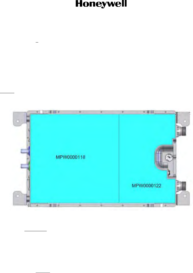
Page 2-10
16 Sep 2015
23-15-29
SYSTEM DESCRIPTION AND INSTALLATION MANUAL
JetWave™ System
© Honeywell International Inc. Do not copy without express permission of Honeywell.
(d) Apply tacky side of thermal pad to the bottom side of unit as shown in Figure 2-1.
1Making sure to keep a setback dimension of 0.032 to 0.125 inch (0.79 to 3.18 mm)
around the edges of the installed thermal pad.
(e) Remove the clear protective backing to expose the tacky side of thermal pad PN
MPW0000122.
(f) Apply the pad flush to the interior edge of the thermal pad PN MPW0000118, in order to
maintain consistent setback dimension of 0.032 to 0.125 inch (0.79 to 3.18 mm) around
the edges of the installed thermal pad.
NOTE: The configuration of the mounting feet shown in Figure 2-1 is representative only and may not be
the exact configuration for all KRFUs.
Figure 2-1. KRFU Thermal Pads
CAUTION: THE THERMAL PAD OPAQUE PROTECTIVE BACKING MUST BE
REMOVED FROM BOTH THERMAL PADS BEFORE USE IN THE FINAL
APPLICATION. FAILURE TO DO SO CAN RESULT IN PREMATURE
SHUTDOWN OF THE KRFU DUE TO OVERHEATING.
(g) Immediately before installing the KRFU into the aircraft, remove white opaque protective
backing on both pads to expose the non-tacky side of the thermal pad.
NOTE: If the KRFU unit is to be shipped or stored before installation, do NOT remove
the white opaque backing on the thermal pads.
G. Deleted
H. Deleted
I. Tail Mount Antenna

Page 2-11
16 Sep 2015
23-15-29
SYSTEM DESCRIPTION AND INSTALLATION MANUAL
JetWave™ System
© Honeywell International Inc. Do not copy without express permission of Honeywell.
(1) Introduction
The TMA assembly is to be installed on the top of the tail empennage of the aircraft. For the
JetWave™ system to correctly point the antenna, the installation offsets should not exceed
more than 1 degree off heading, pitch or roll with respect to principle axis of aircraft.
Depending on the airframe, the LRUs and assemblies that follow would be installed outside
aircraft fuselage as part of tail mount OAE:
•The TMA assembly
• KRFU LRU
• Radome assembly
• Radome fairing (if required).
The exact install location of the TMA assembly and KRFU is airframe specific.
The radome, radome fairing (if required), and TMA/KRFU to aircraft interface brackets are
airframe specific and the details are not covered in this manual.
Consideration must be given when deciding where to install the antenna on the factors that
follow:
• Other antennas or equipment that may block the JetWave™ antenna from being able to
see the satellite
• The JetWave™ antenna blocking other antennas
• Potential interference by the JetWave™ transmitted signal degrading the received signal
of other aircraft RF systems
• Potential interference by other RF systems degrading the received signal of the
JetWave™ system.
The TMA complies with form as defined in JetWave™ TMA outline and installation drawing
in Figure 2-30, the KRFU outline and installation drawing Figure 2-28, and the interconnect
diagram in Figure 2-33.
Refer to Table 2-4 for special tools, fixtures, and equipment for the TMA installation.
Antenna clearance for sweep volume is 12 inches (304.8 mm) minimum around dish sweep
area.
(2) TMA Installation General
Before installing any components or cabling, read all notes on drawings and read all
installation procedures.
Table 2-4. Special Tools for TMA Installation
Number Description Source
NA Hoist system Commercially available

Page 2-12
16 Sep 2015
23-15-29
SYSTEM DESCRIPTION AND INSTALLATION MANUAL
JetWave™ System
© Honeywell International Inc. Do not copy without express permission of Honeywell.
The installer must select the appropriate gauge of wire as specified in the TMA
interconnection diagram in Figure 2-33 for power and control connections. Interconnect
cables must be routed away from sources of potential electromagnetic interference.
(3) Advisories
The JetWave™ TMA and the KRFU subsystems include components that radiate RF and
microwave emissions in the band between 29.0 and 30.0 GHz.
All service technicians and operators should be informed of the potential hazards of RF and
microwave radiation. When installing and servicing equipment, exercise the safety
precautions that follow.
WARNING: THIS EQUIPMENT RADIATES HIGH FREQUENCY RADIATION AND POSES A
RADIATION HAZARD. CONSIDERING THE WORST CASE CONDITION OF 100
PERCENT REFLECTION FOR TAIL MOUNT ANTENNA, HONEYWELL DEEMS IT
NECESSARY TO ASSURE OEM FUSELAGE ATTENUATION EXCEEDS 19.48 dB FOR
TAIL MOUNTED ANTENNAS SYSTEM INSTALLATION. THIS IS THE MINIMUM
ATTENUATION REQUIRED FROM THE AIRCRAFT FUSELAGE TO ATTENUATE THE
KA BAND RADIATION TO MEET A SAFE HUMAN EXPOSURE OF 1 MW/CM2 INSIDE
THE AIRCRAFT.
WARNING: SERVICE TECHNICIANS AND OPERATORS MUST EXERCISE CARE TO KEEP
CLEAR OF THE ANTENNA’S BEAM WHILE PERFORMING OPERATIONAL TESTS OR
INSTALLATION VERIFICATION PROCEDURES. DO NOT APPROACH WITHIN 30.3
FEET (9.24 METERS) OF THE TAIL MOUNT ANTENNA ASSEMBLY DURING RADIO
FREQUENCY TRANSMISSION
WARNING: DURING ANTENNA OPERATION (TRANSMISSION), ENSURE MINIMUM EXPOSURE
OF ALL PERSONNEL TO ANY REFLECTED, SCATTERED, OR DIRECT BEAMS.
CAUTION: SERVICE TECHNICIANS MUST OBEY STANDARD SAFETY PRECAUTIONS, SUCH AS
WEARING SAFETY GLASSES, TO PREVENT PERSONAL INJURY WHILE
INSTALLING OR PERFORMING SERVICE ON THIS UNIT.
(4) TMA Unpacking and Inspection
This section describes how to make sure that the equipment is in good condition after
shipping. To unpack and inspect the equipment, do as follows:
(a) Unpack the equipment components from the shipping container.
(b) Make sure that all the components of the tail mount OAE subsystem as indicated on the
parts list / bill of materials are included.
(c) Visually inspect the units for any shipping damage.
(5) TMA Installation Kit Details
Other than the parts list specified in Figure 2-5, the installation kit for waveguide and coax
assemblies, wiring assemblies, brackets, clamps and mounting assembly will be airframe
specific. Refer to airframe specific wiring diagram for details.

Page 2-13
16 Sep 2015
23-15-29
SYSTEM DESCRIPTION AND INSTALLATION MANUAL
JetWave™ System
© Honeywell International Inc. Do not copy without express permission of Honeywell.
CAUTION: THE TAIL MOUNT OAE ASSEMBLY IS ELECTROSTATIC-SENSITIVE. STANDARD
ELECTROSTATIC-SENSITIVE HANDLING PROCEDURES MUST BE OBSERVED.
(6) TMA Airframe Structural Modifications
For the installation of TMA, structural modifications to the tail empennage of the airframe may
be required to accommodate the additional mass of the antenna assembly and aerodynamic
loads.
The aerodynamic loads are dependent on the aircraft type as well as the installation location
of the tail mount antenna assembly and KRFU on the aircraft, and are therefore installation
specific.
The appropriately qualified personnel should derive the loads and perform a structural
analysis to verify the suitability of the modifications.
The installer is responsible for all structural modifications to the aircraft.
(7) TMA Mounting Guidelines
This section describes the mounting guidelines for the tail mount OAE.
The radome installation is aircraft specific.
The airframe manufacturer can be consulted to determine the torque requirements for
mounting the TMA assembly, KRFU, radome, and radome fairing for each unique installation.
(8) TMA Physical Placement
The TMA and KRFU must be mounted on the top of the tail empennage for clear satellite
communications. Figure 2-2 shows a typical installation location for the tail mount antenna
assembly on an aircraft.
Figure 2-2. TMA Installation Location
Table 2-5. TMA Installation Kits
PN Description
SCD-90402677 WR42 to 2.92 mm coax adapter
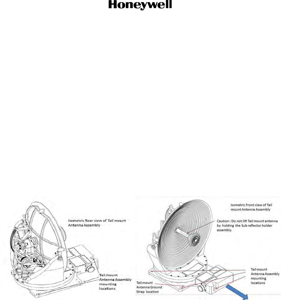
Page 2-14
16 Sep 2015
23-15-29
SYSTEM DESCRIPTION AND INSTALLATION MANUAL
JetWave™ System
© Honeywell International Inc. Do not copy without express permission of Honeywell.
(9) TMA Interface Mount Brackets (if Required)
Depending on the airframe, there may be a need to install a TMA to airframe interface mount
brackets, which adapts to the tail empennage of the aircraft and in turn supplies a firm flat
base for the TMA assembly.
This is not detailed in this document as the requirement of antenna interface mount is air
frame specific.
(10) TMA Radome and Radome Fairing
Depending on the airframe, there may be a need to install radome fairing which adapts to the
tail empennage of the aircraft.
This is not detailed in this document as the requirement of radome fairing is airframe specific.
(11) TMA Assembly
The tail mount OAE assembly is typically mounted on the Ku SATCOM radio slot on top of
empennage of the aircraft vertical stabilizer.
Consult the airframe manufacturer for identification of appropriate airframe specific
installation slots on the empennage.
The isometric rear and front views of the TMA assembly is shown in Figure 2-3.
Figure 2-3. TMA Assembly Isometric View
The TMA assembly attaches to the base in five (05) locations. Refer to Figure 2-3 and Figure
2-30 for details.
(12) TMA Assembly Orientation
Orientation of the TMA assembly is defined with respect to the principal axes of the aircraft.
The TMA assembly is to be installed such that the TMA J2 connector side is located towards
the front of aircraft as indicated by the arrow as shown in Figure 2-3.
(13) KRFU Installation Location with the TMA
The KRFU install location at the top of aircraft tail empennage is airframe specific.
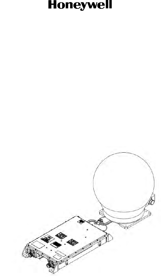
Page 2-15
16 Sep 2015
23-15-29
SYSTEM DESCRIPTION AND INSTALLATION MANUAL
JetWave™ System
© Honeywell International Inc. Do not copy without express permission of Honeywell.
The KRFU can be installed either on front or rear of tail mount antenna assembly horizontally
or vertically depending on space availability.
The KRFU is conduction cooled through the base plate with thermal pad. Mount the
Honeywell recommended thermal pad (refer to KRFU Thermal Pad Kit installation in section
3.F.) while installing KRFU LRU.
The KRFU must be installed close to the TMA assembly so as to minimize the
waveguide/coax RF losses on the RF interconnect.
It is recommended to use flexible waveguide/coax RF interface with interconnect losses not
exceeding 0.6 dB on the transmit path and 2 dB on the receive path between the KRFU and
the TMA assembly.
The typical KRFU LRU and TMA assembly (swept volume model of antenna shown)
interconnect arrangement is shown in Figure 2-4.
Figure 2-4. KRFU and TMA Interconnect Arrangement
(14) TMA Bonding Requirements
The ground straps are installed before proceeding with installation of the TMA assembly on
the antenna adapter plate or on the tail empennage airframe structure. The TMA assembly
and KRFU must be bonded to the airframe.
Consult the airframe manufacturer for the correct torque values.
J. OAE TMA Installation Procedure
Before doing any installation procedures, the installer must read and be aware of the safety
advisories listed in this manual. Only authorized technical personnel who are trained in general
aviation workmanship and have a basic understanding of satellite communication systems should
proceed with the following installation procedure.
The installation activities are detailed in subsequent sections as follows:
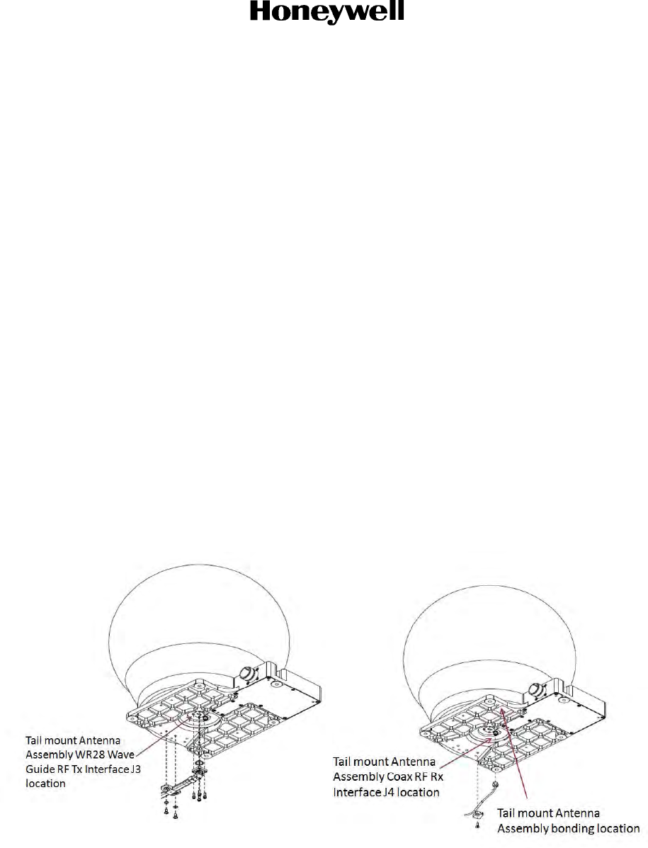
Page 2-16
16 Sep 2015
23-15-29
SYSTEM DESCRIPTION AND INSTALLATION MANUAL
JetWave™ System
© Honeywell International Inc. Do not copy without express permission of Honeywell.
• Connecting the waveguide, RF coax interface to the TMA.
• Positioning and installation of the TMA assembly onto tail empennage antenna slot/antenna
interface mount, installation of bonding straps.
• Installation of the KRFU and bonding straps.
• Installation of the waveguide and coax between the TMA and KRFU.
• Connecting the TMA interface, KRFU power, and control interfaces.
• Position and installation of the radome.
(1) Waveguide and RF Coax interconnection to Tail Antenna assembly
The waveguide and RF coax interconnect designs are aircraft specific. Consult aircraft
specific SDIM for detailed installation instructions.
(2) Installation of the TMA Assembly
(a) Carefully position and secure the TMA assembly to antenna interface mount / tail
empennage structure by making sure that the aligning stubs are aligned and fitted
correctly to the TMA alignment groves.
(b) Loosely connect and hand tight the TMA assembly with fasteners at the five mounting
locations. Apply the specified torque to the fasteners in defined sequence for firmly
mounting to the antenna interface mount / tail empennage of the aircraft.
(c) Connect the bonding strap to the TMA assembly. Refer to Figure 2-5 for the bonding
strap location.
Figure 2-5. TMA RF TX J3 and RF RX J4 Interface Connector and Bonding Strap Locations
(3) KRFU Installation
(a) Make sure that the thermal pads are attached to the bottom of the KRFU. Refer to
Section 3.F. KRFU Thermal Pad Kit.
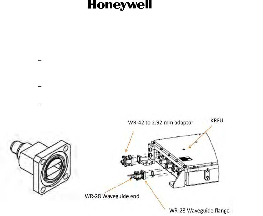
Page 2-17
16 Sep 2015
23-15-29
SYSTEM DESCRIPTION AND INSTALLATION MANUAL
JetWave™ System
© Honeywell International Inc. Do not copy without express permission of Honeywell.
(b) Before proceeding with the KRFU installation, connect the WR42 waveguide to 2.92 mm
coaxial connector adapter to KRFU J4 RF RX.
1The adapter allows connection between a WR-42 waveguide cover flange
UG595/U per MIL-DTL-3922/54 (modified with threaded mounting holes) and a
2.92 mm coaxial connector.
2The WR42 waveguide side of the adapter has a mechanical flange interface with
four 0.117 inch (2.97 mm) diameter through holes for mating with KRFU J4.
3The WR42 waveguide to 2.92 mm coaxial connector adapter is shown in Figure 2-6.
Figure 2-6. WR42 Waveguide to 2.92 mm Coaxial Connector Adapter
(c) Remove the protective covers from the KRFU J4 and WR42 waveguide to 2.92 mm
coaxial connector. Visually inspect connector ends and make sure that there is no debris
in the cavities.
(d) Install an O-ring and mount the adapter onto KRFU J4 with four screws. Firm tight the
WR42 waveguide to 2.92 mm coaxial connector to KRFU waveguide flange for all
fasteners in opposite sequences. Do not use power tools to torque connection.
(e) Attach the KRFU assembly to the KRFU interface mount with fasteners and tighten.
Minimum torque recommended to compress the thermal pad is 22 in-lb (2.5 Nm). Apply
torque to the fasteners in defined sequence for firmly mounting to the antenna interface
mount or the tail empennage of the aircraft. Do not use power tools to torque connection.
(f) Install one end of the ground straps to the antenna interface mount or the tail
empennage structure plate at labeled ground points with screw and washers.
(g) Install the other end of the ground straps to grounding points on the KRFU. The KRFU
bonding strap arrangement is shown in Figure 2-7.

Page 2-18
16 Sep 2015
23-15-29
SYSTEM DESCRIPTION AND INSTALLATION MANUAL
JetWave™ System
© Honeywell International Inc. Do not copy without express permission of Honeywell.
Figure 2-7. KRFU Bonding Strap Arrangement
(4) Installation of the Waveguide and Coaxial Cable Interconnect Between the TMA and
KRFU
(a) Loosely attach the waveguide and coax support brackets to antenna interface mount or
the tail empennage structure. The flexible wave guide and coax cable assembly kit and
its routing is aircraft specific.
(b) Remove the protective covers from the TMA J3 RF TX. Visually inspect connector ends
and make sure that there is no debris in the cavities.
(c) Loosely connect WR28 flexible waveguide to TMA J3 waveguide flange with sealing
gasket. Hand tight the fasteners.
(d) Loosely attach the waveguide and coax support brackets to the antenna interface mount
or the tail empennage structure.
(e) Loosely connect the waveguide to KRFU with a sealing gasket.
(f) Apply torque to KRFU waveguide flange for all fasteners in defined sequences as
recommended.
(g) Firmly attach the waveguide support brackets to the adapter plate or the tail empennage
structure.
The minimum allowable bend radius to the center line for flexible waveguide is 1 inch (25.4
mm) in H plane (bend along the long axis of the waveguide) and 0.5 inch (12.7 mm) in E plane
(bend along the short axis of the waveguide). The minimum allowable bend radius for the
coax cable is 0.25 inch (6.35 mm). Refer to Figure 2-8.
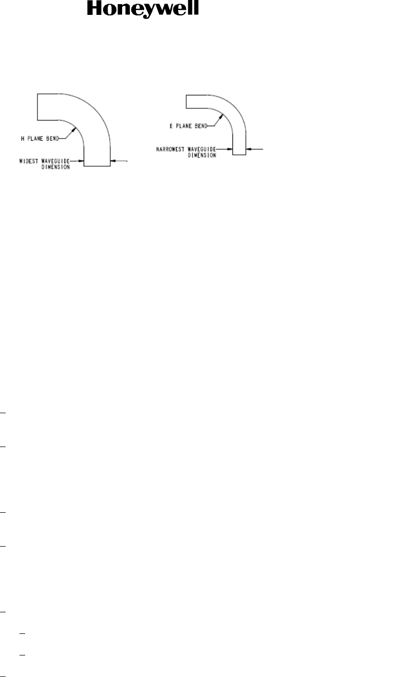
Page 2-19
16 Sep 2015
23-15-29
SYSTEM DESCRIPTION AND INSTALLATION MANUAL
JetWave™ System
© Honeywell International Inc. Do not copy without express permission of Honeywell.
Figure 2-8. View of H Plane and E Plane Bends
(5) Connecting the TMA interface, KRFU Power, and Control Interface
Power and control signals for the TMA assembly is supplied from the KANDU and is
connected to TMA J2 receptacle. Install location of KANDU is airframe specific. KANDU
could be installed in unpressurized area near the tail empennage of the aircraft or inside
pressurized area of the aircraft. In case of KANDU install location is inside pressurized
location, the KANDU to KRFU and KANDU to TMA interconnect may be routed through a
Bulkhead Interface connector.
Control signals for the KRFU is supplied from the KANDU and is connected to KRFU J2
receptacle. 115 VAC power supply for KRFU is supplied from aircraft power and is connected
to KRFU J1 receptacle. IF TX and IF RX signals to KRFU are supplied from Modman. Refer
to the TMA interconnection diagram Figure 2-33 for details.
(a) Remove the protective covers from the TMA J2 and KANDU J2 receptacles. Visually
inspect connectors and make sure that the pins are straight and not damaged.
1Clean the connectors with the contact cleaner and connect the cable assembly for
tail mount from KANDU J2 receptacle to TMA J2 receptacle.
2Make sure that the over braid of the cable assembly is terminated to connectors at
both TMA and KANDU ends.
(b) Remove the protective covers from the KRFU J2 and KANDU J3 receptacles. Visually
inspect connectors and make sure that the pins are straight and undamaged.
1Clean the connectors with the contact cleaner and connect the cable assembly for
tail mount from KANDU J3 receptacle to KRFU J2 receptacle.
2Make sure that the over braid of the cable assembly is terminated to connectors at
both KRFU and KANDU ends.
(c) Remove the protective covers from the KRFU J5 and KRFU J6 receptacles. Visually
inspect connector ends and make sure that there is no debris in central connector cavity.
1Clean the connectors with the contact cleaner before connecting.
aTX-IF connects from the Modman through the bulkhead J4B to KRFU J5.
bRX-IF connects from the Modman through the bulkhead J3B to KRFU J6.
2Make sure that the TX-IF coax cable is banded blue and RX-IF coax cable is
banded green at connector ends.
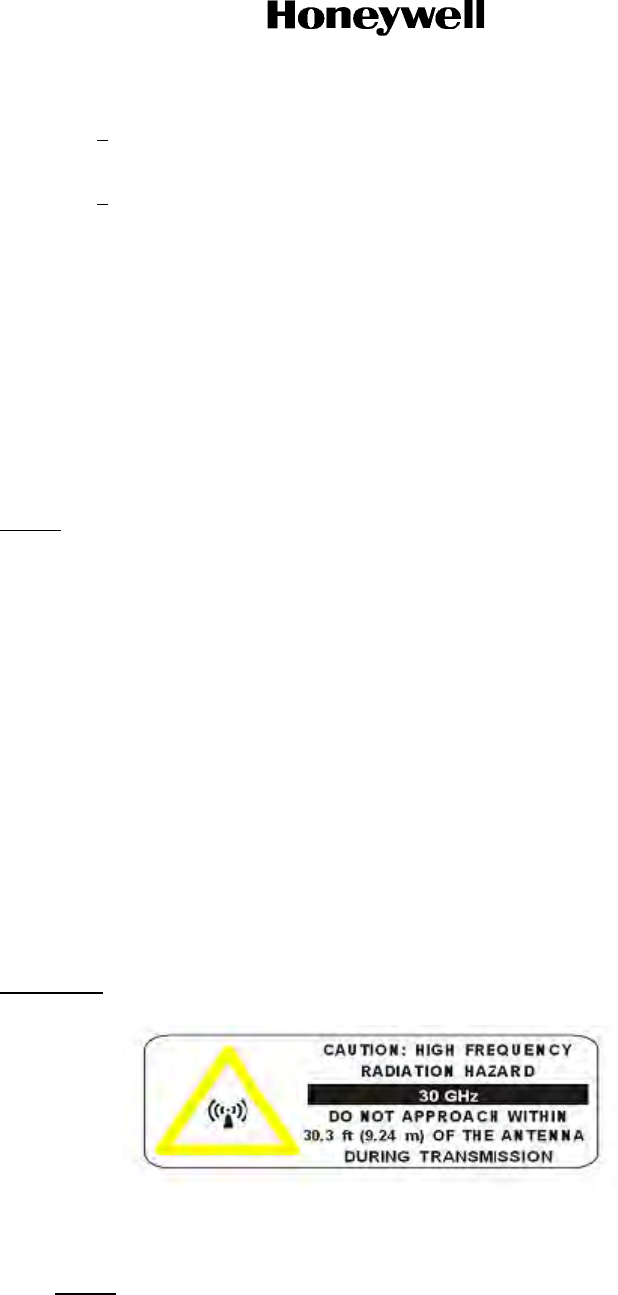
Page 2-20
16 Sep 2015
23-15-29
SYSTEM DESCRIPTION AND INSTALLATION MANUAL
JetWave™ System
© Honeywell International Inc. Do not copy without express permission of Honeywell.
3Make sure that the over braid of the cable assembly is terminated to connectors at
both KRFU and Modman or the bulkhead interface feed through ends.
4The over braid can be terminated to connector shield/housing or directly to housing.
(d) Make sure that all cable assembly routing are firmly held with wire clamps in accordance
with the airframe specific wiring diagram and there are no obstruction to the free
movement of tail mount antenna.
On completion of LRU interconnection and applying power to TMA, the tail mount antenna
will move in azimuth and elevation direction and move itself to its home position. The default
position is 0° in azimuth and 45° in elevation if the TMA is not talking to the rest of the system,
otherwise the default position is configured by a setting in the APM.
(6) Radome and Radome Fairing Installation with the TMA Interface Mount
Radome and fairing installation is aircraft specific. See aircraft specific SDIM for details.
NOTE: Before removing the Tail Mount Radome, Honeywell recommends manually steering the
TMA to a safe antenna orientation position using the JetWave™ GUI. The TMA parking
position is included in the AES System Configuration File and this can be accessed through
the GUI web interface and by navigating to Configuration File page.Consult aircraft specific
SDIM for detailed instructions.
K. TMA Alignment
On completion of physical installation of the TMA, the installed antenna system has to be aligned
and calibrated for any possible installation offsets. The antenna alignment for the JetWave™
system is designed to be performed automatically once initialized through a GUI interface.
It is recommended to do the antenna alignment calibration after initial installation and whenever the
OAE-TMA is removed and replaced. Only qualified avionics personnel who are knowledgeable in
the technical and safety issues related to the antenna systems should perform the alignment
procedures provided in this SDIMM.
Refer to Section 4.Q. for the TMA and FMA Antenna Alignment Procedure.
L. TMA Human Exposure to RF EM Fields
WARNING: THE JETWAVE™ SYSTEM IS A SOURCE OF NON-IONIZING RADIATION.
(1) The Minimum Safe Distance:
• TMA = 30.3 feet (9.24 m).
NOTE: The minimum safe distance for occupational/controlled exposure is determined
based on the computational method specified in FCC Office of Engineering and

Page 2-21
16 Sep 2015
23-15-29
SYSTEM DESCRIPTION AND INSTALLATION MANUAL
JetWave™ System
© Honeywell International Inc. Do not copy without express permission of Honeywell.
Technology; Bulletin Number 65, Edition 97-01: Evaluating compliance with FCC
Guidelines for human exposure to Radio Frequency Electromagnetic fields.
(2) The areas which the risk exists are based upon the location of the antenna. This means
personnel operating on the apron, transient personnel, and the general population in the
controlled exposure category will not be exposed to levels in excess of the limits.
Maintenance personnel working close to the tail must be protected by disabling the
transmitter before they approach that area of the aircraft.
(3) The JetWave™ system incorporates three fail-safe features to limit the potential for human
exposure to non-ionizing radiation:
(a) The system will not transmit unless the receiver is receiving a valid signal, therefore if
the received signal were to become blocked the transmitter would be disabled.
(b) The antenna subsystem includes a hardware end-stop that prevents the antenna
pointing more than two degrees below the horizontal.
(c) An input into the JetWave™ system wired on the aircraft to a switch in the aircraft, to
disable the RF transmission. This switch would be used to prevent any radiation from
the antenna in the event of aircraft operations in the vicinity of the antenna, for instance
when de-icing the aircraft. This would be achieved by a defined procedure on the
aircraft.
M. Fuselage Mount Antenna
(1) Introduction
The OAE FMA assembly will be installed on the top of the fuselage of the aircraft. For the
JetWave™ system to correctly point the antenna, the installation offsets should notexceed
more than 1 degree off heading, pitch or roll with respect to principle axis of aircraft.
Depending on the airframe, as part of the OAE FMA, the LRUs and assemblies that follow
will be installed outside aircraft:

Page 2-22
16 Sep 2015
23-15-29
SYSTEM DESCRIPTION AND INSTALLATION MANUAL
JetWave™ System
© Honeywell International Inc. Do not copy without express permission of Honeywell.
•FMA LRU
• KRFU LRU (if installed outside aircraft)
• Radome assembly
• A791 based AIM or the LAIM
• Radome skirt fairing.
The exact install location of the A791 based AIM or LAIM and KRFU is airframe specific.
The KRFU can be installed on the inside or outside the fuselage of the aircraft. Honeywell
recommends to install the KRFU on the A791 based AIM or LAIM outside the fuselage of the
aircraft.
The radome, skirt fairing, and FMA/KRFU to aircraft interface brackets are airframe specific
and said details are not covered by this manual.
NOTE: The A791 based AIM and the LAIM solutions differ in that the AIM is intended to be
broadly applicable accross all airframes. The LAIM, however refers to a solution that
would be designed specifically for the exact airframe that the JetWave™ system is
installed on. The LAIM solution will vary between airframes, in some cases by a large
amount. All specific figures and references to the LAIM that are included in this
manual are only an example of generic LAIM solutions. The user must not infer
applicability or design direction for the LAIM from any related material presented
herin.
Refer to the FMA outline and installation drawing in Figure 2-31, the KRFU outline and installation
drawings in Figure 2-27, Figure 2-28, and Figure 2-29, and the radome outline and installation
drawing in Figure 2-32. Depending on the aricraft configuration, refer to the interconnect diagrams
in Figure 2-34 for the KRFU installed inside the fuselage, Figure 2-35, or Figure 2-36 for external
KRFU.
Refer to Table 2-6 for special tools, fixtures, and equipment for the FMA installation.
(2) The FMA Installation General
Before installing any components or cabling, read all notes on drawings and read all
installation procedures.
(3) Advisories
The JetWave™ FMA and the KRFU subsystems include components that radiate RF and
microwave emissions in the band between 29.0 and 30.0 GHz.
All service technicians and operators must be informed of the potential hazards of RF and
microwave radiation. When installing and servicing equipment, exercise the safety
precautions that follow.
Table 2-6. Special Tools for FMA Installation
Number Description Source
NA Hoist system Commercially available

Page 2-23
16 Sep 2015
23-15-29
SYSTEM DESCRIPTION AND INSTALLATION MANUAL
JetWave™ System
© Honeywell International Inc. Do not copy without express permission of Honeywell.
WARNING: THIS EQUIPMENT RADIATES HIGH FREQUENCY RADIATION AND POSES A
RADIATION HAZARD. CONSIDERING THE WORST CASE CONDITION OF 100
PERCENT REFLECTION FOR THE FUSELAGE MOUNT ANTENNA,
HONEYWELL DEEMS IT NECESSARY TO ASSURE OEM FUSELAGE
ATTENUATION EXCEEDS 21.03 dB FOR FUSELAGE MOUNTED ANTENNAS
SYSTEM INSTALLATION. THIS IS THE MINIMUM ATTENUATION REQUIRED
FROM THE AIRCRAFT FUSELAGE TO ATTENUATE THE KA-BAND RADIATION
TO MEET A SAFE HUMAN EXPOSURE OF 1 MW/CM2 INSIDE THE AIRCRAFT.
WARNING: SERVICE TECHNICIANS AND OPERATORS MUST EXERCISE CARE TO KEEP
CLEAR OF THE ANTENNA’S BEAM WHILE PERFORMING OPERATIONAL
TESTS OR INSTALLATION VERIFICATION PROCEDURES. DO NOT
APPROACH WITHIN 66.6 FEET (20.3 METERS) OF THE FUSELAGE MOUNTED
ANTENNA ASSEMBLY DURING RADIO FREQUENCY TRANSMISSION.
WARNING: DURING ANTENNA OPERATION (TRANSMISSION), MAKE SURE THAT
MINIMIZE THE EXPOSURE OF ALL PERSONNEL TO ANY REFLECTED,
SCATTERED, OR DIRECT BEAMS.
CAUTION: SERVICE TECHNICIANS MUST OBEY STANDARD SAFETY PRECAUTIONS,
SUCH AS WEARING SAFETY GLASSES, TO PREVENT PERSONAL INJURY
WHILE INSTALLING OR PERFORMING SERVICE ON THIS UNIT.
CAUTION: THE FUSELAGE MOUNT OAE ASSEMBLY IS ELECTROSTATIC-SENSITIVE.
STANDARD ELECTROSTATIC-SENSITIVE HANDLING PROCEDURES MUST BE
OBSERVED.
(4) Unpacking and Inspection
This section describes how to make sure that the equipment is in good condition after
shipping. To unpack and inspect the equipment do as follows:
(a) Unpack the equipment components from the shipping container.
(b) Make sure that all components of the fuselage mount OAE subsystem as indicated on
the parts list / bill of materials are included.
(c) Visually examine the units for any shipping damage.
(5) FMA Installation Kits
Other than the parts list specified in Table 2-7, the installation kit for the A791 based AIM or
the LAIM, waveguide and coax assemblies, wiring assemblies, brackets, clamps, and
mounting assembly will be airframe specific. Refer to airframe specific wiring diagram for
details. The radome skirt fairing will be airframe specific. The LAIM will be a custom solution
for a particular airframe.
Table 2-7. FMA installation Kits
PN Description
SCD-90402677 WR42 to 2.92 mm coax adapter

Page 2-24
16 Sep 2015
23-15-29
SYSTEM DESCRIPTION AND INSTALLATION MANUAL
JetWave™ System
© Honeywell International Inc. Do not copy without express permission of Honeywell.
(6) Airframe Structural Modifications
For the installation of OAE-FMA, structural modifications to the airframe may be required in
the region where the OAE-FMA is to be mounted to accommodate the additional mass of the
antenna assembly and resulting aerodynamic loads.
The aerodynamic loads are dependent on the aircraft type as well as the installation location
of the OAE-FMA on the aircraft, and are therefore installation specific.
Bird strike and rapid decompression need to be considered for analysis and structural
substantiation.
The appropriately qualified personnel should derive the loads and do a structural analysis to
make sure of the suitability of the modifications.
The installer is responsible for all structural modifications to the aircraft.
(7) Mounting Guidelines
This section describes the mounting guidelines for fuselage mount OAE.
Physical Placement:
The aircraft fuselage mount OAE is installed on top of the fuselage for clear satellite
communications.
Figure 2-9 shows a typical installation location for the fuselage mount OAE on an aircraft.
Honeywell recommends not installing the FMA at the mid fuselage station location of the
aircraft near the wings or slightly aft of the wings.
90404243 RF component kit (KRFU to FMA waveguide
and RX coax cable FMA to KRFU)
Table 2-7. FMA installation Kits(Cont)
PN Description
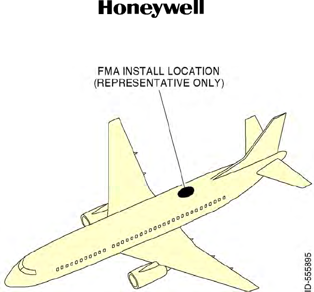
Page 2-25
16 Sep 2015
23-15-29
SYSTEM DESCRIPTION AND INSTALLATION MANUAL
JetWave™ System
© Honeywell International Inc. Do not copy without express permission of Honeywell.
Figure 2-9. FMA Install Location
The fuselage antenna assembly and KRFU (if installed outside the aircraft) will be mounted
on the antenna interface mount and it suplies a means to secure all equipment and wiring
mounted on it.
Depending on the airframe, the A791 based AIM or LAIM is installed to provide a firm flat
base for installation of the FMA and KRFU. These are detailed in the next sections.
(8) Installation Guidelines for the A791 Based AIM
The skirt fairing comes attached to the ARINC 791 based AIM plate. The installation
sequence suggested for mounting A791 based AIM is as follows:
•Install the A791 based AIM bonding straps.
• Install the A791 based AIM fittings to the aircraft fuselage.
• Mount the A791 based AIM.
• Install the A791 based AIM bonding straps to the A791 based AIM assembly.
Before putting the A791 based AIM assembly onto aircraft, install bonding straps to the
aircraft fittings. Refer to the airframe specific kits and assembly drawings for fastener details.
Figure 2-10 shows a typical ground strap connection.
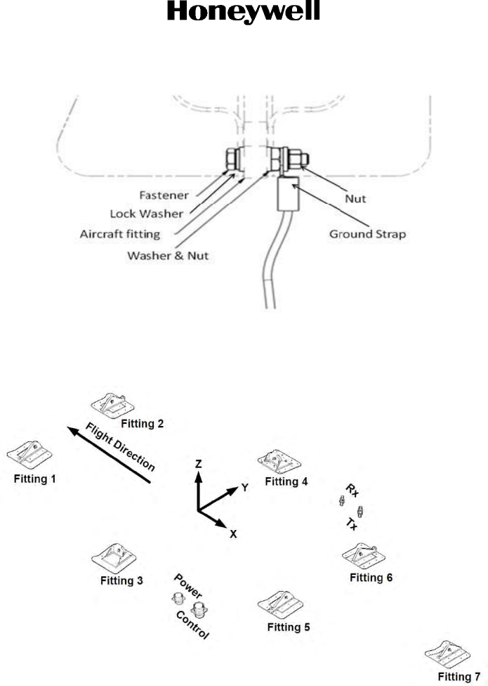
Page 2-26
16 Sep 2015
23-15-29
SYSTEM DESCRIPTION AND INSTALLATION MANUAL
JetWave™ System
© Honeywell International Inc. Do not copy without express permission of Honeywell.
Figure 2-10. Typical Ground Strap Arrangement for A791 Compliant Fittings
The aircraft coordinate system orientation and fitting layout are shown in Figure 2-11.
Figure 2-11. Aircraft Coordinate System Orientation and Fitting Layout
(a) Position and install the A791 based AIM fittings onto aircraft fittings for fittings #1, #2,
#5, #6, and #7.
(b) Use the alignment tools to make sure that the fitting slip in X-direction is centered for
fittings #2, #6, and #7.
(c) Make sure that all the fittings are oriented vertically with the alignment tools to help when
you lower the A791 based AIM onto aircraft fittings and the installed fittings pass through
openings in A791 based AIM.
(d) Put the A791 based AIM assembly onto aircraft with an aircraft servicing hoist. Attach
the hoist to the A791 based AIM adapter plate at three locations labeled “Hoist Point”.
Make sure that the previously installed fittings on aircraft are still oriented vertically so
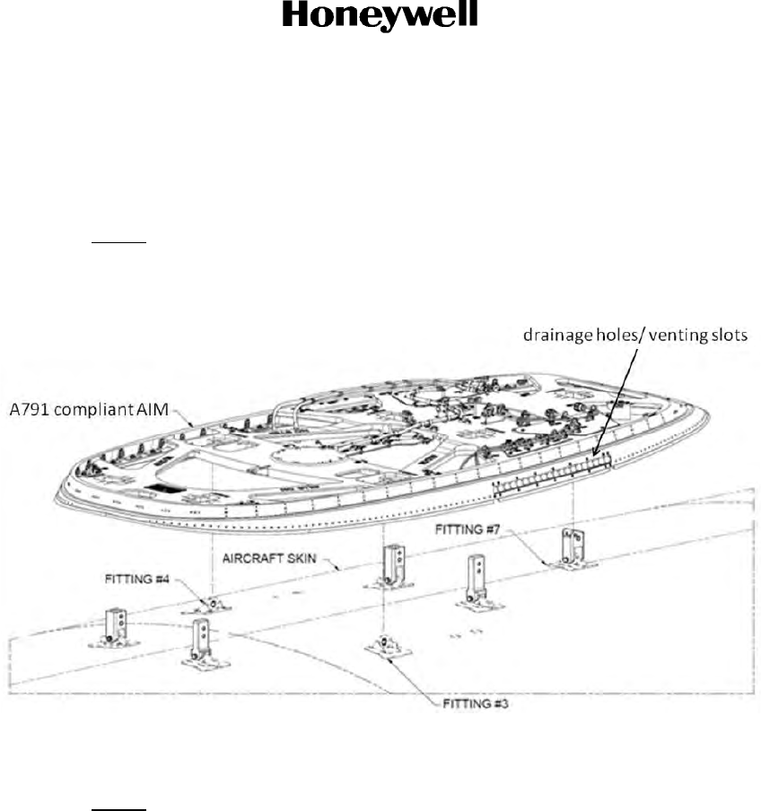
Page 2-27
16 Sep 2015
23-15-29
SYSTEM DESCRIPTION AND INSTALLATION MANUAL
JetWave™ System
© Honeywell International Inc. Do not copy without express permission of Honeywell.
that they will pass through the openings in the adapter plate as AIM assembly is lowered
onto aircraft. Refer to Figure 2-12.
(e) Refer to the airframe specific kits and assembly for fastener specifications to install A791
complaint AIM fittings to aircraft fittings.
NOTE: Consult airframe manufacturer for choosing the correct torque values.
(f) Wet the fuselage skin with water on skirt seal contact area before you put the AIM
assembly on aircraft.
Figure 2-12. AIM Assembly Placement on Aircraft
(9) Installation Guidelines for the LAIM
NOTE: The LAIM is custom designed to the aircraft they will be installed on.
The installation sequence suggested for mounting the LAIM is as follows:
• Install the LAIM and radome shirt fairing bonding straps.
• Install the LAIM to the aircraft fuselage.
• Install the radome skirt fairing.
Install the LAIM and Radome Shirt Bonding Straps
(a) Before mounting the LAIM assembly onto the aircraft, install bonding straps to aircraft
fittings. There are eight bonding straps. Six of the bonding straps are installed between
the bonding points and the radome skirt fairing. Two bonding straps are installed
between the bonding points and the LAIM structure.
(b) Refer to the airframe specific kits and assembly drawings for fastener details.
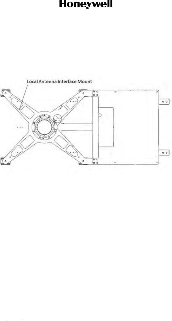
Page 2-28
16 Sep 2015
23-15-29
SYSTEM DESCRIPTION AND INSTALLATION MANUAL
JetWave™ System
© Honeywell International Inc. Do not copy without express permission of Honeywell.
Install the LAIM to the Aircraft Fuselage
(a) Make sure that all the fittings are oriented vertically with the alignment tools, to help
when you lower the LAIM onto aircraft fittings.
(b) Put the LAIM assembly onto aircraft install location. Refer to Figure 2-13 for a generic
LAIM installation on airframe structure.
Figure 2-13. LAIM Assembly
(c) The LAIM gets attached to aircraft structure at six machined fitting locations. Forward
four fittings each have four attachment points, through the aircraft skin to the
intercostals. The two aft fittings each have four attachment points through aircraft skin
to the stringer rivet hole locations. Machined brackets will get attached to intercostals
with fasteners.
Refer to the airframe specific kits and assembly for fastener specifications to install LAIM
to aircraft.
Install the Radome Skirt Fairing
(a) Before mounting the radome skirt fairing assembly onto aircraft, make sure that all the
fittings are oriented vertically with the alignment tools, to help when you lower the
radome skirt fairing assembly onto the aircraft fittings.
(b) Put the radome skirt fairing assembly onto the aircraft. Refer to the airframe specific kits
and assembly for fastener specifications to install radome skirt fairing assembly to
aircraft. Figure 2-14 shows the radome skirt assembly along with LAIM.
(c) The radome skirt fairing assembly is mounted firmly with 39 fastener points through
aircraft skin into gusset attached to the outer flange of the intercostals and into gusset
attached to the inner flange of the intercostals (1 at the forward center and 19 on each
side).
NOTE: Consult airframe manufacturer for choosing the correct torque values.
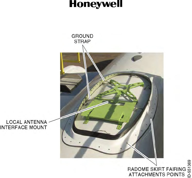
Page 2-29
16 Sep 2015
23-15-29
SYSTEM DESCRIPTION AND INSTALLATION MANUAL
JetWave™ System
© Honeywell International Inc. Do not copy without express permission of Honeywell.
Figure 2-14. Radome Skirt Fairing and LAIM Assembly Position on Aircraft
(10) FMA Bonding
The bonding straps are installed before proceeding with installation of FMA assembly on the
A791 based AIM or LAIM.
The FMA assembly and KRFU must be bonded to the airframe.
Consult the airframe manufacturer for the correct torque values.
N. FMA Installation Procedure
Following installation activities are detailed in subsequent sections:
• Installation of the FMA.
• Connecting the waveguide, RF coax interface to the FMA.
• Installation of KRFU and bonding straps.
• Installation of waveguide and coax between FMA and KRFU.
• Connecting Bulkhead Interface, KRFU power and control interfaces.
• Position and installation of radome.
(1) Installation of the FMA Assembly

Page 2-30
16 Sep 2015
23-15-29
SYSTEM DESCRIPTION AND INSTALLATION MANUAL
JetWave™ System
© Honeywell International Inc. Do not copy without express permission of Honeywell.
(a) Align the FMA assembly above adapter plate with an aircraft service hoist. Attach hoist
to the FMA lifting fixture at two locations on each side of fixture. Refer to Figure 2-15.
Figure 2-15. FMA Assembly
(b) Put the FMA onto the FMA mounting holes with alignment pins and make sure that the
waveguide flange is pointed to the rear of the AIM. Make sure that the pigtails do not
interfere to avoid damage.
(c) Remove the FMA lifting fixture. Refer to Figure 2-16.

Page 2-31
16 Sep 2015
23-15-29
SYSTEM DESCRIPTION AND INSTALLATION MANUAL
JetWave™ System
© Honeywell International Inc. Do not copy without express permission of Honeywell.
Figure 2-16. FMA Assembly Lifting Fixture Removal
(d) The orientation of the FMA assembly is defined with respect to the principal axes of the
aircraft.
(e) Attach the FMA to the AIM with screws and flat washers. The AIM is provisioned with
captive nuts. Refer to the airframe specific kits and assembly for fastener specifications
and required torque. Mounting holes in base are accessed from the top between the
antenna and turntable by rotating the assembly in azimuth.
(f) Remove protective cap from disconnect plug on harness.
1Visually inspect connector and make sure that there are no debris in cavities.
2Visually inspect the center conductor and verify that it is still straight and the finish
is intact.
(2) FMA Bonding Requirements
(a) Install one end of bonding straps to AIM at labeled bonding points with screw and
washers.
(b) Install the other end of bonding straps to bonding points on the FMA base. Refer to the
airframe specific kits and assembly for fastener specifications and required torque.
Refer to Figure 2-10 for the FMA ground strap connection.
(3) Waveguide and RF Coax Interconnection to FMA Assembly
(a) Waveguide and RF coax interconnect designs are aircraft specific. Consult aircraft
specific SDIM for detailed installation instructions.
(b) Remove protective cap on FMA J4 (2.92 mm female coax) and FMA J3. Connect K-type
disconnect plug to K-type disconnect receptacle J4 on the FMA. Connect the WR34
waveguide assembly to the FMA receptacle J3
(4) KRFU Installation Location
(a) The KRFU install location is airframe specific.
(b) The KRFU can be installed inside the aircraft or external to the aircraft under the
radome. Honeywell recommends that the KRFU is installed external to the aircraft,
under the radome.
(c) When the KRFU is installed under the radome the conduction cooled variant must be
used. This variant achieves cooling through its base plate and must be installed with the
provided thermal pad to ensure a good thermal path between the KRFU and the AIM or
LAIM. Refer to KRFU Thermal Pad Kit installation Section 4.F., before you install the
KRFU LRU.
(d) When the KRFU is installed inside the aircraft either the conduction cooled or forced air
cooled variant may be used.
(e) The KRFU must be installed close to fuselage mount antenna assembly so as to
minimize the waveguide/coax RF losses on the RF interconnect.

Page 2-32
16 Sep 2015
23-15-29
SYSTEM DESCRIPTION AND INSTALLATION MANUAL
JetWave™ System
© Honeywell International Inc. Do not copy without express permission of Honeywell.
(f) It is recommended to use flexible waveguide / Coax RF interface with interconnect
losses not to exceed 1.5 dB on the transmit path and 2.9 dB on the receive path between
the KRFU and FMA assembly. Honeywell has developed a RF component kit
(90404243) containing a suitable waveguide and coaxial cable.
(5) KRFU Installation
Refer to Section 4.K.(3). KRFU Installation procedure.
(6) Installation of the Waveguide and Coax Interconnect Between the FMA and Externally
Mounted KRFU
(a) Loosely attach the waveguide and coax support brackets to the AIM. The flexible wave
guide and coax cable assembly kit and its routing are aircraft specific.
(b) Remove the protective covers from the FMA J3 RF TX. Visually examine connector
ends and make sure that there is no debris in the cavities.
(c) Loosely connect the WR34 flexible waveguide to the FMA J3 waveguide flange with
sealing gasket. Hand tighten the fasteners.
(d) Loosely attach the waveguide and coax support brackets to the AIM.
(e) Loosely connect the WR34 to WR28 waveguide adapter to the KRFU with sealing
gasket. Apply torque to the waveguide adapter flange for all fasteners as recommended.
(f) Loosely connect the waveguide assembly to the KRFU with a sealing gasket.
(g) Apply torque to the KRFU waveguide flange for all fasteners as recommended.
(h) Firmly attach waveguide support brackets to adapter plate.
The minimum allowable bend radius to the center line for flexible waveguide is 1 inch (25.4
mm) in H plane (bend along the long axis of the waveguide) and 0.5 inch (12.7 mm) in E plane
(bend along the short axis of the waveguide). The minimum allowable bend radius for the
coax cable is 0.25 inch (6.35 mm). Refer to Figure 2-17.
Figure 2-17. View of H Plane and E Plane Bends
(7) Connecting the FMA Interface, KRFU Power, and Control Interfaces
The control signals for the KRFU are supplied from the KANDU and are connected to KRFU
J2 receptacle.
The 115 VAC power supply for the KRFU is supplied from the aircraft power and is connected
to KRFU J1 receptacle.

Page 2-33
16 Sep 2015
23-15-29
SYSTEM DESCRIPTION AND INSTALLATION MANUAL
JetWave™ System
© Honeywell International Inc. Do not copy without express permission of Honeywell.
The IF TX and IF RX signals to KRFU are supplied from the Modman. These are routed
through bulkhead interface. Refer to the appropriate FMA interconnection diagram Figure
2-34, Figure 2-35, or Figure 2-36 for details.
(a) Remove the protective covers from the FMA P2 and KANDU J2 receptacles. Visually
examine the connectors and make sure that the pins are straight and undamaged.
1Clean the connectors with the contact cleaner and connect the cable assembly for
fuselage mount from the KANDU J2 receptacle to the FMA P1, P2, and P3
receptacles.
2Make sure that the over braid of the cable assembly is terminated to connectors at
both the FMA and KANDU ends.
(b) Remove the protective covers from the KRFU J2 and KANDU J3 receptacles. Visually
examine the connectors and make sure that the pins are straight and undamaged.
1Clean the connectors with the contact cleaner and connect the cable assembly for
fuselage mount from the KANDU J3 receptacle to the KRFU J2 receptacle.
2Make sure that the over braid of the cable assembly is terminated to connectors at
both the KRFU and KANDU ends.
(c) Remove the protective covers from the KRFU J5 and KRFU J6 receptacles. Visually
examine the connector ends and ensure there is no debris in central connector cavity.
1Clean the connectors with the contact cleaner before connecting.
2Make sure that the TX-IF coax cable is banded blue and RX-IF coax cable is
banded green at connector ends.
3Make sure that the over braid of the cable assembly is terminated to connectors at
both the KRFU and bulkhead interface feed through ends.
4The over braid can be terminated to the connector shield/housing or directly to the
housing.
(d) Make sure that all the cable assembly routing are firmly held with wire clamps in
accordance with the airframe specific wiring diagram and there are no obstruction to the
free movement of the FMA. Refer to Figure 2-18 for the A791 based AIM and Figure
2-18 for the LAIM.
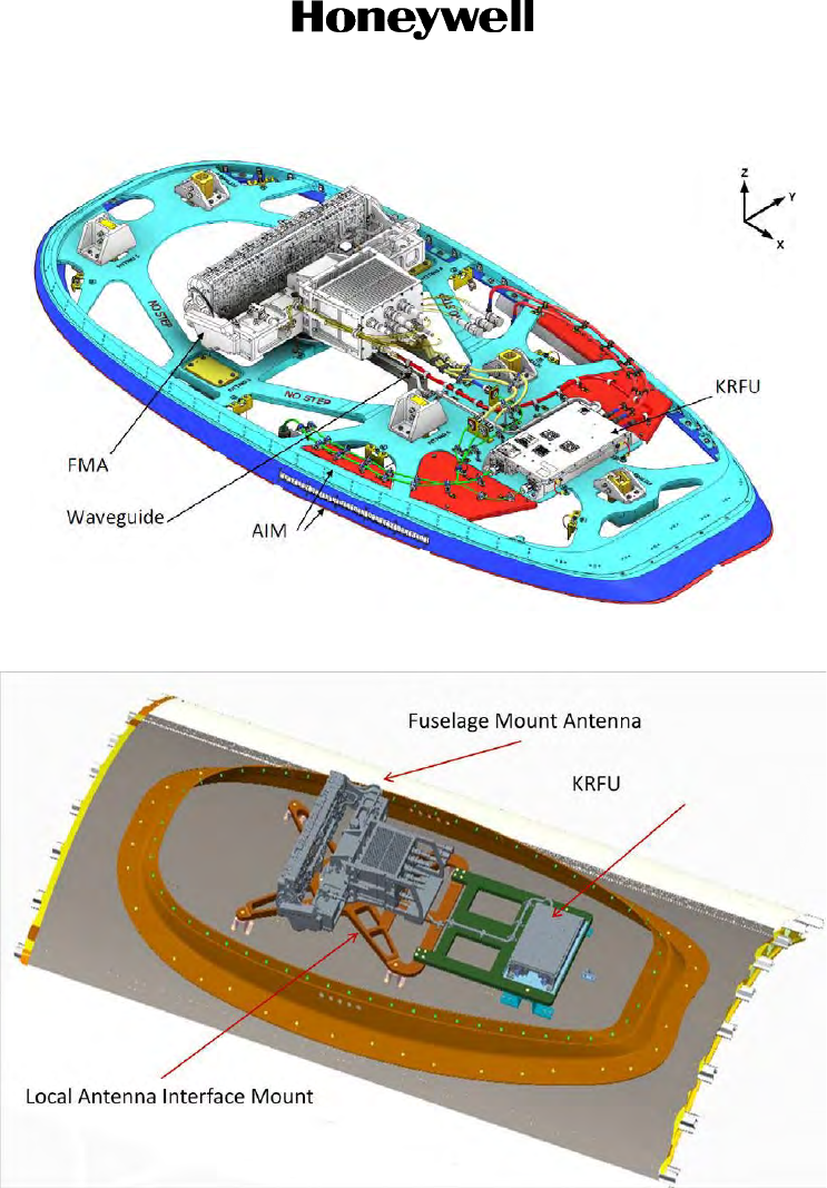
Page 2-34
16 Sep 2015
23-15-29
SYSTEM DESCRIPTION AND INSTALLATION MANUAL
JetWave™ System
© Honeywell International Inc. Do not copy without express permission of Honeywell.
Figure 2-18. A791 Based AIM Assembly with FMA and KRFU Placement on Aircraft
Figure 2-19. LAIM Assembly with FMA and KRFU Placement on Aircraft
On completion of the LRU interconnection and applying power to the FMA, the FMA will stay
in its current position until it is told to move by the KANDU.
(8) AIM/LAIM Radome Installation
The radome installation is aircraft specific. See aircraft specific SDIM for details.
Depending on the AIM selected, the radome gets installed differently.
With the A791 based AIM, the Radome will be installed on the A791 based AIM.
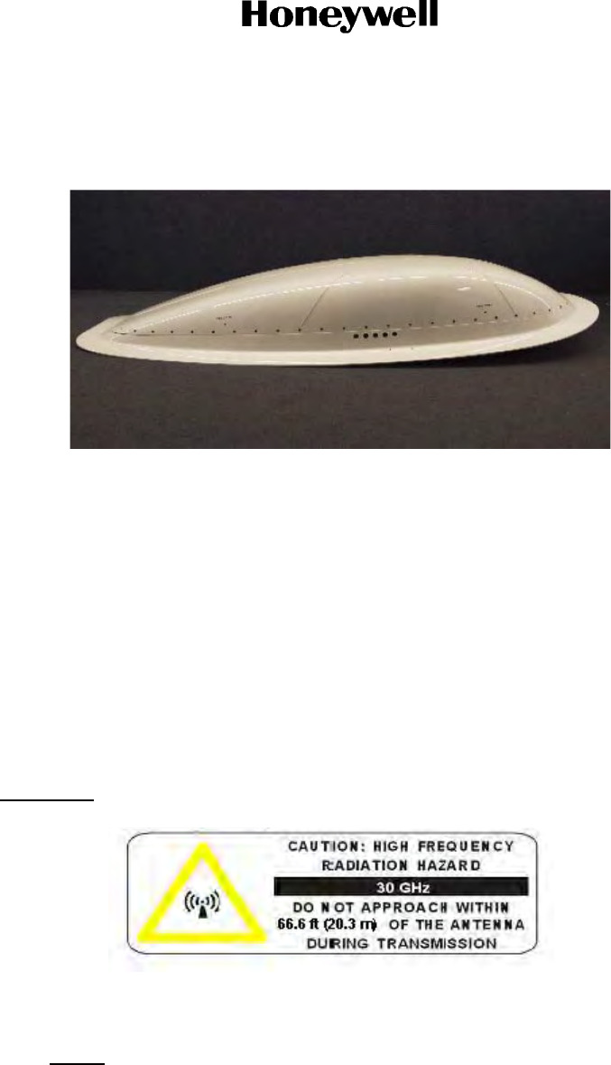
Page 2-35
16 Sep 2015
23-15-29
SYSTEM DESCRIPTION AND INSTALLATION MANUAL
JetWave™ System
© Honeywell International Inc. Do not copy without express permission of Honeywell.
With the LAIM, the radome will be installed on the Radome skirt fairing assembly. Refer to
the and Figure 2-20.
Figure 2-20. Radome Assembly Mounted on Radome Skirt Fairing (LAIM)
O. FMA Alignment
On completion of physical installation of the FMA, the installed antenna system has to be aligned
and calibrated for any possible installation offsets. The antenna alignment for the JetWave™
system is designed to be performed automatically once initialized through a GUI interface.
It is recommended to do the antenna alignment calibration after initial installation and whenever the
OAE-FMA is removed and replaced. Only qualified avionics personnel who are knowledgeable in
the technical and safety issues related to the antenna systems should do the alignment procedures
provided in this SDIMM.
Refer to Section 4.Q. TMA and FMA Antenna Alignment Procedure.
P. FMA Human Exposure to RF EM Fields
WARNING: THE JETWAVE™ SYSTEM IS A SOURCE OF NON-IONIZING RADIATION.
(1) The Minimum Safe Distance:
• FMA = 66.6 feet (20.3 m).
NOTE: The minimum safe distance for occupational/controlled exposure is determined
based on the computational method specified in FCC Office of Engineering and
Technology; Bulletin Number 65, Edition 97-01: Evaluating compliance with FCC
Guidelines for human exposure to Radio Frequency Electromagnetic fields.

Page 2-36
16 Sep 2015
23-15-29
SYSTEM DESCRIPTION AND INSTALLATION MANUAL
JetWave™ System
© Honeywell International Inc. Do not copy without express permission of Honeywell.
(2) The areas which the risk exists are based upon the location of the antenna. This means
personnel operating on the apron, transient personnel, and the general population in the
controlled exposure category will not be exposed to levels in excess of the limits.
Maintenance personnel working close to the tail must be protected by disabling the
transmitter before they approach that area of the aircraft.
(3) The JetWave™ system incorporates three fail-safe features to limit the potential for human
exposure to non-ionizing radiation:
(a) The system will not transmit unless the receiver is receiving a valid signal, therefore if
the received signal were to become blocked the transmitter would be disabled.
(b) The antenna subsystem includes a hardware end-stop that prevents the antenna from
pointing more than two degrees below its mounting plane.
(c) An input into the JetWave™ system wired on the aircraft to a switch in the aircraft, to
disable the RF transmission. This switch would be used to prevent any radiation from
the antenna in the event of aircraft operations in the vicinity of the antenna, for instance
when de-icing the aircraft. This would be achieved by a defined procedure on the
aircraft.
Q. TMA and FMA Antenna Alignment Procedure
(1) Antenna Assembly Orientation
For the JetWave™ system to point to the servicing satellite correctly, it is important to align
the antenna assembly after installation. The TMA/FMA assembly has a built in IMU and its
orientation must be aligned with respect to the principal axes of the aircraft which is
determined through aircraft IRS.
(a) To do the automatic antenna alignment calibration, aircraft should have a functional IRS,
interfaced with the KANDU through A429 interface, and should have the required
ARINC 429 labels as defined in the APM configuration file.
(b) During the physical installation, the IMU principal axes of the TMA/FMA is aligned with
those of the aircraft within ± 1° on the pitch, roll, and yaw axis. The installation offsets,
are then estimated by the KANDU automatically from data received from the aircraft
Inertial Navigational System and the TMA/FMA IMU assembly.
(c) It is recommended to do the automatic antenna alignment calibration with the Radome
installed. The antenna alignment process can be initiated through the GUI interface. The
JetWave™ system GUI service is supported on AV1 and AG1 10/100 Base T Ethernet
interfaces. Modman static IP assigned is 172.29.55.1 and the port number for the AES
GUI service is 80.
(2) Automatic Antenna Alignment GUI Interface
The JetWave™ system GUI service is supported on AV1 and AG1 10/100 Base T Ethernet
interfaces. Modman static IP assigned is 172.29.55.1 and the port number for the AES GUI
service is 80.
(a) On any Internet browser (Internet Explorer 8 compatible), open the link "index.html". The
Login page appears. Figure 2-21 shows the Login page.
Page 2-37
16 Sep 2015
23-15-29
SYSTEM DESCRIPTION AND INSTALLATION MANUAL
JetWave™ System
© Honeywell International Inc. Do not copy without express permission of Honeywell.
Figure 2-21. GUI Login Page
(b) Enter the username and password below to access the maintenance interface.
• Username: "Maintenance" and Password: "Earthbound".
(3) Positioning of Aircraft for Antenna Alignment
(a) On the GUI Calibrate Antenna Alignment page, as shown in Figure 2-22, the current
location of aircraft in terms of latitude and longitude is indicated along with the longitude
of the servicing Geo stationary satellite.

Page 2-38
16 Sep 2015
23-15-29
SYSTEM DESCRIPTION AND INSTALLATION MANUAL
JetWave™ System
© Honeywell International Inc. Do not copy without express permission of Honeywell.
Figure 2-22. GUI Calibrate Antenna Alignment Page
(b) For the automatic antenna alignment calibration, it is recommended to tow and put the
aircraft in an open area away from aircraft hangers such that there is clear visibility to
the open sky with the heading of the aircraft pointed in one of four recommended aircraft
heading values displayed on the GUI antenna calibration page.
(c) The automatic antenna alignment calibration can be carried out at up to four different
aircraft headings. Out of the available headings, it is required to do only one automatic
alignment calibration while the aircraft heading is toward one of the preferred directions.
(d) The recommended values are dependent on the radome and these values are
estimated by the KANDU based on the input from the aircraft IRS and the selected
satellite coordinates.
NOTE: It is advised not to do the automatic antenna alignment during rains with heavily
clouded sky.
(4) Automatic Antenna Alignment
The JetWave™ system uses the following input parameters during the antenna alignment
procedure:
• Aircraft IRS data
• OAE IMU data

Page 2-39
16 Sep 2015
23-15-29
SYSTEM DESCRIPTION AND INSTALLATION MANUAL
JetWave™ System
© Honeywell International Inc. Do not copy without express permission of Honeywell.
• RSSI as reported from the Modman.
(a) The GUI page indicates the status of the aircraft. In order to proceed with the antenna
calibration process, all LRUs of the JetWave™ system need to be powered up with
aircraft IRS system functioning and providing valid inputs. The GUI page indicates the
IRS status.
(b) Once the aircraft is aligned to within ± 5 degrees of any of the recommended aircraft
heading, the grayed out on the “Initiate” button will be changed, indicating the system
readiness to commence the antenna alignment process.
(c) The GUI Antenna Alignment Calibration progress status bar is shown in Figure 2-23.
(d) On successful completion of the antenna calibration, the statues changes to "Aligned".
Figure 2-23. GUI Antenna Alignment Calibration Page Extract
5. Electrical Installation
For details about electrical installation, refer to Figure 2-33 thru Figure 2-36 for the system interconnect
diagrams.
6. Cabling Requirements
Refer to Table 2-8 for the cabling requirements.

Page 2-40
16 Sep 2015
23-15-29
SYSTEM DESCRIPTION AND INSTALLATION MANUAL
JetWave™ System
© Honeywell International Inc. Do not copy without express permission of Honeywell.
When installing the JetWave™ system, follow the cabling requirements listed below:
• Ethernet LAN/WAN cables must meet flammability and TIA/EIA568-A CAT 5E requirements.
• Carlisle IT (ECS) 422404 or NF24Q100-01 is recommended for Quadrax connections.
• Twisted shielded pairs must meet ARINC 791 wiring requirements or equivalent.
Refer to Figure 2-33, Figure 2-34, Figure 2-35, and Figure 2-36 for wire size recommendations.
7. Drawings and Diagrams
Refer to Figure 2-24 for the Modman outline and installation drawing.
Refer to Figure 2-25 for the APM outline and installation drawing.
Refer to Figure 2-26 for the KANDU outline and installation drawing.
Refer to Figure 2-27 for the KRFU PN 90401203, conduction-cooled 1, outline and installation drawing.
Refer to Figure 2-28 for the KRFU PN 90402346, conduction-cooled 2, outline and installation drawing.
Refer to Figure 2-29 for the KRFU PN 90401202, forced air cooled, outline and installation drawing.
Refer to Figure 2-30 for the TMA outline and installation drawing.
Refer to Figure 2-31 for the FMA outline and installation drawing.
Refer to Figure 2-32 for the Fuselage Mount Radome outline and installation drawing.
Refer to Figure 2-33 for the JetWave™ System - TMA interconnect diagram.
Refer to Figure 2-34 for the JetWave™ System - FMA (baseline) interconnect diagram.
Refer to Figure 2-35 for the JetWave™ System - Boeing Specific FMA (external KRFU) interconnect
diagram.
Refer to Figure 2-36 for the JetWave™ System - A350 Specific FMA interconnect diagram.
Table 2-8. Cabling Requirements
Cable Conductor Type Single
Point Multiple
Point Minimum Conductor
Coverage by Shield
Power Lines Single conductor, stranded NA N/A N/A
Ethernet Data Quadrax, twister pair - Yes 100%
RF Coaxial, waveguide - Yes 100%
A429 Twisted pair, stranded - Yes 95%
RS-422 Twisted pair, shielded - Yes 100%
Discrete Twisted pair, shielded, KANDU
Single conductor, shielded, grounds Yes 100%
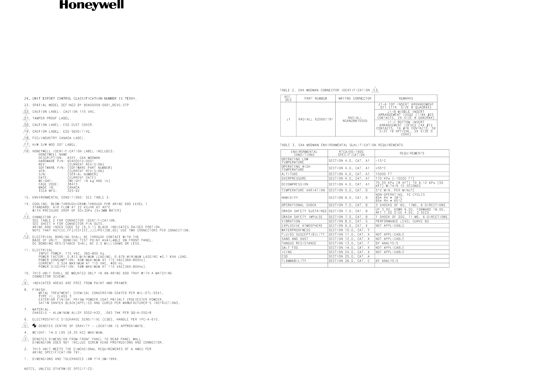
SYSTEM DESCRIPTION AND INSTALLATION MANUAL
JetWave™ System
Page 2-41
16 Sep 2015
© Honeywell International Inc. Do not copy without express permission of Honeywell.
23-15-29
Figure 2-24. Modman Outline and Installation Drawing (Sheet 1 of 4)
E90400059-0001-1-C

SYSTEM DESCRIPTION AND INSTALLATION MANUAL
JetWave™ System
Page 2-42
16 Sep 2015
© Honeywell International Inc. Do not copy without express permission of Honeywell.
23-15-29
Blank Page
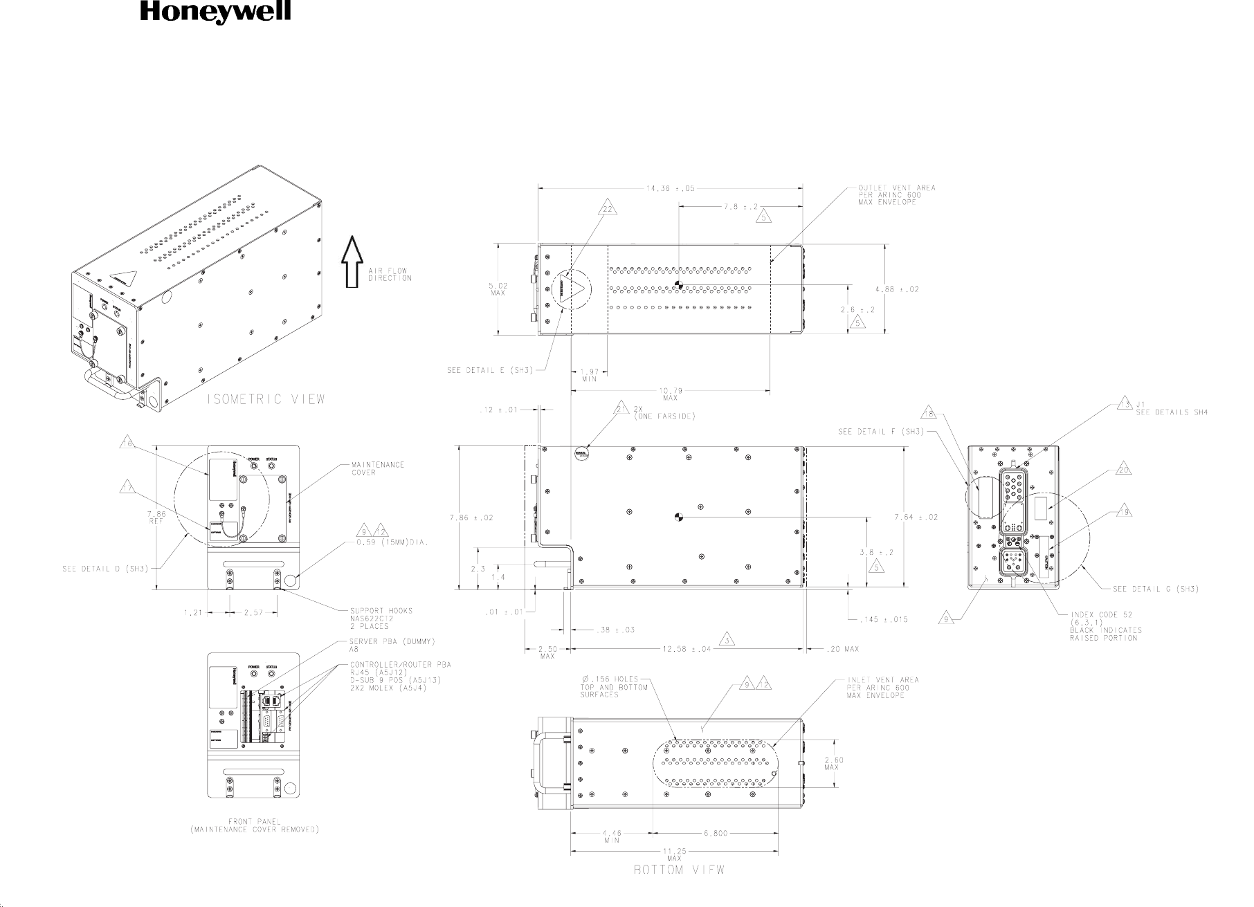
SYSTEM DESCRIPTION AND INSTALLATION MANUAL
JetWave™ System
Page 2-43
16 Sep 2015
© Honeywell International Inc. Do not copy without express permission of Honeywell.
23-15-29
Figure 2-24. Modman Outline and Installation Drawing (Sheet 2 of 4)
E90400059-0001-2-C

SYSTEM DESCRIPTION AND INSTALLATION MANUAL
JetWave™ System
Page 2-44
16 Sep 2015
© Honeywell International Inc. Do not copy without express permission of Honeywell.
23-15-29
Blank Page
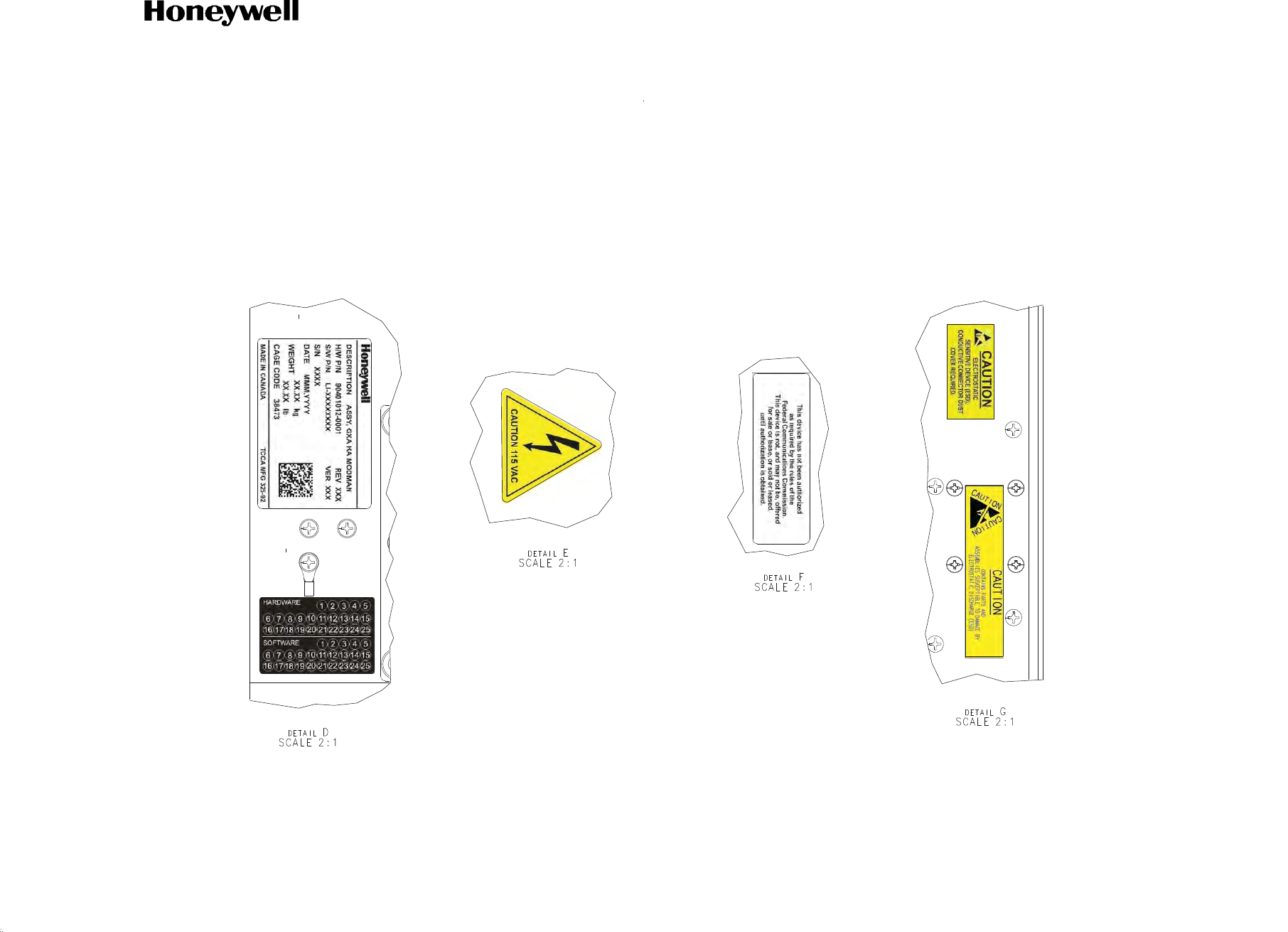
SYSTEM DESCRIPTION AND INSTALLATION MANUAL
JetWave™ System
Page 2-45
16 Sep 2015
© Honeywell International Inc. Do not copy without express permission of Honeywell.
23-15-29
Figure 2-24. Modman Outline and Installation Drawing (Sheet 3 of 4)
E90400059-0001-3-C

SYSTEM DESCRIPTION AND INSTALLATION MANUAL
JetWave™ System
Page 2-46
16 Sep 2015
© Honeywell International Inc. Do not copy without express permission of Honeywell.
23-15-29
Blank Page
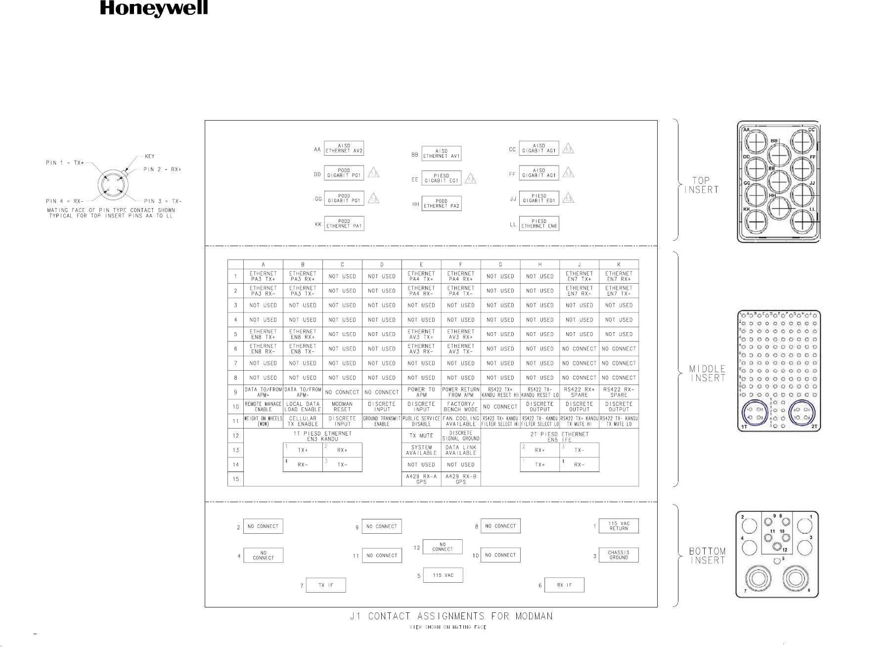
SYSTEM DESCRIPTION AND INSTALLATION MANUAL
JetWave™ System
Page 2-47
16 Sep 2015
© Honeywell International Inc. Do not copy without express permission of Honeywell.
23-15-29
Figure 2-24. Modman Outline and Installation Drawing (Sheet 4 of 4)
E90400059-0001-4-C

SYSTEM DESCRIPTION AND INSTALLATION MANUAL
JetWave™ System
Page 2-48
16 Sep 2015
© Honeywell International Inc. Do not copy without express permission of Honeywell.
23-15-29
Blank Page
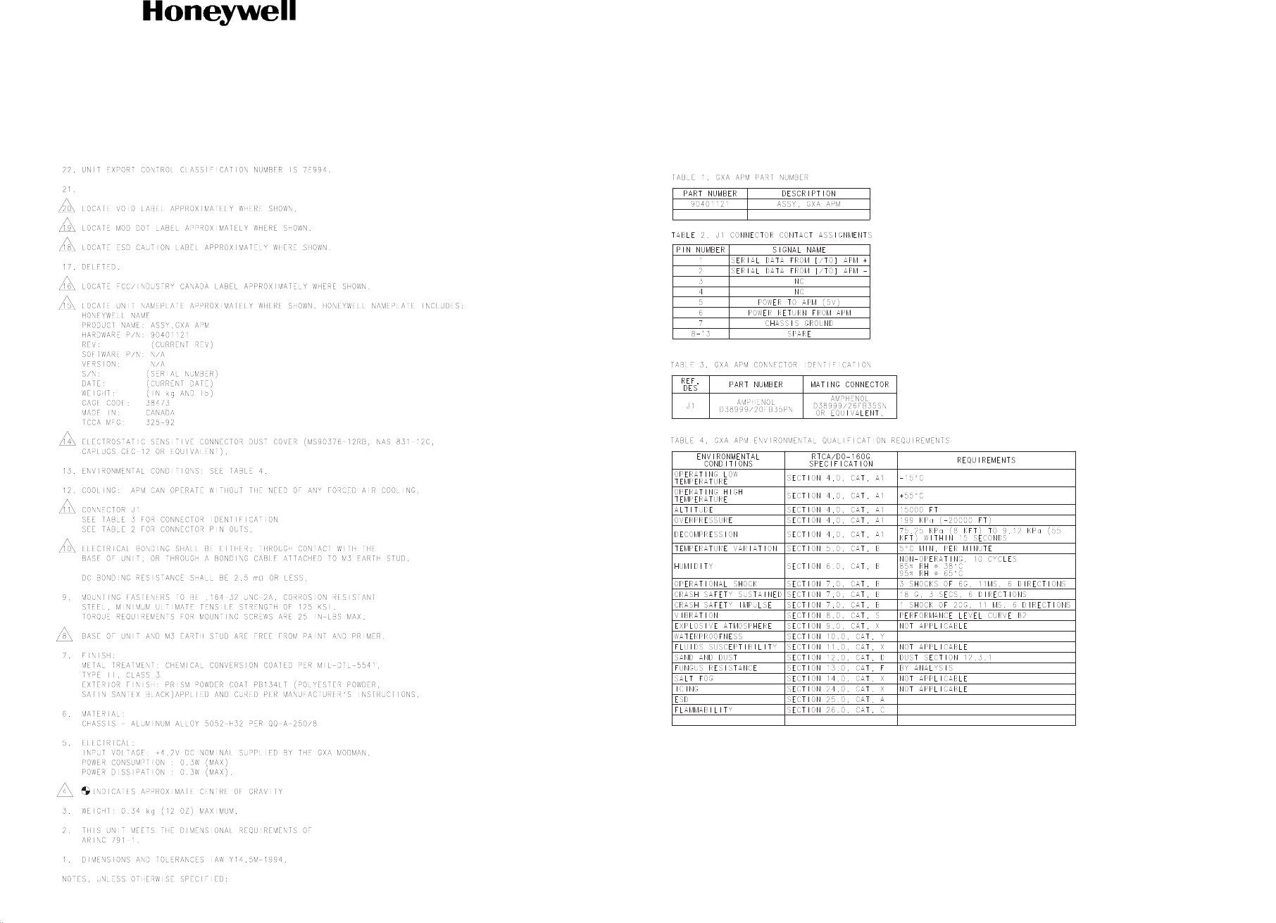
SYSTEM DESCRIPTION AND INSTALLATION MANUAL
JetWave™ System
Page 2-49
16 Sep 2015
© Honeywell International Inc. Do not copy without express permission of Honeywell.
23-15-29
Figure 2-25. APM Outline and Installation Drawing (Sheet 1 of 2)
DELETED
E90401592-1-D

SYSTEM DESCRIPTION AND INSTALLATION MANUAL
JetWave™ System
Page 2-50
16 Sep 2015
© Honeywell International Inc. Do not copy without express permission of Honeywell.
23-15-29
Blank Page
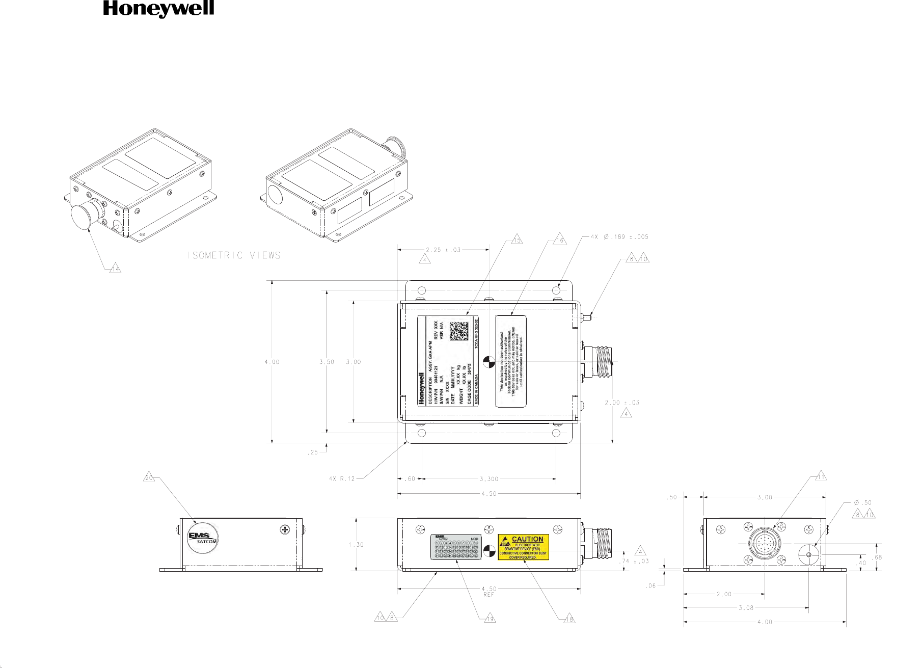
SYSTEM DESCRIPTION AND INSTALLATION MANUAL
JetWave™ System
Page 2-51
16 Sep 2015
© Honeywell International Inc. Do not copy without express permission of Honeywell.
23-15-29
Figure 2-25. APM Outline and Installation Drawing (Sheet 2 of 2)
E90401592-2-D

SYSTEM DESCRIPTION AND INSTALLATION MANUAL
JetWave™ System
Page 2-52
16 Sep 2015
© Honeywell International Inc. Do not copy without express permission of Honeywell.
23-15-29
Blank Page
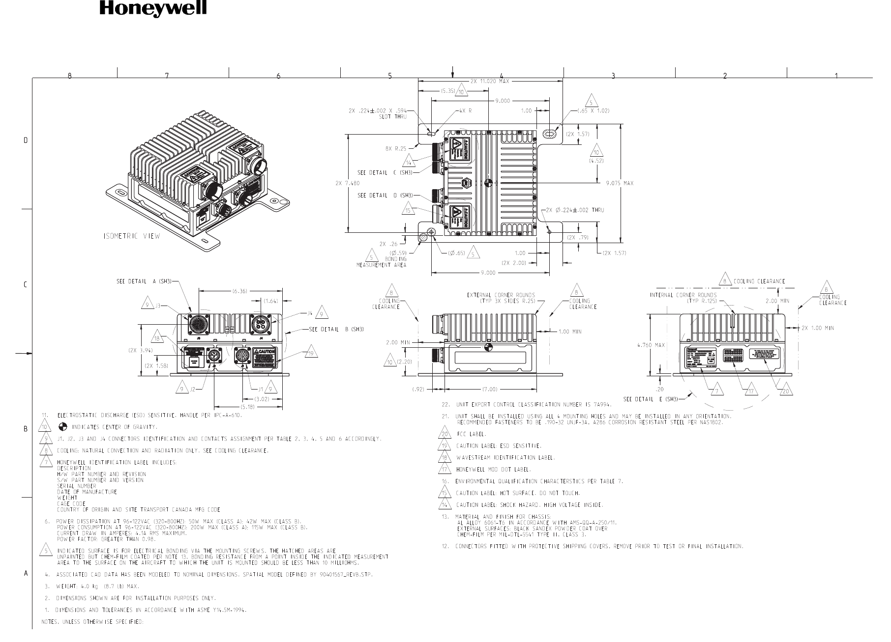
SYSTEM DESCRIPTION AND INSTALLATION MANUAL
JetWave™ System
Page 2-53
16 Sep 2015
© Honeywell International Inc. Do not copy without express permission of Honeywell.
23-15-29
Figure 2-26. KANDU Outline and Installation Drawing (Sheet 1 of 3)
E90401567-1-B

SYSTEM DESCRIPTION AND INSTALLATION MANUAL
JetWave™ System
Page 2-54
16 Sep 2015
© Honeywell International Inc. Do not copy without express permission of Honeywell.
23-15-29
Blank Page
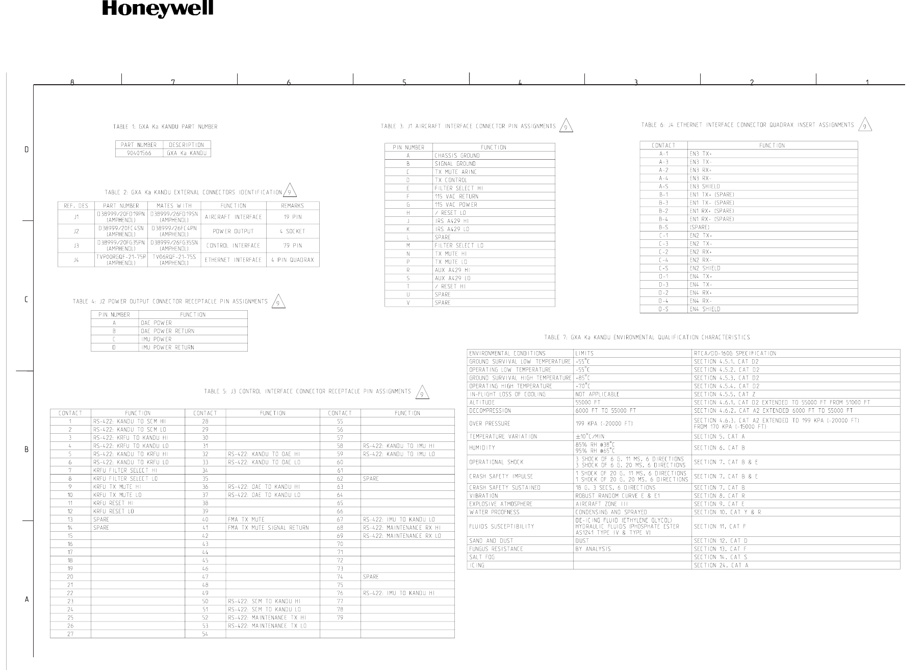
SYSTEM DESCRIPTION AND INSTALLATION MANUAL
JetWave™ System
Page 2-55
16 Sep 2015
© Honeywell International Inc. Do not copy without express permission of Honeywell.
23-15-29
Figure 2-26. KANDU Outline and Installation Drawing (Sheet 2 of 3)
E90401567-2-B

SYSTEM DESCRIPTION AND INSTALLATION MANUAL
JetWave™ System
Page 2-56
16 Sep 2015
© Honeywell International Inc. Do not copy without express permission of Honeywell.
23-15-29
Blank Page
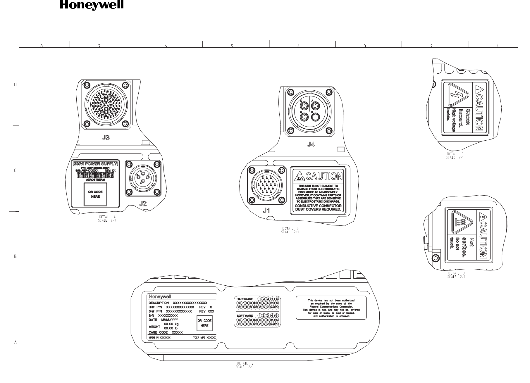
SYSTEM DESCRIPTION AND INSTALLATION MANUAL
JetWave™ System
Page 2-57
16 Sep 2015
© Honeywell International Inc. Do not copy without express permission of Honeywell.
23-15-29
Figure 2-26. KANDU Outline and Installation Drawing (Sheet 3 of 3)
E90401567-3-B

SYSTEM DESCRIPTION AND INSTALLATION MANUAL
JetWave™ System
Page 2-58
16 Sep 2015
© Honeywell International Inc. Do not copy without express permission of Honeywell.
23-15-29
Blank Page
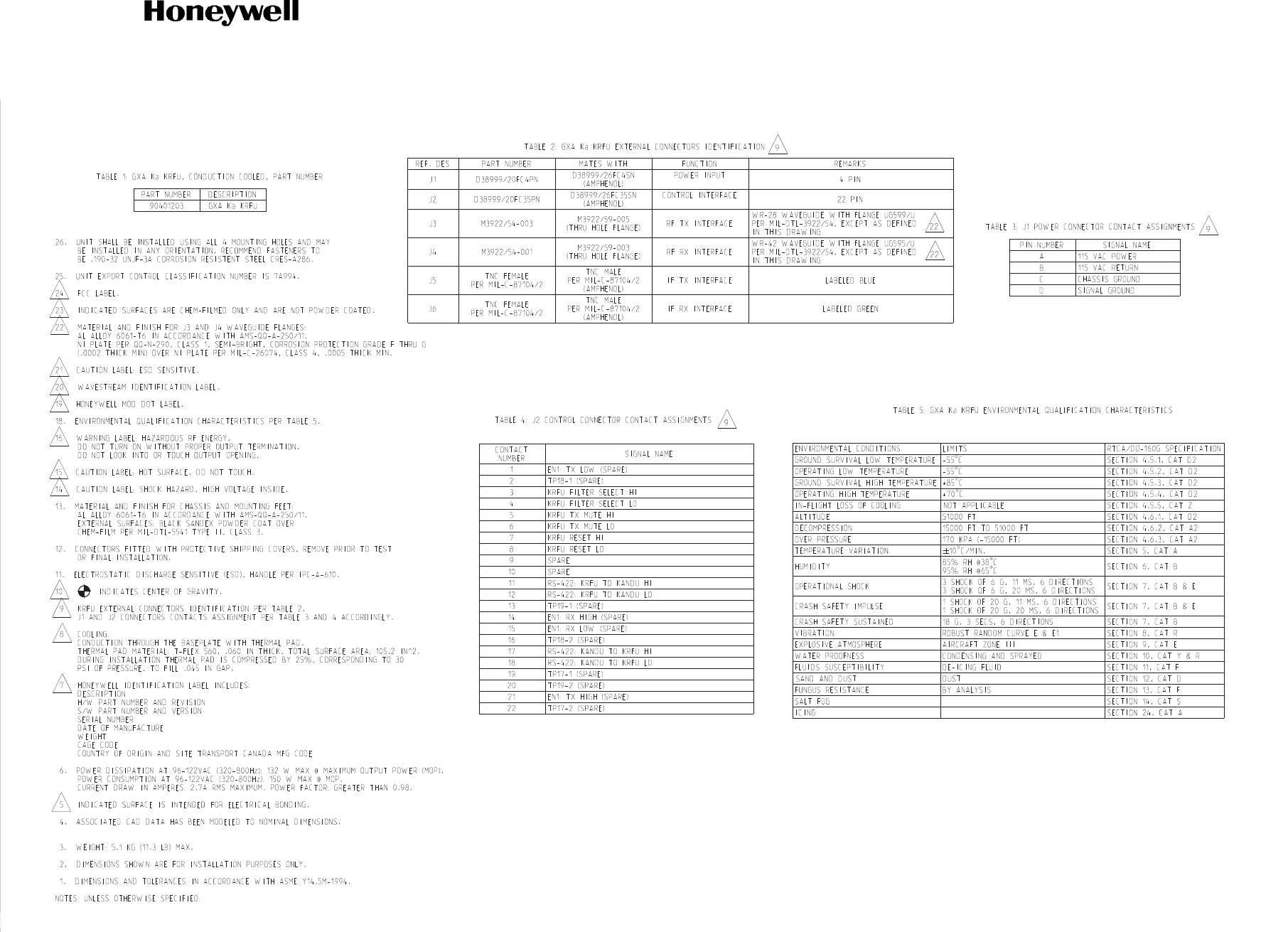
SYSTEM DESCRIPTION AND INSTALLATION MANUAL
JetWave™ System
Page 2-59
16 Sep 2015
© Honeywell International Inc. Do not copy without express permission of Honeywell.
23-15-29
Figure 2-27. KRFU, Conduction-Cooled 1, Outline and Installation Drawing (Sheet 1 of 3)
PRODUCTION - Release - 15 Aug 2014 13:44:15 MST - Printed on 26 Aug 2014
E90401573-1-
A

SYSTEM DESCRIPTION AND INSTALLATION MANUAL
JetWave™ System
Page 2-60
16 Sep 2015
© Honeywell International Inc. Do not copy without express permission of Honeywell.
23-15-29
Blank Page
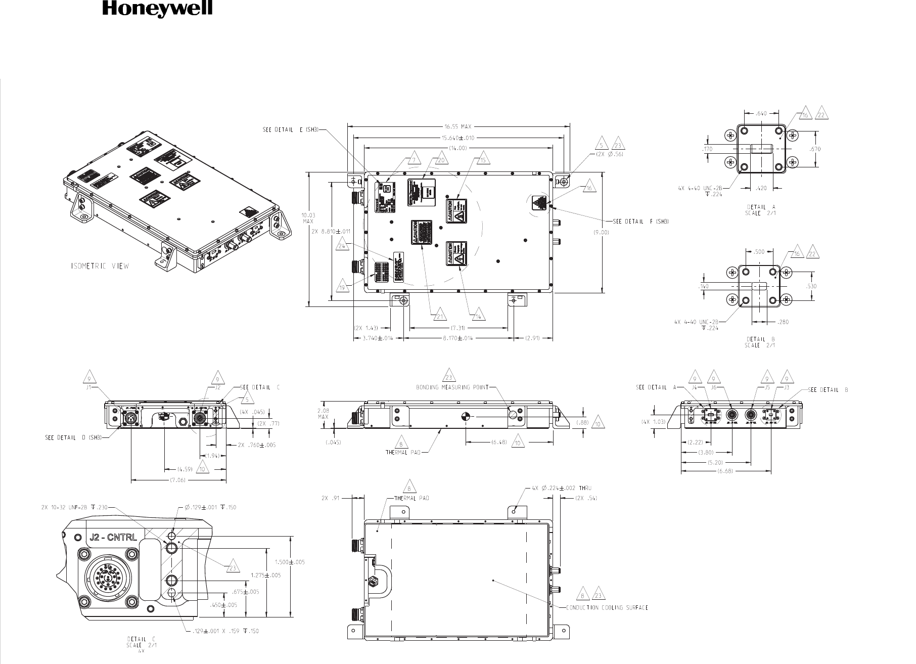
SYSTEM DESCRIPTION AND INSTALLATION MANUAL
JetWave™ System
Page 2-61
16 Sep 2015
© Honeywell International Inc. Do not copy without express permission of Honeywell.
23-15-29
Figure 2-27. KRFU, Conduction-Cooled 1, Outline and Installation Drawing (Sheet 2 of 3)
E90401573-2-
A

SYSTEM DESCRIPTION AND INSTALLATION MANUAL
JetWave™ System
Page 2-62
16 Sep 2015
© Honeywell International Inc. Do not copy without express permission of Honeywell.
23-15-29
Blank Page
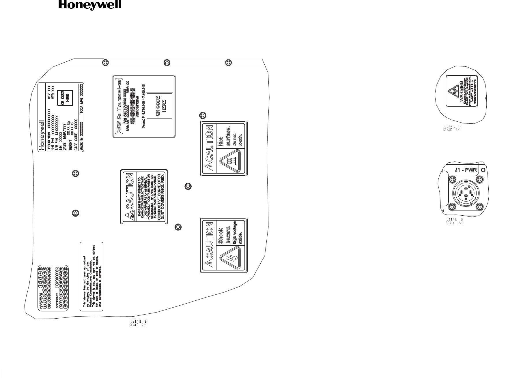
SYSTEM DESCRIPTION AND INSTALLATION MANUAL
JetWave™ System
Page 2-63
16 Sep 2015
© Honeywell International Inc. Do not copy without express permission of Honeywell.
23-15-29
Figure 2-27. KRFU, Conduction-Cooled 1, Outline and Installation Drawing (Sheet 3 of 3)
E90401573-3-
A

SYSTEM DESCRIPTION AND INSTALLATION MANUAL
JetWave™ System
Page 2-64
16 Sep 2015
© Honeywell International Inc. Do not copy without express permission of Honeywell.
23-15-29
Blank Page
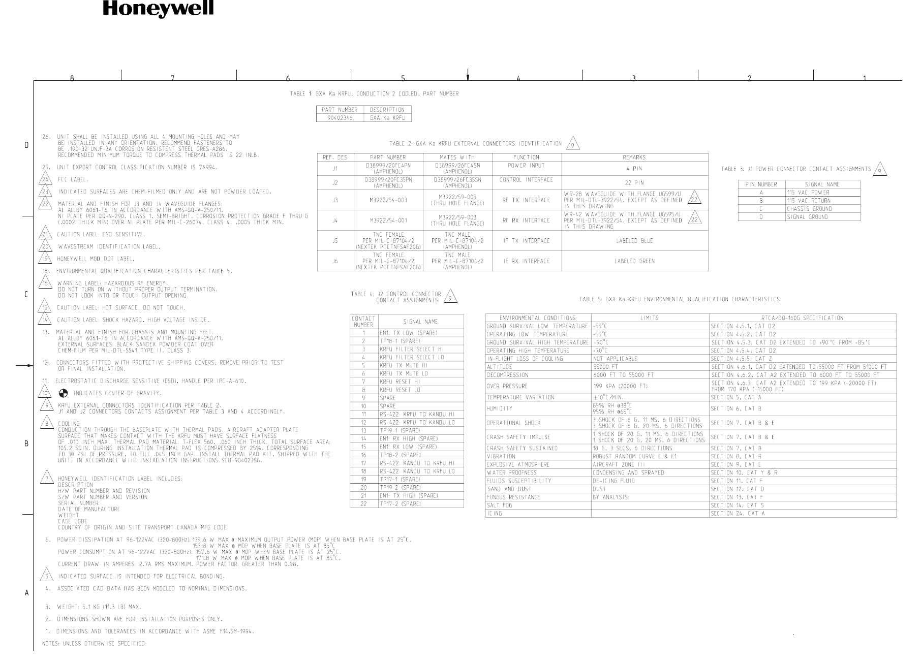
SYSTEM DESCRIPTION AND INSTALLATION MANUAL
JetWave™ System
Page 2-65
16 Sep 2015
© Honeywell International Inc. Do not copy without express permission of Honeywell.
23-15-29
Figure 2-28. KRFU, Conduction-Cooled 2, Outline and Installation Drawing (Sheet 1 of 3)
E90402347-1-B

SYSTEM DESCRIPTION AND INSTALLATION MANUAL
JetWave™ System
Page 2-66
16 Sep 2015
© Honeywell International Inc. Do not copy without express permission of Honeywell.
23-15-29
Blank Page
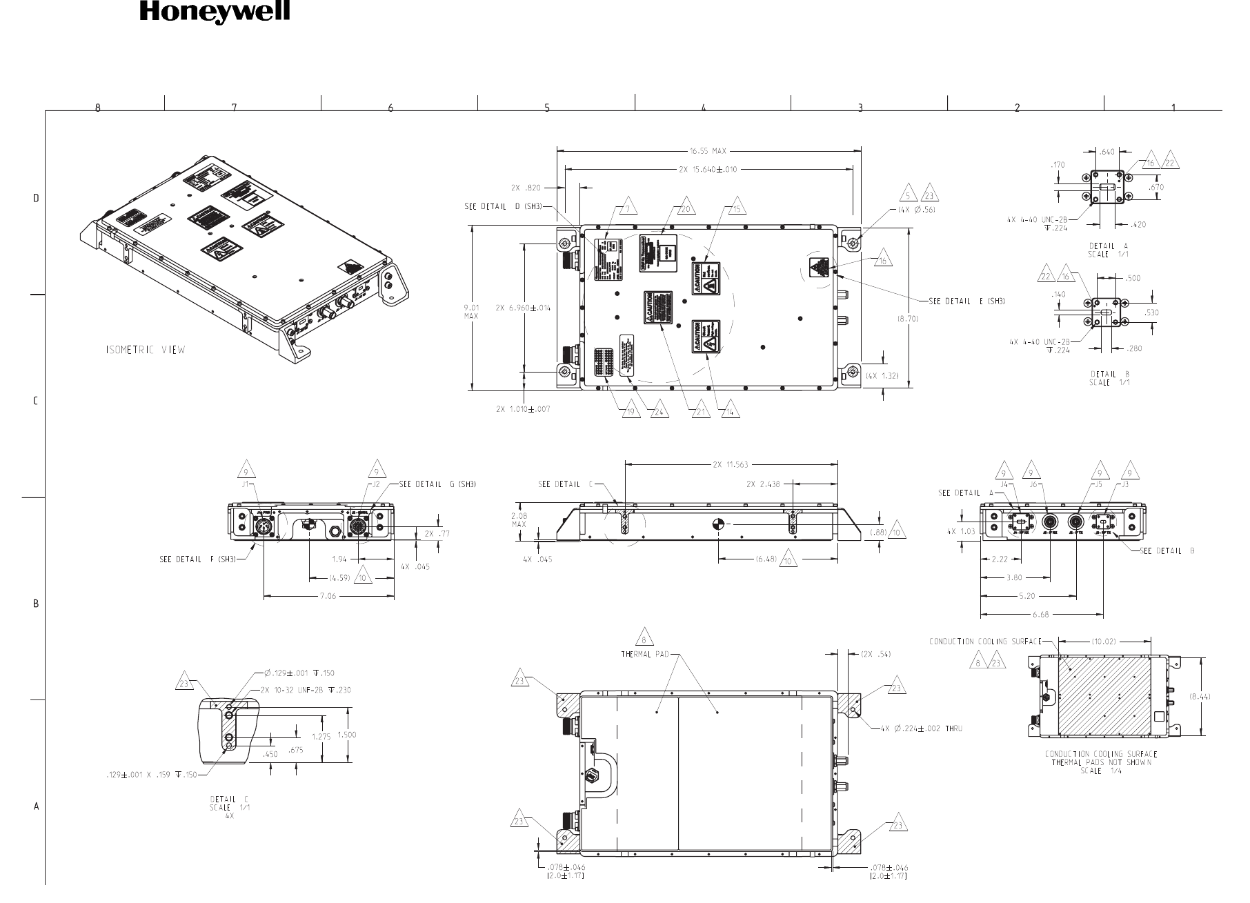
SYSTEM DESCRIPTION AND INSTALLATION MANUAL
JetWave™ System
Page 2-67
16 Sep 2015
© Honeywell International Inc. Do not copy without express permission of Honeywell.
23-15-29
Figure 2-28. KRFU, Conduction-Cooled 2, Outline and Installation Drawing (Sheet 2 of 3)
E90402347-2-B

SYSTEM DESCRIPTION AND INSTALLATION MANUAL
JetWave™ System
Page 2-68
16 Sep 2015
© Honeywell International Inc. Do not copy without express permission of Honeywell.
23-15-29
Blank Page
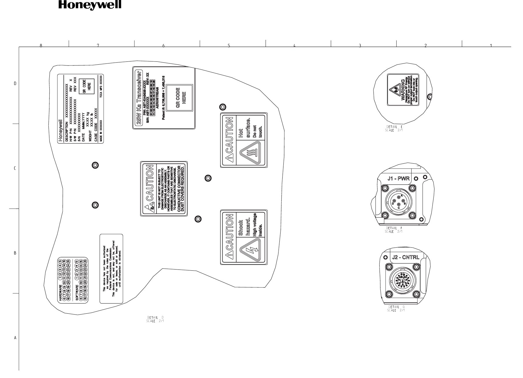
SYSTEM DESCRIPTION AND INSTALLATION MANUAL
JetWave™ System
Page 2-69
16 Sep 2015
© Honeywell International Inc. Do not copy without express permission of Honeywell.
23-15-29
Figure 2-28. KRFU, Conduction-Cooled 2, Outline and Installation Drawing (Sheet 3 of 3)
E90402347-3-B

SYSTEM DESCRIPTION AND INSTALLATION MANUAL
JetWave™ System
Page 2-70
16 Sep 2015
© Honeywell International Inc. Do not copy without express permission of Honeywell.
23-15-29
Blank Page