EMS Technologies Canada JETWAVE2 Jetwave User Manual 23 15 29R004
EMS Technologies Canada, Ltd. Jetwave 23 15 29R004
UserManual.wiki
>
EMS Technologies Canada
>
JETWAVE2 User Manual
>
User Manual_Part 6
Contents
1.
User Manual_Part 1
2.
User Manual_Part 2
3.
User Manual_Part 3
4.
User Manual_Part 4
5.
User Manual_Part 5
6.
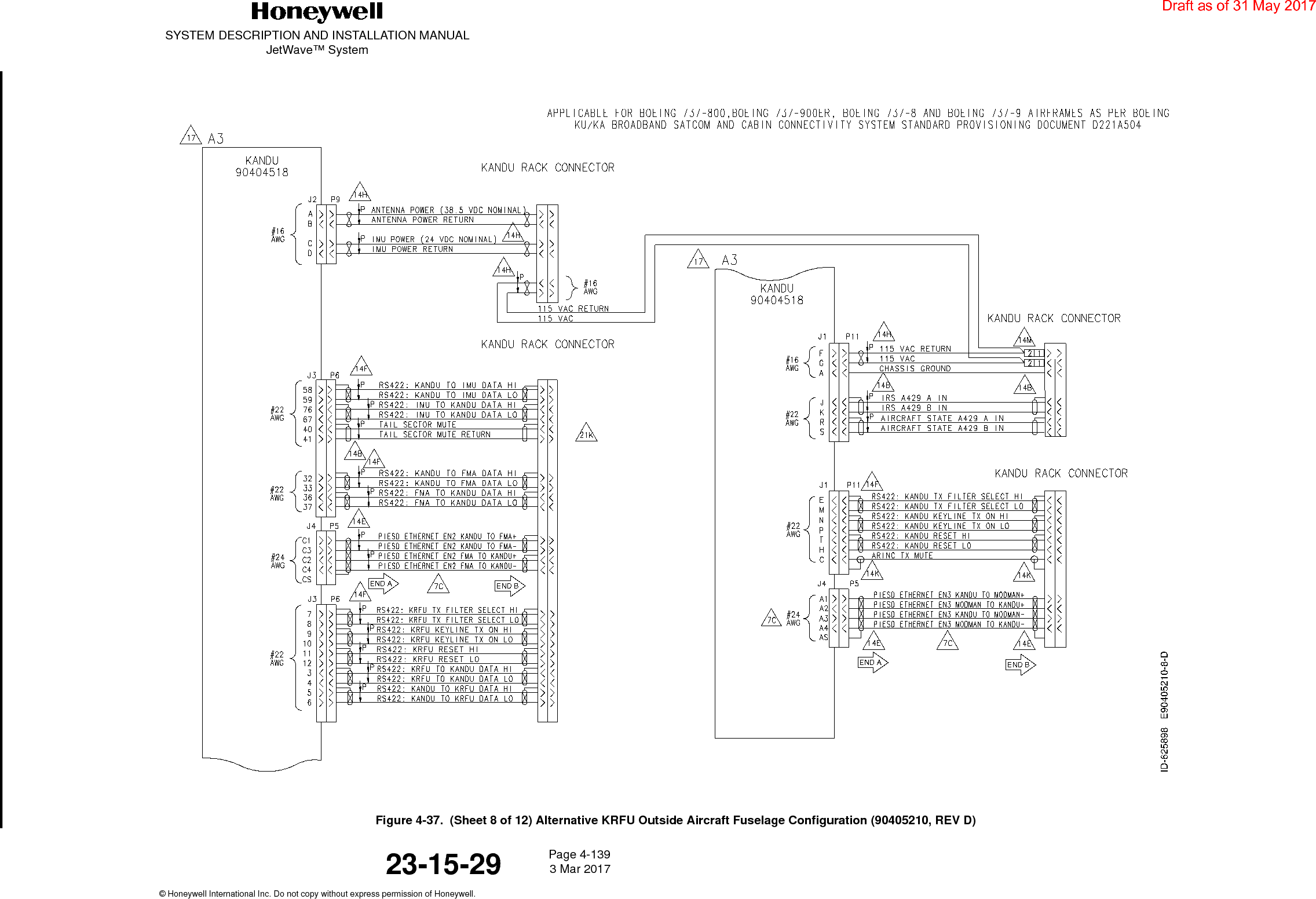
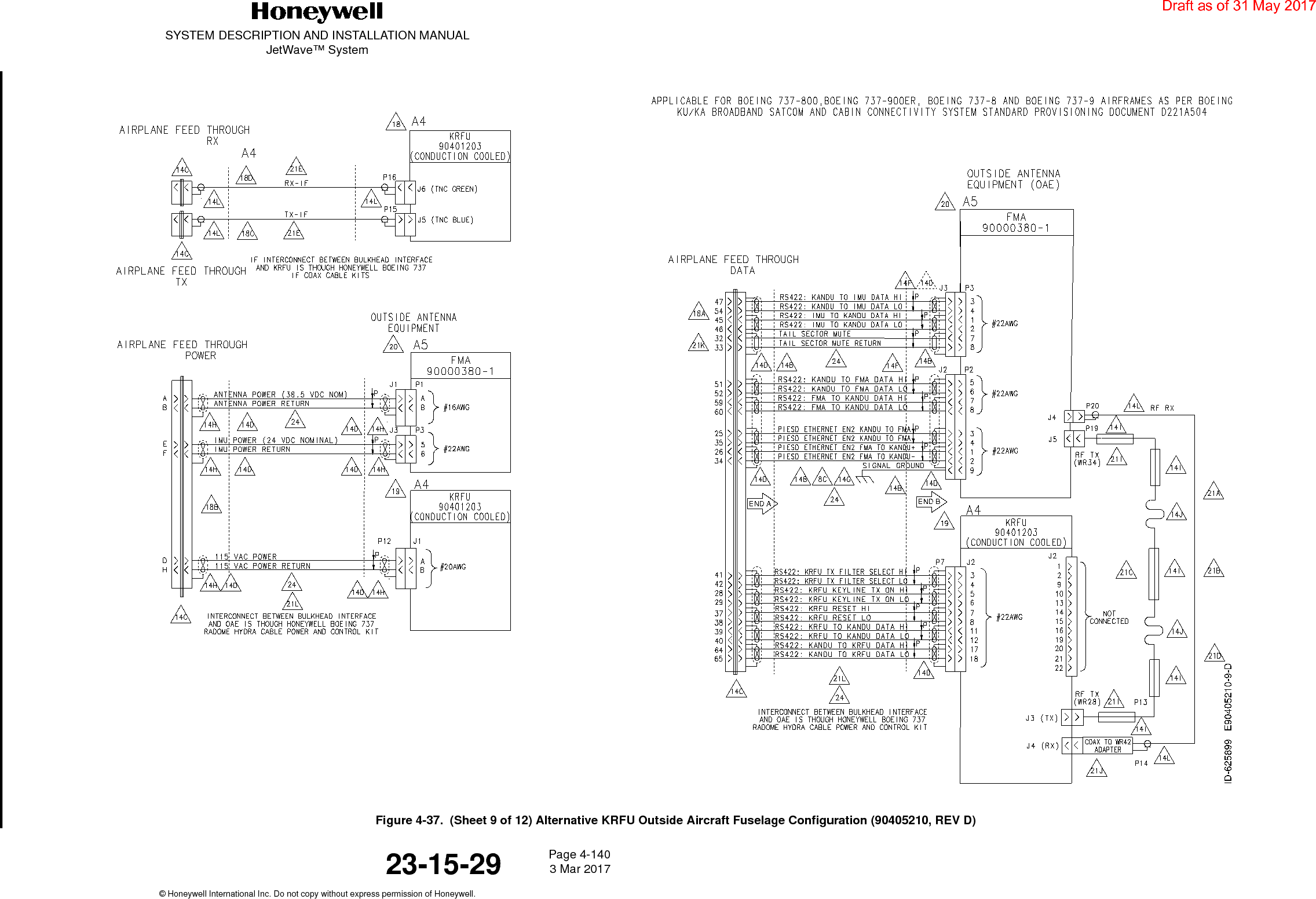
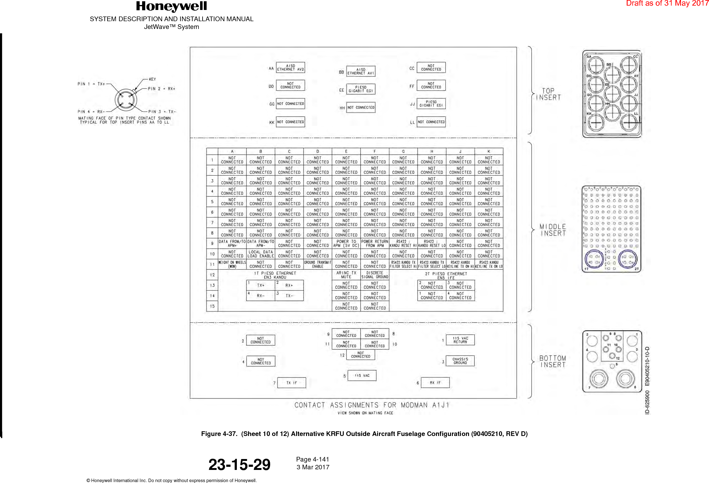
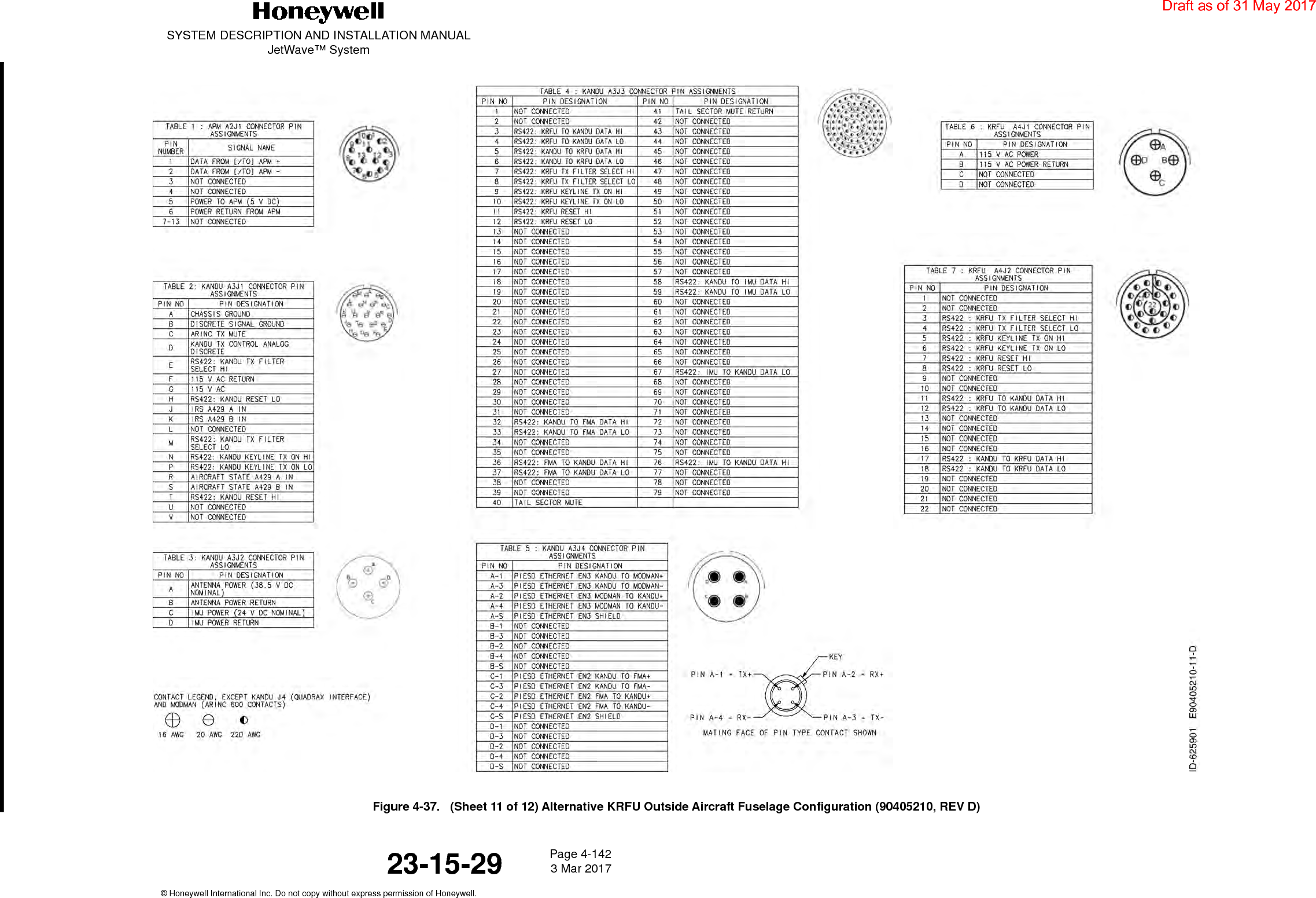
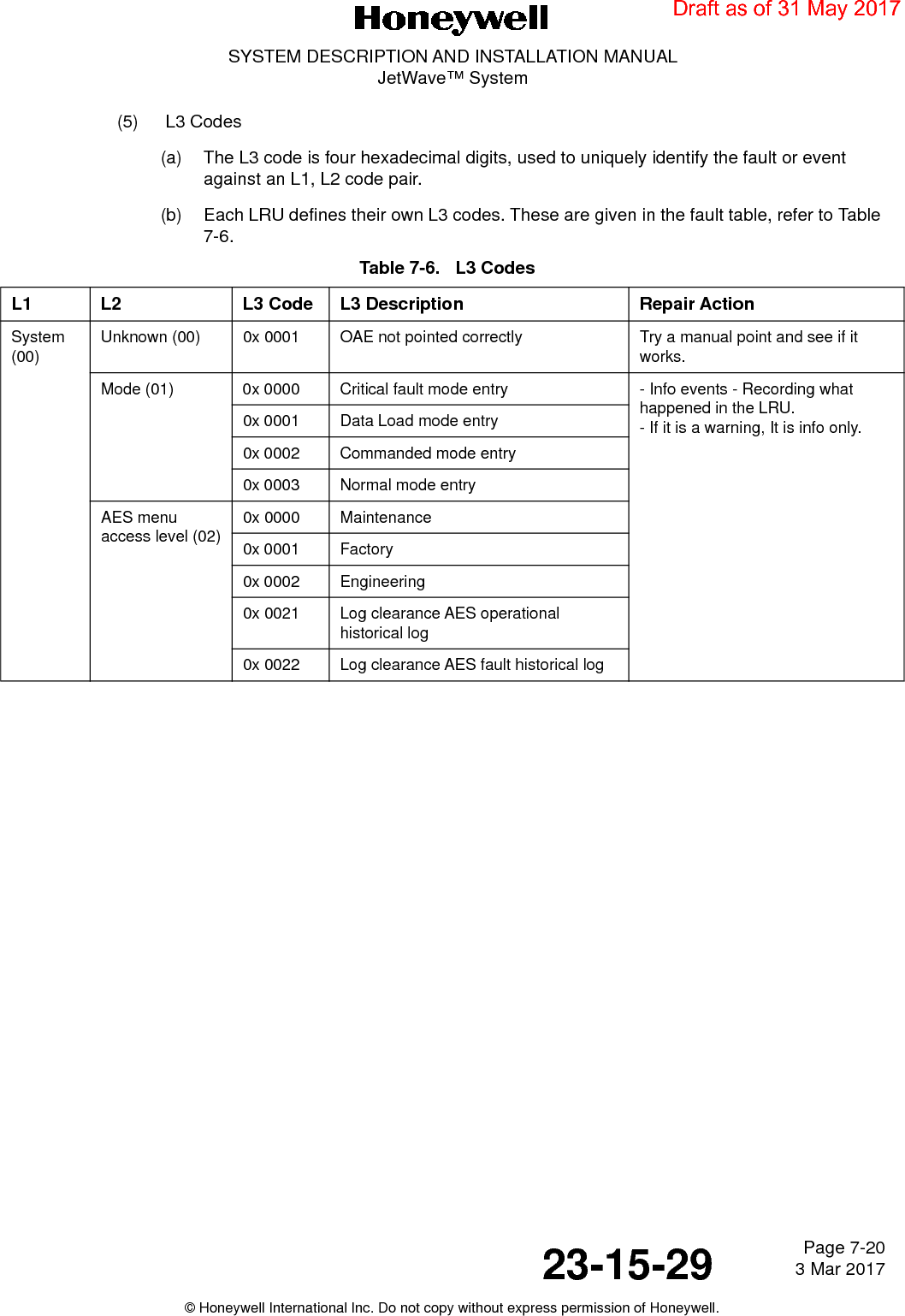
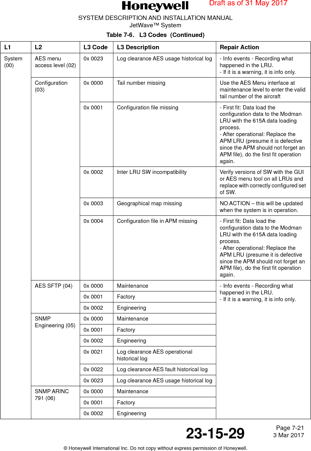
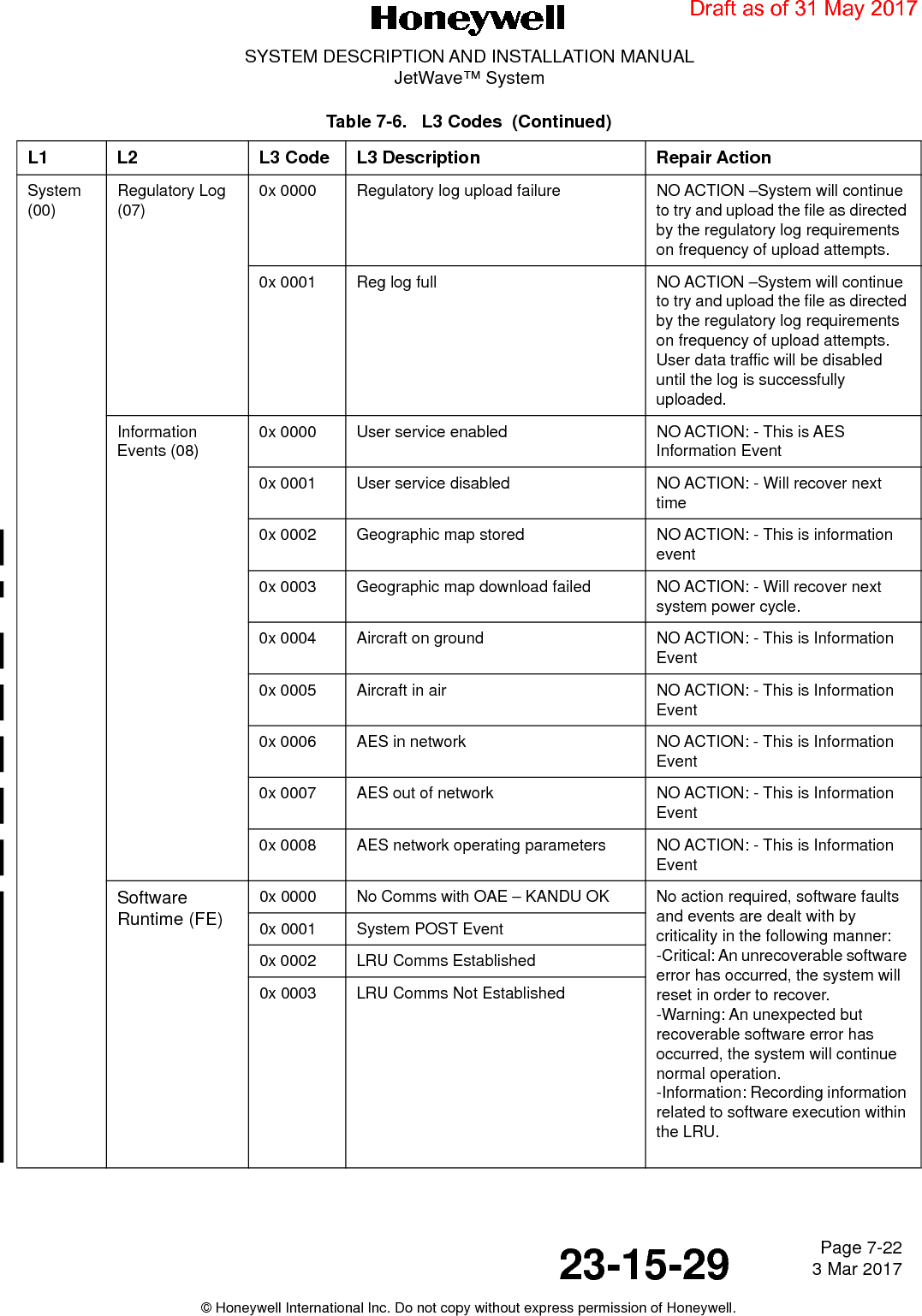
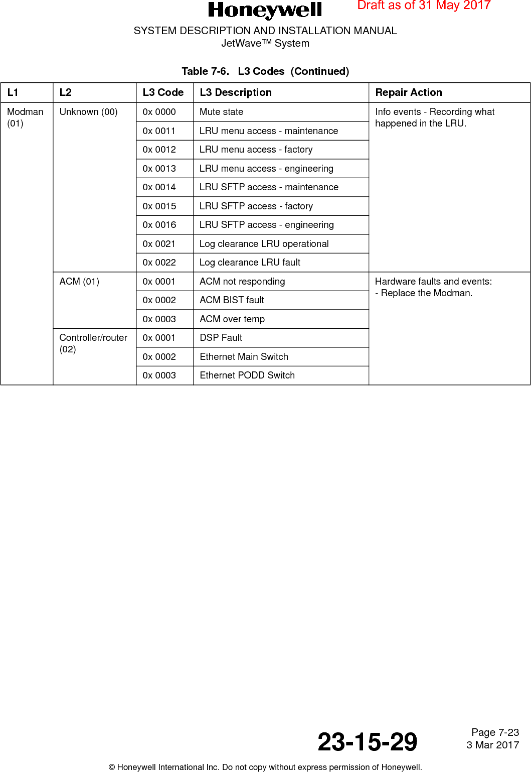
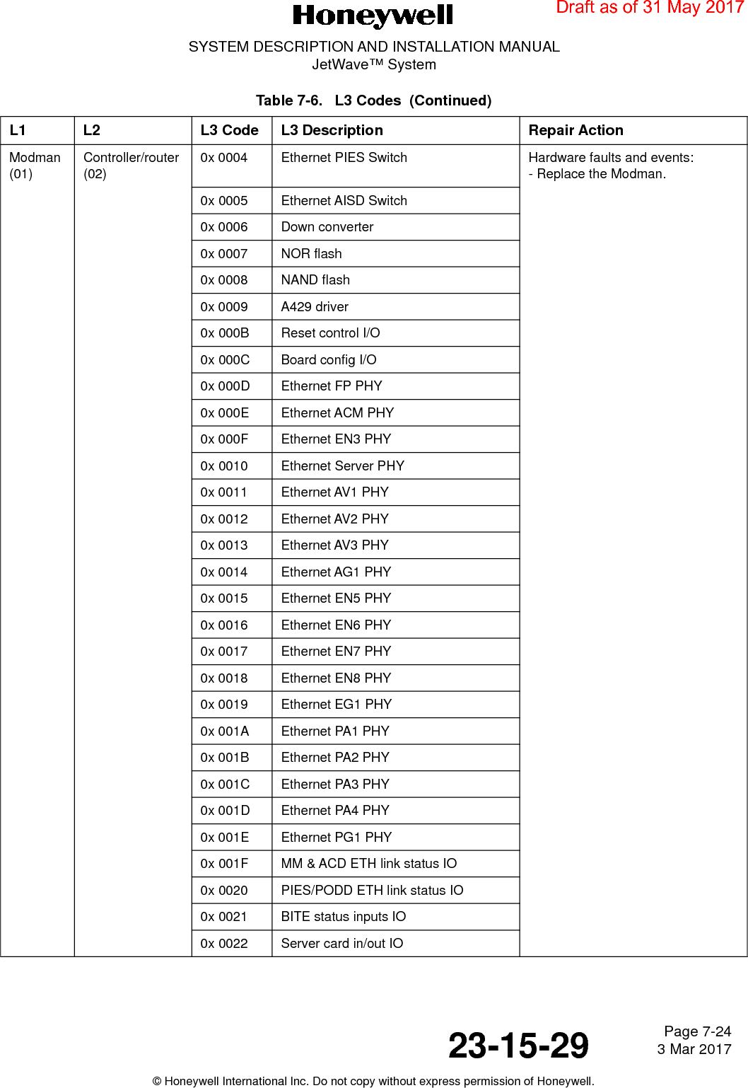
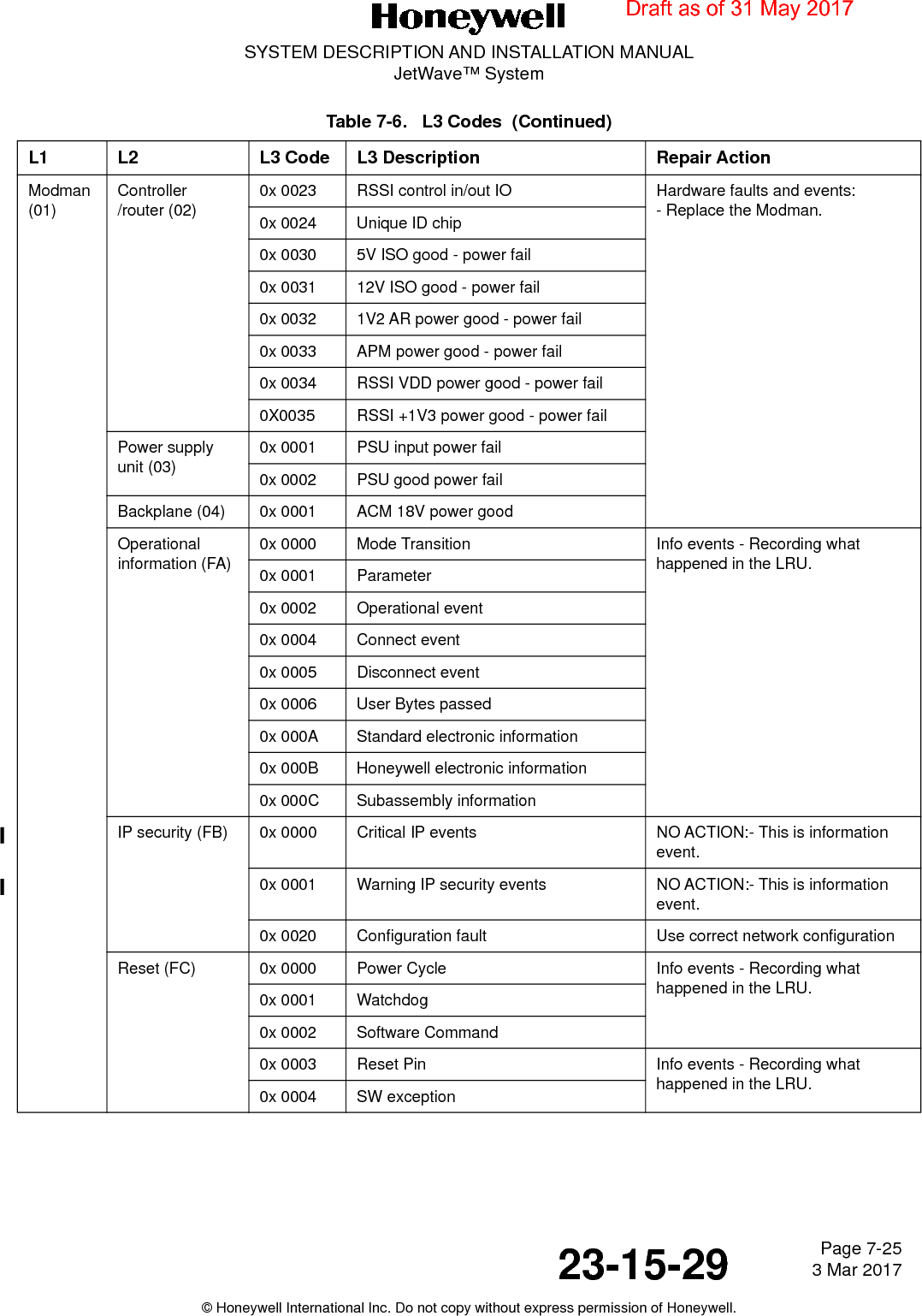
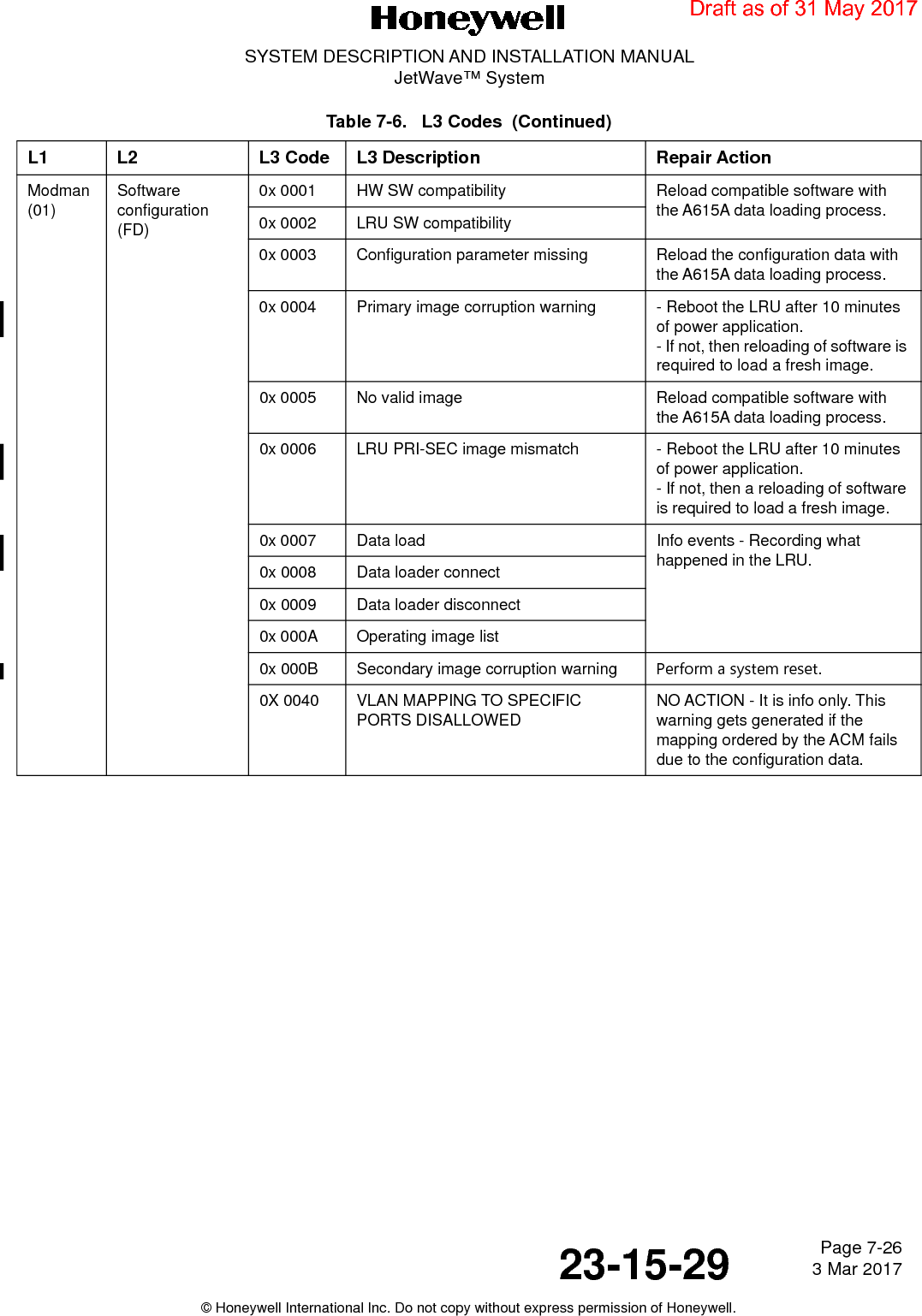
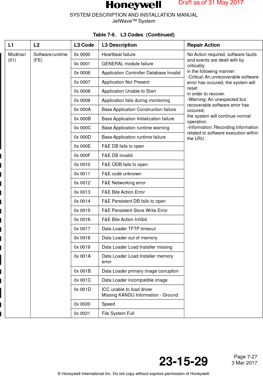
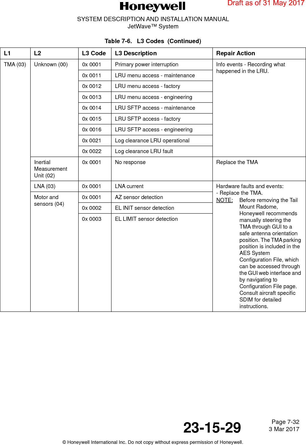
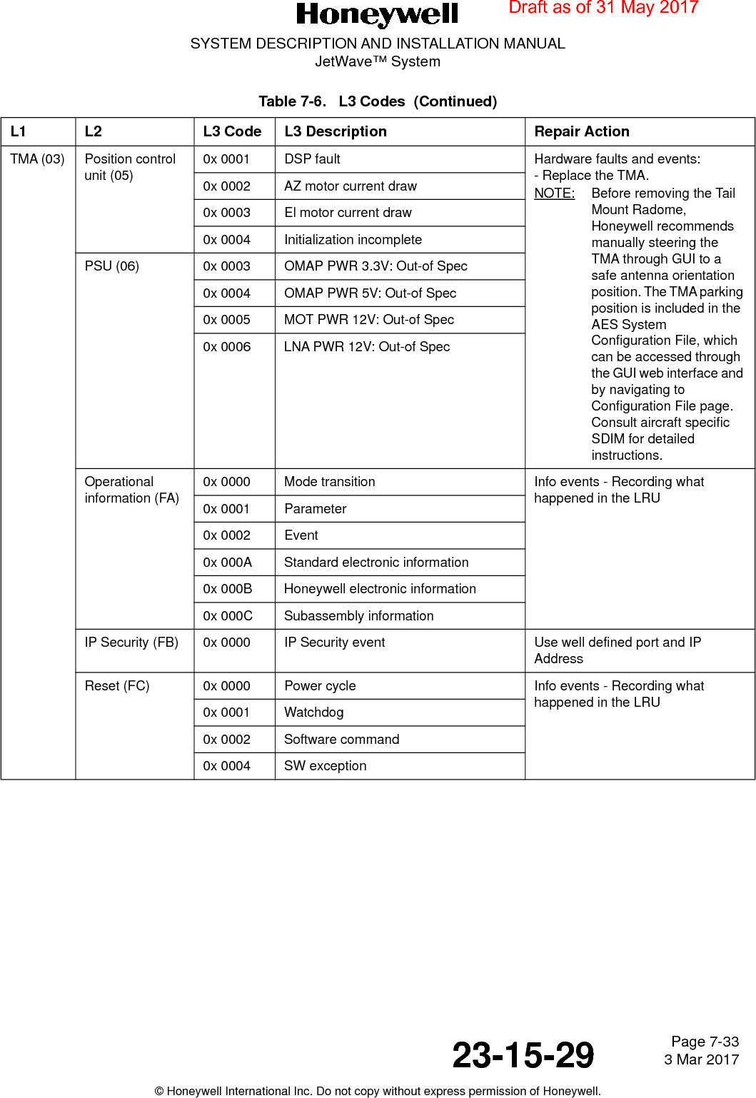
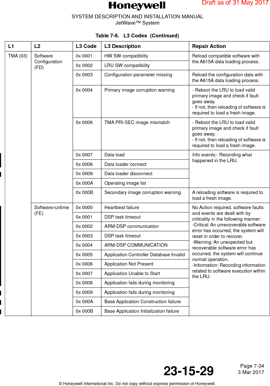
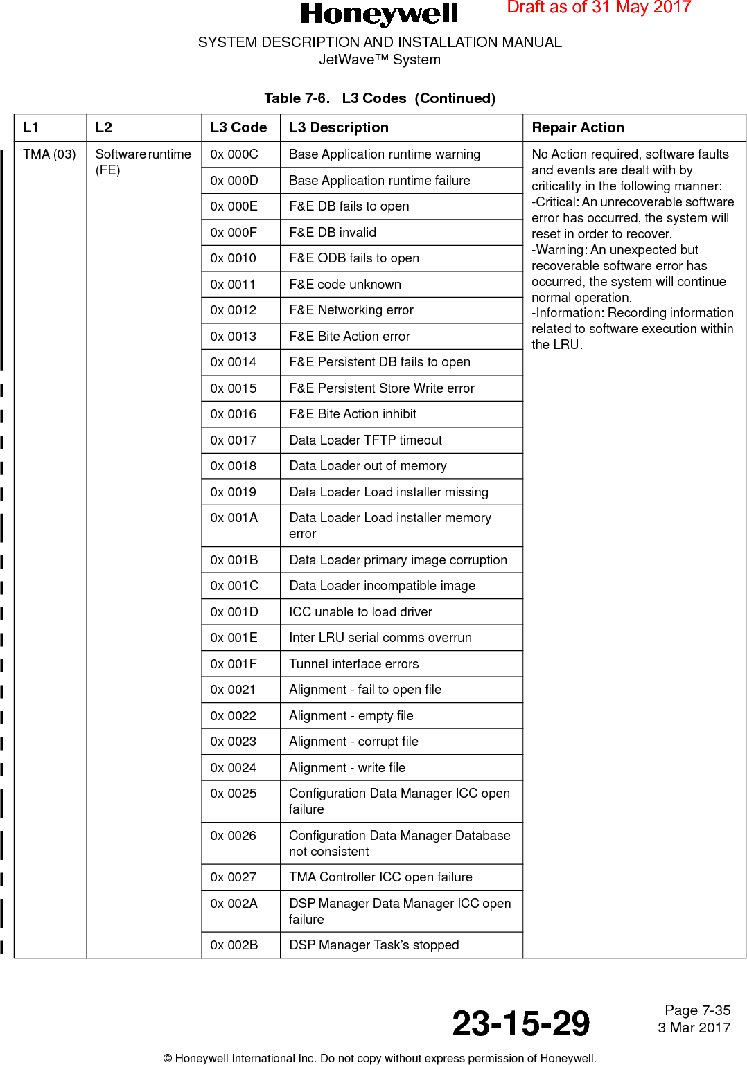
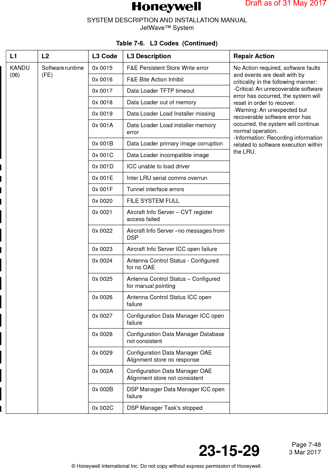
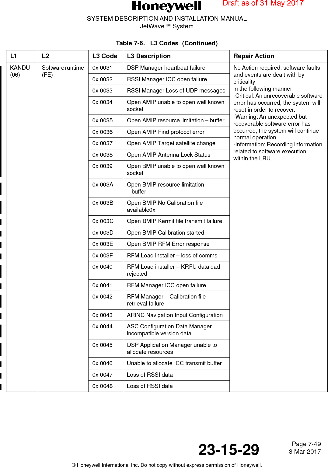
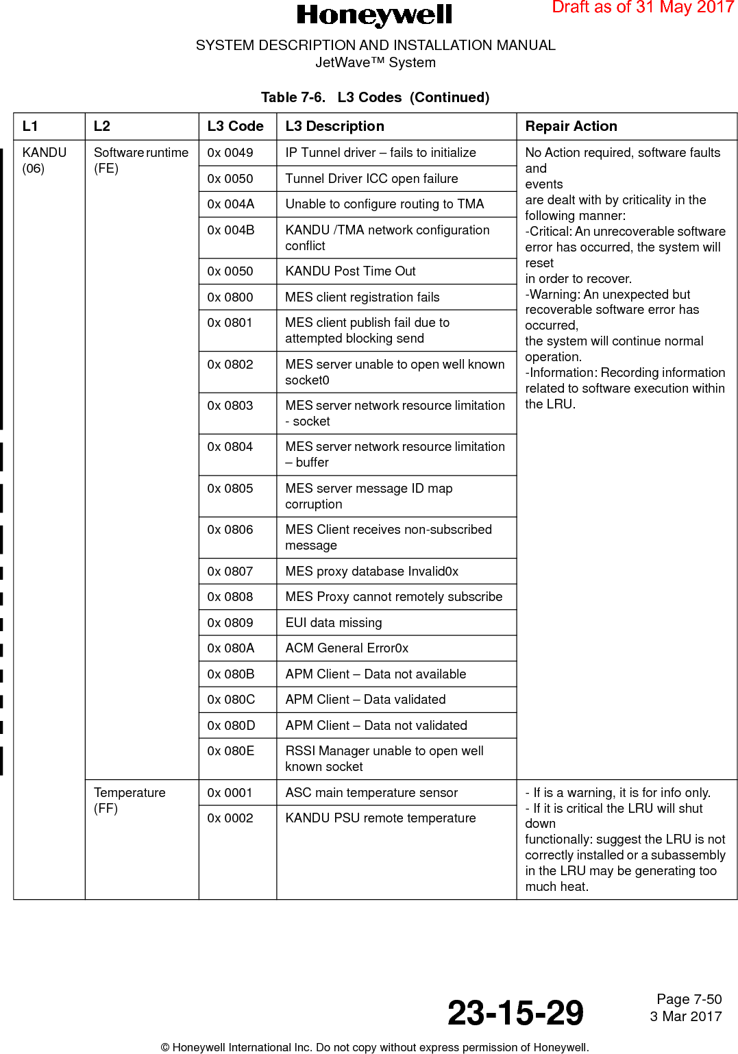
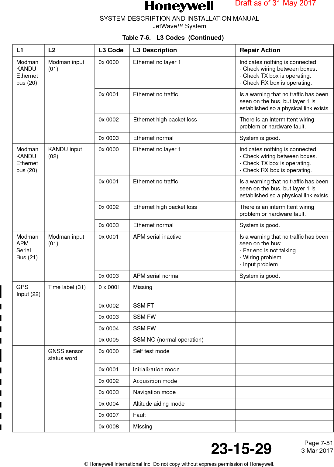
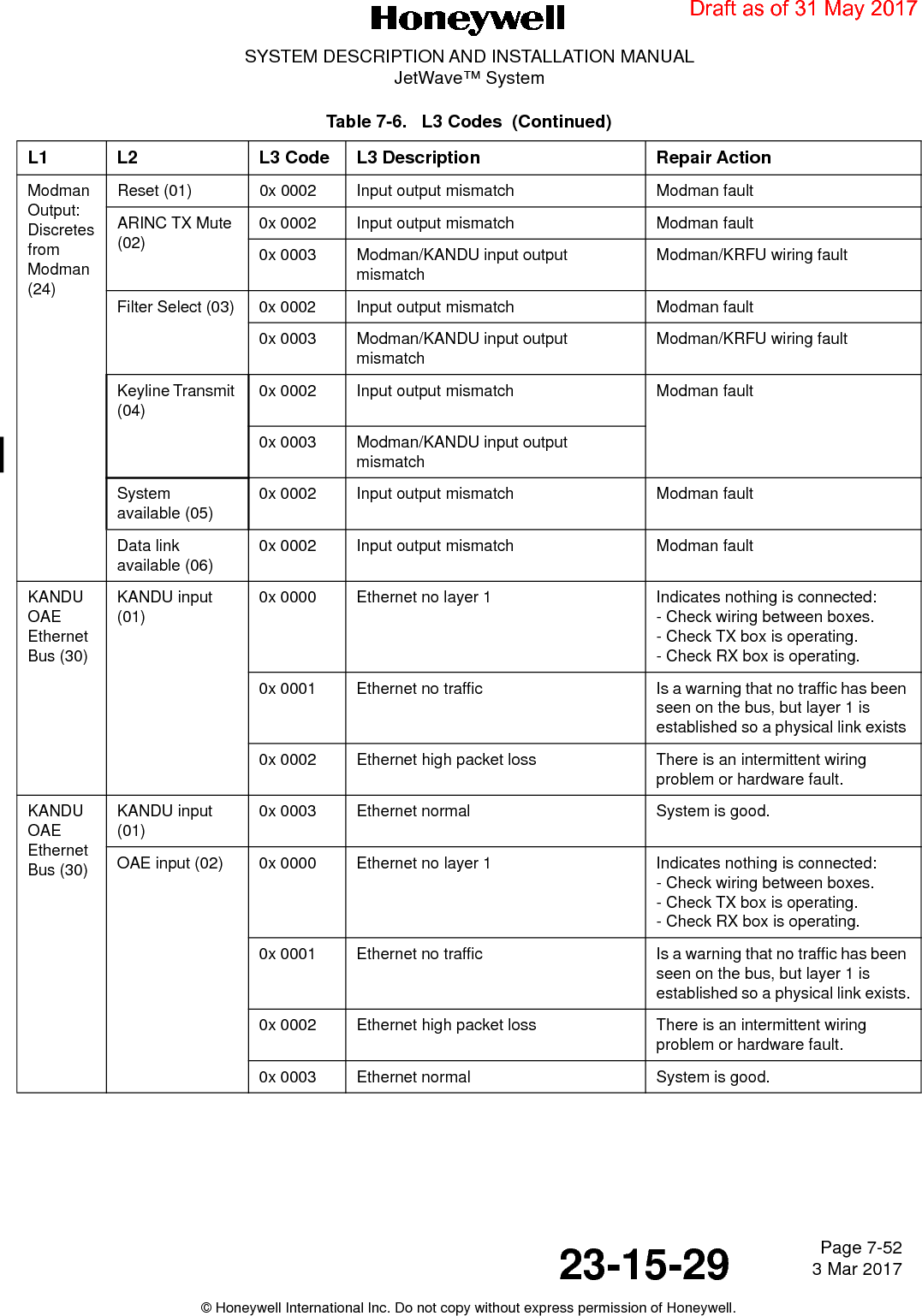
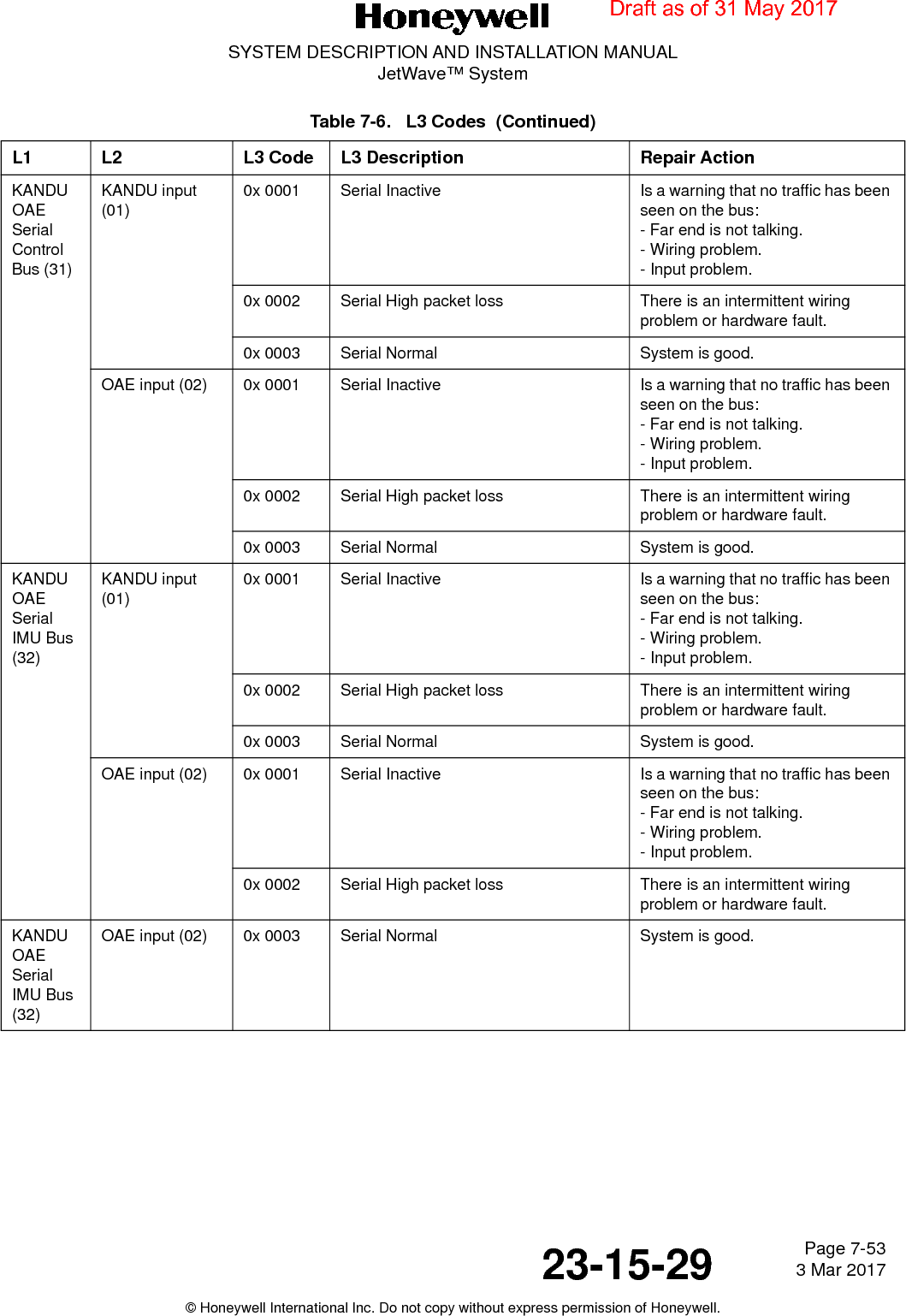
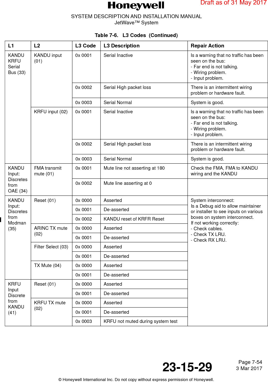
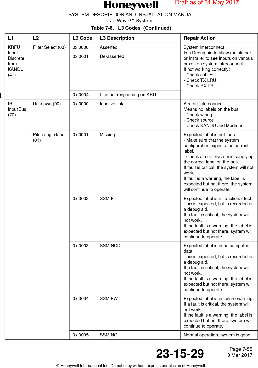
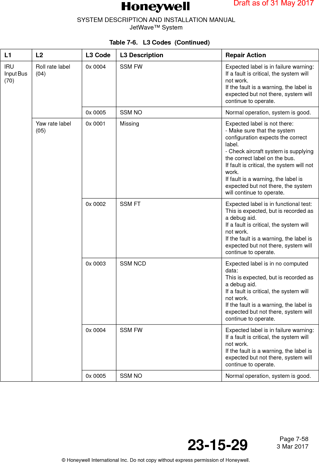
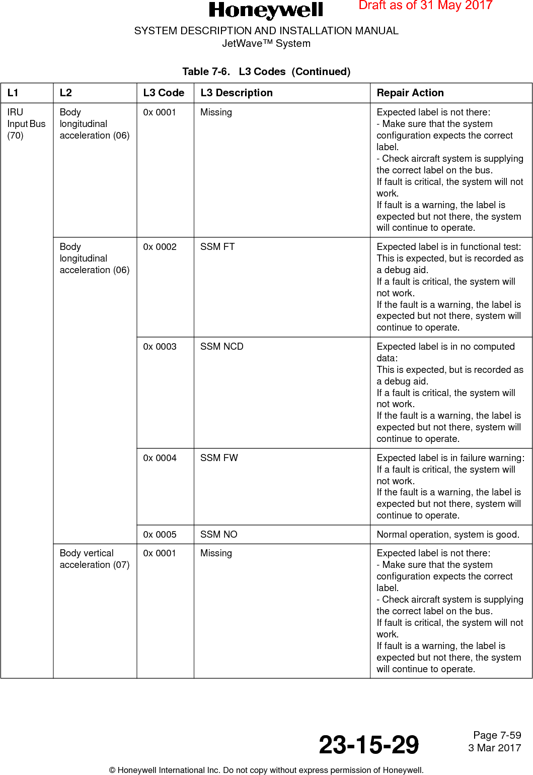
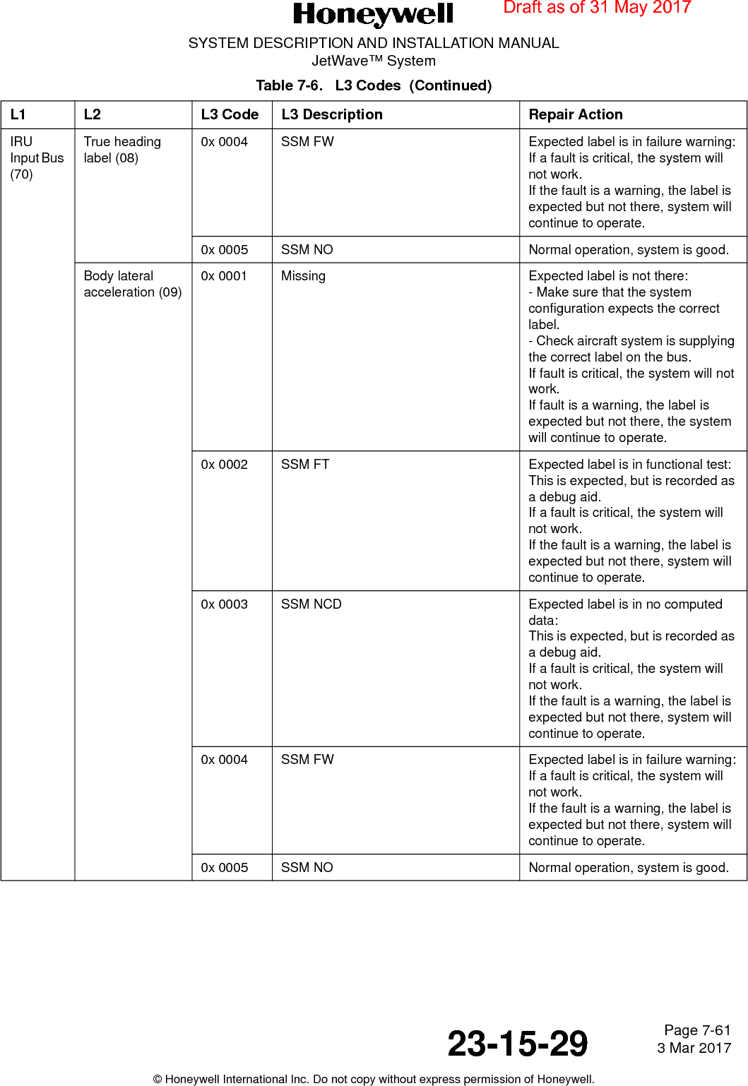
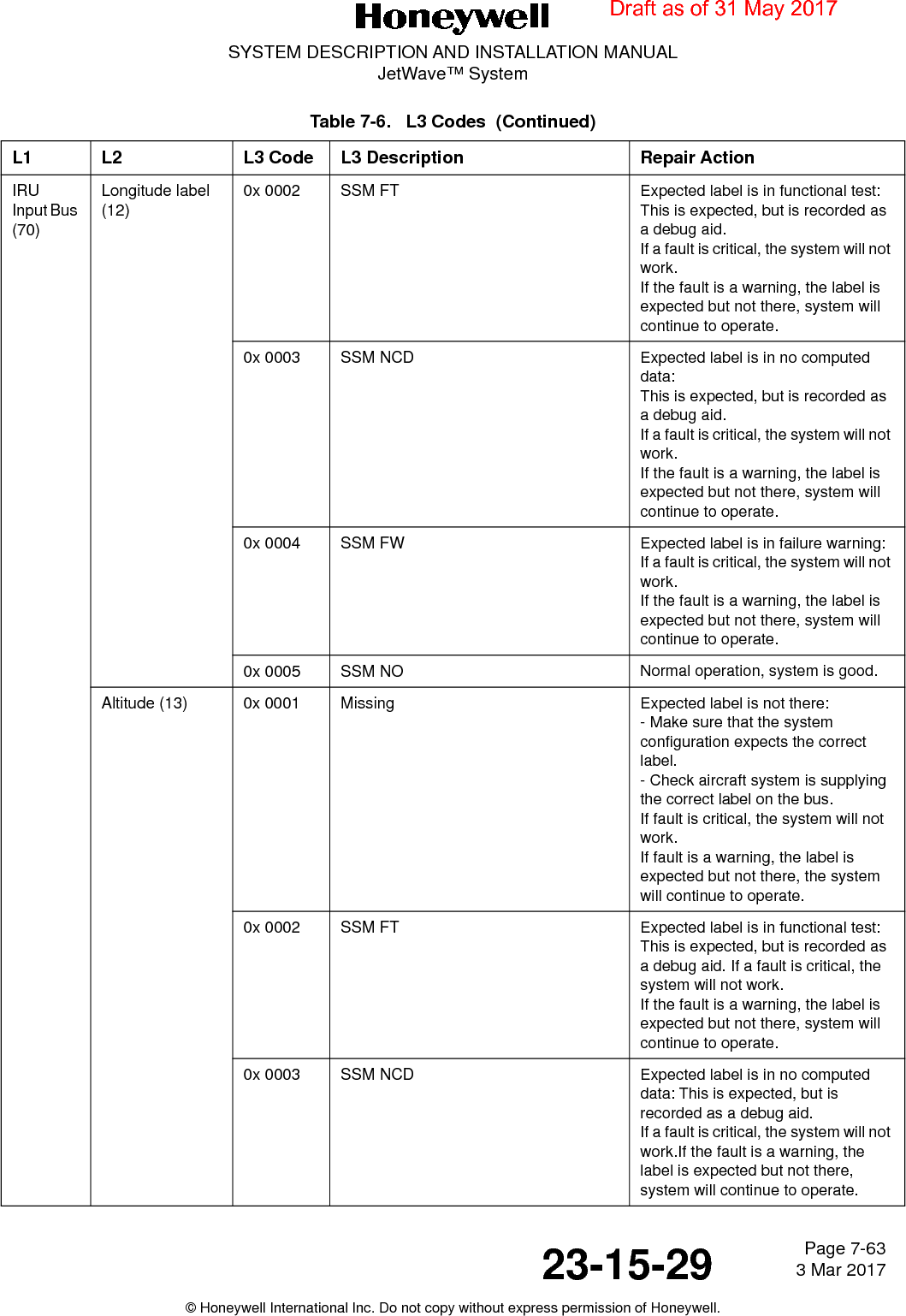
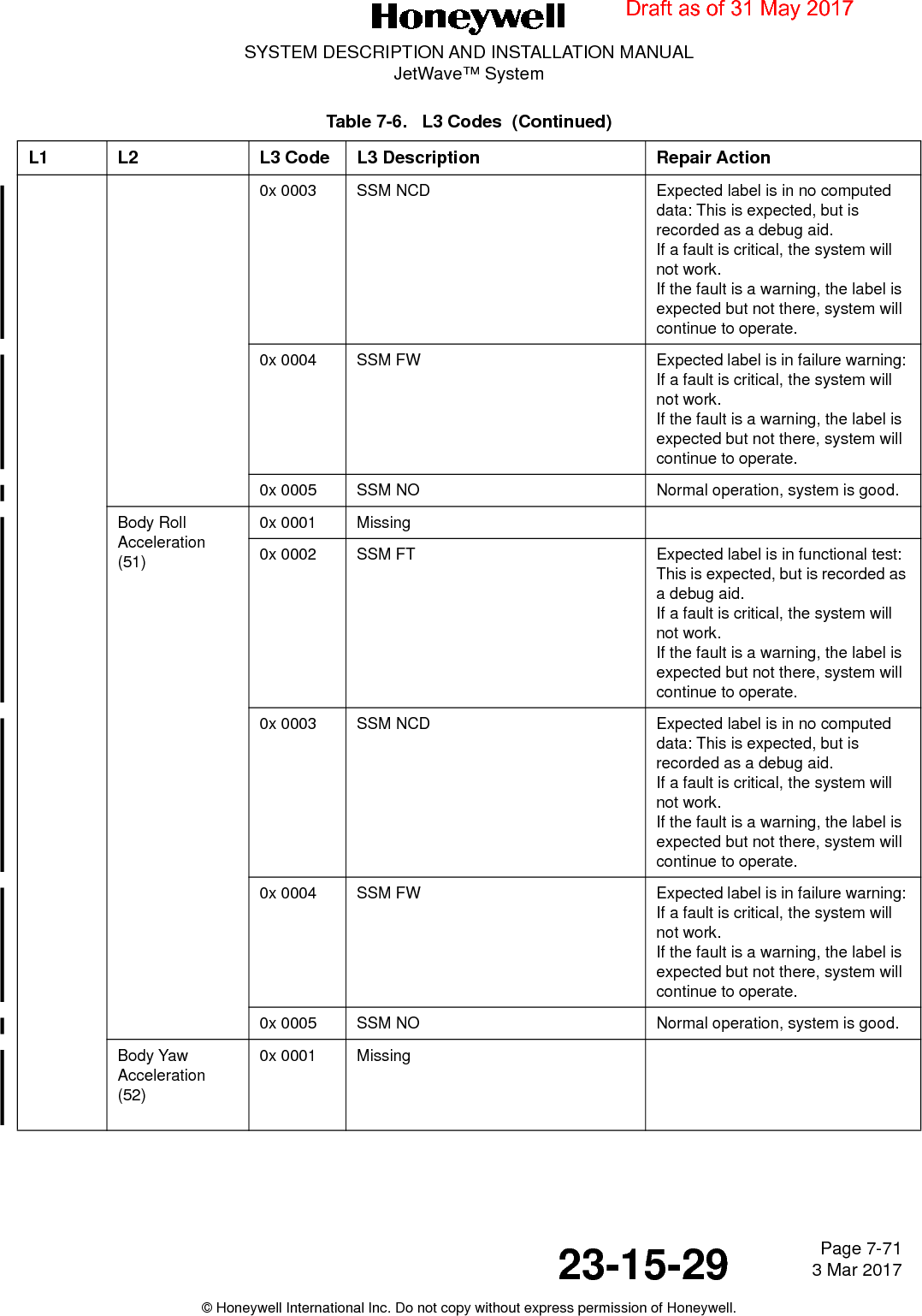
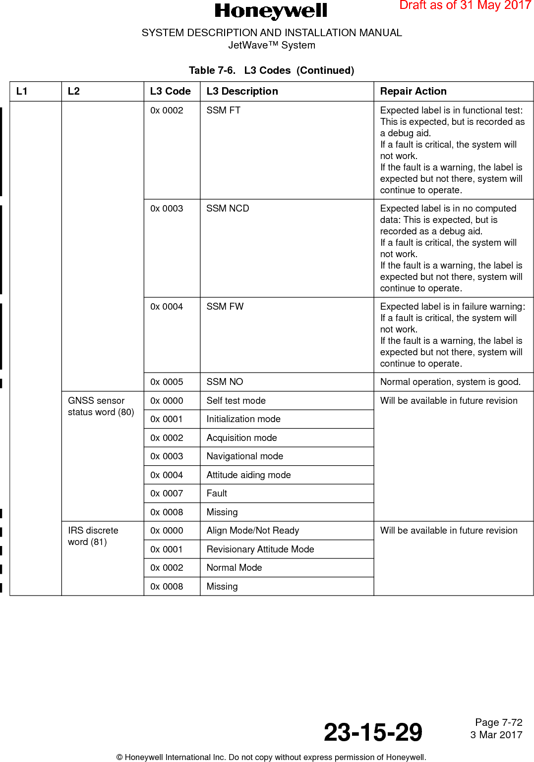
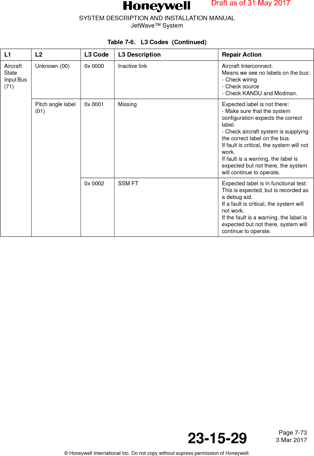
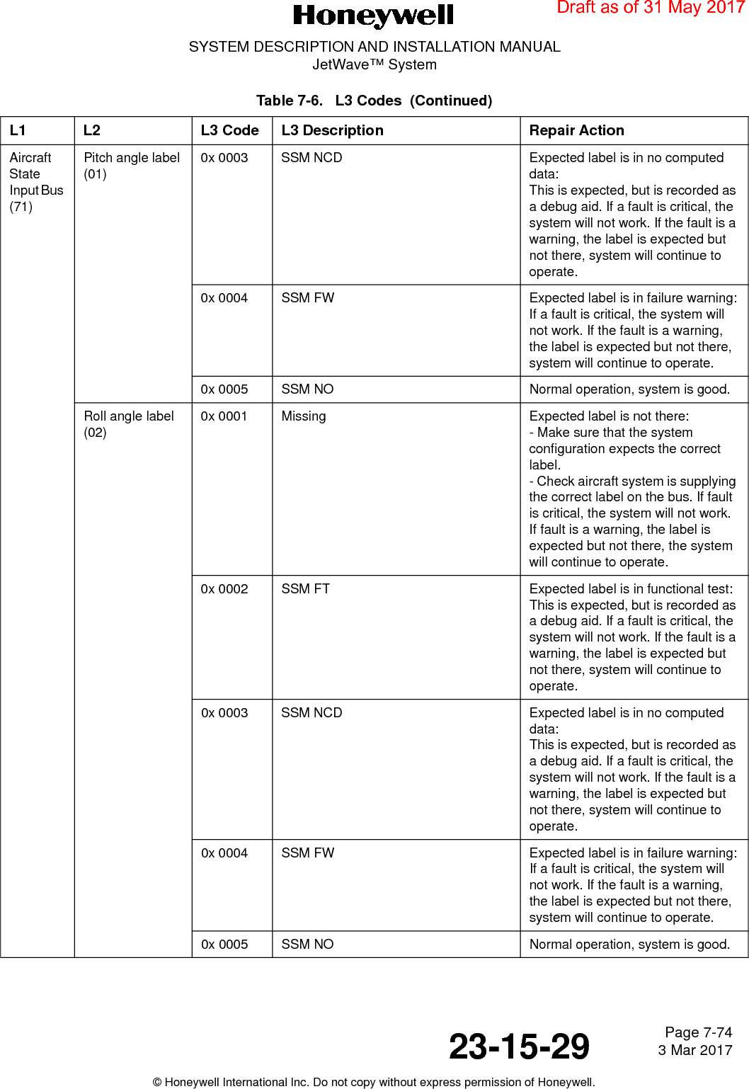
User Manual_Part 6
User Manual_Part 6
Navigation menu
Upload a User Manual
Namespaces
Wiki Guide
HTML
PDF
Info
Views
User Manual
Discussion / Help
Navigation