EMS Technologies Canada JETWAVE2 Jetwave User Manual 23 15 29R004
EMS Technologies Canada, Ltd. Jetwave 23 15 29R004
Contents
User Manual_Part 6
SYSTEM DESCRIPTION AND INSTALLATION MANUAL
JetWave™ System
Page 4-131
3 Mar 2017
© Honeywell International Inc. Do not copy without express permission of Honeywell.
23-15-29
Figure 4-36. (Sheet 8 of 8) JetWave™ System Interconnect Diagram - FMA (KRFU Outside Aircraft Fuselage), (90401047-1, REV F)
Draft as of 31 May 2017
SYSTEM DESCRIPTION AND INSTALLATION MANUAL
JetWave™ System
Page 4-132
3 Mar 2017
© Honeywell International Inc. Do not copy without express permission of Honeywell.
23-15-29
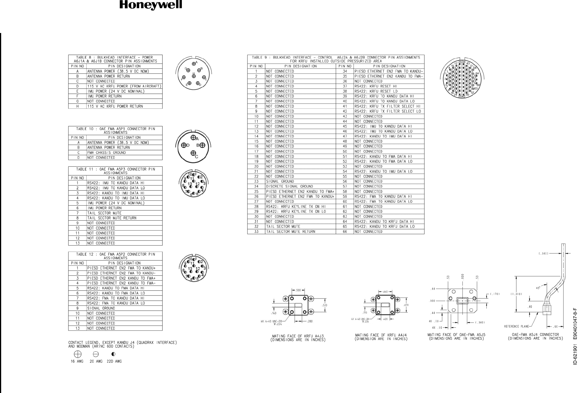
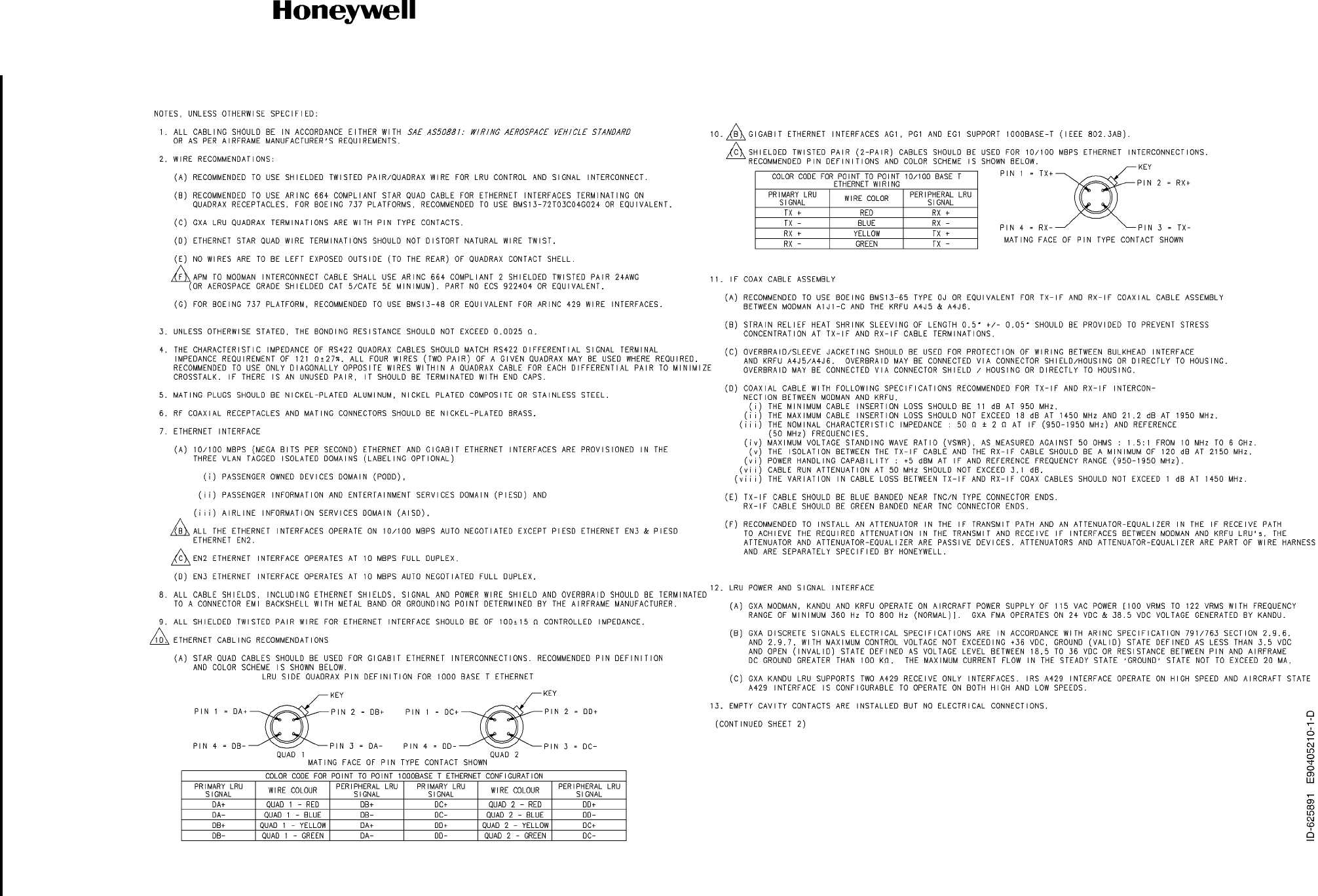
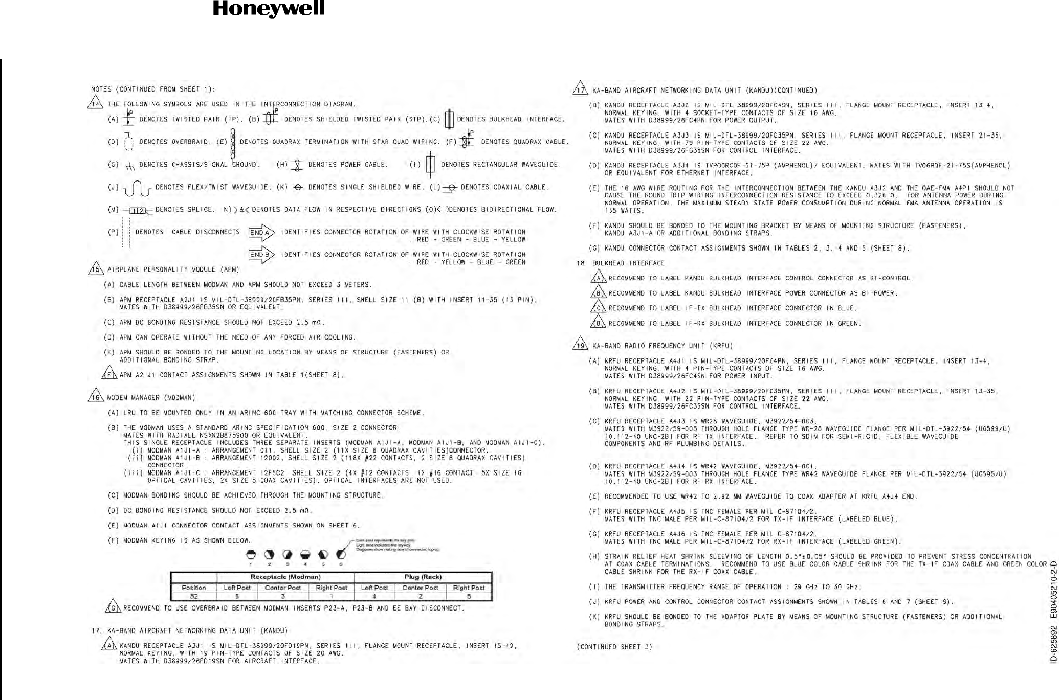
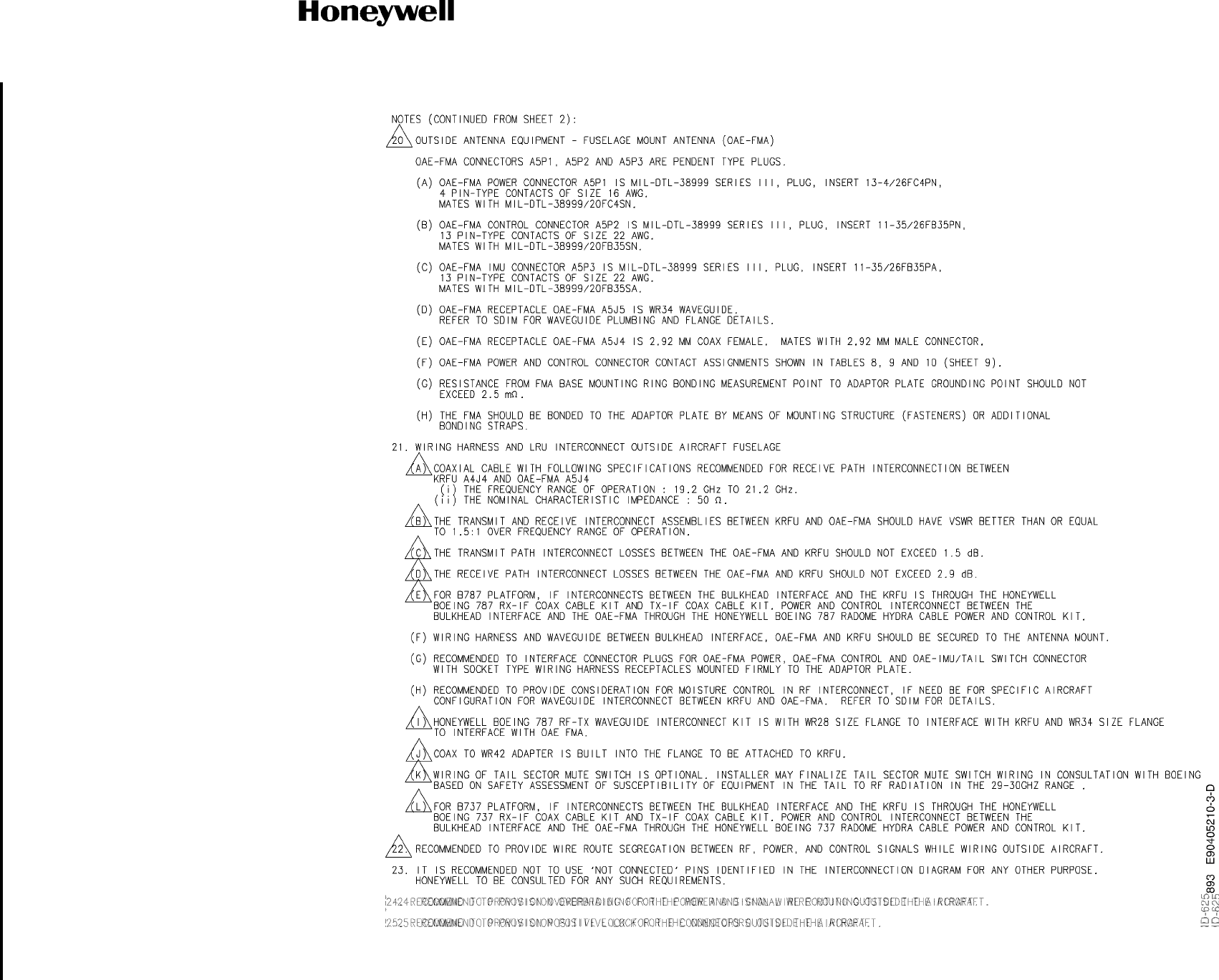
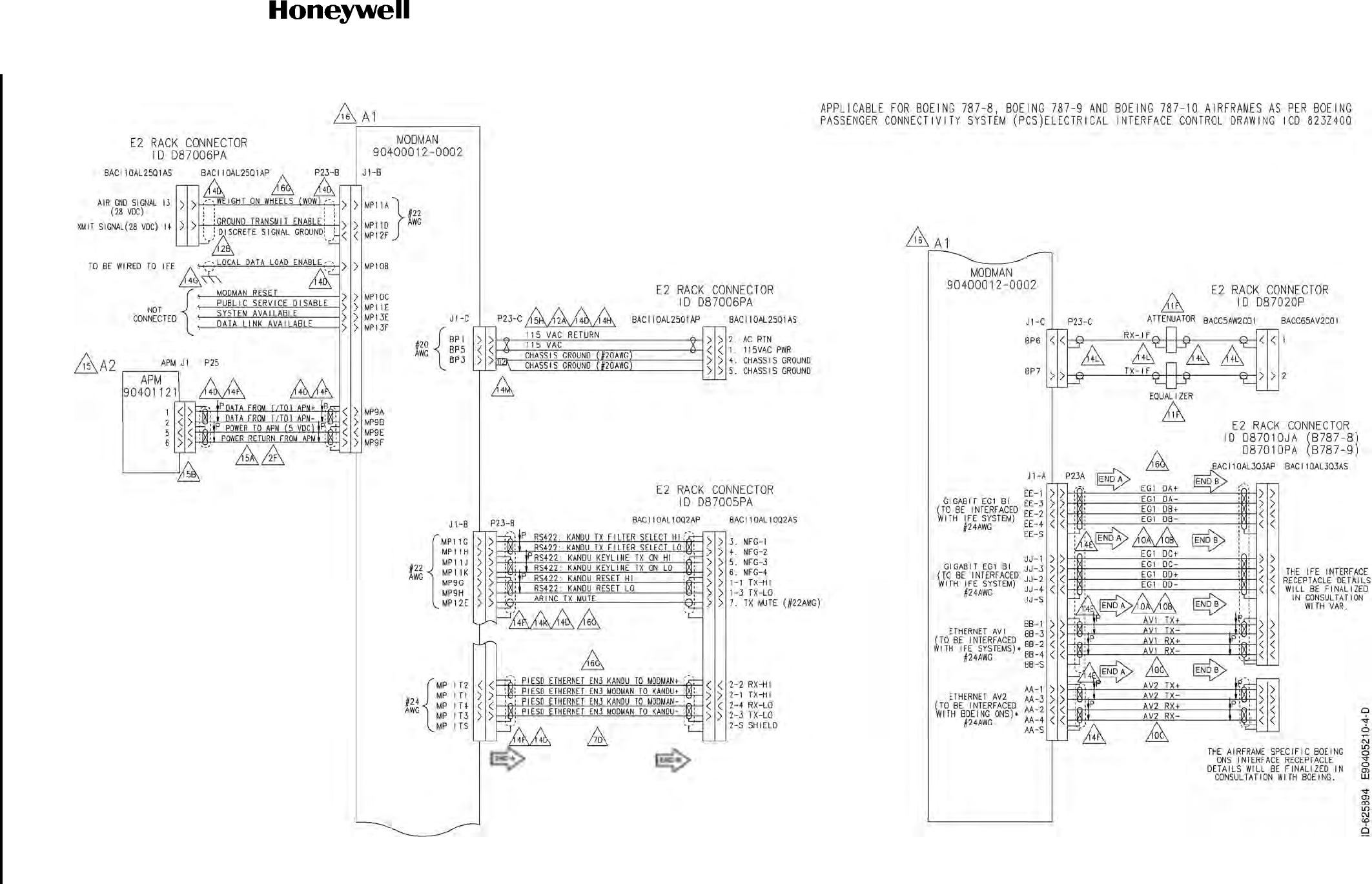
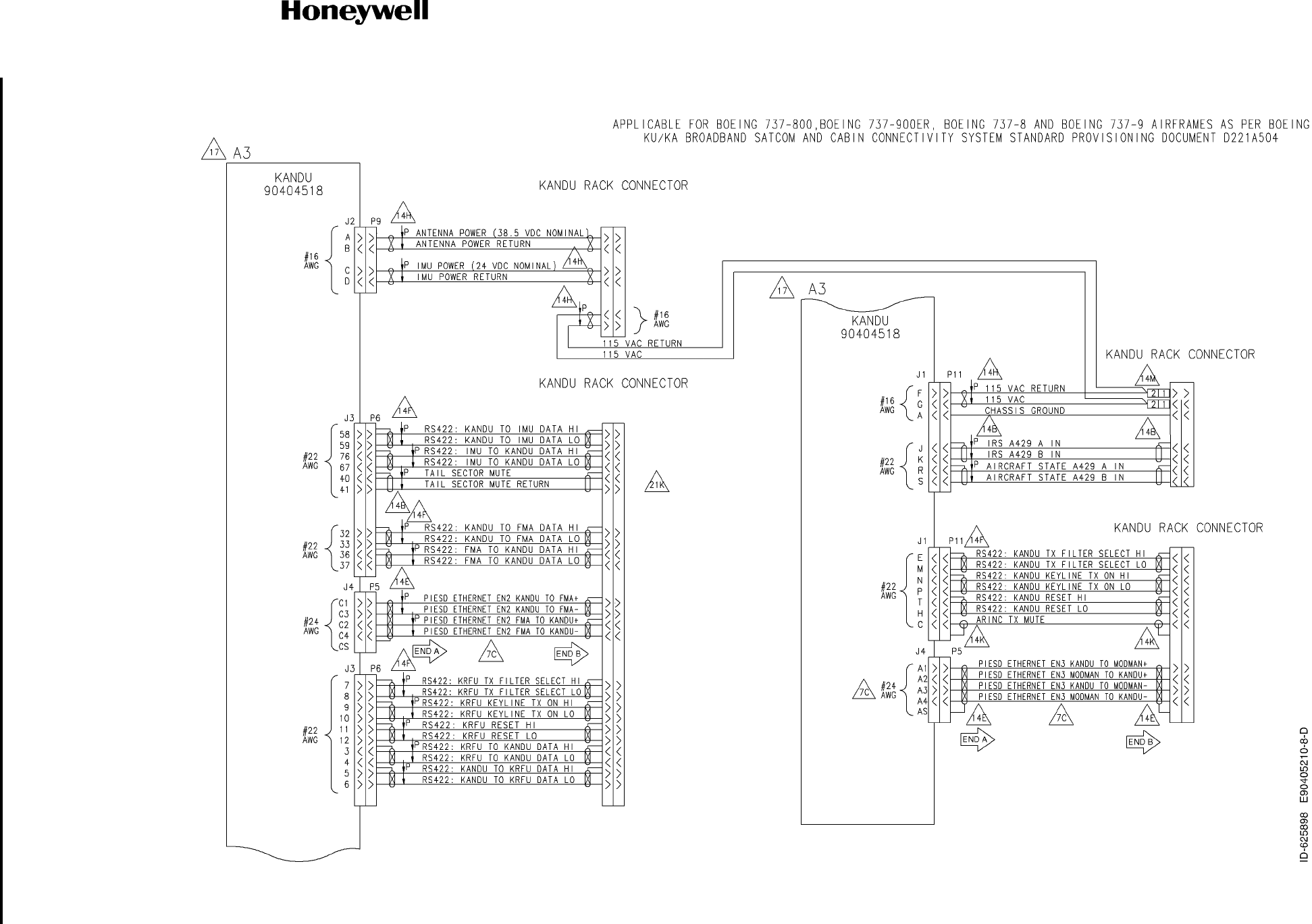
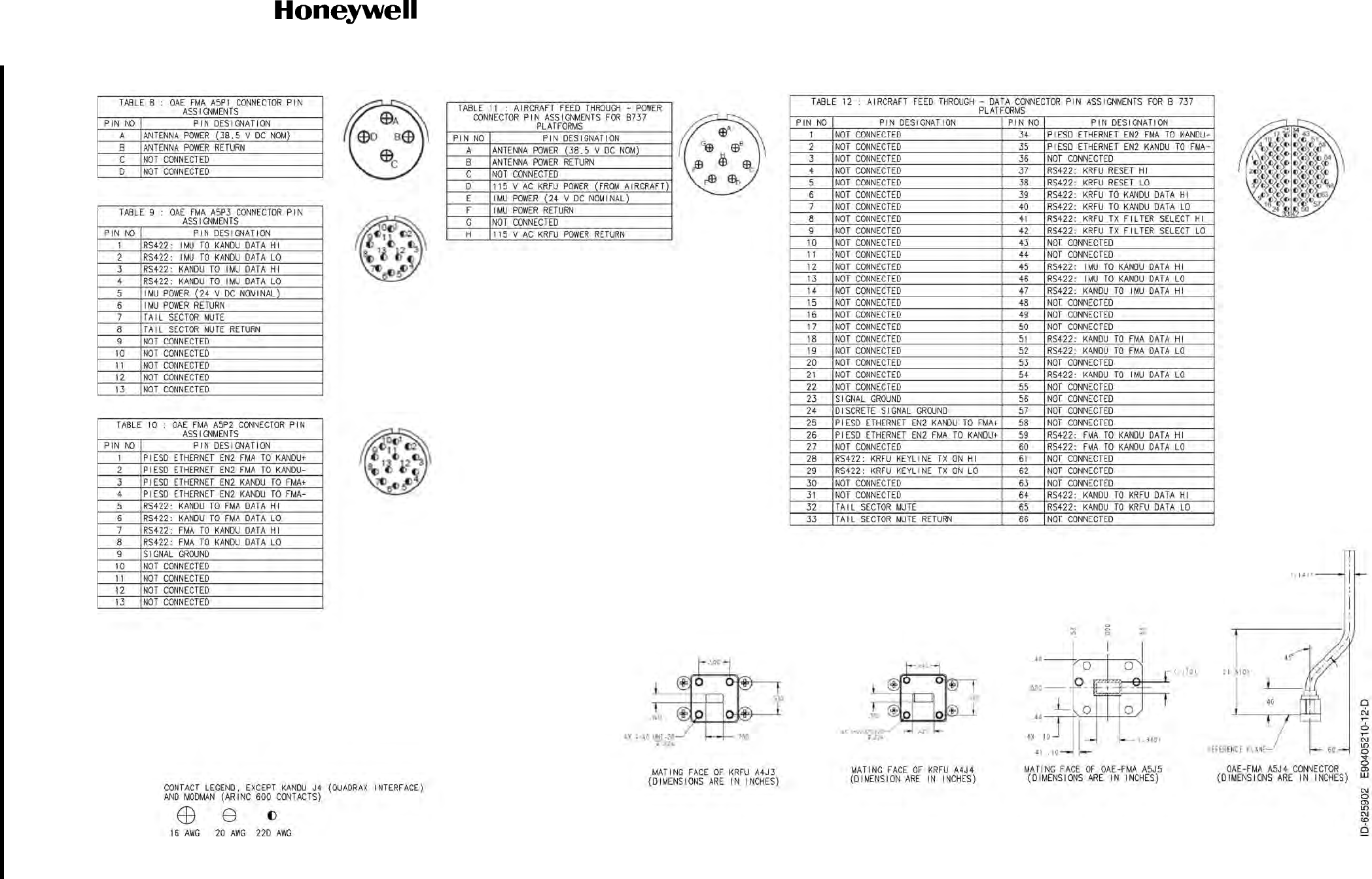
Figure 4-37. (Sheet 1 of 12) Alternative KRFU Outside Aircraft Fuselage Configuration (90405210, REV D)
Draft as of 31 May 2017
SYSTEM DESCRIPTION AND INSTALLATION MANUAL
JetWave™ System
Page 4-133
3 Mar 2017
© Honeywell International Inc. Do not copy without express permission of Honeywell.
23-15-29
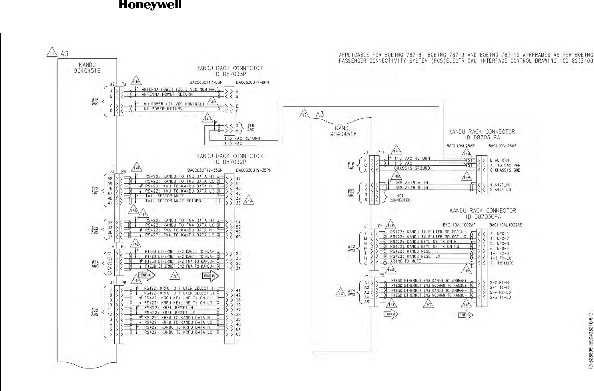
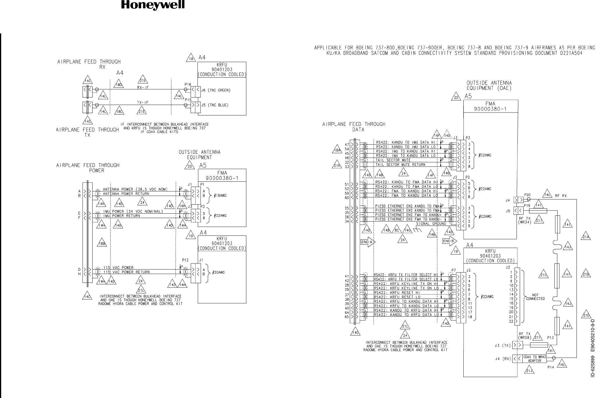
Figure 4-37. (Sheet 2 of 12) Alternative KRFU Outside Aircraft Fuselage Configuration (90405210, REV D)
Draft as of 31 May 2017
SYSTEM DESCRIPTION AND INSTALLATION MANUAL
JetWave™ System
Page 4-134
3 Mar 2017
© Honeywell International Inc. Do not copy without express permission of Honeywell.
23-15-29
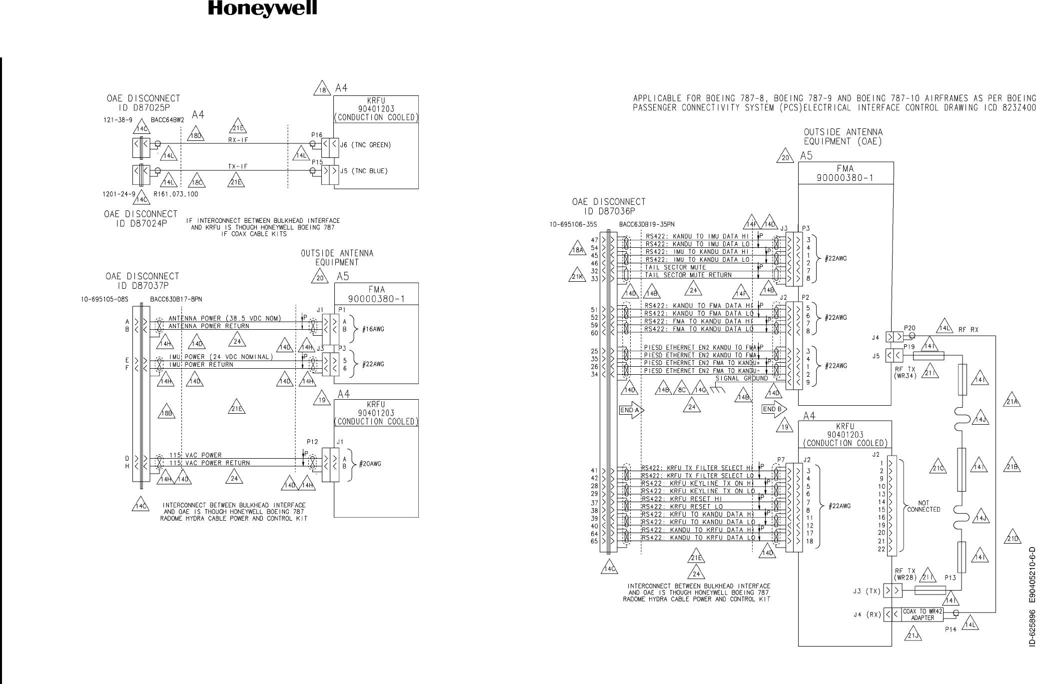
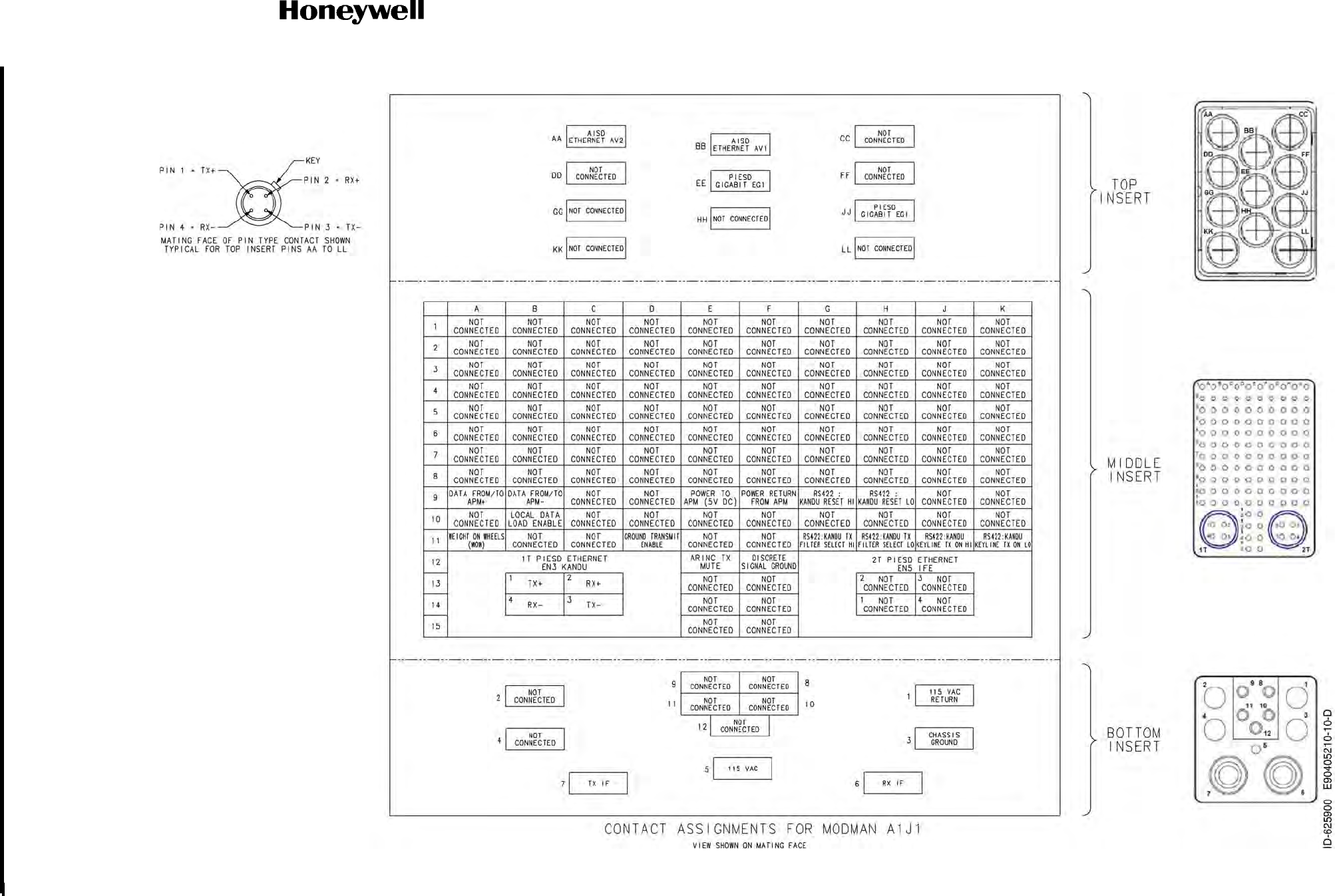
Figure 4-37. (Sheet 3 of 12) Alternative KRFU Outside Aircraft Fuselage Configuration (90405210, REV D)
Draft as of 31 May 2017
SYSTEM DESCRIPTION AND INSTALLATION MANUAL
JetWave™ System
Page 4-135
3 Mar 2017
© Honeywell International Inc. Do not copy without express permission of Honeywell.
23-15-29
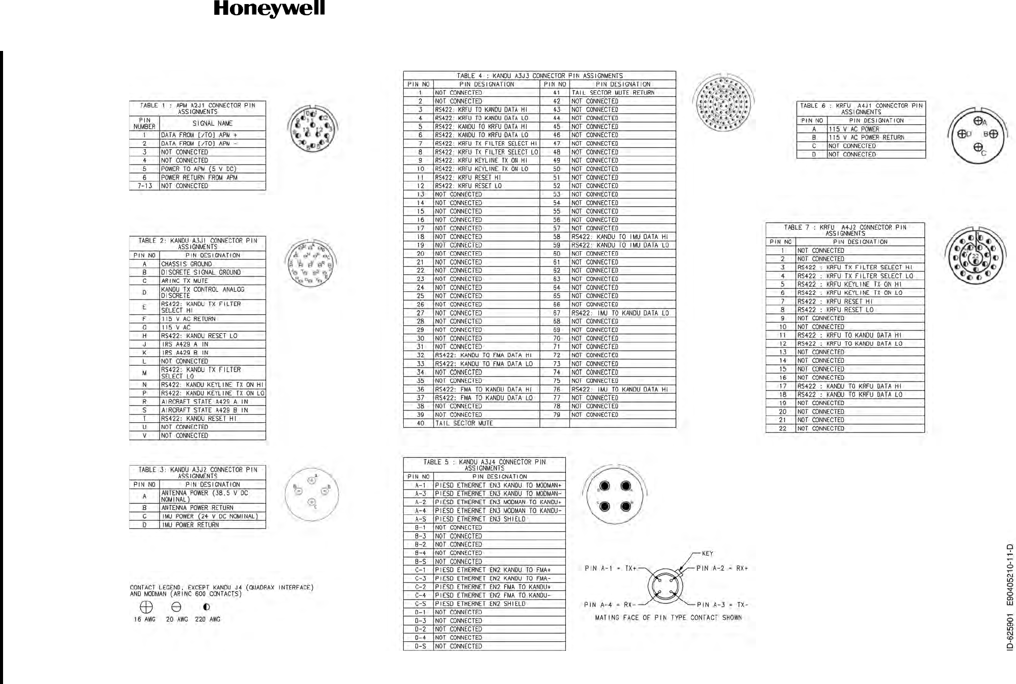
Figure 4-37. (Sheet 4 of 12) Alternative KRFU Outside Aircraft Fuselage Configuration (90405210, REV D)
Draft as of 31 May 2017
SYSTEM DESCRIPTION AND INSTALLATION MANUAL
JetWave™ System
Page 4-136
3 Mar 2017
© Honeywell International Inc. Do not copy without express permission of Honeywell.
23-15-29
Figure 4-37. (Sheet 5 of 12) Alternative KRFU Outside Aircraft Fuselage Configuration (90405210, REV D)
Draft as of 31 May 2017
SYSTEM DESCRIPTION AND INSTALLATION MANUAL
JetWave™ System
Page 4-137
3 Mar 2017
© Honeywell International Inc. Do not copy without express permission of Honeywell.
23-15-29
Figure 4-37. (Sheet 6 of 12) Alternative KRFU Outside Aircraft Fuselage Configuration (90405210, REV D)
Draft as of 31 May 2017
SYSTEM DESCRIPTION AND INSTALLATION MANUAL
JetWave™ System
Page 4-138
3 Mar 2017
© Honeywell International Inc. Do not copy without express permission of Honeywell.
23-15-29
Figure 4-37. (Sheet 7 of 12) Alternative KRFU Outside Aircraft Fuselage Configuration (90405210, REV D)
Draft as of 31 May 2017
SYSTEM DESCRIPTION AND INSTALLATION MANUAL
JetWave™ System
Page 4-139
3 Mar 2017
© Honeywell International Inc. Do not copy without express permission of Honeywell.
23-15-29
Figure 4-37. (Sheet 8 of 12) Alternative KRFU Outside Aircraft Fuselage Configuration (90405210, REV D)
Draft as of 31 May 2017
SYSTEM DESCRIPTION AND INSTALLATION MANUAL
JetWave™ System
Page 4-140
3 Mar 2017
© Honeywell International Inc. Do not copy without express permission of Honeywell.
23-15-29
Figure 4-37. (Sheet 9 of 12) Alternative KRFU Outside Aircraft Fuselage Configuration (90405210, REV D)
Draft as of 31 May 2017
SYSTEM DESCRIPTION AND INSTALLATION MANUAL
JetWave™ System
Page 4-141
3 Mar 2017
© Honeywell International Inc. Do not copy without express permission of Honeywell.
23-15-29
Figure 4-37. (Sheet 10 of 12) Alternative KRFU Outside Aircraft Fuselage Configuration (90405210, REV D)
Draft as of 31 May 2017
SYSTEM DESCRIPTION AND INSTALLATION MANUAL
JetWave™ System
Page 4-142
3 Mar 2017
© Honeywell International Inc. Do not copy without express permission of Honeywell.
23-15-29
Figure 4-37. (Sheet 11 of 12) Alternative KRFU Outside Aircraft Fuselage Configuration (90405210, REV D)
Draft as of 31 May 2017
SYSTEM DESCRIPTION AND INSTALLATION MANUAL
JetWave™ System
Page 4-143
3 Mar 2017
© Honeywell International Inc. Do not copy without express permission of Honeywell.
23-15-29
Figure 4-37. (Sheet 11 of 12) Alternative KRFU Outside Aircraft Fuselage Configuration (90405210, REV D
Draft as of 31 May 2017

SYSTEM DESCRIPTION AND INSTALLATION MANUAL
JetWave™ System
Page 4-144
3 Mar 2017
© Honeywell International Inc. Do not copy without express permission of Honeywell.
23-15-29
Blank Page
Draft as of 31 May 2017

Page 5-1
3 Mar 2017
23-15-29
SYSTEM DESCRIPTION AND INSTALLATION MANUAL
JetWave™ System
© Honeywell International Inc. Do not copy without express permission of Honeywell.
SECTION 5
SOFTWARE CONFIGURATION
5.1 ARINC 615A Software Data Load Process
A. Introduction
As a minimum, APM system configuration files need to be loaded onto the JETWAVE™ system.
The JetWave™ LRUs are preloaded with a full software load and there may be a need to perform
a field data load under normal conditions during installation. If a new software release is desired by
means of a Service Bulletin, or if all of the LRUs are not at the same software release level, then a
new data load will be required.
On completion of physical installation and interconnection of JetWave™ LRUs in the aircraft, it is
to be verified that the appropriate version of the JetWave™ LRU operational data and APM
configuration file is data loaded onto the JetWave™ LRUs.
Whenever an LRU is exchanged in a JETWAVE™ System, confirmation is required to make sure
that the replacement LRU contains software that is compatible with the software configuration of
the other boxes. The software upgrade procedures must be rerun for that particular LRU each time
an LRU is replaced, to make sure there is compatibility within the JETWAVE™ System.
The JETWAVE™ System does not allow for any mix of Honeywell and non-Honeywell furnished
LRUs.
The JetWave™ LRU operational data files are available from the Honeywell Portal. The software
data load can be carried out when the data load files are issued separately along with Service
Bulletins for any in-service system updates.
Only Honeywell approved software is loadable onto JetWave™ LRUs.
This section of the document supplies information on how to accomplish ARINC 615A data loading
of JetWave™ system in the field.
The data loading of JetWave™ system is done while the aircraft is on ground. During the data load,
there will not be any RF transmission.
B. System Requirements
For data load, the data loader is to be interfaced with Modman through the ARINC 600 Modman
AV1 Ethernet port unless APM configuration does specify other port / IPs settings. The AES
JetWave™ Modman is designed to enter into data load mode when the discrete signal interface for
Data load Enable is asserted (grounded) by ARINC 615A compliant data loading utility. The
discrete input electrical specification is in accordance with the specification in ARINC 763 Section
2.9.6.
It is recommended that the Modman AV1 Maintenance port and Modman Data Load Enable
discrete interface be wired for JetWave™ AES data load and AES log extraction.
An ARINC 615A compliant data loading utility is recommended to be used for JetWave™ AES data
loading. The data loading software-based utility may be hosted on a PC architecture device such
Draft as of 31 May 2017

Page 5-2
3 Mar 2017
23-15-29
SYSTEM DESCRIPTION AND INSTALLATION MANUAL
JetWave™ System
© Honeywell International Inc. Do not copy without express permission of Honeywell.
as an Electronic Flight Bag (EFB) or other portable computing device, an on-board portable device,
or an avionics device. Since the Aircraft loading procedures can vary due to different type of
uploading means, it is recommended to refer to the appropriate Aircraft Maintenance Manual before
attempting data loading of JetWave™ AES system.
C. Overview
This section contains the instructions for data loading of JetWave™ software to any of the
JetWave™ LRUs through the Ethernet interface maintenance port of Modman. Data loading of
JetWave™ system can be performed while:
• JetWave™ system is in normal operation
• During system initialization
• When in AES Critical Fault Mode.
The maintenance operator is responsible for determining which loads are presented to the
JetWave™ AES system through the Modman for data load. JetWave™ AES system in turn will
determine the files required to meet the data load request.
The JetWave™ AES system data loading of all LRUs including uploading of the AES configuration
data can be performed through Modman. For data load purpose, Modman acts as a gateway to
JetWave™ LRUs and LRUs themselves do the data load. It is not recommended to attempt field
data loading JetWave™ LRUs other than through the Modman.
The system configuration files are stored in nonvolatile memory in the APM and does not lose its
contents due to loss of APM power.
Upon transfer of the loaded software, the Modman makes sure that the software presented by the
data loader has been loaded correctly before responding that the load is complete and will report
part numbers of the loaded software.
For illustration purposes, snap shots of the AIT make F-SIM-LDR ARINC 615A data loader
simulator are included within this document.
(1) Parts Needed:
•Data load files from the Honeywell Portal.
•ARINC 615A compliant data. The JetWave™ AES system software is loaded through the
Modman loader.
NOTE: The JetWave™ AES loadable software part, part number varies for each release.
(2) System Software/Database Updates
Under normal circumstances, time required to carry out data load operation of all JetWave™
AES LRUs can be performed within a total time of between 1.0 and 2.25 hours. This includes
the Modman, KANDU, and antenna. Installation for the FMA takes significantly less time than
for the TMA.
The data sets as shown in Table 5-1 can be transferred through the data load port of the
Modman.
Draft as of 31 May 2017

Page 5-3
3 Mar 2017
23-15-29
SYSTEM DESCRIPTION AND INSTALLATION MANUAL
JetWave™ System
© Honeywell International Inc. Do not copy without express permission of Honeywell.
:
In the above listing, upload is defined as the transfer of a data set from the ARINC 615A data
loader and a download is defined as the transfer of a data set from Modman to the ARINC
615A data loader. For JetWave™ AES LRUs where data download operation is not
supported, the system will return 0x1002 status code.
The ARINC 665 data load package includes *.LUM files for each of JetWave™ LRUs. This
along with LOADS.LUM and FILES.LUM are assembled to form a 665 package which include
a manifest file as a compressed file format. The ARINC 665 data load set for the JetWave™
system comprises of:
• LOADS.LUM: Describes the loads that the data load device carries, one or more.
• FILES.LUM: Lists all the files, excluding itself, on the data load.
• *.LUH is the load part index file that LOADS.LUM points to.
• *.LUP is the data file which contains compressed software image/images and manifest
files.
During the data loading process, the respective LRU unzips the file and extracts the manifest
file and the images. Each LRU identifies the part for itself from the manifest file.
The .LUP files that follow are included as part of ARINC665 data load file for different AES
LRUs.
• Modman operational data
• AES configuration data
• KRFU operational image
• KANDU operational image
• OAE-TMA operational image
• OAE- FMA operational image.
NOTE: More than one CONFIG sub parts may be present in a configuration load, one per
AES configuration file type.
Table 5-1. Data Sets
LRU Data Set Transfer Process
Modman JetWave™ Modman LRU Operational
file Upload only
APM APM configuration file Upload only through the Modman
KANDU JetWave™ KANDU LRU operational file Upload only through the Modman
KRFU JetWave™ KRFU LRU operational file Upload only through the Modman
OAE-FMA
or
OAE-TMA
JetWave™ OAE LRU operational file Upload only through the Modman
Draft as of 31 May 2017
Page 5-4
3 Mar 2017
23-15-29
SYSTEM DESCRIPTION AND INSTALLATION MANUAL
JetWave™ System
© Honeywell International Inc. Do not copy without express permission of Honeywell.
For the ARINC 615A data load operations, an A615A target connection must be defined.
Target connection defines a TFTP client on the Modman and TFTP server on the data loader
that will be used for file transfer.
D. Procedure (AIT Flight Simulyzer v3.0.0)
(1) Refer to the latest revision of SBs JETWAVE-23-0001, JETWAVE-23-0002, and
JETWAVE-23-0003 or later SB for the software upload procedures.
(2) Setup
NOTE: These setup steps must be run each time the Data Loader application is closed and
opened again.
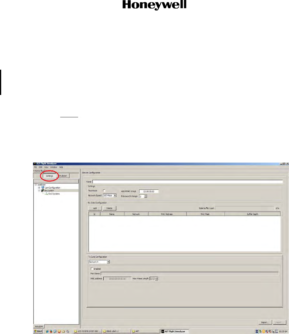
(a) Open the AIT ‘Flight Simulyzer’ application.
(b) Select the “Settings” button on the left side of the screen.
Draft as of 31 May 2017
Page 5-5
3 Mar 2017
23-15-29
SYSTEM DESCRIPTION AND INSTALLATION MANUAL
JetWave™ System
© Honeywell International Inc. Do not copy without express permission of Honeywell.
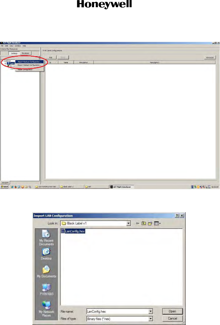
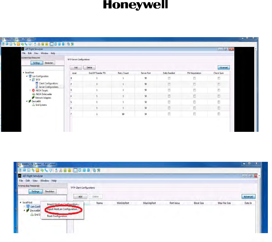
(c) Right click “Lan Configuration” and select “Import HostLan Configuration…”
(d) Browse to the “LanConfig.hex” file and select “Open”. (This file needs to be present by
the installer on the data loader computer.)
Draft as of 31 May 2017
Page 5-6
3 Mar 2017
23-15-29
SYSTEM DESCRIPTION AND INSTALLATION MANUAL
JetWave™ System
© Honeywell International Inc. Do not copy without express permission of Honeywell.
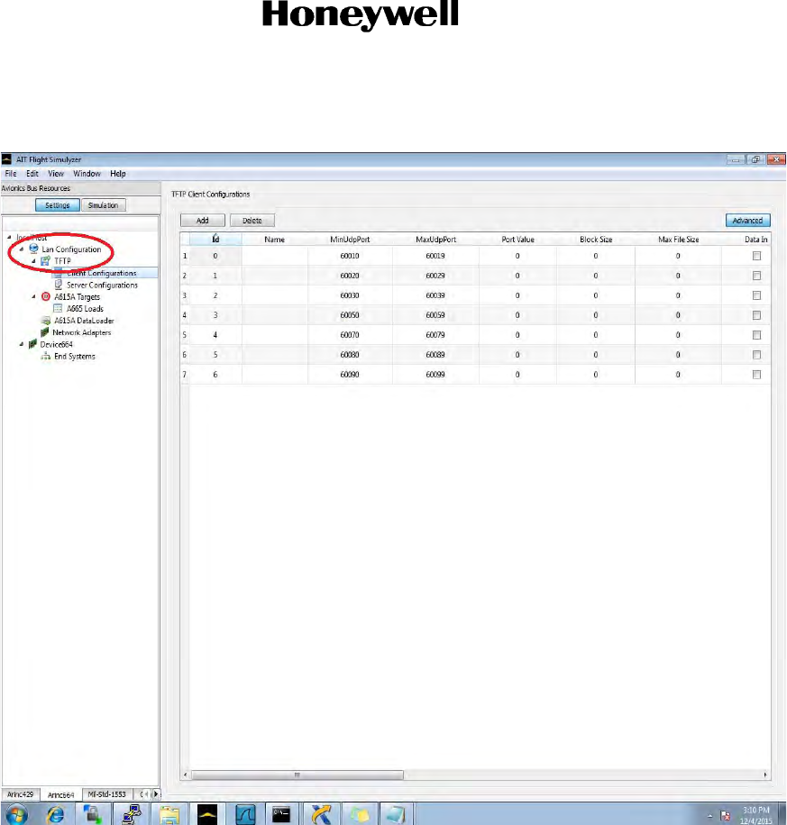
(e) Expand “Lan Configurations” and then also expand “TFTP” on the left side of the screen.
Draft as of 31 May 2017
Page 5-7
3 Mar 2017
23-15-29
SYSTEM DESCRIPTION AND INSTALLATION MANUAL
JetWave™ System
© Honeywell International Inc. Do not copy without express permission of Honeywell.
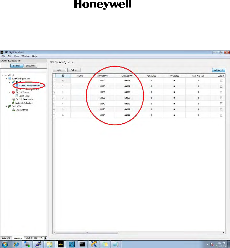
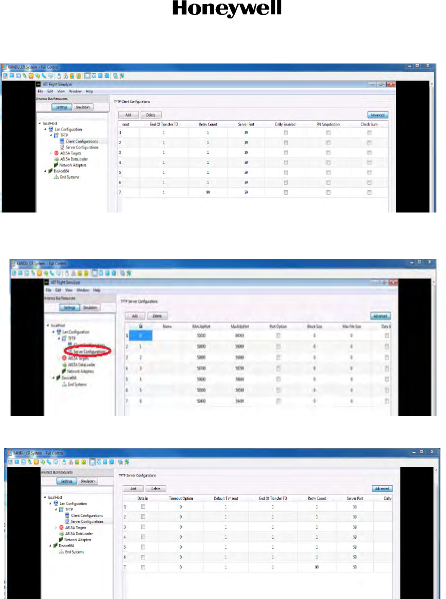
(f) Select “Client Configurations” on the left side of the screen and verify the settings appear
as in the screenshot below.
Draft as of 31 May 2017
Page 5-8
3 Mar 2017
23-15-29
SYSTEM DESCRIPTION AND INSTALLATION MANUAL
JetWave™ System
© Honeywell International Inc. Do not copy without express permission of Honeywell.
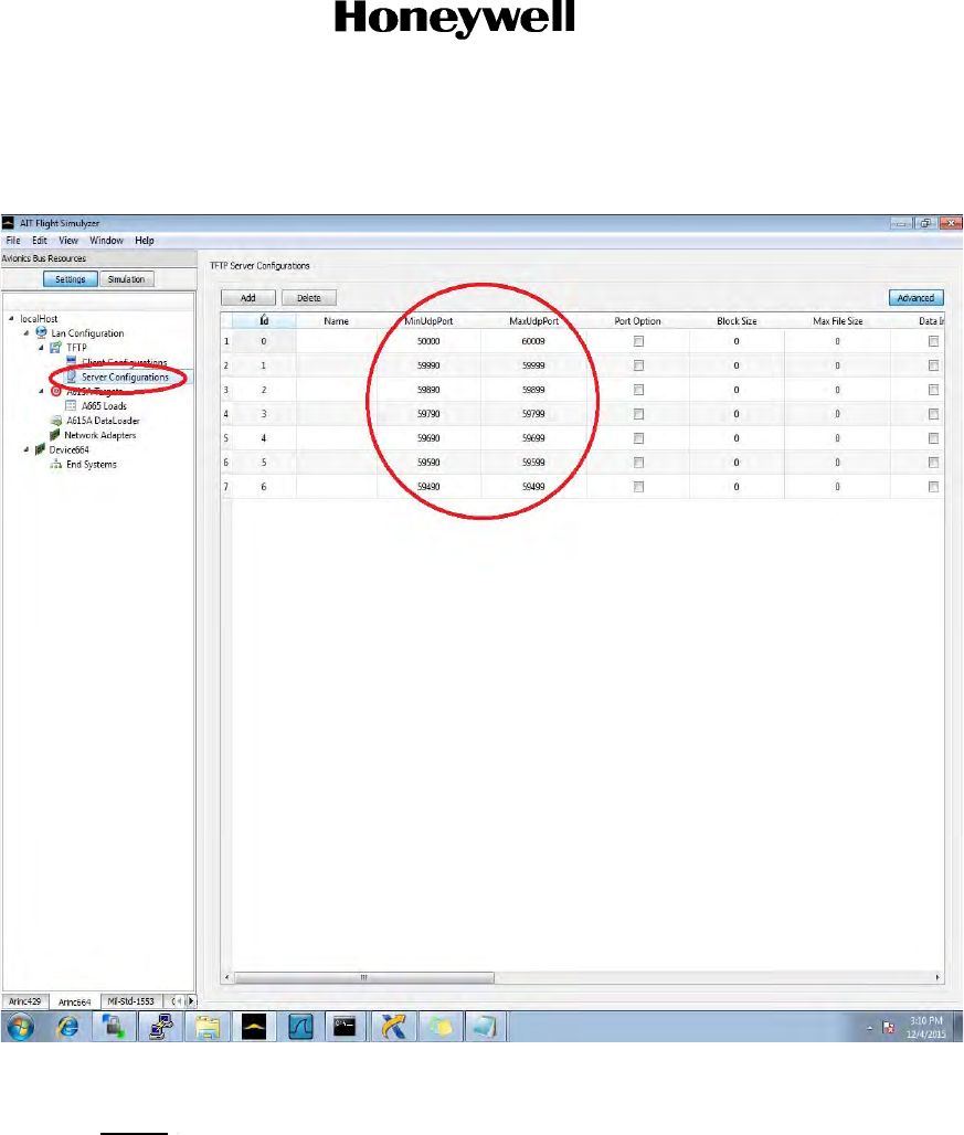
(g) Select “Server Configurations” on the left side of the screen and verify the settings
appear as in the screenshot below.
(3) Data-loading GXA with the AIT Flight Simulyzer Software
NOTE: Replace “<LRU NAME>” below with the LRU to be loaded.
(a) Power on the system.
(b) Wait until the Modman front panel LEDs (‘POWER’ and ‘STATUS’) are both solid green
in color. This would indicate the system is in “Normal Operation” mode. If the MM does
not get to a solid green color, then that should be investigated before the SW upload
process begins.
(c) Make sure that the ‘Data Load Enable’ discrete is set to the ‘Enabled’ state.
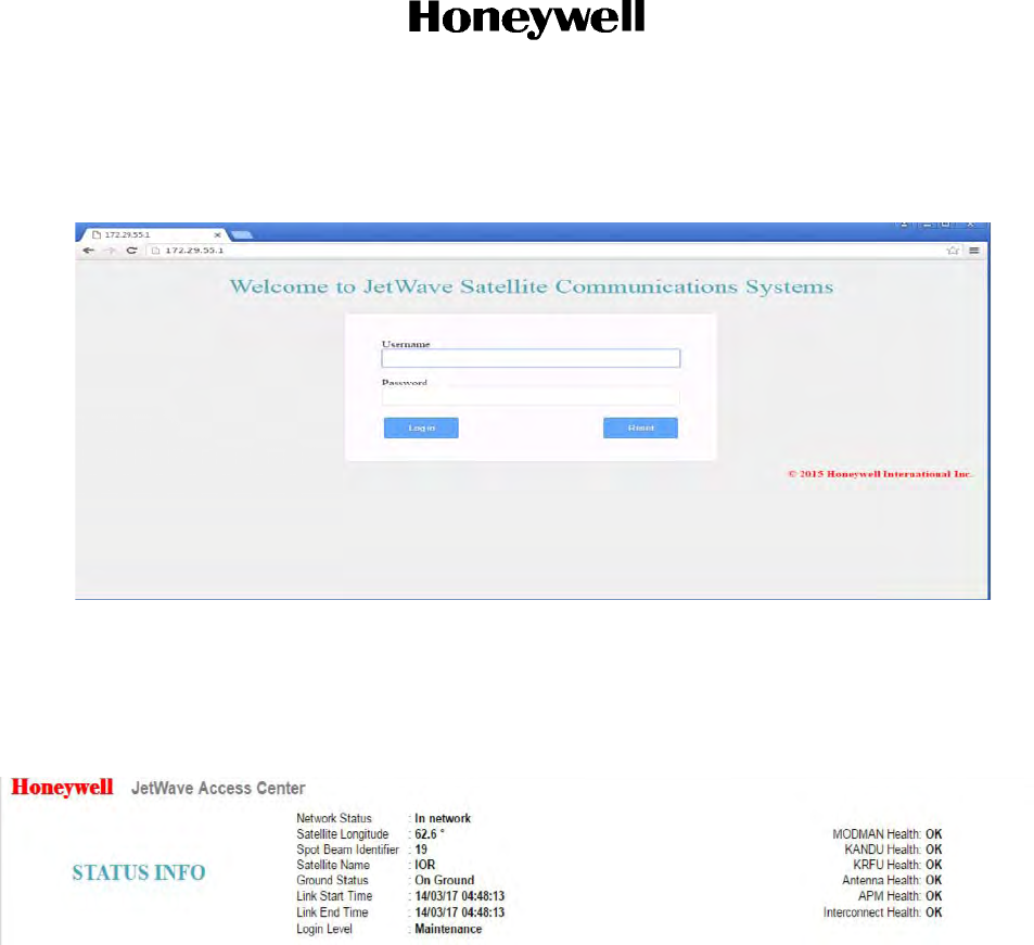
(d) On the installers data load PC, open a web browser and in the location bar enter IP
address 172.29.55.1, hit enter. This will open the AES GUI as shown in the figure below.
Draft as of 31 May 2017
Page 5-9
3 Mar 2017
23-15-29
SYSTEM DESCRIPTION AND INSTALLATION MANUAL
JetWave™ System
© Honeywell International Inc. Do not copy without express permission of Honeywell.
Log in and view the system status info at the top of the GUI window. At the GUI login,
the username is "User" and there is no password.
(e) Wait until all of the LRUs indicate a status of “OK” before continuing, to ensure the
system has booted up fully. Should the GX system come up in “Init” mode or “Critical
Fault” mode, the data loader process may still be performed to update the software if the
cause was known to be related to the previous version software. Otherwise, the system
fault should be investigated and a “Normal Operation” state restored.
Draft as of 31 May 2017
Page 5-10
3 Mar 2017
23-15-29
SYSTEM DESCRIPTION AND INSTALLATION MANUAL
JetWave™ System
© Honeywell International Inc. Do not copy without express permission of Honeywell.
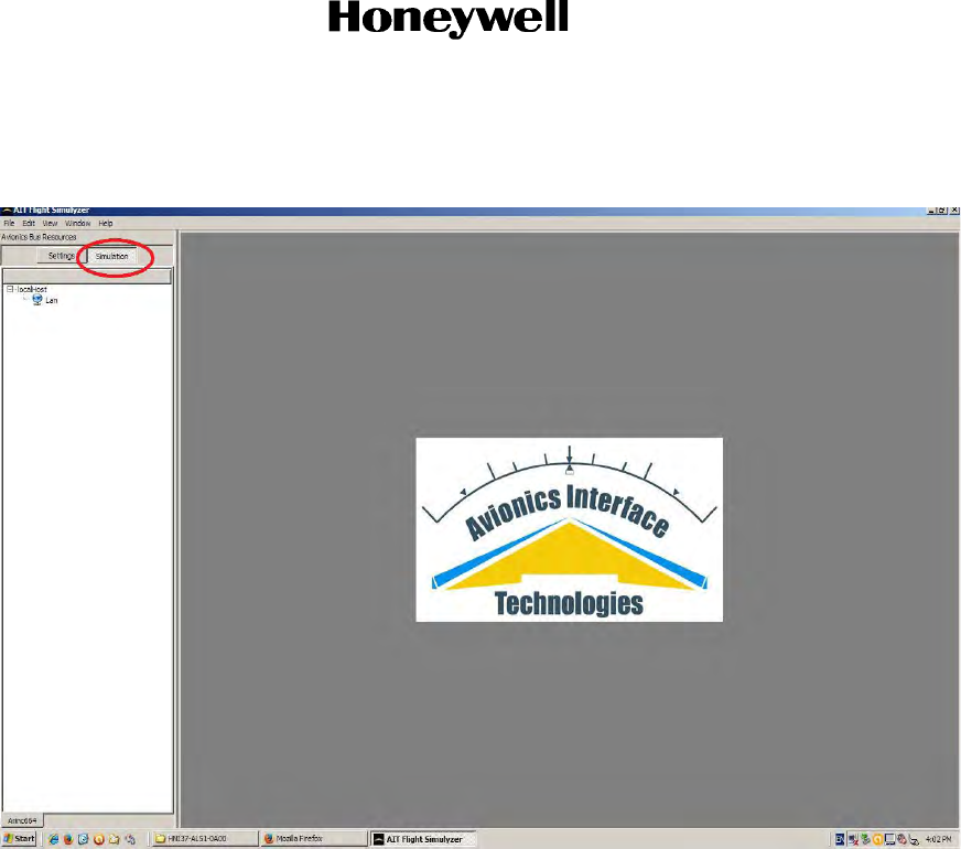
(f) In the AIT ‘Flight Simulyzer’ application, select the “Simulation” button on the left side of
the screen.
Draft as of 31 May 2017
Page 5-11
3 Mar 2017
23-15-29
SYSTEM DESCRIPTION AND INSTALLATION MANUAL
JetWave™ System
© Honeywell International Inc. Do not copy without express permission of Honeywell.
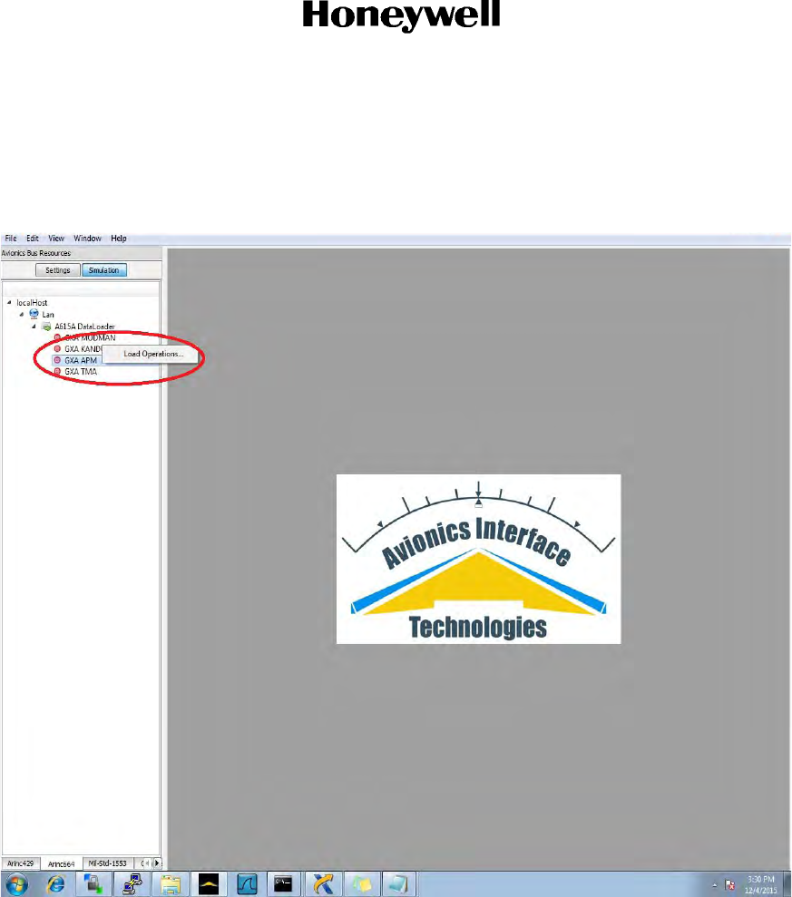
(g) The LRU name (i.e. ‘GXA <LRU NAME>’) should now be visible in the left side window
pane under “A615A Data Loader”.
(h) Right click the LRU name (‘GXA <LRU NAME>’) on the left side window pane and select
“Load Operations…”
Draft as of 31 May 2017
Page 5-12
3 Mar 2017
23-15-29
SYSTEM DESCRIPTION AND INSTALLATION MANUAL
JetWave™ System
© Honeywell International Inc. Do not copy without express permission of Honeywell.
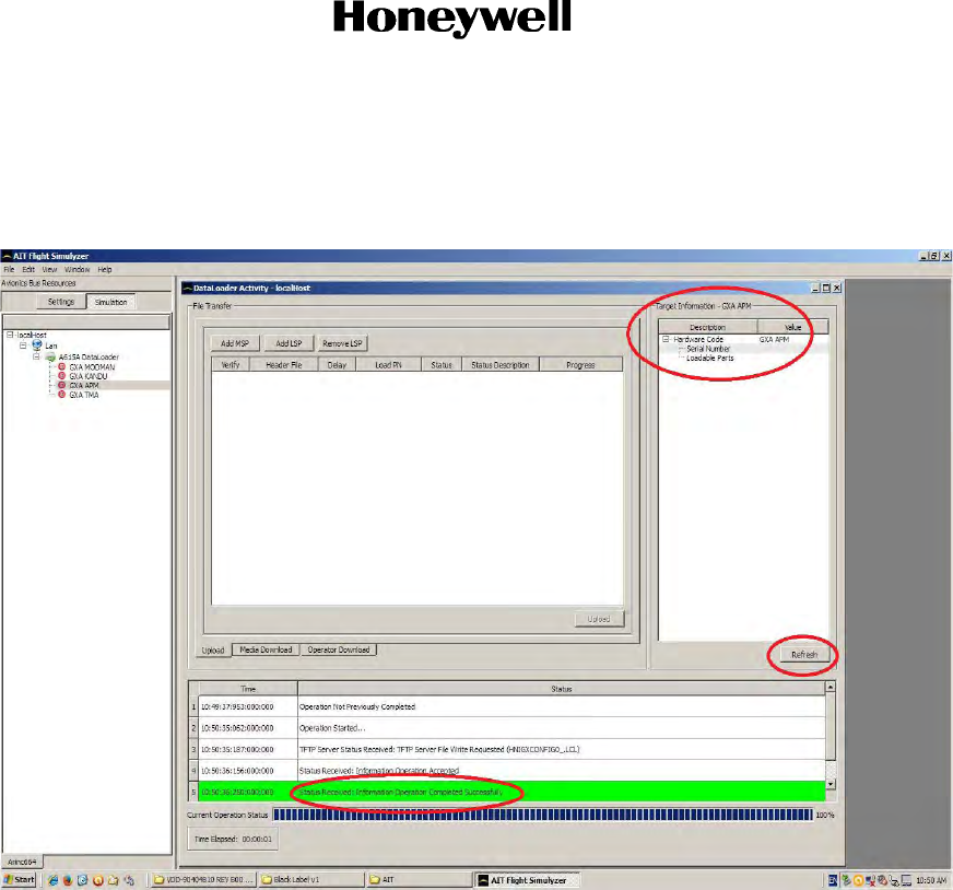
(i) Select the “Refresh” button near the bottom right part of the screen.
(j) Verify that the “Target Information” for the LRU appears on the right side of the screen.
This will ensure communication between the 615A Data Loader and the Modman.
Draft as of 31 May 2017
Page 5-13
3 Mar 2017
23-15-29
SYSTEM DESCRIPTION AND INSTALLATION MANUAL
JetWave™ System
© Honeywell International Inc. Do not copy without express permission of Honeywell.
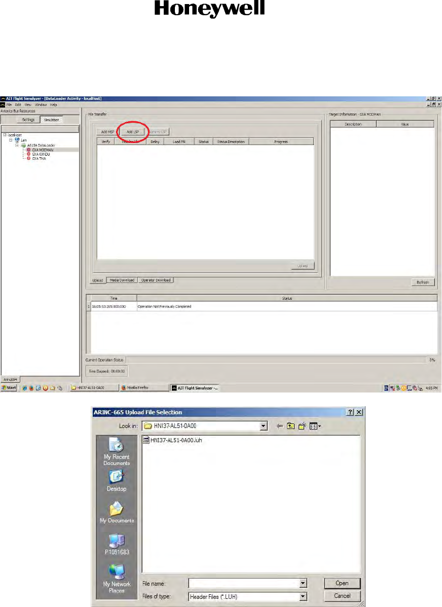
(k) Select “Add LSP…” and browse to the .luh file in the 665 data load package for the LRU,
select it and click “Open”.
Draft as of 31 May 2017
Page 5-14
3 Mar 2017
23-15-29
SYSTEM DESCRIPTION AND INSTALLATION MANUAL
JetWave™ System
© Honeywell International Inc. Do not copy without express permission of Honeywell.
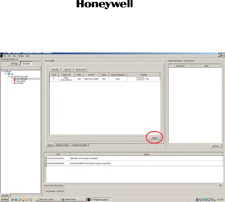
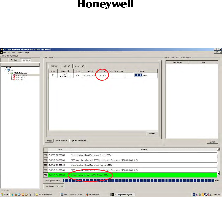
(l) The package should now be visible in the “File Transfer” window.
(m) Select the “Upload” button when ready to begin the transfer to the LRU.
(n) When complete, the “Status” heading in the “File Transfer” window will indicate
“Complete” and a green status bar at the bottom of the screen will indicate “Data load
Draft as of 31 May 2017
Page 5-15
3 Mar 2017
23-15-29
SYSTEM DESCRIPTION AND INSTALLATION MANUAL
JetWave™ System
© Honeywell International Inc. Do not copy without express permission of Honeywell.
has completed successfully. Once all LRUs are updated, de-assert the data load
discrete to reset the system (100%)”.
(o) If loading additional software, again execute the steps above starting with Step (h).
(p) Once all software upgrades are completed, toggle the ‘Data Load Enable’ discrete to the
‘Disabled’ state. This will cause a system reboot.
(q) On the data load PC, using a web browser (preferably Firefox or Chrome), point to IP
address ‘172.29.55.1’ in the browser to open the AES GUI as shown below. Log in and
view the system status info at the top of the GUI window. At the GUI login, the username
is "User" and there is no password.
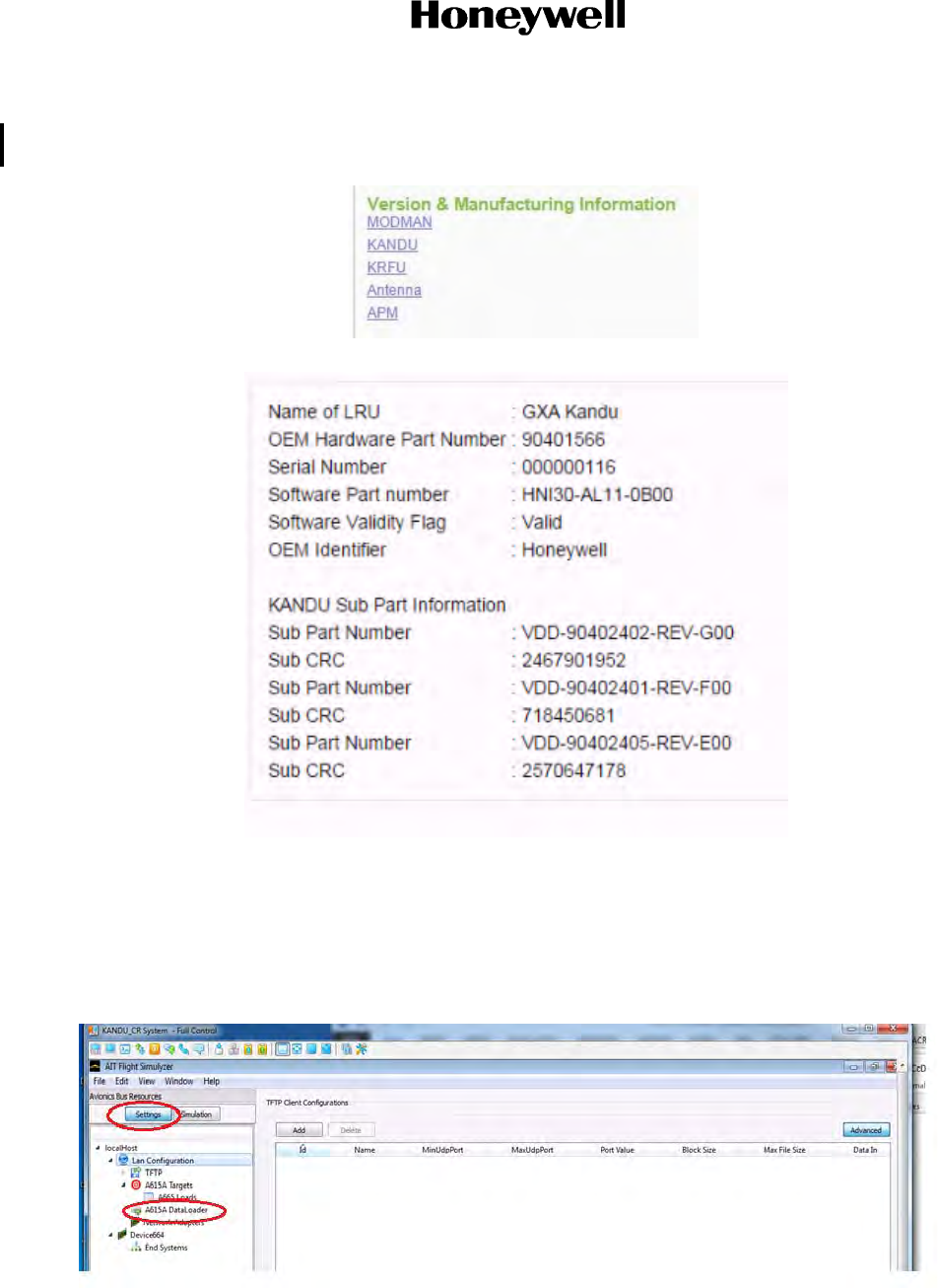
(r) Each LRU can be checked by selecting the respective LRU name under “Version &
Manufacturing Information”.
(s) Each LRU page will have the hardware part and serial numbers, as well as the software
part numbering information and CRCs for each sub part. This information should match
Draft as of 31 May 2017
Page 5-16
3 Mar 2017
23-15-29
SYSTEM DESCRIPTION AND INSTALLATION MANUAL
JetWave™ System
© Honeywell International Inc. Do not copy without express permission of Honeywell.
the VDDs which were loaded. For details on the software versions, refer to the
applicable SB.
E. A615 LanConfig.Hex File Creation and Settings
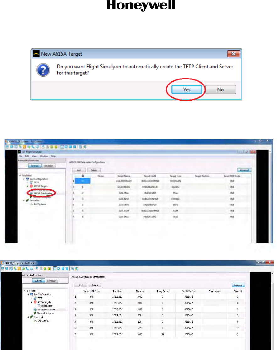
(1) Open the AIT Flight Simulyzer Tool and select the ‘Settings’ pushbutton. Under the local host
tree, select the “A615A DataLoader”. Select “ADD” to add the seven entries as shown in Step
(b). Each time you select “ADD,” you will be prompted to automatically create a TFTP Client
and Server for each target. Select “Yes”.
Draft as of 31 May 2017
Page 5-17
3 Mar 2017
23-15-29
SYSTEM DESCRIPTION AND INSTALLATION MANUAL
JetWave™ System
© Honeywell International Inc. Do not copy without express permission of Honeywell.
(2) Enter all the A615A DataLoader settings as shown in the following screenshots.
Draft as of 31 May 2017
Page 5-18
3 Mar 2017
23-15-29
SYSTEM DESCRIPTION AND INSTALLATION MANUAL
JetWave™ System
© Honeywell International Inc. Do not copy without express permission of Honeywell.
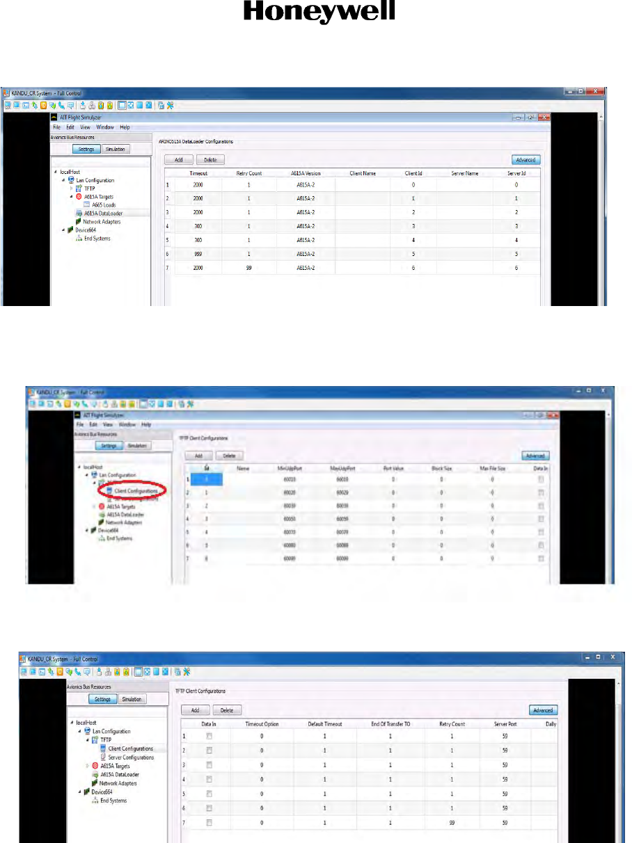
(3) In the Local Host Tree, select “ Lan Configuration”, “TFTP”, “Client Configurations”. Enter the
settings as shown in the following screenshots.
Draft as of 31 May 2017
Page 5-19
3 Mar 2017
23-15-29
SYSTEM DESCRIPTION AND INSTALLATION MANUAL
JetWave™ System
© Honeywell International Inc. Do not copy without express permission of Honeywell.
(4) In the Local Host Tree, select “ Lan Configuration”, “TFTP”, “Server Configurations”. Enter
the settings as shown in the following screenshots.
Draft as of 31 May 2017
Page 5-20
3 Mar 2017
23-15-29
SYSTEM DESCRIPTION AND INSTALLATION MANUAL
JetWave™ System
© Honeywell International Inc. Do not copy without express permission of Honeywell.
(5) Once all settings have been entered, select “LAN Configuration” from the tree and right click,
“Export HostLan Configuration to a file.” Save to a folder and name the file LanConfig.hex.
(6) This configuration file can now be loaded anytime you want to run a data load.
Draft as of 31 May 2017

Page 6-1
3 Mar 2017
23-15-29
SYSTEM DESCRIPTION AND INSTALLATION MANUAL
JetWave™ System
© Honeywell International Inc. Do not copy without express permission of Honeywell.
SECTION 6
SYSTEM COMMISSIONING
6.1 Provisioning of User Services
Within the JetWaveTM system, the Modman LRU is responsible for bringing Inmarsat satellite
network IP access to onboard users through In-flight Entertainment Systems or through Onboard
Network Systems. The Modman LRU coordinates with the Inmarsat Satellite Access Station (SAS)
for modulation, demodulation, power control, terminal authentication, configuration, IP
communication, QoS aspects and initiating tracking and beam switching for the JetWaveTM system.
The commencement of RF transmission and reception of the JetWaveTM system during normal
operation is as follows:
• Satellite Search: The JetWaveTM system is looking for the satellite in the closest
longitude proximity. In this state, the JetWaveTM system does not transmit.
• The Global Signaling Channel is used by the Inmarsat GX network to inform the
JetWaveTM system terminal of the current satellite configurations and location. Inmarsat
satellite generates a global beam which illuminates the entire service region in the
satellite’s footprint. Global Signaling Channel makes the frequencies and locations of
each spot beam known to the JetWaveTM system and allows automatic network
configuration and rapid network log-in.
• Data Communication: The JetWaveTM system is logged into the network, and is sending
and receiving data. In the data communication state, the JetWaveTM system may be
switched from one data carrier to another. This can occur for either load balancing
reasons, or because of the JetWaveTM system moved into a different spot beam. During
this transition, the JetWaveTM system continues transmitting normally. At some point,
depending on the aircraft movements, directed satellite handover is used when the
JetWaveTM system needs to switch between the satellites. The antenna re-pointing is
required. The frequency band of the transmissions shifts and the KANDU will track on the
new carrier. During this satellite transition, there will be a momentary disruption to the IP
data connectivity.
Inmarsat GX Aviation services operate as a managed subscription service model and the services
are provisioned through various Value Added Resellers/Distribution partners. To provision the user
services, the Airline Operator need to associate the JetWaveTM system with any of the Value Added
Resellers or Distribution Partners and subscribe to the desired Service Subscription Package
services. The following is the current list of Value Added Resellers for AT&R market and Distribution
Partners for BGA market:
NOTE: The list of Distribution Partners is correct at the time of publishing but may change.
• Distribution Partners:
•GoGo
Draft as of 31 May 2017

Page 6-2
3 Mar 2017
23-15-29
SYSTEM DESCRIPTION AND INSTALLATION MANUAL
JetWave™ System
© Honeywell International Inc. Do not copy without express permission of Honeywell.
• Satcom1/GoDirect
• Satcom Direct
•SITA OnAir
•Thales
• ARINC Direct
The actual throughputs achieved by the GXA terminal are dependent on the Operator subscription.
Each subscription will have a defined Committed Information Rate which is the minimum
throughput guaranteed to each subscriber. The delivered services will be able to exceed those
CIRs where the resources allow up to defined Maximum Information Rate. All instantaneous
demand will be matched to provisioned CIRs for 95% of the time for every priority level before any
remaining bandwidth is allocated to satisfy any provisioned Maximum Information Rates.
The user connectivity is provided by the Modman LRU of the JetWaveTM system. The Modman
traffic ports to which these user devices get connected is configurable through the ground based
NMS of the Value Added Resellers/Distribution Partners of Inmarsat GX network. The configuration
by the VLAN may be managed over the air by the VAR. This is utilized to dynamically optimize
network operations. The updates do not adversely affect system safety, nor operational capabilities
and does not impact flight crew workload.
This over the air configuration functionality supports the ARINC 791 domain segregation and other
VAR/DP requirements. In addition, the VAR/DPs may also gather statistics on the user domain ports
of the JetWaveTM system for reporting at their NMS.
On initial power-up of the system, after uploading the JetWaveTM system configuration files and
entering the aircraft Tail Number, the JetWaveTM system first gets associated to the Inmarsat
network and the system is associated to the appropriate VAR/DP network, where the Service Level
Agreements, the aircraft Tail Number and the pre-assigned JetWaveTM system terminal ids are
linked for billing and service.
A. Product Support Services
(1) Customer Support Overview
The JetWave™ system is manufactured by Honeywell as sole supplier of Inmarsat GX
Aviation equipment. Honeywell manufactures and sells this hardware to end customers, as
well as to VARs and DPs.
(2) Customer Support Contacts:
If you purchased your JetWave™ hardware from any of the Inmarsat GX Aviation VARs/DPs,
please contact their customer support phone number for all JetWave™ installation,
integration, configuration, service activation, and troubleshooting issues.
If, however, you purchased your JetWave™ hardware directly from Honeywell, please
contact Honeywell Customer Support according to the information provided at the time of
your JetWave™ system activation.
Draft as of 31 May 2017

Page 6-3
3 Mar 2017
23-15-29
SYSTEM DESCRIPTION AND INSTALLATION MANUAL
JetWave™ System
© Honeywell International Inc. Do not copy without express permission of Honeywell.
B. Terminal Activation
(1) To activate the terminal with your service provider you need to provide the ACM TPK.
(2) The TPK is written on the test report document delivered with the MODMAN.
(3) The TPK may be viewed using the MODMAN GUI.
6.2 Certification and Approvals
All antenna installations must obtain the approval of the appropriate government air/radio authority,
such as the FAA, EASA, or Transport Canada. Contact the authorities when you begin planning
your communication system in order to minimize approval and certification issues.
All system configurations are subject to Inmarsat type approval. New configurations (changes to
inter-LRU wiring losses, radome and/or IRS data sources) are subject to re-evaluation and must be
coordinated through Honeywell.
6.3 Post Installation System Checkout Procedures
A. General Overview
This section supplies the information required to determine the operational readiness of the
JetWave™ system, made up of the Modman, APM, KRFU, KANDU, and OAE FMA or OAE TMA.
The installed LRUs require operational and diagnostic testing for one of the reasons listed below:
• Operational verification tests that verify the operational readiness of the unit after installation on
an aircraft.
• Fault verification and diagnostics to verify that a fault exists and produce system reports for
trouble shooting purposes
• Operational verification of repairs that verify the operational readiness of units that have been
repaired before re-installation on an aircraft.
B. System Health and Configuration
This section describes the AES System configuration setting to be carried out on completion of LRU
installation activities for updating the aircraft tail number.
Aircraft tail number is the unique identifier used by the Inmarsat system to identify the user aircraft within
the network. The aircraft ID file contains aircraft identity information as follows (columns are Item, LRU,
Data):
To update the aircraft tail number in AES system, maintenance level access is required through the web
based GUI. Refer to Accessing the Maintenance Interface on page 7-1.
The GUI AES status summary screen lets the maintainer navigate to all applicable options. At the
maintenance level, the Other Information & Control has an option to display/update the current Aircraft ID
stored in the AES Configuration data. Refer to Figure 6-1 to change the AES aircraft ID information.
To just view the aircraft tail number information, the user level can be used.
At the GUI login, the username is "User" and there is no password.
Draft as of 31 May 2017
Page 6-4
3 Mar 2017
23-15-29
SYSTEM DESCRIPTION AND INSTALLATION MANUAL
JetWave™ System
© Honeywell International Inc. Do not copy without express permission of Honeywell.
The GUI AES status summary screen lets the user navigate to all applicable options. At the User level,
the Other Information & Control has an option to display the current Aircraft ID stored in the AES
Configuration data. Refer to Figure 6-1 for the AES aircraft ID information page.
Figure 6-1. Aircraft ID Display/Update Information Page
The JetWave™ system LRUs are shipped with the operational software preloaded. Refer to
SECTION 5 SOFTWARE CONFIGURATION to verify that all of the LRUs are at the same software
level, or if a software upgrade is required for any of the LRUs.
Make sure that the JetWave™ LRUs are wired and all the receptacles are connected in accordance
with applicable interconnection diagram.
Power up the JetWave™ LRUs, close applicable aircraft circuit breakers to supply power. After 5
minutes, check the Modman front panel for the Modman status.
Draft as of 31 May 2017
Page 6-5
3 Mar 2017
23-15-29
SYSTEM DESCRIPTION AND INSTALLATION MANUAL
JetWave™ System
© Honeywell International Inc. Do not copy without express permission of Honeywell.
There are two LEDs on the front panel of Modman. One is for the power and the second one is for
status. Use Table 6-1 to identify the current operating mode of Modman with the power LED
indicating powered up status.
On completion of AES system installation activities, the installer can view and make sure that the
JetWave™ LRUs status, AES configuration settings, discrete input and output status, and antenna
alignment status through the GUI as described in this section.
Once the Modman is powered up, the JetWave™ GUI page can be accessed. The JetWave™
system GUI service is supported on AV1 10/100 Base T Ethernet interface. The Modman static IP
address assigned is 172.29.55.1 and the port number for the AES GUI service is 80. The laptop's
Ethernet port will need to be configured with a static IP address of 172.29.55.x, where x is 10 or
above.
Connect a laptop to the AV1 port of Modman through aircraft Ethernet interface. It is recommended
to use a laptop computer with the following minimum requirements:
• Intel i5 CPU
• 8 GB of RAM
• At least 500 MB of available hard drive space
• An available 10/100/1000 Ethernet interface
• Windows 7 operating system.
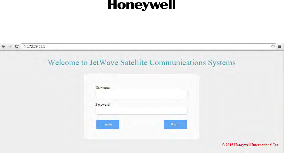
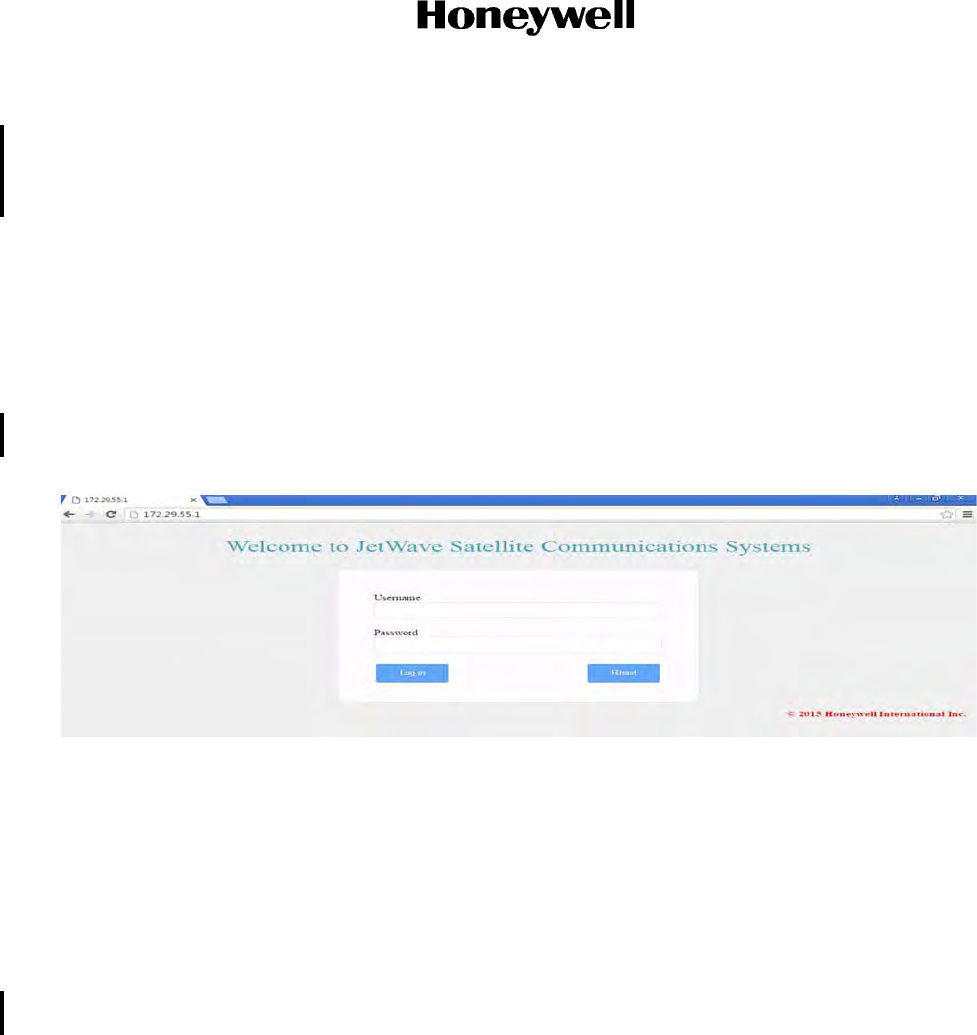
On any of the Internet browser (Internet Explorer 8 compatible), enter 172.29.55.1 in the address
bar. Login page will be presented as the root page, allowing entry of the user name and password.
Figure 6-2 shows the login page.
Table 6-1. Modman LED Status Indications
Status LED Mode
Off No electrical power/electrical power is supplied but
prior to boot.
Flash green at a minimum of 10 seconds Modman initialization
On - green Modman in normal operation
On - red Modman in Fault Mode
Draft as of 31 May 2017
Page 6-6
3 Mar 2017
23-15-29
SYSTEM DESCRIPTION AND INSTALLATION MANUAL
JetWave™ System
© Honeywell International Inc. Do not copy without express permission of Honeywell.
Figure 6-2. AES GUI Login Page
(a) The GUI is configured to have the login accounts that follow:
• User interface with Username: “User” and Password: empty (no) password
• Maintenance interface with Username: “Maintenance” and Password: “Earthbound”.
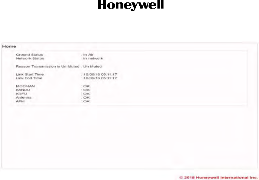
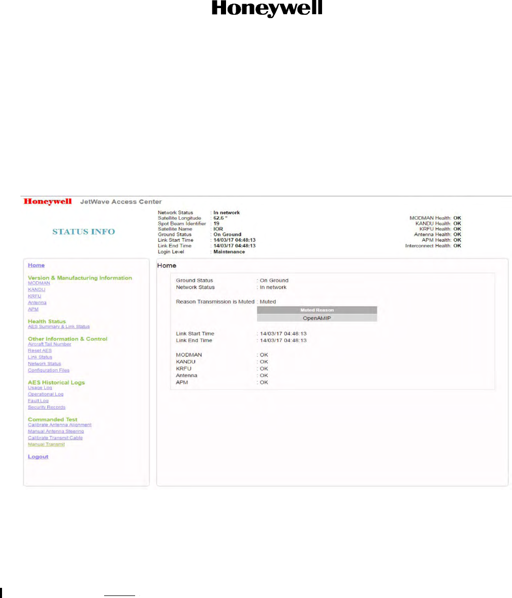
On successful login, the AES Home page screen is shown. Refer to Figure 6-3.
The information supplied on the AES Home page is as follows:
• Network status
• Ground status
• Mute Reason
• Link start and end time
• Heath status of the system LRUs.
The GUI AES Home page screen, as shown in Figure 6-3, lets the operator navigate to all
applicable options depending on the access level.
Draft as of 31 May 2017
Page 6-7
3 Mar 2017
23-15-29
SYSTEM DESCRIPTION AND INSTALLATION MANUAL
JetWave™ System
© Honeywell International Inc. Do not copy without express permission of Honeywell.
Figure 6-3. AES Home and Status Info Page
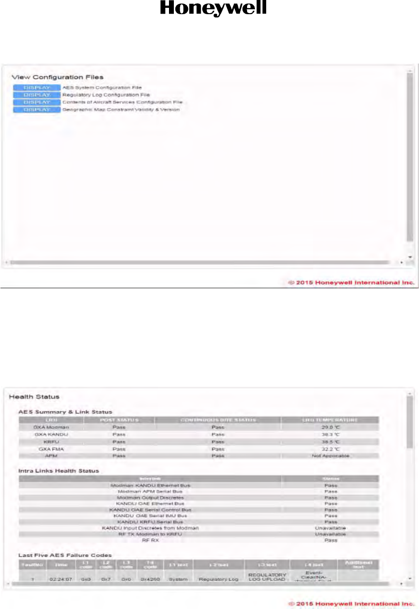
View and verify the AES configuration data, navigate to the "Configuration Files" information pages
under the other information and control menu.
The typical configuration file information page is shown in Figure 6-4. To view and make sure that
the AES configuration settings are current, click the AES configuration file to display.
The configuration data should be verified by going to the APM page in the Version and
Manufacturing Information menu and verifying the part numbers for the APM configuration
data
Draft as of 31 May 2017
Page 6-8
3 Mar 2017
23-15-29
SYSTEM DESCRIPTION AND INSTALLATION MANUAL
JetWave™ System
© Honeywell International Inc. Do not copy without express permission of Honeywell.
Figure 6-4. View Configuration Files Page
To view the health status of the JetWave™ system, navigate to the “AES Summary and Link Status”
under the Health Statuses menu on the left.
This will allow you to view and make sure of the health status of the JetWave™ system.
The AES summary and interlink status are shown in Figure 6-5.
Figure 6-5. Health Statuses (excerpt), AES Summary and Link Statuses
Draft as of 31 May 2017
Page 6-9
3 Mar 2017
23-15-29
SYSTEM DESCRIPTION AND INSTALLATION MANUAL
JetWave™ System
© Honeywell International Inc. Do not copy without express permission of Honeywell.
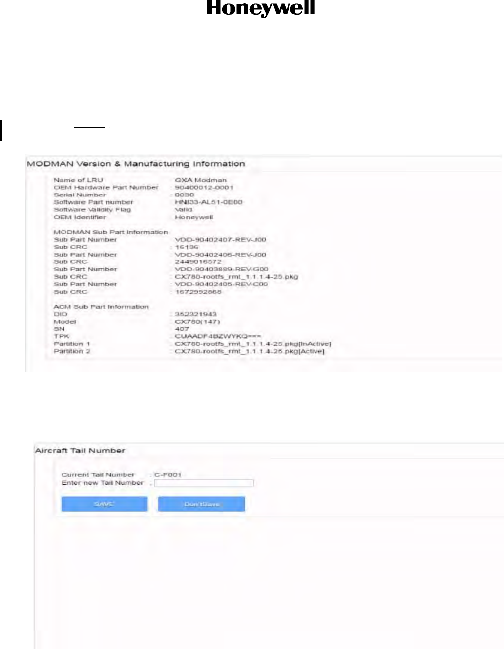
To see the AES LRUs hardware and software version and part number, navigate to the Version and
Manufacturing Information menu. Figure 6-6 shows the typical Modman Version and Manufacturing
Information page.
Make sure the version and manufacturing information are current for all the LRUs.
NOTE: Follow appropriate Jetwave Service Bulletin reference to validate the SW currently installed
on the Jetwave system.
Figure 6-6. AES Modman and Manufacturing Information Page
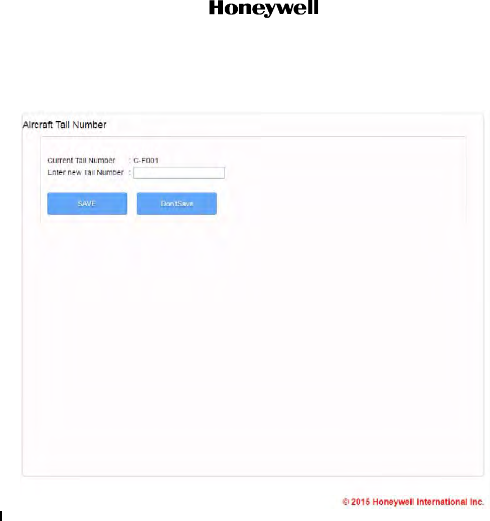
Update the aircraft tail number, navigate to the “Aircraft Tail Number” page under the other
information and control menu. The aircraft tail number page is shown in Figure 6-7.
Figure 6-7. Aircraft Tail Number Page
Draft as of 31 May 2017
Page 6-10
3 Mar 2017
23-15-29
SYSTEM DESCRIPTION AND INSTALLATION MANUAL
JetWave™ System
© Honeywell International Inc. Do not copy without express permission of Honeywell.
C. Discrete Input Testing
(1) If wired, activate the Modman Reset by toggling Modman reset switch on the JetWave™ AES
control panel.
(2) If the Modman Reset is not wired, then reset the system from the GUI.
(3) Monitor the Modman ”power” and “status” LEDs flash continuously.
(4) Toggle the Modman Reset switch on the Satcom test panel to the open/non-grounded
position.
(5) Monitor the “status” LED on the front of the Modman, progresses from red color to steady
state green as seen during initial power-on.
(6) Check for the Aircraft Tail number page and make sure that the aircraft tail number page is
updated with the aircraft Tail number.
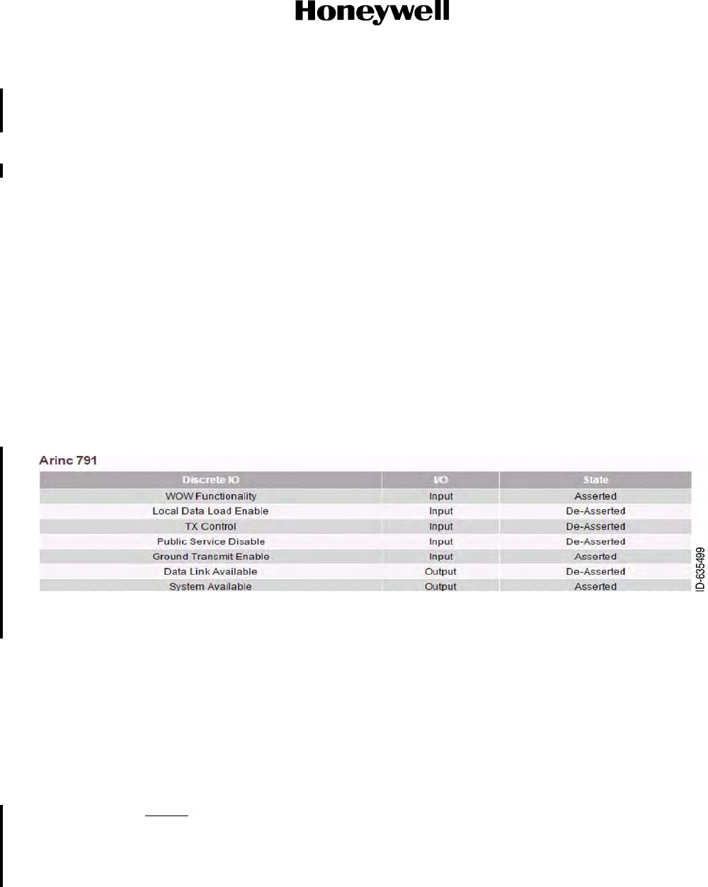
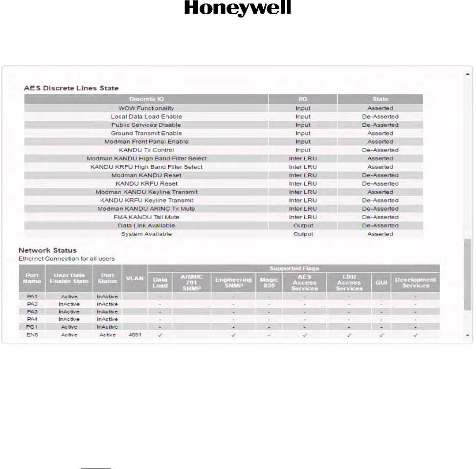
Navigate to the AES Summary and Link Status page and scroll down to see the ARINC 791
Discrete input and output state of the JetWave™ system. Refer to Figure 6-8.
For illustration, the figure that follows shows the AES discrete signal state. Use the wired aircraft
interfaces to toggle and see if the applicable discrete are asserted or de-asserted.
Figure 6-8. Discrete I/O State
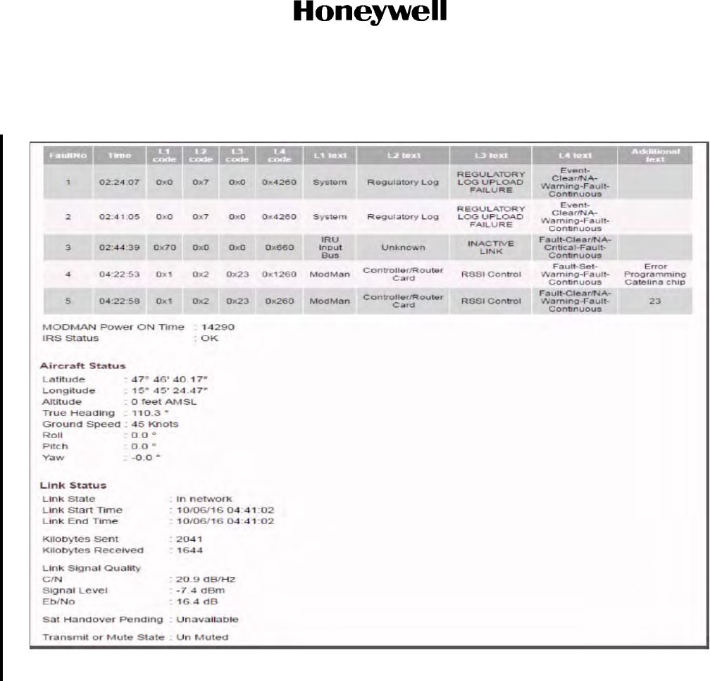
D. ARINC 429 Input Interface Testing
For the operation of the JetWaveTM system, the aircraft must have a functional IRS providing
ARINC 429 labels to the KANDU. Functional IRS is interfaced with the KANDU through Receive
only ARINC 429 interface through which the required ARINC 429 labels as defined in the APM
configuration file are made available.
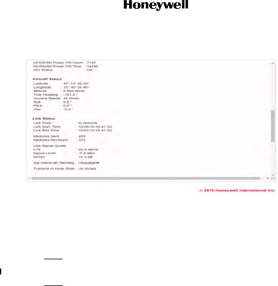
Navigate to the Link Status page and scroll down to see the aircraft status. Refer to Figure 6-9.
NOTE: GUI displays roll, pitch, and yaw information in the Aircraft Summary and Link status
page. The aircraft yaw information is calculated from True Heading and True Track
ARINC 429 labels from the aircraft. If True Track label is not configured, yaw value in
the GUI page will indicate as “Unavailable”. There will be no other effects if True
Track is not configured, other than that GUI status.
This page will be updated with current latitude and longitude position of the aircraft.
Draft as of 31 May 2017
Page 6-11
3 Mar 2017
23-15-29
SYSTEM DESCRIPTION AND INSTALLATION MANUAL
JetWave™ System
© Honeywell International Inc. Do not copy without express permission of Honeywell.
Once the JetWave™ system starts receiving the valid navigational input from aircraft IRS system,
make sure that the values are correct as compared to the aircraft navigational system outputs.
Figure 6-9. Aircraft Statuses
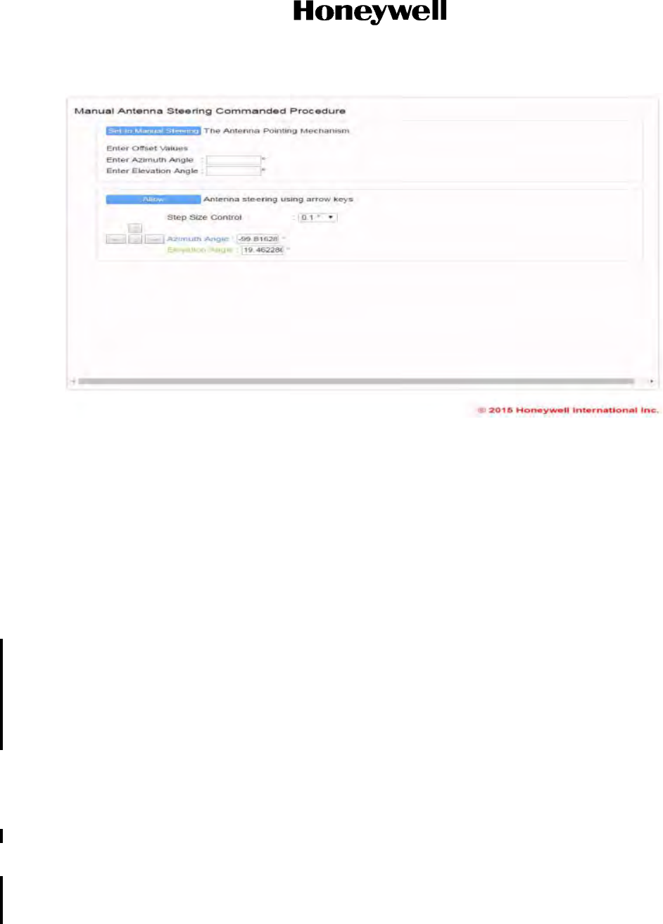
E. Manual Steering of the Antenna
To do a commanded test to manually steer the antenna, navigate to "Manual Antenna Steering"
under the commanded test menu. Monitor the antenna movement in accordance with the
commanded test fed through the GUI tool. Refer to Figure 6-10.
NOTE: In order to see the antenna movement, the radome can be removed. If it is an OAE-TMA,
Honeywell recommends manually steering the TMA through the GUI to a safe antenna
orientation position before removal. Consult aircraft specific SDIM for detailed instructions.
NOTE: New Radomes should be checked for any possible interference with normal Antenna
movement prior to activation. This can be accomplished many ways using manually
steering the Antenna with the Radome/Tail Cap lightly attached to structure. Placing
masking tape along critical paths inside the Radome and looking for breaks in the tape after
test and removal is one method of detecting interference.
Draft as of 31 May 2017
Page 6-12
3 Mar 2017
23-15-29
SYSTEM DESCRIPTION AND INSTALLATION MANUAL
JetWave™ System
© Honeywell International Inc. Do not copy without express permission of Honeywell.
Figure 6-10. Manual Antenna Steering
F. System Available (Cockpit Control Panel) Output
Once the JetWave™ system is powered up, monitor the “System Available” status discrete. Make
sure that the discrete state agrees with the discrete output in the GUI. Refer to Figure 6-11.
6.4 Cable Calibration
The Modman will not transmit until it has been calibrated, with the transmit cable calibration. After the AES
is physically installed and connected, the Modman will automatically initiate cable calibration during
start-up.
Cable calibration initiates automatically during the initial system commissioning process or after Modman
or KRFU replacement. Cable calibration must be initiated using a GUI commanded test after Tx IF cable
manipulation, connector re-seating and cable replacement.
The transmit cable calibration calibrates the terminal to allow accurate control of transmitter power, taking
into account IF output loss, cable loss, and KRFU (BUC) performance. During calibration, the power amp
of the BUC is disabled.
When calibration is completed successfully, the ACM proceeds to its configured mode of operation as if
it had been restarted. When commissioning is not completed successfully, either due to an error condition
or a user cancellation, the ACM enters an inactive state.
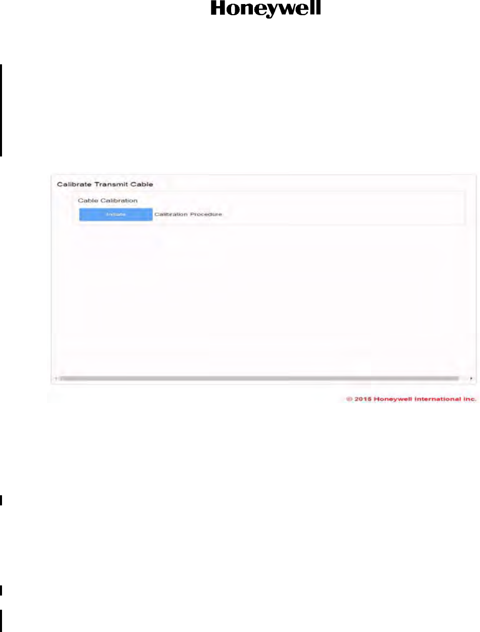
Cable Calibration is available through the GUI Commanded Test - Calibrate Transmit Cable. The Cable
Calibration procedure only takes up to 15 minutes to perform.
To maintain a fully optimized Jetwave system, it is recommended to perform a single cable calibration in
the 20 year service life, at around 8,000 to 12,000 hours of operation. This optimization will minimize
minor effects of device aging in the transmit chain, and can be performed conveniently using the GUI to
Draft as of 31 May 2017
Page 6-13
3 Mar 2017
23-15-29
SYSTEM DESCRIPTION AND INSTALLATION MANUAL
JetWave™ System
© Honeywell International Inc. Do not copy without express permission of Honeywell.
initiate the "Calibrate Transmit Cable" commanded test. The recommendation is not mandatory and
Jetwave will continue to operate at a high level of performance over the service life.
To maintain a fully optimized Jetwave system, it is recommended to perform a single cable calibration in
the 20 year service life, at around 8,000 to 12,000 hours of operation. This optimization will minimize
minor effects of device aging in the transmit chain, and may be performed conveniently using the GUI to
initiate the "Calibrate Transmit Cable" commanded test. The recommendation is not mandatory and
Jetwave will continue to operate at a high level of performance over the service life.
Figure 6-11. Calibrate Transmit Cable Status Page
6.5 TMA and FMA Antenna Alignment Procedure
A. Antenna Assembly Orientation
For the JetWave™ system to point to the servicing satellite correctly, it is important to align the
antenna assembly after installation or replacement. The TMA/FMA assembly has a built in IMU and
its orientation must be aligned with respect to the principal axes of the aircraft which is determined
through aircraft IRS.
(1) To do the automatic antenna alignment calibration, aircraft should have a functional IRS,
interfaced with the KANDU through A429 interface, and should have the required ARINC 429
labels as defined in the APM configuration file.
(2) During the physical installation, the IMU principal axes of the TMA/FMA must be aligned with
those of the aircraft within ± 1° on the pitch, roll, and yaw axis. The installation offsets, are
then calculated by the KANDU automatically from data received from the aircraft Inertial
Navigational System, the TMA/FMA IMU assembly and the satellite signal.
Draft as of 31 May 2017
Page 6-14
3 Mar 2017
23-15-29
SYSTEM DESCRIPTION AND INSTALLATION MANUAL
JetWave™ System
© Honeywell International Inc. Do not copy without express permission of Honeywell.
(3) It is required to do the automatic antenna alignment calibration with the Radome installed.
The antenna alignment process can be initiated through the GUI interface. The JetWave™
system GUI service is supported on AV1 10/100 Base T Ethernet interfaces (AV1 being
default configuration, ports may vary depending on specific APM configuration).
(4) Automatic Antenna Alignment
The antenna alignment should be performed only after completion of system power up. The
health status of each LRU should be checked on the GUI, and there should be no display of
system muting. Only then should the Initiate button be pressed on the Antenna Alignment
GUI page. The JetWave™ system GUI service is supported on AV1 and AG1 10/100 Base T
Ethernet interfaces.
(5) On any Internet browser (Internet Explorer 8 compatible), enter 172.29.55.1 in the address
bar. The Login page appears. Figure 6-12 shows the Login page.
Figure 6-12. GUI Login Page
(6) Enter the username and password below to access the maintenance interface.
• Username: "Maintenance" and Password: "Earthbound".
B. Positioning of Aircraft for Antenna Alignment
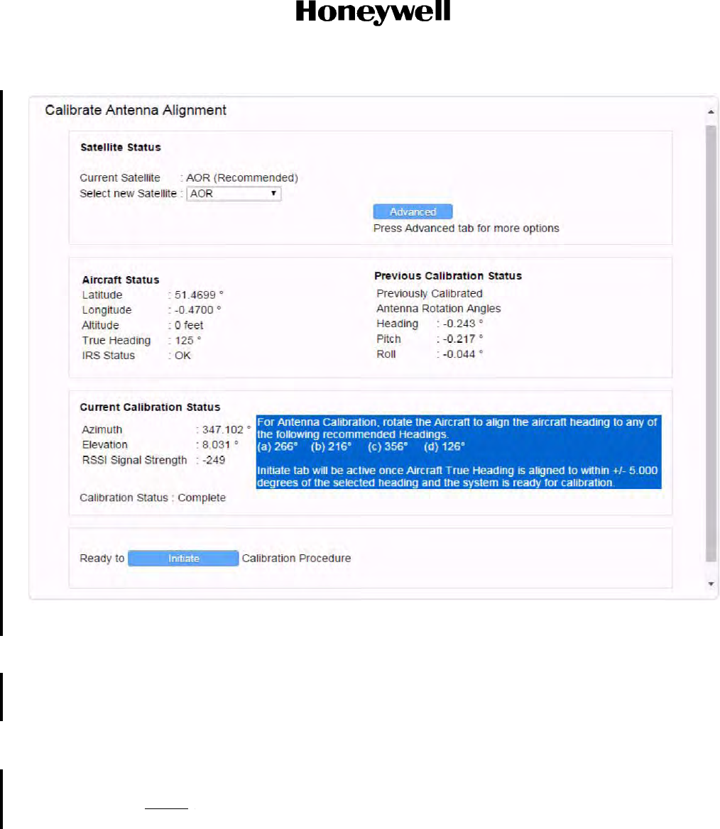
(1) On the GUI Calibrate Antenna Alignment page, as shown in Figure 6-13, the current location
of aircraft in terms of latitude and longitude is indicated along with the selection of the
servicing Geo stationary satellite used for the antenna alignment.
Draft as of 31 May 2017
Page 6-15
3 Mar 2017
23-15-29
SYSTEM DESCRIPTION AND INSTALLATION MANUAL
JetWave™ System
© Honeywell International Inc. Do not copy without express permission of Honeywell.
Figure 6-13. GUI Calibrate Antenna Alignment Page
(2) For the automatic antenna alignment calibration, it is recommended to tow and put the
aircraft in an open area away from aircraft hangars such that there is clear visibility to the
open sky with the true heading (not magnetic heading) of the aircraft pointed in one of four
recommended aircraft true heading values displayed on the GUI antenna calibration page.
(3) The automatic antenna alignment calibration can be carried out at up to four different aircraft
headings. Out of the available headings, it is required to do only one automatic alignment
calibration while the aircraft true heading is toward one of the preferred directions.
NOTE: The values displayed in Figure 6-14 will change depending on the location and
attitude of the aircraft.
Draft as of 31 May 2017

Page 6-16
3 Mar 2017
23-15-29
SYSTEM DESCRIPTION AND INSTALLATION MANUAL
JetWave™ System
© Honeywell International Inc. Do not copy without express permission of Honeywell.
(4) The recommended values are dependent on the radome and these values are calculated by
the KANDU based on the input from the aircraft IRS and the selected satellite coordinates
and the APM configuration data. The Auto Alignment application automatically presents the
four true headings to the operator when a target satellite is selected from the “recommended”
target which is also location dependent. There is a recommended tolerance range for these
headings which is dependent on the radome and configured in the APM configuration
data.The chosen recommended true headings are used so that the radome has consistent
performance (i.e. no large changes in curvature) over the area being used during alignment.
NOTE: It is advised not to do the automatic antenna alignment during rains with heavily
clouded sky.
(a) The antenna alignment should be performed only after completion of system power up.
The health status of each LRU should be checked on the GUI, and there should be no
display of system muting due to Initialization. Only then should the Initiate button be
pressed on the Antenna Alignment GUI page.
(b) The JetWave™ system uses the following input parameters during the antenna
alignment procedure:
• Aircraft IRS data
• OAE IMU data
• RSSI as reported from the Modman.
(c) The GUI page indicates the status of the aircraft. In order to proceed with the antenna
calibration process, all LRUs of the JetWave™ system need to be powered up with
aircraft IRS system functioning and providing valid inputs. The GUI page indicates the
IRS status.
(d) Once the aircraft is aligned to within the tolerance range of any of the recommended
aircraft heading, the grayed out on the “Initiate” button will be changed, indicating the
system readiness to commence the antenna alignment process.
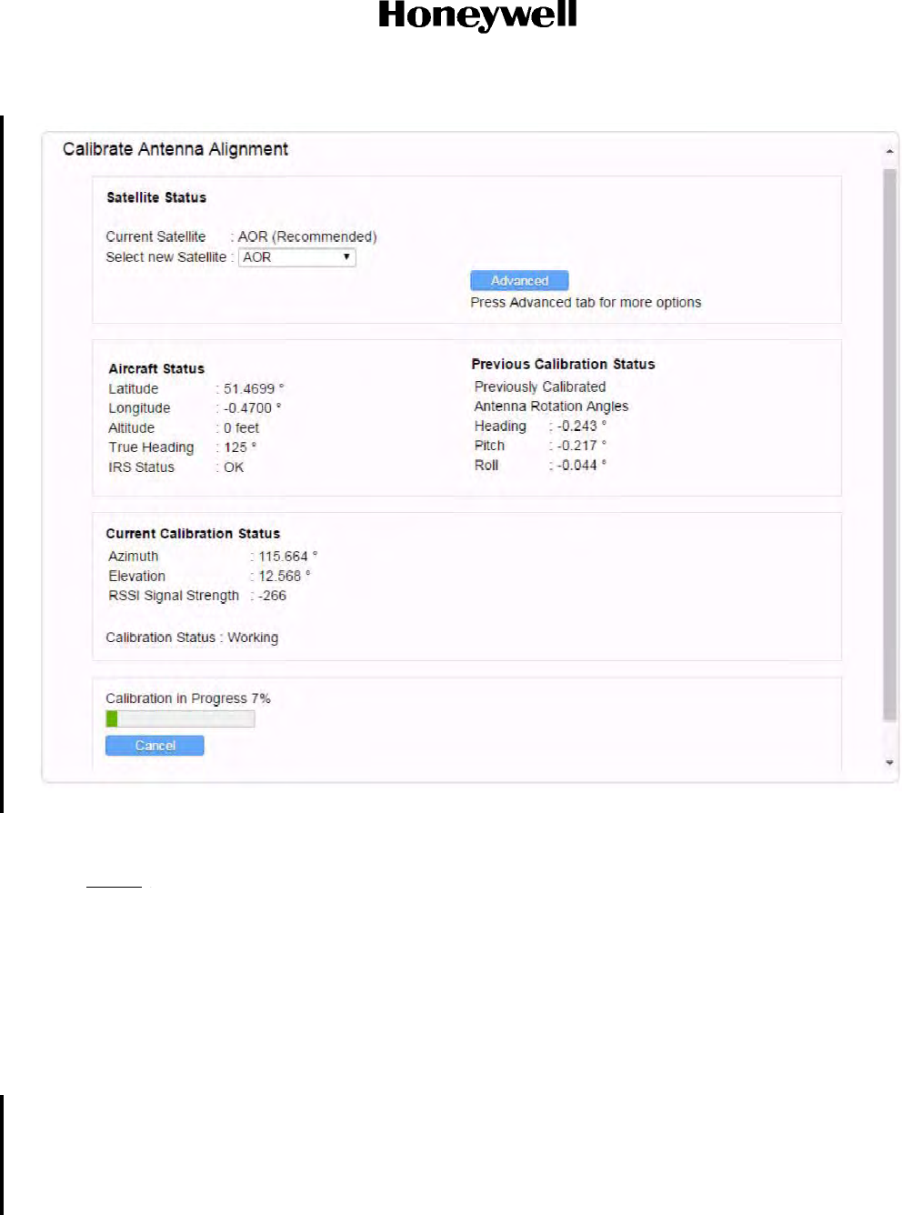
(e) The GUI Antenna Alignment Calibration progress status bar is shown in Figure 6-14.
(f) On successful completion of the antenna calibration, the status changes to “Aligned”.
NOTE: If for some reason the Calibration procedure fails, the operator will be given the
opportunity to repeat the procedure. This may require several attempts to
finalize and confirm the offsets.
Draft as of 31 May 2017
Page 6-17
3 Mar 2017
23-15-29
SYSTEM DESCRIPTION AND INSTALLATION MANUAL
JetWave™ System
© Honeywell International Inc. Do not copy without express permission of Honeywell.
Figure 6-14. GUI Antenna Alignment Calibration Page Extract
6.6 On-ground Testing and Commissioning
NOTE: There are restrictions to testing the JetWave™ system for the commissioning process.
Each country has its own restrictions to on-ground testing and transmission. Verify regulations
before testing the system. Particular attention must be observed the first time the system is turned
on and able to transmit. At this point the system will download a map detailing the areas where
transmission is and is not allowed. This map will take effect on the next power-up.
A. Testing and Commissioning Process with Restrictions
(1) The JetWave™ system under normal operating conditions mutes transmit and also disables
the modem when the Air/Ground status in "On Ground".
(2) The Air/Ground status will be set to "Air" when one of the conditions that follow are met
(otherwise the Air/Ground status will be set to "On Ground"):
• IF AES Configuration System KANDU Ground Speed is being received from the
KANDU (Refer to SRS1525), and it has been received with non NULL valve, and is
indicating a ground speed of greater than 50 knots, or
Draft as of 31 May 2017

Page 6-18
3 Mar 2017
23-15-29
SYSTEM DESCRIPTION AND INSTALLATION MANUAL
JetWave™ System
© Honeywell International Inc. Do not copy without express permission of Honeywell.
• If AES Configuration System wow is configured to be connected and it is indicating it
is in the air.
(3) Ground transmission can be enabled by asserting the ground transmit enable discrete of the
JetWave™ system.
(a) The ground operation depends on location and country of aircraft registration.
(b) The reason for restrictions on transmission from the current aircraft location can be
accessed through the GUI Home page under text display “Reasons for Transmission
Mute”.
(4) For the testing and commissioning process, the aircraft must be positioned so as to have a
clear line of sight to the satellite.
(5) To control the transmission of the terminal within certain locations and at different heights, the
terminal stores and uses a geographical map. The map indicates regions around the globe
where the terminal may legally transmit. The map is provided by Inmarsat and requested by
the terminal when it first enters the network. The terminal will retrieve the map file from the
Inmarsat server using the FTP protocol over the management VLAN. Make sure that this
ground test procedure is being performed in a location that permits operation on the ground
for the terminal's configured geographic map.
B. Data Link Available (Control Panel) Output
Once the network connectivity is achieved, the “Datalink Available” discrete output on the ARINC
791 page will be asserted.
To see the “Datalink Available” discrete output, navigate to the AES Summary and Link Status page
and scroll down to see the ARINC 791 page and make sure the discrete output status is asserted,
Refer to the Discrete I/O state page Figure 6-8.
Make sure the “Datalink Available” status is indicated in the control panel.
6.7 Final System Checkout
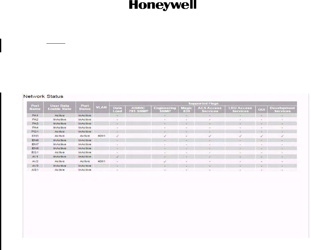
A. Network Status
Navigate to the AES Summary and Link Status page and scroll down to see the Network status of
the JetWave™ system.
An example of an AES network status is shown in Figure 6-15.
Make sure that the network connectivity is in accordance with the aircraft configuration plan.
With the use of another laptop, make sure that there is network connectivity on each active port
once the data link available output is available.
Begin a two way (Rx and Tx) video conference call with a tool such as Microsoft Lync or Skype.
Make sure that there is availability of the uninterrupted data connectivity. Monitor the Kilobytes sent
and received fields on the home page.
While the JetWave™ system is up and connectivity to the internet is established, move the aircraft
around in a circular 360 degree pattern (no faster than 3° per second).
Draft as of 31 May 2017
Page 6-19
3 Mar 2017
23-15-29
SYSTEM DESCRIPTION AND INSTALLATION MANUAL
JetWave™ System
© Honeywell International Inc. Do not copy without express permission of Honeywell.
NOTE: Based on the geographical location, surrounding obstructions, etc., the 360 degree
connectivity access can be limited.
Verify that the connectivity remains available through the 360-degree turn by monitoring the
datalink status discrete.
Connect to each of the configured Ethernet ports to make sure there is data connectivity.
Figure 6-15. Network Statuses
B. EMC Interference to Other Systems
(1) Power up the system and let it acquire to the network.
(2) Begin a two way (Rx and Tx) video conference call with a tool such as Microsoft Lync or
Skype.
(3) Test the functioning of other systems with antennas installed adjacent to the FMA or TMA and
observe for any mutual interference.
(4) Monitor the link signal quality C/N and Eb/No parameters. These parameters are found under
Aircraft Statuses as part of the AES Summary and Link Status page. Refer to Figure 6-9.
(5) In case of any RF interference, there will be significant variation of the C/N and Eb/No
parameters.
Draft as of 31 May 2017

Page 6-20
3 Mar 2017
23-15-29
SYSTEM DESCRIPTION AND INSTALLATION MANUAL
JetWave™ System
© Honeywell International Inc. Do not copy without express permission of Honeywell.
Blank Page
Draft as of 31 May 2017
Page 7-1
3 Mar 2017
23-15-29
SYSTEM DESCRIPTION AND INSTALLATION MANUAL
JetWave™ System
© Honeywell International Inc. Do not copy without express permission of Honeywell.
SECTION 7
TROUBLESHOOTING
7.1 Post-installation Troubleshooting
This section supplies troubleshooting procedures for the JetWave™ system. Airline maintenance
engineers can troubleshoot the JetWave™ system on the ground, with the health status information and
Fault Details and Isolation assistance displayed on the AES GUI.
Only qualified avionics personnel who are knowledgeable in the technical and safety issues related to the
troubleshooting of aircraft communications equipment should do the troubleshooting.
7.2 Accessing the Maintenance Interface
(1) For maintenance activities, the JetWave™ system can be accessed through a GUI.
(2) The GUI service is supported on AV1 and AG1 10/100 Base T Ethernet interface.
NOTE: Once the configuration file is loaded, the ports where the GUI are available can be
different.
(3) The Modman static IP assigned is 172.29.55.1 and the port number for the AES GUI service
is port 80.
NOTE: This port is configured by the AES configuration user port services support
information.
(4) On any of the Internet browsers (Internet Explorer 8 compatible), open the link "index.html".
(5) Login page will be shown as the root page, for you to enter the user name and password.
Refer to Figure 7-1 for the screen-shot of the login page.
Figure 7-1. AES GUI Login Page
Draft as of 31 May 2017
Page 7-2
3 Mar 2017
23-15-29
SYSTEM DESCRIPTION AND INSTALLATION MANUAL
JetWave™ System
© Honeywell International Inc. Do not copy without express permission of Honeywell.
(6) Use the applicable login account with well defined password in the login page for accessing
the interface level required. The login for the maintenance interface and user interface is as
follows:
• Access maintenance interface with Username: “Maintenance” and Password:
“Earthbound”.
• Access the user interface with Username: “User” and no password.
(7) User may press Log out button to log out. Upon logging off, log in page will be presented by
default. Figure 7-2 shows the log out page.
Figure 7-2. JetWave™ Logout Page
A. Checking Status Information
(1) The health status of the JetWave™ system can be monitored by selecting AES Summary and
Link Status under the Health Status pane menu. Figure 7-3 shows the GUI page listing the
health status of JetWave™ system LRUs.
NOTE: The Health Status page does not automaticaly refresh.
(a) In the health status page, the GUI lists the last five AES failure codes.
(b) The JetWave™ system will enter into critical fault mode when a critical LRU fault is
encountered or the AES Configuration data is missing or invalid.
(c) The JetWave™ system will be back to normal operation mode only when all the LRU
critical faults are removed, receiving valid navigation information, and a valid AES
Draft as of 31 May 2017
Page 7-3
3 Mar 2017
23-15-29
SYSTEM DESCRIPTION AND INSTALLATION MANUAL
JetWave™ System
© Honeywell International Inc. Do not copy without express permission of Honeywell.
configuration data is supplied. Figure 7-3 shows the AES Summary and Link Status
page.
Figure 7-3. JetWave™ Summary and Link Status (Sheet 1 of 2)
Draft as of 31 May 2017
Page 7-4
3 Mar 2017
23-15-29
SYSTEM DESCRIPTION AND INSTALLATION MANUAL
JetWave™ System
© Honeywell International Inc. Do not copy without express permission of Honeywell.
Figure 7-3. JetWave™ Summary and Link Status (Sheet 2 of 2)
(2) The JetWave™ system status can be viewed through the GUI. Refer to AES system status
verification section on page 6-3 for description.SUmmary and link status
B. Downloading LRU Logs
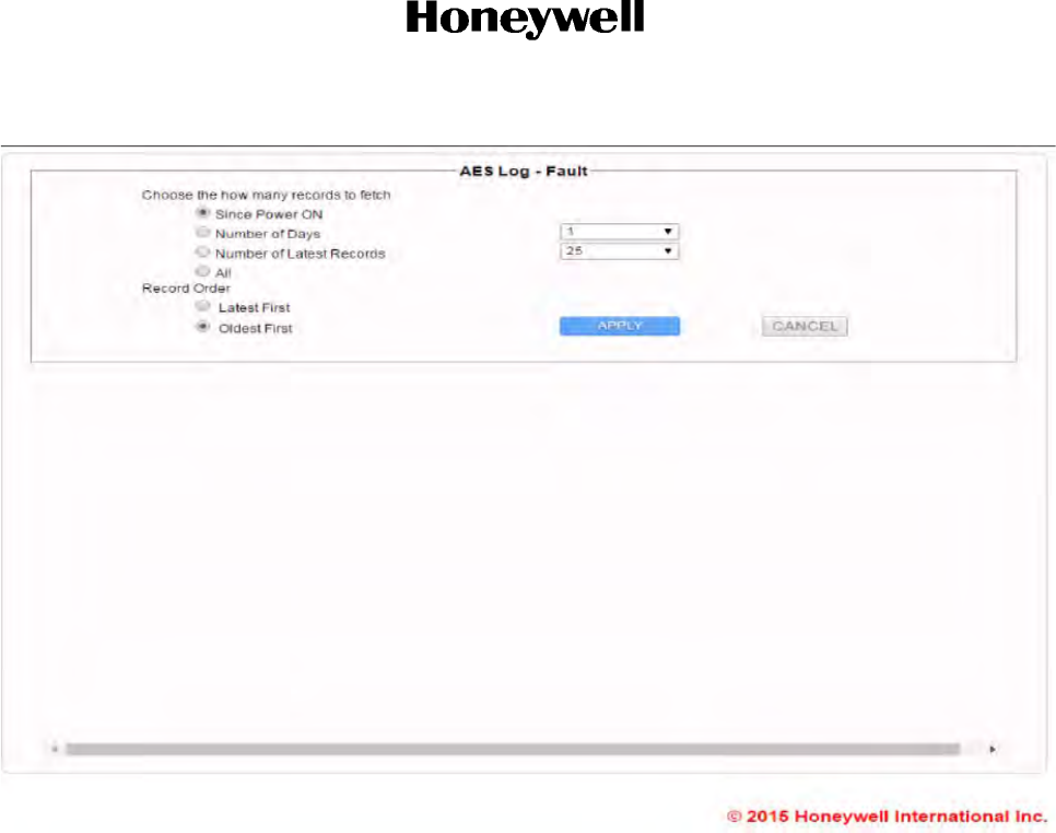
(1) To view the historical fault logs, under the AES historical logs pane, select the "Fault Log". A
screenshot of fault log page is shown in Figure 7-4.
NOTE: The JetWave™ System Usage log and the Operational log can be downloaded
through GUI with User access level. For downloading the JetWave™ System Fault
log and the Security records, the system must be accessed through the Maintenance
access level on the GUI.
(2) The log files can be viewed a number of ways. You can choose how many records as follows:
• Since power on
• Number of days and select actual number of days from the dropdown (not reconmended)
• Number of latest records and select the number of records form the dropdown
(3) Select the record order by clicking on latest first or oldest first.
(4) Select the Apply button.
Draft as of 31 May 2017
Page 7-5
3 Mar 2017
23-15-29
SYSTEM DESCRIPTION AND INSTALLATION MANUAL
JetWave™ System
© Honeywell International Inc. Do not copy without express permission of Honeywell.
Figure 7-4. JetWave™ Fault Log Download Configuration Page
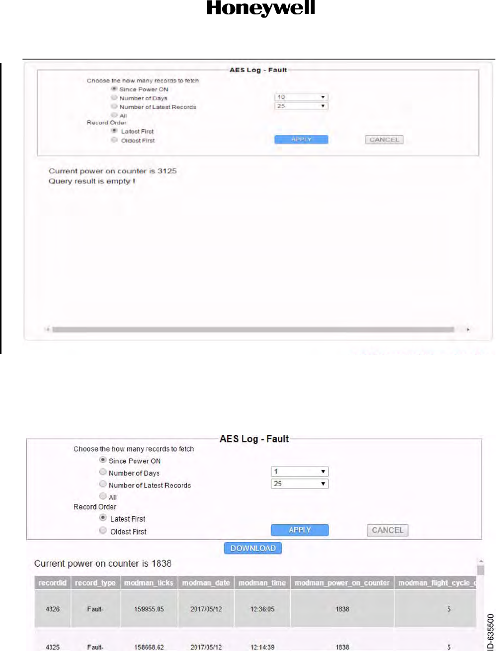
(5) The fault log contains the details that follow:
• LRU POST and BITE fault codes
• Watch dog reset events
• Software exception events
• LRU Recorded Temperature, if available
• LRU Recorded Time, if available
• LRU Antenna pointing information, if applicable
•Fault count.
Refer to Figure 7-5 for an example of a viewable fault log.
Draft as of 31 May 2017
Page 7-6
3 Mar 2017
23-15-29
SYSTEM DESCRIPTION AND INSTALLATION MANUAL
JetWave™ System
© Honeywell International Inc. Do not copy without express permission of Honeywell.
Figure 7-5. JetWave™ Fault Log Data
(6) To download the fault log data for analysis and trouble shooting, press the “Download”
button. The window as shown in Figure 7-6 will come into view. Save to the computer to open
and view the fault log.
Figure 7-6. JetWave™ Fault Log Download Page
Draft as of 31 May 2017

Page 7-7
3 Mar 2017
23-15-29
SYSTEM DESCRIPTION AND INSTALLATION MANUAL
JetWave™ System
© Honeywell International Inc. Do not copy without express permission of Honeywell.
C. System Data Load Failure
(1) Make sure that the system is configured for ground operation.
(2) Make sure that the local data load enable switch is closed.
(3) Make sure that the ARINC 615A data loader is connected to the correct port:
NOTE: Port AV1 is by default the Modman Maintenance Port, but this may have been
modified by the APM configuration loaded.
D. System Reset
The JetWave™ system can be reset with any of the methods that follow:
• GUI
• Through the SNMP
• By grounding the Modman Reset Pin (MP10C).
NOTE: The maintenance technician can attempt to cycle power to the Modman in case the system fails
to respond to the reset. If the problem persists, the respective AES sub assembly needs to be
replaced. The operator's JetWave Customer Support can be contacted for further support.
E. Electrical and Mechanical Inspection and Check
Periodic inspections of the mechanical and electrical interfaces of the JetWave™ AES OAE
assembly and LRUs to the aircraft should be completed as defined by the governing airworthiness
body (such as Transport Canada, the FAA, or the JAA) Instructions for Continued Airworthiness for
the installation.
For the general guidelines, refer to Visual Inspection and Check and Scheduled Maintenance and
Inspections sections.
F. Visual Inspection and Check
Do the procedures that follow to examine the JetWave™ AES OAE assembly and LRUs after
installation of the unit onto the aircraft. Follow all approved safety standards and practices during
the inspection.
WARNING: FAILURE TO DISCONNECT CIRCUIT BREAKERS CAN LEAD TO INJURY TO THE
OPERATOR AND DAMAGE TO THE EQUIPMENT.
(1) Disconnect all circuit breakers to the JetWave™ AES OAE assembly, LRUs and associated
systems.
(2) Visually examine the FMA or TMA radome for any damage or defects. Please refer to the
radome supplier’s Structural Repair Manual (SRM) for the specific radome inspection and
damage repair instructions.
NOTE: Saint Gobain SRM-100 is applicable to all radomes. FMA radome, PN
SCD-90401395-01, is covered specifically by Saint Gobain SRM-5249 structural
repair manual.
Draft as of 31 May 2017
Page 7-8
3 Mar 2017
23-15-29
SYSTEM DESCRIPTION AND INSTALLATION MANUAL
JetWave™ System
© Honeywell International Inc. Do not copy without express permission of Honeywell.
G. JetWave™ System Fault Codes
(1) BITE Philosophy
(a) Description
1The JetWave™ AES consists of the Modman, KANDU, KRFU, TMA or FMA LRUs,
plus the APM.
2The APM is a simple memory device with no software and performs no BITE by
itself. Any BITE required for the APM is performed by the Modman. The APM is not
shown in these diagrams.
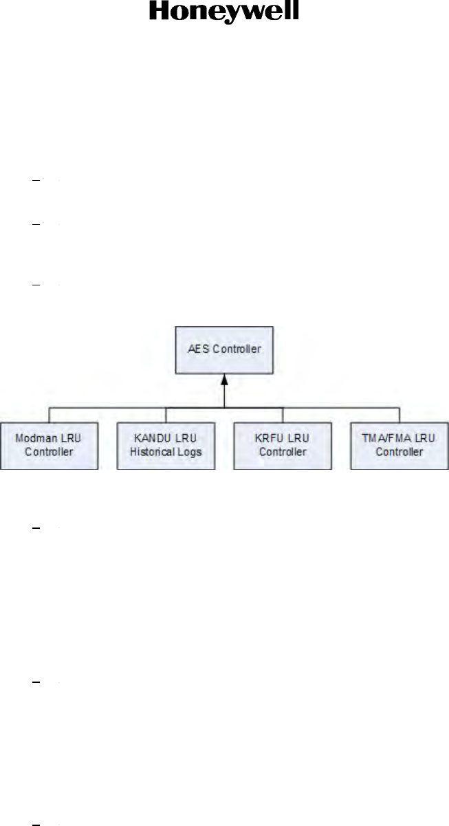
3The BITE system divides the responsibility for BITE and historical logs in a BITE
hierarchy as illustrated in Figure 7-7.
Figure 7-7. Bite Hierarchy
4In charge of the JetWave™ system is the AES controller. This controller is in charge
of the LRUs of the JetWave™ system, and it:
• Maintains the overall state of the AES system
• Controls the initialization and operation of the system
• Generates BITE events applicable to the system level
• Records BITE events reported by a LRU and itself in an AES historical log.
5Each LRU has a LRU controller that:
• Maintains the state of the LRU
• Generates BITE events applicable to the LRU
• Sends relevant BITE events to the AES controller (for the AES controller to
make a decision on overall AES state, and for it to record in its AES historical
log).
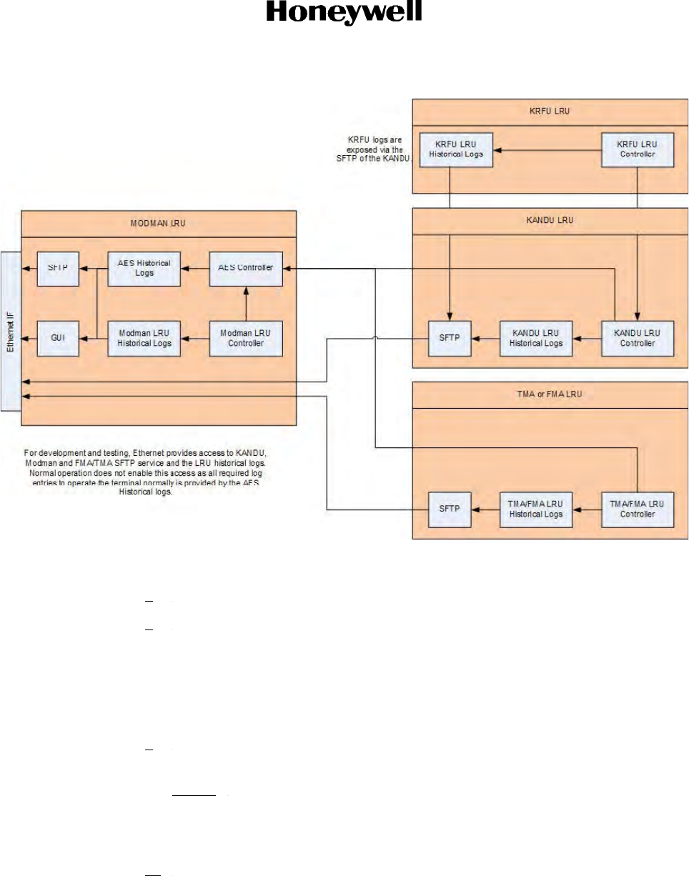
6The diagram that follows is a detailed description of how the AES controller, the
LRU controllers, the historical logs, and the means of access to those logs interact.
Refer to Figure 7-8.
Draft as of 31 May 2017
Page 7-9
3 Mar 2017
23-15-29
SYSTEM DESCRIPTION AND INSTALLATION MANUAL
JetWave™ System
© Honeywell International Inc. Do not copy without express permission of Honeywell.
Figure 7-8. AES and LRU Controller Interaction
7The AES Controller resides in the Modman LRU.
8Each LRU Controller monitors the LRU for BITE events. BITE events are classified
into two categories:
• Faults: These are BITE events which have a SET state (occurring) or CLEAR
state (fault has disappeared).
• Events: These are BITE events which occur but do not have a set or clear state.
9The LRU records the BITE event into a specific LRU log, dependent on the type of
fault or event.
NOTE: Not all BITE events indicate an error situation. BITE events are also used
for storing significant events in the historical logs, either on the LRU or in
the AES controller, or for informing the AES controller of important system
wide information.
10 BITE events are sent to the AES controller. The AES controller may react to an
event by changing the overall state of the AES system. Actions include disabling the
system, rebooting the system, etc.
Draft as of 31 May 2017

Page 7-10
3 Mar 2017
23-15-29
SYSTEM DESCRIPTION AND INSTALLATION MANUAL
JetWave™ System
© Honeywell International Inc. Do not copy without express permission of Honeywell.
11 The AES controller has a sub-part called the AES controller fault and event handler
which is in charge of responding to BITE events reported by the AES controller or
a LRU controller.
12 The AES controller has its own historical logs which allow it to record events about
the whole system.
13 Included on the diagram are the Secure File Transport Protocol (SFTP) services
and the GUI services which allow the users to access the AES and LRU historical
logs.
•AES controller logs are available from the Modman LRU GUI or SFTP
service, accessible through one of the Ethernet connections on the
Modman.
• Modman LRU logs are available from the Modman LRU SFTP service,
accessible through one of the Ethernet connections on the Modman.
• KANDU LRU Logs and KRFU LRU Logs are available from the KANDU LRU
SFTP service, accessible through one of the Ethernet connections on the
Modman.
• TMA/FMA LRU Logs are available from the TMA/FMA LRU SFTP service,
accessible through one of the Ethernet connections on the Modman.
14 The LRU and AES remember information about BITE events that have occurred, in
both non-volatile memory and volatile memory.
15 The historical logs are kept by the LRU and AES controller.
16 Each BITE event is described by an LRU code, encoded in three numbers (L1, L2
and L3) to uniquely identify the event.
17 Section 5 has more details on the format of this LRU code system.
18 The BITE events themselves have a description of the L1 thru L3 code and the
additional text to be used for that event.
19 Each BITE event is also associated with a reaction table which describes the
confirmation actions, and event actions, the LRU should take when this BITE event
occurs. For events that are reported to the AES controller, there is a reaction table
describing what the AES controller should do when the event is reported to it.
(a) Status Memory
1The AES Controller remembers the following information:
• The AES Controller maintains an overall mode of operational state, of
UNKNOWN (Default), DATA LOAD, CRITICAL FAULT, COMMANDED
MODE, OPERATIONAL MODE.
• The AES controller maintains an overall service state, of AVAILABLE
(default) or UNAVAILABLE. This service state, when set to UNAVAILABLE,
disables user service and transmission.
Draft as of 31 May 2017

Page 7-11
3 Mar 2017
23-15-29
SYSTEM DESCRIPTION AND INSTALLATION MANUAL
JetWave™ System
© Honeywell International Inc. Do not copy without express permission of Honeywell.
• For each unique L1 thru L3 code, maintained across reset/power down, it
records if the code has occurred (SET), cleared after occurring (CLEAR), or
never seen (NO_ERROR).
• For each unique L1 thru L3 code, maintained across reset/power down, it
records the number of occurrences and the time of the last occurrence.
• For every link in the system, it records the status: UNKNOWN (default after
power on), DISABLED, INACTIVE, NO_LAYER_1 (when applicable),
HIGH_PACKET_LOSS, ACTIVE (normal). It also records the time of the last
report, and the long term link status: NOFAULT, FAULT.
• For every ARINC 429 label the AES accepts on a per LRU basis, it records
the status: DISABLED, UNKNOWN (default after power on), ACTIVE,
SSMERROR, MISSING.
• For every input discrete the AES LRUs possesses, it records the status:
UNKNOWN (default after power on), ASSERTED, DEASSERTED.
• For every temperature sensor on every LRU the AES controller records its
status: NORMAL (default after power on), WARNING, CRITICAL.
• For the Modman, KRFU, KANDU, TMA, FMA the AES controller records it
overall hardware state: NORMAL (default after power on), WARNING,
FAILED.
• The AES controller maintains in memory the mute state of each LRU, and
the reason for mute. Default is “INITIALIZATION”.
2The LRUs remember the following information:
• For each unique L1 thru L3 code, maintained across reset/power down, it
records if the code has occurred (SET), cleared after occurring (CLEAR), or
never seen (NO_ERROR).
• For each unique L1-L3 code, maintained across reset/power down, it
records the number of occurrences and the time of the last occurrence.
• For every link the LRU has, it records the status: UNKNOWN (default after
power on), DISABLED, INACTIVE, NO_LAYER_1 (when applicable),
HIGH_PACKET_LOSS, ACTIVE (normal). It also records if the link is
causing a mute of the system.
• For every ARINC 429 label the LRU understands, it records the status:
DISABLED, UNKNOWN (default after power on), ACTIVE, SSMERROR,
MISSING. It also records if the label is causing a mute of the system.
• For every input discrete the LRU possesses, it records the status:
ASSERTED, DEASSERTED.
• The LRU maintains in memory the reason, if any, for muting.
Draft as of 31 May 2017

Page 7-12
3 Mar 2017
23-15-29
SYSTEM DESCRIPTION AND INSTALLATION MANUAL
JetWave™ System
© Honeywell International Inc. Do not copy without express permission of Honeywell.
(2) LRU Codes
BITE event information is encoded by the LRUs in three values. The values are named L1
thru L3:
• L1 denotes the LRU or interface (generated by an LRU on its behalf) which
is generating the event
• L2 denotes the Shop Replaceable Module within an LRU for a event relating
to an LRU, or for interfaces it denotes a particular part of the interface which
is generating the event.
• L3 further defines the unique event that occurred.
Each fault or event also has an additional text field which can carry additional information
helpful to understand the fault or event that happened.
The combination of L1 thru L3 alone uniquely identifies a BITE event in the system.
(3) L1 Codes
(a) The event L1 code uses two hexadecimal digits to identify a LRU or an interface within
an AES LRU, coded as follows:
Table 7-1. L1 Codes
Group L1 Code L1 Description
System 0x 00 System
The L1 code of 00 shall be used if the LRU is
unknown or if the error is applicable to a system level,
such as an invalid or unknown system configuration
error, or a system event not specific to an LRU.
AES 0x 01 Modman
0x 02 KRFU
0x 03 TMA
0x 04 FMA
0x 05 APM
0x 06 KANDU
Draft as of 31 May 2017

Page 7-13
3 Mar 2017
23-15-29
SYSTEM DESCRIPTION AND INSTALLATION MANUAL
JetWave™ System
© Honeywell International Inc. Do not copy without express permission of Honeywell.
Intra-system Interconnect 0x 20 Modman KANDU Ethernet bus
0x 21 Modman APM serial bus
0x 23 Modman input discretes from LRU
0x 24 Modman output discretes
0x 30 KANDU OAE Ethernet Bus
0x 31 KANDU OAE Serial Control Bus
0x 32 KANDU OAE serial IMU bus
0x 33 KANDU KRFU serial bus
0x 34 KANDU input discretes from OAE
0x 35 KANDU input discretes from Modman
0x 36 KANDU input discretes from KRFU
0x 41 KRFU input discretes from KANDU
0x B0 RF TX Modman to KRFU
0x B1 RF TX KRFU to OAE
0x B2 RF RX
Aircraft Interconnect 0x 70 IRU input bus
0x 71 Aircraft state input bus
0x 72 Modman aircraft discrete input
0x 73 KANDU aircraft discrete input
AISD Network 0x 80 AISD Network: Ethernet AG1
0x 81 AISD Network: Ethernet AV1
0x 82 AISD Network: Ethernet AV2
0x 83 AISD Network: Ethernet AV3
PIESD Network 0x 88 PIESD Network: Ethernet EG1
0x 89 PIESD Network: Ethernet EN5
0x 8A PIESD Network: Ethernet EN6
0x 8B PIESD Network: Ethernet EN7
0x 8C PIESD Network: Ethernet EN8
Table 7-1. L1 Codes (Continued)
Group L1 Code L1 Description
Draft as of 31 May 2017

Page 7-14
3 Mar 2017
23-15-29
SYSTEM DESCRIPTION AND INSTALLATION MANUAL
JetWave™ System
© Honeywell International Inc. Do not copy without express permission of Honeywell.
NOTE: All other codes not explicitly stated are spare.
(4) L2 Codes
(a) The event L2 code uses two hexadecimal digits to identify a shop-replaceable module
within an AES LRU, coded as follows:
PODD Network 0x 90 PODD Network: Ethernet PG1
0x 91 PODD Network: Ethernet PA1
0x 92 PODD Network: Ethernet PA2
0x 93 PODD Network: Ethernet PA3
0x 94 PODD Network: Ethernet PA4
Table 7-2. L2 Codes – Module Within an AES LRU
L1 L2 Code L2 Description
System (00) 0x 00 Unknown
0x 01 Mode
0x 02 AES menu access level
0x 03 Configuration
0x 04 AES SFTP
0x 05 SNMP engineering
0x 06 SNMP ARINC 791
0x 07 Regulatory logs
0x 08 Information events
Modman (01) 0x 00 Unknown
0x 01 ACM
0x 02 Controller/Router
0x 03 Power supply unit
0x 04 Backplane
0x FA Operational information
0x FB IP security
0x FC Reset
0x FD Software configuration
0x FE Software runtime
Table 7-1. L1 Codes (Continued)
Group L1 Code L1 Description
Draft as of 31 May 2017

Page 7-15
3 Mar 2017
23-15-29
SYSTEM DESCRIPTION AND INSTALLATION MANUAL
JetWave™ System
© Honeywell International Inc. Do not copy without express permission of Honeywell.
Modman (01) 0x FF Temperature
KRFU (02) 0x 00 Unknown
0x 01 Power supply unit
0x 02 Block up converter
0x 04 Power amplifier
0x 05 Monitor and control
0x 07 Fan
0x 08 Failed on start-up
0x 2A BDC
0x FA Operational information
0x FC Reset
0x FD Software configuration
0x FE Software runtime
0x FF Temperature
TMA (03)
FMA (04) 0x 00 Unknown or not applicable
0x 02 Inertial measurement unit
0x 03 Low noise amplifier
0x 04 Motors and sensors
0x 05 Position control unit
0x 06 Power supply unit
0x 0B MDU
0x 0C R2D
0x FA Operational information
0x FB IP security (FMA only)
0x FC Reset
0x FD Software configuration
0x FE Software runtime
0x FF Temperature
APM (05) 0x FA Operational information
0x FD Software configuration
Table 7-2. L2 Codes – Module Within an AES LRU (Continued)
L1 L2 Code L2 Description
Draft as of 31 May 2017

Page 7-16
3 Mar 2017
23-15-29
SYSTEM DESCRIPTION AND INSTALLATION MANUAL
JetWave™ System
© Honeywell International Inc. Do not copy without express permission of Honeywell.
(b) The event L2 code further identifies specific inter LRU interfaces, coded as follows:
KANDU (06) 0x 00 Unknown or not applicable
0x 01 ASC
0x 02 Power supply unit
0x 11 ASC BITE EMIFA
0x 12 ASC BITE A429 IRS
0x 13 ASC BITE A429 AUX
0x 14 ASC BITE Ethernet switch
0x FA Operational information
0x FB IP security
0x FC Reset
0x FD Software configuration
0x FE Software runtime
0x FF Temperature
Table 7-3. L2 Codes – Inter LRU Interfaces
L1 L2 Code L2 Description
Modman KANDU Ethernet bus (20) 0x 01 Modman input
0x 02 KANDU input
Modman APM Serial Bus (21) 0x 01 Modman input
Modman Input discretes from KANDU
(23) 0x 00 Unknown
Modman Output: Discrete from
Modman (24) 0x 01 Reset
0x 02 ARINC TX mute
0x 03 Filter select
0x 04 Keyline transmit
0x 05 System available
0x 06 Data link available
KANDU OAE Ethernet Bus (30) 0x 01 KANDU input
0x 02 OAE input
Table 7-2. L2 Codes – Module Within an AES LRU (Continued)
L1 L2 Code L2 Description
Draft as of 31 May 2017

Page 7-17
3 Mar 2017
23-15-29
SYSTEM DESCRIPTION AND INSTALLATION MANUAL
JetWave™ System
© Honeywell International Inc. Do not copy without express permission of Honeywell.
KANDU OAE Serial Control Bus (31) 0x 01 KANDU input
0x 02 OAE input
KANDU OAE Serial IMU Bus (32) 0x 01 KANDU input
0x 02 OAE input
KANDU KRFU Serial Bus (33) 0x 01 KANDU input
0x 02 KRFU input
KANDU Input: Discrete from OAE
(34) 0x 01 FMA TX mute input
KANDU Input: Discrete from Modman
(35) 0x 01 Reset
0x 02 ARINC TX mute
0x 03 Filter select
0x 04 TX Mute
KANDU Input: Discrete from KRFU
(36) 0x 00 Unknown
KRFU Input: Discrete from KANDU
(41) 0x 01 Reset
0x 02 KRFU TX mute
0x 03 Filter select
RF TX Modman to KRFU (B0) 0x 00 Unknown
RF TX KRFU to OAE (B1) 0x 00 Unknown
RF RX(B2) 0x 00 Unknown
Table 7-3. L2 Codes – Inter LRU Interfaces (Continued)
L1 L2 Code L2 Description
Draft as of 31 May 2017

Page 7-18
3 Mar 2017
23-15-29
SYSTEM DESCRIPTION AND INSTALLATION MANUAL
JetWave™ System
© Honeywell International Inc. Do not copy without express permission of Honeywell.
(c) The event L2 code further identifies ARINC 429 and ARINC 791 discrete interfaces,
coded as follows:
Table 7-4. L2 Codes – ARINC Discrete Interfaces
L1 L2 Code L2 Description
IRU Input Bus (70)
Aircraft state Bus (71)
0x 00 Unknown
0x 01 Pitch angle label
0x 02 Roll angle label
0x 03 Pitch rate label
0x 04 Roll rate label
0x 05 Yaw rate label
0x 06 Body longitudinal acceleration
0x 07 Body vertical acceleration
0x 08 True heading label
IRU Input Bus (70)
Aircraft state Bus (71)
0x 09 Body lateral acceleration
0x 11 Latitude label
0x 12 Longitude label
0x 13 Altitude
0x 14 Vertical velocity
0x 15 N-S velocity
0x 16 E-W velocity
0x 21 Horizontal stabilization
0x 31 Time label
0x 32 Date label
0x 41 Flight phase label
0x 42 MLG ground condition
0x 80 GNSS sensor status word
0x 81 IRS discrete word #1
Draft as of 31 May 2017

Page 7-19
3 Mar 2017
23-15-29
SYSTEM DESCRIPTION AND INSTALLATION MANUAL
JetWave™ System
© Honeywell International Inc. Do not copy without express permission of Honeywell.
(d) The event L2 code further identifies user interfaces, coded as follows
Modman Aircraft Discrete Input (72) 0x 06 WOW
0x 07 Cell TX OK
0x 08 Ground transmit enable
0x 09 Public services disable
0x 0A Remote manager
0x 0B Cooling available
0x 0C Local data load
KANDU Aircraft Discrete Input (73) 0x 0C TX control
Table 7-5. L2 Codes – User Interface
L1 L2 Code L2 Description
AISD Network: Ethernet AG1 (80)
AISD Network: Ethernet AV1 (81)
AISD Network: Ethernet AV2 (82)
AISD Network: Ethernet AV3 (83)
PIESD Network: Ethernet EG1 (88)
PIESD Network: Ethernet EN5 (89)
PIESD Network: Ethernet EN6 (8A)
PIESD Network: Ethernet EN7 (8B)
PIESD Network: Ethernet EN8 (8C)
PODD Network: Ethernet PG1 (90)
PODD Network: Ethernet PA1 (91)
PODD Network: Ethernet PA2 (92)
PODD Network: Ethernet PA3 (93)
PODD Network: Ethernet PA4 (94)
0x 01 Modman input
Table 7-4. L2 Codes – ARINC Discrete Interfaces
L1 L2 Code L2 Description
Draft as of 31 May 2017

Page 7-20
3 Mar 2017
23-15-29
SYSTEM DESCRIPTION AND INSTALLATION MANUAL
JetWave™ System
© Honeywell International Inc. Do not copy without express permission of Honeywell.
(5) L3 Codes
(a) The L3 code is four hexadecimal digits, used to uniquely identify the fault or event
against an L1, L2 code pair.
(b) Each LRU defines their own L3 codes. These are given in the fault table, refer to Table
7-6.
Table 7-6. L3 Codes
L1 L2 L3 Code L3 Description Repair Action
System
(00)
Unknown (00) 0x 0001 OAE not pointed correctly Try a manual point and see if it
works.
Mode (01) 0x 0000 Critical fault mode entry - Info events - Recording what
happened in the LRU.
- If it is a warning, It is info only.
0x 0001 Data Load mode entry
0x 0002 Commanded mode entry
0x 0003 Normal mode entry
AES menu
access level (02)
0x 0000 Maintenance
0x 0001 Factory
0x 0002 Engineering
0x 0021 Log clearance AES operational
historical log
0x 0022 Log clearance AES fault historical log
Draft as of 31 May 2017

Page 7-21
3 Mar 2017
23-15-29
SYSTEM DESCRIPTION AND INSTALLATION MANUAL
JetWave™ System
© Honeywell International Inc. Do not copy without express permission of Honeywell.
System
(00)
AES menu
access level (02)
0x 0023 Log clearance AES usage historical log - Info events - Recording what
happened in the LRU.
- If it is a warning, it is info only.
Configuration
(03)
0x 0000 Tail number missing Use the AES Menu interface at
maintenance level to enter the valid
tail number of the aircraft
0x 0001 Configuration file missing - First fit: Data load the
configuration data to the Modman
LRU with the 615A data loading
process.
- After operational: Replace the
APM LRU (presume it is defective
since the APM should not forget an
APM file), do the first fit operation
again.
0x 0002 Inter LRU SW incompatibility Verify versions of SW with the GUI
or AES menu tool on all LRUs and
replace with correctly configured set
of SW.
0x 0003 Geographical map missing NO ACTION – this will be updated
when the system is in operation.
0x 0004 Configuration file in APM missing - First fit: Data load the
configuration data to the Modman
LRU with the 615A data loading
process.
- After operational: Replace the
APM LRU (presume it is defective
since the APM should not forget an
APM file), do the first fit operation
again.
AES SFTP (04) 0x 0000 Maintenance - Info events - Recording what
happened in the LRU.
- If it is a warning, it is info only.
0x 0001 Factory
0x 0002 Engineering
SNMP
Engineering (05)
0x 0000 Maintenance
0x 0001 Factory
0x 0002 Engineering
0x 0021 Log clearance AES operational
historical log
0x 0022 Log clearance AES fault historical log
0x 0023 Log clearance AES usage historical log
SNMP ARINC
791 (06)
0x 0000 Maintenance
0x 0001 Factory
0x 0002 Engineering
Table 7-6. L3 Codes (Continued)
L1 L2 L3 Code L3 Description Repair Action
Draft as of 31 May 2017

Page 7-22
3 Mar 2017
23-15-29
SYSTEM DESCRIPTION AND INSTALLATION MANUAL
JetWave™ System
© Honeywell International Inc. Do not copy without express permission of Honeywell.
System
(00)
Regulatory Log
(07)
0x 0000 Regulatory log upload failure NO ACTION –System will continue
to try and upload the file as directed
by the regulatory log requirements
on frequency of upload attempts.
0x 0001 Reg log full NO ACTION –System will continue
to try and upload the file as directed
by the regulatory log requirements
on frequency of upload attempts.
User data traffic will be disabled
until the log is successfully
uploaded.
Information
Events (08)
0x 0000 User service enabled NO ACTION: - This is AES
Information Event
0x 0001 User service disabled NO ACTION: - Will recover next
time
0x 0002 Geographic map stored NO ACTION: - This is information
event
0x 0003 Geographic map download failed NO ACTION: - Will recover next
system power cycle.
0x 0004 Aircraft on ground NO ACTION: - This is Information
Event
0x 0005 Aircraft in air NO ACTION: - This is Information
Event
0x 0006 AES in network NO ACTION: - This is Information
Event
0x 0007 AES out of network NO ACTION: - This is Information
Event
0x 0008 AES network operating parameters NO ACTION: - This is Information
Event
Software
Runtime (FE)
0x 0000 No Comms with OAE – KANDU OK No action required, software faults
and events are dealt with by
criticality in the following manner:
-Critical: An unrecoverable software
error has occurred, the system will
reset in order to recover.
-Warning: An unexpected but
recoverable software error has
occurred, the system will continue
normal operation.
-Information: Recording information
related to software execution within
the LRU.
0x 0001 System POST Event
0x 0002 LRU Comms Established
0x 0003 LRU Comms Not Established
Table 7-6. L3 Codes (Continued)
L1 L2 L3 Code L3 Description Repair Action
Draft as of 31 May 2017

Page 7-23
3 Mar 2017
23-15-29
SYSTEM DESCRIPTION AND INSTALLATION MANUAL
JetWave™ System
© Honeywell International Inc. Do not copy without express permission of Honeywell.
Modman
(01)
Unknown (00) 0x 0000 Mute state Info events - Recording what
happened in the LRU.
0x 0011 LRU menu access - maintenance
0x 0012 LRU menu access - factory
0x 0013 LRU menu access - engineering
0x 0014 LRU SFTP access - maintenance
0x 0015 LRU SFTP access - factory
0x 0016 LRU SFTP access - engineering
0x 0021 Log clearance LRU operational
0x 0022 Log clearance LRU fault
ACM (01) 0x 0001 ACM not responding Hardware faults and events:
- Replace the Modman.
0x 0002 ACM BIST fault
0x 0003 ACM over temp
Controller/router
(02)
0x 0001 DSP Fault
0x 0002 Ethernet Main Switch
0x 0003 Ethernet PODD Switch
Table 7-6. L3 Codes (Continued)
L1 L2 L3 Code L3 Description Repair Action
Draft as of 31 May 2017

Page 7-24
3 Mar 2017
23-15-29
SYSTEM DESCRIPTION AND INSTALLATION MANUAL
JetWave™ System
© Honeywell International Inc. Do not copy without express permission of Honeywell.
Modman
(01)
Controller/router
(02)
0x 0004 Ethernet PIES Switch Hardware faults and events:
- Replace the Modman.
0x 0005 Ethernet AISD Switch
0x 0006 Down converter
0x 0007 NOR flash
0x 0008 NAND flash
0x 0009 A429 driver
0x 000B Reset control I/O
0x 000C Board config I/O
0x 000D Ethernet FP PHY
0x 000E Ethernet ACM PHY
0x 000F Ethernet EN3 PHY
0x 0010 Ethernet Server PHY
0x 0011 Ethernet AV1 PHY
0x 0012 Ethernet AV2 PHY
0x 0013 Ethernet AV3 PHY
0x 0014 Ethernet AG1 PHY
0x 0015 Ethernet EN5 PHY
0x 0016 Ethernet EN6 PHY
0x 0017 Ethernet EN7 PHY
0x 0018 Ethernet EN8 PHY
0x 0019 Ethernet EG1 PHY
0x 001A Ethernet PA1 PHY
0x 001B Ethernet PA2 PHY
0x 001C Ethernet PA3 PHY
0x 001D Ethernet PA4 PHY
0x 001E Ethernet PG1 PHY
0x 001F MM & ACD ETH link status IO
0x 0020 PIES/PODD ETH link status IO
0x 0021 BITE status inputs IO
0x 0022 Server card in/out IO
Table 7-6. L3 Codes (Continued)
L1 L2 L3 Code L3 Description Repair Action
Draft as of 31 May 2017

Page 7-25
3 Mar 2017
23-15-29
SYSTEM DESCRIPTION AND INSTALLATION MANUAL
JetWave™ System
© Honeywell International Inc. Do not copy without express permission of Honeywell.
Modman
(01)
Controller
/router (02)
0x 0023 RSSI control in/out IO Hardware faults and events:
- Replace the Modman.
0x 0024 Unique ID chip
0x 0030 5V ISO good - power fail
0x 0031 12V ISO good - power fail
0x 0032 1V2 AR power good - power fail
0x 0033 APM power good - power fail
0x 0034 RSSI VDD power good - power fail
0X0035 RSSI +1V3 power good - power fail
Power supply
unit (03)
0x 0001 PSU input power fail
0x 0002 PSU good power fail
Backplane (04) 0x 0001 ACM 18V power good
Operational
information (FA)
0x 0000 Mode Transition Info events - Recording what
happened in the LRU.
0x 0001 Parameter
0x 0002 Operational event
0x 0004 Connect event
0x 0005 Disconnect event
0x 0006 User Bytes passed
0x 000A Standard electronic information
0x 000B Honeywell electronic information
0x 000C Subassembly information
IP security (FB) 0x 0000 Critical IP events NO ACTION:- This is information
event.
0x 0001 Warning IP security events NO ACTION:- This is information
event.
0x 0020 Configuration fault Use correct network configuration
Reset (FC) 0x 0000 Power Cycle Info events - Recording what
happened in the LRU.
0x 0001 Watchdog
0x 0002 Software Command
0x 0003 Reset Pin Info events - Recording what
happened in the LRU.
0x 0004 SW exception
Table 7-6. L3 Codes (Continued)
L1 L2 L3 Code L3 Description Repair Action
Draft as of 31 May 2017

Page 7-26
3 Mar 2017
23-15-29
SYSTEM DESCRIPTION AND INSTALLATION MANUAL
JetWave™ System
© Honeywell International Inc. Do not copy without express permission of Honeywell.
Modman
(01)
Software
configuration
(FD)
0x 0001 HW SW compatibility Reload compatible software with
the A615A data loading process.
0x 0002 LRU SW compatibility
0x 0003 Configuration parameter missing Reload the configuration data with
the A615A data loading process.
0x 0004 Primary image corruption warning - Reboot the LRU after 10 minutes
of power application.
- If not, then reloading of software is
required to load a fresh image.
0x 0005 No valid image Reload compatible software with
the A615A data loading process.
0x 0006 LRU PRI-SEC image mismatch - Reboot the LRU after 10 minutes
of power application.
- If not, then a reloading of software
is required to load a fresh image.
0x 0007 Data load Info events - Recording what
happened in the LRU.
0x 0008 Data loader connect
0x 0009 Data loader disconnect
0x 000A Operating image list
0x 000B Secondary image corruption warning Perform a system reset.
0X 0040 VLAN MAPPING TO SPECIFIC
PORTS DISALLOWED
NO ACTION - It is info only. This
warning gets generated if the
mapping ordered by the ACM fails
due to the configuration data.
Table 7-6. L3 Codes (Continued)
L1 L2 L3 Code L3 Description Repair Action
Draft as of 31 May 2017

Page 7-27
3 Mar 2017
23-15-29
SYSTEM DESCRIPTION AND INSTALLATION MANUAL
JetWave™ System
© Honeywell International Inc. Do not copy without express permission of Honeywell.
Modman
(01)
Software runtime
(FE)
0x 0000 Heartbeat failure No Action required, software faults
and events are dealt with by
criticality
in the following manner:
-Critical: An unrecoverable software
error has occured, the system will
reset
in order to recover.
-Warning: An unexpected but
recoverable software error has
occured,
the system will continue normal
operation.
-Information: Recording information
related to software execution within
the LRU.
0x 0001 GENERAL module failure
0x 0006 Application Controller Database Invalid
0x 0007 Application Not Present
0x 0008 Application Unable to Start
0x 0009 Application fails during monitoring
0x 000A Base Application Construction failure
0x 000B Base Application Initialization failure
0x 000C Base Application runtime warning
0x 000D Base Application runtime failure
0x 000E F&E DB fails to open
0x 000F F&E DB invalid
0x 0010 F&E ODB fails to open
0x 0011 F&E code unknown
0x 0012 F&E Networking error
0x 0013 F&E Bite Action Error
0x 0014 F&E Persistent DB fails to open
0x 0015 F&E Persistent Store Write Error
0x 0016 F&E Bite Action Inhibit
0x 0017 Data Loader TFTP timeout
0x 0018 Data Loader out of memory
0x 0019 Data Loader Load Installer missing
0x 001A Data Loader Load Installer memory
error
0x 001B Data Loader primary image corruption
0x 001C Data Loader incompatible image
0x 001D ICC unable to load driver
Missing KANDU Information - Ground
0x 0020 Speed
0x 0021 File System Full
Table 7-6. L3 Codes (Continued)
L1 L2 L3 Code L3 Description Repair Action
Draft as of 31 May 2017

Page 7-28
3 Mar 2017
23-15-29
SYSTEM DESCRIPTION AND INSTALLATION MANUAL
JetWave™ System
© Honeywell International Inc. Do not copy without express permission of Honeywell.
Modman
(01)
Software runtime
(FE)
0x 0022 ACM Load Installer - comms failure No Action required, software faults
and events are dealt with by
criticality in the following manner:
-Critical: An unrecoverable software
error has occurred, the system will
reset in order to recover.
-Warning: An unexpected but
recoverable software error has
occurred, the system will continue
normal operation.
-Information: Recording information
related to software execution within
the LRU.
0x 0023 ACM Load Installer - package rejected
0x 0024 ACM Load Installer - package
activation failure
0x 0025 ACM Load Installer - package
activation successful
0x 0026 AES Controller unable to open well
known socket
0x 0027 AES Controller network resource
limitation - socket
0x 0028 AES Controller server network
resource limitation - buffer
0x 0029 Switch fabric could not be configured
for data load
0x 002A ACM Manager Data Request
0x 002B Maint MIB Invalid data
0x 002C Maint MIB data not in correct format
0x 002D Maint MIB data not in correct format
0x 002E Network SNMP agent Database Invalid
0x 002F Network SNMP No NSC response
0x 0030 Network SNMP - no valid data
0x 0031 ACM Power Transition
0x 0032 DNS Fails named lookup
0x 0033 Network switch control error
0x 0034 RSSI Engine Lock status changed
0x 0035 RSSI Engine Sampling fault
0x 0036 RSSI Engine Internal software fault
0x 0050 C/R Post Time Out
Table 7-6. L3 Codes (Continued)
L1 L2 L3 Code L3 Description Repair Action
Draft as of 31 May 2017

Page 7-29
3 Mar 2017
23-15-29
SYSTEM DESCRIPTION AND INSTALLATION MANUAL
JetWave™ System
© Honeywell International Inc. Do not copy without express permission of Honeywell.
Modman
(01)
Software runtime
(FE)
0x 0800 MES client registration fails No Action required, software faults
and events are dealt with by
criticality in the following manner:
-Critical: An unrecoverable software
error has occurred, the system will
reset in order to recover.
-Warning: An unexpected but
recoverable software error has
occurred, the system will continue
normal operation.
-Information: Recording information
related to software execution within
the LRU.
0x 0801 MES client publish fail due to
attempted blocking send
0x 0802 MES server unable to open well known
socket
0x 0803 MES server network resource limitation
- socket
0x 0804 MES server network resource limitation
- buffer
0x 0805 MES server message ID map
corruption
0x 0806 MES Client receives non-subscribed
message
0x 0807 MES proxy database invalid
0x 0808 MES proxy cannot remotely subscribe
0x 0809 EUI data missing
0x 080A ACM General Error
0x 080B APM Client - Data not available
0x 080C APM Client - Data validated
0x 080D APM Client - Data not validated
0x 080E RSSI Manager unable to open well
known socket
Temperature
(FF)
0x 0001 C/R temperature sensor If it is a warning, It is info only.
- If it is critical, the LRU will shut
down functionally: The LRU is not
correctly installed or there can be a
fault in the box generating the heat.
0x 0002 PSU temperature sensor
Table 7-6. L3 Codes (Continued)
L1 L2 L3 Code L3 Description Repair Action
Draft as of 31 May 2017

Page 7-30
3 Mar 2017
23-15-29
SYSTEM DESCRIPTION AND INSTALLATION MANUAL
JetWave™ System
© Honeywell International Inc. Do not copy without express permission of Honeywell.
KRFU
(02)
Unknown (00) 0x 0000 Mute state Info events - Recording what
happened in the LRU.
0x 0001 Primary power interruption
Power supply
(01)
0x 0002 Power supply internal fault Hardware faults and events:
- Replace the KRFU
Block up
converter (02)
0x 0001 BUC lockloss: Transmit BITE status
0x 0002 BUC lockloss: Transmit BITE status
Power amplifier
(04)
0x 0002 PA overdriven: Transmit BITE status
Monitor and
control (05)
0x 0001 Flash fault
0x 0002 RAM fault
0x 0003 Watchdog reset
BDC (2A) 0x 0001 BITE status
0x 0002 BDC lockloss: Receive It is info only. KRFU recovered from
the loss of KANDU heartbeats.
Operational
information (FA)
0x 000A Standard electronic information Info events - Recording what
happened in the LRU.
0x 000B Honeywell electronic information
Reset (FC) 0x 0001 Watchdog
0x 0002 Software command
0x 0004 SW exception
0x 0005 Power cycle or Reset pin
Software
configuration
(FD)
0x 0001 HW SW compatibility Reload compatible software with
the A615A data loading process.
0x 0004 Primary image corruption warning - Reboot the LRU to load valid
primary image and check if fault
goes away.
- If not, then reloading of software is
required to load a fresh image
0x 0006 LRU PRI-SEC image mismatch - Reboot the LRU to load valid
primary image and check if fault
goes away.
- If not, then reloading of software is
required to load a fresh image
Table 7-6. L3 Codes (Continued)
L1 L2 L3 Code L3 Description Repair Action
Draft as of 31 May 2017

Page 7-31
3 Mar 2017
23-15-29
SYSTEM DESCRIPTION AND INSTALLATION MANUAL
JetWave™ System
© Honeywell International Inc. Do not copy without express permission of Honeywell.
KRFU
(02)
Software
configuration
(FD)
0x 0007 Data load Info events - Recording what
happened in the LRU.
0x 000A Operating image list
0x 0008 Data loader connected
0x 0009 Data loader disconnected
0x 000B Secondary image corruption warning A reloading of software is required
to load a fresh image.
Software runtime
(FE)
0x 0000 KRFU - KANDU Heartbeat failure No Action required, software faults
and events are dealt with by
criticality in the following manner:
-Critical: An unrecoverable software
error has occurred, the system will
reset in order to recover.
-Warning: An unexpected but
recoverable software error has
occurred, the system will continue
normal operation.
-Information: Recording information
related to software execution within
the LRU.
0x 0001 KANDU - KRFU heartbeat failure
Temperature
(FF)
0x 0001 KRFU main temperature sensor - If is a warning, it is for info only.
- If it is critical the LRU will shut
down functionally: suggest the LRU
is not correctly installed or there can
be a fault in the box generating the
heat.
Table 7-6. L3 Codes (Continued)
L1 L2 L3 Code L3 Description Repair Action
Draft as of 31 May 2017

Page 7-32
3 Mar 2017
23-15-29
SYSTEM DESCRIPTION AND INSTALLATION MANUAL
JetWave™ System
© Honeywell International Inc. Do not copy without express permission of Honeywell.
TMA (03) Unknown (00) 0x 0001 Primary power interruption Info events - Recording what
happened in the LRU.
0x 0011 LRU menu access - maintenance
0x 0012 LRU menu access - factory
0x 0013 LRU menu access - engineering
0x 0014 LRU SFTP access - maintenance
0x 0015 LRU SFTP access - factory
0x 0016 LRU SFTP access - engineering
0x 0021 Log clearance LRU operational
0x 0022 Log clearance LRU fault
Inertial
Measurement
Unit (02)
0x 0001 No response Replace the TMA
LNA (03) 0x 0001 LNA current Hardware faults and events:
- Replace the TMA.
NOTE: Before removing the Tail
Mount Radome,
Honeywell recommends
manually steering the
TMA through GUI to a
safe antenna orientation
position. The TMA parking
position is included in the
AES System
Configuration File, which
can be accessed through
the GUI web interface and
by navigating to
Configuration File page.
Consult aircraft specific
SDIM for detailed
instructions.
Motor and
sensors (04)
0x 0001 AZ sensor detection
0x 0002 EL INIT sensor detection
0x 0003 EL LIMIT sensor detection
Table 7-6. L3 Codes (Continued)
L1 L2 L3 Code L3 Description Repair Action
Draft as of 31 May 2017

Page 7-33
3 Mar 2017
23-15-29
SYSTEM DESCRIPTION AND INSTALLATION MANUAL
JetWave™ System
© Honeywell International Inc. Do not copy without express permission of Honeywell.
TMA (03) Position control
unit (05)
0x 0001 DSP fault Hardware faults and events:
- Replace the TMA.
NOTE: Before removing the Tail
Mount Radome,
Honeywell recommends
manually steering the
TMA through GUI to a
safe antenna orientation
position. The TMA parking
position is included in the
AES System
Configuration File, which
can be accessed through
the GUI web interface and
by navigating to
Configuration File page.
Consult aircraft specific
SDIM for detailed
instructions.
0x 0002 AZ motor current draw
0x 0003 El motor current draw
0x 0004 Initialization incomplete
PSU (06) 0x 0003 OMAP PWR 3.3V: Out-of Spec
0x 0004 OMAP PWR 5V: Out-of Spec
0x 0005 MOT PWR 12V: Out-of Spec
0x 0006 LNA PWR 12V: Out-of Spec
Operational
information (FA)
0x 0000 Mode transition Info events - Recording what
happened in the LRU
0x 0001 Parameter
0x 0002 Event
0x 000A Standard electronic information
0x 000B Honeywell electronic information
0x 000C Subassembly information
IP Security (FB) 0x 0000 IP Security event Use well defined port and IP
Address
Reset (FC) 0x 0000 Power cycle Info events - Recording what
happened in the LRU
0x 0001 Watchdog
0x 0002 Software command
0x 0004 SW exception
Table 7-6. L3 Codes (Continued)
L1 L2 L3 Code L3 Description Repair Action
Draft as of 31 May 2017

Page 7-34
3 Mar 2017
23-15-29
SYSTEM DESCRIPTION AND INSTALLATION MANUAL
JetWave™ System
© Honeywell International Inc. Do not copy without express permission of Honeywell.
TMA (03) Software
Configuration
(FD)
0x 0001 HW SW compatibility Reload compatible software with
the A615A data loading process.
0x 0002 LRU SW compatibility
0x 0003 Configuration parameter missing Reload the configuration data with
the A615A data loading process.
0x 0004 Primary image corruption warning - Reboot the LRU to load valid
primary image and check if fault
goes away.
- If not, then reloading of software is
required to load a fresh image.
0x 0006 TMA PRI-SEC image mismatch - Reboot the LRU to load valid
primary image and check if fault
goes away.
- If not, then reloading of software is
required to load a fresh image.
0x 0007 Data load Info events:- Recording what
happened in the LRU.
0x 0008 Data loader connect
0x 0009 Data loader disconnect
0x 000A Operating image list
0x 000B Secondary image corruption warning A reloading software is required to
load a fresh image.
Software runtime
(FE)
0x 0000 Heartbeat failure No Action required, software faults
and events are dealt with by
criticality in the following manner:
-Critical: An unrecoverable software
error has occurred, the system will
reset in order to recover.
-Warning: An unexpected but
recoverable software error has
occurred, the system will continue
normal operation.
-Information: Recording information
related to software execution within
the LRU.
0x 0001 DSP task timeout
0x 0002 ARM-DSP communication
0x 0003 DSP task timeout
0x 0004 ARM-DSP COMMUNICATION
0x 0005 Application Controller Database Invalid
0x 0006 Application Not Present
0x 0007 Application Unable to Start
0x 0008 Application fails during monitoring
0x 0009 Application fails during monitoring
0x 000A Base Application Construction failure
0x 000B Base Application Initialization failure
Table 7-6. L3 Codes (Continued)
L1 L2 L3 Code L3 Description Repair Action
Draft as of 31 May 2017

Page 7-35
3 Mar 2017
23-15-29
SYSTEM DESCRIPTION AND INSTALLATION MANUAL
JetWave™ System
© Honeywell International Inc. Do not copy without express permission of Honeywell.
TMA (03) Software runtime
(FE)
0x 000C Base Application runtime warning No Action required, software faults
and events are dealt with by
criticality in the following manner:
-Critical: An unrecoverable software
error has occurred, the system will
reset in order to recover.
-Warning: An unexpected but
recoverable software error has
occurred, the system will continue
normal operation.
-Information: Recording information
related to software execution within
the LRU.
0x 000D Base Application runtime failure
0x 000E F&E DB fails to open
0x 000F F&E DB invalid
0x 0010 F&E ODB fails to open
0x 0011 F&E code unknown
0x 0012 F&E Networking error
0x 0013 F&E Bite Action error
0x 0014 F&E Persistent DB fails to open
0x 0015 F&E Persistent Store Write error
0x 0016 F&E Bite Action inhibit
0x 0017 Data Loader TFTP timeout
0x 0018 Data Loader out of memory
0x 0019 Data Loader Load installer missing
0x 001A Data Loader Load installer memory
error
0x 001B Data Loader primary image corruption
0x 001C Data Loader incompatible image
0x 001D ICC unable to load driver
0x 001E Inter LRU serial comms overrun
0x 001F Tunnel interface errors
0x 0021 Alignment - fail to open file
0x 0022 Alignment - empty file
0x 0023 Alignment - corrupt file
0x 0024 Alignment - write file
0x 0025 Configuration Data Manager ICC open
failure
0x 0026 Configuration Data Manager Database
not consistent
0x 0027 TMA Controller ICC open failure
0x 002A DSP Manager Data Manager ICC open
failure
0x 002B DSP Manager Task’s stopped
Table 7-6. L3 Codes (Continued)
L1 L2 L3 Code L3 Description Repair Action
Draft as of 31 May 2017

Page 7-36
3 Mar 2017
23-15-29
SYSTEM DESCRIPTION AND INSTALLATION MANUAL
JetWave™ System
© Honeywell International Inc. Do not copy without express permission of Honeywell.
TMA (03) Software runtime
(FE)
0x 002C DSP Manager heartbeat failure No Action required, software faults
and events are dealt with by
criticality in the following manner:
-Critical: An unrecoverable software
error has occurred, the system will
reset in order to recover.
-Warning: An unexpected but
recoverable software error has
occurred, the system will continue
normal operation.
-Information: Recording information
related to software execution within
the LRU.
0x 002D OAE Configuration Data Manager
incompatible version data
0x 002E DSP Application Manager unable to
allocate resources
0x 0046 Unable to allocate ICC transmit buffer
0x 0047 IP Tunnel driver - fails to initialize
0x 0048 Tunnel Driver ICC open failure
0x 0049 Unable to configure routing to ASC
0x 004A TMA/KANDU network configuration
conflict
0x 0050 Post Timeout
0x 0800 MES client registration fails
0x 0801 MES client publish fail due to
attempted blocking send
0x 0802 MES server unable to open well known
socket
0x 0803 MES server network resource limitation
- socket
0x 0804 MES server network resource limitation
- buffer
0x 0805 MES server message ID map
corruption
0x 0806 MES client receives non-subscribed
message
0x 0807 MES proxy database invalid
0x 0808 MES proxy cannot remotely subscribe
0x 0809 EUI data missing
0x 080A ACM General Error
0x 080B APM Client - Data not available
0x 080C APM Client - Data validated
0x 080D APM Client - Data not validated
0x 080E RSSI Manager unable to open well
known socket
Table 7-6. L3 Codes (Continued)
L1 L2 L3 Code L3 Description Repair Action
Draft as of 31 May 2017

Page 7-37
3 Mar 2017
23-15-29
SYSTEM DESCRIPTION AND INSTALLATION MANUAL
JetWave™ System
© Honeywell International Inc. Do not copy without express permission of Honeywell.
TMA (03) Temperature
(FF)
0x 0001 Motor driver circuit - If is a warning, it is for info only.
- If it is critical, the LRU shut itself
down functionally: suggest the LRU
is not correctly installed or a
subassembly in the LRU may be
generating too much heat.
0x 0002 Ambient
FMA (04) Unknown (00) 0x 0001 Enter shed load Info events - Recording what
happened in the LRU.
0x 0002 Exit shed load
0x 0011 LRU menu access - maintenance
Table 7-6. L3 Codes (Continued)
L1 L2 L3 Code L3 Description Repair Action
Draft as of 31 May 2017

Page 7-38
3 Mar 2017
23-15-29
SYSTEM DESCRIPTION AND INSTALLATION MANUAL
JetWave™ System
© Honeywell International Inc. Do not copy without express permission of Honeywell.
FMA
(04)
Unknown (00) 0x 0012 LRU menu access - factory Info events - Recording what
happened in the LRU
0x 0013 LRU menu access - engineering
0x 0014 LRU SFTP access - maintenance
Unknown (00) 0x 0015 LRU SFTP access - factory Info events - Recording what
happened in the LRU
0x 0016 LRU SFTP access - engineering
0x 0021 Log clearance LRU operational
0x 0022 Log clearance LRU fault
0x 0081 Azimuth home find fail Hardware faults and events:
- Replace the FMA.
0x 0082 Elevation home find fail
0x 0085 Ice breaker AZ
0x 0086 Ice breaker EL
0x 0087 Azimuth axis out of band
0x 0088 Elevation axis out of band
Inertial
measurement
unit (02)
0x 0001 No response Replace the FMA
Position control
unit (05)
0x 0001 DSP fault Hardware faults and events:
- Replace the FMA.
0x 0081 1.2V voltage
0x 0082 1.5V voltage
0x 0083 1.8V voltage
0x 0084 3.3V voltage
0x 0085 5V positive voltage
0x 0086 1.2V current
0x 0087 1.5V current
0x 0088 1.8V current
0x 0089 3.3V current
0x 008A 5V positive current
PSU (06) 0x 0003 PSU low power detected
0x 0004 PSU low power not detected
0x 0005 PSU LNA current event
Table 7-6. L3 Codes (Continued)
L1 L2 L3 Code L3 Description Repair Action
Draft as of 31 May 2017

Page 7-39
3 Mar 2017
23-15-29
SYSTEM DESCRIPTION AND INSTALLATION MANUAL
JetWave™ System
© Honeywell International Inc. Do not copy without express permission of Honeywell.
FMA (04) MDU (0B) 0x 0001 1.25V voltage Hardware faults and events:
- Replace the FMA
.
0x 0002 1.5V voltage
0x 0003 3.3V voltage
0x 0004 12V positive voltage
0x 0005 12V negative voltage
0x 0006 38.5V voltage
0x 0007 1.5V current
0x 0008 3.3V current
0x 0009 12V positive current
0x 000A 12V negative current
0x 000B Serial communications failure
0x 000C Azimuth motor current
0x 000D Elevation motor current
0x 000E Serial communications failure
0x 000F Azimuth axis low temperature high
current failed
0x 0010 Elevation axis low temperature high
current
R2D (0C) 0x 0001 1.5V voltage
0x 0002 3.3V voltage
0x 0003 5V digital voltage
0x 0004 5V positive voltage
0x 0005 5V negative voltage
0x 0006 12V positive voltage
0x 0007 12V negative voltage
0x 0008 1.5V current
0x 0009 3.3V current
0x 000A 12V positive current
0x 000B 12V negative current
0x 000F Serial communications failure
0x 0010 CCA initialization failed
Table 7-6. L3 Codes (Continued)
L1 L2 L3 Code L3 Description Repair Action
Draft as of 31 May 2017

Page 7-40
3 Mar 2017
23-15-29
SYSTEM DESCRIPTION AND INSTALLATION MANUAL
JetWave™ System
© Honeywell International Inc. Do not copy without express permission of Honeywell.
FMA (04) R2D (0C) 0x 0011 Azimuth axis resolver reading error Hardware faults and events:
- Replace the FMA
0x 0012 Elevation axis resolver reading error
Operational
information (FA)
0x 0000 Mode transition Info events - Recording what
happened in the LRU
0x 0001 Parameter
0x 0002 Event
0x 000A Standard electronic information
0x 000B Honeywell electronic information
0x 000C Subassembly information
IP security (FB) 0x 0000 IP security event
Reset (FC) 0x 0000 Power cycle
0x 0001 Watchdog
0x 0002 Software command
0x 0003 RESET PIN
0x 0004 SW exception
Software
configuration
(FD)
0x 0001 HW SW Compatibility Reload compatible software with
the A615A data loading process.
0x 0002 LRU SW Compatibility
0x 0003 Configuration parameter missing Reload the configuration data with
the A615A data loading process.
0x 0004 Primary image corruption warning - Reboot the LRU to load valid
primary image and check if fault
goes away.
- If not, then reloading of software is
required to load a fresh image.
0x 0006 LRU PRI-SEC image mismatch - Reboot the LRU to load valid
primary image and check if fault
goes away.
- If not, then reloading of software is
required to load a fresh image.
0x 0007 Data load Info events- Recording what
happened in the LRU.
0x 0008 Data loader connect
0x 0009 Data loader disconnect
0x 000A Operating image list
FMA (04) Software
configuration
(FD)
0x 000B Secondary image corruption warning A reloading of software is required
to load a fresh image.
Table 7-6. L3 Codes (Continued)
L1 L2 L3 Code L3 Description Repair Action
Draft as of 31 May 2017

Page 7-41
3 Mar 2017
23-15-29
SYSTEM DESCRIPTION AND INSTALLATION MANUAL
JetWave™ System
© Honeywell International Inc. Do not copy without express permission of Honeywell.
FMA (04) Software runtime
(FE)
0x 0000 Heartbeat failure Software events:
- Critical, will cause the unit to reset.
-Warning, then the event was
unexpected, and may cause
shortened life but does not stop
current function.
-Info, recording what happened in
the LRU.
(For software faults there is no
reason to return box.)
0x 0001 General Module Failure
0x 0006 Application Controller Database Invalid
0x 0007 Application Not Present
0x 0008 Application Unable to Start
0x 0009 Application fails during monitoring
0x 000A Base Application Construction failure
0x 000B Base Application Initialization
0x 000C Base Application runtime warning
0x 000D Base Application runtime failure
0x 000E F&E DB fails to open
0x 000F F&E DB invalid
0x 0010 F&E ODB fails to open
0x 0011 F&E code unknown
0x 0012 F&E Networking error
0x 0013 F&E Bite Action error
0x 0014 F&E Persistent DB fails to open
0x 0015 F&E Persistent Store Write error
0x 0016 F&E Bite Action Inhibit
0x 0017 Data Loader TFTP timeout
0x 0018 Data Loader out of memory
0x 0019 Data Loader Load installer missing
0x 001A Data Loader Load Installer memory
error
0x 001B Data Loader primary image corruption
error
0x 001C Data Loader incompatible image
0x 001D ICC unable to load driver
0x 0020 File System Full
0x 0021 Alignment - fail to open file
0x 0022 Alignment - empty file
Table 7-6. L3 Codes (Continued)
L1 L2 L3 Code L3 Description Repair Action
Draft as of 31 May 2017

Page 7-42
3 Mar 2017
23-15-29
SYSTEM DESCRIPTION AND INSTALLATION MANUAL
JetWave™ System
© Honeywell International Inc. Do not copy without express permission of Honeywell.
FMA (04) Software runtime
(FE)
0x 0023 Alignment - corrupt file Software events:
- Critical, will cause the unit to reset.
-Warning, then the event was
unexpected, and may cause
shortened life but does not stop
current function.
-Info, recording what happened in
the LRU.
(For software faults there is no
reason to return box.)
0x 0024 Alignment - write fail
0x 0026 Configuration Data Manager ICC open
failure
0x 0027 Configuration Data Manager Database
not consistent
0x 0028 FMA Controller ICC open failure
0x 002A DSP Manager Data Manager ICC open
failure
0x 002B DSP Manager Task’s stopped
0x 002C DSP Manager heartbeat failure
0x 002D OAE Configuration Data Manager
incompatible version data
0x 002E DSP Application Manager unable to
allocate resources
0x 0050 Post Timeout
0x 0800 MES client registration fails
0x 0801 MES client publish fail due to
attempted blocking send
0x 0802 MES server unable to open well known
socket
0x 0803 MES server network resource limitation
- socket
0x 0804 MES server network resource limitation
- buffer
0x 0805 MES server message ID map
corruption
0x 0806 MES Client receives non-subscribed
message
0x 0807 MES Proxy database invalid
0x 0808 MES Proxy cannot remotely subscribe
0x 0809 EUI data missing
0x 080A ACM General Error
0x 080B APM Client - Data not available
0x 080C APM Client - Data validated
Table 7-6. L3 Codes (Continued)
L1 L2 L3 Code L3 Description Repair Action
Draft as of 31 May 2017

Page 7-43
3 Mar 2017
23-15-29
SYSTEM DESCRIPTION AND INSTALLATION MANUAL
JetWave™ System
© Honeywell International Inc. Do not copy without express permission of Honeywell.
FMA (04) Software runtime
(FE)
0x 080D APM Client - Data not validated Software events:
- Critical, will cause the unit to reset.
-Warning, then the event was
unexpected, and may cause
shortened life but does not stop
current function.
-Info, recording what happened in
the LRU.
(For software faults there is no
reason to return box.)
0x 080E RSSI Manager unable to open well
known socket
Temperature
(FF)
0x 0001 PCU CCA - If is a warning, it is for info only.
- If it is critical the LRU will shut
down functionally: suggest the LRU
is not correctly installed or a
subassembly in the LRU may be
generating too much heat.
0x 0004 R2D CCA
0x 0005 MDU CCA
0x 0006 Azimuth Motor
0x 0007 Elevation Motor
APM (05) Software
configuration
(FD)
0x 0007 Data load Info events - Recording what
happened in the LRU
0x 0008 Data loader connected
0x 0009 Data loader disconnected
Operational
information (FA)
0x 000A Standard electronic information
0x 000B Honeywell electronic information
KANDU
(06)
Unknown (00) 0x 0000 Mute State
0x 0001 Primary power interruption
0x 0011 LRU menu access - maintenance
0x 0012 LRU menu access - factory
0x 0013 LRU menu access - engineering
0x 0014 LRU SFTP access - maintenance
0x 0015 LRU SFTP access - factory
0x 0016 LRU SFTP access - engineering
0x 0021 Log clearance LRU operational
0x 0022 Log clearance LRU fault
Table 7-6. L3 Codes (Continued)
L1 L2 L3 Code L3 Description Repair Action
Draft as of 31 May 2017

Page 7-44
3 Mar 2017
23-15-29
SYSTEM DESCRIPTION AND INSTALLATION MANUAL
JetWave™ System
© Honeywell International Inc. Do not copy without express permission of Honeywell.
KANDU
(06)
ASC (01) 0x 0001 DSP fault Hardware faults and events:
- Replace the KANDU.
0x 0020 ASC 1.2 V: Out-of-spec
0x 0021 ASC 1.5 V: Out-of-spec
0x 0022 ASC 1.8 V: Out-of-spec
0x 0023 ASC 2.5 V: Out-of-spec
0x 0024 ASC 3.3 V: Out-of-spec
0x 0025 ASC 5.0 V: Out-of-spec
0x 0026 ASC 12 V input: Out-of-spec
0x 0027 ASC 1.2 V current: Out-of-spec
0x 0028 ASC 1.5 V current: Out-of-spec
0x 0029 ASC 1.8 V current: Out-of-spec
0x 002A ASC 2.5 V current: Out-of-spec
0x 002B ASC 3.3 V current: Out-of-spec
0x 002C ASC 5 V current: Out-of-spec
Power supply
unit (02)
0x 0000 Power supply out of regulation
ASC BITE
EMIFA (11)
0x 0000 EMIFA unresponsive
0x 0001 EMIFA incorrect data
0x 0002 EMIFA OK
0x 0003 EEPROM unresponsive
0x 0004 EEPROM Incorrect Data
0x 0005 EEPROM OK
ASC BITE A429
IRS (12)
0x 0000 ARINC 429 IRS post unresponsive
0x 0001 ARINC 429 IRS incorrect data
Table 7-6. L3 Codes (Continued)
L1 L2 L3 Code L3 Description Repair Action
Draft as of 31 May 2017

Page 7-45
3 Mar 2017
23-15-29
SYSTEM DESCRIPTION AND INSTALLATION MANUAL
JetWave™ System
© Honeywell International Inc. Do not copy without express permission of Honeywell.
KANDU
(06)
ASC BITE A429
IRS (12)
0x 0002 ARINC 429 IRS post OK Hardware faults and events:
- Replace the KANDU.
ASC BITE A429
AUX (13)
0x 0000 ARINC 429 AUX post unresponsive
0x 0001 ARINC 429 AUX incorrect data
0x 0002 ARINC 429 AUX post OK
ASC BITE
Ethernet switch
(14)
0x 0000 Ethernet MDIO unresponsive
0x 0001 Ethernet MDIO unexpected data
0x 0002 Ethernet MDIO OK
Temperature
Multiple LRU
(F9)
0x 0001
thru 0x
007F
Unique per temperature sensor with
LRU
Operational
information (FA)
0x 0000 Mode Transition Info events - Recording what
happened in the LRU.
0x 0001 Parameter
0x 0002 Event
0x 000A Standard electronic information
0x 000B Honeywell electronic information
0x 000C Subassembly information
0x 0080 Auto Alignment Pass
0x 0081 Auto Alignment Start
0x 0082 Auto Alignment Fail Incorrect Modes
0x 0083 Auto Alignment in Progress
0x 0084 Auto Alignment Solution Check Pass
0x 0085 Auto Alignment Solution Check Fail -
Heading
0x 0086 Auto Alignment Solution Check Fail -
Pitch
0x 0087 Auto Alignment Solution Check Fail -
Roll
0x 0088 Auto Alignment Solution Check Fail -
RF%
Table 7-6. L3 Codes (Continued)
L1 L2 L3 Code L3 Description Repair Action
Draft as of 31 May 2017

Page 7-46
3 Mar 2017
23-15-29
SYSTEM DESCRIPTION AND INSTALLATION MANUAL
JetWave™ System
© Honeywell International Inc. Do not copy without express permission of Honeywell.
KANDU
(06)
0x 0089 Auto Alignment CCW Check Info events - Recording what
happened in the LRU
0x 008A Auto Alignment CW Check
0x 008B Auto Alignment Check Fail
0x 008C Auto Alignment Fail - Sensor Fail
0x 008D Auto Alignment Fail - OAE Comms Fail
0x 008E Auto Alignment Fail - Init Physical Lock
Fail
0x 008F Auto Alignment Fail - Init RF Lock Fail
0x 0090 Auto Alignment Fail - In Progress
Physical Lock Fail
0x 0091 Auto Alignment Fail - In Progress RF
Lock Fail
IP security (FB) 0x 0000 IP security event Use well defined port and IP
Address
Reset (FC) 0x 0001 Watchdog Info events - Recording what
happened in the LRU.
0x 0002 Software command
0x 0004 SW exception
0x 0005 Power cycle or reset pin
Software
configuration
(FD)
0x 0001 HW SW Compatibility Reload compatible software with
the A615A data loading process.
0x 0002 LRU SW Compatibility
0x 0003 Configuration parameter missing Reload the configuration data with
the A615A data loading process.
0x 0004 Primary image corruption warning - Reboot the LRU to load valid
primary image and check if fault
goes away.
- If not, reloading of software is
required to load a fresh image.
Table 7-6. L3 Codes (Continued)
L1 L2 L3 Code L3 Description Repair Action
Draft as of 31 May 2017

Page 7-47
3 Mar 2017
23-15-29
SYSTEM DESCRIPTION AND INSTALLATION MANUAL
JetWave™ System
© Honeywell International Inc. Do not copy without express permission of Honeywell.
KANDU
(06)
Software
configuration
(FD)
0x 0006 LRU PRI-SEC image mismatch - Reboot the LRU to load valid
primary image and check if fault
goes away.
- If not, reloading of software is
required to load a fresh image.
0x 0007 Data load Info events - Recording what
happened in the LRU
0x 0008 Data loader connect
0x 0009 Data loader disconnect
0x 000A Operating image list
0x 000B Secondary image corruption warning A reloading of software is required
to load a fresh image.
0x 0080 No valid alignment data Reload the configuration data with
the A615A data loading process.
Software runtime
(FE)
0x 0000 Heartbeat failure No Action required, software faults
and events are dealt with by
criticality in the following manner:
-Critical: An unrecoverable software
error has occurred, the system will
reset in order to recover.
-Warning: An unexpected but
recoverable software error has
occurred, the system will continue
normal operation.
-Information: Recording information
related to software execution within
the LRU.
0x 0001 GENERAL Module failure
0x 0002 RSSI Failure
0x 0003 OPEN Amip failure
0x 0004 Pointing failure
0x 0006 Application Controller Database Invalid
0x 0007 Application not Present
0x 0008 Application Unable to Start
0x 0009 Application fails during monitoring
0x 000A Base Application Construction failure
0x 000B Base Application Initialization failure
0x 000C Base Application runtime warning
0x 000D Base Application runtime failure
0x 000E F&E DB fails to open
0x 000F F&E DB invalid
0x 0010 F&E ODB fails to open
0x 0011 F&E code unknown
0x 0012 F&E Networking error
0x 0013 F&E Bite Action Error
0x 0014 F&E Persistent DB fails to open
Table 7-6. L3 Codes (Continued)
L1 L2 L3 Code L3 Description Repair Action
Draft as of 31 May 2017

Page 7-48
3 Mar 2017
23-15-29
SYSTEM DESCRIPTION AND INSTALLATION MANUAL
JetWave™ System
© Honeywell International Inc. Do not copy without express permission of Honeywell.
KANDU
(06)
Software runtime
(FE)
0x 0015 F&E Persistent Store Write error No Action required, software faults
and events are dealt with by
criticality in the following manner:
-Critical: An unrecoverable software
error has occurred, the system will
reset in order to recover.
-Warning: An unexpected but
recoverable software error has
occurred, the system will continue
normal operation.
-Information: Recording information
related to software execution within
the LRU.
0x 0016 F&E Bite Action Inhibit
0x 0017 Data Loader TFTP timeout
0x 0018 Data Loader out of memory
0x 0019 Data Loader Load Installer missing
0x 001A Data Loader Load installer memory
error
0x 001B Data Loader primary image corruption
0x 001C Data Loader incompatible image
0x 001D ICC unable to load driver
0x 001E Inter LRU serial comms overrun
0x 001F Tunnel interface errors
0x 0020 FILE SYSTEM FULL
0x 0021 Aircraft Info Server – CVT register
access failed
0x 0022 Aircraft Info Server –no messages from
DSP
0x 0023 Aircraft Info Server ICC open failure
0x 0024 Antenna Control Status - Configured
for no OAE
0x 0025 Antenna Control Status – Configured
for manual pointing
0x 0026 Antenna Control Status ICC open
failure
0x 0027 Configuration Data Manager ICC open
failure
0x 0028 Configuration Data Manager Database
not consistent
0x 0029 Configuration Data Manager OAE
Alignment store no response
0x 002A Configuration Data Manager OAE
Alignment store not consistent
0x 002B DSP Manager Data Manager ICC open
failure
0x 002C DSP Manager Task’s stopped
Table 7-6. L3 Codes (Continued)
L1 L2 L3 Code L3 Description Repair Action
Draft as of 31 May 2017

Page 7-49
3 Mar 2017
23-15-29
SYSTEM DESCRIPTION AND INSTALLATION MANUAL
JetWave™ System
© Honeywell International Inc. Do not copy without express permission of Honeywell.
KANDU
(06)
Software runtime
(FE)
0x 0031 DSP Manager heartbeat failure No Action required, software faults
and events are dealt with by
criticality
in the following manner:
-Critical: An unrecoverable software
error has occurred, the system will
reset in order to recover.
-Warning: An unexpected but
recoverable software error has
occurred, the system will continue
normal operation.
-Information: Recording information
related to software execution
within the LRU.
0x 0032 RSSI Manager ICC open failure
0x 0033 RSSI Manager Loss of UDP messages
0x 0034 Open AMIP unable to open well known
socket
0x 0035 Open AMIP resource limitation – buffer
0x 0036 Open AMIP Find protocol error
0x 0037 Open AMIP Target satellite change
0x 0038 Open AMIP Antenna Lock Status
0x 0039 Open BMIP unable to open well known
socket
0x 003A Open BMIP resource limitation
– buffer
0x 003B Open BMIP No Calibration file
available0x
0x 003C Open BMIP Kermit file transmit failure
0x 003D Open BMIP Calibration started
0x 003E Open BMIP RFM Error response
0x 003F RFM Load installer – loss of comms
0x 0040 RFM Load installer – KRFU dataload
rejected
0x 0041 RFM Manager ICC open failure
0x 0042 RFM Manager – Calibration file
retrieval failure
0x 0043 ARINC Navigation Input Configuration
0x 0044 ASC Configuration Data Manager
incompatible version data
0x 0045 DSP Application Manager unable to
allocate resources
0x 0046 Unable to allocate ICC transmit buffer
0x 0047 Loss of RSSI data
0x 0048 Loss of RSSI data
Table 7-6. L3 Codes (Continued)
L1 L2 L3 Code L3 Description Repair Action
Draft as of 31 May 2017

Page 7-50
3 Mar 2017
23-15-29
SYSTEM DESCRIPTION AND INSTALLATION MANUAL
JetWave™ System
© Honeywell International Inc. Do not copy without express permission of Honeywell.
KANDU
(06)
Software runtime
(FE)
0x 0049 IP Tunnel driver – fails to initialize No Action required, software faults
and
events
are dealt with by criticality in the
following manner:
-Critical: An unrecoverable software
error has occurred, the system will
reset
in order to recover.
-Warning: An unexpected but
recoverable software error has
occurred,
the system will continue normal
operation.
-Information: Recording information
related to software execution within
the LRU.
0x 0050 Tunnel Driver ICC open failure
0x 004A Unable to configure routing to TMA
0x 004B KANDU /TMA network configuration
conflict
0x 0050 KANDU Post Time Out
0x 0800 MES client registration fails
0x 0801 MES client publish fail due to
attempted blocking send
0x 0802 MES server unable to open well known
socket0
0x 0803 MES server network resource limitation
- socket
0x 0804 MES server network resource limitation
– buffer
0x 0805 MES server message ID map
corruption
0x 0806 MES Client receives non-subscribed
message
0x 0807 MES proxy database Invalid0x
0x 0808 MES Proxy cannot remotely subscribe
0x 0809 EUI data missing
0x 080A ACM General Error0x
0x 080B APM Client – Data not available
0x 080C APM Client – Data validated
0x 080D APM Client – Data not validated
0x 080E RSSI Manager unable to open well
known socket
Temperature
(FF)
0x 0001 ASC main temperature sensor - If is a warning, it is for info only.
- If it is critical the LRU will shut
down
functionally: suggest the LRU is not
correctly installed or a subassembly
in the LRU may be generating too
much heat.
0x 0002 KANDU PSU remote temperature
Table 7-6. L3 Codes (Continued)
L1 L2 L3 Code L3 Description Repair Action
Draft as of 31 May 2017

Page 7-51
3 Mar 2017
23-15-29
SYSTEM DESCRIPTION AND INSTALLATION MANUAL
JetWave™ System
© Honeywell International Inc. Do not copy without express permission of Honeywell.
Modman
KANDU
Ethernet
bus (20)
Modman input
(01)
0x 0000 Ethernet no layer 1 Indicates nothing is connected:
- Check wiring between boxes.
- Check TX box is operating.
- Check RX box is operating.
0x 0001 Ethernet no traffic Is a warning that no traffic has been
seen on the bus, but layer 1 is
established so a physical link exists
0x 0002 Ethernet high packet loss There is an intermittent wiring
problem or hardware fault.
0x 0003 Ethernet normal System is good.
Modman
KANDU
Ethernet
bus (20)
KANDU input
(02)
0x 0000 Ethernet no layer 1 Indicates nothing is connected:
- Check wiring between boxes.
- Check TX box is operating.
- Check RX box is operating.
0x 0001 Ethernet no traffic Is a warning that no traffic has been
seen on the bus, but layer 1 is
established so a physical link exists.
0x 0002 Ethernet high packet loss There is an intermittent wiring
problem or hardware fault.
0x 0003 Ethernet normal System is good.
Modman
APM
Serial
Bus (21)
Modman input
(01)
0x 0001 APM serial inactive Is a warning that no traffic has been
seen on the bus:
- Far end is not talking.
- Wiring problem.
- Input problem.
0x 0003 APM serial normal System is good.
GPS
Input (22)
Time label (31) 0 x 0001 Missing
0x 0002 SSM FT
0x 0003 SSM FW
0x 0004 SSM FW
0x 0005 SSM NO (normal operation)
GNSS sensor
status word
0x 0000 Self test mode
0x 0001 Initialization mode
0x 0002 Acquisition mode
0x 0003 Navigation mode
0x 0004 Altitude aiding mode
0x 0007 Fault
0x 0008 Missing
Table 7-6. L3 Codes (Continued)
L1 L2 L3 Code L3 Description Repair Action
Draft as of 31 May 2017

Page 7-52
3 Mar 2017
23-15-29
SYSTEM DESCRIPTION AND INSTALLATION MANUAL
JetWave™ System
© Honeywell International Inc. Do not copy without express permission of Honeywell.
Modman
Output:
Discretes
from
Modman
(24)
Reset (01) 0x 0002 Input output mismatch Modman fault
ARINC TX Mute
(02)
0x 0002 Input output mismatch Modman fault
0x 0003 Modman/KANDU input output
mismatch
Modman/KRFU wiring fault
Filter Select (03) 0x 0002 Input output mismatch Modman fault
0x 0003 Modman/KANDU input output
mismatch
Modman/KRFU wiring fault
Keyline Transmit
(04)
0x 0002 Input output mismatch Modman fault
0x 0003 Modman/KANDU input output
mismatch
System
available (05)
0x 0002 Input output mismatch Modman fault
Data link
available (06)
0x 0002 Input output mismatch Modman fault
KANDU
OAE
Ethernet
Bus (30)
KANDU input
(01)
0x 0000 Ethernet no layer 1 Indicates nothing is connected:
- Check wiring between boxes.
- Check TX box is operating.
- Check RX box is operating.
0x 0001 Ethernet no traffic Is a warning that no traffic has been
seen on the bus, but layer 1 is
established so a physical link exists
0x 0002 Ethernet high packet loss There is an intermittent wiring
problem or hardware fault.
KANDU
OAE
Ethernet
Bus (30)
KANDU input
(01)
0x 0003 Ethernet normal System is good.
OAE input (02) 0x 0000 Ethernet no layer 1 Indicates nothing is connected:
- Check wiring between boxes.
- Check TX box is operating.
- Check RX box is operating.
0x 0001 Ethernet no traffic Is a warning that no traffic has been
seen on the bus, but layer 1 is
established so a physical link exists.
0x 0002 Ethernet high packet loss There is an intermittent wiring
problem or hardware fault.
0x 0003 Ethernet normal System is good.
Table 7-6. L3 Codes (Continued)
L1 L2 L3 Code L3 Description Repair Action
Draft as of 31 May 2017

Page 7-53
3 Mar 2017
23-15-29
SYSTEM DESCRIPTION AND INSTALLATION MANUAL
JetWave™ System
© Honeywell International Inc. Do not copy without express permission of Honeywell.
KANDU
OAE
Serial
Control
Bus (31)
KANDU input
(01)
0x 0001 Serial Inactive Is a warning that no traffic has been
seen on the bus:
- Far end is not talking.
- Wiring problem.
- Input problem.
0x 0002 Serial High packet loss There is an intermittent wiring
problem or hardware fault.
0x 0003 Serial Normal System is good.
OAE input (02) 0x 0001 Serial Inactive Is a warning that no traffic has been
seen on the bus:
- Far end is not talking.
- Wiring problem.
- Input problem.
0x 0002 Serial High packet loss There is an intermittent wiring
problem or hardware fault.
0x 0003 Serial Normal System is good.
KANDU
OAE
Serial
IMU Bus
(32)
KANDU input
(01)
0x 0001 Serial Inactive Is a warning that no traffic has been
seen on the bus:
- Far end is not talking.
- Wiring problem.
- Input problem.
0x 0002 Serial High packet loss There is an intermittent wiring
problem or hardware fault.
0x 0003 Serial Normal System is good.
OAE input (02) 0x 0001 Serial Inactive Is a warning that no traffic has been
seen on the bus:
- Far end is not talking.
- Wiring problem.
- Input problem.
0x 0002 Serial High packet loss There is an intermittent wiring
problem or hardware fault.
KANDU
OAE
Serial
IMU Bus
(32)
OAE input (02) 0x 0003 Serial Normal System is good.
Table 7-6. L3 Codes (Continued)
L1 L2 L3 Code L3 Description Repair Action
Draft as of 31 May 2017

Page 7-54
3 Mar 2017
23-15-29
SYSTEM DESCRIPTION AND INSTALLATION MANUAL
JetWave™ System
© Honeywell International Inc. Do not copy without express permission of Honeywell.
KANDU
KRFU
Serial
Bus (33)
KANDU input
(01)
0x 0001 Serial Inactive Is a warning that no traffic has been
seen on the bus:
- Far end is not talking.
- Wiring problem.
- Input problem.
0x 0002 Serial High packet loss There is an intermittent wiring
problem or hardware fault.
0x 0003 Serial Normal System is good.
KRFU input (02) 0x 0001 Serial Inactive Is a warning that no traffic has been
seen on the bus:
- Far end is not talking.
- Wiring problem.
- Input problem.
0x 0002 Serial High packet loss There is an intermittent wiring
problem or hardware fault.
0x 0003 Serial Normal System is good.
KANDU
Input:
Discretes
from
OAE (34)
FMA transmit
mute (01)
0x 0001 Mute line not asserting at 180 Check the FMA, FMA to KANDU
wiring and the KANDU
0x 0002 Mute line asserting at 0
KANDU
Input:
Discretes
from
Modman
(35)
Reset (01) 0x 0000 Asserted System interconnect:
Is a Debug aid to allow maintainer
or installer to see inputs on various
boxes on system interconnect.
If not working correctly:
- Check cables.
- Check TX LRU.
- Check RX LRU.
0x 0001 De-asserted
0x 0002 KANDU reset of KRFR Reset
ARINC TX mute
(02)
0x 0000 Asserted
0x 0001 De-asserted
Filter Select (03) 0x 0000 Asserted
0x 0001 De-asserted
TX Mute (04) 0x 0000 Asserted
0x 0001 De-asserted
KRFU
Input
Discrete
from
KANDU
(41)
Reset (01) 0x 0000 Asserted
0x 0001 De-asserted
KRFU TX mute
(02)
0x 0000 Asserted
0x 0001 De-asserted
0x 0003 KRFU not muted during system test
Table 7-6. L3 Codes (Continued)
L1 L2 L3 Code L3 Description Repair Action
Draft as of 31 May 2017

Page 7-55
3 Mar 2017
23-15-29
SYSTEM DESCRIPTION AND INSTALLATION MANUAL
JetWave™ System
© Honeywell International Inc. Do not copy without express permission of Honeywell.
KRFU
Input
Discrete
from
KANDU
(41)
Filter Select (03) 0x 0000 Asserted System interconnect:
Is a Debug aid to allow maintainer
or installer to see inputs on various
boxes on system interconnect.
If not working correctly:
- Check cables.
- Check TX LRU.
- Check RX LRU.
0x 0001 De-asserted
0x 0004 Line not responding on KRU
IRU
Input Bus
(70)
Unknown (00) 0x 0000 Inactive link Aircraft Interconnect.
Means no labels on the bus:
- Check wiring
- Check source
- Check KANDU and Modman.
Pitch angle label
(01)
0x 0001 Missing Expected label is not there:
- Make sure that the system
configuration expects the correct
label.
- Check aircraft system is supplying
the correct label on the bus.
If fault is critical, the system will not
work.
If fault is a warning, the label is
expected but not there, the system
will continue to operate.
0x 0002 SSM FT Expected label is in functional test:
This is expected, but is recorded as
a debug aid.
If a fault is critical, the system will
not work.
If the fault is a warning, the label is
expected but not there, system will
continue to operate.
0x 0003 SSM NCD Expected label is in no computed
data:
This is expected, but is recorded as
a debug aid.
If a fault is critical, the system will
not work.
If the fault is a warning, the label is
expected but not there, system will
continue to operate.
0x 0004 SSM FW Expected label is in failure warning:
If a fault is critical, the system will
not work.
If the fault is a warning, the label is
expected but not there, system will
continue to operate.
0x 0005 SSM NO Normal operation, system is good.
Table 7-6. L3 Codes (Continued)
L1 L2 L3 Code L3 Description Repair Action
Draft as of 31 May 2017

Page 7-56
3 Mar 2017
23-15-29
SYSTEM DESCRIPTION AND INSTALLATION MANUAL
JetWave™ System
© Honeywell International Inc. Do not copy without express permission of Honeywell.
IRU
Input Bus
(70)
Roll angle label
(02)
0x 0001 Missing Expected label is not there:
- Make sure that the system
configuration expects the correct
label.
- Check aircraft system is supplying
the correct label on the bus.
If fault is critical, the system will not
work.
If fault is a warning, the label is
expected but not there, the system
will continue to operate.
0x 0002 SSM FT Expected label is in functional test:
This is expected, but is recorded as
a debug aid.
If a fault is critical, the system will
not work.
If the fault is a warning, the label is
expected but not there, system will
continue to operate.
0x 0003 SSM NCD Expected label is in no computed
data:
This is expected, but is recorded as
a debug aid.
If a fault is critical, the system will
not work.
If the fault is a warning, the label is
expected but not there, system will
continue to operate.
0x 0004 SSM FW Expected label is in failure warning:
If a fault is critical, the system will
not work.
If the fault is a warning, the label is
expected but not there, system will
continue to operate.
0x 0005 SSM NO Normal operation, system is good.
Pitch rate label
(03)
0x 0001 Missing Expected label is not there:
- Make sure that the system
configuration expects the correct
label.
- Check aircraft system is supplying
the correct label on the bus.
If fault is critical, the system will not
work.
If fault is a warning, the label is
expected but not there, the system
will continue to operate.
Table 7-6. L3 Codes (Continued)
L1 L2 L3 Code L3 Description Repair Action
Draft as of 31 May 2017

Page 7-57
3 Mar 2017
23-15-29
SYSTEM DESCRIPTION AND INSTALLATION MANUAL
JetWave™ System
© Honeywell International Inc. Do not copy without express permission of Honeywell.
IRU
Input Bus
(70)
Pitch rate label
(03)
0x 0002 SSM FT Expected label is in functional test:
This is expected, but is recorded as
a debug aid.
If a fault is critical, the system will
not work. If the fault is a warning,
the label is expected but not there,
system will continue to operate.
0x 0003 SSM NCD Expected label is in no computed
data:
This is expected, but is recorded as
a debug aid. If a fault is critical, the
system will not work. If the fault is a
warning, the label is expected but
not there, system will continue to
operate.
0x 0004 SSM FW Expected label is in failure warning:
If a fault is critical, the system will
not work. If the fault is a warning,
the label is expected but not there,
system will continue to operate.
0x 0005 SSM NO Normal operation, system is good.
Roll rate label
(04)
0x 0001 Missing Expected label is not there:
- Make sure that the system
configuration expects the correct
label.
- Check aircraft system is supplying
the correct label on the bus.
If fault is critical, the system will not
work. If fault is a warning, the label
is expected but not there, the
system will continue to operate.
0x 0002 SSM FT Expected label is in functional test:
This is expected, but is recorded as
a debug aid. If a fault is critical, the
system will not work.
If the fault is a warning, the label is
expected but not there, system will
continue to operate.
0x 0003 SSM NCD Expected label is in no computed
data:
This is expected, but is recorded as
a debug aid. If a fault is critical, the
system will not work.
If the fault is a warning, the label is
expected but not there, system will
continue to operate.
Table 7-6. L3 Codes (Continued)
L1 L2 L3 Code L3 Description Repair Action
Draft as of 31 May 2017

Page 7-58
3 Mar 2017
23-15-29
SYSTEM DESCRIPTION AND INSTALLATION MANUAL
JetWave™ System
© Honeywell International Inc. Do not copy without express permission of Honeywell.
IRU
Input Bus
(70)
Roll rate label
(04)
0x 0004 SSM FW Expected label is in failure warning:
If a fault is critical, the system will
not work.
If the fault is a warning, the label is
expected but not there, system will
continue to operate.
0x 0005 SSM NO Normal operation, system is good.
Yaw rate label
(05)
0x 0001 Missing Expected label is not there:
- Make sure that the system
configuration expects the correct
label.
- Check aircraft system is supplying
the correct label on the bus.
If fault is critical, the system will not
work.
If fault is a warning, the label is
expected but not there, the system
will continue to operate.
0x 0002 SSM FT Expected label is in functional test:
This is expected, but is recorded as
a debug aid.
If a fault is critical, the system will
not work.
If the fault is a warning, the label is
expected but not there, system will
continue to operate.
0x 0003 SSM NCD Expected label is in no computed
data:
This is expected, but is recorded as
a debug aid.
If a fault is critical, the system will
not work.
If the fault is a warning, the label is
expected but not there, system will
continue to operate.
0x 0004 SSM FW Expected label is in failure warning:
If a fault is critical, the system will
not work.
If the fault is a warning, the label is
expected but not there, system will
continue to operate.
0x 0005 SSM NO Normal operation, system is good.
Table 7-6. L3 Codes (Continued)
L1 L2 L3 Code L3 Description Repair Action
Draft as of 31 May 2017

Page 7-59
3 Mar 2017
23-15-29
SYSTEM DESCRIPTION AND INSTALLATION MANUAL
JetWave™ System
© Honeywell International Inc. Do not copy without express permission of Honeywell.
IRU
Input Bus
(70)
Body
longitudinal
acceleration (06)
0x 0001 Missing Expected label is not there:
- Make sure that the system
configuration expects the correct
label.
- Check aircraft system is supplying
the correct label on the bus.
If fault is critical, the system will not
work.
If fault is a warning, the label is
expected but not there, the system
will continue to operate.
Body
longitudinal
acceleration (06)
0x 0002 SSM FT Expected label is in functional test:
This is expected, but is recorded as
a debug aid.
If a fault is critical, the system will
not work.
If the fault is a warning, the label is
expected but not there, system will
continue to operate.
0x 0003 SSM NCD Expected label is in no computed
data:
This is expected, but is recorded as
a debug aid.
If a fault is critical, the system will
not work.
If the fault is a warning, the label is
expected but not there, system will
continue to operate.
0x 0004 SSM FW Expected label is in failure warning:
If a fault is critical, the system will
not work.
If the fault is a warning, the label is
expected but not there, system will
continue to operate.
0x 0005 SSM NO Normal operation, system is good.
Body vertical
acceleration (07)
0x 0001 Missing Expected label is not there:
- Make sure that the system
configuration expects the correct
label.
- Check aircraft system is supplying
the correct label on the bus.
If fault is critical, the system will not
work.
If fault is a warning, the label is
expected but not there, the system
will continue to operate.
Table 7-6. L3 Codes (Continued)
L1 L2 L3 Code L3 Description Repair Action
Draft as of 31 May 2017

Page 7-60
3 Mar 2017
23-15-29
SYSTEM DESCRIPTION AND INSTALLATION MANUAL
JetWave™ System
© Honeywell International Inc. Do not copy without express permission of Honeywell.
IRU
Input Bus
(70)
Body vertical
acceleration (07)
0x 0002 SSM FT Expected label is in functional test:
This is expected, but is recorded as
a debug aid. If a fault is critical, the
system will not work.
If the fault is a warning, the label is
expected but not there, system will
continue to operate.
0x 0003 SSM NCD Expected label is in no computed
data:
This is expected, but is recorded as
a debug aid. If a fault is critical, the
system will not work.
If the fault is a warning, the label is
expected but not there, system will
continue to operate.
0x 0004 SSM FW Expected label is in failure warning:
If a fault is critical, the system will not
work.If the fault is a warning, the
label is expected but not there,
system will continue to operate.
0x 0005 SSM NO Normal operation, system is good.
True heading
label (08)
0x 0001 Missing Expected label is not there:
- Make sure that the system
configuration expects the correct
label.
- Check aircraft system is supplying
the correct label on the bus.
If fault is critical, the system will not
work. If fault is a warning, the label is
expected but not there, the system
will continue to operate.
0x 0002 SSM FT Expected label is in functional test:
This is expected, but is recorded as
a debug aid.
If a fault is critical, the system will not
work. If the fault is a warning, the
label is expected but not there,
system will continue to operate.
0x 0003 SSM NCD Expected label is in no computed
data:
This is expected, but is recorded as
a debug aid. If a fault is critical, the
system will not work.
If the fault is a warning, the label is
expected but not there, system will
continue to operate.
Table 7-6. L3 Codes (Continued)
L1 L2 L3 Code L3 Description Repair Action
Draft as of 31 May 2017

Page 7-61
3 Mar 2017
23-15-29
SYSTEM DESCRIPTION AND INSTALLATION MANUAL
JetWave™ System
© Honeywell International Inc. Do not copy without express permission of Honeywell.
IRU
Input Bus
(70)
True heading
label (08)
0x 0004 SSM FW Expected label is in failure warning:
If a fault is critical, the system will
not work.
If the fault is a warning, the label is
expected but not there, system will
continue to operate.
0x 0005 SSM NO Normal operation, system is good.
Body lateral
acceleration (09)
0x 0001 Missing Expected label is not there:
- Make sure that the system
configuration expects the correct
label.
- Check aircraft system is supplying
the correct label on the bus.
If fault is critical, the system will not
work.
If fault is a warning, the label is
expected but not there, the system
will continue to operate.
0x 0002 SSM FT Expected label is in functional test:
This is expected, but is recorded as
a debug aid.
If a fault is critical, the system will
not work.
If the fault is a warning, the label is
expected but not there, system will
continue to operate.
0x 0003 SSM NCD Expected label is in no computed
data:
This is expected, but is recorded as
a debug aid.
If a fault is critical, the system will
not work.
If the fault is a warning, the label is
expected but not there, system will
continue to operate.
0x 0004 SSM FW Expected label is in failure warning:
If a fault is critical, the system will
not work.
If the fault is a warning, the label is
expected but not there, system will
continue to operate.
0x 0005 SSM NO Normal operation, system is good.
Table 7-6. L3 Codes (Continued)
L1 L2 L3 Code L3 Description Repair Action
Draft as of 31 May 2017

Page 7-62
3 Mar 2017
23-15-29
SYSTEM DESCRIPTION AND INSTALLATION MANUAL
JetWave™ System
© Honeywell International Inc. Do not copy without express permission of Honeywell.
IRU
Input Bus
(70)
Latitude label
(11)
0x 0001 Missing Expected label is not there:
- Make sure that the system
configuration expects the correct
label.
- Check aircraft system is supplying
the correct label on the bus.
If fault is critical, the system will not
work.
If fault is a warning, the label is
expected but not there, the system
will continue to operate.
0x 0002 SSM FT Expected label is in functional test:
This is expected, but is recorded as
a debug aid.
If a fault is critical, the system will
not work.
If the fault is a warning, the label is
expected but not there, system will
continue to operate.
0x 0003 SSM NCD Expected label is in no computed
data:
This is expected, but is recorded as
a debug aid.
If a fault is critical, the system will
not work.
If the fault is a warning, the label is
expected but not there, system will
continue to operate.
0x 0004 SSM FW Expected label is in failure warning:
If a fault is critical, the system will
not work.
If the fault is a warning, the label is
expected but not there, system will
continue to operate.
0x 0005 SSM NO Normal operation, system is good.
Longitude label
(12)
0x 0001 Missing Expected label is not there:
- Make sure that the system
configuration expects the correct
label.
- Check aircraft system is supplying
the correct label on the bus.
If fault is critical, the system will not
work.
If fault is a warning, the label is
expected but not there, the system
will continue to operate.
Table 7-6. L3 Codes (Continued)
L1 L2 L3 Code L3 Description Repair Action
Draft as of 31 May 2017

Page 7-63
3 Mar 2017
23-15-29
SYSTEM DESCRIPTION AND INSTALLATION MANUAL
JetWave™ System
© Honeywell International Inc. Do not copy without express permission of Honeywell.
IRU
Input Bus
(70)
Longitude label
(12)
0x 0002 SSM FT Expected label is in functional test:
This is expected, but is recorded as
a debug aid.
If a fault is critical, the system will not
work.
If the fault is a warning, the label is
expected but not there, system will
continue to operate.
0x 0003 SSM NCD Expected label is in no computed
data:
This is expected, but is recorded as
a debug aid.
If a fault is critical, the system will not
work.
If the fault is a warning, the label is
expected but not there, system will
continue to operate.
0x 0004 SSM FW Expected label is in failure warning:
If a fault is critical, the system will not
work.
If the fault is a warning, the label is
expected but not there, system will
continue to operate.
0x 0005 SSM NO Normal operation, system is good.
Altitude (13) 0x 0001 Missing Expected label is not there:
- Make sure that the system
configuration expects the correct
label.
- Check aircraft system is supplying
the correct label on the bus.
If fault is critical, the system will not
work.
If fault is a warning, the label is
expected but not there, the system
will continue to operate.
0x 0002 SSM FT Expected label is in functional test:
This is expected, but is recorded as
a debug aid. If a fault is critical, the
system will not work.
If the fault is a warning, the label is
expected but not there, system will
continue to operate.
0x 0003 SSM NCD Expected label is in no computed
data: This is expected, but is
recorded as a debug aid.
If a fault is critical, the system will not
work.If the fault is a warning, the
label is expected but not there,
system will continue to operate.
Table 7-6. L3 Codes (Continued)
L1 L2 L3 Code L3 Description Repair Action
Draft as of 31 May 2017

Page 7-64
3 Mar 2017
23-15-29
SYSTEM DESCRIPTION AND INSTALLATION MANUAL
JetWave™ System
© Honeywell International Inc. Do not copy without express permission of Honeywell.
IRU
Input Bus
(70)
Altitude (13) 0x 0004 SSM FW Expected label is in failure warning:
If a fault is critical, the system will not
work.
If the fault is a warning, the label is
expected but not there, system will
continue to operate.
0x 0005 SSM NO Normal operation, system is good.
Vertical velocity
(14)
0x 0001 Missing Expected label is not there:
- Make sure that the system
configuration expects the correct
label.
- Check aircraft system is supplying
the correct label on the bus.
If fault is critical, the system will not
work.
If fault is a warning, the label is
expected but not there, the system
will continue to operate.
0x 0002 SSM FT Expected label is in functional test:
This is expected, but is recorded as
a debug aid.
If a fault is critical, the system will
not work.
If the fault is a warning, the label is
expected but not there, system will
continue to operate.
0x 0003 SSM NCD Expected label is in no computed
data:
This is expected, but is recorded as
a debug aid.
If a fault is critical, the system will
not work.
If the fault is a warning, the label is
expected but not there, system will
continue to operate.
0x 0004 SSM FW Expected label is in failure warning:
If a fault is critical, the system will
not work.
If the fault is a warning, the label is
expected but not there, system will
continue to operate.
0x 0005 SSM NO Normal operation, system is good.
Table 7-6. L3 Codes (Continued)
L1 L2 L3 Code L3 Description Repair Action
Draft as of 31 May 2017

Page 7-65
3 Mar 2017
23-15-29
SYSTEM DESCRIPTION AND INSTALLATION MANUAL
JetWave™ System
© Honeywell International Inc. Do not copy without express permission of Honeywell.
IRU
Input Bus
(70)
N-S velocity (15) 0x 0001 Missing Expected label is not there:
- Make sure that the system
configuration expects the correct
label.
- Check aircraft system is supplying
the correct label on the bus.
If fault is critical, the system will not
work.
If fault is a warning, the label is
expected but not there, the system
will continue to operate.
0x 0002 SSM FT Expected label is in functional test:
This is expected, but is recorded as
a debug aid.
If a fault is critical, the system will
not work.
If the fault is a warning, the label is
expected but not there, system will
continue to operate.
0x 0003 SSM NCD Expected label is in no computed
data:
This is expected, but is recorded as
a debug aid.
If a fault is critical, the system will
not work.
If the fault is a warning, the label is
expected but not there, system will
continue to operate.
0x 0004 SSM FW Expected label is in failure warning:
If a fault is critical, the system will
not work.
If the fault is a warning, the label is
expected but not there, system will
continue to operate.
0x 0005 SSM NO Normal operation, system is good.
E-W velocity
(16)
0x 0001 Missing Expected label is not there:
- Make sure that the system
configuration expects the correct
label.
- Check aircraft system is supplying
the correct label on the bus.
If fault is critical, the system will not
work.
If fault is a warning, the label is
expected but not there, the system
will continue to operate.
Table 7-6. L3 Codes (Continued)
L1 L2 L3 Code L3 Description Repair Action
Draft as of 31 May 2017

Page 7-66
3 Mar 2017
23-15-29
SYSTEM DESCRIPTION AND INSTALLATION MANUAL
JetWave™ System
© Honeywell International Inc. Do not copy without express permission of Honeywell.
IRU
Input Bus
(70)
E-W velocity
(16)
0x 0002 SSM FT Expected label is in functional test:
This is expected, but is recorded as
a debug aid.
If a fault is critical, the system will
not work. If the fault is a warning,
the label is expected but not there,
system will continue to operate.
0x 0003 SSM NCD Expected label is in no computed
data:
This is expected, but is recorded as
a debug aid. If a fault is critical, the
system will not work.
If the fault is a warning, the label is
expected but not there, system will
continue to operate.
0x 0004 SSM FW Expected label is in failure warning:
If a fault is critical, the system will
not work. If the fault is a warning,
the label is expected but not there,
system will continue to operate.
0x 0005 SSM NO Normal operation, system is good.
Horizontal
stabilization (21)
0x 0001 Missing Expected label is not there:
- Make sure that the system
configuration expects the correct
label.
- Check aircraft system is supplying
the correct label on the bus. If fault
is critical, the system will not work.
If fault is a warning, the label is
expected but not there, the system
will continue to operate.
0x 0002 SSM FT Expected label is in functional test:
This is expected, but is recorded as
a debug aid.
If a fault is critical, the system will
not work. If the fault is a warning,
the label is expected but not there,
system will continue to operate.
0x 0003 SSM NCD Expected label is in no computed
data:
This is expected, but is recorded as
a debug aid. If a fault is critical, the
system will not work.
If the fault is a warning, the label is
expected but not there, system will
continue to operate.
Table 7-6. L3 Codes (Continued)
L1 L2 L3 Code L3 Description Repair Action
Draft as of 31 May 2017

Page 7-67
3 Mar 2017
23-15-29
SYSTEM DESCRIPTION AND INSTALLATION MANUAL
JetWave™ System
© Honeywell International Inc. Do not copy without express permission of Honeywell.
IRU
Input Bus
(70)
Horizontal
stabilization (21)
0x 0004 SSM FW Expected label is in failure warning:
If a fault is critical, the system will
not work.
If the fault is a warning, the label is
expected but not there, system will
continue to operate.
0x 0005 SSM NO Normal operation, system is good.
Time label (31) 0x 0001 Missing Expected label is not there:
- Make sure that the system
configuration expects the correct
label.
- Check aircraft system is supplying
the correct label on the bus.
If fault is critical, the system will not
work.
If fault is a warning, the label is
expected but not there, the system
will continue to operate.
0x 0002 SSM FT Expected label is in functional test:
This is expected, but is recorded as
a debug aid.
If a fault is critical, the system will
not work.
If the fault is a warning, the label is
expected but not there, system will
continue to operate.
0x 0003 SSM NCD Expected label is in no computed
data:
This is expected, but is recorded as
a debug aid.
If a fault is critical, the system will
not work.
If the fault is a warning, the label is
expected but not there, system will
continue to operate.
0x 0004 SSM FW Expected label is in failure warning:
If a fault is critical, the system will
not work.
If the fault is a warning, the label is
expected but not there, system will
continue to operate.
0x 0005 SSM NO Normal operation, system is good.
Table 7-6. L3 Codes (Continued)
L1 L2 L3 Code L3 Description Repair Action
Draft as of 31 May 2017

Page 7-68
3 Mar 2017
23-15-29
SYSTEM DESCRIPTION AND INSTALLATION MANUAL
JetWave™ System
© Honeywell International Inc. Do not copy without express permission of Honeywell.
IRU
Input Bus
(70)
Date label (32) 0x 0001 Missing Expected label is not there:
- Make sure that the system
configuration expects the correct
label.
- Check aircraft system is supplying
the correct label on the bus.
If fault is critical, the system will not
work.
If fault is a warning, the label is
expected but not there, the system
will continue to operate.
0x 0002 SSM FT Expected label is in functional test:
This is expected, but is recorded as
a debug aid.
If a fault is critical, the system will
not work.
If the fault is a warning, the label is
expected but not there, system will
continue to operate.
0x 0003 SSM NCD Expected label is in no computed
data:
This is expected, but is recorded as
a debug aid.
If a fault is critical, the system will
not work.
If the fault is a warning, the label is
expected but not there, system will
continue to operate.
0x 0004 SSM FW Expected label is in failure warning:
If a fault is critical, the system will
not work.
If the fault is a warning, the label is
expected but not there, system will
continue to operate.
0x 0005 SSM NO Normal operation, system is good.
Flight phase (41) 0x 0001 Missing Expected label is not there:
- Make sure that the system
configuration expects the correct
label.
- Check aircraft system is supplying
the correct label on the bus.
If fault is critical, the system will not
work.
If fault is a warning, the label is
expected but not there, the system
will continue to operate.
Table 7-6. L3 Codes (Continued)
L1 L2 L3 Code L3 Description Repair Action
Draft as of 31 May 2017

Page 7-69
3 Mar 2017
23-15-29
SYSTEM DESCRIPTION AND INSTALLATION MANUAL
JetWave™ System
© Honeywell International Inc. Do not copy without express permission of Honeywell.
IRU
Input Bus
(70)
Flight phase (41) 0x 0002 SSM FT Expected label is in functional test:
This is expected, but is recorded as
a debug aid.
If a fault is critical, the system will
not work. If the fault is a warning,
the label is expected but not there,
system will continue to operate.
0x 0003 SSM NCD Expected label is in no computed
data:
This is expected, but is recorded as
a debug aid.
If a fault is critical, the system will
not work. If the fault is a warning,
the label is expected but not there,
system will continue to operate.
0x 0004 SSM FW Expected label is in failure warning:
If a fault is critical, the system will
not work. If the fault is a warning,
the label is expected but not there,
system will continue to operate.
0x 0005 SSM NO Normal operation, system is good.
MLG ground
condition (42)
0x 0001 Missing Expected label is not there:
- Make sure that the system
configuration expects the correct
label.
- Check aircraft system is supplying
the correct label on the bus.
If fault is critical, the system will not
work. If fault is a warning, the label
is expected but not there, the
system will continue to operate.
0x 0002 SSM FT Expected label is in functional test:
This is expected, but is recorded as
a debug aid.
If a fault is critical, the system will
not work. If the fault is a warning,
the label is expected but not there,
system will continue to operate.
0x 0003 SSM NCD Expected label is in no computed
data:
This is expected, but is recorded as
a debug aid.
If a fault is critical, the system will
not work. If the fault is a warning,
the label is expected but not there,
system will continue to operate.
Table 7-6. L3 Codes (Continued)
L1 L2 L3 Code L3 Description Repair Action
Draft as of 31 May 2017

Page 7-70
3 Mar 2017
23-15-29
SYSTEM DESCRIPTION AND INSTALLATION MANUAL
JetWave™ System
© Honeywell International Inc. Do not copy without express permission of Honeywell.
IRU Input
Bus (70)
MLG ground
condition (42)
0x 0004 SSM FW Expected label is in failure warning:
If a fault is critical, the system will
not work.
If the fault is a warning, the label is
expected but not there, system will
continue to operate.
0x 0005 SSM NO Normal operation, system is good.
Ground speed
(43)
0x 0001 Missing
0x 0002 SSM FT Expected label is in functional test:
This is expected, but is recorded as
a debug aid.
If a fault is critical, the system will
not work.
If the fault is a warning, the label is
expected but not there, system will
continue to operate.
0x 0003 SSM NCD Expected label is in no computed
data: This is expected, but is
recorded as a debug aid.
If a fault is critical, the system will
not work.
If the fault is a warning, the label is
expected but not there, system will
continue to operate.
0x 0004 SSM FW Expected label is in failure warning:
If a fault is critical, the system will
not work.
If the fault is a warning, the label is
expected but not there, system will
continue to operate.
0x 0005 SSM NO Normal operation, system is good.
Body Pitch
Acceleration
(50)
0x 0001 Missing
0x 0002 SSM FT Expected label is in functional test:
This is expected, but is recorded as
a debug aid.
If a fault is critical, the system will
not work.
If the fault is a warning, the label is
expected but not there, system will
continue to operate.
Table 7-6. L3 Codes (Continued)
L1 L2 L3 Code L3 Description Repair Action
Draft as of 31 May 2017

Page 7-71
3 Mar 2017
23-15-29
SYSTEM DESCRIPTION AND INSTALLATION MANUAL
JetWave™ System
© Honeywell International Inc. Do not copy without express permission of Honeywell.
0x 0003 SSM NCD Expected label is in no computed
data: This is expected, but is
recorded as a debug aid.
If a fault is critical, the system will
not work.
If the fault is a warning, the label is
expected but not there, system will
continue to operate.
0x 0004 SSM FW Expected label is in failure warning:
If a fault is critical, the system will
not work.
If the fault is a warning, the label is
expected but not there, system will
continue to operate.
0x 0005 SSM NO Normal operation, system is good.
Body Roll
Acceleration
(51)
0x 0001 Missing
0x 0002 SSM FT Expected label is in functional test:
This is expected, but is recorded as
a debug aid.
If a fault is critical, the system will
not work.
If the fault is a warning, the label is
expected but not there, system will
continue to operate.
0x 0003 SSM NCD Expected label is in no computed
data: This is expected, but is
recorded as a debug aid.
If a fault is critical, the system will
not work.
If the fault is a warning, the label is
expected but not there, system will
continue to operate.
0x 0004 SSM FW Expected label is in failure warning:
If a fault is critical, the system will
not work.
If the fault is a warning, the label is
expected but not there, system will
continue to operate.
0x 0005 SSM NO Normal operation, system is good.
Body Yaw
Acceleration
(52)
0x 0001 Missing
Table 7-6. L3 Codes (Continued)
L1 L2 L3 Code L3 Description Repair Action
Draft as of 31 May 2017

Page 7-72
3 Mar 2017
23-15-29
SYSTEM DESCRIPTION AND INSTALLATION MANUAL
JetWave™ System
© Honeywell International Inc. Do not copy without express permission of Honeywell.
0x 0002 SSM FT Expected label is in functional test:
This is expected, but is recorded as
a debug aid.
If a fault is critical, the system will
not work.
If the fault is a warning, the label is
expected but not there, system will
continue to operate.
0x 0003 SSM NCD Expected label is in no computed
data: This is expected, but is
recorded as a debug aid.
If a fault is critical, the system will
not work.
If the fault is a warning, the label is
expected but not there, system will
continue to operate.
0x 0004 SSM FW Expected label is in failure warning:
If a fault is critical, the system will
not work.
If the fault is a warning, the label is
expected but not there, system will
continue to operate.
0x 0005 SSM NO Normal operation, system is good.
GNSS sensor
status word (80)
0x 0000 Self test mode Will be available in future revision
0x 0001 Initialization mode
0x 0002 Acquisition mode
0x 0003 Navigational mode
0x 0004 Attitude aiding mode
0x 0007 Fault
0x 0008 Missing
IRS discrete
word (81)
0x 0000 Align Mode/Not Ready Will be available in future revision
0x 0001 Revisionary Attitude Mode
0x 0002 Normal Mode
0x 0008 Missing
Table 7-6. L3 Codes (Continued)
L1 L2 L3 Code L3 Description Repair Action
Draft as of 31 May 2017

Page 7-73
3 Mar 2017
23-15-29
SYSTEM DESCRIPTION AND INSTALLATION MANUAL
JetWave™ System
© Honeywell International Inc. Do not copy without express permission of Honeywell.
Aircraft
State
Input Bus
(71)
Unknown (00) 0x 0000 Inactive link Aircraft Interconnect.
Means we see no labels on the bus:
- Check wiring
- Check source
- Check KANDU and Modman.
Pitch angle label
(01)
0x 0001 Missing Expected label is not there:
- Make sure that the system
configuration expects the correct
label.
- Check aircraft system is supplying
the correct label on the bus.
If fault is critical, the system will not
work.
If fault is a warning, the label is
expected but not there, the system
will continue to operate.
0x 0002 SSM FT Expected label is in functional test:
This is expected, but is recorded as
a debug aid.
If a fault is critical, the system will
not work.
If the fault is a warning, the label is
expected but not there, system will
continue to operate.
Table 7-6. L3 Codes (Continued)
L1 L2 L3 Code L3 Description Repair Action
Draft as of 31 May 2017

Page 7-74
3 Mar 2017
23-15-29
SYSTEM DESCRIPTION AND INSTALLATION MANUAL
JetWave™ System
© Honeywell International Inc. Do not copy without express permission of Honeywell.
Aircraft
State
Input Bus
(71)
Pitch angle label
(01)
0x 0003 SSM NCD Expected label is in no computed
data:
This is expected, but is recorded as
a debug aid. If a fault is critical, the
system will not work. If the fault is a
warning, the label is expected but
not there, system will continue to
operate.
0x 0004 SSM FW Expected label is in failure warning:
If a fault is critical, the system will
not work. If the fault is a warning,
the label is expected but not there,
system will continue to operate.
0x 0005 SSM NO Normal operation, system is good.
Roll angle label
(02)
0x 0001 Missing Expected label is not there:
- Make sure that the system
configuration expects the correct
label.
- Check aircraft system is supplying
the correct label on the bus. If fault
is critical, the system will not work.
If fault is a warning, the label is
expected but not there, the system
will continue to operate.
0x 0002 SSM FT Expected label is in functional test:
This is expected, but is recorded as
a debug aid. If a fault is critical, the
system will not work. If the fault is a
warning, the label is expected but
not there, system will continue to
operate.
0x 0003 SSM NCD Expected label is in no computed
data:
This is expected, but is recorded as
a debug aid. If a fault is critical, the
system will not work. If the fault is a
warning, the label is expected but
not there, system will continue to
operate.
0x 0004 SSM FW Expected label is in failure warning:
If a fault is critical, the system will
not work. If the fault is a warning,
the label is expected but not there,
system will continue to operate.
0x 0005 SSM NO Normal operation, system is good.
Table 7-6. L3 Codes (Continued)
L1 L2 L3 Code L3 Description Repair Action
Draft as of 31 May 2017

Page 7-75
3 Mar 2017
23-15-29
SYSTEM DESCRIPTION AND INSTALLATION MANUAL
JetWave™ System
© Honeywell International Inc. Do not copy without express permission of Honeywell.
Aircraft
State
Input Bus
(71)
Pitch rate label
(03)
0x 0001 Missing Expected label is not there:
- Make sure that the system
configuration expects the correct
label.
- Check aircraft system is supplying
the correct label on the bus.
If fault is critical, the system will not
work.
If fault is a warning, the label is
expected but not there, the system
will continue to operate.
0x 0002 SSM FT Expected label is in functional test:
This is expected, but is recorded as
a debug aid.
If a fault is critical, the system will
not work.
If the fault is a warning, the label is
expected but not there, system will
continue to operate.
0x 0003 SSM NCD Expected label is in no computed
data:
This is expected, but is recorded as
a debug aid.
If a fault is critical, the system will
not work.
If the fault is a warning, the label is
expected but not there, system will
continue to operate.
0x 0004 SSM FW Expected label is in failure warning:
If a fault is critical, the system will
not work.
If the fault is a warning, the label is
expected but not there, system will
continue to operate.
0x 0005 SSM NO Normal operation, system is good.
Roll rate label
(04)
0x 0001 Missing Expected label is not there:
- Make sure that the system
configuration expects the correct
label.
- Check aircraft system is supplying
the correct label on the bus.
If fault is critical, the system will not
work.
If fault is a warning, the label is
expected but not there, the system
will continue to operate.
Table 7-6. L3 Codes (Continued)
L1 L2 L3 Code L3 Description Repair Action
Draft as of 31 May 2017

Page 7-76
3 Mar 2017
23-15-29
SYSTEM DESCRIPTION AND INSTALLATION MANUAL
JetWave™ System
© Honeywell International Inc. Do not copy without express permission of Honeywell.
Aircraft
State
Input Bus
(71)
Roll rate label
(04)
0x 0002 SSM FT Expected label is in functional test:
This is expected, but is recorded as
a debug aid.
If a fault is critical, the system will
not work. If the fault is a warning,
the label is expected but not there,
system will continue to operate.
0x 0003 SSM NCD Expected label is in no computed
data:
This is expected, but is recorded as
a debug aid. If a fault is critical, the
system will not work.
If the fault is a warning, the label is
expected but not there, system will
continue to operate.
0x 0004 SSM FW Expected label is in failure warning:
If a fault is critical, the system will
not work. If the fault is a warning,
the label is expected but not there,
system will continue to operate.
0x 0005 SSM NO Normal operation, system is good.
Yaw rate label
(05)
0x 0001 Missing Expected label is not there:
- Make sure that the system
configuration expects the correct
label.
- Check aircraft system is supplying
the correct label on the bus. If fault
is critical, the system will not work.
If fault is a warning, the label is
expected but not there, the system
will continue to operate.
0x 0002 SSM FT Expected label is in functional test:
This is expected, but is recorded as
a debug aid.
If a fault is critical, the system will
not work. If the fault is a warning,
the label is expected but not there,
system will continue to operate.
0x 0003 SSM NCD Expected label is in no computed
data:
This is expected, but is recorded as
a debug aid.
If a fault is critical, the system will
not work. If the fault is a warning,
the label is expected but not there,
system will continue to operate.
Table 7-6. L3 Codes (Continued)
L1 L2 L3 Code L3 Description Repair Action
Draft as of 31 May 2017

Page 7-77
3 Mar 2017
23-15-29
SYSTEM DESCRIPTION AND INSTALLATION MANUAL
JetWave™ System
© Honeywell International Inc. Do not copy without express permission of Honeywell.
Aircraft
State
Input Bus
(71)
Yaw rate label
(05)
0x 0004 SSM FW Expected label is in failure warning:
If a fault is critical, the system will
not work.
If the fault is a warning, the label is
expected but not there, system will
continue to operate.
0x 0005 SSM NO Normal operation, system is good.
Body
longitudinal
acceleration (06)
0x 0001 Missing Expected label is not there:
- Make sure that the system
configuration expects the correct
label.
- Check aircraft system is supplying
the correct label on the bus.
If fault is critical, the system will not
work.
If fault is a warning, the label is
expected but not there, the system
will continue to operate.
0x 0002 SSM FT Expected label is in functional test:
This is expected, but is recorded as
a debug aid.
If a fault is critical, the system will
not work.
If the fault is a warning, the label is
expected but not there, system will
continue to operate.
0x 0003 SSM NCD Expected label is in no computed
data:
This is expected, but is recorded as
a debug aid.
If a fault is critical, the system will
not work.
If the fault is a warning, the label is
expected but not there, system will
continue to operate.
0x 0004 SSM FW Expected label is in failure warning:
If a fault is critical, the system will
not work.
If the fault is a warning, the label is
expected but not there, system will
continue to operate.
0x 0005 SSM NO Normal operation, system is good.
Table 7-6. L3 Codes (Continued)
L1 L2 L3 Code L3 Description Repair Action
Draft as of 31 May 2017

Page 7-78
3 Mar 2017
23-15-29
SYSTEM DESCRIPTION AND INSTALLATION MANUAL
JetWave™ System
© Honeywell International Inc. Do not copy without express permission of Honeywell.
Aircraft
State
Input Bus
(71)
Body vertical
acceleration (07)
0x 0001 Missing Expected label is not there:
- Make sure that the system
configuration expects the correct
label.
- Check aircraft system is supplying
the correct label on the bus.
If fault is critical, the system will not
work.
If fault is a warning, the label is
expected but not there, the system
will continue to operate.
0x 0002 SSM FT Expected label is in functional test:
This is expected, but is recorded as
a debug aid.
If a fault is critical, the system will
not work.
If the fault is a warning, the label is
expected but not there, system will
continue to operate.
0x 0003 SSM NCD Expected label is in no computed
data:
This is expected, but is recorded as
a debug aid.
If a fault is critical, the system will
not work.
If the fault is a warning, the label is
expected but not there, system will
continue to operate.
0x 0004 SSM FW Expected label is in failure warning:
If a fault is critical, the system will
not work.
If the fault is a warning, the label is
expected but not there, system will
continue to operate.
0x 0005 SSM NO Normal operation, system is good.
True heading
label (08)
0x 0001 Missing Expected label is not there:
- Make sure that the system
configuration expects the correct
label.
- Check aircraft system is supplying
the correct label on the bus.
If fault is critical, the system will not
work.
If fault is a warning, the label is
expected but not there, the system
will continue to operate.
Table 7-6. L3 Codes (Continued)
L1 L2 L3 Code L3 Description Repair Action
Draft as of 31 May 2017

Page 7-79
3 Mar 2017
23-15-29
SYSTEM DESCRIPTION AND INSTALLATION MANUAL
JetWave™ System
© Honeywell International Inc. Do not copy without express permission of Honeywell.
Aircraft
State
Input Bus
(71)
True heading
label (08)
0x 0002 SSM FT Expected label is in functional test:
This is expected, but is recorded as
a debug aid.
If a fault is critical, the system will
not work. If the fault is a warning,
the label is expected but not there,
system will continue to operate.
0x 0003 SSM NCD Expected label is in no computed
data:
This is expected, but is recorded as
a debug aid.
If a fault is critical, the system will
not work. If the fault is a warning,
the label is expected but not there,
system will continue to operate.
0x 0004 SSM FW Expected label is in failure warning:
If a fault is critical, the system will
not work. If the fault is a warning,
the label is expected but not there,
system will continue to operate.
0x 0005 SSM NO Normal operation, system is good.
Body lateral
acceleration (09)
0x 0001 Missing Expected label is not there:
- Make sure that the system
configuration expects the correct
label.
- Check aircraft system is supplying
the correct label on the bus.
If fault is critical, the system will not
work. If fault is a warning, the label
is expected but not there, the
system will continue to operate.
0x 0002 SSM FT Expected label is in functional test:
This is expected, but is recorded as
a debug aid.
If a fault is critical, the system will
not work. If the fault is a warning,
the label is expected but not there,
system will continue to operate.
0x 0003 SSM NCD Expected label is in no computed
data:
This is expected, but is recorded as
a debug aid.
If a fault is critical, the system will
not work. If the fault is a warning,
the label is expected but not there,
system will continue to operate.
Table 7-6. L3 Codes (Continued)
L1 L2 L3 Code L3 Description Repair Action
Draft as of 31 May 2017

Page 7-80
3 Mar 2017
23-15-29
SYSTEM DESCRIPTION AND INSTALLATION MANUAL
JetWave™ System
© Honeywell International Inc. Do not copy without express permission of Honeywell.
Aircraft
State
Input Bus
(71)
Body lateral
acceleration (09
0x 0004 SSM FW Expected label is in failure warning:
If a fault is critical, the system will
not work.
If the fault is a warning, the label is
expected but not there, system will
continue to operate.
0x 0005 SSM NO Normal operation, system is good.
Table 7-6. L3 Codes (Continued)
L1 L2 L3 Code L3 Description Repair Action
Draft as of 31 May 2017

Page 7-81
3 Mar 2017
23-15-29
SYSTEM DESCRIPTION AND INSTALLATION MANUAL
JetWave™ System
© Honeywell International Inc. Do not copy without express permission of Honeywell.
Latitude label
(11)
0x 0001 Missing Expected label is not there:
- Make sure that the system
configuration expects the correct
label.
- Check aircraft system is supplying
the correct label on the bus.
If fault is critical, the system will not
work.
If fault is a warning, the label is
expected but not there, the system
will continue to operate.
0x 0002 SSM FT Expected label is in functional test:
This is expected, but is recorded as
a debug aid.
If a fault is critical, the system will
not work.
If the fault is a warning, the label is
expected but not there, system will
continue to operate.
0x 0003 SSM NCD Expected label is in no computed
data:
This is expected, but is recorded as
a debug aid.
If fault is critical, the system will not
work.
If fault is a warning, the label is
expected but not there, system will
continue to operate.
0x 0004 SSM FW Expected label is in failure warning:
If a fault is critical, the system will
not work.
If the fault is a warning, the label is
expected but not there, system will
continue to operate.
0x 0005 SSM NO Normal operation, system is good.
Longitude label
(12)
0x 0001 Missing Expected label is not there:
- Make sure that the system
configuration expects the correct
label.
- Check aircraft system is supplying
the correct label on the bus.
If fault is critical, the system will not
work.
If fault is a warning, the label is
expected but not there, the system
will continue to operate.
Table 7-6. L3 Codes (Continued)
L1 L2 L3 Code L3 Description Repair Action
Draft as of 31 May 2017

Page 7-82
3 Mar 2017
23-15-29
SYSTEM DESCRIPTION AND INSTALLATION MANUAL
JetWave™ System
© Honeywell International Inc. Do not copy without express permission of Honeywell.
Aircraft
State
Input Bus
(71)
Longitude label
(12)
0x 0002 SSM FT Expected label is in functional test:
This is expected, but is recorded as
a debug aid.
If a fault is critical, the system will
not work. If the fault is a warning,
the label is expected but not there,
system will continue to operate.
0x 0003 SSM NCD Expected label is in no computed
data:
This is expected, but is recorded as
a debug aid.
If a fault is critical, the system will
not work. If the fault is a warning,
the label is expected but not there,
system will continue to operate.
0x 0004 SSM FW Expected label is in failure warning:
If a fault is critical, the system will
not work. If the fault is a warning,
the label is expected but not there,
system will continue to operate.
0x 0005 SSM NO Normal operation, system is good.
Altitude (13) 0x 0001 Missing Expected label is not there:
- Make sure that the system
configuration expects the correct
label.
- Check aircraft system is supplying
the correct label on the bus.
If fault is critical, the system will not
work. If fault is a warning, the label
is expected but not there, the
system will continue to operate.
0x 0002 SSM FT Expected label is in functional test:
This is expected, but is recorded as
a debug aid.
If a fault is critical, the system will
not work. If the fault is a warning,
the label is expected but not there,
system will continue to operate.
0x 0003 SSM NCD Expected label is in no computed
data:
This is expected, but is recorded as
a debug aid.
If a fault is critical, the system will
not work. If the fault is a warning,
the label is expected but not there,
system will continue to operate.
Table 7-6. L3 Codes (Continued)
L1 L2 L3 Code L3 Description Repair Action
Draft as of 31 May 2017

Page 7-83
3 Mar 2017
23-15-29
SYSTEM DESCRIPTION AND INSTALLATION MANUAL
JetWave™ System
© Honeywell International Inc. Do not copy without express permission of Honeywell.
Aircraft
State
Input Bus
(71)
Altitude (13) 0x 0004 SSM FW Expected label is in failure warning:
If a fault is critical, the system will
not work.
If the fault is a warning, the label is
expected but not there, system will
continue to operate.
0x 0005 SSM NO Normal operation, system is good.
Vertical velocity
(14)
0x 0001 Missing Expected label is not there:
- Make sure that the system
configuration expects the correct
label.
- Check aircraft system is supplying
the correct label on the bus.
If fault is critical, the system will not
work.
If fault is a warning, the label is
expected but not there, the system
will continue to operate.
0x 0002 SSM FT Expected label is in functional test:
This is expected, but is recorded as
a debug aid.
If a fault is critical, the system will
not work.
If the fault is a warning, the label is
expected but not there, system will
continue to operate.
0x 0003 SSM NCD Expected label is in no computed
data:
This is expected, but is recorded as
a debug aid.
If a fault is critical, the system will
not work.
If the fault is a warning, the label is
expected but not there, system will
continue to operate.
0x 0004 SSM FW Expected label is in failure warning:
If a fault is critical, the system will
not work.
If the fault is a warning, the label is
expected but not there, system will
continue to operate.
0x 0005 SSM NO Normal operation, system is good.
Table 7-6. L3 Codes (Continued)
L1 L2 L3 Code L3 Description Repair Action
Draft as of 31 May 2017

Page 7-84
3 Mar 2017
23-15-29
SYSTEM DESCRIPTION AND INSTALLATION MANUAL
JetWave™ System
© Honeywell International Inc. Do not copy without express permission of Honeywell.
Aircraft
State
Input Bus
(71)
N-S velocity (15) 0x 0001 Missing Expected label is not there:
- Make sure that the system
configuration expects the correct
label.
- Check aircraft system is supplying
the correct label on the bus.
If fault is critical, the system will not
work.
If fault is a warning, the label is
expected but not there, the system
will continue to operate.
0x 0002 SSM FT Expected label is in functional test:
This is expected, but is recorded as
a debug aid.
If a fault is critical, the system will
not work.
If the fault is a warning, the label is
expected but not there, system will
continue to operate.
0x 0003 SSM NCD Expected label is in no computed
data:
This is expected, but is recorded as
a debug aid.
If a fault is critical, the system will
not work.
If the fault is a warning, the label is
expected but not there, system will
continue to operate.
0x 0004 SSM FW Expected label is in failure warning:
If a fault is critical, the system will
not work.
If the fault is a warning, the label is
expected but not there, system will
continue to operate.
0x 0005 SSM NO Normal operation, system is good.
E-W velocity
(16)
0x 0001 Missing Expected label is not there:
- Make sure that the system
configuration expects the correct
label.
- Check aircraft system is supplying
the correct label on the bus.
If fault is critical, the system will not
work.
If fault is a warning, the label is
expected but not there, the system
will continue to operate.
Table 7-6. L3 Codes (Continued)
L1 L2 L3 Code L3 Description Repair Action
Draft as of 31 May 2017

Page 7-85
3 Mar 2017
23-15-29
SYSTEM DESCRIPTION AND INSTALLATION MANUAL
JetWave™ System
© Honeywell International Inc. Do not copy without express permission of Honeywell.
Aircraft
State
Input Bus
(71)
E-W velocity
(16)
0x 0002 SSM FT Expected label is in functional test:
This is expected, but is recorded as
a debug aid.
If a fault is critical, the system will
not work.
If the fault is a warning, the label is
expected but not there, system will
continue to operate.
0x 0003 SSM NCD Expected label is in no computed
data:
This is expected, but is recorded as
a debug aid.
If a fault is critical, the system will
not work.
If the fault is a warning, the label is
expected but not there, system will
continue to operate.
0x 0004 SSM FW Expected label is in failure warning:
If a fault is critical, the system will
not work.
If the fault is a warning, the label is
expected but not there, system will
continue to operate.
0x 0005 SSM NO Normal operation, system is good.
Table 7-6. L3 Codes (Continued)
L1 L2 L3 Code L3 Description Repair Action
Draft as of 31 May 2017

Page 7-86
3 Mar 2017
23-15-29
SYSTEM DESCRIPTION AND INSTALLATION MANUAL
JetWave™ System
© Honeywell International Inc. Do not copy without express permission of Honeywell.
Horizontal
stabilization (21)
0x 0001 Missing Expected label is not there:
- Make sure that the system
configuration expects the correct
label.
- Check aircraft system is supplying
the correct label on the bus.
If fault is critical, the system will not
work.
If fault is a warning, the label is
expected but not there, the system
will continue to operate.
0x 0002 SSM FT Expected label is in functional test:
This is expected, but is recorded as
a debug aid.
If a fault is critical, the system will
not work.
If the fault is a warning, the label is
expected but not there, system will
continue to operate.
0x 0003 SSM NCD Expected label is in no computed
data:
This is expected, but is recorded as
a debug aid.
If a fault is critical, the system will
not work.
If the fault is a warning, the label is
expected but not there, system will
continue to operate.
Table 7-6. L3 Codes (Continued)
L1 L2 L3 Code L3 Description Repair Action
Draft as of 31 May 2017

Page 7-87
3 Mar 2017
23-15-29
SYSTEM DESCRIPTION AND INSTALLATION MANUAL
JetWave™ System
© Honeywell International Inc. Do not copy without express permission of Honeywell.
Aircraft
State
Input Bus
(71)
Horizontal
stabilization (21)
0x 0004 SSM FW Expected label is in failure warning:
If a fault is critical, the system will
not work.
If the fault is a warning, the label is
expected but not there, system will
continue to operate.
0x 0005 SSM NO Normal operation, system is good.
Time label (31) 0x 0001 Missing Expected label is not there:
- Make sure that the system
configuration expects the correct
label.
- Check aircraft system is supplying
the correct label on the bus.
If fault is critical, the system will not
work.
If fault is a warning, the label is
expected but not there, the system
will continue to operate.
0x 0002 SSM FT Expected label is in functional test:
This is expected, but is recorded as
a debug aid.
If a fault is critical, the system will
not work.
If the fault is a warning, the label is
expected but not there, system will
continue to operate.
0x 0003 SSM NCD Expected label is in no computed
data:
This is expected, but is recorded as
a debug aid.
If a fault is critical, the system will
not work.
If the fault is a warning, the label is
expected but not there, system will
continue to operate.
0x 0004 SSM FW Expected label is in failure warning:
If a fault is critical, the system will
not work.
If the fault is a warning, the label is
expected but not there, system will
continue to operate.
0x 0005 SSM NO Normal operation, system is good.
Table 7-6. L3 Codes (Continued)
L1 L2 L3 Code L3 Description Repair Action
Draft as of 31 May 2017

Page 7-88
3 Mar 2017
23-15-29
SYSTEM DESCRIPTION AND INSTALLATION MANUAL
JetWave™ System
© Honeywell International Inc. Do not copy without express permission of Honeywell.
Aircraft
State
Input Bus
(71)
Date label (32) 0x 0001 Missing Expected label is not there:
- Make sure that the system
configuration expects the correct
label.
- Check aircraft system is supplying
the correct label on the bus.
If fault is critical, the system will not
work.
If fault is a warning, the label is
expected but not there, the system
will continue to operate.
0x 0002 SSM FT Expected label is in functional test:
This is expected, but is recorded as
a debug aid.
If a fault is critical, the system will
not work.
If the fault is a warning, the label is
expected but not there, system will
continue to operate.
0x 0003 SSM NCD Expected label is in no computed
data:
This is expected, but is recorded as
a debug aid.
If a fault is critical, the system will
not work.
If the fault is a warning, the label is
expected but not there, system will
continue to operate.
0x 0004 SSM FW Expected label is in failure warning:
If a fault is critical, the system will
not work.
If the fault is a warning, the label is
expected but not there, system will
continue to operate.
0x 0005 SSM NO Normal operation, system is good.
Flight phase (41) 0x 0001 Missing Expected label is not there:
- Make sure that the system
configuration expects the correct
label.
- Check aircraft system is supplying
the correct label on the bus.
If fault is critical, the system will not
work.
If fault is a warning, the label is
expected but not there, the system
will continue to operate.
Table 7-6. L3 Codes (Continued)
L1 L2 L3 Code L3 Description Repair Action
Draft as of 31 May 2017

Page 7-89
3 Mar 2017
23-15-29
SYSTEM DESCRIPTION AND INSTALLATION MANUAL
JetWave™ System
© Honeywell International Inc. Do not copy without express permission of Honeywell.
Aircraft
State
Input Bus
(71)
Flight phase (41) 0x 0002 SSM FT Expected label is in functional test:
This is expected, but is recorded as
a debug aid. If a fault is critical, the
system will not work. If the fault is a
warning, the label is expected but
not there, system will continue to
operate.
0x 0003 SSM NCD Expected label is in no computed
data: This is expected, but is
recorded as a debug aid. If a fault is
critical, the system will not work. If
the fault is a warning, the label is
expected but not there, system will
continue to operate.
0x 0004 SSM FW Expected label is in failure warning:
If a fault is critical, the system will not
work. If the fault is a warning, the
label is expected but not there,
system will continue to operate.
0x 0005 SSM NO Normal operation, system is good.
MLG ground
condition (42)
0x 0001 Missing Expected label is not there:
- Make sure that the system
configuration expects the correct
label.
- Check aircraft system is supplying
the correct label on the bus. If fault is
critical, the system will not work. If
fault is a warning, the label is
expected but not there, the system
will continue to operate.
0x 0002 SSM FT Expected label is in functional test:
This is expected, but is recorded as
a debug aid. If a fault is critical, the
system will not work. If the fault is a
warning, the label is expected but
not there, system will continue to
operate.
0x 0003 SSM NCD Expected label is in no computed
data: This is expected, but is
recorded as a debug aid. If a fault is
critical, the system will not work. If
the fault is a warning, the label is
expected but not there, system will
continue to operate.
0x 0004 SSM FW Expected label is in failure warning:
If a fault is critical, the system will not
work. If the fault is a warning, the
label is expected but not there,
system will continue to operate.
0x 0005 SSM NO Normal operation, system is good.
Table 7-6. L3 Codes (Continued)
L1 L2 L3 Code L3 Description Repair Action
Draft as of 31 May 2017

Page 7-90
3 Mar 2017
23-15-29
SYSTEM DESCRIPTION AND INSTALLATION MANUAL
JetWave™ System
© Honeywell International Inc. Do not copy without express permission of Honeywell.
Aircraft
State
Input Bus
(71)
Ground Speed
(43)
0x0001 Missing
0x0002 SSM FT Expected label is in functional test:
This is expected, but is recorded as
a debug aid.
If a fault is critical, the system will
not work.
If the fault is a warning, the label is
expected but not there, system will
continue to operate.
0x0003 SSM NCD Expected label is in no computed
data: This is expected, but is
recorded as a debug aid.
If a fault is critical, the system will
not work.
If the fault is a warning, the label is
expected but not there, system will
continue to operate.
0x0004 SSM FW Expected label is in failure warning:
If a fault is critical, the system will
not work.
If the fault is a warning, the label is
expected but not there, system will
continue to operate.
0x0005 SSM NO Normal operation, system is good.
Body Pitch
Acceleration
(50)
0x0001 Missing
0x0002 SSM FT Expected label is in functional test:
This is expected, but is recorded as
a debug aid.
If a fault is critical, the system will
not work.
If the fault is a warning, the label is
expected but not there, system will
continue to operate.
0x0003 SSM NCD Expected label is in no computed
data: This is expected, but is
recorded as a debug aid.
If a fault is critical, the system will
not work.
If the fault is a warning, the label is
expected but not there, system will
continue to operate.
0x0004 SSM FW Expected label is in failure warning:
If a fault is critical, the system will
not work.
If the fault is a warning, the label is
expected but not there, system will
continue to operate.
0x0005 SSM NO Normal operation, system is good.
Table 7-6. L3 Codes (Continued)
L1 L2 L3 Code L3 Description Repair Action
Draft as of 31 May 2017

Page 7-91
3 Mar 2017
23-15-29
SYSTEM DESCRIPTION AND INSTALLATION MANUAL
JetWave™ System
© Honeywell International Inc. Do not copy without express permission of Honeywell.
Aircraft
State
Input Bus
(71)
Body Yaw
Acceleration
(52)
0x0001 Missing
0x0002 SSM FT Expected label is in functional test:
This is expected, but is recorded as
a debug aid.
If a fault is critical, the system will
not work.
If the fault is a warning, the label is
expected but not there, system will
continue to operate.
0x0003 SSM NCD Expected label is in no computed
data: This is expected, but is
recorded as a debug aid.
If a fault is critical, the system will
not work.
If the fault is a warning, the label is
expected but not there, system will
continue to operate.
0x0004 SSM FW Expected label is in failure warning:
If a fault is critical, the system will
not work.
If the fault is a warning, the label is
expected but not there, system will
continue to operate.
0x0005 SSM NO Normal operation, system is good.
GNSS sensor
status word (80)
0x 0000 Self test mode Will be available in future revision
0x 0001 Initialization mode
0x 0002 Acquisition mode
0x 0003 Navigational (normal) mode
0x 0004 Altitude aiding mode
0x 0007 Fault
0x 0008 Missing
IRS discrete
word (81)
0x 0000 Align Mode/Not Ready Will be available in future revision.
0x 0001 Revisionary Attitude Mode
0x 0002 Normal Mode
0x 0008 Missing
Table 7-6. L3 Codes (Continued)
L1 L2 L3 Code L3 Description Repair Action
Draft as of 31 May 2017

Page 7-92
3 Mar 2017
23-15-29
SYSTEM DESCRIPTION AND INSTALLATION MANUAL
JetWave™ System
© Honeywell International Inc. Do not copy without express permission of Honeywell.
Modman
Aircraft
Discrete
Input (72)
WOW (06) 0x 0000 Asserted Aircraft interconnect:
This is an aid to installation. Lets
the installer and/or maintainer
check the system to see the state of
the lines coming into it.
- If not tracking,
-- Check the interconnect and what
is driving it.
-- Check the KANDU or Modman for
error on input not working.
0x 0001 De-asserted
Ground transmit
enable (08)
0x 0000 Asserted
0x 0001 De-asserted
Public Svr
disable (09)
0x 0000 Asserted
0x 0001 De-asserted
Local data load
(0C)
0x 0000 Asserted
0x 0001 De-asserted
KANDU
Aircraft
Discrete
Input (73)
TX control (0C) 0x 0000 Asserted Aircraft interconnect:
This is an aid to installation. Lets
the installer and/or maintainer
check the system to see the state of
the lines coming into it.
- If not tracking,
-- Check the interconnect and what
is driving it.
-- Check the KANDU or Modman for
error on input not working.
0x 0001 De-asserted
AISD
Network:
Ethernet
AG1 (80)
Modman Input
(01)
0x 0000 Ethernet no layer 1 Indicates nothing is connected:
- Check wiring between boxes.
- Check TX box is operating.
- Check RX box is operating.
0x 0001 Ethernet no traffic Is a warning that no traffic has been
seen on the bus, but layer 1 is
established so a physical link exists.
0x 0002 Ethernet high packet loss There is an intermittent wiring
problem or hardware fault.
0x 0003 Ethernet normal System is good.
AISD
Network:
Ethernet
AV1 (81)
Modman Input
(01)
0x 0000 Ethernet no layer 1 Indicates nothing is connected:
- Check wiring between boxes.
- Check TX box is operating.
- Check RX box is operating.
0x 0001 Ethernet no traffic Is a warning that no traffic has been
seen on the bus, but layer 1 is
established so a physical link exists.
0x 0002 Ethernet high packet loss There is an intermittent wiring
problem or hardware fault.
0x 0003 Ethernet normal System is good.
Table 7-6. L3 Codes (Continued)
L1 L2 L3 Code L3 Description Repair Action
Draft as of 31 May 2017

Page 7-93
3 Mar 2017
23-15-29
SYSTEM DESCRIPTION AND INSTALLATION MANUAL
JetWave™ System
© Honeywell International Inc. Do not copy without express permission of Honeywell.
AISD
Network:
Ethernet
AV2 (82)
Modman Input
(01)
0x 0000 Ethernet no layer 1 Indicates nothing is connected:
- Check wiring between boxes.
- Check TX box is operating.
- Check RX box is operating.
0x 0001 Ethernet no traffic Is a warning that no traffic has been
seen on the bus, but layer 1 is
established so a physical link exists.
0x 0002 Ethernet high packet loss There is an intermittent wiring
problem or hardware fault.
0x 0003 Ethernet normal System is good.
AISD
Network:
Ethernet
AV3 (83)
Modman Input
(01)
0x 0000 Ethernet no layer 1 Indicates nothing is connected:
- Check wiring between boxes.
- Check TX box is operating.
- Check RX box is operating.
0x 0001 Ethernet no traffic Is a warning that no traffic has been
seen on the bus, but layer 1 is
established so a physical link exists.
0x 0002 Ethernet high packet loss There is an intermittent wiring
problem or hardware fault.
0x 0003 Ethernet normal System is good.
PIESD
Network:
Ethernet
EG1 (88)
Modman Input
(01)
0x 0000 Ethernet no layer 1 Indicates nothing is connected:
- Check wiring between boxes.
- Check TX box is operating.
- Check RX box is operating.
0x 0001 Ethernet no traffic Is a warning that no traffic has been
seen on the bus, but layer 1 is
established so a physical link exists.
0x 0002 Ethernet high packet loss There is an intermittent wiring
problem or hardware fault.
0x 0003 Ethernet normal System is good.
PIESD
Network:
Ethernr5
et EN5
(89)
Modman Input
(01)
0x 0000 Ethernet no layer 1 Indicates nothing is connected:
- Check wiring between boxes.
- Check TX box is operating.
- Check RX box is operating.
0x 0001 Ethernet no traffic Is a warning that no traffic has been
seen on the bus, but layer 1 is
established so a physical link exists.
0x 0002 Ethernet high packet loss There is an intermittent wiring
problem or hardware fault.
0x 0003 Ethernet normal System is good.
Table 7-6. L3 Codes (Continued)
L1 L2 L3 Code L3 Description Repair Action
Draft as of 31 May 2017

Page 7-94
3 Mar 2017
23-15-29
SYSTEM DESCRIPTION AND INSTALLATION MANUAL
JetWave™ System
© Honeywell International Inc. Do not copy without express permission of Honeywell.
PIESD
Network:
Ethernet
EN6 (8A)
Modman Input
(01)
0x 0000 Ethernet no layer 1 Indicates nothing is connected:
- Check wiring between boxes.
- Check TX box is operating.
- Check RX box is operating.
0x 0001 Ethernet no traffic Is a warning that no traffic has been
seen on the bus, but layer 1 is
established so a physical link exists.
0x 0002 Ethernet high packet loss There is an intermittent wiring
problem or hardware fault.
0x 0003 Ethernet normal System is good.
PIESD
Network:
Ethernet
EN7 (8B)
Modman Input
(01)
0x 0000 Ethernet no layer 1 Indicates nothing is connected:
- Check wiring between boxes.
- Check TX box is operating.
- Check RX box is operating.
0x 0001 Ethernet no traffic Is a warning that no traffic has been
seen on the bus, but layer 1 is
established so a physical link exists.
0x 0002 Ethernet high packet loss There is an intermittent wiring
problem or hardware fault.
0x 0003 Ethernet normal System is good.
PIESD
Network:
Ethernet
EN8 (8C)
Modman Input
(01)
0x 0000 Ethernet no layer 1 Indicates nothing is connected:
- Check wiring between boxes.
- Check TX box is operating.
- Check RX box is operating.
0x 0001 Ethernet no traffic Is a warning that no traffic has been
seen on the bus, but layer 1 is
established so a physical link exists.
0x 0002 Ethernet high packet loss There is an intermittent wiring
problem or hardware fault.
0x 0003 Ethernet normal System is good.
PODD
Network:
Ethernet
PG1 (90)
Modman Input
(01)
0x 0000 Ethernet no layer 1 Indicates nothing is connected:
- Check wiring between boxes.
- Check TX box is operating.
- Check RX box is operating.
0x 0001 Ethernet no traffic Is a warning that no traffic has been
seen on the bus, but layer 1 is
established so a physical link exists.
0x 0002 Ethernet high packet loss There is an intermittent wiring
problem or hardware fault.
0x 0003 Ethernet normal System is good.
Table 7-6. L3 Codes (Continued)
L1 L2 L3 Code L3 Description Repair Action
Draft as of 31 May 2017

Page 7-95
3 Mar 2017
23-15-29
SYSTEM DESCRIPTION AND INSTALLATION MANUAL
JetWave™ System
© Honeywell International Inc. Do not copy without express permission of Honeywell.
PODD
Network:
Ethernet
PA1 (91)
Modman Input
(01)
0x 0000 Ethernet no layer 1 Indicates nothing is connected:
- Check wiring between boxes.
- Check TX box is operating.
- Check RX box is operating.
0x 0001 Ethernet no traffic Is a warning that no traffic has been
seen on the bus, but layer 1 is
established so a physical link exists.
0x 0002 Ethernet high packet loss There is an intermittent wiring
problem or hardware fault.
0x 0003 Ethernet normal System is good.
PODD
Network:
Ethernet
PA2 (92)
Modman Input
(01)
0x 0000 Ethernet no layer 1 Indicates nothing is connected:
- Check wiring between boxes.
- Check TX box is operating.
- Check RX box is operating.
0x 0001 Ethernet no traffic Is a warning that no traffic has been
seen on the bus, but layer 1 is
established so a physical link exists.
0x 0002 Ethernet high packet loss There is an intermittent wiring
problem or hardware fault.
0x 0003 Ethernet normal System is good.
PODD
Network:
Ethernet
PA3 (93)
Modman Input
(01)
0x 0000 Ethernet no layer 1 Indicates nothing is connected:
- Check wiring between boxes.
- Check TX box is operating.
- Check RX box is operating.
0x 0001 Ethernet no traffic Is a warning that no traffic has been
seen on the bus, but layer 1 is
established so a physical link exists.
0x 0002 Ethernet high packet loss There is an intermittent wiring
problem or hardware fault.
0x 0003 Ethernet normal System is good.
PODD
Network:
Ethernet
PA4 (94)
Modman Input
(01)
0x 0000 Ethernet no layer 1 Indicates nothing is connected:
- Check wiring between boxes.
- Check TX box is operating.
- Check RX box is operating.
0x 0001 Ethernet no traffic Is a warning that no traffic has been
seen on the bus, but layer 1 is
established so a physical link exists.
0x 0002 Ethernet high packet loss There is an intermittent wiring
problem or hardware fault.
0x 0003 Ethernet normal System is good.
Table 7-6. L3 Codes (Continued)
L1 L2 L3 Code L3 Description Repair Action
Draft as of 31 May 2017

Page 7-96
3 Mar 2017
23-15-29
SYSTEM DESCRIPTION AND INSTALLATION MANUAL
JetWave™ System
© Honeywell International Inc. Do not copy without express permission of Honeywell.
7.3 System Fails Post-Installation Checks
(1) To make sure that the system is correctly installed, do as follows:
(a) Make sure that the APM has been correctly configured and loaded. Refer to ARINC
ARINC 615A Software Data Load Process and this section to access the GUI to check
that the correct APM version is installed.
(b) Make sure that all the LRUs and connections have been correctly installed.
1Do continuity checks on wiring, validate communication cabling for Tx, Rx signal
integrity via cable analyzers, test RF cables with specialized RF cable testers, and
do power on and ground checks with LRUs disconnected for the check.
(c) Make sure that all LRUs power up and report "OK" status.
1System status can be viewed at the AES Home and Status Info Page Figure 6-3.
(d) Make sure that the cable calibration procedure has been done. Refer to Cable
Calibration on page 6-12.
(e) Make sure that the navigation data is correct and that the antenna alignment has been
done.
(f) Check for system internal interconnect faults. Refer to JetWave™ System Fault Codes
on page 7-8.
(g) Make sure the system is connected correctly to the navigation busses, check the system
for No traffic faults on the A429 ports. If No traffic faults are received, do as follows:
1 Check wiring and or make sure that the APM is configured for how the system is
wired.
(h) Check the system for User port Ethernet No layer 1 faults. If faults are received, do as
follows:
1Check the APM for correct configuration.
RF TX
Modman
to KRFU
(B0)
Unknown (00) 0x 0001 TX IF Check the interconnecting RF
connection between the Modman
and KRFU LRUs.
0x 0002 50 MHz Ref
RF TX
KRFU to
OAE (B1)
Unknown (00) 0x 0001 TX Ka Band Check the interconnecting RF
connection between the KRFU and
OAE LRUs.
RF RX
(B2)
Unknown (00) 0x 0001 RX cabling Check the interconnecting RF
connection between the effected
LRUs.
0x 0002 Global beam lock TBD
Table 7-6. L3 Codes (Continued)
L1 L2 L3 Code L3 Description Repair Action
Draft as of 31 May 2017

Page 7-97
3 Mar 2017
23-15-29
SYSTEM DESCRIPTION AND INSTALLATION MANUAL
JetWave™ System
© Honeywell International Inc. Do not copy without express permission of Honeywell.
2Make sure that the connecting equipment is operating correctly.
3Check the wiring.
(i) Make sure that the system has the correct software loaded. The GUI screen has a
Software Validity Flag, which if it is clear, then ALL system software is OK. If so, do as
follows:
1Check for LRU software errors.
2Check for LRU hardware/software incompatibilities.
3Validate the system has the correct overall software load by validating the software
version of each LRU that matches with the expected system configuration. Valid
system configurations are defined for each Black Label software release and
communicated via the service bulletin process.
7.4 Incorrect Navigation Data
(1) If the system is reporting labels missing, do as follows:
(a) Check that the APM is configured to have correct labels on the correct bus.
(b) Make sure that the labels are present on the bus.
(2) If the system is reporting an incorrect label status on the bus (FW, NCD, FT), do as follows:
(a) Wait for equipment providing the labels to report Normal Operation.
7.5 System Will Not Connect to the Network
(1) View the AES Home and Status Info Page Figure 6-3 to see reason transmission is muted
and address the reasons.
(2) If the Radome is not installed, visually make sure that the Antenna is pointing toward the
proper I-5 Satellite for the region.
(3) Make sure the system is not limited by geographical restraints.
The system can only transmit in authorized areas and will report if it cannot transmit for this
reason.
(4) Make sure you have clear line of sight to the satellite.
(5) Make sure the system has been activated by the ISP. Activation should be checked by
contacting the ISP provider to ensure service is active before commencing with testing.
(6) Make sure that the system is not configured for data loading. The system will not transmit
while the local data enable input is closed to ground.
7.6 Connectivity of Each Ethernet Port
NOTE: The JetWave™ system configuration files can be updated in the field. Honeywell can create
a new system configuration file if needed. On completion of AES system installation
activities, the installer can view and verify the AES configuration settings through the GUI
as described in this section.
Draft as of 31 May 2017
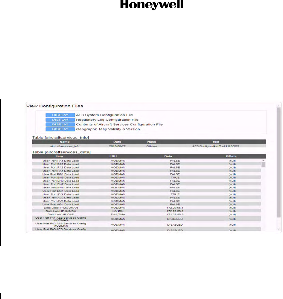
Page 7-98
3 Mar 2017
23-15-29
SYSTEM DESCRIPTION AND INSTALLATION MANUAL
JetWave™ System
© Honeywell International Inc. Do not copy without express permission of Honeywell.
To view and verify the AES system configuration, a web based GUI is supplied. The JetWave™
Ethernet configuration data can be viewed and verified by navigating to the “Contents of Aircraft
Services Configuration Files” page from “Configuration Files” under the Other Information & Control
menu. Figure 6-4 shows the typical configuration file Information page.
The network status and the VLAN ID can be viewed as shown in Figure 6-11.
The IP address assigned can be viewed by pressing the “Display” tab of the Contents of Aircraft
Configuration File as shown in Figure 7-9.
Figure 7-9. Contents of Aircraft Services Configuration File
There are a number of functions that an Ethernet port can support namely, data traffic, data loading,
GUI, AES logs extraction (maintenance function) and status/control (through the SNMP).
The terminal can be configured to indicate whether an Ethernet port supports traffic, data loading,
SNMP, etc, such as port PA1 configured for engineering SNMP and AES access services. Refer to
Figure 7-9. It contains the parameters that follow:
• User Port PA1/2/3/4/PG1/EN5/6/7/8/EG1/AV1/2/3/AG1 data load
• Data Load IP Modman
• Data Load IP KANDU
• Data Load IP OAE
• User Port PA1/2/3/4/PG1/EN5/6/7/8/EG1/AV1/2/3/AG1 AES services config Modman
• User Port PA1/2/3/4/PG1/EN5/6/7/8/EG1/AV1/2/3/AG1 AES services config KANDU
• User Port PA1/2/3/4/PG1/EN5/6/7/8/EG1/AV1/2/3/AG1 AES services config OAE
Draft as of 31 May 2017

Page 7-99
3 Mar 2017
23-15-29
SYSTEM DESCRIPTION AND INSTALLATION MANUAL
JetWave™ System
© Honeywell International Inc. Do not copy without express permission of Honeywell.
• User Port PA1/2/3/4/PG1/EN5/6/7/8/EG1/AV1/2/3/AG1 AES services IP Modman
• User Port PA1/2/3/4/PG1/EN5/6/7/8/EG1/AV1/2/3/AG1 AES services IP KANDU
• User Port PA1/2/3/4/PG1/EN5/6/7/8/EG1/AV1/2/3/AG1 AES services IP OAE
• User Port AES services IP subnet
•User Port PA1/2/3/4/PG1/EN5/6/7/8/EG1/AV1/2/3/AG1 traffic services
• User Port IP filter 1 thru 150.
Once the items have been loaded into the APM the Modman reads the APM once at power-on and
passes the appropriate data to the relevant LRU or uses the information locally.
(1) If the Ethernet port is not active, do as follows:
(a) Check the APM settings, as follows:
1Make sure that the port is enabled.
2Check system errors.
3Check for system reporting No layer 1 or No traffic faults.
(b) Is the device connecting to it operating correctly? If so, check the wiring.
(2) It there is poor performance on one port only, do as follows:
(a) Check for port reporting high packet loss. If so, check wiring and verify that there is
traffic.
(3) If not supplying access to the correct services, do as follows:
(a) Make sure the APM is configured for the correct services.
(b) Make sure the APM is configured to access the correct VLANs.
Check with the service provider to make sure that the VLANs have been correctly configured for
the terminal.
Draft as of 31 May 2017

Page 7-100
3 Mar 2017
23-15-29
SYSTEM DESCRIPTION AND INSTALLATION MANUAL
JetWave™ System
© Honeywell International Inc. Do not copy without express permission of Honeywell.
Blank Page
Draft as of 31 May 2017

Page 8-1
3 Mar 2017
23-15-29
SYSTEM DESCRIPTION AND INSTALLATION MANUAL
JetWave™ System
© Honeywell International Inc. Do not copy without express permission of Honeywell.
SECTION 8
MAINTENANCE AND REPAIR
8.1 Maintenance Requirements
(1) The maintenance-free design of the JetWave™ AES system does not require field
maintenance to maintain airworthiness.
(2) Maintenance of the JetWave™ AES system is limited to replacement of LRUs on verified
failure.
(3) OAE do not require field maintenance, such as lubrication of moving parts.
(4) If functional problems occur, the BITE can identify the faulty JetWave™ AES LRU and the
Modman collates this information which can be accessed through the GUI provided. Refer to
BITE Philosophy on page 7-8 of this document for information on how to access the BITE
data.
If replacement of an LRU is deemed necessary, in consultation with the customer's authorized JetWave
product support, It is strongly recommended that all repairs be performed only at the Honeywell
authorized facility.
Only qualified technical personnel, familiar with avionics systems, should perform the test procedures
provided in this document. Before performing any test or fault isolation procedures, read the safety
advisories.
•Remove the primary AC power delivered to the KANDU via aircraft circuit breaker. This
will power down the KANDU, including the 38.5 VDC and the 24 VDC power supply to
the FMA or TMA.
• Wait 1 minute following the removal of power to KANDU before attempting cable
disconnect from FMA or TMA, or any physical contact with the FMA or TMA.
• Disconnect FMA or TMA Plug P1 and measure the voltage across Pin A and Pin B using
a voltmeter (38.5 VDC voltage line). The measurement should not exceed 1 VDC.
• Disconnect FMA or TMA Plug P3 and measure the voltage across Pin 5 and Pin 6 using
a voltmeter (24 VDC voltage line). The measurement should not exceed 1 VDC.
8.2 Continued Airworthiness, FAR 25.1529
The sections that follow supply instructions for continued airworthiness for the JetWave™ AES system.
The sections that follow are supplied in response to Federal Aviation Regulation 25.1529, Instructions for
Continued Airworthiness.
8.3 Airworthiness Limitations
(1) Installation of the JetWave™ AES OAE assembly and LRUs on an aircraft by supplemental
type certificate (STC) or Form 337 obligates the aircraft operator to include the maintenance
information supplied by this manual in the operator’s Aircraft Maintenance manual and the
operator’s Aircraft Scheduled Maintenance Program.
Draft as of 31 May 2017

Page 8-2
3 Mar 2017
23-15-29
SYSTEM DESCRIPTION AND INSTALLATION MANUAL
JetWave™ System
© Honeywell International Inc. Do not copy without express permission of Honeywell.
(2) It is recommended that this section be appended to the Airplane Maintenance Manuals. The
information contained herein supplements the Airplane Maintenance Manuals in areas
covered by the JetWave™ AES FMA/TMA installation.
(3) It is recommended to consult basic Airplane Maintenance Manuals for limitations and
procedures not contained in this supplement. The inspections and airworthiness limitations
specified in this section are FAA approved.
(4) Aircraft Manufacturers may also impose return to service criteria on installed aircraft
equipment after lightning or bird strike events. This section and the sections that follow
specifies the inspections and other maintenance required under sections 433.16 and 91.403
of the Federal Aviation Regulations unless an alternative program has been FAA approved.
Initial and recurring inspections of the JetWave™ AES OAE assembly and LRUs and its associated
provisions are required. Specific inspection intervals are contained in Table 8-1.
8.4 General Instructions for Inspection
This section provides general instructions for the inspection of the JetWave™ AES OAE assembly and
LRUs.
(1) Gain access to the installation location on the fuselage for fuselage mount antenna assembly
or to the top of the aircraft vertical stabilizer in the case of tail mount antenna assembly
(2) Clean all visible surfaces of the antenna, radome assembly, and base plate.
(3) Do the inspections and checks presented in Electrical and Mechanical Inspection and Check.
(4) Remove the primary AC power delivered to the KANDU via aircraft circuit breaker. This will
power down the KANDU, including the 38.5 VDC and the 24 VDC power supply to the
FMA/TMA.
(5) Wait 1 minute following the removal of power to KANDU before attempting cable disconnect
from FMA/TMA, or any physical contact with the FMA/TMA.
(6) In case of FMA, disconnect FMA Plug P1 and measure the voltage across Pin A and Pin B
using a voltmeter (38.5 VDC voltage line). The measurement should not exceed 1 VDC.
(7) In case of TMA, disconnect TMA Plug P22 and measure the voltage across Pin G and Pin H
using a voltmeter (38.5 VDC voltage line). The measurement should not exceed 1 VDC.
(8) In case of FMA, disconnect FMA Plug P3 and measure the voltage across Pin 5 and Pin 6
using a voltmeter (24 VDC voltage line). The measurement should not exceed 1 VDC.
(9) In case of TMA, disconnect TMA Plug P22 and measure the voltage across Pin U and Pin V
(TMA) using a voltmeter (24 VDC voltage line). The measurement should not exceed 1 VDC.
Draft as of 31 May 2017

Page 8-3
3 Mar 2017
23-15-29
SYSTEM DESCRIPTION AND INSTALLATION MANUAL
JetWave™ System
© Honeywell International Inc. Do not copy without express permission of Honeywell.
8.5 Electrical and Mechanical Inspection and Check
Periodic inspections of the mechanical and electrical interfaces of the JetWave™ AES OAE assembly and
LRUs to the aircraft should be completed as defined by the governing airworthiness body (such as
Transport Canada, the FAA, or the JAA) Instructions for Continued Airworthiness for the installation.
For the general guidelines refer to Visual Inspection and Check and Scheduled Maintenance and
Inspections sections.
8.6 Instructions for Continued Airworthiness
This section supplies the special instructions and maintenance requirements for continued airworthiness
of the JetWave™ AES subsystems.
JetWave™ AES OAE assembly and LRUs are considered “On-Condition” units. No additional or
routine maintenance is required for the on-condition JetWave™ AES OAE assembly and LRUs.
If a JetWave™ AES OAE assembly or an LRU is inoperative, do as follows:
(a) Collar applicable switches and circuit breakers
(b) Secure cables and wiring
(c) Remove the unit
(d) Placard the JetWave™ AES LRU and associated items as “inoperative” in accordance
with the Aircraft Maintenance Manual (AMM)
(e) Before flight, do as follows:
(f) Record the removal of the unit in the aircraft log book
(g) Revise the equipment list. Refer to section 91.213 of the FAR or the aircraft’s Minimum
Equipment List (MEL)
(h) Revise the weight and balance data as applicable.
(i) In case of Modman replacement, the VAR/DP needs to be notified so that the system is
recommissioned to the new terminal ID.
JetWave™ AES system LRUs are not field-repairable. Return the faulty LRU(s) to the Honeywell
authorized facility for repair.
Install repaired or replacement LRUs on the aircraft in accordance with the installation instructions
supplied in this manual. Refer to ARINC 615A Software Data Load Process on page 5-1 for
instructions on how to bring the repaired or replacement LRU up to current software release.
Make sure that all repaired units operate correctly before you approve them for return to service,
with the operational verification tests and procedures provided in this SDIM. Approval for return to
service must be entered in the logbook as required by section 43.9 of the FAR.
Enter the approval for return to service in the appropriate logbook as required by FAR Section 43.9.
Add the scheduled maintenance tasks to the aircraft operator’s appropriate aircraft maintenance
program as follows:
Draft as of 31 May 2017

Page 8-4
3 Mar 2017
23-15-29
SYSTEM DESCRIPTION AND INSTALLATION MANUAL
JetWave™ System
© Honeywell International Inc. Do not copy without express permission of Honeywell.
(a) Recommended periodic scheduled servicing tasks: None required.
(b) Recommended periodic inspections:
(c) Scheduled maintenance inspections supplied in Table 8-1 and in accordance the
aircraft’s inspection and maintenance schedule.
(d) Recommended periodic scheduled preventative maintenance tests (to determine
system condition and/or latent failures): None required.
8.7 Visual Inspection and Check
Do the procedures that follow to examine the JetWave™ AES OAE assembly and LRUs after installation
of the unit onto the aircraft. Follow all approved safety standards and practices during the inspection.
WARNING: FAILURE TO DISCONNECT CIRCUIT BREAKERS CAN LEAD TO INJURY TO THE
OPERATOR AND DAMAGE TO THE EQUIPMENT.
(1) Disconnect all circuit breakers to the JetWave™ AES OAE assembly, LRUs and associated
systems.
(2) Visually examine the FMA or TMA radome for any damage or defects. Please refer to the
radome supplier’s Structural Repair Manual (SRM) for the specific radome inspection and
damage repair instructions.
(e) Saint Gobain SRM-100 is applicable to all radomes. FMA radome, PN
SCD-90401395-01, is covered specifically by Saint Gobain SRM-5249 structural repair
manual.
8.8 Scheduled Maintenance and Inspections
(1) The JetWave™ AES system does not require routine maintenance for continued
airworthiness.
(2) It is recommended to follow the Standard Practices Chapter of the Aircraft Maintenance
Manual and do all required inspections and repairs. Refer to Table 8-1 for scheduled
maintenance.
Table 8-1. Scheduled Maintenance
SI
No. Item Interval Potential Damage
Inspection Inspection
Lightning diverters In accordance with the
aircraft inspection
schedule and after flying in
known conditions of
lightning
Paint damage, structural
damage, de-lamination External visual
Fuselage mount
radome exterior,
radome skirt
exterior/tail mount
radome exterior
In accordance with the
aircraft inspection
schedule and after flying in
known conditions of
lightning/hail.
Paint damage, structural
damage, de-lamination,
puncture, dark
marks/streaking
External visual
Draft as of 31 May 2017

Page 8-5
3 Mar 2017
23-15-29
SYSTEM DESCRIPTION AND INSTALLATION MANUAL
JetWave™ System
© Honeywell International Inc. Do not copy without express permission of Honeywell.
Antenna interface
mount In accordance with the
aircraft inspection
schedule
Corrosion, loose, or
missing fasteners External visual
OAE – FMA/TMA
connectors In accordance with the
aircraft inspection
schedule
Corrosion, loose, or
missing connectors External visual
OAE-FMA/TMA
grounding and
bonding
In accordance with the
aircraft inspection
schedule
Non conform electrical
bonding External visual and
5 mΩ test
OAE-FMA/TMA
wiring In accordance with the
aircraft inspection
schedule
Chafing, cracks in
insulation, breaks External visual
KANDU
connectors In accordance with the
aircraft inspection
schedule
Corrosion, loose, or
missing connectors External visual
KANDU grounding
and bonding In accordance with the
aircraft inspection
schedule
Non conform electrical
bonding External visual and
5 mΩ test
Modman and
APM connectors In accordance with the
aircraft inspection
schedule
Corrosion, loose, or
missing connectors External visual
Modman and
APM grounding
and bonding
In accordance with the
aircraft inspection
schedule
Non conform electrical
bonding External visual and
5 mΩ test
Table 8-1. Scheduled Maintenance (Continued)
SI
No. Item Interval Potential Damage
Inspection Inspection
Draft as of 31 May 2017

Page 8-6
3 Mar 2017
23-15-29
SYSTEM DESCRIPTION AND INSTALLATION MANUAL
JetWave™ System
© Honeywell International Inc. Do not copy without express permission of Honeywell.
Blank Page
8.9 Unscheduled Maintenance
(1) Follow the Standard Practices Chapter of the Aircraft Maintenance Manual and do all the
required inspections and repairs, as shown in Table 8-2.
(2) JetWave™ AES system status can be viewed through the GUI. Refer to Checking Status
Information section for description.
(3) On the Modman LRU the status indicator LED is on the Modman front panel. The various
Modman status indications are shown in Table 8-3.
8.10 Repair Requirements
(1) The BITE functionality of JetWave™ AES system can identify the faulty LRU in the case of
any occurrence of functional problems and this can be accessed through Modman.
(2) In accordance with continued airworthiness instructions, if a JetWave™ AES system is
inoperative, use Standard Practices Chapter of the Aircraft Maintenance Manual to:
• Remove the unit
• Secure cables and wiring
• Collar applicable switches and circuit breakers, and placard them as “inoperative”.
Before flight, revise the equipment list and weight and balance data as applicable, and record the removal
of the unit in the log book. Refer to section 91.213 of the FAR or the aircraft’s minimum equipment list. All
repairs must be done at the Honeywell factory.
Table 8-2. Unscheduled Maintenance
Item Potential Damage Inspection
JetWave™ AES FMA
OAE/TMA OAE Heavy rain/hail Paint erosion External visual
bird strike Paint damage/radome
puncture External visual
JetWave™ AES
system Failure NA NA Removal
Table 8-3. Modman LED Status Indications
Status LED Mode
Off No electrical power/electrical power is
supplied but prior to boot.
Flash green at a minimum
of 10 seconds Modman initialization
On - green Modman in normal operation
On - red Modman in Fault Mode
Draft as of 31 May 2017

Page A-1
3 Mar 2017
23-15-29
SYSTEM DESCRIPTION AND INSTALLATION MANUAL
JetWave™ System
© Honeywell International Inc. Do not copy without express permission of Honeywell.
APPENDIX A
1. RTCA/DO-160G Environmental Characteristics
A. Modman
The following characteristics are taken from the core equipment qualification program and do not
reflect any additional qualification conducted on a per installation basis.
Section Condition Category
4 Temperature and altitude A1(V)
NOTE: Below 5˚F (-15˚C), user services are not offered. Altitude for all units extended to 55,000
feet (16,764 m) during the qualification test. Overpressure 28.9 PSI (199 kPa), Decompression
6,000 to 55,000 (1828.8 to 16,764 m) in 2 seconds.
5 Temperature variation B
6 Humidity B
7 Operational shocks and crash safety B
8 Vibration CAT S, CURVE B2
9 Explosive atmosphere X - not required
10 Waterproofness Y
11 Fluids specification X - not required
12 Sand and dust X - not required
13 Fungus resistance F
14 Salt fog X - not required
15 Magnetic effect A
16 Power input A (WF) HLPI
NOTE: Extended low frequency operation to 320 Hz.
17 Voltage spike A
NOTE: Extended to 1,000 volts.
18 Audio frequency conducted susceptibility K
NOTE: Amplitude of applied signal to be 10% of nominal AC voltage.
19 Induced signal susceptibility ZW
NOTE: Extended low frequency operations to 320 Hz.
Draft as of 31 May 2017

Page A-2
3 Mar 2017
23-15-29
SYSTEM DESCRIPTION AND INSTALLATION MANUAL
JetWave™ System
© Honeywell International Inc. Do not copy without express permission of Honeywell.
20 Radio frequency susceptibility RR (custom)
NOTE:
Radiated: Additional subjections
SW: 0.4 to 8 GHz: 28 V/m (1 kHz square mod with greater than 90% depth switched on and off
at 1 Hz rate and 50% duty cycle).
PM: 0.4 to 8 GHz: 150 V/m (Pulse repetition frequency of 1 kHz and a duty cycle of 1%, switched
on and off at 1 Hz rate and 50% duty cycle). Pulse width is 10 µsec (1% of 1 kHz).
PM: 0.3 to 6 GHz: 20 V/m, (Pulse repetition frequency of 200 Hz and a duty cycle of 12.5%).
Pulse width is 625 μsec (12.5% of 200Hz).
21 Emissions of RF energy M
22 Lightning induced transient susceptibility A2K2L3
NOTE: Modified to extend single stroke to waveform 3 level 3 and multi-stroke to waveform 4
level 2.
23 Lightning direct effects X - not required
24 Icing X - not required
25 Electrostatic discharge A
26 Fire, flammability C - covers 14 CFR 25.853
Section Condition Category
Draft as of 31 May 2017

Page A-3
3 Mar 2017
23-15-29
SYSTEM DESCRIPTION AND INSTALLATION MANUAL
JetWave™ System
© Honeywell International Inc. Do not copy without express permission of Honeywell.
B. APM
Section Condition Category
4 Temperature and altitude A1(V)
NOTE: Altitude test extended to 50,000 feet (15,240 m). Overpressure 28.9 PSI (199 kPa),
Decompression 6,000 to 55,000 (1828.8 to 16,764 m) in 2 seconds.
5 Temperature variation B
6 Humidity B
7 Operational shocks and crash safety B
8 Vibration CAT S, CURVE B2
9 Explosive atmosphere X - not required
10 Waterproofness Y
11 Fluid susceptibility X - not required
12 Sand and dust X - not required
13 Fungus resistance F
14 Salt fog X - not required
15 Magnetic effect A
16 Power input X - not required
17 Voltage spike X - not required
18 Audio frequency conducted susceptibility X - not required
19 Induced signal susceptibility ZC
20 Radio frequency susceptibility RR
21 Emissions of RF energy M
22 Lightning induced transient susceptibility A2K2L3
NOTE: Modified to extend single stroke to waveform 3 level 3 and multi-stroke to waveform 4
level 2.
23 Lightning direct effects X - not required
24 Icing X - not required
25 Electrostatic discharge A
26 Fire, flammability C - covers 14 CFR 25
Draft as of 31 May 2017

Page A-4
3 Mar 2017
23-15-29
SYSTEM DESCRIPTION AND INSTALLATION MANUAL
JetWave™ System
© Honeywell International Inc. Do not copy without express permission of Honeywell.
C. KANDU
Section Condition Category
4 Temperature and altitude D2
NOTE: Altitude test extended to 51,000 feet (15,544.8 m). Overpressure 28.9 PSI (199 kPa),
Decompression 6,000 to 55,000 (1,828.8 to 16,764.0 m).
5 Temperature variation A
6 Humidity B
7 Operational shocks and crash safety E and B
8 Vibration CAT R, CURVE E
CAT R, CURVE E1
NOTE: The sinusoidal sweep rate not to exceed 0.5 octaves/minute.
9 Explosive atmosphere E
10 Waterproofness Y and R
11 Fluid susceptibility F
NOTE: De-ice Ethylene Glycol, Hydraulic fluid phosphate ester AS1241 Type IV and V.
12 Sand and dust D
13 Fungus resistance F
14 Salt fog S
15 Magnetic effect Z
16 Power input A (WF) HZPI
NOTE: Extended low frequency operation to 320 Hz.
NOTE: Power factor – leading greater than 0.98.
17 Voltage spike A (modified to 1,000 volts)
18 Audio frequency conducted susceptibility K (WF)
NOTE: RMS amplitude of the audio signal extended to not less than 10% of the maximum normal
AC input voltage and with a power source frequency of 320 Hz in addition to 360 Hz and 800 Hz.
19 Induced signal susceptibility CW
NOTE: Extended low frequency operation to 320 Hz.
NOTE: With current and distance modified to 50 A at a distance of 0.4 inch (10 mm) for section
19.3.1.
20 Radio frequency susceptibility RY
NOTE:
- 0.4 to 8 GHz: 150 V/m (Pulse repetition frequency of 1 kHz and a duty cycle of 1%, switched
on and off at a 1 Hz rate and 50% duty cycle). Pulse width is 10 μsec (1% of 1 kHz).
- 0.3 to 6 GHz: 20 V, (Pulse repetition frequency of 200 Hz and a duty cycle of 12.5%). Pulse
width is 625 μsec (12.5% of 200 Hz).
Draft as of 31 May 2017

Page A-5
3 Mar 2017
23-15-29
SYSTEM DESCRIPTION AND INSTALLATION MANUAL
JetWave™ System
© Honeywell International Inc. Do not copy without express permission of Honeywell.
21 Emissions of RF energy Q
NOTE:
Extension of conducted emissions limits to 200 MHz at 20 dBμA and power line limits from 30
MHz to 108 MHz at 20 dBμA.
Extension of radiated emissions to start at 45 dBμV/m at 150 kHz to 40 dBμV/m at 2 MHz, and
at 30 dBμV/m at 2 MHz to 25 dBμV/m at 25 MHz, and at 25 dBμV/m at 25 MHz to 26.3 dBμV/m
at 30 MHz, and at 36.3 dBμV/m at 30 MHz to 44.5 dBμV/m at 100 MHz.
All conducted emissions limits, including interconnecting bundles limits, are set in accordance
with Category Q power line limit levels.
22 Lightning induced transient susceptibility A3K3L3
NOTE: Extended to include pin injection waveform 5A level 2.
23 Lightning direct effects X - not required
24 Icing A
25 Electrostatic discharge A
26 Fire, flammability C - covers 14 CFR 25.853
Section Condition Category
Draft as of 31 May 2017

Page A-6
3 Mar 2017
23-15-29
SYSTEM DESCRIPTION AND INSTALLATION MANUAL
JetWave™ System
© Honeywell International Inc. Do not copy without express permission of Honeywell.
D. KRFU
Section Condition Category
4 Temperature and altitude D2
NOTE: Altitude test extended to 51,000 feet (15,544.8 m). Overpressure 28.9 PSI (199 kPa),
Decompression 6,000 to 55,000 (1,828.8 to 16,764.0 m).
5 Temperature variation A
6 Humidity B
NOTE: At least six spot checks required.
7 Operational shocks and crash safety E and B
8 Vibration CAT R, CURVE E
CAT R, CURVE E1
NOTE: The sinusoidal sweep rate not to exceed 0.5 octaves/minute.
9 Explosive atmosphere E
10 Waterproofness Y and R
11 Fluid susceptibility F
NOTE: Ethylene Glycol, Propylene Glycol, AEA Type 1, AEA Type 2.
12 Sand and dust D
13 Fungus resistance F
14 Salt fog S
15 Magnetic effect Z
16 Power input A (WF) HZPI
NOTE: Extended low frequency operation to 320 Hz.
NOTE: Power Factor – leading greater than 0.98.
17 Voltage spike A (modified to 1,000 volts)
18 Audio frequency conducted susceptibility K (WF)
NOTE: RMS amplitude of the audio signal extended to not less than 10% of the maximum normal
AC input voltage and with a power source frequency of 320 Hz in addition to 360 Hz and 800 Hz.
19 Induced signal susceptibility CW
NOTE: Extended low frequency operation to 320 Hz.
NOTE: Section 19.3.1 performed with 50 A at a distance of 0.4 inch (10 mm).
20 Radio frequency susceptibility MY
NOTEL:
- 0.4 to 8 GHz: 150 V/m (Pulse repetition frequency of 1 kHz and a duty cycle of 1%, switched
on and off at a 1 Hz rate and 50% duty cycle). Pulse width is 10 μsec (1% of 1 kHz).
- 0.3 to 6 GHz: 20 V/m, (Pulse repetition frequency of 200 Hz and a duty cycle of 12.5%). Pulse
width is 625 μsec (12.5% of 200 Hz).
Draft as of 31 May 2017

Page A-7
3 Mar 2017
23-15-29
SYSTEM DESCRIPTION AND INSTALLATION MANUAL
JetWave™ System
© Honeywell International Inc. Do not copy without express permission of Honeywell.
21 Emissions of RF energy P
NOTE:
Extension of conducted emissions limits to 200 MHz at 20 dBμA and power line limits from
30MHz to 108MHz at 20 dBμA.
Extension of radiated emissions to start at 45 dBμV/m at 150 kHz to 40 dBμV/m at 2 MHz, and
at 30 dBμV/m at 2 MHz to 25 dBμV/m at 25 MHz, and at 25 dBμV/m at 25 MHz to 26.3 dBμV/m
at 30 MHz, and at 36.3 dBμV/m at 30 MHz to 44.5 dBμV/m at 100 MHz.
22 Lightning induced transient susceptibility A3K3L3
NOTE: Extended to include pin injection waveform 5A level 2.
23 Lightning direct effects X - not required
24 Icing A
25 Electrostatic discharge A
26 Fire, flammability C - covers 14 CFR 25.853
Section Condition Category
Draft as of 31 May 2017

Page A-8
3 Mar 2017
23-15-29
SYSTEM DESCRIPTION AND INSTALLATION MANUAL
JetWave™ System
© Honeywell International Inc. Do not copy without express permission of Honeywell.
E. TMA
Section Condition Category
4 Temperature and altitude F2
5 Temperature variation A
6 Humidity B
7 Operational shocks and crash safety E
8 Vibration CAT R, CURVE E
CAT R, CURVE E1
9 Explosive atmosphere E and H
10 Waterproofness Y and W
11 Fluid susceptibility F (de-icing fluids)
NOTE: Ethylene Glycol.
12 Sand and dust D
13 Fungus resistance F
14 Salt fog S
15 Magnetic effect A
16 Power input X - not required
17 Voltage spike A
NOTE: Do DO-160G/17.0 on TMA with the KANDU attached as the UUT.
The length of test cable between TMA and KANDU shall be 40 ft (12 m).
18 Audio frequency conducted susceptibility R
NOTE:
A. Frequency range from 324 Hz to 650 Hz.
B. Do DO-160G/18.0 on TMA with the KANDU attached as the UUT.
The length of test cable between TMA and KANDU shall be 40 ft (12 m).
19 Induced signal susceptibility ZC
20 Radio frequency susceptibility YQ (custom)
NOTE: Q (custom) only - SW/CW (un-modulated) signal Operational:
200V/m for 100 MHz to 12 GHz
0.1 V/m 12 GHz to 16.6 GHz
No damage:
200V/m for 12 GHz to 16.6 GHz
0.1 V/m for 16.6 GHz to 18 GHz
21 Emissions of RF energy H
22 Lightning induced transient susceptibility A3K3L3 modified
NOTE: Pin Injection waveform 5A level 2. Single stroke WF 4, level 3 (extended to 300V/1000A),
Multi-stroke WF4 level 3 (extended to 120V/400A 1st stroke, 75V/150A subsequent strokes),
Extend WF5A level 3 (extended 120V/400A 1st stroke, 75V/150A subsequent strokes).
Draft as of 31 May 2017

Page A-9
3 Mar 2017
23-15-29
SYSTEM DESCRIPTION AND INSTALLATION MANUAL
JetWave™ System
© Honeywell International Inc. Do not copy without express permission of Honeywell.
23 Lightning direct effects X - not required
24 Icing B
25 Electrostatic discharge A
26 Fire, flammability C - covers 4 CFR 25.853
Section Condition Category
Draft as of 31 May 2017

Page A-10
3 Mar 2017
23-15-29
SYSTEM DESCRIPTION AND INSTALLATION MANUAL
JetWave™ System
© Honeywell International Inc. Do not copy without express permission of Honeywell.
F. FMA
Section Condition Category
4 Temperature and altitude F2
NOTE: Extended operating high to 194˚F (90˚C).
5 Temperature variation A
6 Humidity B
NOTE: At least six spot checks are required.
7 Operational shocks and crash safety B and E
8 Vibration CAT S, CURVE C
CAT R, CURVE C1
NOTE: The sinusoidal sweep rate not to exceed 0.5 octaves/minute
9 Explosive atmosphere E
10 Waterproofness Y and W
11 Fluid susceptibility - De-ice fluids only F
12 Sand and dust D
13 Fungus resistance F
14 Salt fog S
15 Magnetic effect B
16 Power input X - not required
17 Voltage spike X - not required
18 Audio frequency conducted susceptibility X - not required
19 Induced signal susceptibility ZC
20 Radio frequency susceptibility YQ
NOTE: Q (custom) only - SW/CW (un-modulated) signal Operational:
200V/m for 100 MHz to 12 GHz
0.1 V/m 12 GHz to 16.6 GHz
No damage:
200V/m for 12 GHz to 16.6 GHz
0.1 V/m for 16.6 GHz to 18 GHz
21 Emissions of RF energy H
NOTE:
Extension of conducted emissions limits to 200 MHz at 20 dBμA and power line limits from
30MHz to 152MHz at 20 dBμA.
All conducted emissions limits, including interconnecting bundles limits, are set in accordance
with Category H power line limit levels.
Radiated emissions to start at 40 dBμV/m at 2 MHz to 35 dBμV/m at 25 MHz, and at 35 dBμV/m
at 25 MHz to 44.6 dBμV/m at 100 MHz
Draft as of 31 May 2017

Page A-11
3 Mar 2017
23-15-29
SYSTEM DESCRIPTION AND INSTALLATION MANUAL
JetWave™ System
© Honeywell International Inc. Do not copy without express permission of Honeywell.
22 Lightning induced transient susceptibility A3K3L3
NOTE: Pin Injection waveform 5A level 125V/125A and 400V/4A. Single stroke WF 4, level 3
(extended to 300V/1000A), Multi-stroke WF4 level 3 (extended to 120V/400A 1st stroke,
60V/120A subsequent strokes).
23 Lightning direct effects X - not required
24 Icing B
25 Electrostatic discharge A
26 Fire, flammability C - covers 14 CFR 25.853
Section Condition Category
Draft as of 31 May 2017

Page A-12
3 Mar 2017
23-15-29
SYSTEM DESCRIPTION AND INSTALLATION MANUAL
JetWave™ System
© Honeywell International Inc. Do not copy without express permission of Honeywell.
Blank Page
Draft as of 31 May 2017

Page B-1
3 Mar 2017
23-15-29
SYSTEM DESCRIPTION AND INSTALLATION MANUAL
JetWave™ System
© Honeywell International Inc. Do not copy without express permission of Honeywell.
APPENDIX B
NOTE: The JetWave™ LRU labels do contain data such as Software Part No., Software Version
No. or Software Mod dots. To see the JetWave™LRUs hardware and software version and
part number, navigate to the Version and Manufacturing Information menu on the GUI.
1. Aircraft Information Sheet
2. JetWave™ AES Subsystem Components
A. JetWave™ AES OAE - FMA/TMA Installation Information Sheet
B. JetWave™ AES KANDU Installation Information Sheet
C. JetWave™ AES KRFU Installation Information Sheet
Owner
Tail Number
Serial Number
Model/Type
Part Number
Serial Number
Hardware Revision
Mod Status
Part Number
Serial Number
Hardware Revision
Mod Status
Part Number
Serial Number
Hardware Revision
Mod Status
Draft as of 31 May 2017

Page B-2
3 Mar 2017
23-15-29
SYSTEM DESCRIPTION AND INSTALLATION MANUAL
JetWave™ System
© Honeywell International Inc. Do not copy without express permission of Honeywell.
D. JetWave™ AES Modman Installation Information Sheet
E. JetWave™ AES APM Installation Information Sheet
Part Number
Serial Number
Hardware Revision
Mod Status
Part Number
Serial Number
Hardware Revision
Mod Status
Draft as of 31 May 2017

Page C-1
3 Mar 2017
23-15-29
SYSTEM DESCRIPTION AND INSTALLATION MANUAL
JetWave™ System
© Honeywell International Inc. Do not copy without express permission of Honeywell.
APPENDIX C
1. Installation Checklist
A. OAE-TMA Checklist
Aircraft Identification:
Name Signature Date
Installation/Checks completed by:
Approved/Witnessed by:
Section Parameter Item NA √Value
A. Maintenance Panel Applicability If the system is not wired to another
aircraft system, an installer provided
maintenance panel is required.
Discrete
output
connections
System available (Modman MP13E)
connected to a lamp
Data link available (Modman MP13F)
connected to a lamp
Discrete input
connections Local data load enable (Modman
MP10B) connected to a normally open
switch
Ground transmit enable (Modman
MP11D) connected to a normally open
switch
Public service disable (Modman
MP11E) connected to a normally open
switch
Modman reset (Modman MP10C)
connected to a normally open switch
Tx mute (KANDU J1D) connected to a
normally open switch
Ethernet port
connections AV1 (Modman TP BB1 thru 4)
connected to a RJ45 Ethernet connector
Additional
electrical
wiring
Electrically wire and interconnect in
accordance with Figure 4-34.
Draft as of 31 May 2017

Page C-2
3 Mar 2017
23-15-29
SYSTEM DESCRIPTION AND INSTALLATION MANUAL
JetWave™ System
© Honeywell International Inc. Do not copy without express permission of Honeywell.
A. Modman Physical Examine for physical damage.
Environmental conditions, refer to
Figure 4-22.
Mounting tray Install applicable 4-MCU tray, supplied
by customer.
Clearance Minimum 1 inch (25.4 mm) from top
surface and 0.5 inch (12.7 mm) from all
other surfaces
Electrical
connector ARINC 600 mating connector and pins,
refer to Table 4-1. ARINC 600
Connectors
ARINC 600 polarized pins
Electrical
bonding Bonding, refer to page 4-3.
Electrical
wiring Electrically wire and interconnect in
accordance with Figure 4-21 or
Figure 4-22 and Figure 4-34.
Electrical RF
coaxial Equalizer in the TX path
TX path loss, refer to Table 4-2. Modman
Cable Loss Values
Attenuator in the RX path
RX path loss, refer to Table 4-2.
Modman Cable Loss Values
NOTE: Input signal
range: -79 to -5 dBm.
Output signal range -30
to +5 dBm. Incross talk
requirement: -25 dBc.
Output cross talk
requirement: -40
dBc.APM
Physical Examine for physical damage.
Environmental conditions, refer to
Figure 4-21 and Figure 4-22.
Mounting Can be installed in any orientation, refer
to Figure 4-21 and Figure 4-22.
Use 0.164-32 UNC-2A corrosion
resistant mounting fasteners.
Do not exceed 25 in-lb (2.8 Nm) when
you torque the screws.
Electrical
bonding Electrically bond in accordance with
page 4-4.
Section Parameter Item NA √Value
Draft as of 31 May 2017

Page C-3
3 Mar 2017
23-15-29
SYSTEM DESCRIPTION AND INSTALLATION MANUAL
JetWave™ System
© Honeywell International Inc. Do not copy without express permission of Honeywell.
NOTE: Input signal
range: -79 to -5 dBm.
Output signal range -30
to +5 dBm. Incross talk
requirement: -25 dBc.
Output cross talk
requirement: -40 dBc.
(Cont)
Electrical
wiring Electrically wire and interconnect in
accordance with Figure 4-24 and
Figure 4-34.
Electrical
wiring - APM to
Modman
APM to Modman interconnect cable
shall use ARINC 664 compliant 2
Shielded Twisted Pair 24 AWG (or
Aerospace Grade Shielded Cat 5/Cat
5E Minimum). Part No. ECS 922404 or
Equivalent, with a maximum length of
9.8 feet (3 m).
4.3 KANDU Physical Examine for physical damage.
Environmental conditions, refer to
Figure 4-25 and Figure 4-26
Electrical
wiring Electrically wire and interconnect in
accordance with Figure 4-25,
Figure 4-26, and Figure 4-34.
Mounting Install location of KANDU is airframe
specific. KANDU could be installed in
unpressurized area near the tail
empennage of the aircraft or inside
pressurized area of the aircraft.
In case of KANDU install location is
inside pressurized location, the KANDU
to KRFU and KANDU to TMA
interconnect may be routed through a
Bulkhead Interface connector.
Electrical
wiring -
KANDU to
TMA
Refer to JetWave™ System Internal
LRU Installation, KANDU on page 4-8.
Electrical
wiring -
KANDU
bulkhead
interface
Refer to JetWave™ System Internal
LRU Installation, KANDU on page 4-8.
Section Parameter Item NA √Value
Draft as of 31 May 2017

Page C-4
3 Mar 2017
23-15-29
SYSTEM DESCRIPTION AND INSTALLATION MANUAL
JetWave™ System
© Honeywell International Inc. Do not copy without express permission of Honeywell.
4.6 KRFU Physical Examine for physical damage.
Environmental conditions, refer to
Figure 4-27, Figure 4-28, or Figure 4-29
depending on configuration used.
Install the thermal pad in accordance
with KRFU on page 4-16.
The KRFU is installed with the TMA,
refer to OAE TMA Installation Procedure
on page 4-30.
The KRFU feet are configured differently
depending on the part number ordered.
Make sure feet are in the correct
configuration for the aircraft application.
Waveguide Make sure the waveguide is connected
before powering the KRFU.
Waveguide -
KRFU to TMA Connection must be WR28 for TX and
coaxial cable for RX.
The TX interconnect path loss
The RX interconnect path loss
RX connection at the KRFU requires a
WR42 to coax transition adapter at the
KRFU J4
Electrical
wiring Electrically wire and interconnect in
accordance with outline drawing
Figure 4-27, Figure 4-28, or Figure 4-29
and interconnect drawing Figure 4-34.
Electrical
bonding Electrically bond in accordance with
page 4-18.
(b) OAE TMA
Installation Procedure Physical Refer to OAE TMA Installation
Procedure.
TMA mounting Refer to OAE TMA Installation
Procedure.
TMA interface
mount
brackets
Refer to OAE TMA Installation
Procedure.
Section Parameter Item NA √Value
Draft as of 31 May 2017

Page C-5
3 Mar 2017
23-15-29
SYSTEM DESCRIPTION AND INSTALLATION MANUAL
JetWave™ System
© Honeywell International Inc. Do not copy without express permission of Honeywell.
(b) OAE TMA
Installation Procedure
(Cont)
TMA install Refer to OAE TMA Installation
Procedure.
TMA radome
and radome
fairing
Depending on the airframe, there may
be a need to install radome fairing
which adapts to the tail empennage of
the aircraft, consult aircraft OEM.
Radome and fairing installation is
aircraft specific. Refer to aircraft
specific SDIM for details.
NOTE: Before removing the Tail
Mount Radome, Honeywell
recommends manually
steering the TMA to a safe
antenna orientation position
using the JetWave™ GUI. The
TMA parking position is
included in the AES System
Configuration File, which can
be accessed through the GUI
web interface and by
navigating to Configuration
File page. Consult aircraft
specific SDIM for detailed
instructions.
TMA bonding Electrically bond in accordance with
Figure 4-30.
TMA
alignment Automatic alignment, manual
alignment, or command, refer to TMA
Alignment on page 2-23 and Inspection
of Waveguide on page 4-43
Section Parameter Item NA √Value
Draft as of 31 May 2017

Page C-6
3 Mar 2017
23-15-29
SYSTEM DESCRIPTION AND INSTALLATION MANUAL
JetWave™ System
© Honeywell International Inc. Do not copy without express permission of Honeywell.
B. A791 Based OAE-FMA with the AIM Checklist
Section Parameter Item NA √Value
A. Maintenance Panel Applicability If the system is not wired to another
aircraft system, an installer provided
maintenance panel is required.
Discrete
output
connections
System available (Modman MP13E)
connected to a lamp
Data link available (Modman MP13F)
connected to a lamp
Discrete input
connections Local data load enable (Modman
MP10B) connected to a normally open
switch
Ground transmit enable (Modman
MP11D) connected to a normally open
switch
Public service disable (Modman
MP11E) connected to a normally open
switch
Modman reset (Modman MP10C)
connected to a normally open switch
Tx mute (KANDU J1D) connected to a
normally open switch
Ethernet port
connections AV1 (Modman TP BB1 thru 4)
connected to a RJ45 Ethernet connector
Additional
electrical
wiring
Electrically wire and interconnect in
accordance with Figure 4-35 thru
Figure 4-37.
A. Modman Physical Examine for physical damage.
Environmental conditions, refer to
Figure 4-21 or Figure 4-22.
Mounting tray Install applicable 4-MCU tray, supplied
by customer.
Draft as of 31 May 2017

Page C-7
3 Mar 2017
23-15-29
SYSTEM DESCRIPTION AND INSTALLATION MANUAL
JetWave™ System
© Honeywell International Inc. Do not copy without express permission of Honeywell.
A. Modman (Cont) Clearance Minimum 1 inch (25.4 mm) from top
surface and 0.5 inch (12.7 mm) from all
other surfaces
Electrical
connector ARINC 600 mating connector and pins,
refer to Table 4-1. ARINC 600
Connectors
ARINC 600 polarized pins
Electrical
bonding Bonding, refer to page 4-3
Electrical
wiring Electrically wire and interconnect in
accordance with Figure 4-21 or
Figure 4-22 and Figure 4-35 thru
Figure 4-37, depending on the
configuration being used.
Electrical RF
coaxial Equalizer in the TX path
TX path loss, refer to Table 4-2. Modman
Cable Loss Values
Attenuator in the RX path
RX path loss, refer to Table 4-2.
Modman Cable Loss Values
NOTE: Input signal
range: -79 to -5 dBm.
Output signal range -30
to +5 dBm. Incross talk
requirement: -25 dBc.
Output cross talk
requirement: -40
dBc.APM
Physical Examine for physical damage.
Environmental conditions, refer to
Figure 4-21 and Figure 4-22.
Mounting Can be installed in any orientation. Refer
Figure 4-21 and Figure 4-22.
Use 0.164-32 UNC-2A corrosion
resistant mounting fasteners.
Do not exceed 25 in-lb (2.8 Nm) when
you torque the screws.
Electrical
bonding Electrically bond in accordance with
page 4-4.
Electrical
wiring Electrically wire and interconnect in
accordance with Figure 4-24 and
Figure 4-35 thru Figure 4-37, depending
on the configuration being used.
Section Parameter Item NA √Value
Draft as of 31 May 2017

Page C-8
3 Mar 2017
23-15-29
SYSTEM DESCRIPTION AND INSTALLATION MANUAL
JetWave™ System
© Honeywell International Inc. Do not copy without express permission of Honeywell.
NOTE: Input signal
range: -79 to -5 dBm.
Output signal range -30
to +5 dBm. Incross talk
requirement: -25 dBc.
Output cross talk
requirement: -40 dBc.
(Cont)
Electrical
wiring - APM to
Modman
APM to Modman interconnect cable
shall use ARINC 664 compliant 2
Shielded Twisted Pair 24 AWG (or
Aerospace Grade Shielded Cat 5/Cat
5E Minimum). Part No. ECS 922404 or
Equivalent, with a maximum length of
9.8 feet (3 m).
4.3 KANDU Physical Examine for physical damage.
Environmental conditions, refer to
Figure 4-25 or Figure 4-26.
Mounting Install location of KANDU is airframe
specific.
The KANDU is installed inside a
pressurized location, the KANDU to
KRFU and KANDU to FMA
interconnect are routed through a
Bulkhead Interface connectors.
Electrical
Wiring
KANDU-FMA
Refer to JetWave™ System Internal
LRU Installation, KANDU on page 4-8.
4.6 KRFU Physical Examine for physical damage.
Environmental conditions, refer to
Figure 4-27, Figure 4-28, or Figure 4-29
depending on configuration used.
Install the thermal pad in accordance
with KRFU on page 4-16.
The KRFU is installed with the FMA,
refer to FMA Installation Procedure on
page 4-24.
The KRFU feet are configured differently
depending on the part number ordered.
Make sure feet are in the correct
configuration for the aircraft application.
Waveguide Make sure the waveguide is connected
before powering the KRFU.
Waveguide -
KRFU to FMA Connection must be WR28 for TX and
coaxial cable for RX.
The TX interconnect path loss
Section Parameter Item NA √Value
Draft as of 31 May 2017

Page C-9
3 Mar 2017
23-15-29
SYSTEM DESCRIPTION AND INSTALLATION MANUAL
JetWave™ System
© Honeywell International Inc. Do not copy without express permission of Honeywell.
4.6 KRFU (Cont) Waveguide -
KRFU to FMA
(Cont)
The RX interconnect path loss
RX connection at the KRFU requires a
WR42 to coax transition adapter at the
KRFU J4.
Electrical
wiring Electrically wire and interconnect in
accordance with outline drawing
Figure 4-27, Figure 4-28, or Figure 4-29
and interconnect drawing Figure 4-35 or
Figure 4-37, depending on the
configuration being used.
Electrical
bonding Electrically bond in accordance with
page 4-18.
N. FMA Installation
Procedure
Physical Examine the FMA AIM for physical
damage.
Examine the FMA assembly for
physical damage.
Examine the radome for physical
damage. Refer to Figure 4-32.
Environmental conditions, refer to
Figure 4-31.
Positioning The aircraft fuselage mount OAE must
be mounted on the top of the fuselage.
FMA AIM Refer to Fuselage Mount Antenna (If
applicable) (8).
FMA Install Refer to Fuselage Mount Antenna (If
applicable) (8).
FMA radome Attach the radome assembly onto the
AIM.
FMA bonding Electrically bond in accordance with
page 4-16.
FMA
alignment Automatic alignment, manual
alignment, or command, refer to FMA
Alignment on page 2-39 and Inspection
of Waveguide on page 4-43.
Section Parameter Item NA √Value
Draft as of 31 May 2017

Page C-10
3 Mar 2017
23-15-29
SYSTEM DESCRIPTION AND INSTALLATION MANUAL
JetWave™ System
© Honeywell International Inc. Do not copy without express permission of Honeywell.
C. Non-A791 Based OAE-FMA with the LAIM Checklist
Section Parameter Item NA √Value
A. Maintenance Panel Applicability If the system is not wired to another
aircraft system, an installer provided
maintenance panel is required.
Discrete
output
connections
System available (Modman MP13E)
connected to a lamp
Data link available (Modman MP13F)
connected to a lamp
Discrete input
connections Local data load enable (Modman
MP10B) connected to a normally open
switch
Ground transmit enable (Modman
MP11D) connected to a normally open
switch
Public service disable (Modman
MP11E) connected to a normally open
switch
Modman reset (Modman MP10C)
connected to a normally open switch
Tx mute (KANDU J1D) connected to a
normally open switch
Ethernet port
connections AV1 (Modman TP BB1 thru 4)
connected to a RJ45 Ethernet connector
Additional
electrical
wiring
Electrically wire and interconnect in
accordance with Figure 4-35 thru
Figure 4-37, depending on the
configuration being used.
A. Modman Physical Examine for physical damage.
Environmental conditions, refer to
Figure 4-21 or Figure 4-22.
Mounting tray Install applicable 4-MCU tray, supplied
by customer.
Clearance Minimum 1 inch (25.4 mm) from top
surface and 0.5 inch (12.7 mm) from all
other surfaces.
Electrical
connector ARINC 600 mating connector and pins,
refer to Table 4-1. ARINC 600
Connectors
ARINC 600 polarized pins
Draft as of 31 May 2017

Page C-11
3 Mar 2017
23-15-29
SYSTEM DESCRIPTION AND INSTALLATION MANUAL
JetWave™ System
© Honeywell International Inc. Do not copy without express permission of Honeywell.
A. Modman (Cont) Electrical
bonding Bonding, refer to page 4-3
Electrical
wiring Electrically wire and interconnect in
accordance with Figure 4-21 or
Figure 4-22 and Figure 4-35thru
Figure 4-37, depending on the
configuration being used.
Electrical RF
coaxial Equalizer in the TX path
TX path loss, refer to Table 4-2. Modman
Cable Loss Values
Attenuator in the RX path
RX path loss, refer to Table 4-2.
Modman Cable Loss Values
NOTE: Input signal
range: -79 to -5 dBm.
Output signal range -30
to +5 dBm. Incross talk
requirement: -25 dBc.
Output cross talk
requirement: -40
dBc.APM
Physical Examine for physical damage.
Environmental conditions, refer to
Figure 4-21 and Figure 4-22.
Mounting Can be installed in any orientation. Refer
to Figure 4-21 and Figure 4-22.
Use 0.164-32 UNC-2A corrosion
resistant mounting fasteners.
Do not exceed 25 in-lb (2.8 Nm) when
you torque the screws.
Electrical
bonding Electrically bond in accordance with
page 4-4.
Electrical
wiring Electrically wire and interconnect in
accordance with Figure 4-23 and
Figure 4-35 thru Figure 4-37, depending
on the configuration being used.
Electrical
wiring - APM to
Modman
APM to Modman interconnect cable
shall use ARINC 664 compliant 2
Shielded Twisted Pair 24 AWG (or
Aerospace Grade Shielded Cat 5/Cat
5E Minimum). Part No. ECS 922404 or
Equivalent, with a maximum length of
9.8 feet (3 m).
Section Parameter Item NA √Value
Draft as of 31 May 2017

Page C-12
3 Mar 2017
23-15-29
SYSTEM DESCRIPTION AND INSTALLATION MANUAL
JetWave™ System
© Honeywell International Inc. Do not copy without express permission of Honeywell.
4.3 KANDU Physical Examine for physical damage.
Environmental conditions, refer to
Figure 4-25 or Figure 4-26.
Electrical
wiring Electrically wire and interconnect in
accordance with Figure 4-25 or
Figure 4-26 and Figure 4-34, thru
Figure 4-37, depending on the
configuration being used.
Mounting Install location of KANDU is airframe
specific.
The KANDU is installed inside a
pressurized location, the KANDU to
KRFU and KANDU to FMA
interconnect are routed through a
Bulkhead Interface connectors.
Electrical
wiring -
KANDU -FMA
Refer to KANDU (1).
Electrical
bonding Electrically bond in accordance with
page 4-10.
KANDU bonding to the aircraft must be
achieved through the mounting
structure (fasteners) and KANDU
A3J1-A.
The bulkhead interface connectors
should be electrically bonded to the
aircraft.
4.6 KRFU Physical Examine for physical damage.
Environmental conditions, refer to
Figure 4-27, Figure 4-28, or Figure 4-29
depending on configuration used.
Install the thermal pad in accordance
with KRFU on page 4-16.
The KRFU is installed with the FMA.
refer to FMA Installation Procedure on
page 4-24.
Section Parameter Item NA √Value
Draft as of 31 May 2017

Page C-13
3 Mar 2017
23-15-29
SYSTEM DESCRIPTION AND INSTALLATION MANUAL
JetWave™ System
© Honeywell International Inc. Do not copy without express permission of Honeywell.
4.6 KRFU (Cont) Physical
(Cont) The KRFU feet are configured differently
depending on the part number ordered.
Make sure feet are in the correct
configuration for the aircraft application.
Waveguide Make sure the waveguide is connected
before powering the KRFU.
Waveguide -
KRFU to FMA Connection must be WR28 for TX and
coaxial cable for RX.
The TX interconnect path loss
The RX interconnect path loss
RX connection at the KRFU requires a
WR42 to coax transition adapter at the
KRFU J4.
Electrical
wiring Electrically wire and interconnect in
accordance with outline drawing
Figure 4-27, Figure 4-28, or Figure 4-29
and interconnect drawing Figure 4-34
thru Figure 4-37, depending on the
configuration being used.
Electrical
bonding Electrically bond in accordance with
page 4-18.
I. FMA Installation
Procedure Physical Examine the FMA AIM for physical
damage.
Examine the FMA assembly for physical
damage.
Examine the radome for physical
damage. Refer to Figure 4-32.
Environmental conditions, refer to
Figure 4-31.
Positioning The aircraft fuselage mount OAE must
be mounted on the top of the fuselage
for clear satellite communications.
FMA LAIM Refer to Fuselage Mount Antenna (If
applicable) (8).
Install radome
skirt fairing Install and attach the radome skirt
fairing to fuselage with 39 fasteners.
Section Parameter Item NA √Value
Draft as of 31 May 2017

Page C-14
3 Mar 2017
23-15-29
SYSTEM DESCRIPTION AND INSTALLATION MANUAL
JetWave™ System
© Honeywell International Inc. Do not copy without express permission of Honeywell.
I. FMA Installation
Procedure (Cont) Install radome
skirt fairing Install and attach the radome skirt
fairing to fuselage with 39 fasteners.
FMA install Refer to Fuselage Mount Antenna (If
applicable) (8).
FMA radome Attach the radome assembly onto the
radome skirt fairing.
FMA bonding Electrically bond in accordance with
page 4-16.
FMA
alignment Automatic alignment, manual
alignment, or command, refer to FMA
Alignment on page 2-39 and Inspection
of Waveguide on page 4-43.
Section Parameter Item NA √Value
Draft as of 31 May 2017

Page D-1
3 Mar 2017
23-15-29
SYSTEM DESCRIPTION AND INSTALLATION MANUAL
JetWave™ System
© Honeywell International Inc. Do not copy without express permission of Honeywell.
APPENDIX D
1. List of Airframe Specific Information Required for JetWave™ System Configuration
A Honeywell proprietary configuration tool is used to generate the JetWave™ configuration files. Information
as listed in the tables below is to be provided to Honeywell for generation of JetWave™ configuration files.
Table D-1. Value Added Reseller (VAR/DP)
Name of the Service Provider
Table D-2. Aircraft Information
Aircraft Model/Type Tail Number Serial Number Expected Activation Date
Table D-3. Air Data Inertial Reference Unit/Multi Mode Receiver
ADIRU Part Number MMR Part Number
Table D-4. ARINC 429 Labels
ARINC 429 Interface Speed Interface Bus Speed
ARINC 429 IRS Interface Bus Speed
ARINC 429 Aircraft State Interface Bus Speed
Label
Number Label Name Accuracy Label
Latency
Total
Latency
(Msec)
Minimum
Transmission
Rate (Msec) Jitter
314 True Heading
125 UTC Time
150 UTC Time
260 Date
254 Present Position – Latitude
255 Present Position – Longitude
261 Altitude
132 True Heading
175 Ground Speed
Draft as of 31 May 2017

Page D-2
3 Mar 2017
23-15-29
SYSTEM DESCRIPTION AND INSTALLATION MANUAL
JetWave™ System
© Honeywell International Inc. Do not copy without express permission of Honeywell.
313 True Track
315 Horizontal Stabilization
324 Pitch Angle
325 Roll Angle
330 Yaw Rate
326 Pitch Rate
327 Roll Rate
110 GNSS Latitude
111 GNSS Longitude
112 GNSS Ground Speed
76 GNSS Altitude (MSL)
270 IRS Discrete Status
312 Ground speed
Table D-4. ARINC 429 Labels (Continued)
ARINC 429 Interface Speed Interface Bus Speed
ARINC 429 IRS Interface Bus Speed
ARINC 429 Aircraft State Interface Bus Speed
Label
Number Label Name Accuracy Label
Latency
Total
Latency
(Msec)
Minimum
Transmission
Rate (Msec) Jitter
Draft as of 31 May 2017

Page D-3
3 Mar 2017
23-15-29
SYSTEM DESCRIPTION AND INSTALLATION MANUAL
JetWave™ System
© Honeywell International Inc. Do not copy without express permission of Honeywell.
Table D-5. Airframe Structural Blockage Information
Blockage Angle Value in Degrees Remarks
Blockage Angle a Angle “a” is the angle between the horizontal plane
where the antenna emitting point is located and outer
tip of the Horizontal Tail Plane (HTP).
Blockage Angle b Angle “b” is between horizontal plane where antenna
emitting point is located and outer tip of wing
(including vortex eliminators, if present).
Blockage Angle c Angle “c” refers to the point of the wing, where an
antenna radiating at -10-degrees elevation would find
the wing’s leading edge.
Blockage Angle d Angle “d” refers to the outer, aft-most tip of the wing
(including vortex eliminators, if present).
Blockage Angle e Angle “e” provides the azimuth range of the Vertical
Tail Plane (VTP) region of blockage in its broadest
case.
Blockage Angle f Angle “f” is between the fuselage centerline and the
outer, forward-most tip of the HTP.
Blockage Angle h Angle “h” provides the Vertical Tail Plane (VTP)
region of blockage in elevation from -10 degrees up.
Blockage Angle i Angle “i” is between the horizontal plane where the
antenna emitting point is located and upper,
forward-most part of the fuselage.
Blockage Angle k Angle “k” is the angle between the horizontal plane
where the antenna emitting point is located and the
aft-most tip of the HTP.
Blockage Angle m Angle “m” is between the horizontal plane where the
antenna emitting point is located and the HTP leading
edge root (forward-most joint to fuselage).
Blockage Angle p Angle “p” is from the emitter point to upper, aft-most
wing tip (including vortex eliminators, if present).
Draft as of 31 May 2017
Page D-4
3 Mar 2017
23-15-29
SYSTEM DESCRIPTION AND INSTALLATION MANUAL
JetWave™ System
© Honeywell International Inc. Do not copy without express permission of Honeywell.
NOTE:
• All zenith view (from above) angles, except for “e,” are measured from the aircraft
longitudinal axis, being 0 degrees at the stern.
• All side view angles are measured from the aircraft longitudinal axis, being 0 degrees at
the plane where the antenna emitter is located.
Refer to ARINC Characteristic 791 Mark I Aviation Ku-band and Ka-Band Satellite Communication System,
Part 1- Physical Installation and Aircraft Interfaces for Aircraft blockage map parameters.
Table D-6. Weight on Wheels
Weight on Wheels Discrete Input Available Y/N Polarity of Weight on Wheels Discrete
Signal
Table D-7. Ground Transmit Enable
Ground Transmit Enable Discrete Y/N Polarity of Ground Transmit Enable
Discrete
Table D-8. ARINC Tx Mute and Tail Sector Mute Switch
ARINC Tx Mute Connected Yes/No
Tail Sector Mute Switch Wired Yes/No
Table D-9 ARINC791 Equipped
Y N Frame Number for Fittings 3 and 4 Frame Number
Draft as of 31 May 2017

Page D-5
3 Mar 2017
23-15-29
SYSTEM DESCRIPTION AND INSTALLATION MANUAL
JetWave™ System
© Honeywell International Inc. Do not copy without express permission of Honeywell.
Table D-10. Modman Serial Number
Modman Serial Number
Table D-11. Modman Ethernet Configuration Table
Modman Ethernet Interface User OTA
Traffic
Enabled /
Disabled
AES
Services to
be Enabled
Static IP / Local
IP Address
(Modman/KAND
U/FMA or TMA)
AISD Ethernet AV1 10/100 Mbps 615A DL
(Data Load)
AESSFTP
SNMP
GUI
172.29.55.1/.2/.3
AISD Ethernet AV2 10/100 Mbps
AISD Gigabit Ethernet AG1 10/100/1000 Mbps 615A DL
(Data Load)
AESSFTP
SNMP
GUI
172.29.55.1/.2/.3
PODD Ethernet PA1 10/100 Mbps
PODD Ethernet PA2 10/100 Mbps
PODD Ethernet PA3 10/100 Mbps
PODD Ethernet PA4 10/100 Mbps
PODD Gigabit Ethernet PG1 10/100/1000 Mbps
PIESD Ethernet EN5 10/100 Mbps
PIESD Ethernet EN6 10/100 Mbps
PIESD Ethernet EN7 10/100 Mbps
PIESD Ethernet EN8 10/100 Mbps
PIESD Gigabit Ethernet EG1 10/100/1000 Mbps
NOTE 1: When User OTA Traffic and any AES Services are enabled on the same port, then the Static
IP addresses must be on a unique subnet per each distinct OTA SVN.
NOTE 2: The Static IP addresses are for internal AES services. The IP addresses for User OTA Traffic is
configured in the provisioning gateway.
Draft as of 31 May 2017

Page D-6
3 Mar 2017
23-15-29
SYSTEM DESCRIPTION AND INSTALLATION MANUAL
JetWave™ System
© Honeywell International Inc. Do not copy without express permission of Honeywell.
NOTE 3: Select the appropriate AES services. AES services available are: (a) 615A DL (Data Load) (b)
AESSFTP (c) SNMP and (d) GUI.
NOTE 4: The Static/local IP addresses shown are the default values the terminal uses until it has read a
non-blank APM.
Table D-12. KRFU Location
Inside Cabin Inside Radome
Table D-13. Antenna Location
Fuselage Mount Tail Mount
Table D-14. Waveguide Manufacturer
Honeywell Other Manufacturer Part Number
Y
N
Table D-15. Radome Manufacturer
Honeywell Other Manufacturer
Y
N
Table D-11. Modman Ethernet Configuration Table
Draft as of 31 May 2017