EMS Technologies Canada JETWAVE2 Jetwave User Manual 23 15 29R004
EMS Technologies Canada, Ltd. Jetwave 23 15 29R004
Contents
User Manual_Part 4
SYSTEM DESCRIPTION AND INSTALLATION MANUAL
JetWave™ System
Page 4-107
3 Mar 2017
© Honeywell International Inc. Do not copy without express permission of Honeywell.
23-15-29
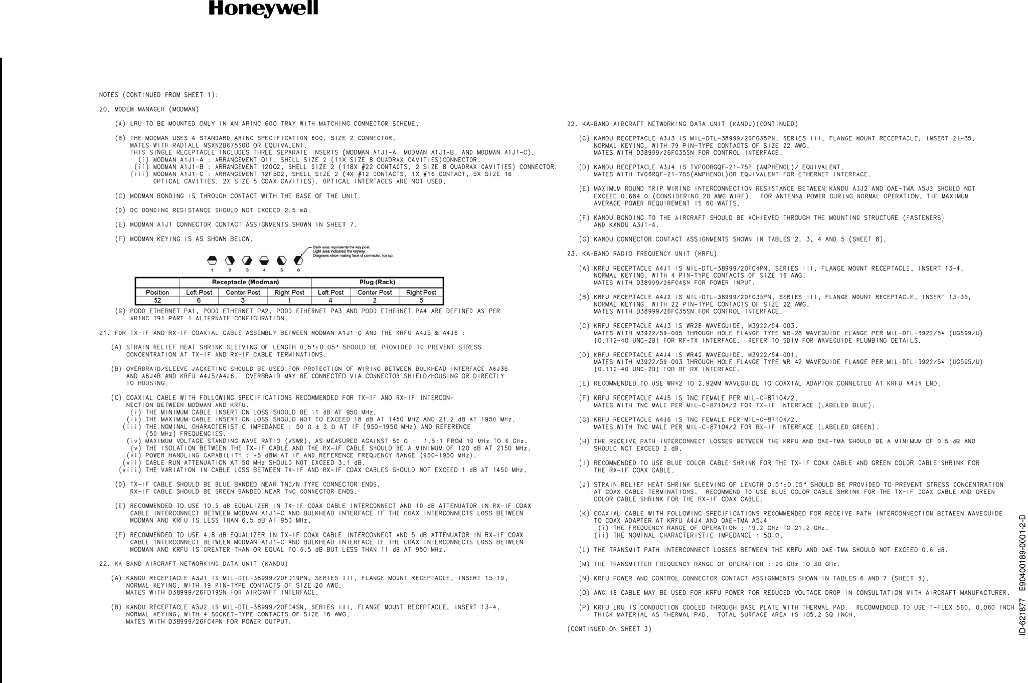
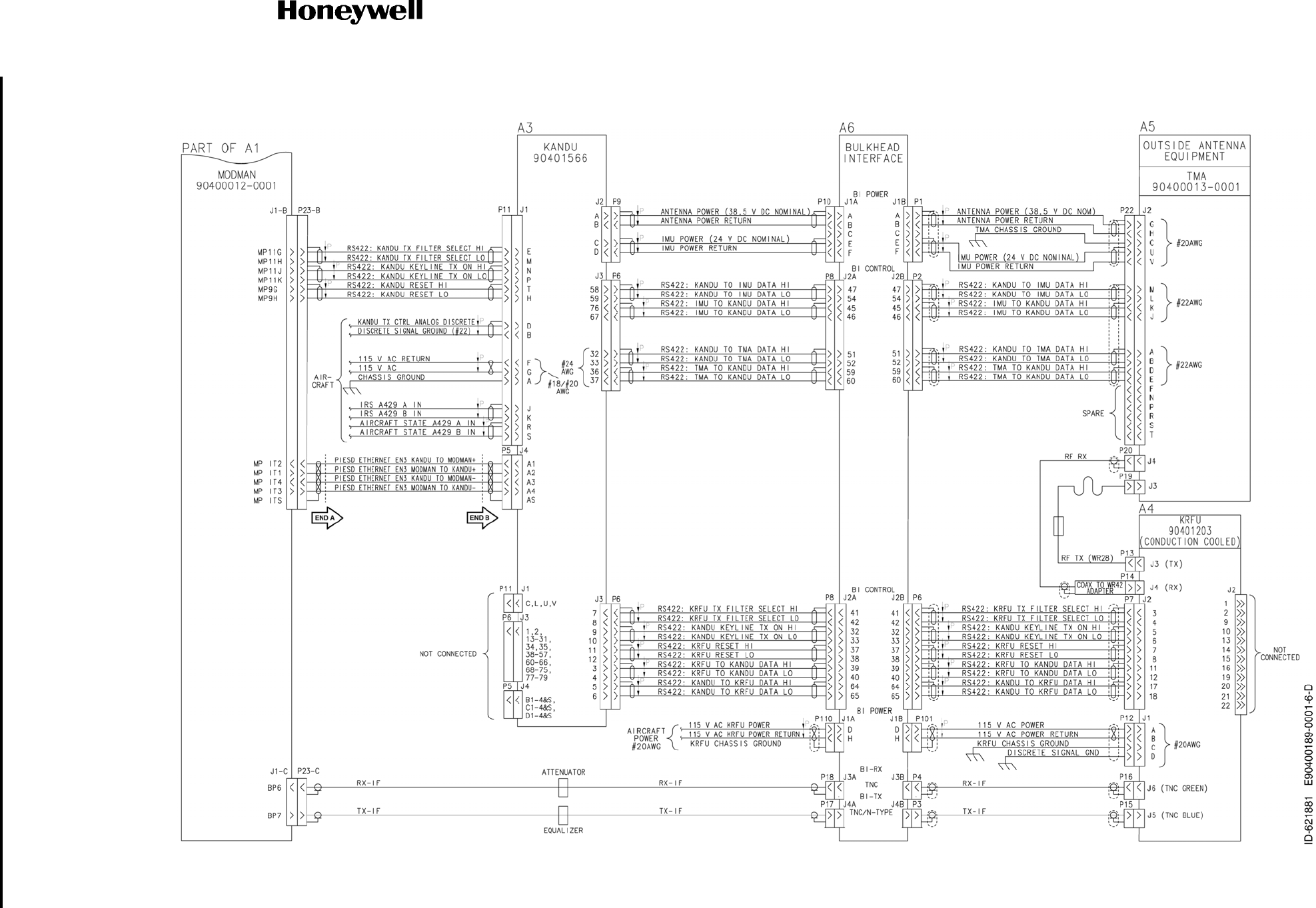
Figure 4-34. (Sheet 2 of 10) JetWave™ System Interconnect Diagram - TMA (90400189-0001, REV D)
Draft as of 31 May 2017
SYSTEM DESCRIPTION AND INSTALLATION MANUAL
JetWave™ System
Page 4-108
3 Mar 2017
© Honeywell International Inc. Do not copy without express permission of Honeywell.
23-15-29
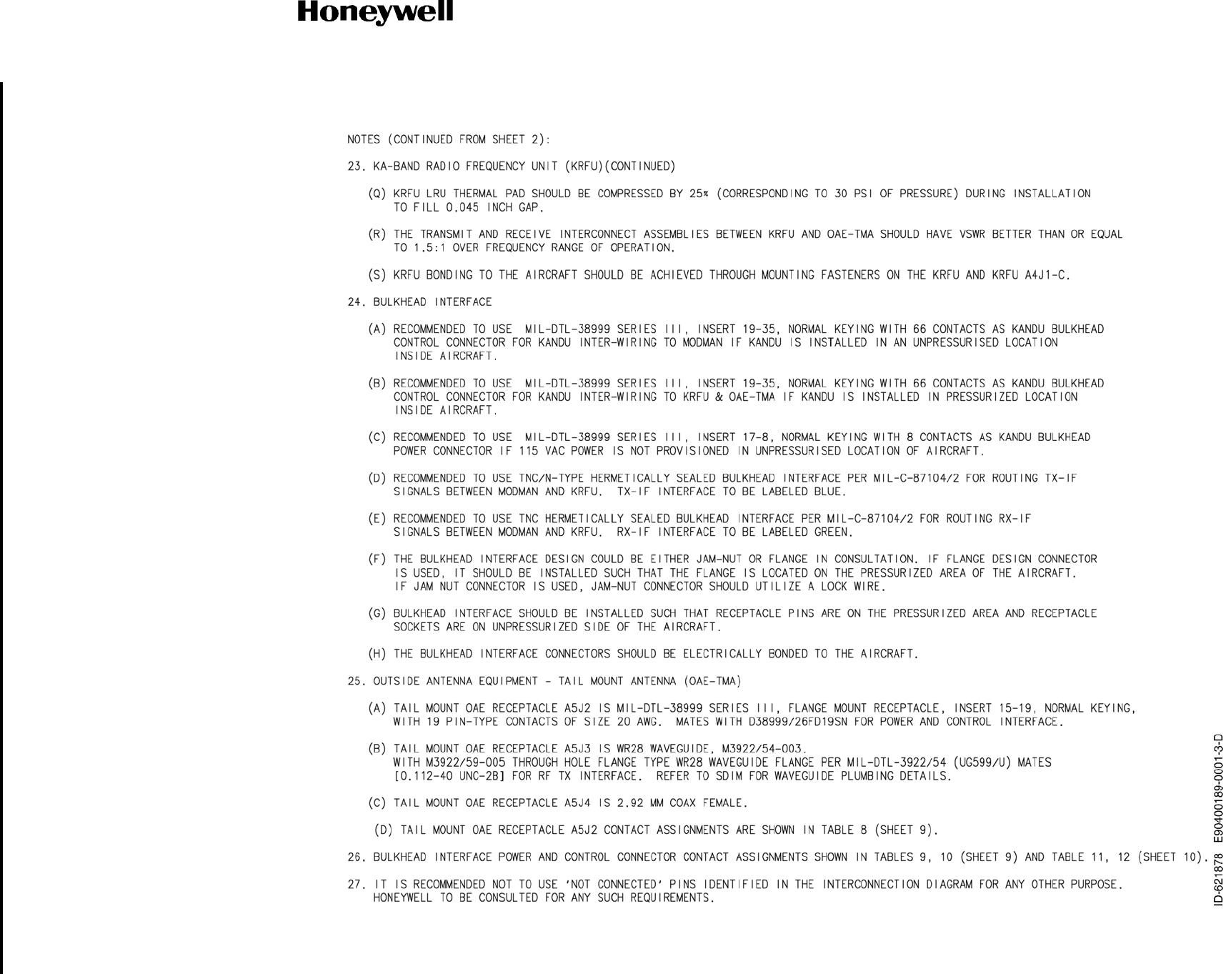
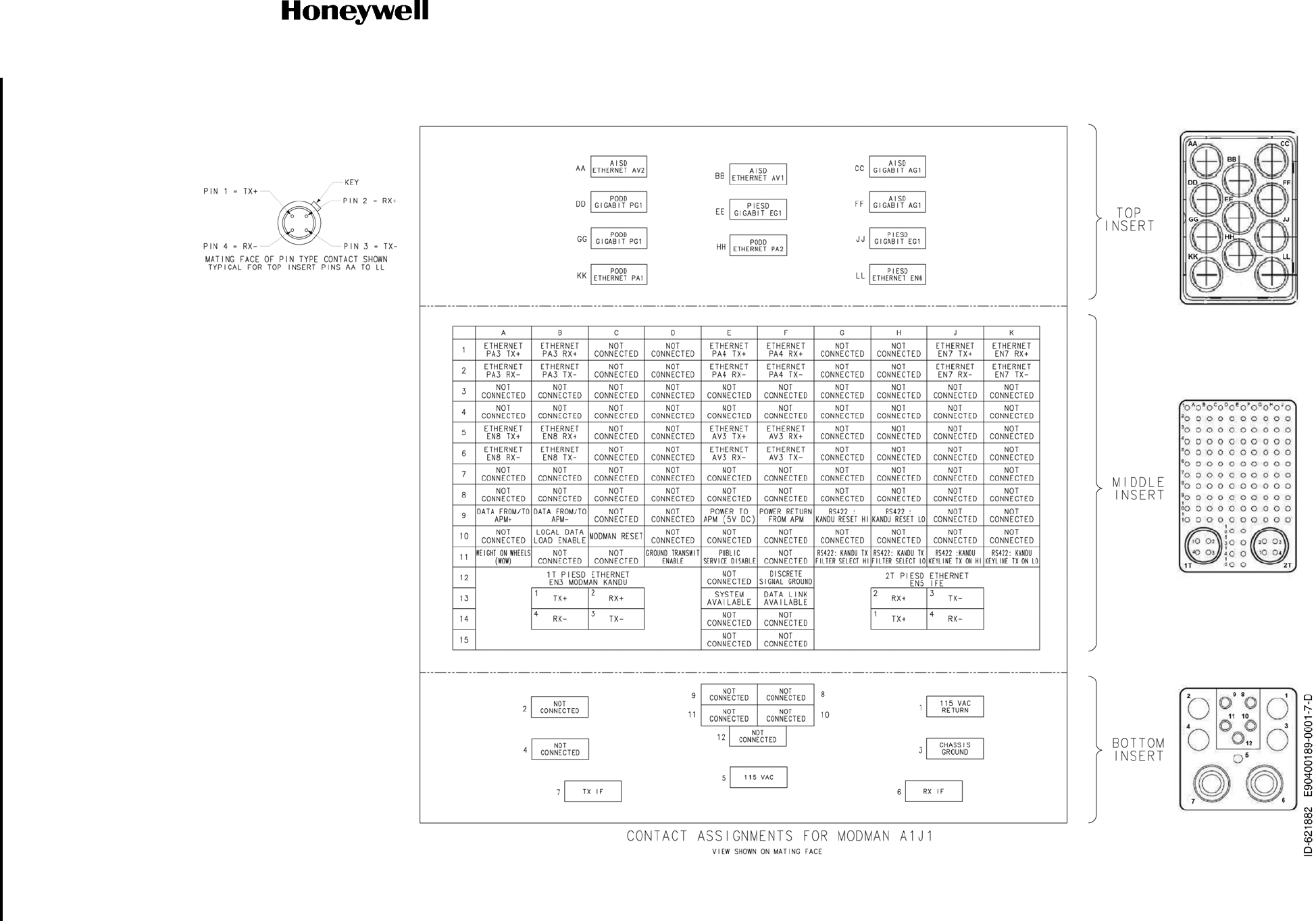
Figure 4-34. (Sheet 3 of 10) JetWave™ System Interconnect Diagram - TMA (90400189-0001, REV D)
Draft as of 31 May 2017
SYSTEM DESCRIPTION AND INSTALLATION MANUAL
JetWave™ System
Page 4-109
3 Mar 2017
© Honeywell International Inc. Do not copy without express permission of Honeywell.
23-15-29
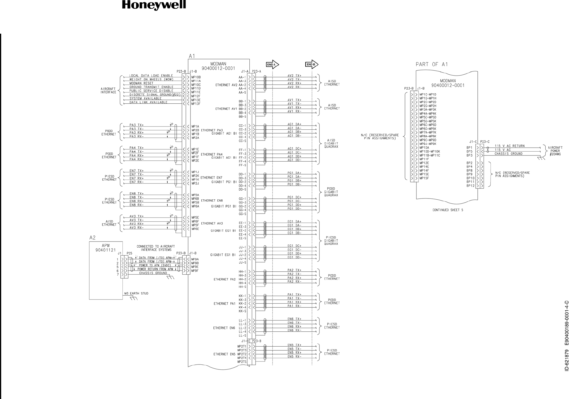
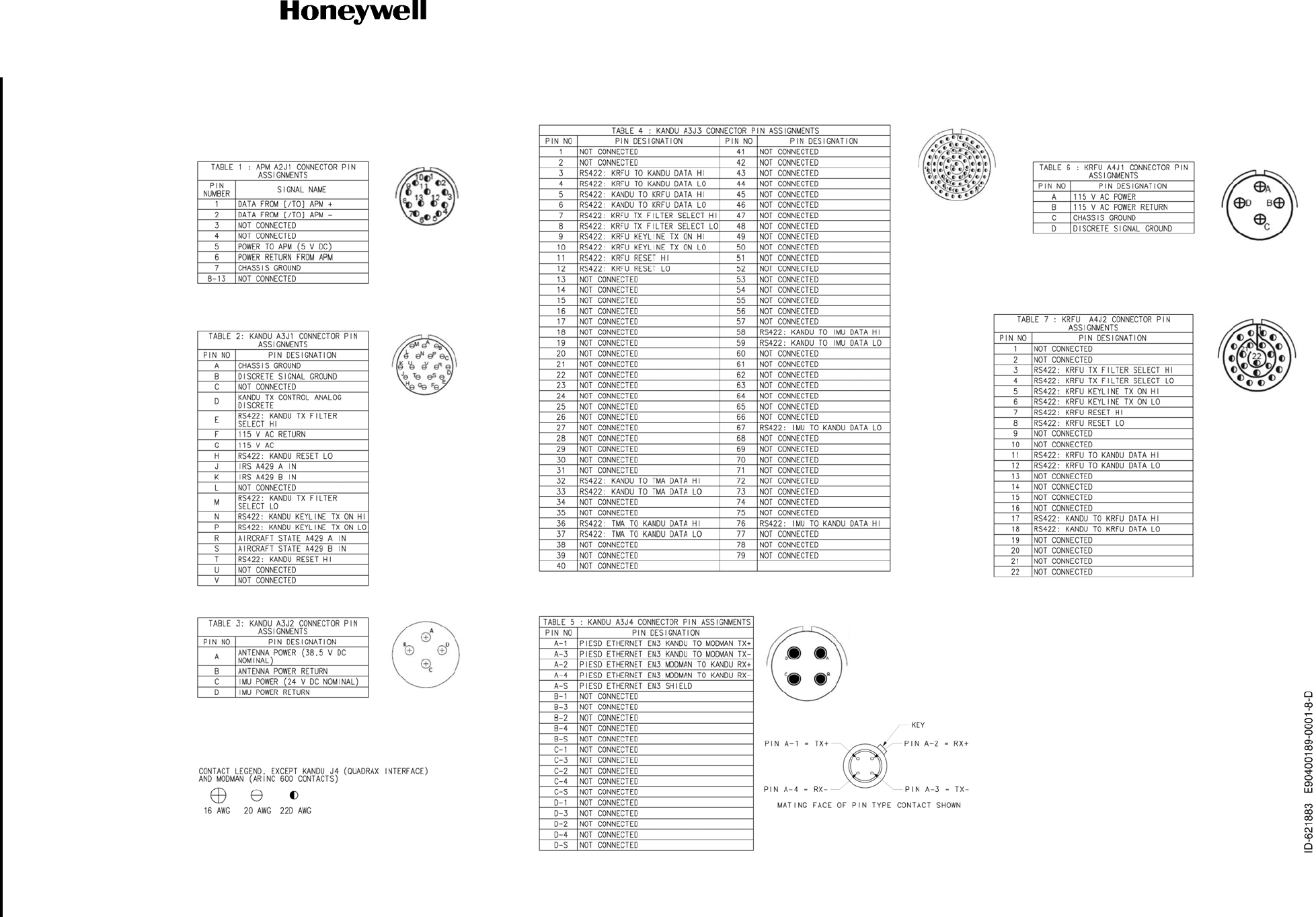
Figure 4-34. (Sheet 4 of 10) JetWave™ System Interconnect Diagram - TMA (90400189-0001, REV D)
Draft as of 31 May 2017
SYSTEM DESCRIPTION AND INSTALLATION MANUAL
JetWave™ System
Page 4-110
3 Mar 2017
© Honeywell International Inc. Do not copy without express permission of Honeywell.
23-15-29
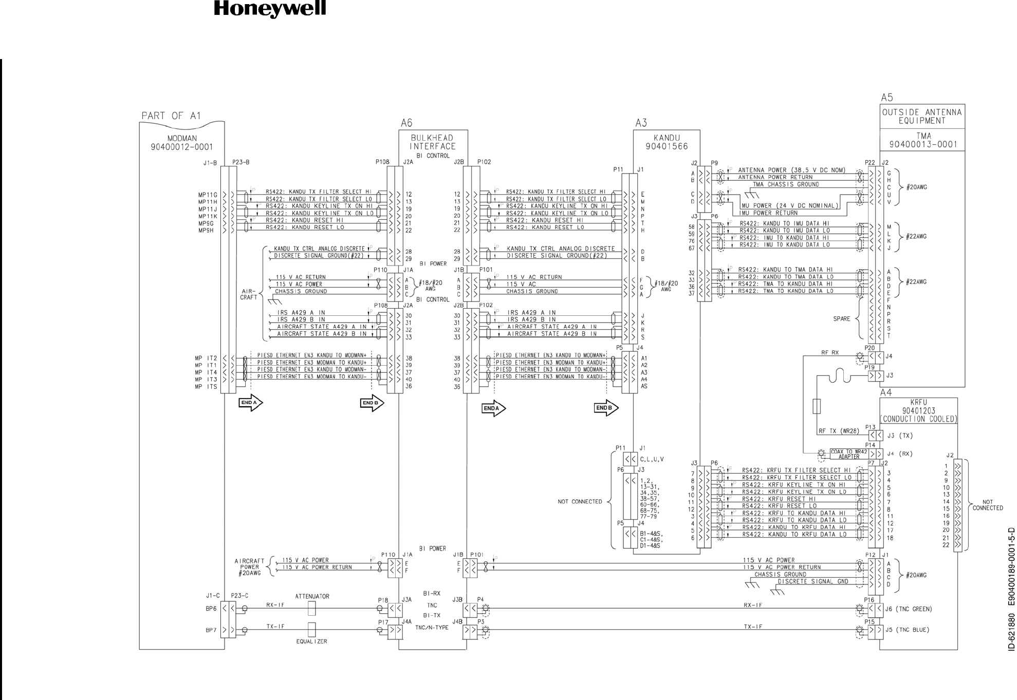
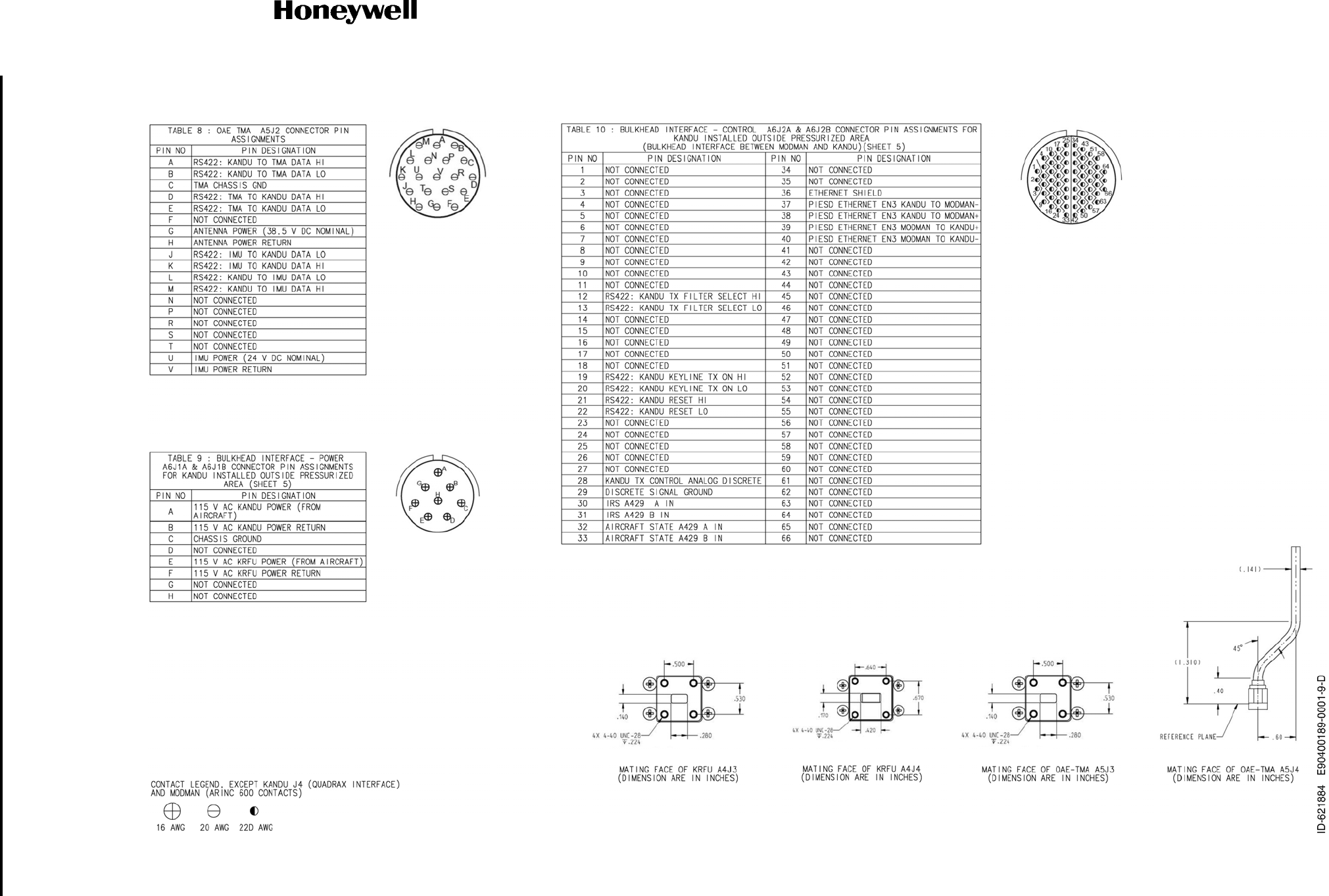
Figure 4-34. (Sheet 5 of 10) JetWave™ System Interconnect Diagram - TMA (90400189-0001, REV D)
Draft as of 31 May 2017
SYSTEM DESCRIPTION AND INSTALLATION MANUAL
JetWave™ System
Page 4-111
3 Mar 2017
© Honeywell International Inc. Do not copy without express permission of Honeywell.
23-15-29
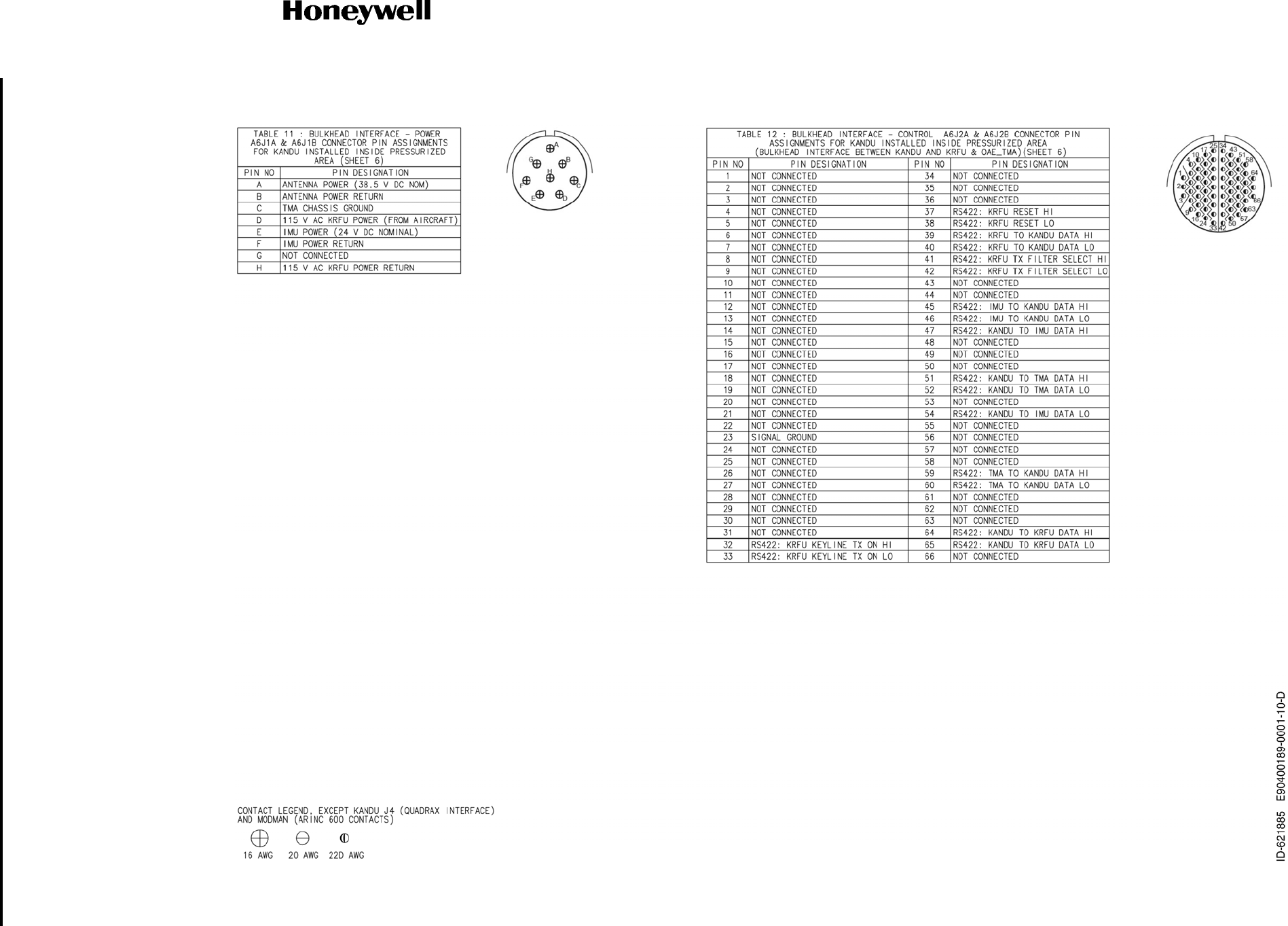
Figure 4-34. (Sheet 6 of 10) JetWave™ System Interconnect Diagram - TMA (90400189-0001, REV D)
Draft as of 31 May 2017
SYSTEM DESCRIPTION AND INSTALLATION MANUAL
JetWave™ System
Page 4-112
3 Mar 2017
© Honeywell International Inc. Do not copy without express permission of Honeywell.
23-15-29
Figure 4-34. (Sheet 7 of 10) JetWave™ System Interconnect Diagram - TMA (90400189-0001, REV D)
Draft as of 31 May 2017
SYSTEM DESCRIPTION AND INSTALLATION MANUAL
JetWave™ System
Page 4-113
3 Mar 2017
© Honeywell International Inc. Do not copy without express permission of Honeywell.
23-15-29
Figure 4-34. (Sheet 8 of 10) JetWave™ System Interconnect Diagram - TMA (90400189-0001, REV D)
Draft as of 31 May 2017
SYSTEM DESCRIPTION AND INSTALLATION MANUAL
JetWave™ System
Page 4-114
3 Mar 2017
© Honeywell International Inc. Do not copy without express permission of Honeywell.
23-15-29
Figure 4-34. (Sheet 9 of 10) JetWave™ System Interconnect Diagram - TMA (90400189-0001, REV D)
Draft as of 31 May 2017
SYSTEM DESCRIPTION AND INSTALLATION MANUAL
JetWave™ System
Page 4-115
3 Mar 2017
© Honeywell International Inc. Do not copy without express permission of Honeywell.
23-15-29
Figure 4-34. (Sheet 10 of 10) JetWave™ System Interconnect Diagram - TMA (90400189-0001, REV D)
Draft as of 31 May 2017
SYSTEM DESCRIPTION AND INSTALLATION MANUAL
JetWave™ System
Page 4-116
3 Mar 2017
© Honeywell International Inc. Do not copy without express permission of Honeywell.
23-15-29
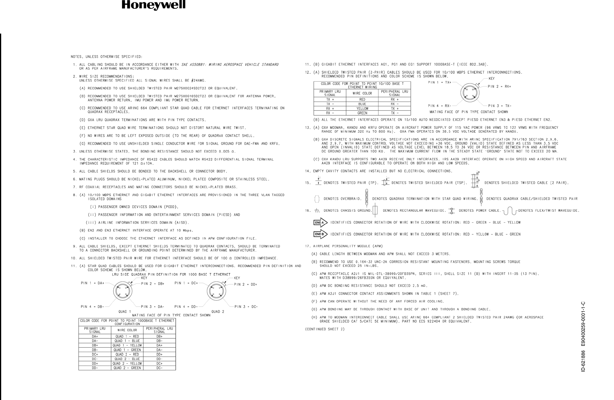
Figure 4-35. (Sheet 1 of 8) JetWave™ System Interconnect Diagram - FMA (KRFU Inside Aircraft Fuselage), (90400259-0001, REV C)
Draft as of 31 May 2017
SYSTEM DESCRIPTION AND INSTALLATION MANUAL
JetWave™ System
Page 4-117
3 Mar 2017
© Honeywell International Inc. Do not copy without express permission of Honeywell.
23-15-29
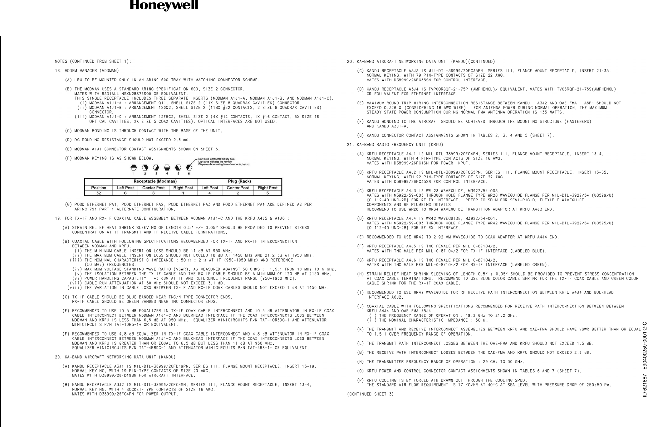
Figure 4-35. (Sheet 2 of 8) JetWave™ System Interconnect Diagram - FMA (KRFU Inside Aircraft Fuselage), (90400259-0001, REV C)
Draft as of 31 May 2017
SYSTEM DESCRIPTION AND INSTALLATION MANUAL
JetWave™ System
Page 4-118
3 Mar 2017
© Honeywell International Inc. Do not copy without express permission of Honeywell.
23-15-29
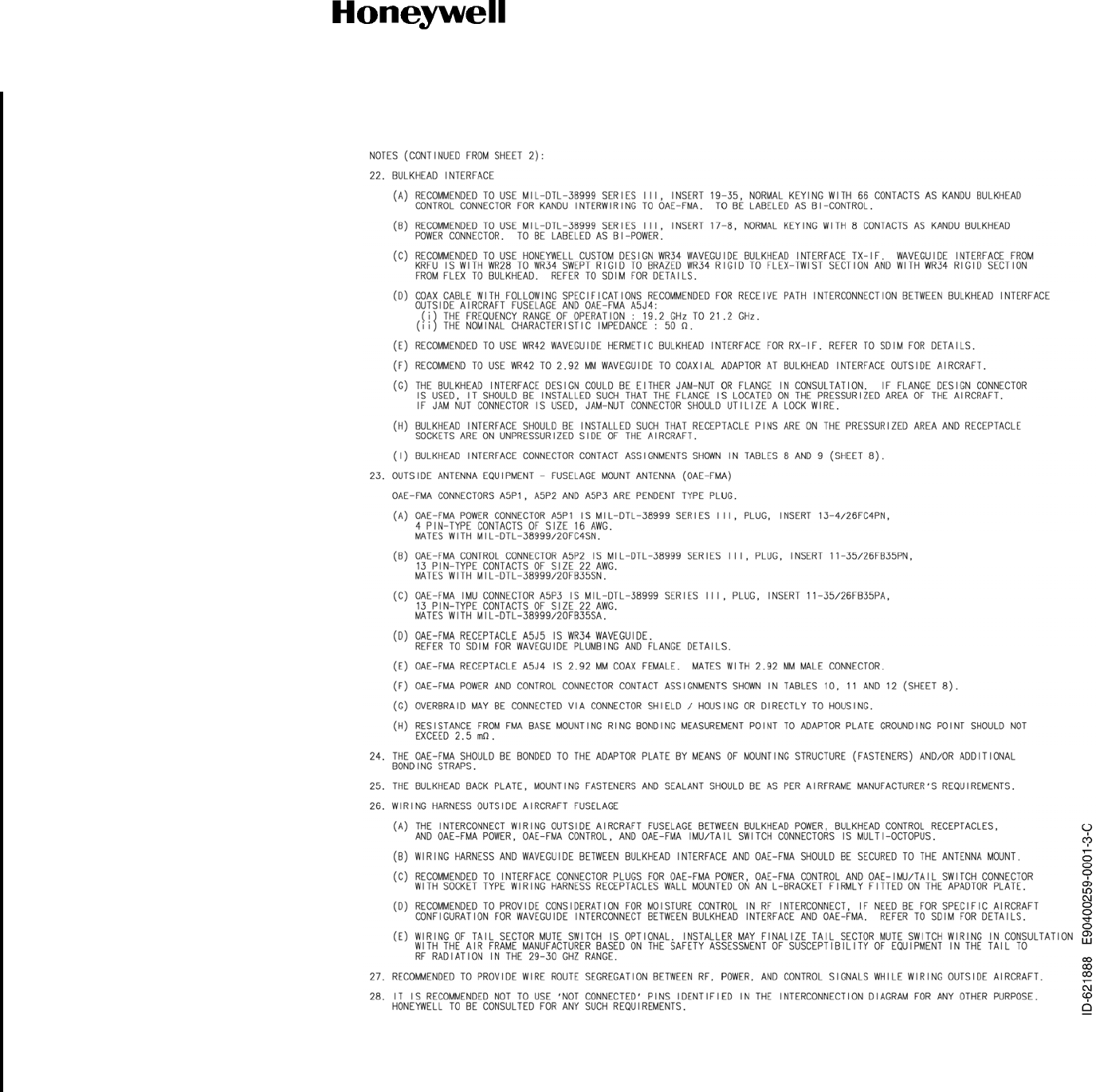
Figure 4-35. (Sheet 3 of 8) JetWave™ System Interconnect Diagram - FMA (KRFU Inside Aircraft Fuselage), (90400259-0001, REV C)
Draft as of 31 May 2017