EMS Technologies Canada JETWAVE2 Jetwave User Manual 23 15 29R004
EMS Technologies Canada, Ltd. Jetwave 23 15 29R004
Contents
User Manual_Part 2
Page 4-32
3 Mar 2017
23-15-29
SYSTEM DESCRIPTION AND INSTALLATION MANUAL
JetWave™ System
© Honeywell International Inc. Do not copy without express permission of Honeywell.
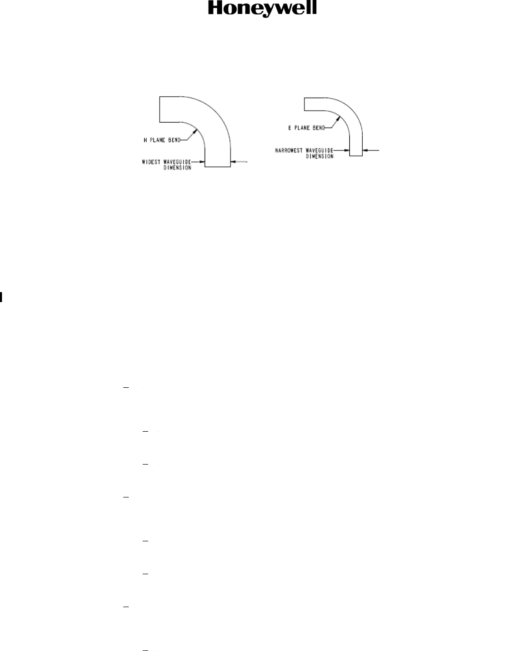
mm) in E plane (bend along the short axis of the waveguide). The minimum allowable
bend radius for the coax cable is 0.25 inch (6.35 mm). Refer to Figure 4-17.
Figure 4-17. View of H Plane and E Plane Bends
(g) Connecting the TMA interface, KRFU Power, and Control Interface
Power and control signals for the TMA assembly are supplied from the KANDU and is
connected to TMA J2 receptacle. Install location of KANDU is airframe specific. KANDU
could be installed in unpressurized area near the tail empennage of the aircraft or inside
pressurized area of the aircraft. In the case where the KANDU is installed inside the
aircraft pressure vessel, the MODMAN to KRFU, the KANDU to KRFU and KANDU to
TMA interconnect may be routed through a Bulkhead Interface connector.
Control signals for the KRFU are supplied from the KANDU and are connected to KRFU
J2 receptacle. 115 VAC power supply for KRFU is supplied from aircraft power and is
connected to KRFU J1 receptacle. IF TX and IF RX signals to KRFU are supplied from
Modman. Refer to the TMA interconnection diagram Figure 4-34 for details.
1Remove the protective covers from the TMA J2 and KANDU J2 receptacles.
Visually inspect connectors and make sure that the pins are straight and not
damaged.
aClean the connectors with contact cleaner and connect the cable assembly for
tail mount from KANDU J2 receptacle to TMA J2 receptacle.
bMake sure that the over braid of the cable assembly is terminated to connectors
at both TMA and KANDU ends.
2Remove the protective covers from the KRFU J2 and KANDU J3 receptacles.
Visually inspect connectors and make sure that the pins are straight and
undamaged.
aClean the connectors with contact cleaner and connect the cable assembly for
tail mount from KANDU J3 receptacle to KRFU J2 receptacle.
bMake sure that the over braid of the cable assembly is terminated to connectors
at both KRFU and KANDU ends.
3Remove the protective covers from the KRFU J5 and KRFU J6 receptacles. Visually
inspect connector ends and make sure that there is no debris in central connector
cavity.
aClean the connectors with the contact cleaner before connecting.
Draft as of 31 May 2017
Page 4-33
3 Mar 2017
23-15-29
SYSTEM DESCRIPTION AND INSTALLATION MANUAL
JetWave™ System
© Honeywell International Inc. Do not copy without express permission of Honeywell.
(1) TX-IF connects from the Modman through the bulkhead J4B to KRFU J5.
(2) RX-IF connects from the Modman through the bulkhead J3B to KRFU J6.
bMake sure that the TX-IF coax cable is banded blue and RX-IF coax cable is
banded green at connector ends.
cMake sure that the over braid of the cable assembly is terminated to connectors
at both KRFU and Modman or the bulkhead interface feed through ends.
dThe over braid can be terminated to connector shield/housing or directly to
housing.
4Make sure that all cable assembly routings are firmly held with wire clamps in
accordance with the airframe specific wiring diagram and that there are no
obstructions to the free movement of tail mount antenna.
On completion of LRU interconnection and applying power to TMA, the tail mount
antenna will move in azimuth and elevation direction and move itself to its home
position.
(h) Radome and Radome Fairing Installation with the TMA Interface Mount
Radome and fairing installation is aircraft specific. See aircraft specific SDIM for details.
NOTE: Before removing the Tail Mount Radome, Honeywell recommends manually
steering the TMA to a safe antenna orientation position using the JetWave™
GUI. The TMA does not power down in a specific "Park" position, as there is
insufficient time on power down to accomplish this. It instead "parks" wherever
it is when power is applied, until the system is ready to operate and the antenna
automatically starts steering towards the satellite.
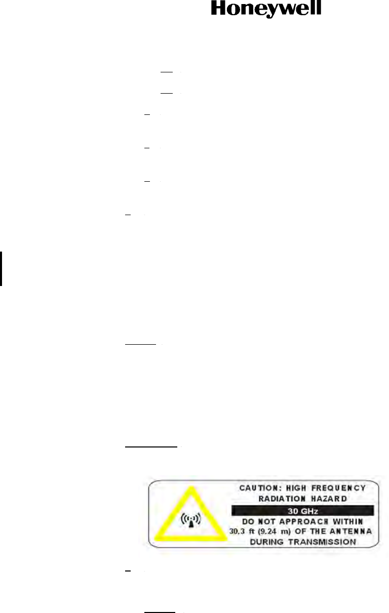
(i) TMA Human Exposure to RF EM Fields
WARNING: THE JETWAVE™ SYSTEM IS A SOURCE OF NON-IONIZING
RADIATION.
1The Minimum Safe Distance:
• TMA = 30.3 feet (9.24 m).
NOTE: The minimum safe distance for occupational/controlled exposure is
determined based on the computational method specified in FCC Office of
Engineering and Technology; Bulletin Number 65, Edition 97-01:
Evaluating compliance with FCC Guidelines for human exposure to Radio
Frequency Electromagnetic fields.
Draft as of 31 May 2017
Page 4-34
3 Mar 2017
23-15-29
SYSTEM DESCRIPTION AND INSTALLATION MANUAL
JetWave™ System
© Honeywell International Inc. Do not copy without express permission of Honeywell.
2The areas which the risk exists are based upon the location of the antenna. This
means personnel operating on the apron, transient personnel, and the general
population in the controlled exposure category will not be exposed to levels in
excess of the limits. Maintenance personnel working close to the tail must be
protected by disabling the transmitter before they approach that area of the aircraft.
3The JetWave™ system incorporates three fail-safe features to limit the potential for
human exposure to non-ionizing radiation:
aThe system will not transmit unless the receiver is receiving a valid signal,
therefore if the received signal were to become blocked the transmitter would be
disabled.
bThe antenna subsystem includes a hardware end-stop that prevents the
antenna pointing more than 2 degrees below the horizontal.
(7) An input into the JetWave™ system wired on the aircraft to a switch in the aircraft, to disable
the RF transmission. This switch would be used to prevent any radiation from the antenna in
the event of aircraft operations in the vicinity of the antenna, for instance when de-icing the
aircraft. This would be achieved by a defined procedure on the aircraft.
4.8 Tail Mount Antenna (If applicable)
A. Introduction
The TMA assembly is intended to be installed on the aircraft tail tip/empennage. For the JetWave™
system to correctly point the antenna, the installation offsets should not exceed more than 1° off
heading, pitch or roll with respect to principal axis of aircraft. Depending on the airframe, the LRUs
and assemblies that follow would be installed outside aircraft fuselage as part of tail mount OAE:
• The TMA assembly
• KRFU LRU
• Radome assembly
• Radome fairing (if required).
• RF interconnect components:
• Tx waveguide
•Rx coax
• Rx coax to waveguide adapter
•O-rings
• waveguide and adapter attachment fasteners
The exact install location of the TMA assembly and KRFU is airframe specific.
The radome, radome fairing (if required), and TMA/KRFU to aircraft interface brackets are airframe
specific; the related details are not covered in this manual.
The following factors must be considered when deciding where to install the antenna:
Draft as of 31 May 2017
Page 4-35
3 Mar 2017
23-15-29
SYSTEM DESCRIPTION AND INSTALLATION MANUAL
JetWave™ System
© Honeywell International Inc. Do not copy without express permission of Honeywell.
• Other antennas or equipment that may block the JetWave™ antenna from being able to see
the satellite
• The JetWave™ antenna blocking other antennas
• Potential interference by the JetWave™ transmitted signal degrading the received signal of
other aircraft RF systems
• Potential interference by other RF systems degrading the received signal of the JetWave™
system.
The TMA complies with form defined in JetWave™ TMA outline and installation drawing in Figure
4-30, the KRFU outline and installation drawing Figure 4-27 thru Figure 4-29, and the interconnect
diagram in Figure 4-34.
Refer to Table 4-8 for special tools, fixtures, and equipment for the TMA installation.
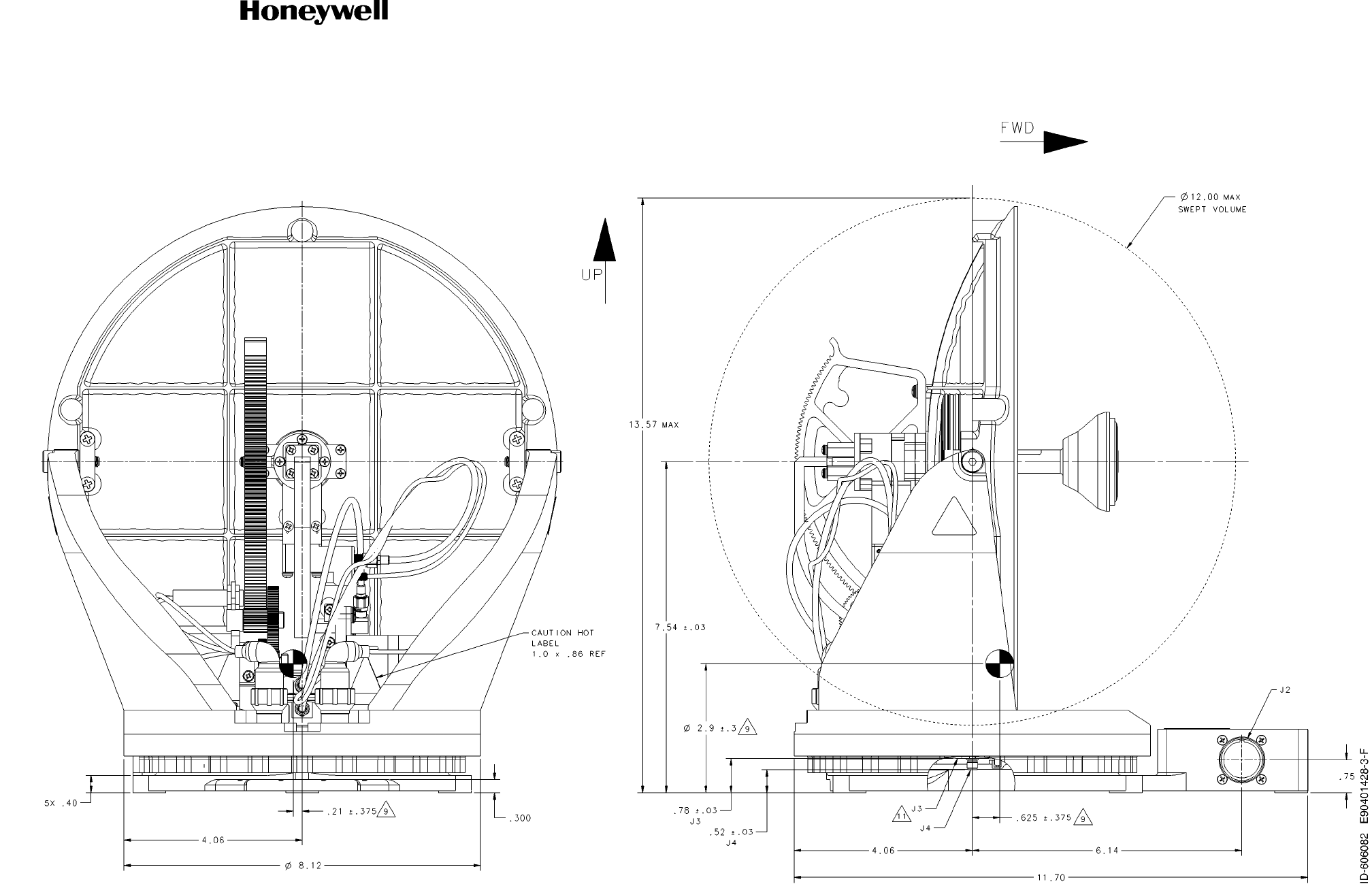
Antenna clearance for swept volume is 12 inches (304.8 mm) minimum around dish sweep
area.
B. TMA Installation General
Before installing any components or cabling, read all notes on drawings and read all installation
procedures.
The installer must select the appropriate gauge of wire as specified in the TMA interconnection
diagram in Figure 4-34 for power and control connections. Interconnect cables must be routed
away from sources of potential electromagnetic interference.
The screws used to attach the waveguide flange to the underside of the TMA must not protrude
more than 0.20 inches (0.508 cm) into the TMA base as indicated in the TMA outline and installation
drawing. Refer to Figure 4-29, Note 15.
C. Advisories
The JetWave™ TMA and the KRFU subsystems include components that radiate RF and
microwave emissions in the band between 29.0 and 30.0 GHz.
All service technicians and operators should be informed of the potential hazards of RF and
microwave radiation. When installing and servicing equipment, exercise the safety precautions that
follow.
WARNING: THIS EQUIPMENT RADIATES HIGH FREQUENCY RADIATION AND POSES A
RADIATION HAZARD. CONSIDERING THE WORST CASE CONDITION OF 100
PERCENT REFLECTION FOR TAIL MOUNT ANTENNA, HONEYWELL DEEMS IT
NECESSARY TO ASSURE OEM FUSELAGE ATTENUATION EXCEEDS 19.48 dB FOR
TAIL MOUNTED ANTENNAS SYSTEM INSTALLATION. THIS IS THE MINIMUM
ATTENUATION REQUIRED FROM THE AIRCRAFT FUSELAGE TO ATTENUATE THE
Table 4-8. Special Tools for TMA Installation
Number Description Source
NA Hoist system Commercially available
Draft as of 31 May 2017

Page 4-36
3 Mar 2017
23-15-29
SYSTEM DESCRIPTION AND INSTALLATION MANUAL
JetWave™ System
© Honeywell International Inc. Do not copy without express permission of Honeywell.
KA BAND RADIATION TO MEET A SAFE HUMAN EXPOSURE OF 1 MW/CM2 INSIDE
THE AIRCRAFT.
WARNING: SERVICE TECHNICIANS AND OPERATORS MUST EXERCISE CARE TO KEEP
CLEAR OF THE ANTENNA’S BEAM WHILE PERFORMING OPERATIONAL TESTS OR
INSTALLATION VERIFICATION PROCEDURES. DO NOT APPROACH WITHIN 30.3
FEET (9.24 METERS) OF THE TAIL MOUNT ANTENNA ASSEMBLY DURING RADIO
FREQUENCY TRANSMISSION
WARNING: DURING ANTENNA OPERATION (TRANSMISSION), ENSURE MINIMUM EXPOSURE
OF ALL PERSONNEL TO ANY REFLECTED, SCATTERED, OR DIRECT BEAMS.
WARNING: SERVICE TECHNICIANS MUST OBEY STANDARD SAFETY PRECAUTIONS, SUCH
AS WEARING SAFETY GLASSES, TO PREVENT PERSONAL INJURY WHILE
INSTALLING OR PERFORMING SERVICE ON THIS UNIT.
D. TMA Unpacking and Inspection
This section describes how to make sure that the equipment is in good condition after shipping. To
unpack and inspect the equipment, do as follows:
(1) Unpack the equipment components from the shipping container.
(2) Make sure that all the components of the tail mount OAE subsystem as indicated on the parts
list/bill of materials are included.
(3) Visually inspect the units for any shipping damage.
NOTE: Refer to Section 4.10 Inspection of Waveguide.
E. TMA Installation Kit Details
Other than the common components specified in Figure 4-15, the installation kit for waveguide and
coax assemblies, wiring assemblies, brackets, clamps and mounting assembly will be airframe
specific. Refer to airframe specific wiring diagram for details.
Table 4-9. TMA RF Interconnect Common Installation Components
PN Description
SCD-90402677 WR42 to 2.92 mm coax adapter
MS29513-013 O-ring
MS29513-016 O-ring
90403559 Screw, waveguide and adapter mating flange attachment
MS51957-27 Screw, waveguide flange to TMA
NAS620C6 Washer, waveguide flange to TMA
Draft as of 31 May 2017
Page 4-37
3 Mar 2017
23-15-29
SYSTEM DESCRIPTION AND INSTALLATION MANUAL
JetWave™ System
© Honeywell International Inc. Do not copy without express permission of Honeywell.
CAUTION: THE TAIL MOUNT OAE ASSEMBLY IS ELECTROSTATIC-SENSITIVE. STANDARD
ELECTROSTATIC-SENSITIVE HANDLING PROCEDURES MUST BE OBSERVED.
F. TMA Airframe Structural Modifications
For the installation of TMA, structural modifications to the tail empennage of the airframe may be
required to accommodate the additional mass of the antenna assembly and aerodynamic loads.
The aerodynamic loads are dependent on the aircraft type and corresponding tail tip radome and
lower fairing design/shape. Inertial and thermal loads also need to be accounted for. The installation
location of the TMA and KRFU on the aircraft are installation specific and should be accounted for
on any structural analysis that is carried out.
The appropriately qualified personnel should derive the loads and perform a structural analysis to
verify the suitability of the modifications.
The installer is responsible for all structural modifications to the aircraft.
G. TMA Mounting Guidelines
This section describes the mounting guidelines for the tail mount OAE.
The radome installation is aircraft specific.
The airframe manufacturer can be consulted to determine the torque requirements for mounting the
TMA assembly, KRFU, radome, and radome fairing for each unique installation.
H. TMA Physical Placement
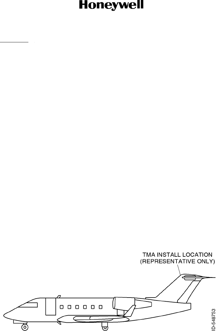
The TMA and KRFU must be mounted on the top of the tail empennage for clear satellite
communications. Figure 4-18 shows a typical installation location for the tail mount antenna
assembly on an aircraft.
Figure 4-18. TMA Installation Location
I. TMA Interface Mount Brackets (if required)
Depending on the airframe, there may be a need to install a TMA to an airframe interface mount
bracket, which adapts to the tail tip structure of the aircraft and in turn supplies a suitable installation
base for the TMA assembly.
Draft as of 31 May 2017
Page 4-38
3 Mar 2017
23-15-29
SYSTEM DESCRIPTION AND INSTALLATION MANUAL
JetWave™ System
© Honeywell International Inc. Do not copy without express permission of Honeywell.
This is not detailed in this document as the requirement of antenna interface mount is air frame
specific.
J. TMA Radome and Radome Fairing
Depending on the airframe, there may be a need to install radome fairing which adapts to the tail
empennage of the aircraft.
This is not detailed in this document as the requirement of radome fairing is airframe specific.
K. TMA Assembly
The tail mount OAE assembly is typically mounted in the same location as the Ku SATCOM radio
slot on the top of the aircraft tail/empennage.
Consult the airframe manufacturer for identification of appropriate airframe specific installation slots
on the empennage.
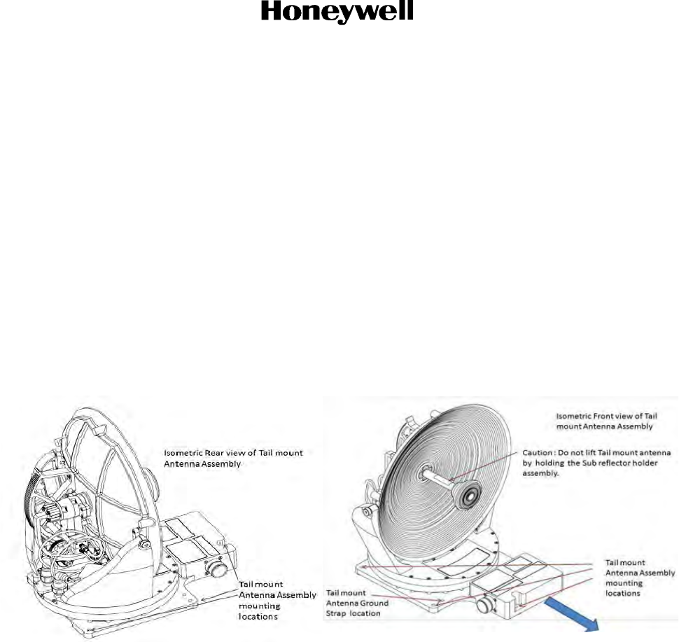
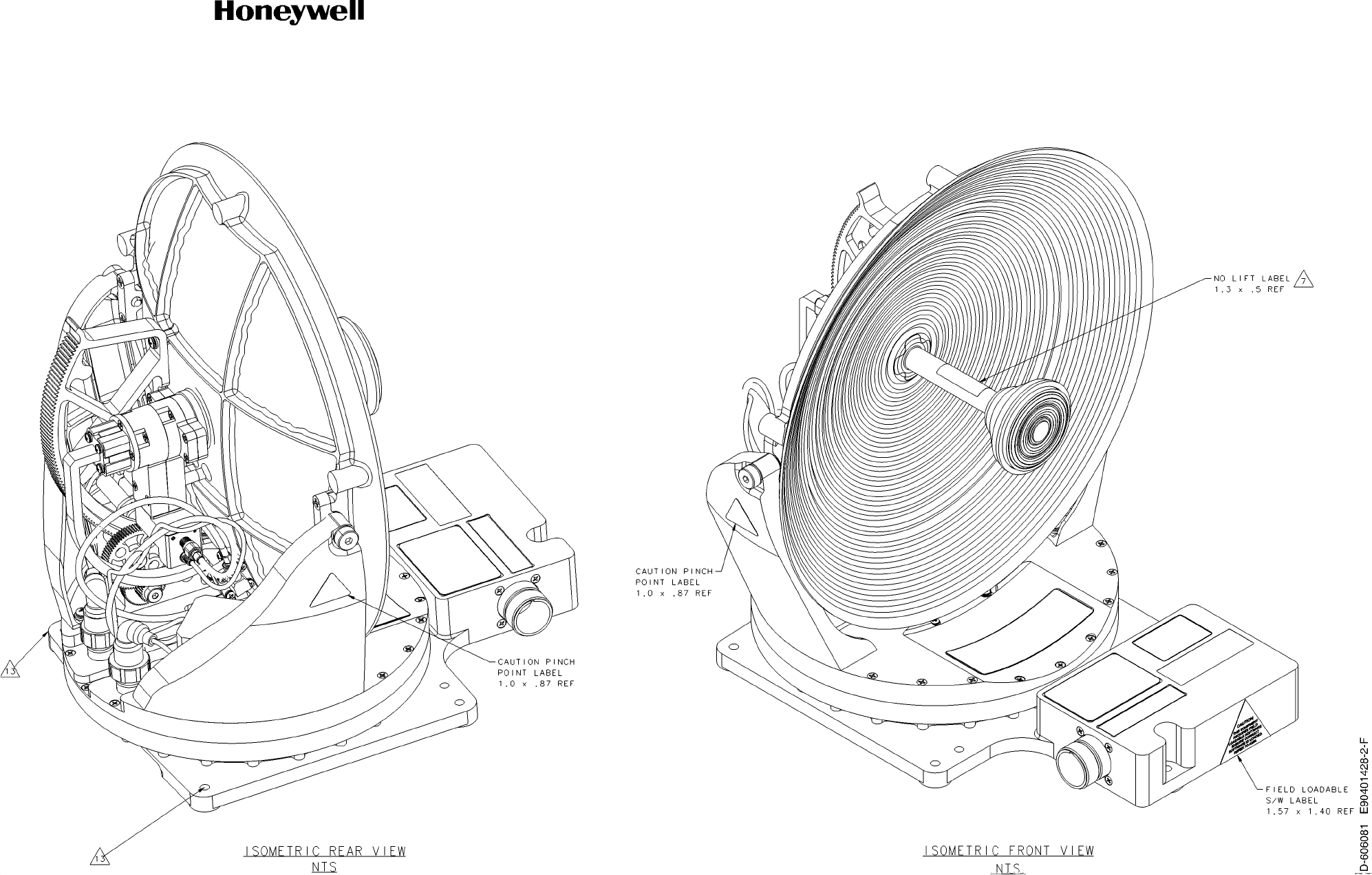
The isometric rear and front views of the TMA assembly is shown in Figure 4-19.
Figure 4-19. TMA Assembly Isometric View
The TMA assembly attaches to the base in five (05) locations. Refer to Figure 4-19 and Figure 4-30
for details.
L. TMA Assembly Orientation
Orientation of the TMA assembly is defined with respect to the principal axes of the aircraft. The
TMA assembly is to be installed such that the TMA J2 connector side is located towards the front
of aircraft as indicated by the arrow as shown in Figure 4-19.
4.9 Radome
The radome installation is aircraft specific. See aircraft specific SDIM for details.
Depending on the AIM selected, the radome gets installed differently.
With the A791 based AIM, the Radome will be installed on the A791 based AIM.
Draft as of 31 May 2017
Page 4-39
3 Mar 2017
23-15-29
SYSTEM DESCRIPTION AND INSTALLATION MANUAL
JetWave™ System
© Honeywell International Inc. Do not copy without express permission of Honeywell.
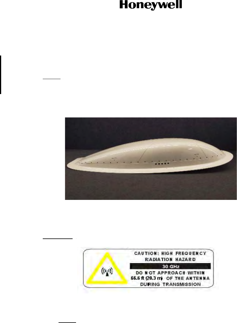
With the LAIM, the radome will be installed on the Radome skirt fairing assembly. Refer to Figure
4-20.
Electrical bonding from the Jetwave™ radome lightning diverters into the airframe must be less
than 25 milliohms.
NOTE: The segmented diverter strips on Jetwave™ radomes do not have electrical continuity
between the segments (buttons). Bonding measurements must be made at the diverter
termination points on the radome (at the radome attachment fastener).
Figure 4-20. Radome Assembly Mounted on Radome Skirt Fairing (LAIM)
A. FMA Human Exposure to RF EM Fields
WARNING: THE JETWAVE™ SYSTEM IS A SOURCE OF NON-IONIZING RADIATION.
(1) The Minimum Safe Distance:
• FMA = 66.6 feet (20.3 m).
NOTE: The minimum safe distance for occupational/controlled exposure is determined
based on the computational method specified in FCC Office of Engineering and
Technology; Bulletin Number 65, Edition 97-01: Evaluating compliance with FCC
Guidelines for human exposure to Radio Frequency Electromagnetic fields.
(2) The areas which the risk exists are based upon the location of the antenna. This means
personnel operating on the apron, transient personnel, and the general population in the
controlled exposure category will not be exposed to levels in excess of the limits.
Maintenance personnel working close to the tail must be protected by disabling the
transmitter before they approach that area of the aircraft.
Draft as of 31 May 2017

Page 4-40
3 Mar 2017
23-15-29
SYSTEM DESCRIPTION AND INSTALLATION MANUAL
JetWave™ System
© Honeywell International Inc. Do not copy without express permission of Honeywell.
(3) The JetWave™ system incorporates three fail-safe features to limit the potential for human
exposure to non-ionizing radiation:
(a) The system will not transmit unless the receiver is receiving a valid signal, therefore if
the received signal were to become blocked the transmitter would be disabled.
(b) The antenna subsystem includes a hardware end-stop that prevents the antenna from
pointing more than 2° below its mounting plane.
(c) An input into the JetWave™ system wired on the aircraft to a switch in the aircraft, to
disable the RF transmission. This switch would be used to prevent any radiation from
the antenna in the event of aircraft operations in the vicinity of the antenna, for instance
when de-icing the aircraft. This would be achieved by a defined procedure on the
aircraft.
4.10 Inspection of Waveguide
Any waveguide received that contains more than one dent is unacceptable and must be returned to the
vendor. Dents must not exhibit obvious signs of mechanical rework such as file marks or rough edges,
where it is obvious that small tools have damaged what should be a precisely machined waveguide.
The very outer edge of the waveguide does not generally contain critical portions of the waveguide
structure that affect performance. Therefore the outer edge of the waveguide may include small dents,
marks, machine tool marks, etc so long as the damage does not structurally impair the waveguide. The
outer surface may contain bending, tool marks or handling damage. A new waveguide that contains large
numbers of dents or marks such that it appears not to be a new article shall be rejected and returned to
the vendor. If more than 25% of the waveguide surface is marred in any way , the antenna must be
rejected and returned to the vendor for rework.
Any evidence of nicks, surface pits, surface etching or scratches on the waveguide are acceptable as long
as the flaw has been caused by the manufacturing process, i.e. brazing, cleaning, honing, a tool and no
larger than 0.030 inch etc. The number or shape of the nicks, pits or scratches are not limited unless
greater than 25% of the waveguide appears to have sustained overall damage of one or more types. Any
waveguide having more than 25% of the surface damaged in this way is not acceptable and must be
returned to the vendor.
The surface finish of the waveguide must not exceed 125 micro inch finish. All measurements will be
made in an area free of braze material. The surface finish will not pertain to any area where excess braze
material has flowed on the back of the waveguide.
4.11 Cabling and Drawings
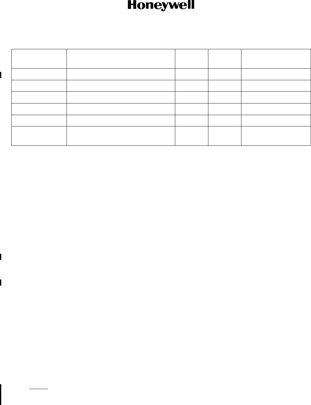
Refer to Table 4-10 for the cabling requirements.
Draft as of 31 May 2017
Page 4-41
3 Mar 2017
23-15-29
SYSTEM DESCRIPTION AND INSTALLATION MANUAL
JetWave™ System
© Honeywell International Inc. Do not copy without express permission of Honeywell.
When installing the JetWave™ system, follow the cabling requirements listed below:
• Ethernet LAN/WAN cables must meet flammability and TIA/EIA568-A CAT 5E requirements.
• Carlisle IT (ECS) 422404 or NF24Q100-01 is recommended for Quadrax connections.
• Twisted shielded pairs must meet ARINC 791 wiring requirements or equivalent.
Refer to Figure 4-34, thru Figure 4-37 for wire size recommendations.
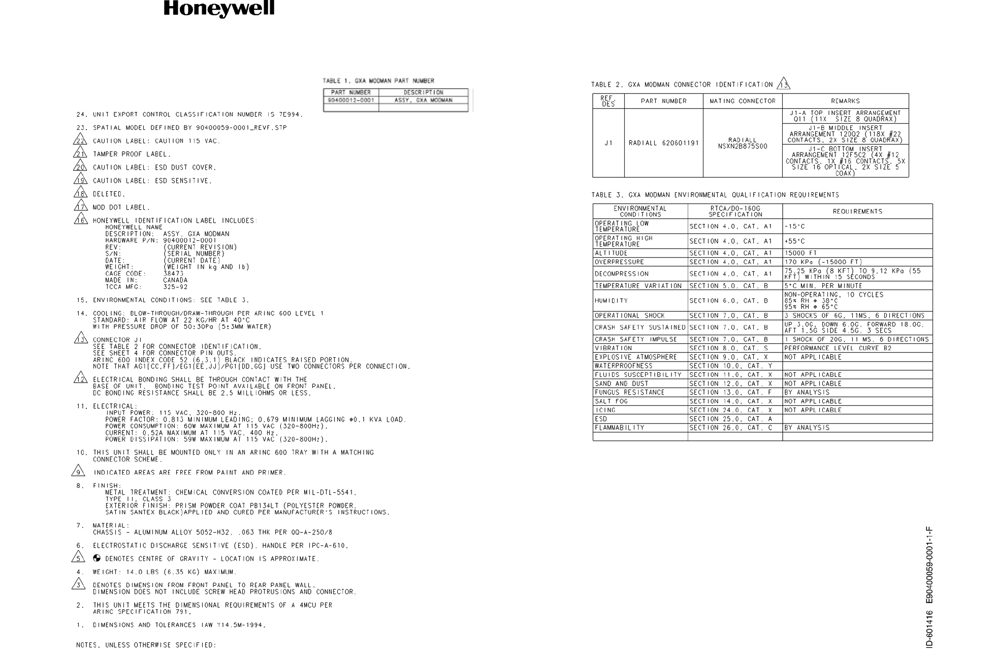
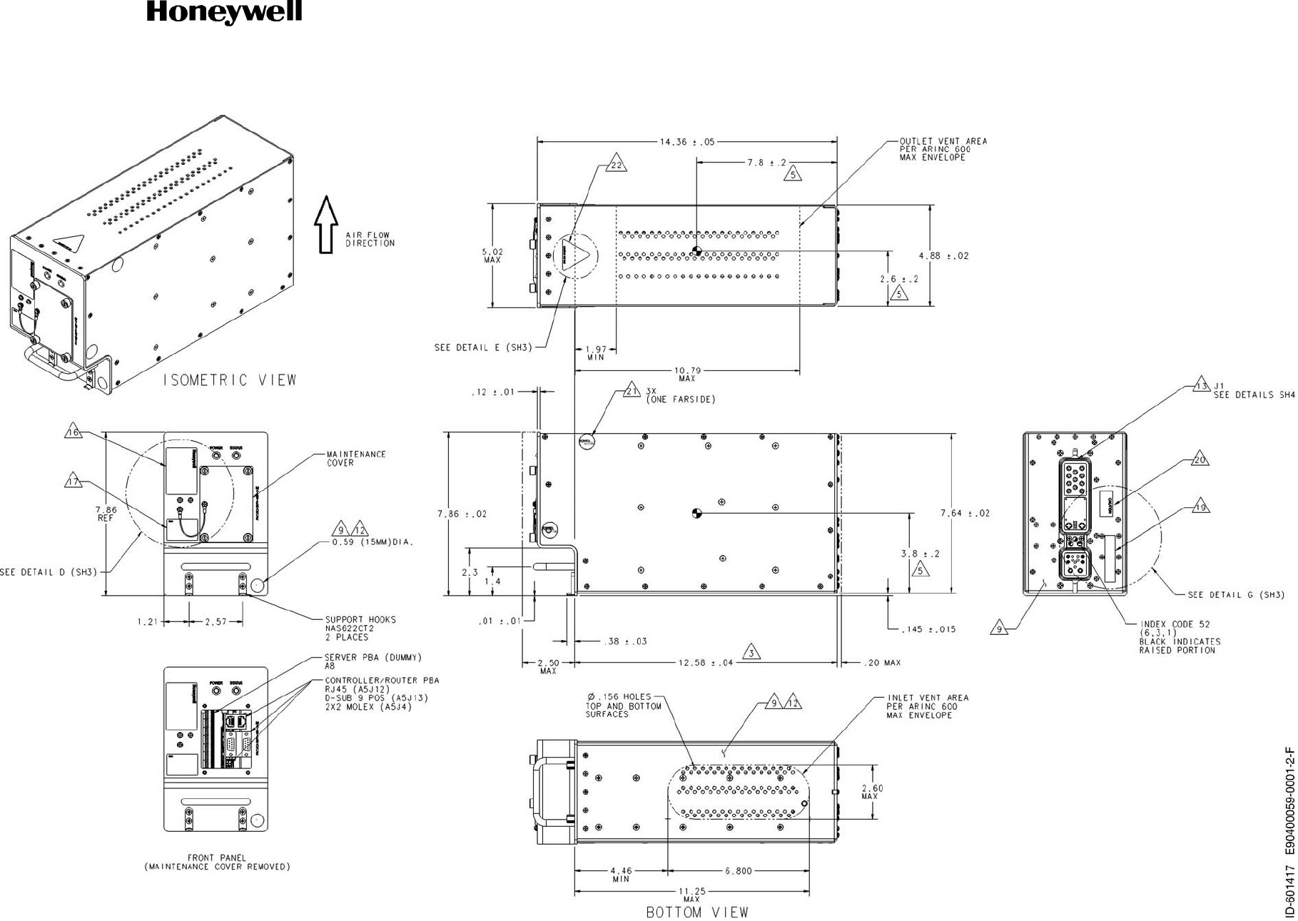
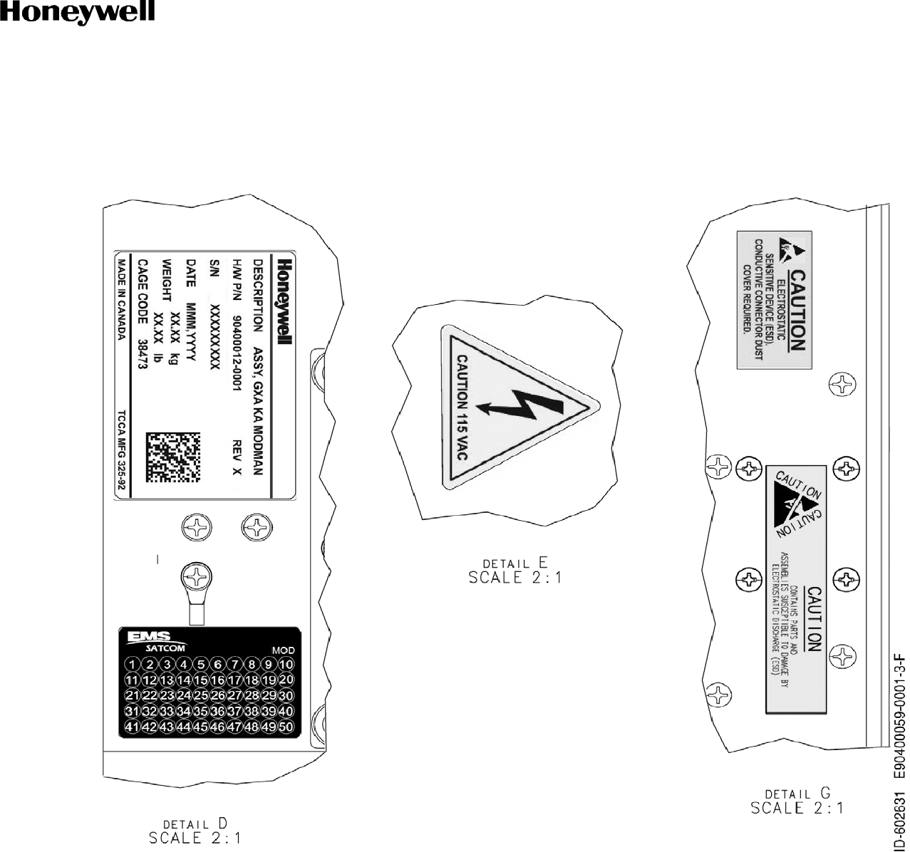
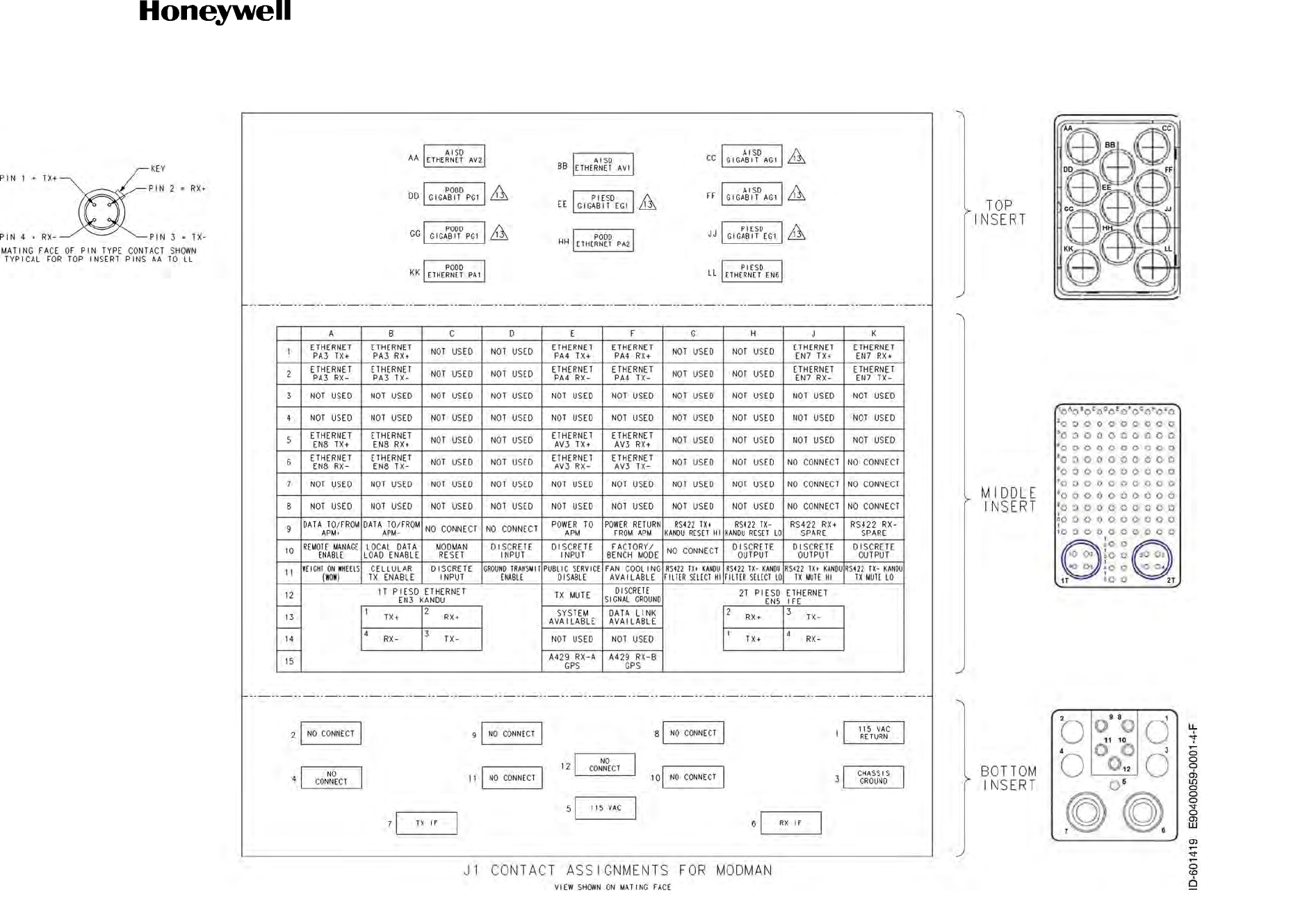
Refer to Figure 4-21 for the Modman (PN 90400059-0001) outline and installation drawing.
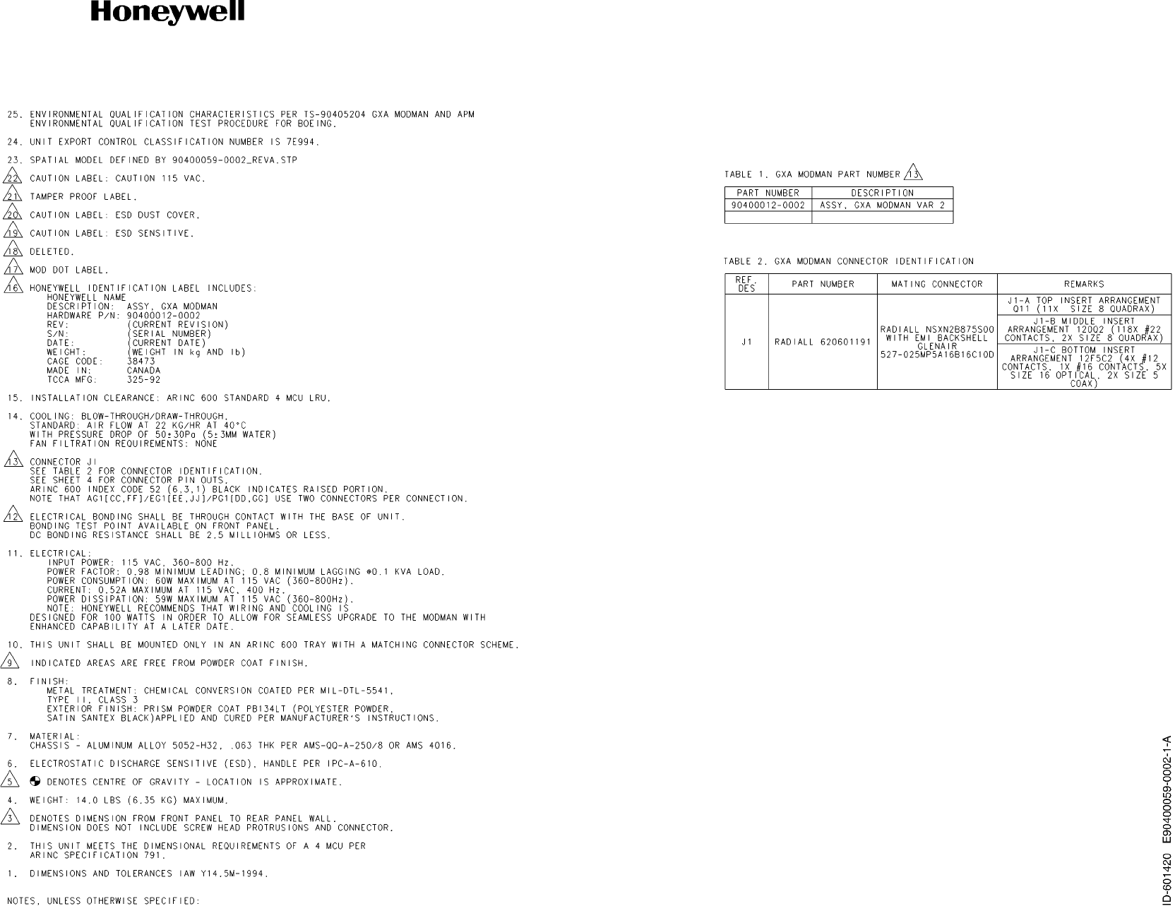
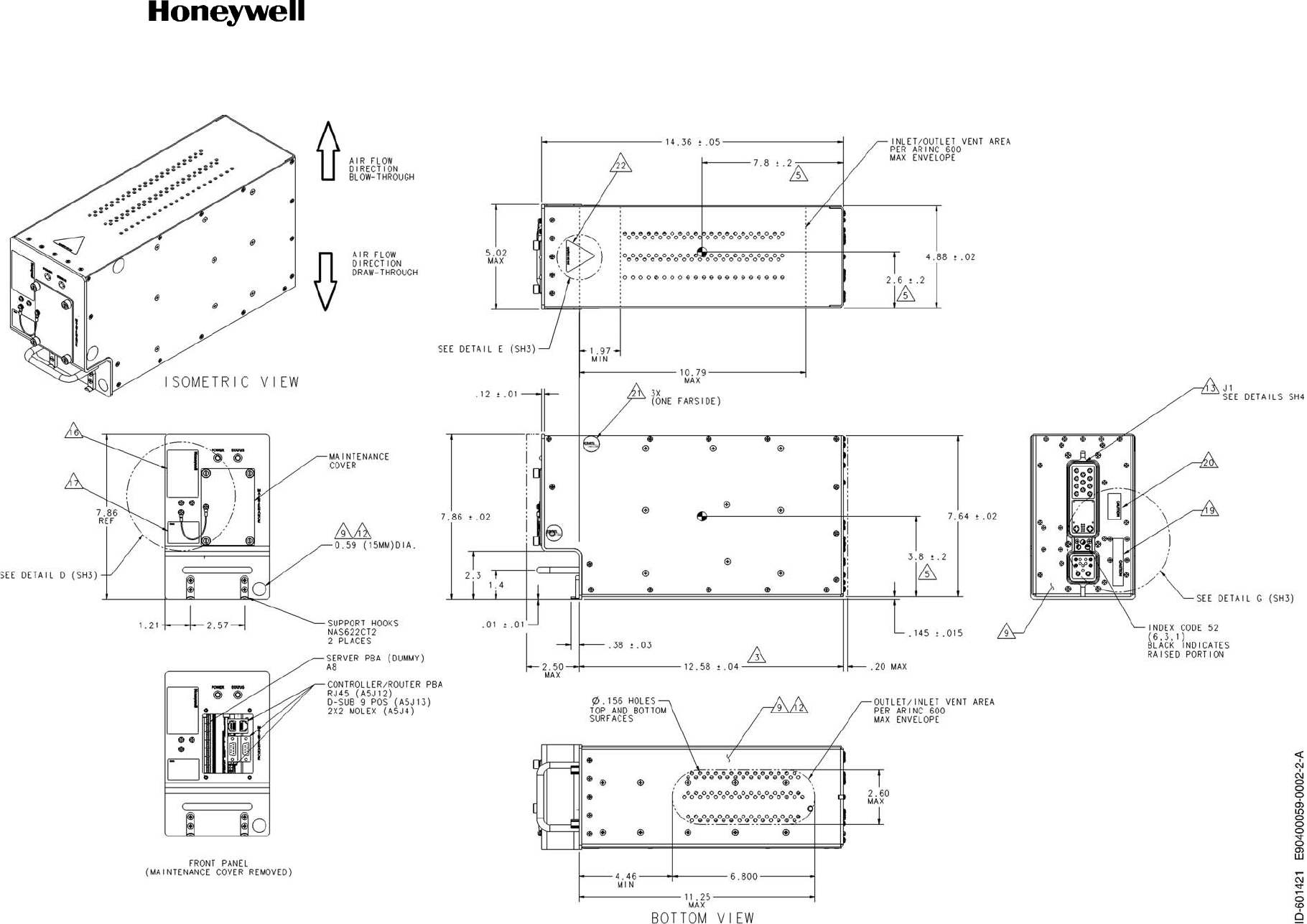
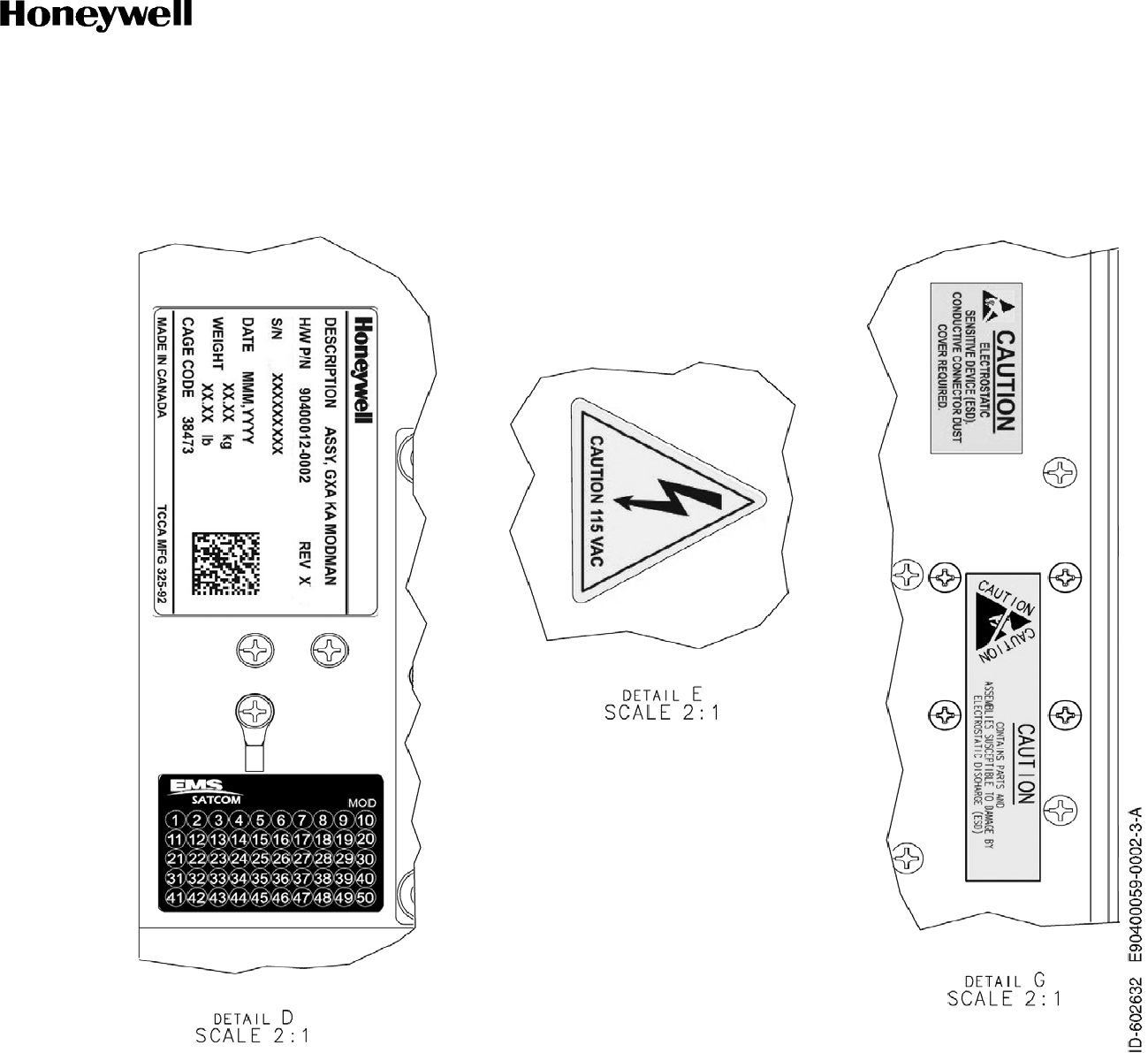
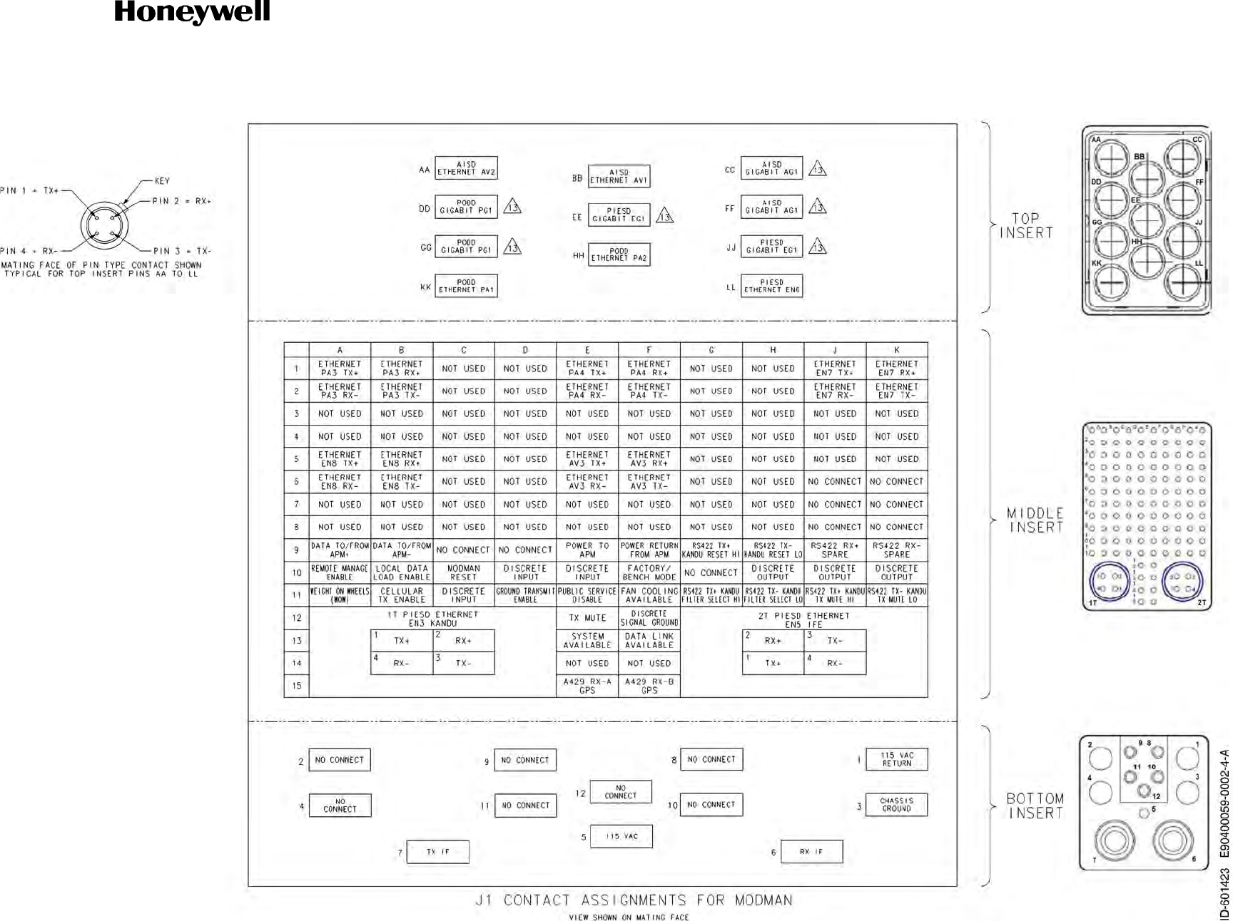
Refer to Figure 4-22 for the Modman Variant 2 (PN 90400059-0002) outline and installation drawing.
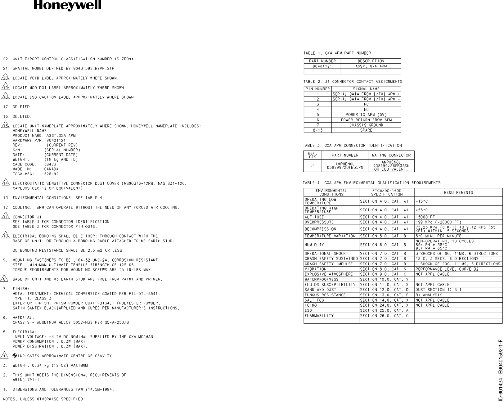
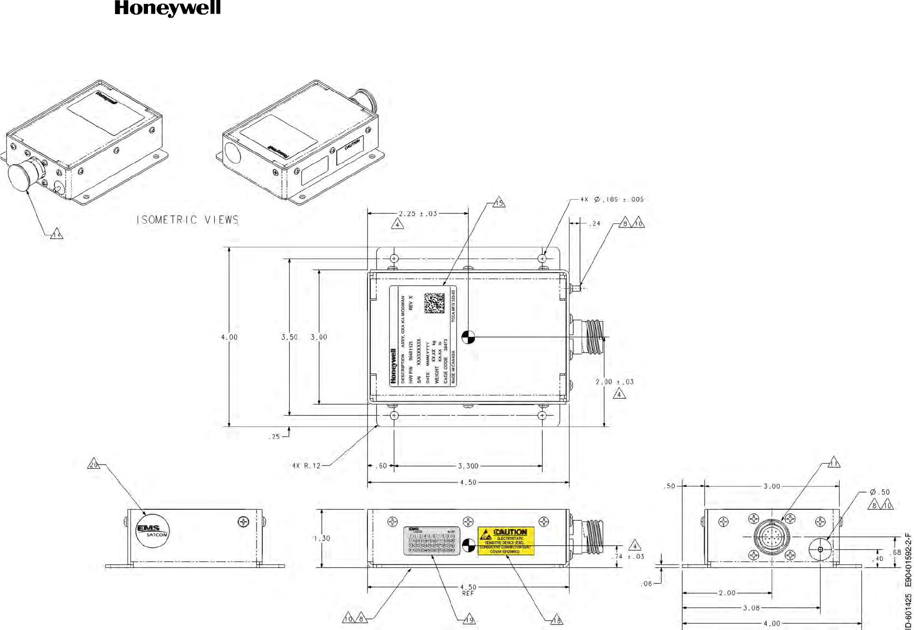
Refer to Figure 4-23 for the APM (PN 90401592) outline and installation drawing.
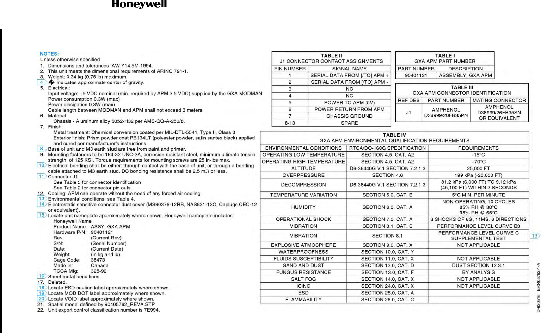
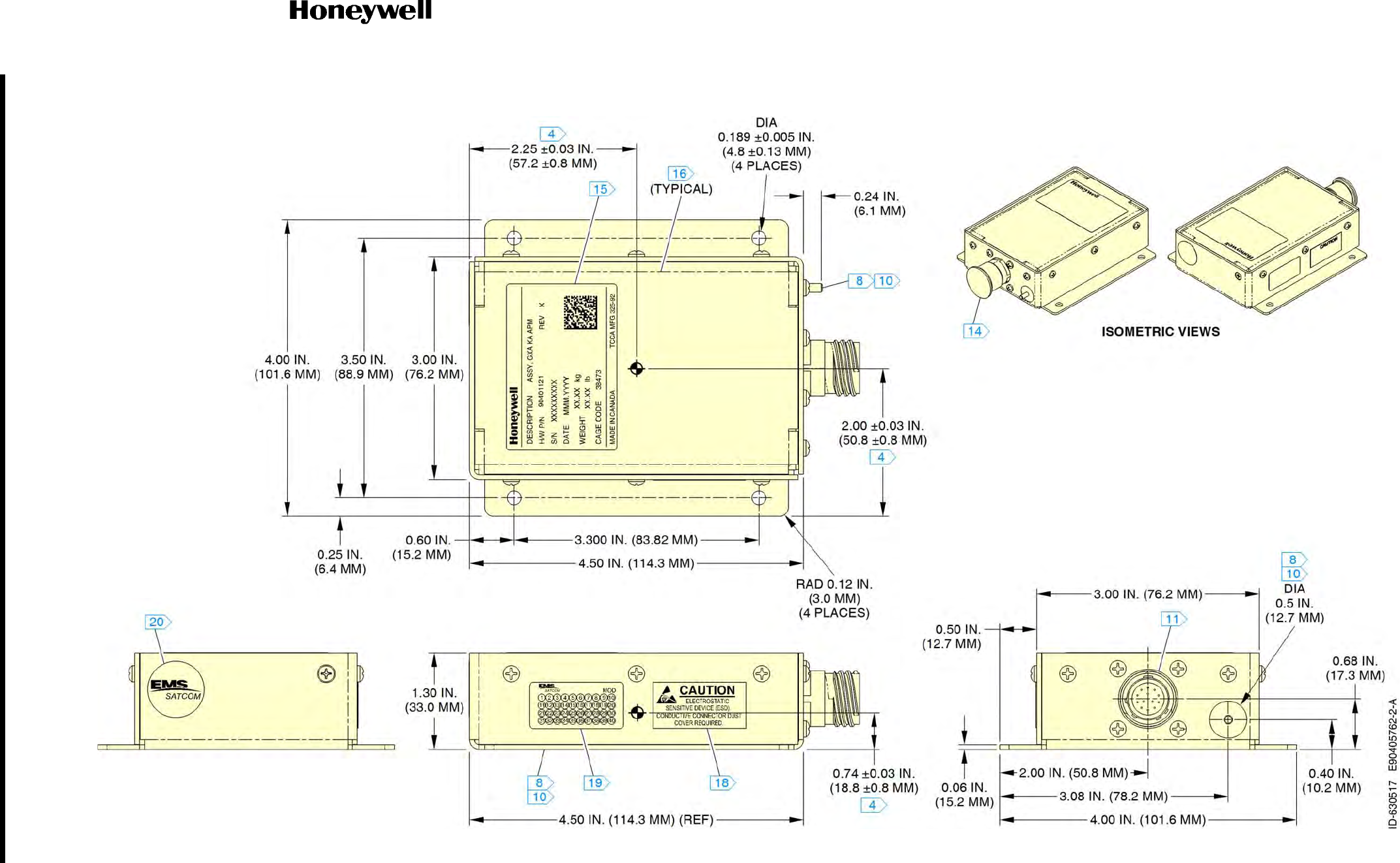
Refer to Figure 4-24 for the APM (PN 90405762) outline and installation drawing.
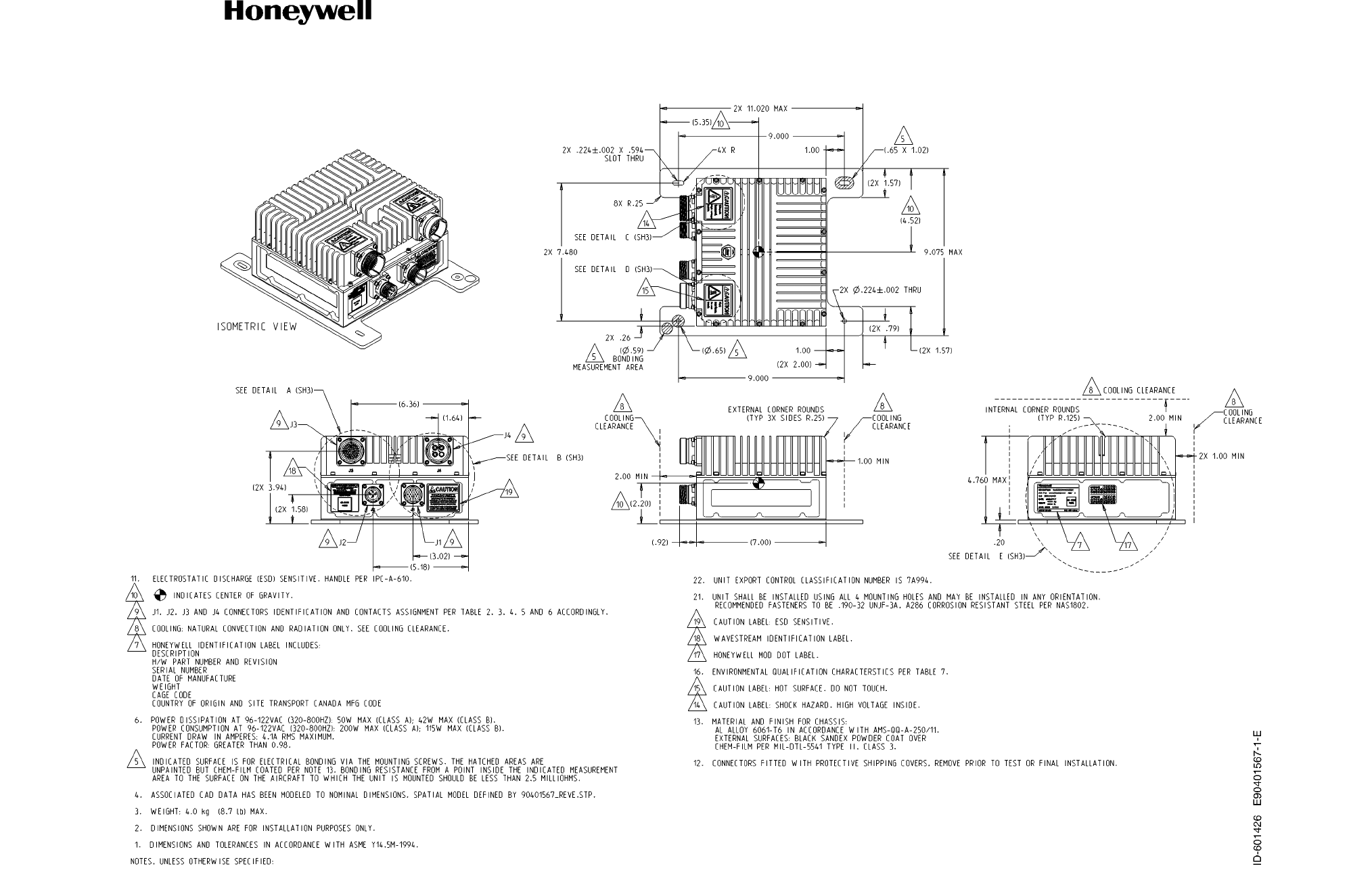
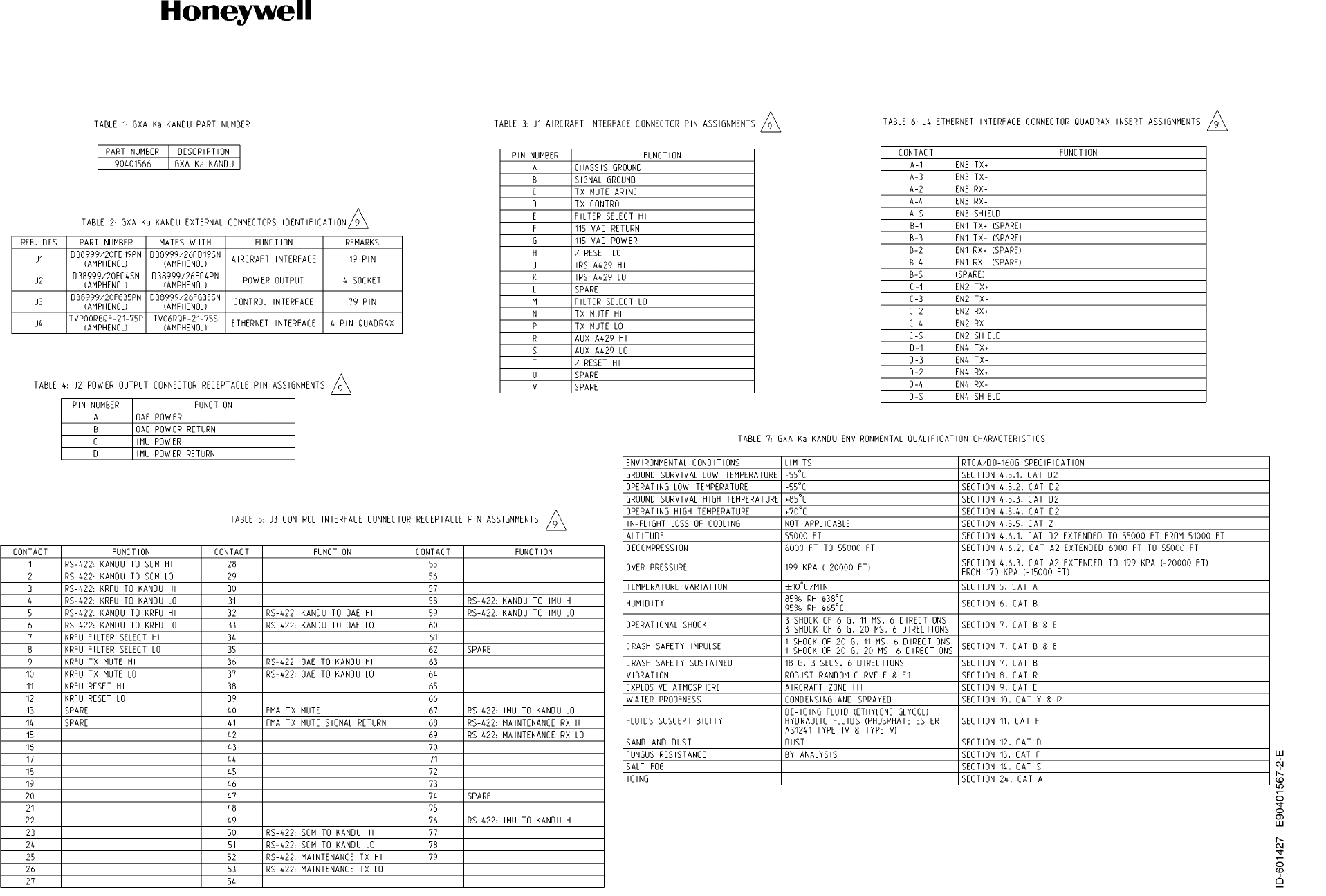
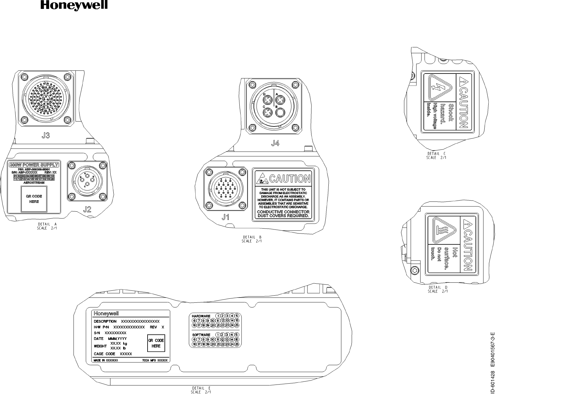
Refer to Figure 4-25 for the KANDU (PN 90401657) outline and installation drawing.
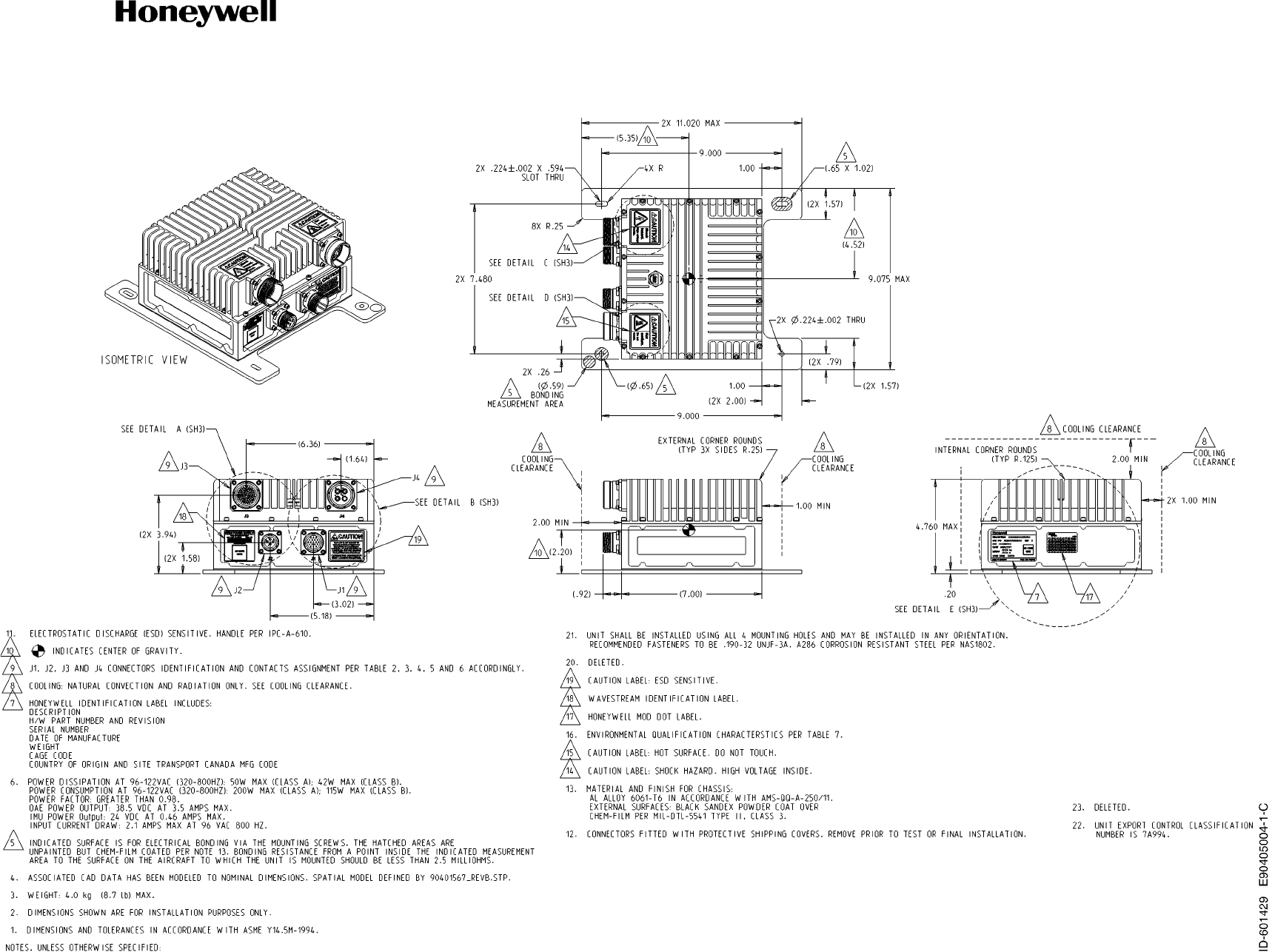
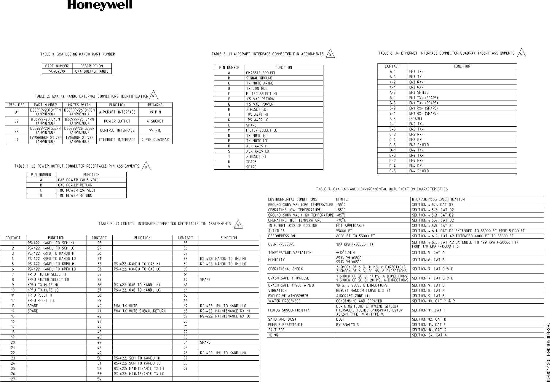
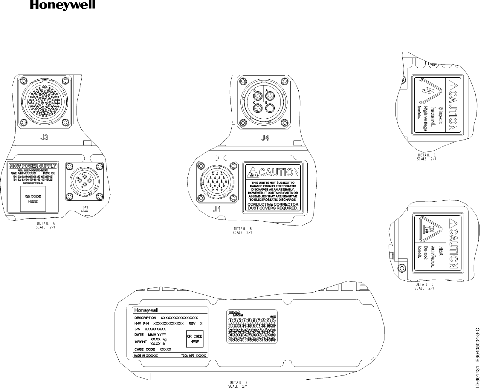
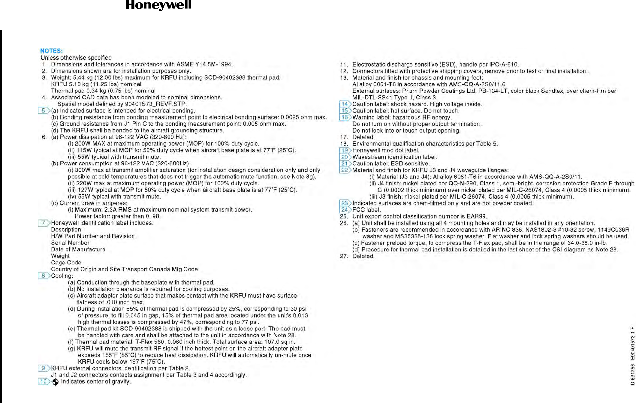
Refer to Figure 4-26 for the KANDU Variant 2 (PN 90405004) outline and installation drawing.
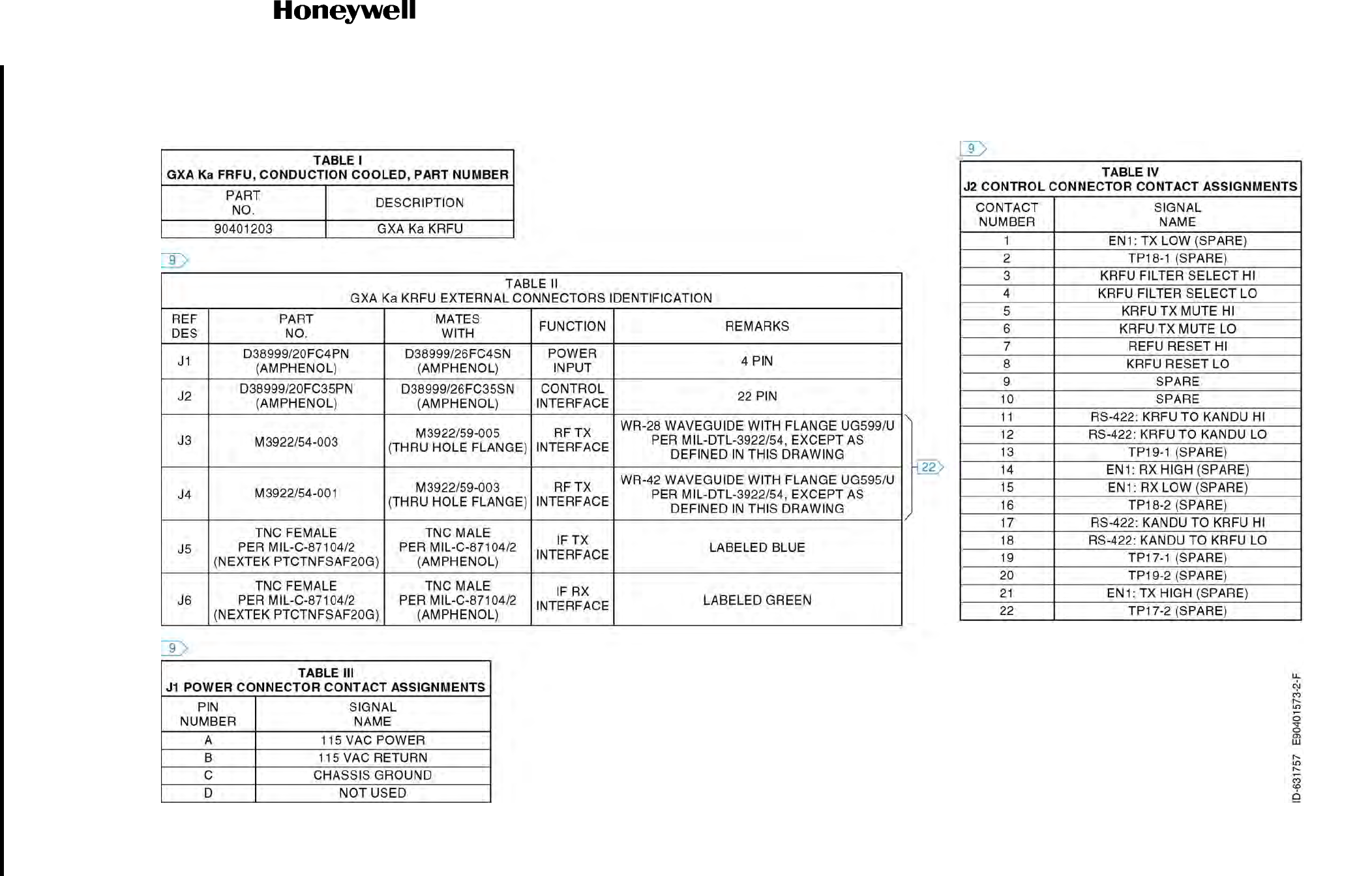
Refer to Figure 4-27 for the KRFU (PN 90401573), conduction-cooled 1 (maximum operating temperature
of 185°F (85°C)), outline and installation drawing.
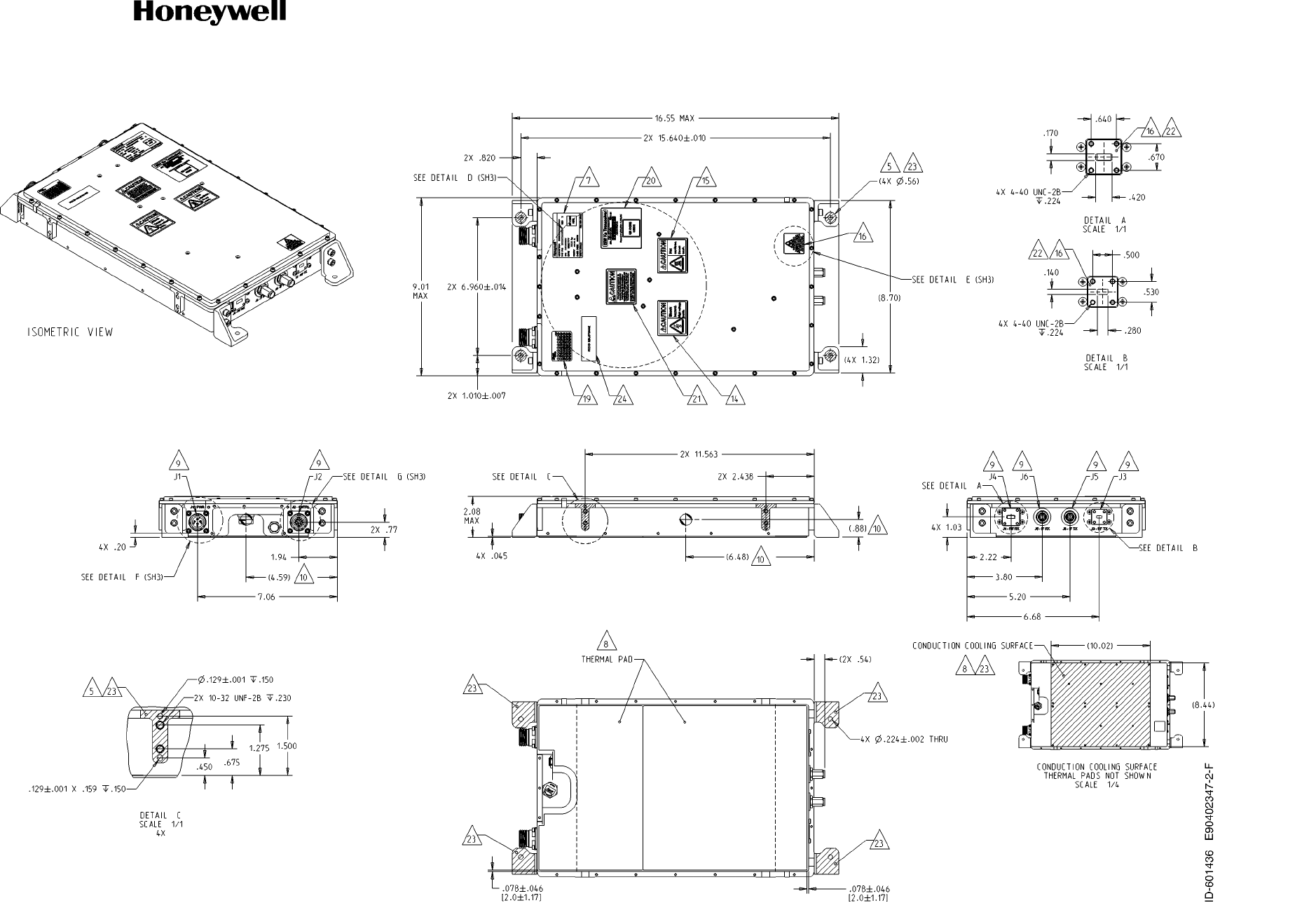
Refer to Figure 4-28 for the KRFU (PN 90402347), conduction-cooled 2 (maximum operating temperature
of 158°F (70°C)), outline and installation drawing.
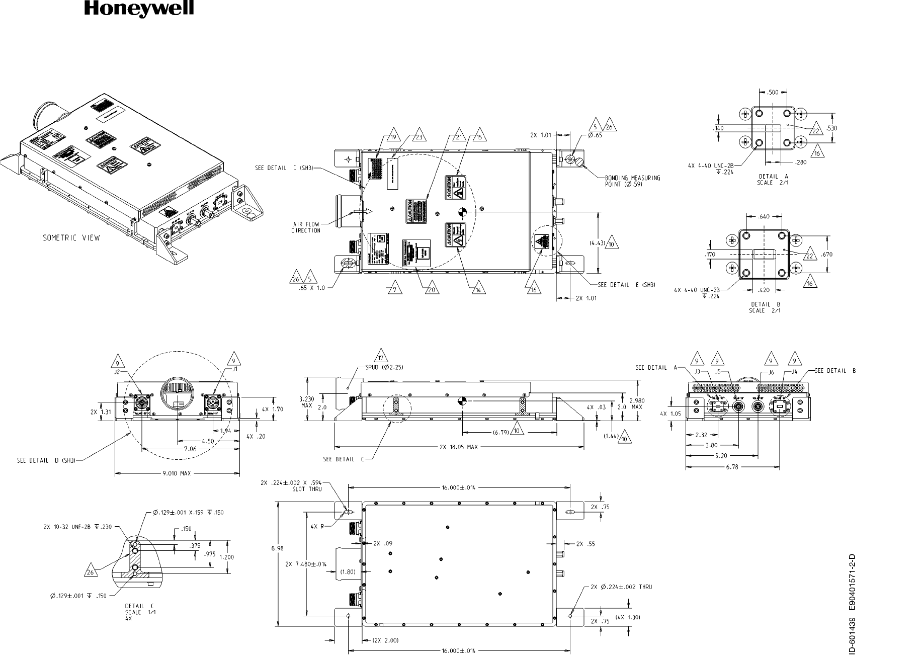
Refer to Figure 4-29 for the KRFU (PN 90401571), forced air cooled, outline and installation drawing.
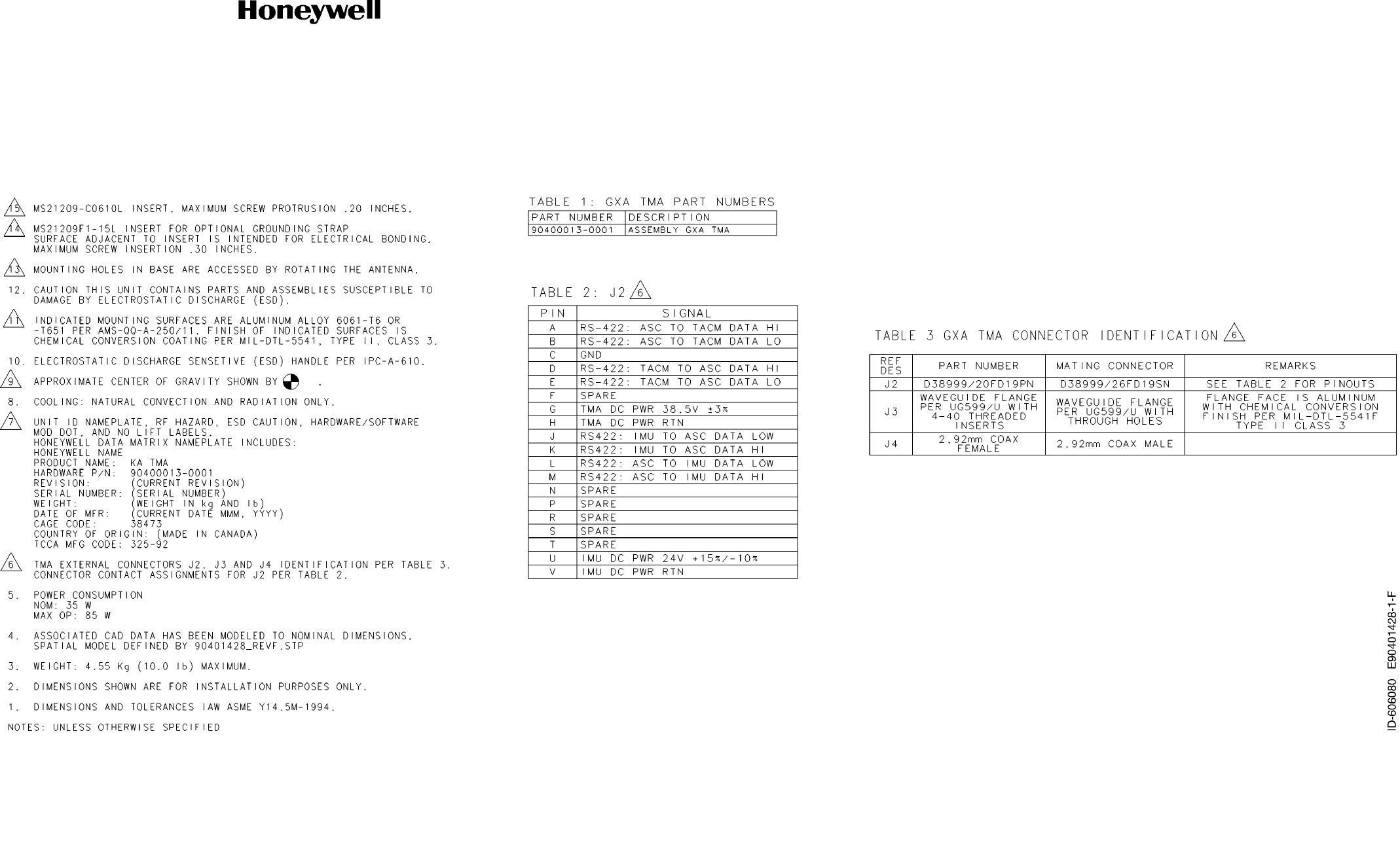
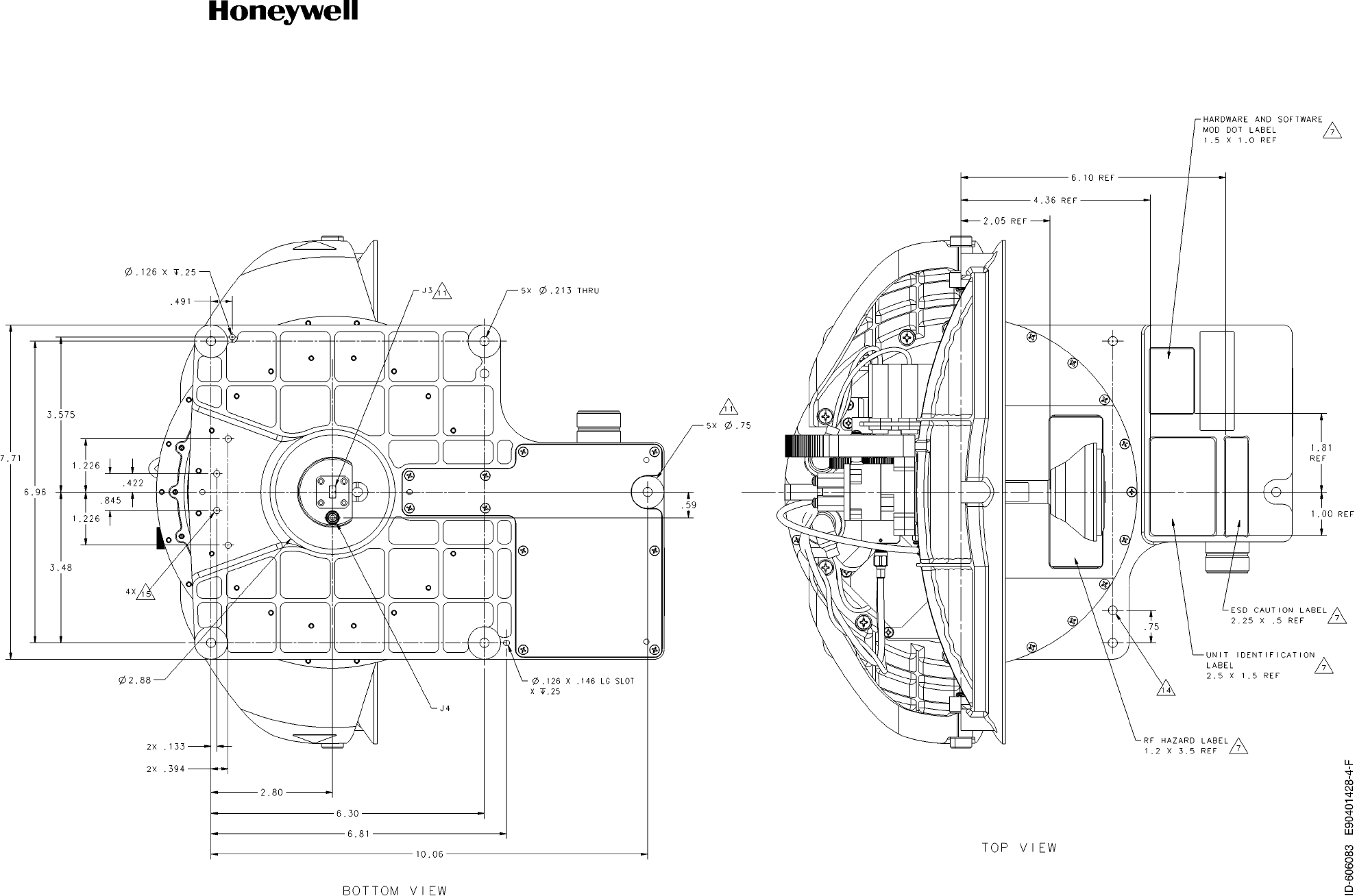
Refer to Figure 4-30 for the TMA (PN 90401428) outline and installation drawing.
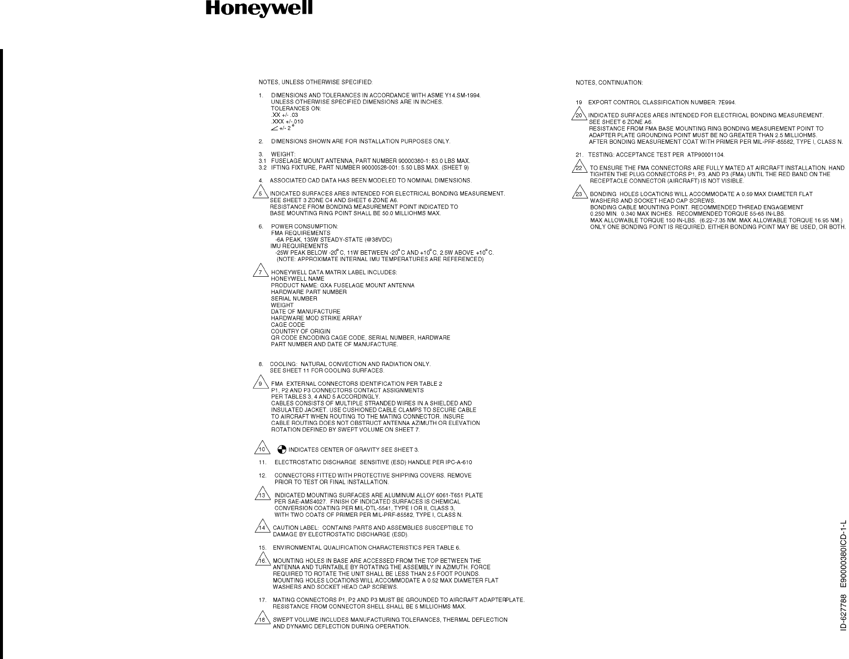
Refer to Figure 4-31 for the FMA (PN 90000380ICD) outline and installation drawing.
Refer to Figure 4-32 for the Fuselage Mount Radome (PN 90401395) outline and installation drawing.
NOTE: The Fuselage Mount Radome is offered as a standard part and varying skirts can be used to
adapt this to different airframe platforms. No Tail Mount Radome is depicted as this is airframe
platform specific.
Table 4-10. Cabling Requirements
Cable Conductor Type Single
Point Multiple
Point Minimum Conductor
Coverage by Shield
Power Lines Twisted pair NA NA NA
Ethernet Data Quadrax, twisted pair - Yes 100%
RF Coaxial, waveguide - Yes 100%
A429 Twisted pair, stranded - Yes 95%
RS-422 Twisted pair, shielded - Yes 100%
Discrete Twisted pair, shielded, KANDU
Single conductor, shielded, grounds - Yes 100%
Draft as of 31 May 2017

Page 4-42
3 Mar 2017
23-15-29
SYSTEM DESCRIPTION AND INSTALLATION MANUAL
JetWave™ System
© Honeywell International Inc. Do not copy without express permission of Honeywell.
Refer to Figure 4-33 for the LAIM (PN 90404861) outline and installation drawing.
Refer to Figure 4-34 for the JetWave™ System - TMA (PN 90400189-0001) interconnect diagram.
Refer to Figure 4-35 for the JetWave™ System - FMA (KRFU inside aircraft fuselage) (PN
90400259-0001) interconnect diagram.
Refer to Figure 4-36 for the JetWave™ System - FMA (KRFU outside Aircraft Fuselage) (PN 90401047-1)
interconnect diagram.
Refer to Figure 4-37 for the JetWave™ System - FMA (Alternative KRFU outside Aircraft fuselage) (PN
90405210) interconnect diagram.
Draft as of 31 May 2017
SYSTEM DESCRIPTION AND INSTALLATION MANUAL
JetWave™ System
Page 4-45
3 Mar 2017
© Honeywell International Inc. Do not copy without express permission of Honeywell.
23-15-29
Figure 4-21. (Sheet 1 of 4) Modman Outline and Installation Drawing (90400059-0001, REV F)
Draft as of 31 May 2017
SYSTEM DESCRIPTION AND INSTALLATION MANUAL
JetWave™ System
Page 4-46
3 Mar 2017
© Honeywell International Inc. Do not copy without express permission of Honeywell.
23-15-29
Figure 4-21. (Sheet 2 of 4) Modman Outline and Installation Drawing (90400059-0001, REV F)
Draft as of 31 May 2017
SYSTEM DESCRIPTION AND INSTALLATION MANUAL
JetWave™ System
Page 4-47
3 Mar 2017
© Honeywell International Inc. Do not copy without express permission of Honeywell.
23-15-29
Figure 4-21. (Sheet 3 of 4) Modman Outline and Installation Drawing (90400059-0001, REV F)
Draft as of 31 May 2017
SYSTEM DESCRIPTION AND INSTALLATION MANUAL
JetWave™ System
Page 4-48
3 Mar 2017
© Honeywell International Inc. Do not copy without express permission of Honeywell.
23-15-29
Figure 4-21. (Sheet 4 of 4) Modman Outline and Installation Drawing (90400059-0001, REV F)
Draft as of 31 May 2017
SYSTEM DESCRIPTION AND INSTALLATION MANUAL
JetWave™ System
Page 4-49
3 Mar 2017
© Honeywell International Inc. Do not copy without express permission of Honeywell.
23-15-29
Figure 4-22. (Sheet 1 of 4) Modman Outline and Installation Drawing Variant 2 (90400059-0002, REV A)
Draft as of 31 May 2017
SYSTEM DESCRIPTION AND INSTALLATION MANUAL
JetWave™ System
Page 4-50
3 Mar 2017
© Honeywell International Inc. Do not copy without express permission of Honeywell.
23-15-29
Figure 4-22. (Sheet 2 of 4) Modman Outline and Installation Drawing Variant 2 (90400059-0002, REV A)
Draft as of 31 May 2017
SYSTEM DESCRIPTION AND INSTALLATION MANUAL
JetWave™ System
Page 4-51
3 Mar 2017
© Honeywell International Inc. Do not copy without express permission of Honeywell.
23-15-29
Figure 4-22. (Sheet 3 of 4) Modman Outline and Installation Drawing Variant 2 (90400059-0002, REV A)
Draft as of 31 May 2017
SYSTEM DESCRIPTION AND INSTALLATION MANUAL
JetWave™ System
Page 4-52
3 Mar 2017
© Honeywell International Inc. Do not copy without express permission of Honeywell.
23-15-29
Figure 4-22. (Sheet 4 of 4) Modman Outline and Installation Drawing Variant 2 (90400059-0002, REV A)
Draft as of 31 May 2017
SYSTEM DESCRIPTION AND INSTALLATION MANUAL
JetWave™ System
Page 4-53
3 Mar 2017
© Honeywell International Inc. Do not copy without express permission of Honeywell.
23-15-29
Figure 4-23. (Sheet 1 of 2) APM Outline and Installation Drawing (90401592, REV F)
Draft as of 31 May 2017
SYSTEM DESCRIPTION AND INSTALLATION MANUAL
JetWave™ System
Page 4-54
3 Mar 2017
© Honeywell International Inc. Do not copy without express permission of Honeywell.
23-15-29
Figure 4-23. (Sheet 2 of 2) APM Outline and Installation Drawing (90401592, REV F)
Draft as of 31 May 2017
SYSTEM DESCRIPTION AND INSTALLATION MANUAL
JetWave™ System
Page 4-55
3 Mar 2017
© Honeywell International Inc. Do not copy without express permission of Honeywell.
23-15-29
Figure 4-24. (Sheet 1 of 2) APM Outline and Installation Drawing (90405762, REV A)
Draft as of 31 May 2017
SYSTEM DESCRIPTION AND INSTALLATION MANUAL
JetWave™ System
Page 4-56
3 Mar 2017
© Honeywell International Inc. Do not copy without express permission of Honeywell.
23-15-29
Figure 4-24. (Sheet 2 of 2) APM Outline and Installation Drawing (90405762, REV A)
Draft as of 31 May 2017
SYSTEM DESCRIPTION AND INSTALLATION MANUAL
JetWave™ System
Page 4-57
3 Mar 2017
© Honeywell International Inc. Do not copy without express permission of Honeywell.
23-15-29
Figure 4-25. (Sheet 1 of 3) KANDU Outline and Installation Drawing (90401657, REV E)
Draft as of 31 May 2017
SYSTEM DESCRIPTION AND INSTALLATION MANUAL
JetWave™ System
Page 4-58
3 Mar 2017
© Honeywell International Inc. Do not copy without express permission of Honeywell.
23-15-29
Figure 4-25. (Sheet 2 of 3) KANDU Outline and Installation Drawing (90401657, REV E)
Draft as of 31 May 2017
SYSTEM DESCRIPTION AND INSTALLATION MANUAL
JetWave™ System
Page 4-59
3 Mar 2017
© Honeywell International Inc. Do not copy without express permission of Honeywell.
23-15-29
Figure 4-25. (Sheet 3 of 3) KANDU Outline and Installation Drawing (90401657, REV E)
Draft as of 31 May 2017
SYSTEM DESCRIPTION AND INSTALLATION MANUAL
JetWave™ System
Page 4-60
3 Mar 2017
© Honeywell International Inc. Do not copy without express permission of Honeywell.
23-15-29
Figure 4-26. (Sheet 1 of 3) KANDU Variant 2 Outline and Installation Drawing (90405004, REV C)
Draft as of 31 May 2017
SYSTEM DESCRIPTION AND INSTALLATION MANUAL
JetWave™ System
Page 4-61
3 Mar 2017
© Honeywell International Inc. Do not copy without express permission of Honeywell.
23-15-29
Figure 4-26. (Sheet 2 of 3) KANDU Variant 2 Outline and Installation Drawing (90405004, REV C)
Draft as of 31 May 2017
SYSTEM DESCRIPTION AND INSTALLATION MANUAL
JetWave™ System
Page 4-62
3 Mar 2017
© Honeywell International Inc. Do not copy without express permission of Honeywell.
23-15-29
Figure 4-26. (Sheet 3 of 3) KANDU Variant 2 Outline and Installation Drawing (90405004, REV C)
Draft as of 31 May 2017
SYSTEM DESCRIPTION AND INSTALLATION MANUAL
JetWave™ System
Page 4-63
3 Mar 2017
© Honeywell International Inc. Do not copy without express permission of Honeywell.
23-15-29
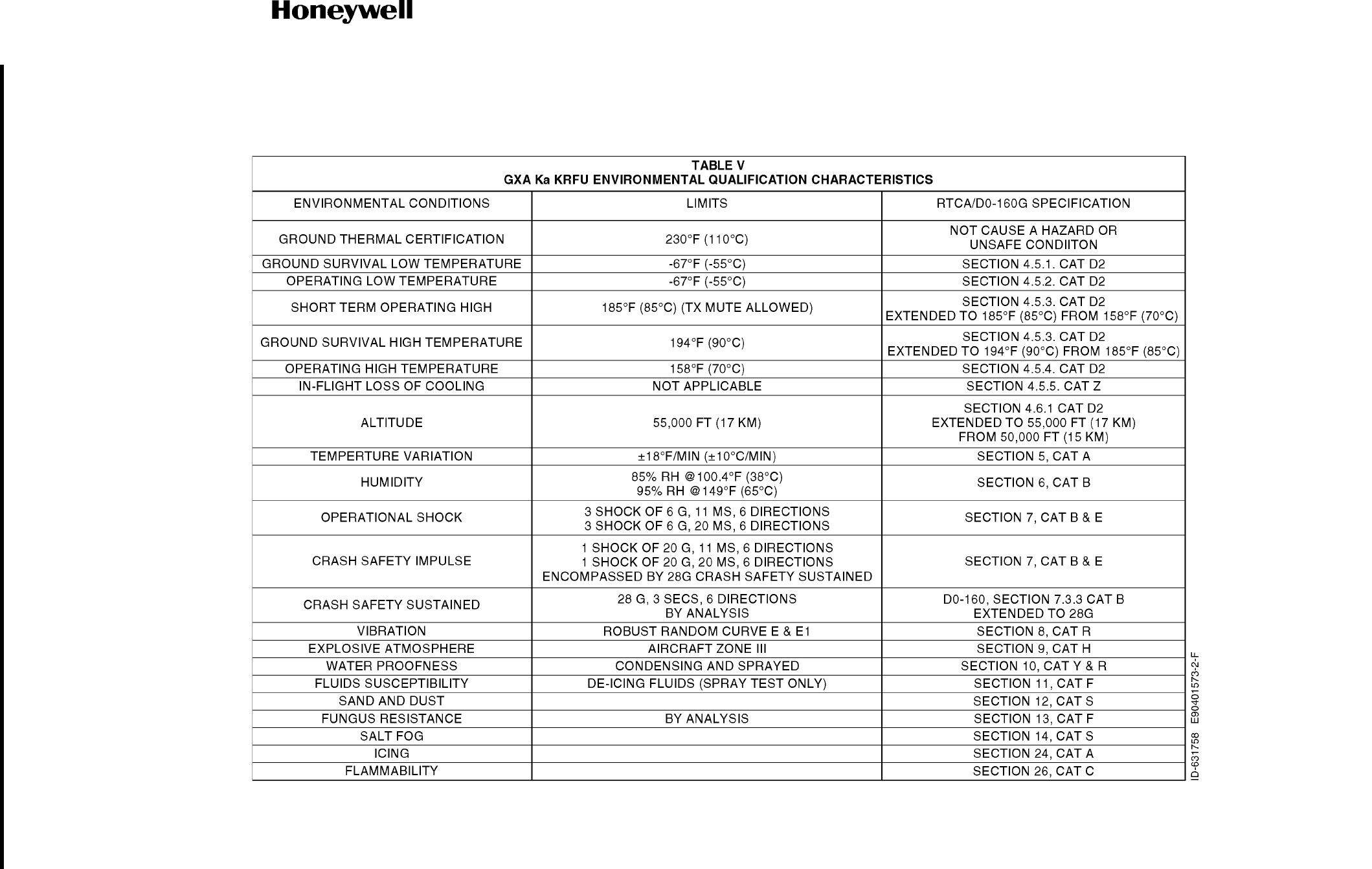
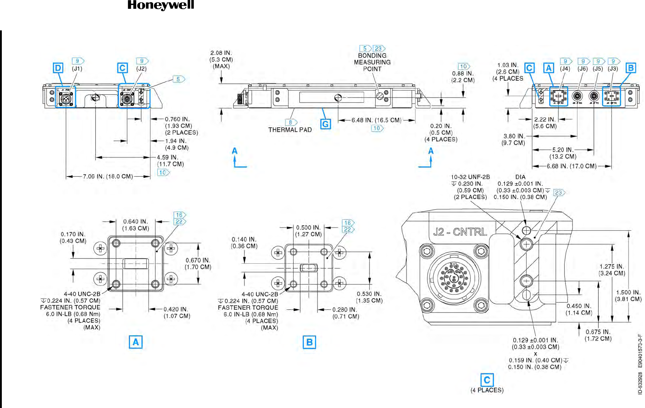
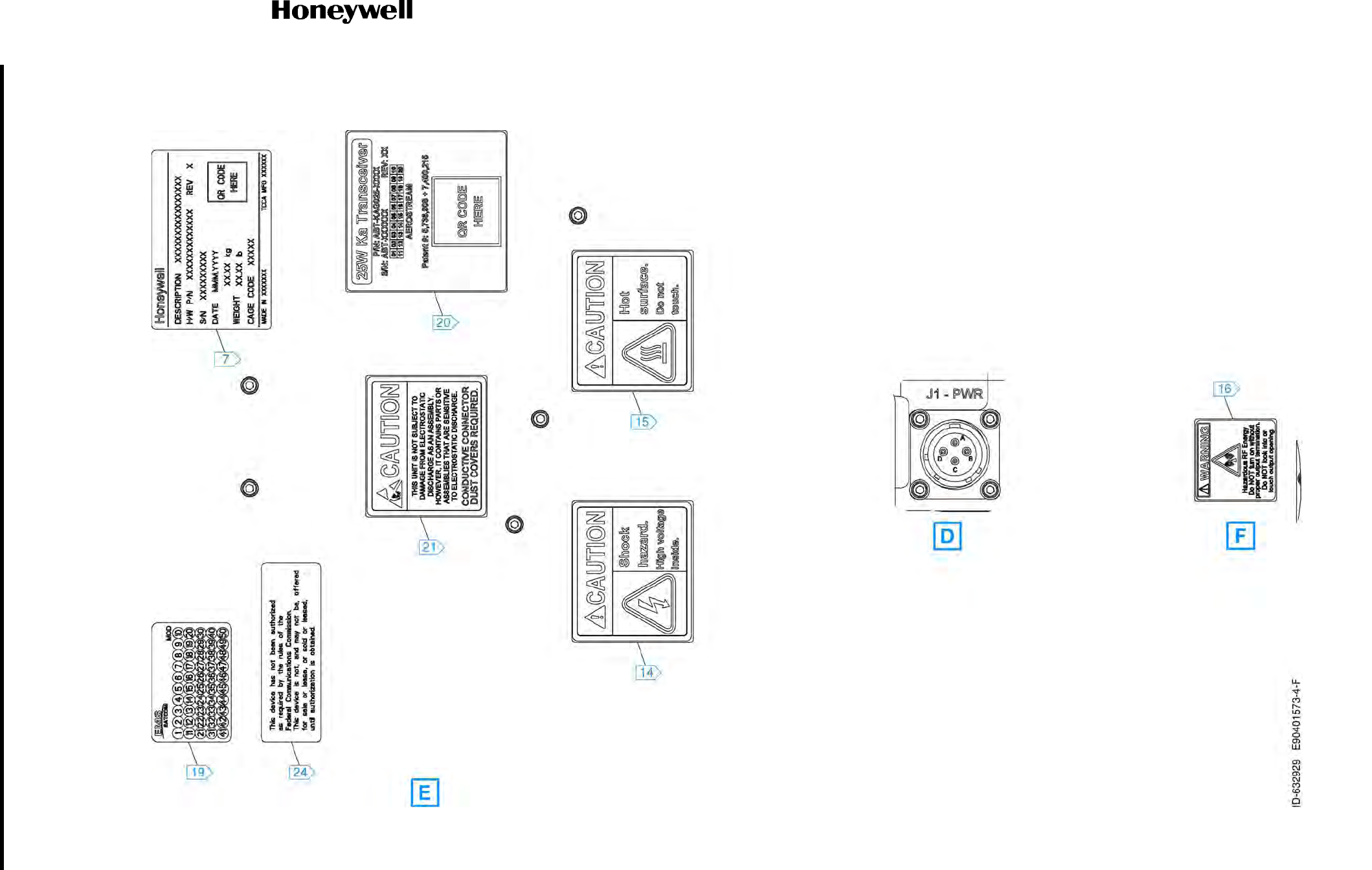
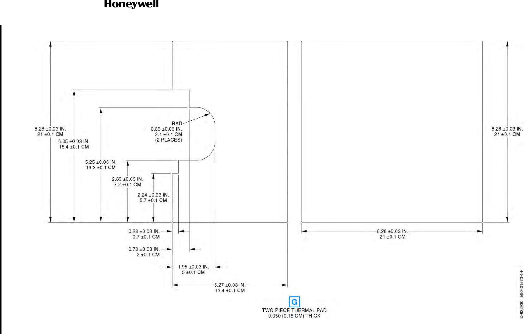
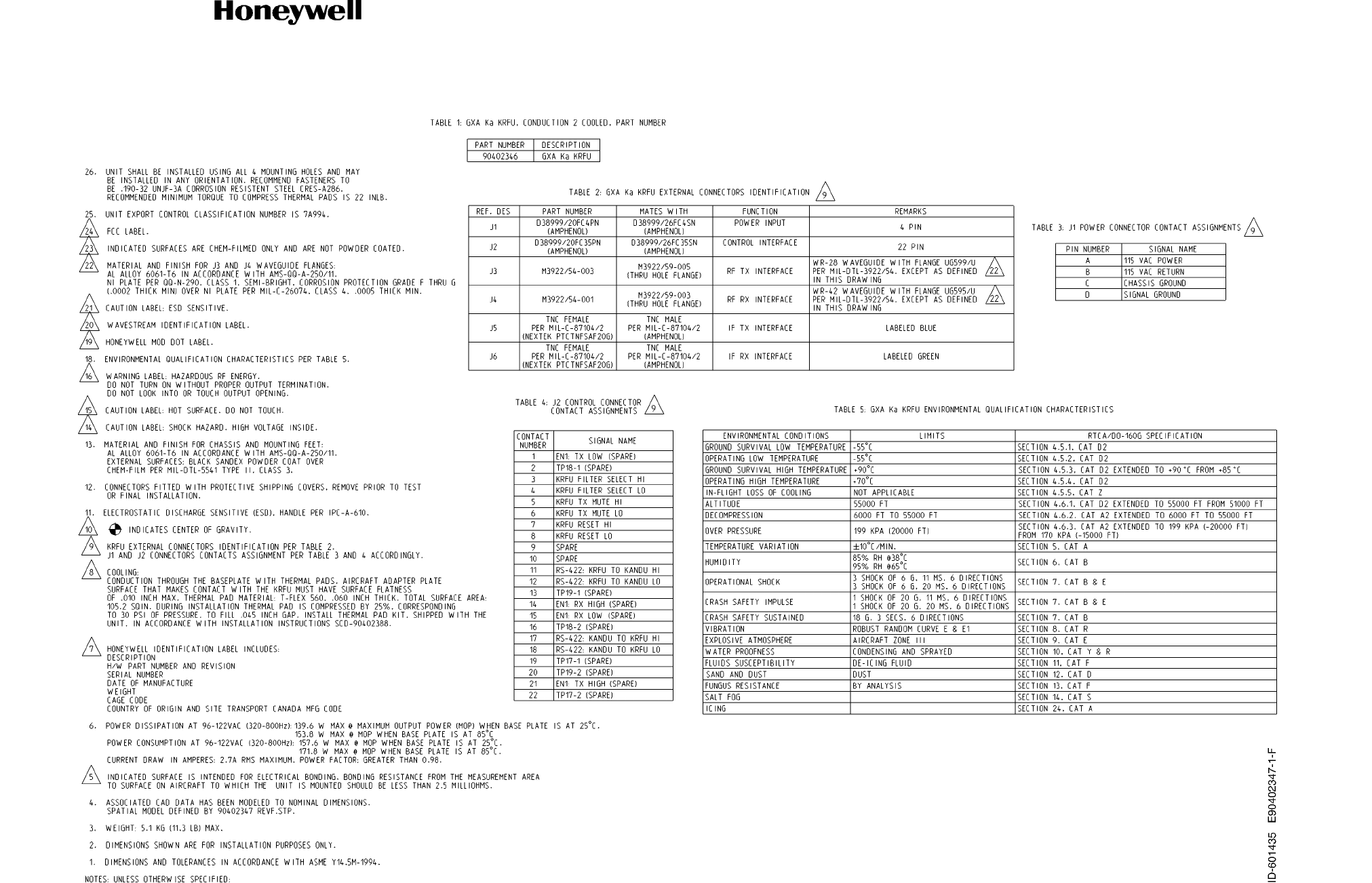
Figure 4-27. (Sheet 1 of 9) KRFU, Conduction-Cooled 1, Outline and Installation Drawing (90401573, REV F)
Draft as of 31 May 2017
SYSTEM DESCRIPTION AND INSTALLATION MANUAL
JetWave™ System
Page 4-64
3 Mar 2017
© Honeywell International Inc. Do not copy without express permission of Honeywell.
23-15-29
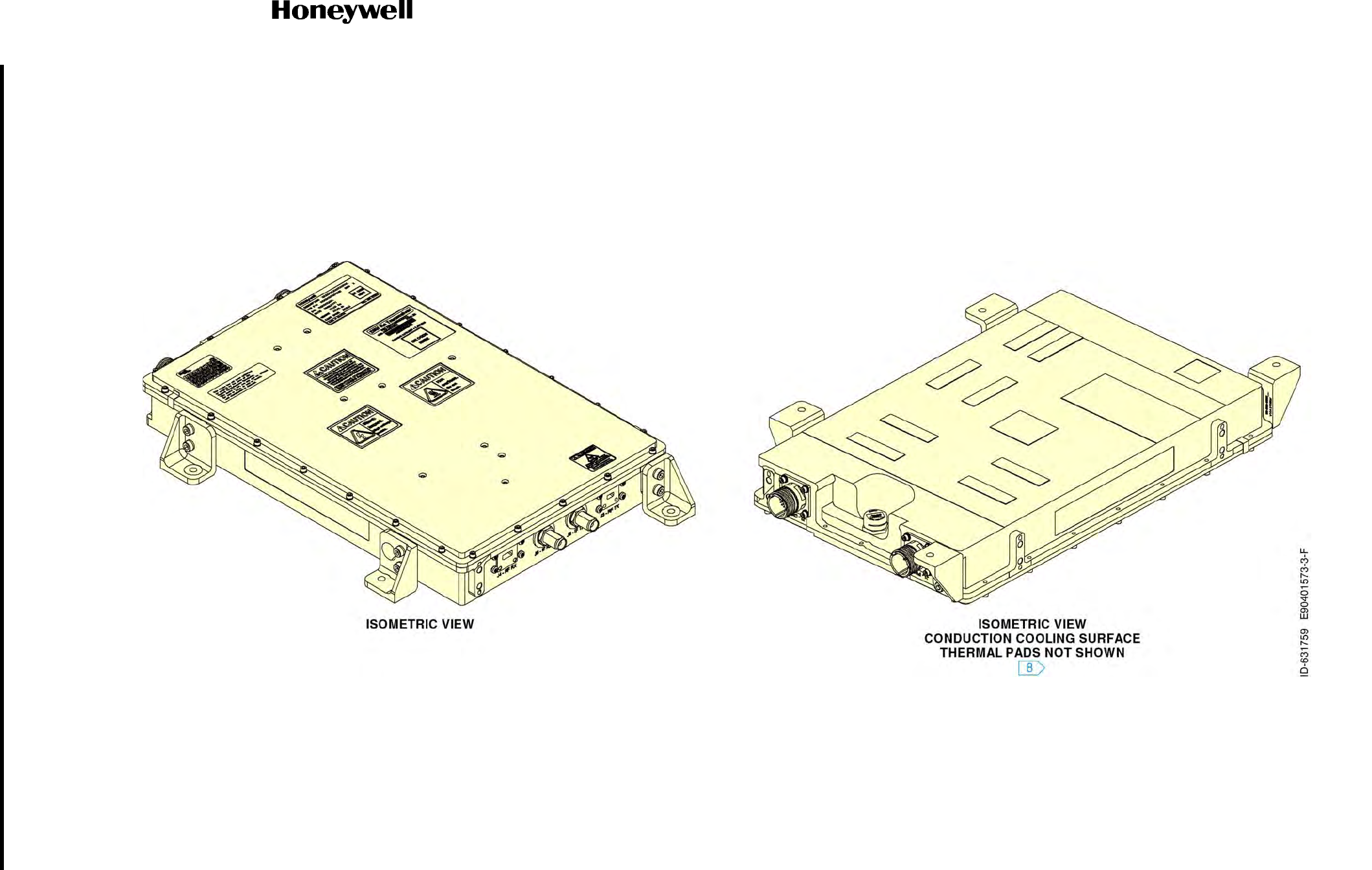
Figure 4-27. (Sheet 2 of 9) KRFU, Conduction-Cooled 1, Outline and Installation Drawing (90401573, REV F)
Draft as of 31 May 2017
SYSTEM DESCRIPTION AND INSTALLATION MANUAL
JetWave™ System
Page 4-65
3 Mar 2017
© Honeywell International Inc. Do not copy without express permission of Honeywell.
23-15-29
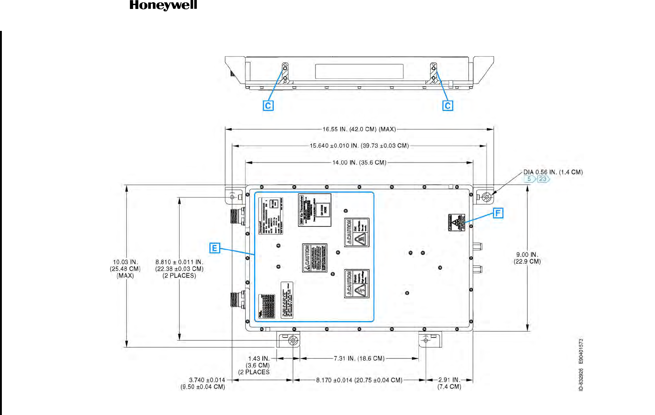
Figure 4-27. (Sheet 3 of 9) KRFU, Conduction-Cooled 1, Outline and Installation Drawing (90401573, REV F)
Draft as of 31 May 2017
SYSTEM DESCRIPTION AND INSTALLATION MANUAL
JetWave™ System
Page 4-66
3 Mar 2017
© Honeywell International Inc. Do not copy without express permission of Honeywell.
23-15-29
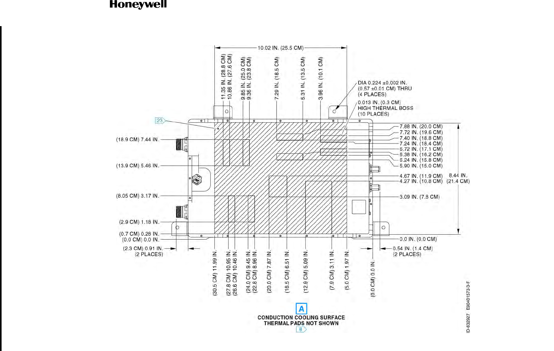
Figure 4-27. (Sheet 4 of 9) KRFU, Conduction-Cooled 1, Outline and Installation Drawing (90401573, REV F)
Draft as of 31 May 2017
SYSTEM DESCRIPTION AND INSTALLATION MANUAL
JetWave™ System
Page 4-67
3 Mar 2017
© Honeywell International Inc. Do not copy without express permission of Honeywell.
23-15-29
Figure 4-27. (Sheet 5 of 9) KRFU, Conduction-Cooled 1, Outline and Installation Drawing (90401573, REV F)
Draft as of 31 May 2017
SYSTEM DESCRIPTION AND INSTALLATION MANUAL
JetWave™ System
Page 4-68
3 Mar 2017
© Honeywell International Inc. Do not copy without express permission of Honeywell.
23-15-29
Figure 4-27. (Sheet 6 of 9) KRFU, Conduction-Cooled 1, Outline and Installation Drawing (90401573, REV F)
Draft as of 31 May 2017
SYSTEM DESCRIPTION AND INSTALLATION MANUAL
JetWave™ System
Page 4-69
3 Mar 2017
© Honeywell International Inc. Do not copy without express permission of Honeywell.
23-15-29
Figure 4-27. (Sheet 7 of 9) KRFU, Conduction-Cooled 1, Outline and Installation Drawing (90401573, REV F)
Draft as of 31 May 2017
SYSTEM DESCRIPTION AND INSTALLATION MANUAL
JetWave™ System
Page 4-70
3 Mar 2017
© Honeywell International Inc. Do not copy without express permission of Honeywell.
23-15-29
Figure 4-27. (Sheet 8 of 9) KRFU, Conduction-Cooled 1, Outline and Installation Drawing (90401573, REV F)
Draft as of 31 May 2017
SYSTEM DESCRIPTION AND INSTALLATION MANUAL
JetWave™ System
Page 4-71
3 Mar 2017
© Honeywell International Inc. Do not copy without express permission of Honeywell.
23-15-29
Figure 4-27. (Sheet 9 of 9) KRFU, Conduction-Cooled 1, Outline and Installation Drawing (90401573, REV F)
Draft as of 31 May 2017
SYSTEM DESCRIPTION AND INSTALLATION MANUAL
JetWave™ System
Page 4-72
3 Mar 2017
© Honeywell International Inc. Do not copy without express permission of Honeywell.
23-15-29
Figure 4-28. (Sheet 1 of 3) KRFU, Conduction-Cooled 2, Outline and Installation Drawing (90402347, REV F)
Draft as of 31 May 2017
SYSTEM DESCRIPTION AND INSTALLATION MANUAL
JetWave™ System
Page 4-73
3 Mar 2017
© Honeywell International Inc. Do not copy without express permission of Honeywell.
23-15-29
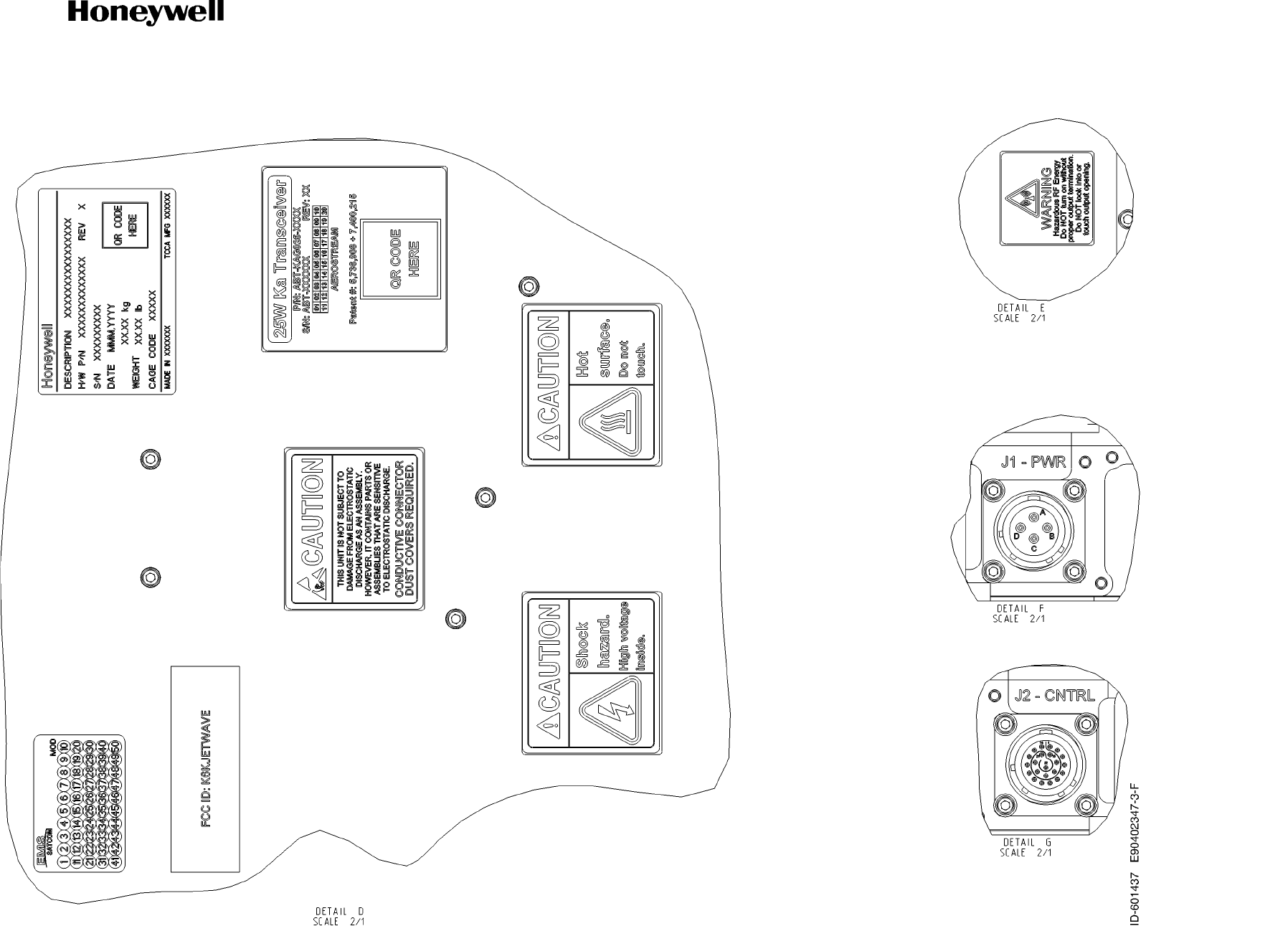
Figure 4-28. (Sheet 2 of 3) KRFU, Conduction-Cooled 2, Outline and Installation Drawing (90402347, REV F)
Draft as of 31 May 2017
SYSTEM DESCRIPTION AND INSTALLATION MANUAL
JetWave™ System
Page 4-74
3 Mar 2017
© Honeywell International Inc. Do not copy without express permission of Honeywell.
23-15-29
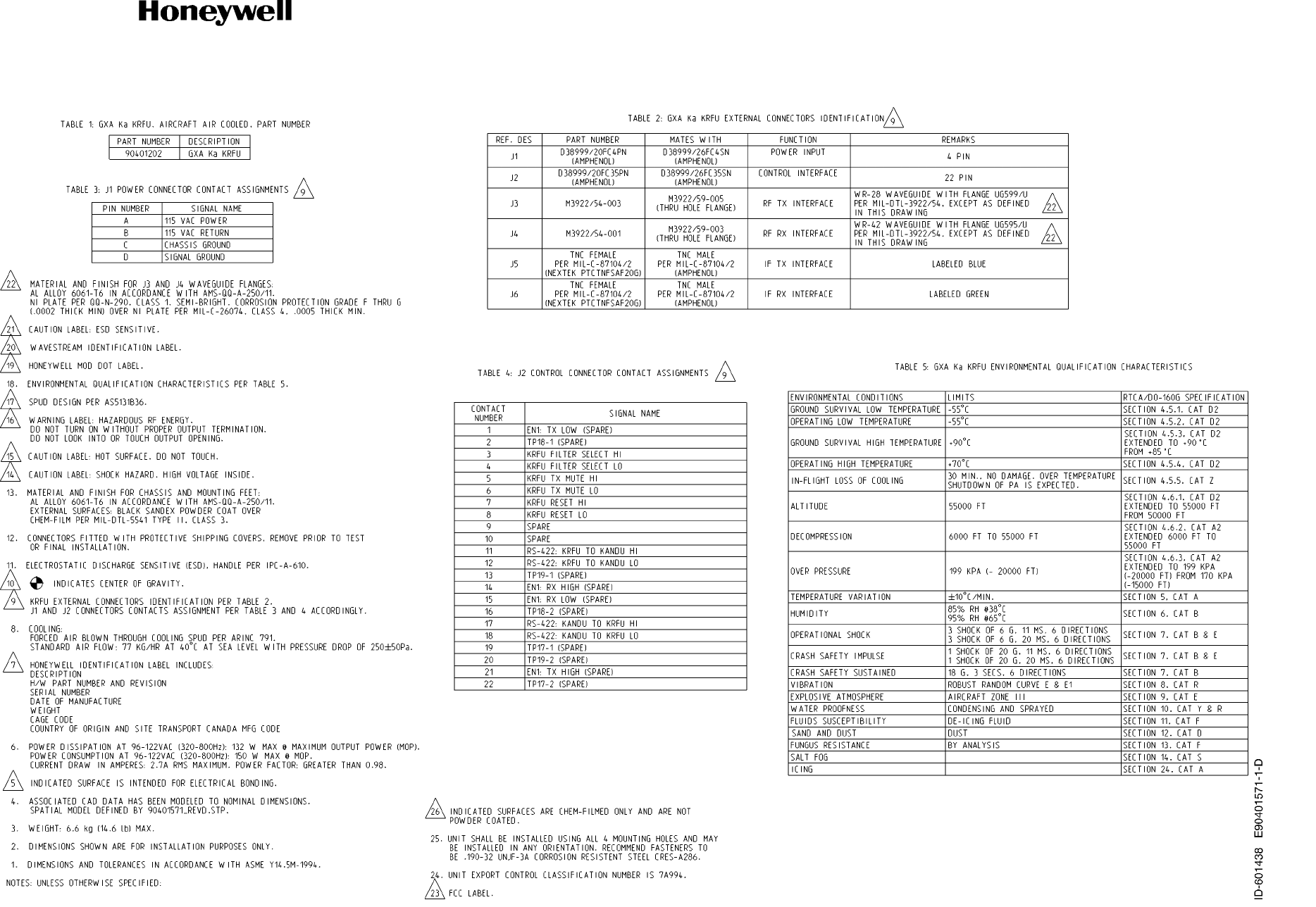
Figure 4-28. (Sheet 3 of 3) KRFU, Conduction-Cooled 2, Outline and Installation Drawing (90402347, REV F)
Draft as of 31 May 2017
SYSTEM DESCRIPTION AND INSTALLATION MANUAL
JetWave™ System
Page 4-75
3 Mar 2017
© Honeywell International Inc. Do not copy without express permission of Honeywell.
23-15-29
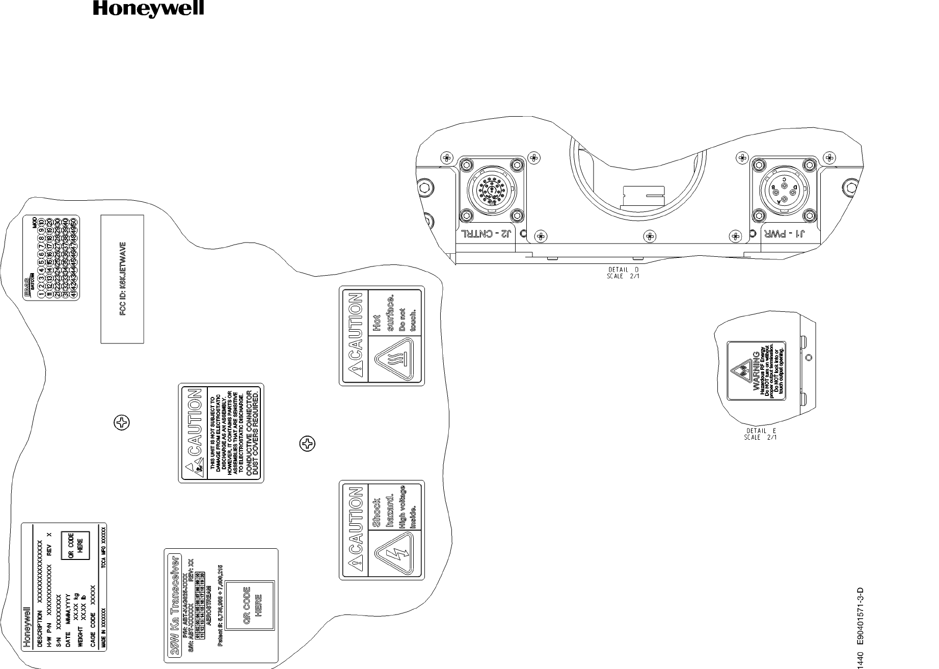
Figure 4-29. (Sheet 1 of 3) KRFU, Forced Air Cooled, Outline and Installation Drawing (90401571, REV D)
Draft as of 31 May 2017
SYSTEM DESCRIPTION AND INSTALLATION MANUAL
JetWave™ System
Page 4-76
3 Mar 2017
© Honeywell International Inc. Do not copy without express permission of Honeywell.
23-15-29
Figure 4-29. (Sheet 2 of 3) KRFU, Forced Air Cooled, Outline and Installation Drawing (90401571, REV D)
Draft as of 31 May 2017
SYSTEM DESCRIPTION AND INSTALLATION MANUAL
JetWave™ System
Page 4-77
3 Mar 2017
© Honeywell International Inc. Do not copy without express permission of Honeywell.
23-15-29
Figure 4-29. (Sheet 3 of 3) KRFU, Forced Air Cooled, Outline and Installation Drawing (90401571, REV D)
Draft as of 31 May 2017
SYSTEM DESCRIPTION AND INSTALLATION MANUAL
JetWave™ System
Page 4-78
3 Mar 2017
© Honeywell International Inc. Do not copy without express permission of Honeywell.
23-15-29
Figure 4-30. (Sheet 1 of 4) TMA Outline and Installation Drawing (90401428, REV F)
Draft as of 31 May 2017
SYSTEM DESCRIPTION AND INSTALLATION MANUAL
JetWave™ System
Page 4-79
3 Mar 2017
© Honeywell International Inc. Do not copy without express permission of Honeywell.
23-15-29
Figure 4-30. (Sheet 2 of 4) TMA Outline and Installation Drawing (90401428, REV F)
Draft as of 31 May 2017
SYSTEM DESCRIPTION AND INSTALLATION MANUAL
JetWave™ System
Page 4-80
3 Mar 2017
© Honeywell International Inc. Do not copy without express permission of Honeywell.
23-15-29
Figure 4-30. (Sheet 3 of 4) TMA Outline and Installation Drawing (90401428, REV F)
Draft as of 31 May 2017
SYSTEM DESCRIPTION AND INSTALLATION MANUAL
JetWave™ System
Page 4-81
3 Mar 2017
© Honeywell International Inc. Do not copy without express permission of Honeywell.
23-15-29
Figure 4-30. (Sheet 4 of 4) TMA Outline and Installation Drawing (90401428, REV F)
Draft as of 31 May 2017
SYSTEM DESCRIPTION AND INSTALLATION MANUAL
JetWave™ System
Page 4-82
3 Mar 2017
© Honeywell International Inc. Do not copy without express permission of Honeywell.
23-15-29
Figure 4-31. (Sheet 1 of 14) FMA Outline and Installation Drawing (90000380ICD, REV L)
Draft as of 31 May 2017