EMS Technologies 020MCELL1900 MIRRORCELL II PCS REPEATER User Manual USERS MANUAL
EMS Technologies MIRRORCELL II PCS REPEATER USERS MANUAL
USERS MANUAL

5015 B.U. Bowman Drive Buford, GA 30518 USA Voice: 770-831-8048 Fax: 770-831-8598
FCC Part 24E
Transmitter Certification
Test Report
FCC ID: DNY020MCELL1900
FCC Rule Part: CFR 47 Part 24 Subpart E
ACS Report Number: 06-0347-24E
Manufacturer: EMS Wireless
Equipment Type: PCS Bi-Directional Repeater
Tradename: MirrorCell® II
Model: CDM1912-743
Manual
EMS Wireless Operator’s Manual
MirrorCell II CDM 812, CDM1912 Series
608112-1, Rev C
1
Operator’s Manual
MirrorCell II
Repeater
CDM 812, CDM1912 Series
2850 Colonnades Court
Norcross, GA 30071 U. S. A.
770.582.0555
Fax 770.729.0075

EMS Wireless Operator’s Manual
MirrorCell II CDM 812, CDM1912 Series
608112-1, Rev C
2
Disclaimer
Every attempt has been made to make this material complete, accurate, and up-to-
date. Users are cautioned, however, that EMS Wireless reserves the right to make
changes without notice and shall not be responsible for any damages, including
consequential, caused by reliance on the material presented, including, but not
limited to, typographical, arithmetical, or listing errors.
Copyright Information
© 2001 by EMS Wireless, a division of EMS Technologies, Inc.
EMS Wireless
Norcross, GA 30071 U. S. A.

EMS Wireless Operator’s Manual
MirrorCell II CDM 812, CDM1912 Series
608112-1, Rev C
3
WARNINGS, CAUTIONS, AND GENERAL NOTES
WARNINGS, CAUTIONS, AND GENERAL NOTES
This product conforms to FCC Part 15, Section 21. Changes or modifications not expressly approved by the party
responsible for compliance could void the user's authority to operate the equipment.
NOTE: This equipment has been tested and found to comply with the limits for a Class B digital device, pursuant
to Part 15 of the FCC Rules. These limits are designed to provide reasonable protection against harmful
interference in a residential installation. This equipment generates, uses, and can radiate radio frequency energy
and, if not installed and used in accordance with the instructions, may cause harmful interference to radio
communications. However, there is no guarantee that interference will not occur in a particular installation. If this
equipment does cause harmful interference to radio or television reception, which can be determined by turning
the equipment off and on, the user is encouraged to try to correct the interference by one or more of the following
measures:
• Reorient or relocate the receiving antenna.
• Increase the separation between the equipment and receiver.
• Connect the equipment into an outlet on a circuit different from that to which the receiver is connected.
• Consult the dealer or an experienced radio/TV technician for help.
This Class B digital apparatus meets all requirements of the Canadian Interference Causing Equipment Regulations.
Operation is subject to the following two conditions: (1) this device may not cause harmful
interference, and (2) this device must accept any interference received, including interference that may cause
undesired operation.
Cet appareillage numérique de la classe B répond à toutes les exigences de l'interférence canadienne causant des
règlements d'équipement.L'opération est sujette aux deux conditions suivantes: (1) ce dispositif peut ne pas causer
l'interférence nocive, et (2) ce dispositif doit accepter n'importe quelle interférence reçue, y compris l'interférence qui
peut causer l'opération peu désirée.
Installation should be made per ANSI/NFPA 70, the National Electrical Code(NEC), Article 810 specifically for
clearances from power and lighting conductors, mounting and grounding.
The screen of the coax cable must be connected to earth(grounded) at the entrance to the building. This should be
done in accordance with applicable National Electrical Code(NEC) installation codes. In the U.S., this is required by
Section 820.93 of the National Electrical Code, ANSI/NFPA 70.
RF Exposure
In accordance with FCC requirements of human exposure to radiofrequency fields, the server and donor
radiating elements shall be installed such that a minimum separation distance of 118 cm and 49 cm,
respectively, is maintained between the radiating element and the general population.
IC Requirements
The Manufacturer's rated output power of this equipment is for single carrier operation. For situations when
multiple carrier signals are present, the rating would have to be reduced by 3.5 dB, especially
where the output signal is re-radiated and can cause interference to adjacent band users. This
power reduction is to be by means of input power or gain reduction and not by an attenuator at the
output of the device.

EMS Wireless Operator’s Manual
MirrorCell II CDM 812, CDM1912 Series
608112-1, Rev C
4
Safety Considerations
When installing or using this product, observe all safety precautions during handling and operation.
Failure to comply with the following general safety precautions and with specific precautions described
elsewhere in this manual violates the safety standards of the design, manufacture, and intended use of
this product. EMS Wireless assumes no liability for the customer's failure to comply with these
precautions.
WARNING
WARNING Calls attention to a procedure or practice, which, if ignored, may result
in damage to the system or system component. Do not perform any procedure
preceded by a WARNING until described conditions are fully understood and met.

EMS Wireless Operator’s Manual
MirrorCell II CDM 812, CDM1912 Series
608112-1, Rev C
5
If You Need Help
If you need additional copies of this manual, or have questions about system options, or need help with
installation and using of the system, please contact the EMS Wireless Customer Support Department.
2850 Colonnades Court
Norcross, GA 30071 USA
770.582.0555 ext. 5310
cswireless@ems-t.com

EMS Wireless Operator’s Manual
MirrorCell II CDM 812, CDM1912 Series
608112-1, Rev C
6
Service
Do not attempt to modify or service any part of this product other than in
accordance with procedures outlined in this Operator's Manual. If the
product does not meet its warranted specifications, or if a problem is
encountered that requires service, notify EMS Wireless’ Customer Support
department. Service will be rendered according the EMS Wireless’ warranty
and repair policy. The product shall not be returned without contacting EMS
Wireless and obtaining a return authorization number from the Customer
Service department
When returning a product for service, include the following information:
Owner, Model Number, Serial Number, Return Authorization Number
(obtained in advance from EMS Wireless Customer Support Department),
service required and/or a description of the problem encountered.
Warranty and Repair Policy
The EMS Wireless Quality Plan includes product test and inspection
operations to verify the quality and reliability of our products.
EMS Wireless uses every reasonable precaution to ensure that every device
meets published electrical, optical, and mechanical specifications prior to
shipment. Customers are asked to advise their incoming inspection,
assembly, and test personnel as to the precautions required in handling and
testing ESD sensitive opto-electronic components. Physical damage to the
external surfaces voids warranty.
These products are covered by the following warranties:
1. General Warranty
EMS Wireless warrants to the original purchaser all standard products
sold by EMS Wireless to be free of defects in material and
workmanship for the duration of the warranty period of one (1) year
from date of shipment from EMS Wireless. During the warranty period,
EMS Wireless’ obligation is limited to repair or replacement of any
product that EMS Wireless proves to be defective. This warranty does
not apply to any product, which has been subject to alteration, abuse,
improper installation or application, accident, electrical or

EMS Wireless Operator’s Manual
MirrorCell II CDM 812, CDM1912 Series
608112-1, Rev C
7
environmental over-stress, negligence in use, storage, transportation
or handling.
2. Specific Product Warranty Instructions
All EMS Wireless products are manufactured to high quality standards
and are warranted against defects in workmanship, materials and
construction, and to no further extent. Any claim for repair or
replacement of a device found to be defective on incoming inspection
by a customer must be made within 30 days of receipt of the shipment,
or within 30 days of discovery of a defect within the warranty period.
This warranty is the only warranty made by EMS Wireless and is in lieu
of all other warranties, expressed or implied, except as to title, and can
be amended only by a written instrument signed by an officer of EMS
Wireless. EMS Wireless Customer Support agents or representatives
are not authorized to make commitments on warranty returns.
In the event that it is necessary to return any product against the
above warranty, the following procedure shall be followed:
a. Return authorization shall be received from EMS Wireless
Customer Support prior to returning any device. Advise EMS
Wireless Customer Support of the model, serial number, and the
discrepancy. The device shall then be forwarded to EMS
Wireless, transportation prepaid. Devices returned freight collect
or without authorization may not be accepted.
b. Prior to repair, EMS Wireless Customer Support will advise the
customer of EMS Wireless test results and will advise the
customer of any charges for repair (usually for customer caused
problems or out-of-warranty conditions).
If returned devices meet full specifications and do not require
repair, or if the customer does not authorize non-warranty
repairs, the device may be subject to a standard evaluation
charge. Customer approval for the repair and any associated
costs will be the authority to begin the repair at EMS Wireless.
Customer approval is also necessary for any removal of certain
parts, such as connectors, which may be necessary for EMS
Wireless testing or repair.

EMS Wireless Operator’s Manual
MirrorCell II CDM 812, CDM1912 Series
608112-1, Rev C
8
c. Repaired products are warranted for the balance of the original
warranty period, or at least 90 days from date of shipment.
3. Limitations of Liabilities
EMS Wireless’ liability on any claim of any kind, including negligence,
for any loss or damage arising from, connected with, or resulting from
the purchase order, contract, or quotation, or from the performance or
breach thereof, or from the design, manufacture, sale, delivery,
installation, inspection, operation or use of any equipment covered by
or furnished under this contract, shall in no case exceed the purchase
price of the device which gives rise to the claim.
EXCEPT AS EXPRESSLY PROVIDED HEREIN, EMS WIRELESS MAKES
NO WARRANTY OF ANY KIND, EXPRESSED OR IMPLIED, WITH
RESPECT TO ANY GOODS, PARTS AND SERVICES PROVIDED IN
CONNECTION WITH THIS AGREEMENT INCLUDING, BUT NOT
LIMITED TO, THE IMPLIED WARRANTIES OF MERCHANTABILITY AND
FITNESS FOR A PARTICULAR PURPOSE. EMS WIRELESS SHALL
NOT BE LIABLE FOR ANY OTHER DAMAGE INCLUDING, BUT NOT
LIMITED TO, INDIRECT, SPECIAL OR CONSEQUENTIAL DAMAGES
ARISING OUT OF OR IN CONNECTION WITH FURNISHING OF GOODS,
PARTS AND SERVICE HEREUNDER, OR THE PERFORMANCE, USE
OF, OR INABILITY TO USE THE GOODS, PARTS AND SERVICE.
EMS Wireless test reports or data indicating mean-time-to-failure,
mean-time-between-failure, or other reliability data are design guides
and are not intended to imply that individual products or samples of
products will achieve the same results. These numbers are to be used
as management and engineering tools, and are not necessarily
indicative of expected field operation. These numbers assume a
mature design, good parts, and no degradation of reliability due to
manufacturing procedures and processes.
Handling the CDM 812, CDM1912 Series Repeaters:
1. Use electrostatic discharge (ESD) precautions when dealing with the modules
within the repeater so that units are not damaged.
2. Opening or removing any module voids the warranty.

EMS Wireless Operator’s Manual
MirrorCell II CDM 812, CDM1912 Series
608112-1, Rev C
9

EMS Wireless Operator’s Manual
MirrorCell II CDM 812, CDM1912 Series
608112-1, Rev C
10
TABLE OF CONTENTS
1.0 Introduction
2.0 Available Options
3.0 Installation Guidelines
3.1 Outdoor Site Selection
3.2 Donor and Server Antenna Selection
3.3 Antenna Mounting and Isolation Measurements
3.4 Repeater Mounting
4.0 Repeater Set-up
5.0 System Optimization
6.0 Detailed Software Commands
6.1 User Names and Passwords
6.2 Basic Commands
6.3 “SET” Commands
7.0 Technical Description
7.1 General Description
7.2 Channelizer Module
7.3 Downlink Power Amplifier
7.4 Power Supply Module
7.5 Duplex Filters
7.6 Status and Control Module
7.7 Automatic Software Driven Gain Control
8.0 Technical Specifications
9.0 Troubleshooting, Maintenance, and Parts Replacement
9.1 Troubleshooting
9.2 Maintenance
9.3 Parts Replacement
Appendix A: HyperTerminal Configuration
Appendix B: Alarm List

EMS Wireless Operator’s Manual
MirrorCell II CDM 812, CDM1912 Series
608112-1, Rev C
11
Appendix C: External Alarms

EMS Wireless Operator’s Manual
MirrorCell II CDM 812, CDM1912 Series
608112-1, Rev C
12
LIST OF FIGURES
Figure 1: MirrorCell II Repeater Exterior View
Figure 2: MirrorCell II Typical Outdoor Repeater System Design
Figure 3: MirrorCel II Indoor Installation Example
Figure 4: Example of Repeater Oscillation
Figure 5: Antenna Isolation Measurement Set-up
Figure 6: Repeater Power Switch Locations
Figure 7: RS232 Port Location
Figure 8: Status Screen
Figure 9: Neighbor List Changes with Repeater Operation
Figure 10: Block Diagram of MirrorCell II Repeater
Figure 11: MirrorCell II Internal Views
Figure A-1: HyperTerminal Connection Description Window
Figure A-2: HyperTerminal Screen for Direct Connection
Figure A-3: HyperTerminal Screen for Modem Connection
Figure A-4: Port Settings for Modem Connection
Figure C-1: External Alarm Connections
LIST OF TABLES
Table 1: Available MirrorCell II Options
Table 2: User Names and Passwords
Table 3: MirrorCell II RF Specifications
Table 4: MirrorCell II Electrical Power Specifications
Table 5: MirrorCell II Mechanical Specifications
Table 6: MirrorCell II Environmental Specifications
Table 7: Troubleshooting Procedures
Table B-1: Alarm Codes
EMS Wireless Operator’s Manual
MirrorCell II CDM 812, CDM1912 Series
608112-1, Rev C
13
1.0 Introduction
This fully featured repeater is designed primarily for large outdoor use (several miles
radius of coverage, depending on terrain), or for indoor use with medium sized
buildings (100,000 to 200,000+ square feet [10,000 to 20,000 square meters]). The
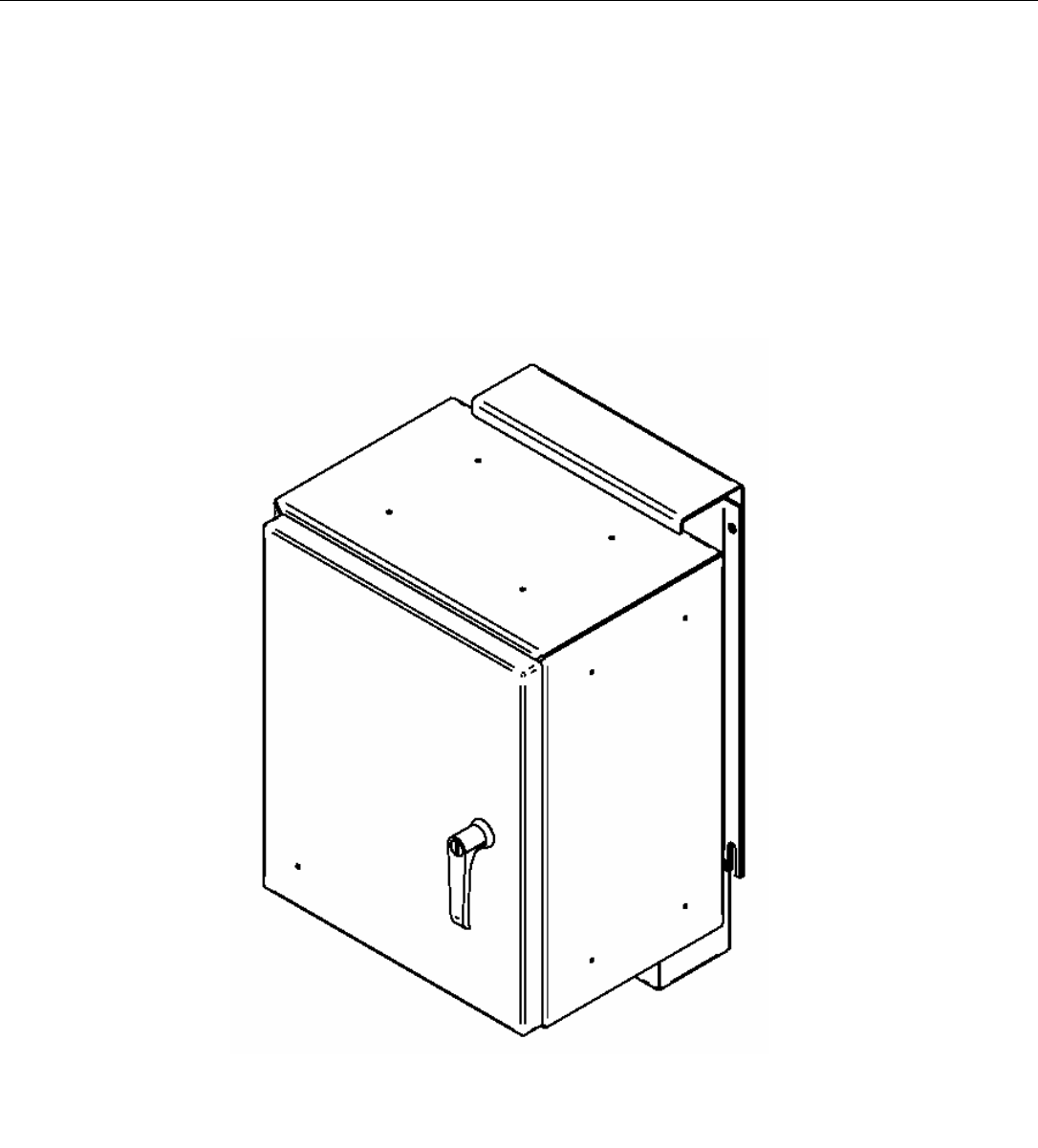
repeater is contained in a weatherproof outdoor NEMA 4 enclosure, as shown in
Figure 1. It may be used as a simple and inexpensive alternative to a base station
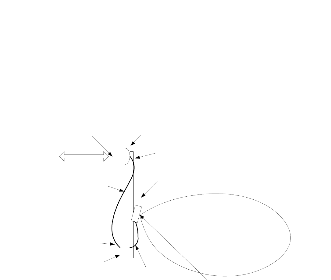
(BTS). The block diagram in Figure 2 shows a typical outdoor installation.
Figure 1: MirrorCell II Repeater Exterior View
EMS Wireless Operator’s Manual
MirrorCell II CDM 812, CDM1912 Series
608112-1, Rev C
14
Additionally, it can be configured with a variety of bandpass filters, so it can be band or
channel selective. For example, the repeater can pass just one channel, a few
adjacent channels (i.e. approximately 4.5 MHz for 3 adjacent CDMA channels), or a full
15 MHz PCS band. This gives the carrier great flexibility to choose exactly which
signals are repeated. For even more flexibility, two separate (non-adjacent)
passbands within the same 800 or 1900 MHz band may be specified. For example, at
1900 MHz, E Band (UL: 1885 - 1890 MHz) and C2 Band (UL: 1895 - 1902.5 MHz)
can be repeated using one MirrorCell IITM. At 800 MHz, one repeater can pass the A
and A’’ sub-bands (UL: 824 - 835 MHz), and also pass the A’ sub-band (UL: 845.0 -
846.5 MHz), while rejecting the competitor’s B sub-band (UL: 835 - 845 MHz).
Line of Sight to
nearby BTS
MirrorCell II Repeater
Donor Antenna,
typically parabolic
dish, 25 dBi gain
Server Antenna,
typically base station
panel design, 17 dBi
gain @ 1900 MHz
-53 dBm
+39 dBm (Gain = 92
dB)
-51 dBm
-76 dBm received
signal level
Coverage Area
7/8" Coax Cable, 2 dB
loss @ 1900 MHz
+55 dBi ERP
(including 1 dB cable
loss)
Figure 2: Typical Outdoor MirrorCell II Repeater System Design

EMS Wireless Operator’s Manual
MirrorCell II CDM 812, CDM1912 Series
608112-1, Rev C
15
An alternate use of this repeater is for indoor applications. The MirrorCell II makes
great economic sense for buildings that are too large for the EkoMini repeater, but too
small to justify a fiber optic DAS (Distributed Antenna System). One MirrorCell II can
cover most typical buildings up to approximately 200,000 square feet using ½” coax
and several power dividers feeding approximately eight indoor server antennas.
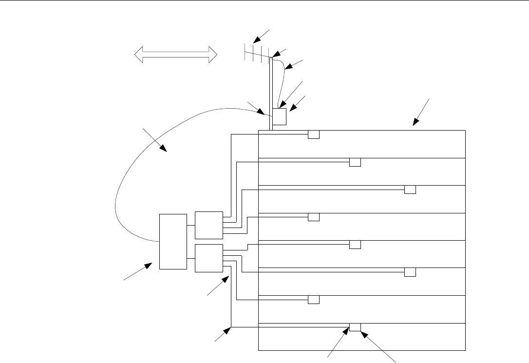
Figure 3 shows a typical example. Also, directional couplers with varying levels of
coupling values may be used to tailor the power delivered to each building floor for
optimal coverage.
The MirrorCell II has these features:
90 – 95 dB gain in a range of models with up to three composite
RF output power levels available.
Output power level may be incremented in one dB steps over a 30
dB range, either automatically with built-in software, or manually
with software commands.
An optional battery back-up unit is available to maintain repeater
operation for several hours during AC power interruptions
Receive diversity is available as an option.
EMS Wireless Operator’s Manual
MirrorCell II CDM 812, CDM1912 Series
608112-1, Rev C
16
1:4
Power
Divider
Yagi Donor Antenna, 15
dBi Gain
MirrorCell II Repeater (92 dB
Gain
8-Story Building, each
floor is 30,000 sq. ft. (175
ft. x 175 ft.)
1 Server Antenna on each
floor
Line of Sight to nearby
BTS
-53 dBm
+39.0 dBm
-52 dBm
-67 dBm received signal
strength
+37.0 dBm
+27 dBm
50 ft. 1/2" coax, 2 dB
loss @ 1900 MHz
150 ft. 1/2" coax, 6 dB loss
+21 dBm at each server
antenna
1 dB Cable Loss
1:2
Power
Divider
(3.5 dB
loss) 1:4
Power
Divider
(6.5 dB loss
each)
Figure 3: MirrorCell II Indoor Installation Example

EMS Wireless Operator’s Manual
MirrorCell II CDM 812, CDM1912 Series
608112-1, Rev C
17
2.0 Available Options
The MirrorCell II repeater is available for all Cellular 800 MHz bands (A, B, A+B, and
SMR) and PCS 1900 MHz bands (A – F). In addition, all available options are shown
in Table 1 below:
Single channel or sub-band
Two non-adjacent channels or sub-bands
+36 dBm (4 watts) composite RF output power (PCS only)
+39 dBm (8 watts) composite RF output power
+43 dBm (20 watts) composite RF output power
Wired Telephone Line Interface with Modem for Remote
Alarming
Wireless (CDMA) Data Modem for Remote Alarming
IPWMM Modem
120 - 260 VAC/50-60 Hz Operation
24 VDC Operation
Battery Back-up MPP-100 (External Unit) – non UL
Approved
Battery Back-up MPP-200 (External Unit) – UL Approved
DIN 7-16(f) Donor/Server Antenna Connectors
(Type N(f) is standard)
Receive Diversity, 1900 MHz Units
Receive Diversity, 800 MHz Units
Table 1: Available MirrorCell II Options

EMS Wireless Operator’s Manual
MirrorCell II CDM 812, CDM1912 Series
608112-1, Rev C
18
3.0 Installation Guidelines
3.1 Outdoor Site Selection
When the MirrorCell II is used outdoors, site selection is one of the most critical
decisions affecting the overall performance of the repeater system. A repeater should
be located where it can receive a sufficient line of sight signal from the donor site to
maximize the repeater’s performance. For example, supposing a 1900 MHz MirrorCell
II has +39 dBm power output specification with a gain of 92 dB. Then, an input signal
level at the donor input connector (after the donor antenna and coax cable) of greater
than or equal to –53 dBm (composite power) is required for +39 dBm output: -53 dBm
+ 92 dB gain = +39 dBm.
Examples of repeater and accompanying antenna locations include, but are not limited
to:
The roof of a building adjacent to the desired coverage area with the antennas
mounted to the penthouse or building sides
The top of a hill that is obstructing the donor site’s coverage, with the antennas
pipe-mounted at ground level
A water tower with antennas mounted at the top
An existing utility pole, with equipment and antennas mounted below any existing
power lines
A newly installed pole or tower
3.2 Donor and Server Antenna Selection
Proper selection of the repeater’s donor and server antennas is crucial in designing the
repeater system. The most important parameter to be concerned with is antenna
isolation. This is a measure of the ability of the donor and server antennas to avoid
receiving each other’s signals. Remember, the repeater is simultaneously transmitting
and receiving on each of the uplink and downlink frequency bands. For this to happen
successfully, the two antennas must be well isolated from each other, or excessive
signal levels from one antenna will be received by the other antenna. This sets up a
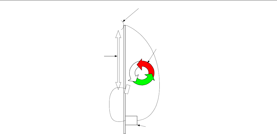
feedback loop, and oscillation begins. An example of this is shown in Figure 4 below:
EMS Wireless Operator’s Manual
MirrorCell II CDM 812, CDM1912 Series
608112-1, Rev C
19
Reflector (Dish) Donor
Antenna
Sectorized Panel Server
Antenna
MirrorCell II Repeater,
Gain = 90 dB
Antenna Isolation + cable
loss = 85 dB
Oscillation occurs because
the repeater gain is more
than the antenna isolation
plus the cable attenuation.
Figure 4: Example of Repeater Oscillation
Good antenna characteristics, especially front-to-side and front-to-back ratio, help to
provide proper isolation between the server and donor antennas. Proper antenna
mounting location is also a key to achieving adequate antenna isolation.
The isolation between antennas must be at least 10 – 15 dB greater than the gain
setting of the repeater or the repeater could go into oscillation. Antenna isolation limits
the amount of repeater gain that can be used. Therefore, if the isolation is 90 dB, the
repeater gain should be set no higher than 80 dB to ensure proper operation.
Antenna isolation can be approximately estimated with a few calculations. Please refer
to the EMS Wireless application note “Antenna Isolation Calculations” for details.
Also, a small chart titled “Isolation Examples” shows four example installations using
specific antenna models, with the resulting calculated isolation for each.
The donor antenna selection is critical in the design of a properly functioning repeater
system because it provides the majority of the required front-to-side ratio. The donor
antenna is typically a high gain antenna, with excellent sidelobe and backlobe
suppression. Microwave dish (reflector) antennas with vertical and horizontal beam
widths of less than 15 are ideal candidates for the donor antenna. This is because the
repeater should only re-transmit signal from one base station, generally chosen

EMS Wireless Operator’s Manual
MirrorCell II CDM 812, CDM1912 Series
608112-1, Rev C
20
because it has adequate signal strength and enough unused capacity to accommodate
the repeater system.
In many urban environments, base stations are physically close together. The donor
antenna must have a narrow beamwidth so it receives and transmits signal to only the
desired BTS. Microwave dish antennas also provide the recommended front-to-back
ratio of more than 25 dB to help achieve the required antenna isolation.
Even better donor antenna front-to-side ratio is available with “high performance” or
“ultra high performance” reflector antennas. These models have a metal shroud
extending out from the face of the reflector. The inside of the shroud is covered with
microwave absorbing material to suppress side radiation. The best performance
models extend the shroud and use the highest quality absorbing material.
Unfortunately, this increases the wind loading of the antenna and requires a heavier
duty support structure. The trade-off is extremely high front-to-side ratio (frequently
40-55 dB), which allows close physical spacing between the donor and server antenna.
This close physical spacing (sometimes less than 40 feet) is excellent in areas with
stringent zoning requirements that limit the structure height.
The server antenna should provide the desired coverage and also provide the
recommended front-to-side ratio of 25 dB. Many different types of antennas will work
as a server, such as panel antennas, Yagi antennas, and, for indoor applications,
omni-directional antennas.
The installer should use these specific ways to achieve proper isolation:
Use high gain, directional antennas with low sidelobes. This means the front-to-side
ratio should be better than 25dB. Also, use antennas with excellent antenna front to
back ratio.
Point the donor and server antennas opposite each other; i.e., at 180 from each
other, and ensure that the antennas have minimal backlobe radiation.
Physically separate the antennas, either vertically or horizontally.
Use external shielding, such as wire mesh or a grounded metal plate placed
between the antennas. Reflector antenna manufacturers sell ice shields, normally
used to prevent ice from falling on the antennas during winter weather. They can
also be used to enhance isolation because they are metallic fence or mesh material.
The isolation can be frequently improved by about 10 to 20 dB by using an ice
shield.

EMS Wireless Operator’s Manual
MirrorCell II CDM 812, CDM1912 Series
608112-1, Rev C
21
For indoor installations, achieving adequate isolation is still important, but somewhat
easier to achieve. This is because the donor and server antennas are physically
separated by the building material, which is normally quite lossy to RF. This is
especially true if the donor antenna is placed on a building roof that has a metallic
layer. In most of these installations, inexpensive yagi donor antennas can be used.
The server antenna(s) are frequently ceiling mount designs with most of the radiation
directed down toward the building floor. This further enhances the isolation.
3.3 Antenna Mounting and Isolation Measurements
Use the following steps to mount the donor antenna.
1. Mount donor antenna at the initial desired location. A visual line of sight path to
the BTS is critical for a strong, stable donor signal that is a constant level over a
long period of time.
2. Measure the received signal strength from the donor site. The amount of power
the repeater can produce is dependent on this signal level.
3. If greater signal strength is needed, try raising the donor antenna’s height, or
use a higher gain antenna, if possible.
4. Measure the RF channel strength received at the donor antenna and verify that
the proper base station sector is being received. The RF channel of the desired
base station should be at least 15dB higher than any of the other received RF
carriers. This can be measured using a spectrum analyzer. If necessary, the
donor antenna should be oriented until the desired RF channels are 15dB greater
than any others received. If this cannot be achieved, use an antenna with higher
gain. This means the antenna beamwidth is narrower, which requires greater
precision to physically orient the antenna toward the donor site. But, the donor
signal will be higher, and the antenna will be more effective rejecting unwanted
signals.
Then, isolation measurements should be made to ensure proper operation of the
repeater. Isolation measurement can be accomplished easily by following the
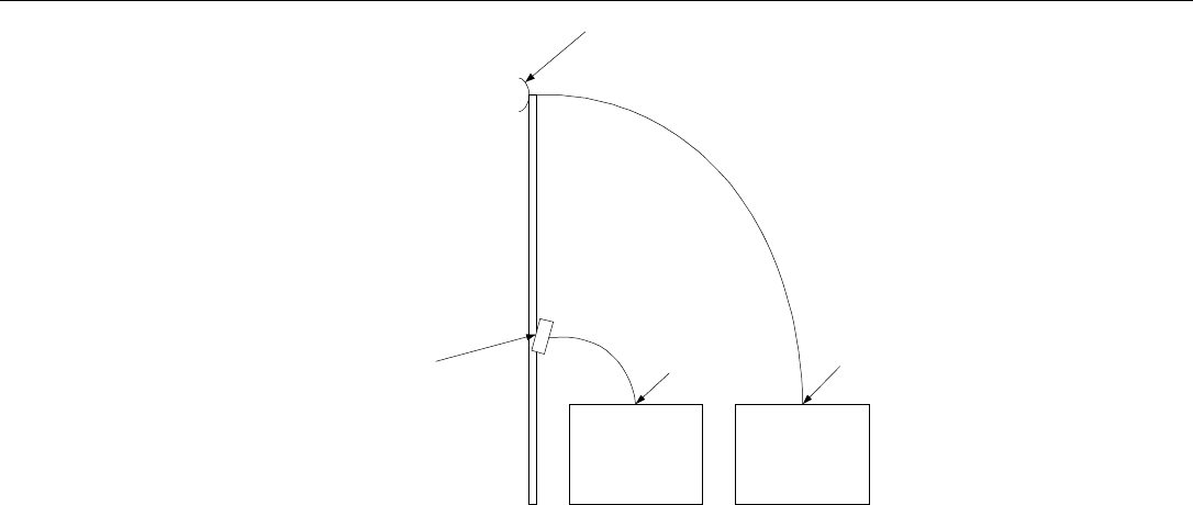
procedure outlined below, as illustrated in Figure 5.
EMS Wireless Operator’s Manual
MirrorCell II CDM 812, CDM1912 Series
608112-1, Rev C
22
Reflector (Dish) Donor
Antenna
Sectorized Panel Server
Antenna
Signal Generator,
approx. 1 watt
output (+30 dBm)
Spectrum
Analyzer
+30 dBm -70 dBm
Isolation = +30 dBm - (-70
dBm) = 100 dB
Figure 5: Antenna Isolation Measurement Set-up
1. Mount the server antenna at the initially chosen location to obtain the desired
coverage.
2. Inject a known signal within the bandwidth of operation into the server antenna. An
unused channel within the band should be used. The signal should be at least 1
watt to allow for an accurate measurement of isolation. If a 1 watt (+30 dBm) test
source is not available, the repeater and a low-power signal generator can be used
in series to generate a signal of sufficient strength. The repeater will add
approximately 60 – 90 dB of gain, depending upon the repeater model, and how
much attenuation is added to the repeater.
3. Connect a signal measurement device, such as a spectrum analyzer, to the donor
antenna. Measure the received signal level. The RF power difference between the
output of the signal generator and the input to the spectrum analyzer is the antenna
isolation. (Note that the gain of each antenna is not used in the calculation.) This
test should be done once using downlink frequencies and once using uplink
frequencies. Generally both measurements will be similar, but as much as 10 dB
difference can occur. The final result should be the lower of the two measured
values.
Antenna isolation should be measured once the donor and server antennas have been
mounted at their initially desired location. Isolation measurement is important in
properly setting up a repeater. Although isolation can be approximately calculated, an
actual measurement is strongly recommended in most applications.

EMS Wireless Operator’s Manual
MirrorCell II CDM 812, CDM1912 Series
608112-1, Rev C
23
The repeater gain must be set to at least 10 dB below the measured isolation. For
example, if the measured antenna isolation is 90dB, the repeater gain should be set for
no more than 80 dB.
3.4 Repeater Mounting
These recommendations should be followed for best repeater performance:
The repeater should be mounted so the heatsink avoids direct sunlight. This will
help improve the lifetime of the repeater.
The repeater must be mounted upright so that the connectors are on the
underside. This will help prevent a buildup of moisture inside the repeater.
The repeater is equipped with N female (optionally, DIN 7-16) antenna
connectors. Connectors are located at the bottom of the unit.
Ensure that adequate room has been allocated for the bending radius of the
cables. Refer to the cable manufacturer’s specifications for the allowable cable
bend radius.
Ensure that adequate room is allowed for the opening and closing of the repeater
door. See the specification table for dimensions of the repeater.
4.0 Repeater Set-up
Refer to the Installation Guide for instructions on mounting and connecting power
to the MirrorCell II.
Connect the Donor antenna to the “Donor” port on the MirrorCell II.
Connect the Server antenna to the “Server” port on the MirrorCell II.
DO NOT TURN THE POWER ON UNLESS BOTH DONOR AND SERVER
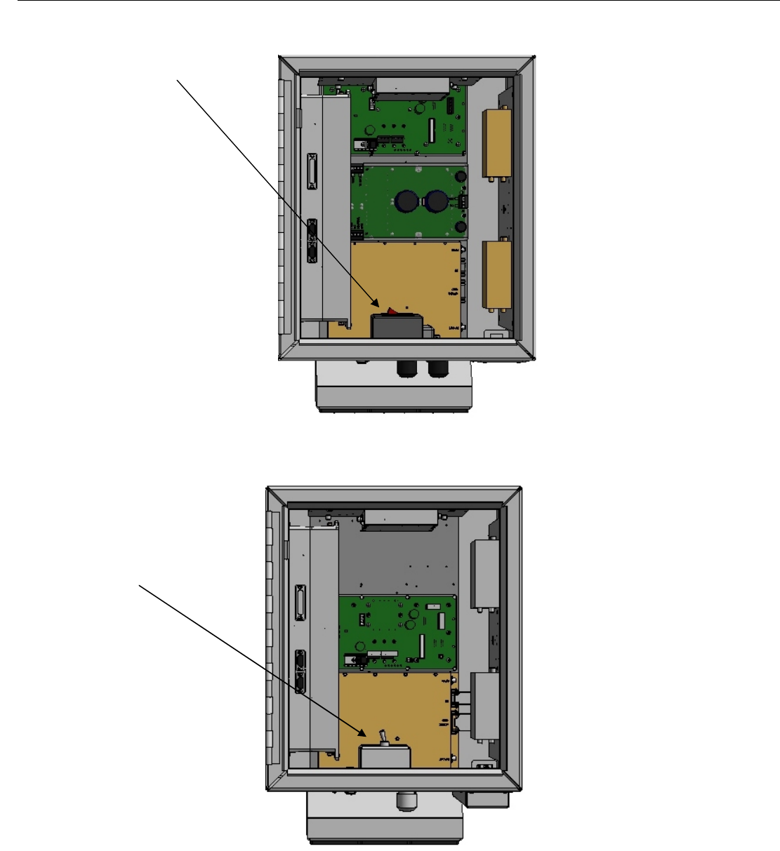
PORTS ARE TERMINATED! Turn the MirrorCell II on with the power switch
located on the inside bottom of the repeater cabinet, shown in Figure 6 below.
EMS Wireless Operator’s Manual
MirrorCell II CDM 812, CDM1912 Series
608112-1, Rev C
24
Figure 6a: Repeater Power Switch Location, A/C Version
Figure 6b: Repeater Power Switch Location, DC Version
Power Switch
Power Switch
EMS Wireless Operator’s Manual
MirrorCell II CDM 812, CDM1912 Series
608112-1, Rev C
25
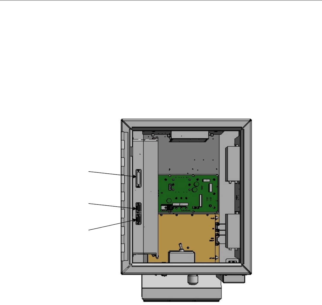
Connect a laptop computer with a terminal emulator program (i.e.,
HyperTerminal, ProComm, etc.) to the MirrorCell II RS232 port with a DB9
straight-through serial cable, as shown in Figure 7 below. The male connector is
attached to the repeater port and the female connector is attached to the laptop’s
RS232 serial port.
Figure 7: RS232 Port Location
Start the terminal program with settings 9600-8-N-1 and initialize the login by
pressing ‘enter’. Details of the terminal program configuration are shown in
Appendix A of this Operator’s Manual. Login to the repeater with your username
and password. The default username and password are “USERNAM1” and
“PASSWRD1” respectively, without the quote marks. Note that all software
commands are CASE SENSITIVE. Section 6 of this Operator’s Manual details
Interconnect
Mobile Phone
RS232
EMS Wireless Operator’s Manual
MirrorCell II CDM 812, CDM1912 Series
608112-1, Rev C
26
all the software commands available in the repeater.
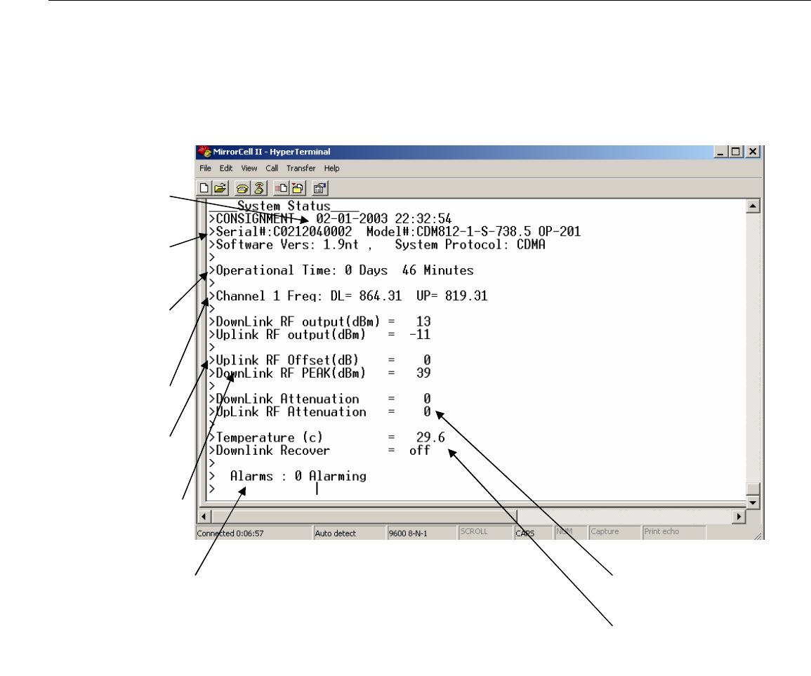
Type ‘STATUS’ and press ‘enter’ to verify the current repeater settings. Also, the
‘STATUS’ command can be used after every software parameter is changed to
verify the current setup. The screen should appear similar to Figure 8 below.
Figure 8: Status Screen
The UL and DL passband center frequencies are normally preset at the factory.
However, they can be changed by the user, if, for example, the user requires
greater attenuation of adjacent out of band frequencies.
To set the peak limit for the unit type ‘SET PEAK #’, where ‘#’ is any number
between 18 and the repeater’s maximum rated output power in dBm plus 1.
(Example: To limit the peak power to +27 dBm, type ‘SET PEAK 28’.) The
default factory setting is the repeater’s maximum rated output power plus 1. If
maximum power is desired, then skip this step.
System
Date/Time
Repeater Serial
and Model
Automatic Time
Log
DL and UL
Passband
UL RF Gain Offset
Relative to DL Gain
Peak DL Power Level
with all channels driven
Alarm
Condition
DL and UL
Attenuation Settings
Repeater Internal
Temperature

EMS Wireless Operator’s Manual
MirrorCell II CDM 812, CDM1912 Series
608112-1, Rev C
27
The automatic setup can be started by typing ‘RESTART’. The repeater will go
through the setup routine to achieve the peak limit output power as set above.
This can take up to a minute to complete and will display a message when it is
complete.
A complete list of alarms and their respective alarm code numbers is shown in
Appendix B.
The use of external alarms for the MirrorCell II is detailed in Appendix C.
Important Notes:
The MirrorCell II repeater will attempt to set itself to the PEAK limit output power
setting using its available gain. If input (donor) signal is insufficient to reach the
output power PEAK setting with the repeater’s available gain, the repeater will
remain set using the maximum gain to an output power level of
(INPUT SIGNAL LEVEL) + (REPEATER MAX GAIN) = (OUTPUT POWER
LEVEL)
If the repeater is to be moved from its current location to a new location, it is
recommended that you manually set the attenuation values to maximum (30 dB)
before turning it off.
Ensure that all RF connections remain watertight and mechanically secure.
5.0 System Optimization
The repeater uses highly selective Surface Acoustic Wave (SAW) bandpass filters,
which have a group delay of 3 microseconds. Since the propagation delay of free
space is 5.4 microseconds per mile, the delay is “equivalent” to somewhat more than
½ mile of free space propagation.
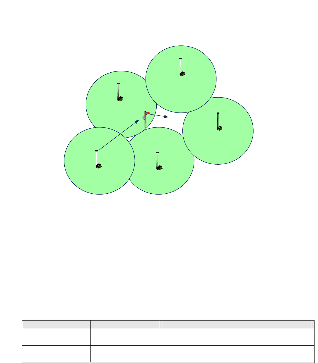
The neighbor lists of the donor base station and the base stations surrounding the area
served by the repeater may need to be adjusted after the repeater is installed. For
example, in Figure 9, a repeater extends the coverage of BTS1 to a new area. BTS1
is now a neighbor with BTS4 and BTS5, whereas without the repeater, BTS1 is a
EMS Wireless Operator’s Manual
MirrorCell II CDM 812, CDM1912 Series
608112-1, Rev C
28
neighbor with just BTS2 and BTS3. Thus, BTS4 and BTS5 must be added to BTS1’s
neighbor list, and BTS1 must be added to BTS4’s and BTS5’s neighbor lists. A drive
test of the coverage area should be performed to verify the final setup.
6.0 Detailed Software Commands
6.1 User Names and Passwords
The repeater login sequence begins by asking for Username and Password. The
MirrorCell II allows for four different user names and passwords, each of which has
different authorities. The default login parameters are shown in Table 2 below.
User Name Password Authority
USERNAM1 PASSWRD1 read/write
USERNAM2 PASSWRD2 read/write
USERNAM3 PASSWRD3 read only
USERNAM4 PASSWRD4 read only
Table 2: User Names and Passwords
BTS 1 BTS 3
BTS
4
COVERAGE
AREA
REPEATER
BTS 2
BTS
5
Figure 9: Neighbor List Changes with Repeater Operation

EMS Wireless Operator’s Manual
MirrorCell II CDM 812, CDM1912 Series
608112-1, Rev C
29
Note: The Usernames and Passwords should be changed during installation.
For example, to change a Username and Password:
SET UID# [username] <enter>
SET PWD# [password] <enter>
6.2 Basic Commands
The basic repeater commands are listed below.
STATUS Displays Status Screen
RESTART Begin Auto Setup Process
MODEM Displays Modem Configuration Parameters
GET PASSWORD Displays a list of User Names and Passwords (USRS 1
and 2)
LOGOUT Exits or Logs off repeater
EXIT Exits or Logs off repeater
GET LOG Displays Log
ALARMS Displays List of Current alarms and Trigger timestamp
ALARM # Displays Alarm #’s Parameters (1-20)
LIST ALARMS Displays a list of all alarms their assigned number and
status
NEED UPDATES Logs user off terminal and Dial out to MUM to get all
settings for the site. Used when replacing a unit in the
field, or repeater parameters has already been setup at
the MUM
6.3 “Set” Commands
The “Set” Commands allow the user to change specific parameters that define the
repeater operation:
SET UL OFFSET Up Link Gain Offset (0-16)
SET DLPOWER Desired Down Link Power Setting (17-36)
SET PROTOCOL System Technology (CDMA, AMPS, GSM)
SET PEAK Maximum Down Link Output Power (18-42)
SET PWD# Password for User ID # (8 alpha-numeric)

EMS Wireless Operator’s Manual
MirrorCell II CDM 812, CDM1912 Series
608112-1, Rev C
30
SET UID# User Name for User ID # (8 alpha-numeric)
SET DT Date in mm/dd/yy format
SET TM Time in 24hr format hh:mm:ss
SET ID Unit ID or Name
SET MUMNUMBER Phone Number to Dial to MUM when Report Active
SET UNTNUMBER Phone number of the Mirror Cell Unit.
SET REPORT Report Alarms (ON or OFF)
SET ALARM # Alarm # active or disabled (ON or OFF)
SET HB PERIOD Time between Expected Contact 0=HB off (0-999)minutes
SET ALRM RTRY Number of retries to send alarms. (0-100)
SET ALRM INTV Minutes between Alarm report retries.
SET DL FREQ # (Freq) Sets down link center frequency of the band pass
SET UP FREQ # (Freq) Sets uplink center frequency of the band pass
SET DL ATTN # Sets down link attenuation to a specified level
SET UL ATTN # Sets up link attenuation to a specific level
The example below shows how to set the repeater DL and UL passband center
frequencies (this example assumes that OPT-2 offering two non-adjacent operating
bands has been installed):
Example >set dl freq 1 1975.00
>set up freq 1 1895.00
>set dl freq 2 1947.50
>set up freq 2 1867.50
Note: ‘SET UL ATTN #’ and ‘SET DL ATTN’ commands override the auto setup
feature and allows the repeater to be set up outside of the RF detected power range of
the repeater. Peak power limit will still function properly at the lowest usable level of
detection (+18 dBm typical). The user may wish to disable down link power detect
alarm which will be on constantly due to no RF detected.
The RF detector has typically a dynamic range of detection of 23 dB and factory is
calibrated in the factory for a RF power range of +17 to +40 dBm. The software look
up table for the RF detector gives the unit a very accurate means of measuring
average RF output power, typically +/-1 dB across the power range. Greatest
accuracy is in the higher power ranges between +30 to +40 dBm.

EMS Wireless Operator’s Manual
MirrorCell II CDM 812, CDM1912 Series
608112-1, Rev C
31
The following “set” command example illustrate a typical log in session:
Command Examples
>set ul offset 2
>set dlpower 34
>set protocol CDMA
>set peak 37
>set PWD2 pass2
>set UID2 user2
>set dt 20/02/01
>set dt 02/20/01
>set tm 11:47:00
>set id unit123
>set mumnumber 9876543211
>set untnumber 1234567890
>set report on
>set alarm 1 off
>set hb period 21
>set alrm rtry 2
>set alrm intv 5
7.0 Technical Description
General Description
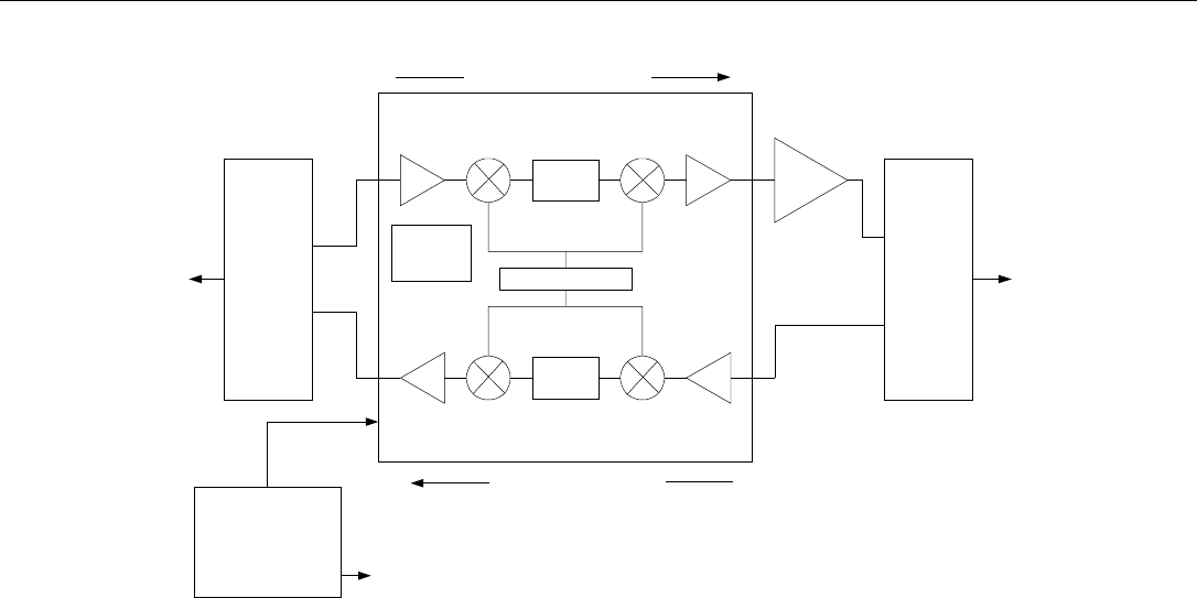
The block diagram in Figure 10 shows the major components of the MirrorCell II.
EMS Wireless Operator’s Manual
MirrorCell II CDM 812, CDM1912 Series
608112-1, Rev C
32
Duplexer DuplexerSynthesizer
Downlink Power Amplifier
Donor
Antenna
Server
Antenna
LNA
Downconverting
Mixer
Downconverting
Mixer
Upconverting
Mixer
Upconverting
Mixer
SAW
Bandpass
Filter
SAW
Bandpass
Filter
Uplink Output
Amplifier
LNA
Downlink
Amplifier
Downlink (Forward) Signal Path
Uplink (Reverse) Signal Path
UL
DL
UL
DL
Channelizer Unit
Power Supply
Status and
Control
Module
Power Source (120 VAC,
200-260 VAC, 24 VDC)
Figure 10: Block Diagram of MirrorCell II Repeater
The five major modules include: The Channelizer Module, the downlink power
amplifier, power supply, duplexers, and the status and control module (contained within
the Channelizer). Built-in software adjusts and controls the repeater gain and other
functions.
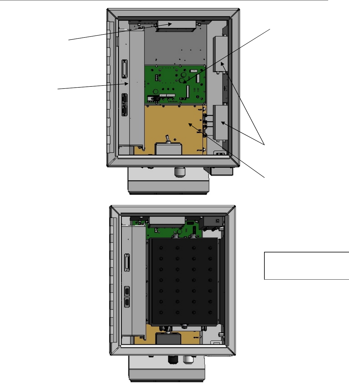
An internal view of the repeater with the major components identified is shown in
Figure 11.
EMS Wireless Operator’s Manual
MirrorCell II CDM 812, CDM1912 Series
608112-1, Rev C
33
Channelizer
Downlink Power
Amplifier
Duplexers
DC Interconnect
Module
Receive
Diversity LNA
Full PCS Duplexer
Installed

EMS Wireless Operator’s Manual
MirrorCell II CDM 812, CDM1912 Series
608112-1, Rev C
34
Figure 11: MirrorCell II Internal View
The repeater is enclosed in an aluminum case with rear mounted cooling fins.
Aluminum offers a lightweight design with good heat conduction and weatherproof
protection. The housing conforms to the NEMA (weather-proof) standard. Per the
NEMA 4 specification, the enclosure will withstand 65 PSI (pounds per square inch)
pressure salt water spray on all four sides with no leakage to the inside.
The unit is cooled with electric fans that are cycled depending on the internal
temperature of the unit. Forced air from the fans is directed between cooling fins on
the rear of the cabinet, which enhances the MTBF by as much as 100%.
The transmit and receive antenna ports are standard N-type (DIN 7-16 optional)
located on the underside of the repeater.
7.2 Channelizer Module
The primary reference frequency for the MirrorCell II repeater is provided by a 20
MHz temperature stabilized crystal oscillator. This basic reference frequency is used
by the PLL to generate the local oscillator (LO) frequency. The 20 MHz frequency
accuracy is 5 ppm. All internally generated frequencies are locked to this basic
oscillator. The same LO frequency is used for both the up converter and down
converter, ensuring no difference in the input and output frequencies.
The downlink and uplink paths in the channelizer module each consist of an LNA, a
down-converting mixer with a low side Local Oscillator that produces a 140 MHz
Intermediate Frequency (IF). Then, SAW (Surface Acoustic Wave) filters, an up-
converting mixer, and a post amplifier complete the circuit. The channelizer module
also includes power level control functionality. Note that the uplink path includes the
power amplifier in the Channelizer unit, while the downlink path has the power amplifier
external to the channelizer.
7.3 Downlink Power Amplifier
The downlink power amplifier may have output power levels as shown in Table 1. The
power amplifiers are designed to meet industry standards regarding Adjacent Channel
Power Ratio (ACPR) and spectral re-growth.

EMS Wireless Operator’s Manual
MirrorCell II CDM 812, CDM1912 Series
608112-1, Rev C
35
7.4 Power Supply Module
The power supply is designed for an input voltage of 120 VAC, 200-260 VAC, or +24
VDC, depending on the option. A surge suppression filter is included for voltage
transient protection on the A/C powered models.
7.5 Duplexer Filters
The uplink and downlink RF signals are separated and combined with duplexers
operating in the appropriate frequency bands. The duplexers are constructed with
comb-line cavity bandpass filters, which provide excellent isolation against out-of-band
signals.
7.6 Status and Control Module
The status and control module, contained within the channelizer, enables monitoring
and control of the repeater. This module determines the status of the Channelizer and
identifies failure conditions. When a failure condition is identified, an alarm is issued.
When this occurs, the module sends a message to a PC over a serial data link
(modem). Also, the optional MUM software program, which is installed on a remote
computer, can monitor these alarms, and query the repeater on a pre-determined
schedule.
7.7 Automatic Software-Driven Gain Control
A key feature of the MirrorCell II repeater is the automatic software-driven gain
control, or more simply, Automatic Set-up. This allows “plug and play” operation with
little or no user intervention. When Automatic Set-up is initialized, built-in software
adjusts the internal attenuators in the uplink and downlink signal paths within the
Channelizer module. Note that the UL and DL gains are generally equal to ensure a
balanced path, unless the user manually changes them or the uplink signal is too high.
For most applications, the automatic software sequence will set an appropriate gain
value without manual intervention.
The following software sequence is used:
The repeater gain and attenuator settings can be reset by using the ‘RESTART’
software command, as described in section 4. This re-starts the software
sequence and initiates Automatic Set-up.

EMS Wireless Operator’s Manual
MirrorCell II CDM 812, CDM1912 Series
608112-1, Rev C
36
When Automatic Set-up is initiated, variable attenuators are immediately set at
their maximum values of 30 dB. Thus, the UL and DL gain is 30 dB below the
specified value. This prevents the repeater from exceeding its maximum power
output specification in non-ideal installation situations.
A power sensor measures the downlink signal level at the server output. If this
level is below the maximum output specification, or ‘PEAK’ level, the software
removes UL and DL attenuation in 1 dB steps until one of two things occurs:
o The ‘PEAK’ level is achieved. In this case, the donor signal is sufficient for
the repeater to achieve is ‘PEAK’ setting without using its full gain.
o All the attenuation is removed. In this case, the donor signal is too low for
the repeater to achieve its ‘PEAK’ setting with its available gain.
If the donor signal level increases later (i.e. more channels are added), causing
the repeater to exceed its ‘PEAK’ setting, the software will automatically add
attenuation to keep the repeater within specification.
If the donor signal level decreases later, the repeater will not remove attenuation
to boost the repeater output to its original level. That is, the software will only
add attenuation, but never remove it. This action differentiates this control
system from simple AGC systems. Normally, a base station and a handset
already have a power control system in place. The repeater gain does not
continuously change to maintain its ‘PEAK’ setting, as this would fight and defeat
the BTS power control function.
8.0 Technical Specifications
The MirrorCell II specifications are divided into RF (Table 3), Electrical (Table 4)
Mechanical (Table 5), and Environmental (Table 6), shown below.
Parameters Uplink Downlink
Frequency – Models:
800 MHz:
Cellular A (A’’ + A)
Cellular B (B + A’ + B’)
Cellular AE (A’’ + A + A’
[Excludes B])
Cellular BE (B + B’
[Excludes A’])
Cellular Full Band
Public Safety
ESMR
ESMR Full
1900 MHz:
824 – 835 MHz
835 – 849 MHz
824 – 835 MHz, 845 –
846.5 MHz
835 – 845 MHz, 846.5 –
849 MHz
824 – 849 MHz
821 – 824 MHz
806 – 821 MHz
806 – 824 MHz
869 – 880 MHz
880 – 894 MHz
869 – 880 MHz, 890 –
891.5 MHz
880 - 890 MHz, 891.5 –
894 MHz
869 – 894 MHz
866 – 869 MHz
851 – 866 MHz
851 – 869 MHz

EMS Wireless Operator’s Manual
MirrorCell II CDM 812, CDM1912 Series
608112-1, Rev C
37
PCS A
PCS B
PCS C
PCS D
PCS E
PCS F
1850 – 1865 MHz
1870 – 1885 MHz
1895 – 1910 MHz
1865 – 1870 MHz
1885 – 1890 MHz
1890 – 1895 MHz
1930 – 1945 MHz
1950 – 1965 MHz
1975 – 1990 MHz
1945 – 1950 MHz
1965 – 1970 MHz
1970 – 1975 MHz
Bandwidth of Bandpass 800 MHz Models: 200
kHz – 14 MHz
1900 MHz Models: 200
kHz – 15 MHz
800 MHz Models: 200
kHz – 14 MHz
1900 MHz Models: 200
kHz – 15 MHz
Composite Output Power
Maximum Limit
+23dBm +/- 1 dB (200
mW) +33 dBm +/- 1 dB (2W)
+36 dBm +/- 1 dB (4W)
(1900 MHz only)
+39 dBm + 0.5/-1.0 dB
(8W)
+43 dBm + 0.5/-1.0 dB
(20W)
Gain at Minimum Attenuation:
800 MHz:
1900 MHz:
+36 dBm (4W) option
+38.5 dBm (7W) option
+43 dBm (20W) option
(see next page)
90 dB Nominal for any
power output option
90 dB Nominal
92 dB Nominal
95 dB Nominal
(see next page)
90 dB Nominal for any
power output option
90 dB Nominal
92 dB Nominal
95 dB Nominal
Gain Range 30 dB 30 dB
Gain Flatness 2.5 dB pk to pk 2.5 dB pk to pk
Gain Change over temperature +/- 2 dB +/- 2 dB
Gain Step Size 1 +/- 0.5 dB 1 +/- 0.5 dB
Gain change over BW +/- 2 dB +/- 2 dB
Number of Carriers Single or Multiple Single or Multiple
Noise Figure at Maximum Gain
800 MHz:
1900 MHz:
<5 dB
<5 dB
<6.5 dB
<6.5 dB
Spurious Output FCC/IC FCC/IC
Number of Bandpasses or
Channels 1 or 2, depending on
option 1 or 2, depending on
option
Signal Electrical Delay 3 sec (Typical) 3 sec (Typical)
Connectors N(f) Standard, DIN 7-16
Optional N(f) Standard, DIN 7-16
Optional
Mean Time Between Failures
(MBTF) 75,000 hours 75,000 hours
Table 3: MirrorCell II RF Specifications

EMS Wireless Operator’s Manual
MirrorCell II CDM 812, CDM1912 Series
608112-1, Rev C
38
RF Output Power Current and Power Requirement
120 VAC Power
Option 220 VAC Power
Option 24 VDC Power
Option
+36 dBm (4W)
(1900 MHz only) 3.0 amps 1.6 amps 10.5 amps
+39.0 dBm (8W)
800 and 1900 MHz 3.0 amps 1.6 amps 10.5 amps
+43 dBm (20W)
800 and 1900 MHz 4.0 amps 2.2 amps 14.5 amps
Table 4: MirrorCell II Electrical Power Specifications
Parameter Specification
Housing, (WxHxD) 15 x 24 x 14 inches (38.1 cm x 61
cm x 35.6 cm)
Weight 49 pounds (22.3 kg)
Housing Material Aluminum, off-white paint color
Cooling Convection/Forced Air
Table 5: MirrorCell II Mechanical Specifications

EMS Wireless Operator’s Manual
MirrorCell II CDM 812, CDM1912 Series
608112-1, Rev C
39
Parameter Specification
Operating
Temperature -25 to 50 C.
Storage
Temperature -40 to 75 C
Enclosure NEMA 4 (Weatherproof)
Table 6: MirrorCell II Environmental Specifications
9.0 Troubleshooting, Maintenance and Parts Replacement
9.1 Troubleshooting:
A chart of troubleshooting procedures is shown in Table 7 below.
PROBLEM POSSIBLE CAUSE SOLUTION
LED Power Supply Module is
not lit 1. Unit not turned on
2. No power to unit
3. Module failure
4. Input AC or DC wiring is
faulty.
1. Plug in/turn on unit
2. Restore power to unit
3. Replace module
4. Rewire/repair power source to
repeater.
LED on power supply module
is lit but cannot login to the
repeater
1. Software emulation program
is not set properly
2. Software emulation program
is not working properly
3. Cables not functioning
properly
4. Bad Channelizer
1. Verify program is set properly
2. Verify program is working
properly; replace if necessary
3. Replace cable
4. Replace Channelizer module
Poor reverse signal quality;
forward signal quality looks
fine
Excessive noise contribution to
BTS because gain set too high Reduce repeater gain setting
Output power too low on
forward link 1. Receiving too low of a
signal from donor site
2. Gain not set correctly
1. Verify adequate signal is
received; adjust donor
antenna if necessary
2. Reset gain
Receiving sufficient signal
strength but too much
interference to make a call
Repeater goes into oscillation
because of insufficient antenna
isolation
1. Improve antenna isolation:
Further separate antennas
Mount a shield between
antennas
2. Reduce repeater gain

EMS Wireless Operator’s Manual
MirrorCell II CDM 812, CDM1912 Series
608112-1, Rev C
40
Table 7: Troubleshooting Procedures
9.2 Maintenance
The MirrorCell II does not require preventative maintenance.
9.3 Parts Replacement
In case of repeater failure, EMS Wireless recommends you send back the entire
repeater for repair, and mount a spare repeater in its place.
EMS Wireless Operator’s Manual
MirrorCell II CDM 812, CDM1912 Series
608112-1, Rev C
41
Appendix A: HyperTerminal Configuration
HyperTerminal may be used for terminal emulation when using remote control of the
repeater. Use the following steps for setting up HyperTerminal.
1. In the Start menu, open the Programs folder. Go to the Accessories folder in the
Programs folder.
2. Choose Hyper-terminal. In that folder, choose HyperTerminal.
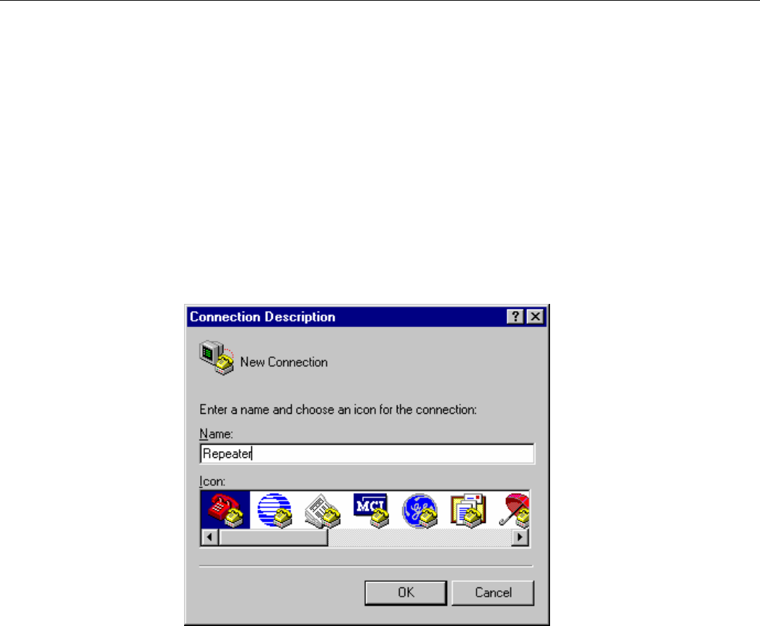
3. A dialog box will ask you to name the session. Use any name you choose. Select
the icon showing the two telephones. See Figure A-1.
Figure A-1: HyperTerminal Connection Description Window
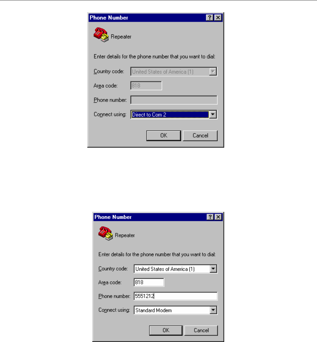
4. For a direct connection to the repeater, choose “Direct to Com X” in the drop down
box. See Figure A-2.
EMS Wireless Operator’s Manual
MirrorCell II CDM 812, CDM1912 Series
608112-1, Rev C
42
Figure A-2: HyperTerminal Screen for Direct Connection
5. For remote connection via modem, enter the number you wish to dial and choose to
connect using “Standard Modem” as in Figure A-3.
Figure A-3. HyperTerminal Screen for Modem Connection
EMS Wireless Operator’s Manual
MirrorCell II CDM 812, CDM1912 Series
608112-1, Rev C
43
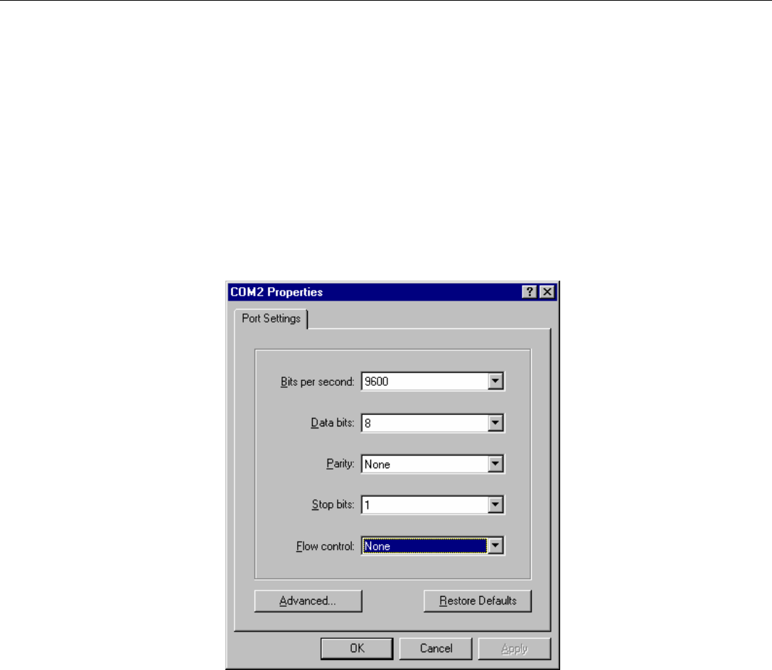
6. After clicking OK, you will need to choose “Port Settings.” Select:
Bits per Second: 9600
Data bits: 8
Parity: None
Stop bits: 1
The port settings will be the same for direct connection and remote connection. For a
direct connection to the repeater, make sure flow control is set to “None”. See Figure
A-4 below.
Figure A-4: Port Settings for Modem Connection
The MirrorCell II will auto answer on the 2nd ring. Once the modems handshake and a
session is started it may be necessary to press the <enter> key to initiate login
sequence.

EMS Wireless Operator’s Manual
MirrorCell II CDM 812, CDM1912 Series
608112-1, Rev C
44
Appendix B: Alarm Table
A complete list of alarms is shown in Table B-1 below.
Table B-1: Repeater Alarms
Alarm Number Alarm Name Alarm Status
1 SynthLock Uplink on
2 SynthLock DownLink on
3 OverTemp on
4 Fan Alarm on
5 AmpDownLink on
6 AmpUplink on
7 Low Output Pwr DL on
8 Power AC on
9 Batt Power DC off
10 Low V DC Input on
11 OverDrive Uplink on
12 Com Alarm, Heartbeat off
13 External 1 on
14 External 2 on
15 External 3 on
16 External 4 on
17 Intrusion on
18 S Param Change off
19 Invalid Logins on
20 OverDrive DL on
EMS Wireless Operator’s Manual
MirrorCell II CDM 812, CDM1912 Series
608112-1, Rev C
45
Appendix C: External Alarms
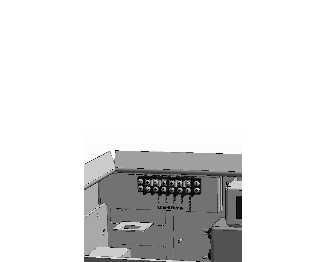
Other pieces of equipment can be alarmed by connecting relay outputs into the
external alarms of the MirrorCell II. An alarm condition will be generated when the
open collector input is pulled to common ground. The input has a very weak pullup
resister in circuit. The external alarm inputs can be physically connected either on the
alarm terminal-strip as pictured in figure C-1 or directly to the DC Distribution board on
the labeled jumper. The software should be configured to not alarm any external alarm
not physically connected to the repeater. The software alarms for the external alarms
are in order and number 13 to 16. Alarm 9 corresponds to the Batt Backup alarm input
and is used to alarm BBU systems attached to the repeater.
Figure C-1