ENGINO NET STEM70 STEM70 User Manual 05 Robotics instructions 4
ENGINO.NET LTD STEM70 05 Robotics instructions 4
UserManual.wiki
>
ENGINO NET
>
STEM70 User Manual
>
User Manual p3
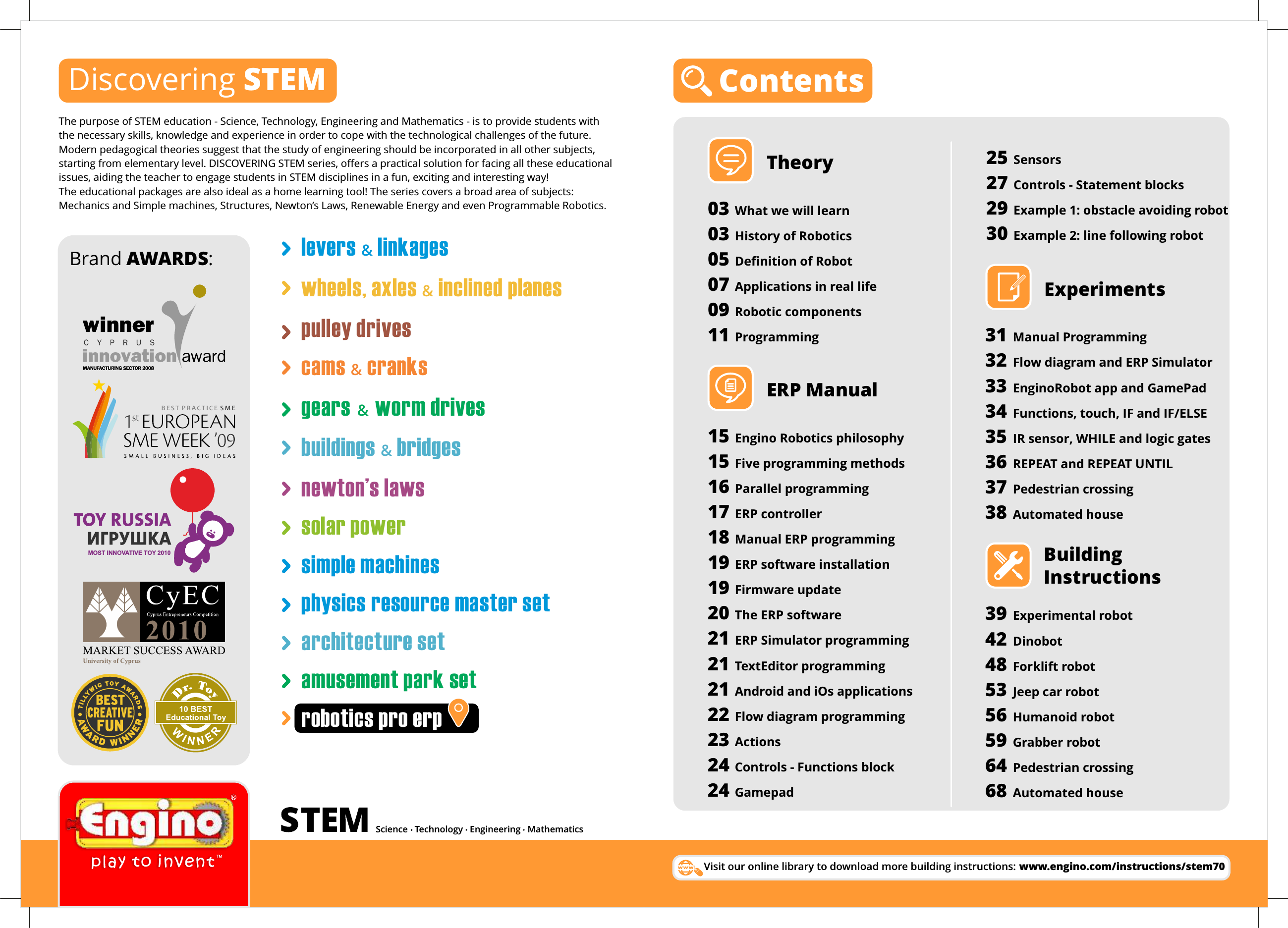
Contents
1.
Users Manual p1
2.
Users Manual p2
3.
User Manual p3
User Manual p3
Navigation menu
Upload a User Manual
Namespaces
Wiki Guide
HTML
PDF
Info
Views
User Manual
Discussion / Help
Navigation