ENGINO NET STEM70 STEM70 User Manual 05 Robotics instructions 4
ENGINO.NET LTD STEM70 05 Robotics instructions 4
Contents
- 1. Users Manual p1
- 2. Users Manual p2
- 3. User Manual p3
User Manual p3
19 20
ERP Software installation
®
The ERP can be programmed either manually or with the Engino software included in the set. Manual
programming does not apply to sensors. A machine that executes a series of commands is not a true robot; a true
robot is one that can be programmed to take its own decisions based on the feedback received from its sensors. To
®
be able to create such a program you need to install the Engino Robotics Pro 1.2 software, which can be
downloaded from the website: www.enginorobotics.com . Alternatively you can use the CD included in your
®
Engino Robotics package.
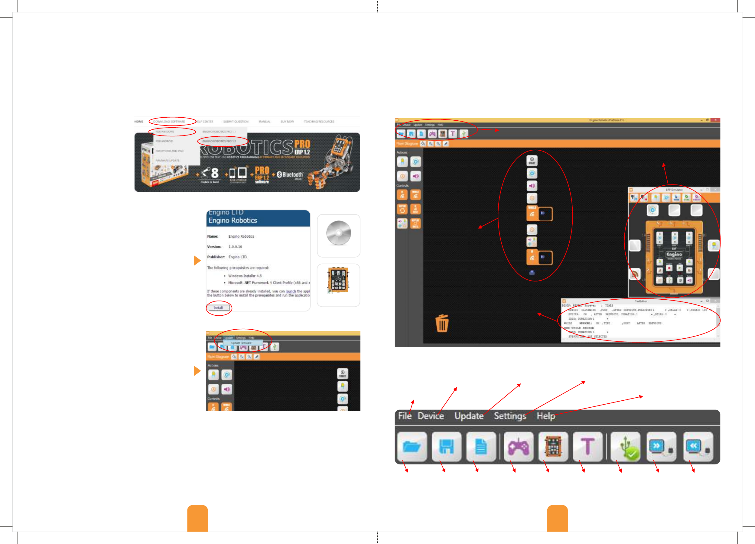
1. Go to the website
www.enginorobotics.com .
Click on the “download
software” tab and choose “for
Windows / Engino Robotics
PRO 1.2”. For Android and iOs
you can download the
EnginoRobot BT app for manual
control, but this does not offer
visual programming through the
flow diagram or the text editor.
5. Inside the ERP software of your PC, select the tab
“Update” and click “Update Firmware”. This will bring
the setup program.
6. On the pop-up window click on the “update
firmware” button. The software will seek the latest
version of the firmware online and a new window will
show up promptly with the number of the version.
Select “Yes” to continue.
7. If the upgrade is successful you will see a message
on the screen and hear a sound from the controller.
The ERP Software
“File” allows you
to create and save
a new program,
open an existing
one and exit the
application.
To update the
firmware in the
latest version you
must be connected
to the Internet.
“Device” allows you
to send a program
to the controller or
receive a program
from the controller’s
memory.
From “Settings”
you can change
the default
motor speed
and configure
the IR sensors.
Open files
to find a
saved
program
Clear the
current
work to
start new
GamePad
controller
Show/hide
the ERP
Simulator
window
Show/hide
the Text
Editor
window
Save the
current
program
Connect
with the PC
through
USB cable
Send or receive a program
between the PC and the ERP.
These two buttons show up
when the USB is activated.
Go to enginorobotics
website to download the
booklet or other teaching
material and get help in
any issue concerning
your package.
2. Click on the “Install” button.
3. In the pop-up window click on the “save” button.
4. Go to the folder “downloads” (or in other location
where your downloaded files are) and find the file
“setup.exe” . To start the installation of the ERP
software, double click the file and press the button
“RUN” in the pop-up window.
5. Once the installation is completed the software will
start automatically and a shortcut will be created on
your Desktop.
Firmware update
The ERP development team is continually upgrading
the controller’s embedded software (firmware) to fix
potential bugs and add new functions. Once you
connect your controller with the ERP software and
click the USB button, you will be informed if there is
new firmware update. For this, you need to set the
controller in DFU (Device Firmware Update) mode:
1. Turn the controller OFF by pressing the ON-OFF
button (no LED should be lit).
2. Connect the controller with the PC through USB.
3. Keep the “program” button pressed. Then press the
“ON-OFF” button once while still pressing the
“program” button. If you do this correctly, the ERP
device will be set in DFU mode with the orange and
green lights half lit.
4. Wait for a few seconds until the PC connects with
the ERP.
The patent pending ERP software consists of 3 windows: the FLOW DIAGRAM, where you can drag and drop blocks
to create a sequence of commands; the ERP SIMULATOR, where you can program the same way as you would do
manually; and the TEXT EDITOR, where you can view and edit the program in an easy to read text format.
To connect the ERP controller to your PC, place the included USB cable on the controller’s port (at the bottom) and
the other end on a USB port of the computer. Turn ON the controller by pressing the ON/OFF button and wait for a
few seconds until your PC installs the device. Then click on the USB button inside the ERP software to connect. Note
that the ERP cannot be powered by the PC through the USB cable, but only with the batteries.
setup
Engino
Robotics P....
Flow diagram
Main menu
(explained below)
ERP Simulator
TextEditor
21
ERP Simulator programming
The Simulator has the same interface as the actual
device. You can click on the buttons using your mouse
the same way as you would program the physical
device. The Simulator has some advanced features. As
it is connected real time with the other windows, a
change in one window is reflected on the others,
allowing easier editing. Important: You should first
set-up the Simulator the same way you have built
the actual robot by dragging the Motor, LED light
and Sensor icons to the appropriate ports.
Transition from ERP Simulator to Flow Diagram:
One of the great advantages of the Simulator is that it
allows you to built a program very easily simply by
clicking on the usual command buttons. If you click on
any of the buttons on the Simulator in record mode
(for example “Motor 1”) you will see that automatically
an icon is created in the Flow diagram under the START
button. If you click on another button (for example
“Led 1”) then another icon will appear under the
previous one creating a visual sequence of commands.
The icons in the Flow diagram allow the user to edit
the parameters by right clicking on each block.
Recording example 3:
Connect three motors at each of the ports A, B and C
and two LED lights at each of the ports Led 1 (port 1)
and Led 2 (port 3). Click on the “Program” button to
record and you will notice that each step is recorded
on the Flow Diagram automatically. The program you
write can then be saved or downloaded to the
controller using the file menu commands.
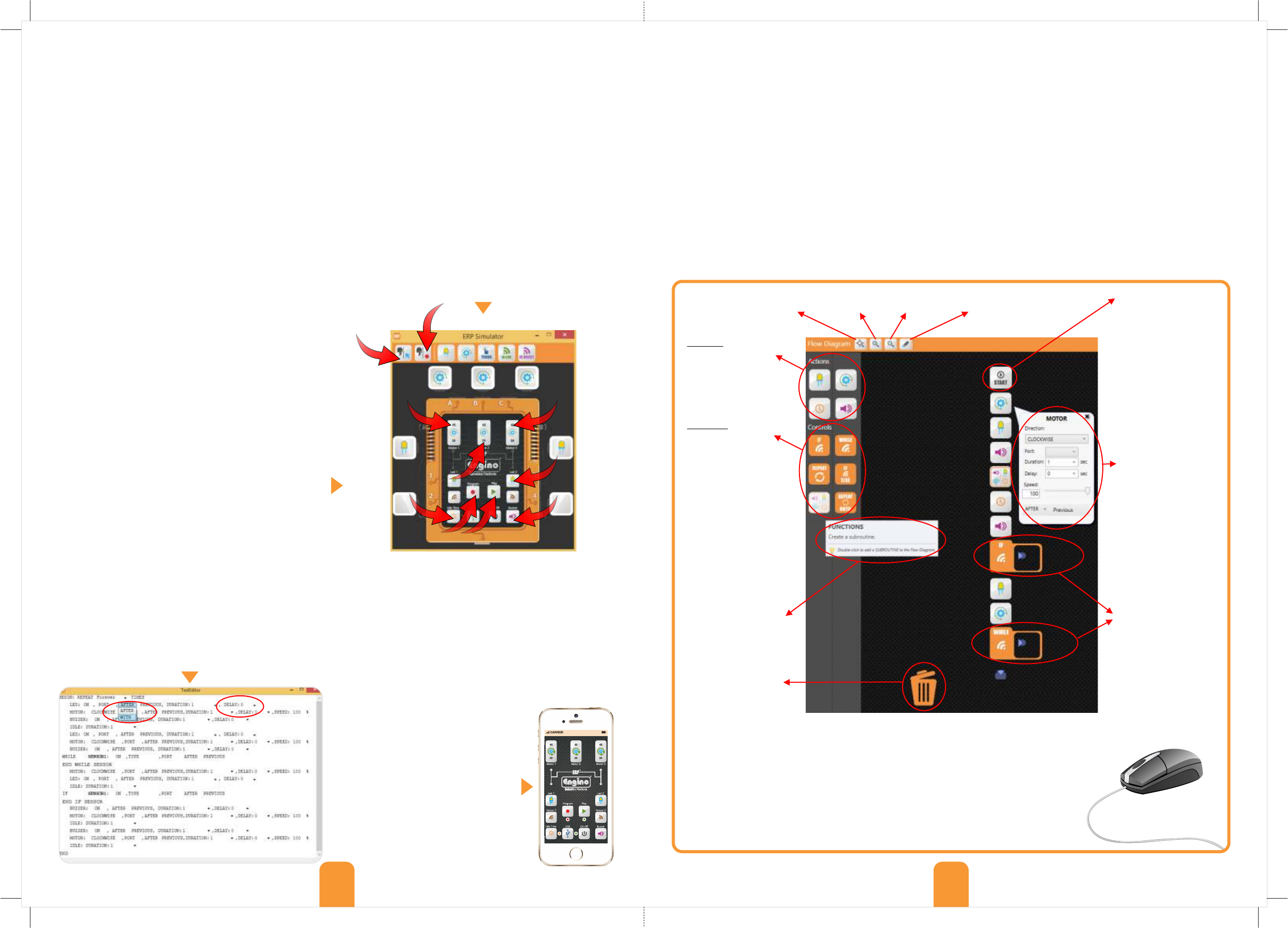
Flow diagram programming
You can use your mouse to get information and make changes in the following ways:
- Place your mouse on any icon or block in order to view descriptions and tips.
- Right-click on the blocks within the flow diagram to see and modify their properties.
- Add or change the order of blocks using the drag and drop feature.
- You can also add blocks to the flow diagram from the left side with double-click.
- To delete unnecessary blocks simply drop them into the “bin” icon.
To create a program, you can either drag the blocks
from the left side of the screen and drop them below
the “START” icon in the main window, or double-click
on the blocks. Automatically, a new space (arrow) is
created under each inserted block, so that the next
step can be added. The order of the icons determines
the sequence of the commands. With right-click on the
icons the user can change the variables of each
command, such as the port output, duration and
order (with or after previous). When the program is
completed, push the “Send program” button at the
top control panel and the program will be transferred
to the ERP controller by USB connection.
22
TextEditor programming
®
The Text Editor is a unique feature of the Engino ERP software. You can’t actually create a program from zero in the
Text Editor, however you can view and edit an already existing program written in a user friendly pseudo language.
The text commands are constructed automatically as you drag and drop icons on the Flow diagram or as you press
the buttons on the Simulator. Each line describes each block in the same order as in the flow diagram and you can
change some of the variables either from collapsing menus (e.g. choosing delay time) or by writing a value (e.g.
speed). These changes affect the flow diagram and subsequently the program.
Right-click on any
block to see and edit
its variables: e.g.
port state, direction,
delay, duration,
speed, after/with
previous. Click X (on
the top right corner)
to hide the variables’
window
Add blocks inside the
conditional
statements to create
a sequence of
commands that will
be activated once
the conditions of the
sensor are TRUE or
FALSE accordingly.
Below you can see an example of the flow diagram
with descriptions of all the variables and blocks. For
detailed explanations, read the next pages about:
- how to use the action blocks;
- the difference between delay variable and idle block;
- the After/With Previous variable;
- how to use functions to create subroutine programs;
- how to use the GamePad window;
- how to use the touch and InfraRed sensors;
- how to configure the InfraRed sensors;
- how to use the logic gates AND and OR;
- detailed explanation of two programming examples:
obstacle avoiding robot and line following robot.
Instructions:
1. Click the “Program” button.
2. Click the anti-clockwise button of the motor 1 in
port A for 1 second.
3. Click the “Idle Time” button for 2 seconds.
4. Click the “multiple select” button at the top menu.
5. Click to select the buttons of the clockwise rotation
of motor 2 in port B, the anti-clockwise rotation of
motor 3 in port C and the LED 2 in port 3.
6. Click the “multiple record” button at the top menu
for 4 seconds.
7. Click the “Buzzer” button for 1 second.
8. Click the “Send” button to upload the program to
the controller (through USB).
9. Click the “Play” button to check the program.
Android and iOs applications
Install the EnginoRobot BT app,
free of charge, available on
Google Play or Apple Store. The
application simulates the actual
ERP device. To use it, you need to
connect the controller with your
smart device through Bluetooth.
Push the “idle time” button on the
ERP when it is switched on, open
the app and connect your device
with the ERP Bluetooth network.
3
2
4
5
5
5
6
7
9
1
Actions: use these
blocks to add LED
light, motor, idle
time and buzzer
sound.
Controls: add these
blocks in order to
create a repeat
statement and if,
while, if/else, repeat
until conditional
statements. You can
also add a function
block to create a
subroutine program
which can be used for
saving a specific
sequence.
Place your mouse on
any icon to see tips
and descriptions
Drop blocks into the
bin in order to delete
them
Fit on Screen Zoom in Zoom out Clear unused blocks Right-click on the
“Start” icon to
change how many
times your program
will be repeated and
provide a
description of it.
Only blocks placed
under the “Start”
icon are part of the
program
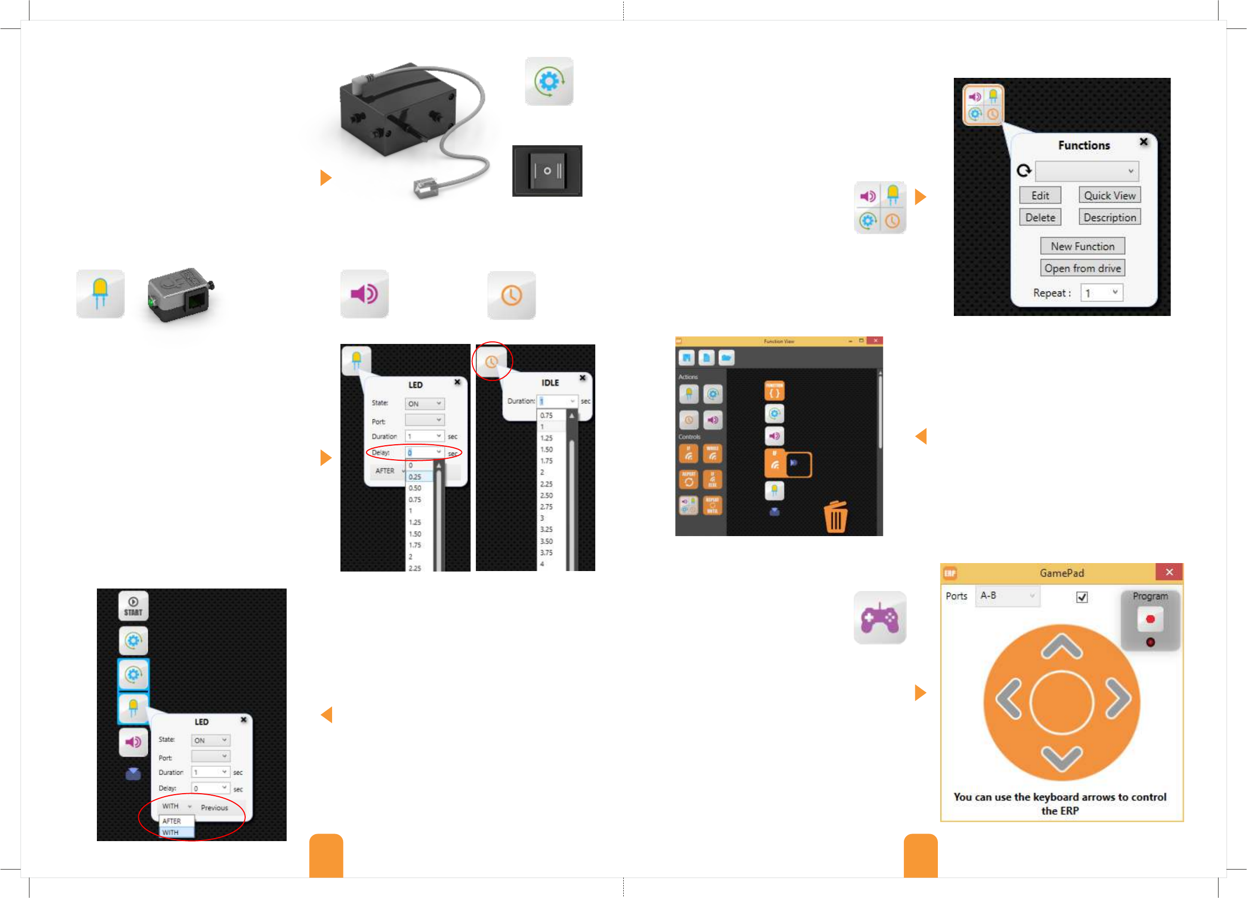
The Gamepad can be used to control two
motor ports (A, B, C) simultaneously. In
order to enable it, first connect your PC
with the robot through a USB cable and
click on the “USB” icon. Then click on the
“GamePad” icon found under the main menu. Inside
the GamePad window find the “Ports” menu and
choose the pair of ports you wish to control: A-B or B-
C or A-C. The system will lock your selection and you
can only select another pair if you uncheck the small
square. To control the robot, click on the arrows or use
the arrows on your keyboard. By clicking on the
program button you can record every step and
transfer it on the flow diagram at the same time. The
GamePad can be quite useful in situations that you
wish to put a robotic vehicle into motion in an easy
way, without thinking about the direction of rotation of
the motors (clockwise and anti-clockwise).
A function is a subroutine program with specific
sequence of commands. It is basically a program
within the program, that can be saved, edited and
repeated. Functions can be quite useful when you
want to add a routine fast e.g. wheels moving forward,
without the need of adding blocks and editing the
variables every time.
In order to add a function simply drag the
“functions” block from the left side of the
screen (under controls) inside the flow
diagram. Right-click on the block to view
its properties. You can find already saved functions in
the drop-down menu or search for them by clicking
on the “Open from drive” button. You can have a
quick view in text form of the subprogram by clicking
on the “Quick view” button or see a description you
wrote by clicking on the “Description” button.
To change the properties of a function you can click on
the “Edit” button or create a new one with the “New
Function” button. On the new pop-up window you can
find the same blocks and use it the same way as with
the main program. There is also a separate subroutine
TextEditor. Once you finish editing, you can save the
function by clicking on the save/load icon and exit the
subroutine window to get back to the main screen.
The difference between “function” and “repeat”
statement (described in the next page) is that in a
function program you can add conditional statements
(like if and while) , but in the repeat statement you can
only add action blocks and just set the number of
times they will repeat. Also, a function can be saved.
After/with previous variable
As mentioned before, Engino Robotics has created an
innovative way of parallel programming (various tasks
executed simultaneously by the robot). For this, you
can right-click on any block inside the program, thus
opening a tab with all its variables. Within this tab you
can find the “After/With Previous” variable. By default,
this variable is set as “After Previous”, which means
that the command (block) will be executed after the
previous command is completed. If you wish the
command to run in parallel with the previous one,
select “With Previous”. The blocks that work in parallel
are joined together with a coloured line. This applies
for as many blocks as the user wishes to work
together including the conditional statements of the
sensors and the blocks they contain. The “Idle” block
and “Functions” do not have this feature.
Delay variable and Idle block
The “Delay” variable is considered to be a more
advanced feature as compared to the “Idle" block. The
“Idle” block simply defines a period of time when the
controller will do absolutely nothing and it starts
counting idle time after the previous command is
finished. The “Delay” variable works in parallel with the
previous command and delays it by the set period of
time. If the new command for example is “After
Previous” then the “Delay” will behave exactly like the
“Idle” block. However, if the new command is “With
Previous” then the “Delay” will postpone the beginning
of the particular command while the others are
running in parallel. The “Delay” time starts counting
from the beginning of the “With Previous” sequence.
Actions Controls - Functions block
GamePad
In the “actions” section, there are four blocks that
either control specific peripherals (motors, LED lights)
or have specific functionality (sound, idle time). In
order to add an action block inside the flow diagram,
simply drag and drop the icons at the left of the
screen and place them under the start block or
double-click on them to move automatically. Once a
block is inside the main screen you can right-click on
it to change its variables, that is to change the
properties of the element it controls.
Important: In order to choose the “port” variable
for each action and statement, you first need to
add the appropriate icons on the ERP simulator.
LED block
and device
Motor block
and device
Buzzer block
for adding
sound
Idle block
for adding
idle time
(robot does
nothing)
23 24
The motor does not work if the switch is on position O.
In position II the motor works in the direction of the ERP.
In position I the direction is reversed.
Motors do not need extra batteries to work.
Your set includes two types of sensors: a touch sensor and an infrared sensor. Even though the ERP can work with
either analogue or digital sensors, these two particular sensors are treated as digital and therefore there is no need
to distinguish between the two in the program. A digital sensor sends a simple signal (state) back to the controller,
either TRUE or FALSE.
The ERP software has two commands developed for robotic programming that make it easy even for beginners to
create complex programs. This is based on the “WITH / AFTER PREVIOUS” variable which enables the program to
check whether the sensor is TRUE or FALSE, while all the other previous commands are being executed.
Conventional flow diagrams would require a loop within a loop, but ERP software solves this problem, reducing the
programming steps significantly.
Touch sensor
Infrared (IR) sensor
Sensors Infrared sensor configuration
®
You can connect the Engino touch sensor through RJ
cable at the ports 1, 2, 3 and 4 of the ERP controller.
®
The Engino touch sensor is basically a touch switch.
You can connect the Engino Infrared sensor through RJ
cable only at the ports 2 and 4 of the ERP controller.
®
The Engino infrared sensor is an active IR sensor
consisting of two elements: an infrared transmitter
(source) and an infrared receiver (detector). The IR
source is an LED that emits infrared radiations within
the near infrared region (700nm to 1400nm) of the
electromagnetic spectrum. These are invisible to the
human eye. When the radiation reaches an object,
some of it is reflected back to the IR receiver, which is
a phototransistor specially made for detecting infrared
radiation. Based on the intensity of the reception from
the detector and the instructions from the program
(configuration) the sensor is either TRUE or FALSE.
The IR sensor can be used on a robot in 2 situations:
for detecting objects in its path and for distinguishing
between black and white colours. In the first case, the
object reflects the emitted radiation back to the
receiver reducing the resistance of the phototransistor
thus changing the current flow. The sensor is in TRUE
state when it gets a lot radiation back from an object
and in FALSE state when little or no radiation hits it.
In the second case, it is well known that white colour
reflects the entire radiation that falls on it, while black
colour absorbs the entire radiation that falls on it. So,
for example the robot can follow a black line drawn in
a white background, as it will get opposite readings
between the different coloured areas.
25 26
Connect RJ
cable here
Infrared light
transmitter
touch
switch
Infrared light
receiver
object
body
rays reflected
from surface
IR receiver
IR transmitter
surface
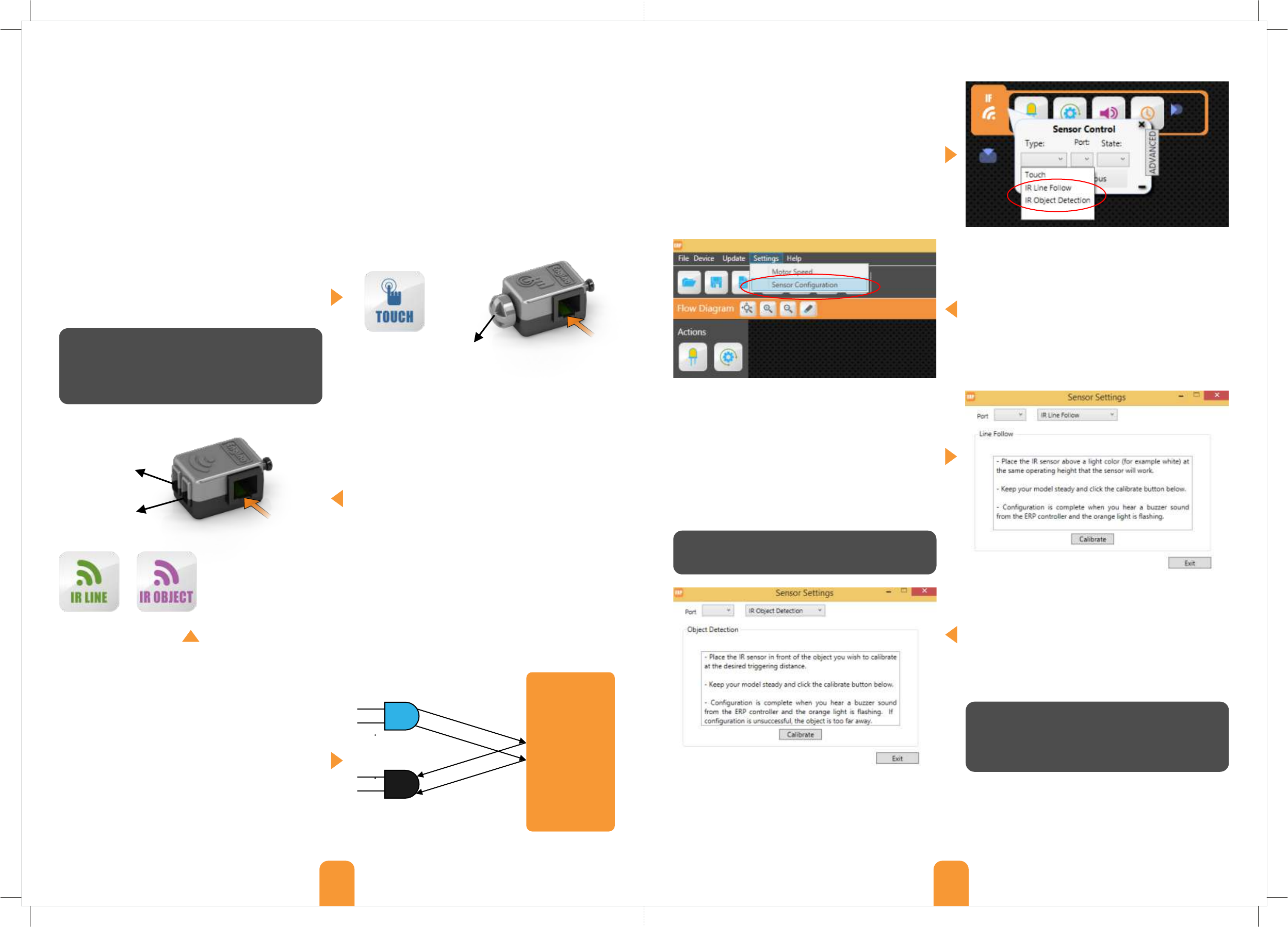
When you create a program that contains an infrared
sensor you will need to configure its state so that the
robot will “know” when to act in a TRUE or FALSE
situation. This can only be done within the ERP
software. Place a conditional statement (if, while etc.)
inside the flow diagram and make a right-click to view
its properties. Click on the drop-down menu of the
“Type” variable and choose between two types of IR
configurations: Line Follow and Object Detection,
depending on what you want your robot to do.
Remember to place the correct sensor icon in the port
of the ERP Simulator according to your robot’s set up
(either 2 or 4 for the Infrared sensors) and choose the
corresponding port in the statement menu.
The configuration is done from a special window. To
view this, go to the main menu and under “Settings”
tab choose “Sensor Configuration”. Inside the pop-up
window choose the configuration you wish to make in
the same type as in the conditional statement block.
From the object detection configuration window
choose the correct port and follow the instructions.
“Place the IR sensor in front of the object you wish to
calibrate at the desired triggering distance. Keep your
model steady and click the calibrate button below.
Configuration is complete when you hear a buzzer sound
from the ERP controller and the orange light is flashing. If
configuration is unsuccessful, the object is too far away”.
Important: You can only have one configuration mode each time, either line follow or object detection and
the triggering point for TRUE or FALSE will be the same for both IR sensors. Also, for more accuracy, note the
following factors: 1) light; configure the sensors within the environment where the robot will be used e.g. in a room
with the same light. 2) reflection and transparency; an object that reflects light (e.g. a mirror) works as if it was white
colour, while a transparent object works as if there was no object at all.
Connect RJ
cable here
ERP Simulator icon
for touch sensor
ERP Simulator icons
for IR Line Follow and
for IR Object Detection
When the switch is pressed the circuit closes, there
is a current flow and the sensor is TRUE.
When the switch is not pressed the sensor is FALSE
because no current is flowing through its circuit.
From the line follow configuration window choose
the correct port and follow the instructions. Note that
this procedure works only with light colours, so do not
use black colour for configuration. “Place the IR sensor
above a light colour (for example white) at the same
operating height that the sensor will work. Keep your
model steady and click the calibrate button below.
Configuration is complete when you hear a buzzer sound
from the ERP controller and the orange light is flashing”.
State TRUE activates the IR sensor for white colour.
State FALSE activates the IR sensor for black colour.
State TRUE activates the IR sensor for distances
equal or smaller than the triggering distance.
State FALSE activates the IR sensor for distances
larger than the triggering distance.
OR logic gate: When
one or both inputs are
“True” then the output
is “True”. Only when
both inputs are “False”
the output is “False”.
For example, the
motor will rotate while
sensor 2 or sensor 4 or
both are activated. If
none of the sensors (2
and 4) is activated the
motor will not rotate.
AND logic gate: When
both inputs are “True”
then the output is
“True”. Otherwise, the
output is “False”. For
example, the light will
work only if both
sensors 1 and 3 are
activated at the same
time. When one of the
two or none of them is
activated, the light will
not work.
Logic gates
A logic gate is the application of Boolean algebra in electronics. The Boolean algebra has two values: 1 for True and
0 for False. For the ERP, two logic gates are used: OR and AND. Their results help the robot decide whether it will
execute the conditional statement or not. To use them, right-click on any conditional statement block and find the
logic gates at the bottom of the “sensor control” menu. Click (at the right-down corner) to cancel the logic gates.
While conditional statement: the WHILE
block is activated as long as the condition
of the sensor is met (True or False), thus
playing the subprogram in a loop. Once the
condition stops, then the loop will stop too and the
rest of the program will continue accordingly. For
example, while the touch sensor is pressed, the buzzer
and LED light will be on (until the sensor is released).
IF/ELSE conditional statement: the
IF/ELSE block has two parts. The sequence
in the first part is activated when the
condition of the sensor is met (for example
True), the same way as the IF block. When the
condition is opposite (for example False) then the
robot will execute the ELSE sequence, that is the
blocks placed inside the second part of the block.
The decision making capability of the robot is based
on sensors’ feedback. The statements of the sensors
are called conditional because they are executed only
when the condition of the sensor is met. There are
four conditional statement blocks: IF, While, IF/Else
and Repeat until. Right-click on the blocks to change
their properties: type of sensor, port, state, after/with
previous, advanced menu and logic gates. If the
commands are in conflict (e.g. controlling the same
port) then by default the new command will apply.
IF conditional statement: the IF block is
activated when the condition of the sensor
is met (True or False). For example if the IR
sensor detects black colour then the motor
will rotate clockwise. Note that if the sensor
is activated for a second time, the loop will start again
even if the previous sequence is not finished.
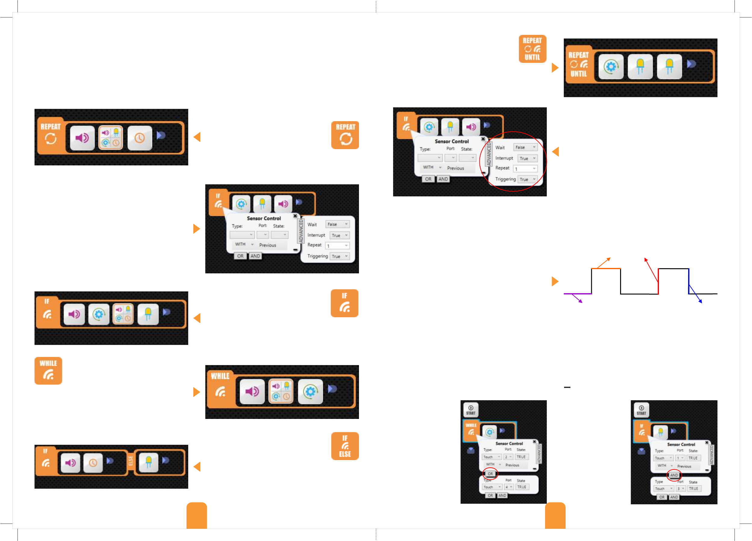
Repeat until conditional statement: the
REPEAT UNTIL block is used for repeating a
specific sequence of commands that will
stop only when the sensor is activated. In
other words, the program gets into a loop
when it reaches the block and gets out of it when the
condition of the sensor is met. For example motor
rotates continuously until the touch sensor is pushed.
Conditional statements
Repeat statement
The “Repeat” block is used for repeating a
specific sequence of commands. Inside the
statement you can put any action or
function block in order to create a routine.
Then right-click to set the number of repeats.
Controls - Statement blocks
A statement is simply a set of instructions that tells a robot what to do. In the Engino software, statements are
formed by placing the appropriate blocks inside the flow diagram. There are five types of statement blocks: If,
While, Repeat, If/Else and Repeat until. These can be found on the left side of the screen and you can add them in
the flow diagram with double-click or drag and drop. Place elements or function blocks inside the statement blocks
in order to create a sequence of commands. Note that you cannot place other statements inside the statement
blocks directly. If you wish to add a statement within a statement you can use a function block.
Advanced menu
Repeat: with this variable you can set how many times
the conditional statement will be executed. To do this
change the number inside the box (by default is “1”).
Interrupt: control whether the statement will be
interrupted (true) or not (false) when called by another
statement. For example, a motor rotates when a
condition exists. If interrupt is “true” and another
statement calls the motor, even if first condition still
exists, it will go to the second one. By default is “True”.
Triggering: control how the sensor is activated
electronically. If triggering is “True” (default value) the
sensor is activated on the rising edge or on the falling
edge of the digital signal. This practically means that a
touch sensor would activate when it makes the
transition from not pushed to pushed (rising edge) or
from pushed to not pushed (falling edge), depending on
the state of the sensor (TRUE or FALSE respectively).
27 28
low level
high level
falling edge
rising edge
If triggering is “False” the sensor is activated on the high level or on the low level of the digital signal. This means
that a touch sensor would activate when is pushed (high level) or not pushed (low level), depending on the state of
the sensor (TRUE or FALSE respectively).
Wait: control whether you want the robot to wait until the conditional statement is executed and then continue
with the rest of the program. In other words, the remaining program (blocks outside the conditional statement) will
continue only when the sensor is activated. To set this choose “True” on the drop-down menu (by default is “False”).
FALSE
TRUE
Follow the instructions below in order to create your own “line following robot” using two infrared sensors:
ŸFind the instructions in pages 56-58 and build the Engino humanoid robot;
ŸDraw a black line 5 cm thick on a white piece of paper with a black marker (alternatively you can stick black tape)
and create a path with smooth turns. You can also download a path at enginorobotics website (see below);
ŸOpen the ERP software on your computer and connect your robot with USB cable (click the USB button);
ŸPlace the appropriate icons on the ERP simulator according to the humanoid (e.g. IR LINE in ports 2 and 4);
ŸCreate the program you see below and right-click in every block to adjust the variables;
ŸConfigure the IR sensors in ports 2 and 4 so that they activate when they detect black colour (State FALSE). For
this go to the main menu and choose “Settings/Sensor Configuration” and follow the instructions.
ŸSend the program to the ERP device (click on the send button);
ŸPlace the humanoid on the black line with sensors looking downwards. Put motor switches in position II. Then
push play to test the program. The humanoid should follow the black line and stop at white colour.
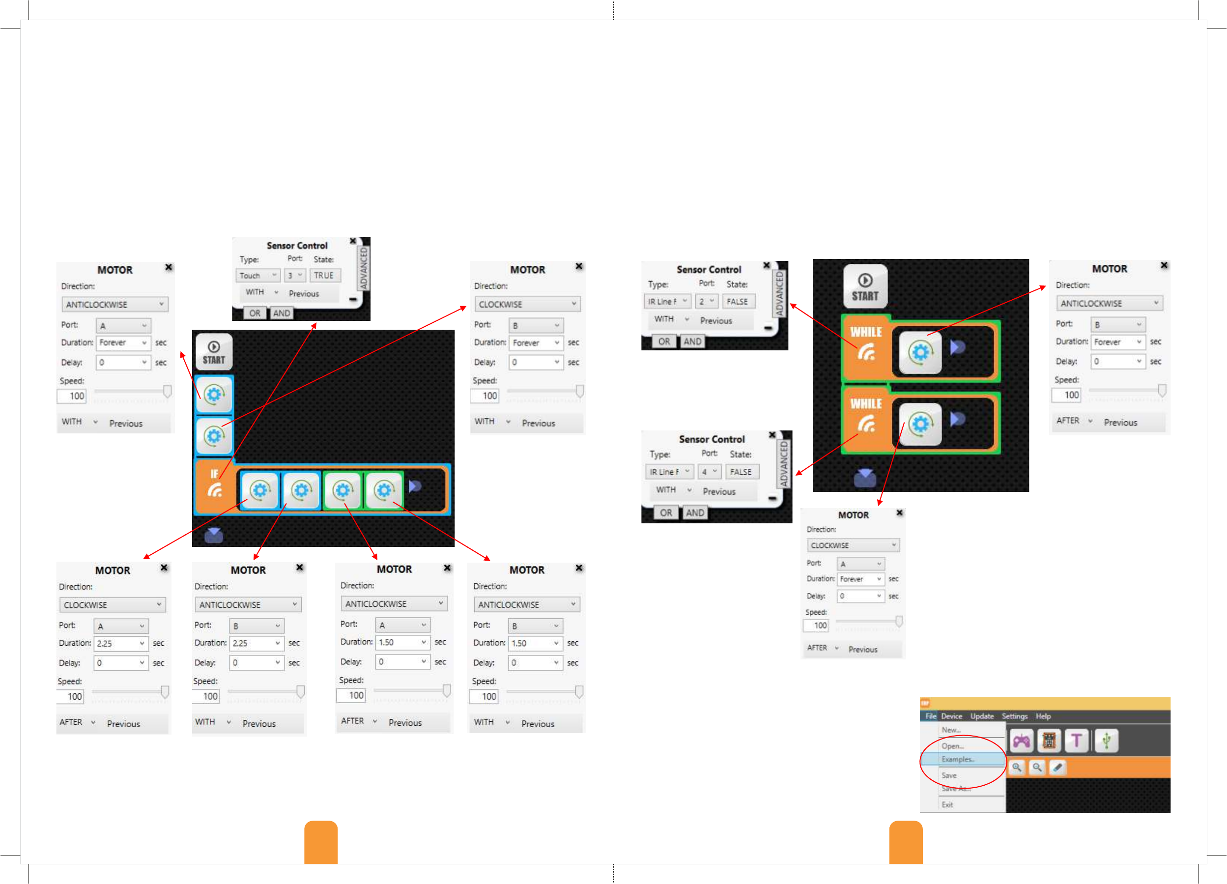
Follow the instructions below in order to create your own “obstacle avoiding robot” using a touch sensor:
ŸFind the instructions in pages 53-55 and build the Engino jeep car robot.
ŸMake sure you connect all cables correctly. The touch sensor must be connected in port 3 of the ERP controller.
ŸOpen the ERP software on your PC, turn on and connect your robot with USB cable and click the USB button.
ŸPlace the appropriate icons on the ERP simulator according to the model (e.g. motor in port A, TOUCH in port 3).
ŸCreate the program you see below and right-click in every block to adjust the variables.
ŸSend the program to the ERP device (click on the send button).
ŸPlace the jeep car on the floor. Put motor switches in position II. Then push play to test the program. The car
should move forward until it finds an obstacle (for example a wall) and the touch sensor is activated. When this
happens it should move backwards and turn 90 degrees to the right in order to avoid the obstacle.
ŸYou can adjust the times for more accurate motion and also add buzzer and LED lights if you wish.
Example program 2: line following robot
Example program 1: obstacle avoiding robot
Type: IR Line Follow
Port: 2
State: FALSE
WITH Previous
Type: Touch
Port: 3
State: TRUE
WITH Previous
Type: IR Line Follow
Port: 4
State: FALSE
WITH Previous
Direction: ANTICLOCKWISE
Port: B
Duration: Forever sec
Delay: 0 sec
Speed: 100
AFTER Previous
Direction: ANTICLOCKWISE
Port: A
Duration: Forever sec
Delay: 0 sec
Speed: 100
WITH Previous
Direction: CLOCKWISE
Port: A
Duration: 2.25 sec
Delay: 0 sec
Speed: 100
AFTER Previous
Direction: ANTICLOCKWISE
Port: B
Duration: 2.25 sec
Delay: 0 sec
Speed: 100
WITH Previous
Direction: ANTICLOCKWISE
Port: A
Duration: 1.50 sec
Delay: 0 sec
Speed: 100
AFTER Previous
Direction: ANTICLOCKWISE
Port: B
Duration: 1.50 sec
Delay: 0 sec
Speed: 100
WITH Previous
Direction: CLOCKWISE
Port: A
Duration: Forever sec
Delay: 0 sec
Speed: 100
AFTER Previous
You can find examples, printable templates and the
solutions to the experimental activities at the website:
www.enginorobotics.com/teaching_resources/examples
You will need to complete a simple form to gain
access. In order to view an example program simply go
to the menu on the top left corner, click “File” and then
“Examples...”. Choose the example you want according
to the Engino robotic model you have built. The
program will appear inside the flow diagram.
Direction: CLOCKWISE
Port: B
Duration: Forever sec
Delay: 0 sec
Speed: 100
WITH Previous
More examples, templates and solutions
29 30
03 04
Theory
“At bottom, robotics is about us. It is the discipline of
emulating our lives, of wondering how we work”. This
quote from the professor of Computer Science Rod
Grupen best describes how scientists perceive
robotics: a simulation of real life functions using
mechanics and computers. But will humanity ever be
able to create robots that have feelings and can truly
take their own decisions in situations that are not
predicted in a programming language? Whatever the
future holds, young people of today must have a clear
view of what robots are, starting from the basics of
robotics and programming sciences and ending up
building their own fully functional devices! The next
pages are specially designed with this idea in mind!
What we will learn
History of Robotics
The history of robotics has its origins in the ancient
world. Since antiquity, people were thinking about
artificial constructions that could replace humans by
doing different tasks, as having minds of their own. A
Greek myth tells the story of Talos, a gigantic bronze
humanoid that was built by Hephaestus (the Greek
God of blacksmiths), for protecting the island of Crete.
Accounts of robot-like creatures are found all over the
world from Norway to Middle East, India and China, in
various forms: texts, drawings, paintings and even in
ancient Egyptian hieroglyphics.
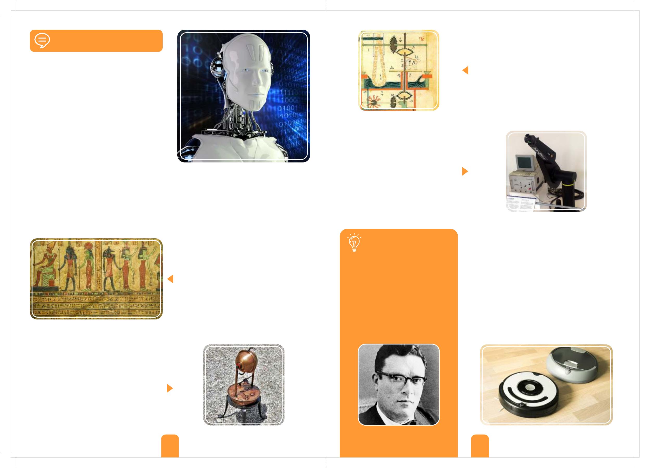
Ancient inventors and craftsmen set out to build the
early “robots”. These ranged from simple to complex
devices designed to perform various tasks in
seemingly autonomous ways. Hence, they are called
automatons, translated from Greek as “acting on one's
own will”, even though technically this was not actually
the case. As early as the 4th century BC, Archytas had
supposedly created a steam flying device called
“pigeon”. People of his time said that his machine
could fly a distance of 200 meters! Heron of Alexandria
(10 - 70 AD) was also an inventor who had many
creative ideas such as the automatic opening of
temple doors, wine purring statues and steam or wind
powered machines such as his famous “aeolipile”.
Al-Jazari’s drawing of a hydropowered chain pump
In the 1960's, engineers were tackling the problem of robotic
movement by creating robotic arms and legs inspired by
nature. During 1970's and 1980's, advanced technology and
small in size computer parts made it possible to put all the
components on the robot itself rather than having them
attached with wires on an external computer. Since the
1990s, robots became even more advanced, utilising
multiple complex tasks. Nowadays they are used in every
aspect of the human life, from home entertainment and
assistance (like AIBO the robotic dog, 1999 and Roomba the
robotic vacuum cleaner, 2008) to industrial applications (like
building cars) and explorations (like Epson the flying robot,
2004) even in outer space (like the Mars exploratory robots,
2004). The exciting part is that this is just the beginning as
the future of robotics looks very promising!
In the middle ages, we can find many examples of
automatons, usually in the form of animals or humans.
People built fun machines that were programmed to do
simple tasks like moving their feet or turning their heads,
using precise clockwork technology. The Muslim engineer Al-
Jazari (1136–1206) described 100 automated, mechanical
devices in his book: “The Book of Knowledge of Ingenious
Mechanical Devices”. Later on, the french inventor and artist
Jacques Vaucanson (1709 - 1782) played an important role in
robotics' development as he tried to demonstrate how
things work in nature. Some of his inventions included
figures that play real instruments (flute and tambourine) and
the famous “digesting duck”, which imitated food digestion.
In 1898, the Serbian-American inventor Nikola
Tesla demonstrated the first radio-controlled
vessel. Real robots, meaning those that are able
to receive feedback from their surroundings and
react to it, only appeared in the 20th century. In
1948, Grey Walters created small robotic turtles
with light and touch sensors that could search
for “food”. Some years later, George Devol
patented his Unimate robot that was capable of
doing industrial work. This was installed in 1961
in a factory to lift hot pieces of metal from a die
casting machine and stack them up.
This booklet of Discovering STEM: Robotics contains a comprehensive theoretical section with building
challenges and interesting facts, so that you can learn all about robots and their applications in daily life. The
®
booklet also contains an Engino Robotics Platform (ERP) manual, explaining in detail all aspects of Engino’s
innovative robotic system. Discover all the scientific principles applied through experimentation, step-by-step
guides and fascinating exercises. Follow the building instructions to build exciting robotic models such as an
experimental robot, a dinobot, a forklift, a jeep car, a humanoid, a grabber, a house and a pedestrian
crossing. A lot more learning material is available online! A Unimate robotic arm
Robotics cannot exist without computer programming
Isaac Asimov (1920 - 1992)
Automatic devices were found in hieroglyphics
Two types of Roomba vacuum cleaners
Modern replica of Heron’s aeolipile device
Did you know?
The science fiction writer Isaac Asimov
devised the “Three law of robotics” in his
short story “Runabout” published in 1942.
These are: 1) a robot may not injure a
human being or, through inaction, allow a
human being to come to harm; 2) a robot
must obey the orders given it by human
beings, except where such orders would
conflict with the First Law; 3) a robot must
protect its own existence as long as such
protection does not conflict with the First
or Second Law.
05 06
Definition of Robot
Types of Robots
The term “robot” was first introduced in 1920 by the
Czech writer Karel Capek in his novel R.U.R., meaning
“labour” in Slavic language. This shows how people
first conceived the notion of robots: “devices
performing tasks that are too dangerous, complicated
or just boring for humans to do”. However, a more
scientific definition is that a robot is a mechanical
device that receives feedback from its surroundings
and is able to respond to it accordingly. Therefore,
robots have, to a certain degree, real autonomous
behaviour and in a way they think and act for
themselves. However, this depends on their program
language and their pre-determined commands.
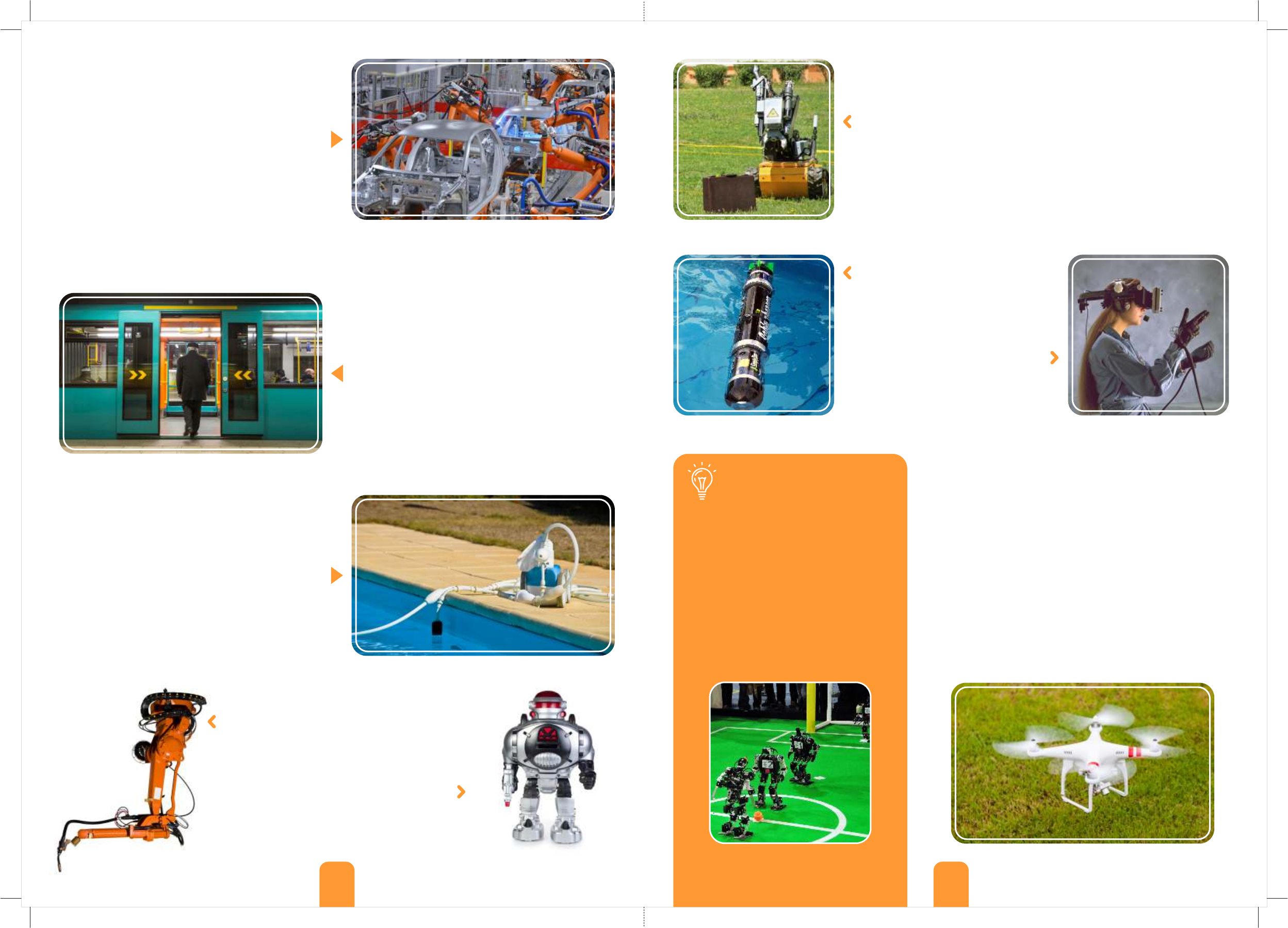
Medical robots, used in health sector (hospitals, pharmacies, clinics and
medical centres) for training doctors or even performing accurate procedures
e.g. surgery robot.
Military robots, which are part of advanced armies and police forces. They
are used instead of people, usually in life threatening situations, for
transporting ammunition, bomb disposals or even engaging in war fights,
e.g. small tank robots.
Domestic and service robots, which are robots designed for commercial
everyday use at home or at work, making life somewhat easier e.g. vacuum
cleaner robot.
Exploration robots, which are robots
used for exploring harsh environments
that are too difficult for people to reach
like Earth’s caves, oceans (e.g. water
robots) or even other planets.
Virtual robots, which are robots used
in virtual conditions. These are usually
some type of large, eye-covering
glasses with screens assorted with
special gloves in order to see and feel
inside the world of augmented reality.
Hobby robots, which are robots created from robot-
enthusiasts rather than large production companies. Their
purpose can be experimental for testing different
components and technologies or simply recreational e.g.
flying drone.
Competition robots, which are robots made for competing
other robots in different challenges. This category is similar
to the previous one because hobbyists are those who usually
organise competitions in order to test their robots’ skills and
gain valuable experience. Competitions are also held among
robot development teams from around the world, helping
them to improve their designs.
For example, an automatic sliding door (found in
shops, hotels etc.) is robotic. It has a motion sensor
which sends a continuous infrared signal. If this signal
is interrupted, because someone gets in front of the
invisible beam, the central processor gives the
command for the door to open. After some seconds
the door closes and the procedure is repeated. Other
examples of robots include domestic heating systems
and motion-activated lights. However, remote
controlled cars or toys are not robots. They just receive
direct commands through a controller in order to
move. As this is not feedback, they are not able to
make decisions concerning the objects around them
e.g. stop before hitting the wall.
Robots come in a variety of forms and shapes and can
perform single or multiple tasks in different settings
and conditions. In this way one robot may belong to
more than one category. So, how can we distinguish
one from another? A handy categorisation can be
according to the functionality of each robot. This gives
us some information about the usefulness of the
robot and an idea of how it should look like or what
components should have in order to perform well. The
main types according to function are described below:
Industrial robotic arm Toy robot
Did you know?
There is a special football tournament for
robots called “RoboCup”! The first robots
that took part in a robotic football game
were created in Japan in 1997. The players
were able to locate the ball and shoot it
with their legs. The manufacturers of
these robots have set as their goal that
the robotic football team will compete
with the men’s 2050 World Cup winner
team and even win the match! Do you
think robotic technology can reach such
level of football skills until then?
Bomb disposal robot
Water robot
Industrial robots, which are automated robots
used in factories for lifting heavy objects or
making routine jobs e.g. welding, painting and
handling materials.
Entertainment robots, which are robots made
mostly for fun and have less practical use, e.g.
robotic toys.
Robot football players
Robotic metro doors with touch sensor
Robotic arms used in a car assembly line
Robotic pool cleaner
Flying drone robot
Virtual reality gear
07 08
Applications in real life
The 21st century is surely the age of robotic science and advanced technology! Robots can be found everywhere,
not only the ones with the humanoid look that people know best, but often in very simple forms like heat sensing
systems in houses and distance sensors in cars. The applications of robotic systems in daily life are vast and people
are becoming more and more dependable on them. Read below about some characteristic examples of robotic
®
usage and challenge yourself by building and programming the suggested models from Engino Robotics. You can
find the models’ building instructions in the last pages of this booklet.
People have always been amazed by the wonders of
outer space and the prospect of exploring new worlds
or even discovering alien life forms. However, the
conditions outside Earth's atmosphere can be
devastating to humans: solar storms, lack of oxygen,
gravity fields and absolute zero temperatures (−273
degrees Celsius) are among the dangers. All these
require very expensive space suits and years of
training and planning just for a short stroll around the
Earth or on the Moon. As for distance (e.g. a journey to
another planet) explorers must be willing to return to
Earth after decades of years or even not at all!
Fortunately, robots exist! They are ideal for space
exploration as they eliminate all the survival problems
and they don’t actually mind how much time they
spend in a mission. With their advanced capabilities,
they can explore a planet’s surface, analyse its soil and
atmosphere, seek for water and other chemical
substances and send back to Earth tons of valuable,
high resolution images. Currently, there are two active
Mars Exploration Rovers, Opportunity and Curiosity, as
well as various other robots which orbit around
asteroids, comets and planets, making them worthy
representatives of humanity!
Space exploration
Mars Rover “Opportunity”
®
Build the Engino
“Humanoid robot”
model (pages 56-58)
and put the IR
sensors face down to
follow a certain path
or face forward to
detect “dangerous”
objects and warn
with sound. You can
also control its
movement with the
EnginoRobot BT
application through
a smart device.
®
Build the Engino
“grabber robot”
(pages 59-63) and
program the touch
sensor to pick up
objects. Guide its
movement with the
help of IR sensing
technology.
®
Engino “automated
house” model
®
Engino “humanoid” model
Mars Rover “Curiosity”
®
Engino “grabber” model
®
Engino “pedestrian
crossing” model
Did you know?
On November 12th 2014, for the first time
in history, a robotic module named Philae
landed on the surface of a comet! This
impressive feat was part of the Rosetta
Space Mission, a robotic space probe that
was orbiting and studying the comet 67P
since January 2014. The mission seeks to
find if the comet can provide a key to
deciphering the origins of the solar system
and life on Earth.
Representation of the Rosseta Space Mission
Traffic lights: traffic control is a very important aspect of road safety, for both drivers and pedestrians. Robotic
systems make sure that each traffic light is on at the correct time and order. Especially, in pedestrian crossings
Building Challenge
(zebra type), people cross the street with the help of a
touch sensor. This is set to execute the following
sequence: from green light on, it changes to orange
light and then to red light for cars and in parallel, it
switches from red light on to green light for
pedestrians, while emitting a beeping sound. After
some time the reverse sequence is activated to bring
the lights back to their normal state.
Try out this fun exercise by building the Engino robotic
model of “pedestrian crossing” (pages 64-67) and help the
®
Engino man to walk across the road in a safe manner!
Use the printed cardboard for the road found in the set.
Robotic houses: modern houses are becoming
increasingly “smarter” and many manual functions are
now done automatically! For example, automatic
doors open and close using motion detectors, while
heat sensors detect variances in temperature and
activate the cooling or heating system. Engineers are
already experimenting with smart fridges that will be
able to re-stock on their own by detecting the absence
of specific products (milk, eggs, butter) and ordering
them online!
Experiment with house automation by building the
®
Engino “automated house” model (pages 68-70). Set the
door and fan into motion using IR or touch sensors.
Dangerous missions: robots can successfully
replace people when it comes to dealing with
dangerous tasks. This way human lives are not put in
risk and missions are completed faster and better
because of the advanced capabilities of robots. For
example, a robot can detect dangerous materials
which can be defused with the help of remote human
control. The operator uses the sensors of the robot to
see and manipulate the bomb.
Industrial use: another increasing use of robotics
is in the industrial sector, where robots replace the
work of people. These are usually stationary or line-
guided moving robots that have a flexible arm for
lifting heavy objects or doing delicate work (like
welding). They are ideal for factory assembly lines.
People worry that automated procedures result in less
jobs, but this is not true as new positions are created
for handling and fixing the robotic machines, not to
mention the better quality of products.
Building Challenge
Building Challenge Building Challenge
09 10
As we have seen so far, there are tons of different types of robots, used in a variety of applications. People,
basically, interact with robots on a daily basis without even noticing it! Although there is such an abundance of
robots, they have three common components: a mechanical form of structure, a controller which contains the
necessary hardware and a variety of peripherals for interacting with the environment. Of course, robots also
require some sort of power source that comes in the form of a battery carried by light weight robots or power
socket connection for stationary and heavy robots.
Robotic components
Controllers
Peripherals
Structure
Robots have a specific type of structure according to their
functionality. The parts are carefully selected as to provide
the chosen designed features e.g. stability, flexibility, nice
look, waterproofing etc. Usually engineers draw inspiration
from nature and their robotic inventions imitate aspects of
life itself. Some categorise robots according to how they look
and the means they use for moving. In this sense, we have
the following types of structures: 1) stationary robots that do
not change position e.g. arms in factories, 2) wheeled robots,
with any number of wheels attached or even tracks, 3)
legged robots that resemble people (humanoid) or animals
(e.g. dog), 4) animal-behaviour robots, capable of swimming,
flying and jumping, 5) swarm robots that have a simple
design and are able to communicate with each other in
order to do complex tasks (e.g. building a bridge).
The controller is the brain of the robot. It is the main
processing device that is connected with the sensors and all
other electronics comprising of its “logic and senses”. There
are two approaches on the development of robotic
controllers: a) imitation of biological systems and b)
Artificial Intelligence (A.I.). The first works at finding out
how the human brain works and how it causes certain
behaviours, applying this knowledge on robots. On the other
hand, A.I. approach studies the computer and tries to imitate
the behaviour itself using mechanical means.
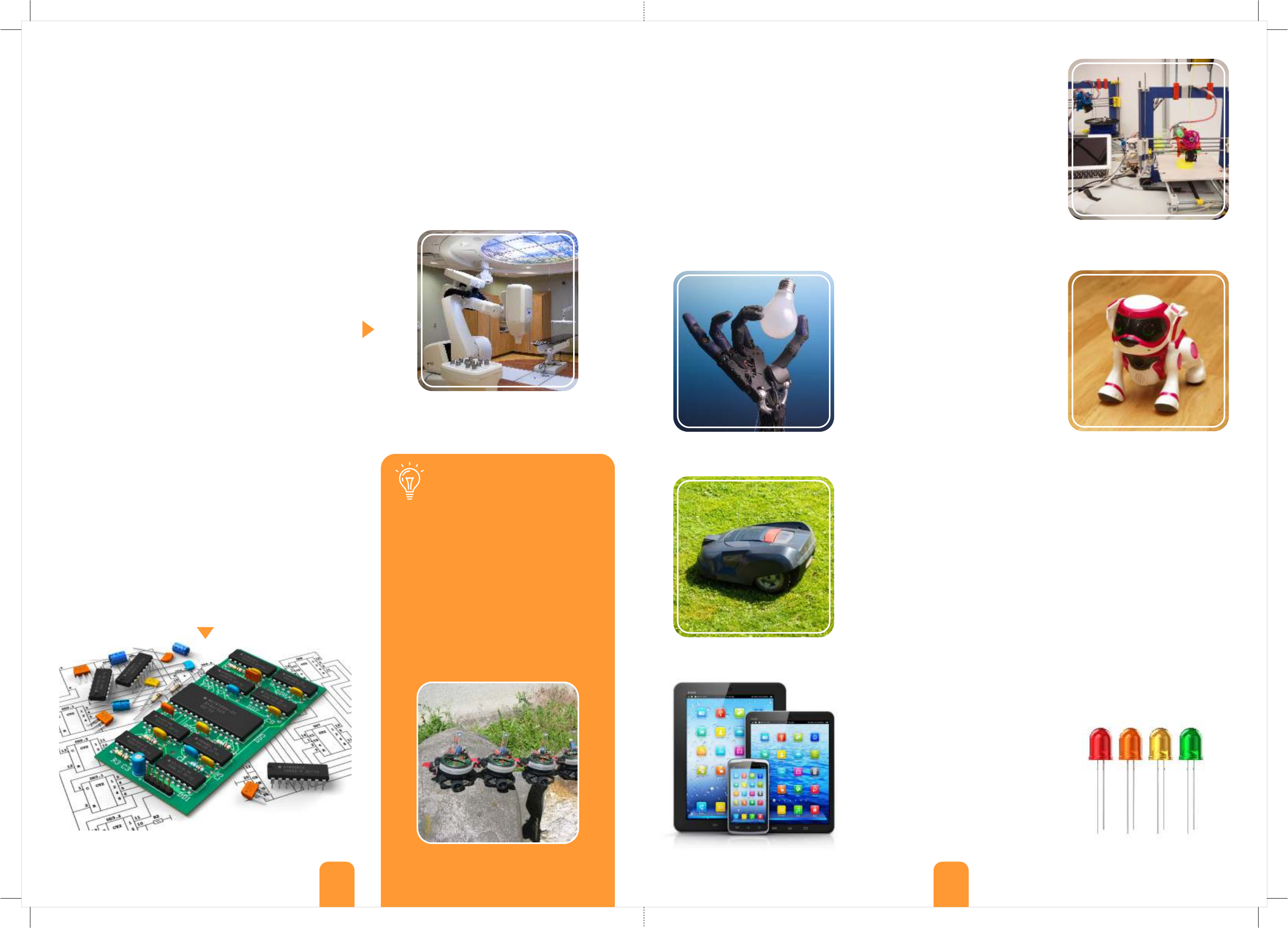
Peripherals are devices connected with the micro-controller through cables
(or sometimes wirelessly) to enhance the use of a robot. These are
essential to robots for utilising the tasks that were designed for and help
them to interact with their surroundings. Robots receive information
through different types of sensors. They then act accordingly using a
different set of peripherals for sending information back to their
environment through movement, sound, light etc. These are called
actuators and effectors as they act on and affect the environment.
Peripherals come in a variety of shapes, sizes, colours and functions,
depending on the purpose of the robot built. Below you can see the
different types of peripherals used for utilising main functions: touch and
vision sensors, motion, indicators and other peripherals.
Touch: called also tactile sensors,
they work by physical interaction
with the environment and they
are sensitive to touch, force and
pressure. Their most common
use is found on the touch screens
of smartphones and tablets
(capacitive and resistive sensors).
Vision: sensors that use wave
technology to measure the
changes in the electromagnetic
radiation spectrum. The way light
and other waves (infrared, sonar
etc.) bounce off different objects creates variations that can be detected
and measured by the sensors. The robotic vision technology has a vast
range of applications: from detecting and recognising objects (or living
creatures) to motion analysis and even scenery reconstruction (e.g. 3D
mapping of a building). An example of how accurate vision technology can
be is the driverless vehicle, which works entirely by sensor feedback
combined with GPS technology.
Motion: these are the most common output peripherals (actuators) that
convert electrical or other form of energy into motion. Usually electrical
motors are preferred for rotating wheels or gears with light load. More
advanced robots use hydraulic or pneumatic pressure for more strength
and precision (e.g. linear motion).
Indicators: robots are equipped with LED (Light-Emitting-Diode) lights and
digital screens for displaying different types of indications and warnings
such as flashing light, text, images or even animation.
Other: this category includes other
peripherals that send or receive
information. For example a
microphone records sound and a
speaker transmits sound back. A Wi-Fi
device communicates wirelessly with
computers or other robots for
completing tasks (e.g. swarm robots).
Did you know?
Swarm robots are tiny devices connected
simultaneously via infrared light. These
robots work together in order to form
various shapes or complete complex tasks
that cannot be done by single units e.g.
passing over a gap. They are built in big
numbers out of simple materials, have low
manufacturing cost and are programmed
with simple commands. They are designed
mostly to provide answers related to
physical laws of natural swarms (birds and
insects) or to study teamwork dynamics.
Electronic components of a controller
A robotic hand imitating grip
A wheeled robotic lawn mower
A variety of peripherals make
a robotic 3D printer
Vision sensors on a robotic dog
A stationary robot used in medicine
Swarm robots collaborating together Different colours of LED lights
Smart devices connect through Wi-Fi
11 12
Programming
Statements
Did you know?
Most robots are much slower at doing
tasks than humans! This is due to the fact
that robots require a fair amount of time
in order to make a simple decision, as they
use algorithms to navigate through
decision trees. Even with the help of the
most advanced sensors this problem will
still exist, unless scientists make radical
changes in the algorithm design. That is to
find a way for the robot controller to
discard unnecessary data and maybe find
a revolutionary way for taking decisions.
Statements are written in lines of text ASIMO’s walking is slow because of algorithms
Besides the mechanical components, programming is
essential for the actual function of the robot. As
mentioned before, a device is considered robotic only
if it is capable of interacting with its environment. The
robot interprets all the receiving information and
decides on the appropriate actions according to its
program, through the micro-controller. Robot
manufactures usually provide their own programming
languages, resulting in many types of robotic software.
Fortunately, there are few basic notions that one
should follow when developing a program, which are
described next.
In computer programming, a statement is an instruction (command) that
basically tells a computer what to do. As you can imagine, these commands
should be precise for the robot to function well. Moreover, the sequence of
the commands, in other words “the task order”, is equally important.
Imagine that you follow instructions for baking a cake. If the recipe steps are
incorrect or they are written in the wrong order, chances are that you would
end up with a kitchen mess! In text-based programming languages, the
commands are usually written line by line and contain special characters for
®
different tasks. This is simulated in the Engino software, which contains a
TextEditor window that uses pseudo-language (not actual programming
language) allowing users to edit the different commands and view them
according to their sequence order as lines of text.
Conditional statements
By definition, robots are capable of making decisions depending on the surrounding conditions and their built-in
program. The sensors provide the robot with a continuous flow of information from its environment. Once a
specific value is reached and a predefined condition is true e.g. an InfraRed sensor detects black colour, then a
sequence of commands within the program instructs the robot what to do e.g. LED light on. These instructions are
called conditional statements, because the statements are executed only if a specific condition is met. The
conditions are based on a True or False (yes or no) decision that usually derives from Boolean logic and Boolean
algebra, meaning that the robot will execute a sequence or not according to these calculations. The Boolean logic is
explained in the next page about how to calculate the true results with two examples of logic gates (AND and OR).
There are slight variations among programming languages
about the type and number of conditional statements, as
they are used for different purposes. For robotics, there are
many types of conditional statements which cover the types
of decisions that a robot would make. Two of them are
described briefly below.
If...Then...Else conditional statement: the idea underneath
is that if a condition is true then the robot should execute a
specific sequence; Else it should execute a different
sequence. For example, if Infra-Red sensor detects black
colour, motor rotate clockwise; Else rotate anti-clockwise.
While conditional statement: while a condition is true the
robot should execute a specific sequence, therefore the
sequence will play in a loop (non-stop). When the condition
stops, the sequence will stop as well. For example, when the
touch sensor is pressed, LED light is switched on. When the
touch sensor is released the LED light will switch off.
Anyone who wishes to develop a computer program
should choose the programming language very
carefully, as they are designed and used for different
reasons. The most common high-level languages are:
ŸC++ language is probably the most widely used as
many applications are developed with it.
ŸJava can be used in any device where Java Virtual
Machine (JVM) is installed, regardless of the system.
ŸJavascript is a client web language used for making
operations on the PCs of the users instead of the
network server.
ŸPython is considered one of the easiest
programming languages to learn.
The most important element of any computer or robotic development is its programming language. Generally, a
programming language is a set of grammatical rules and vocabulary for instructing a robot to perform specific
tasks. A language consists of two main components: the form (syntax) and the meaning (semantics) of the text.
There are two general types of programming languages: low-level, that use the machine way of understanding
(machine code with numbers and symbols) and high-level that contain human language (in text form) and
automation, making the programming process more simple and understandable to people. In computer software,
the executable description of a program (created with a programming language) is called “source code”. Within the
source code there are algorithms, which are specific step-by-step sets of operations that need to be performed,
created by single programming elements called statements (explained below).
Programming languages
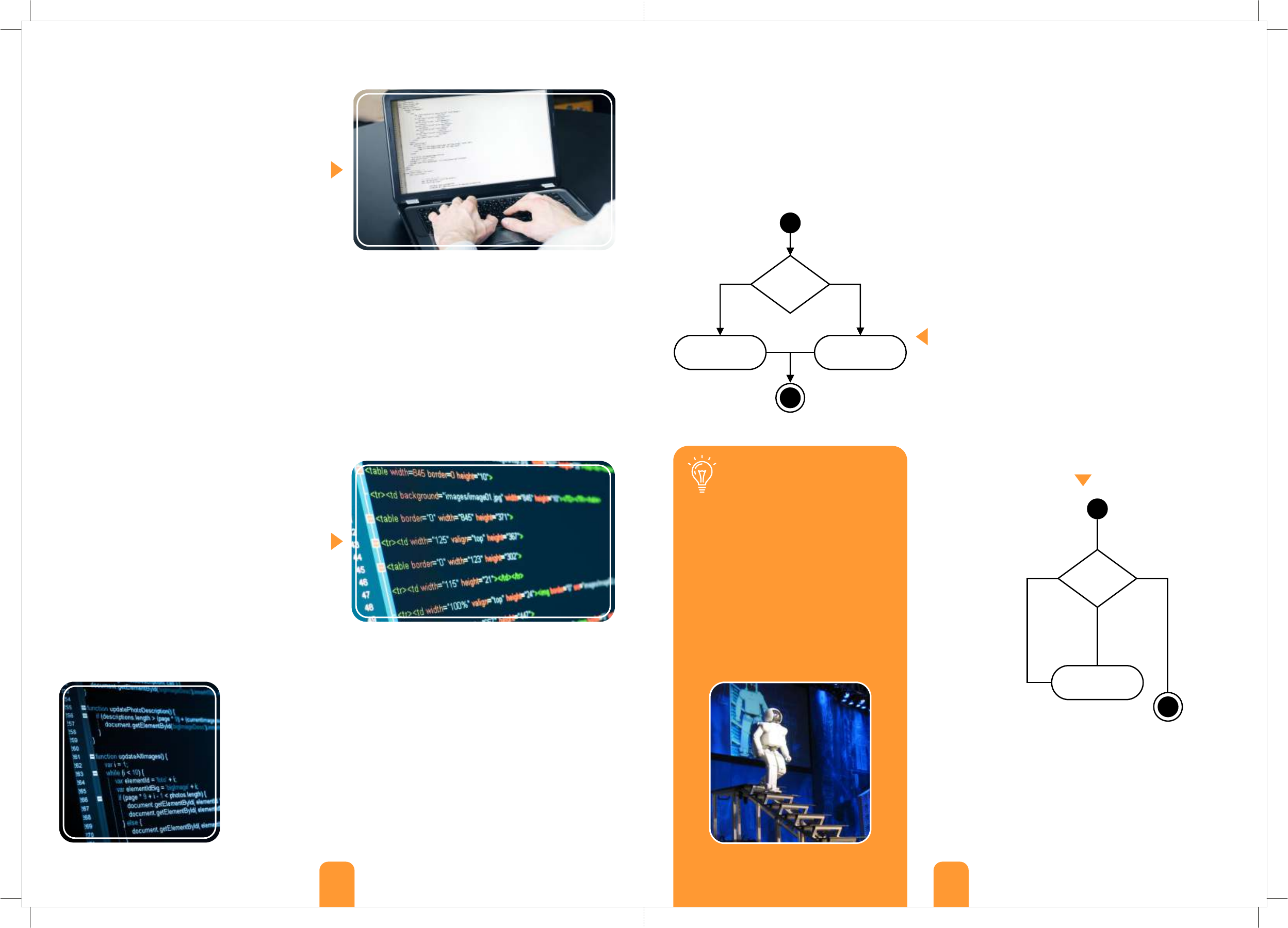
HTML language is used specifically for developing websites
A programmer at work TRUE FALSE
A
B C
IF (A=TRUE)
Then B
Else C
End IF
TRUE
FALSE
A
B
While (A=TRUE)
Do B
End While
“While” conditional statement diagram
“If...then...Else” conditional statement diagram
®
On the Engino Robotics software, you can add conditional
statements by using the IF, WHILE, REPEAT UNTIL and
IF/ELSE blocks. Furthermore, any sequence of statements
can be repeated either by using the “REPEAT” block, the
“repeat” variable, loop the whole program with the “start”
block or by using a “function” block.
13 14
Logic gates Manual programming
A logic gate is the application of Boolean algebra in
electronics. The Boolean algebra has two values: 1 for
True and 0 for False and uses three operations: AND,
OR and NOT. Most logic gates have two inputs that
result into one output. The combination of all this
data can be expressed through seven basic logic gates
named AND, OR, XOR, NOT, NAND, NOR and XNOR.
Their results help the robot decide which statement to
follow. Here you can see examples of AND and OR.
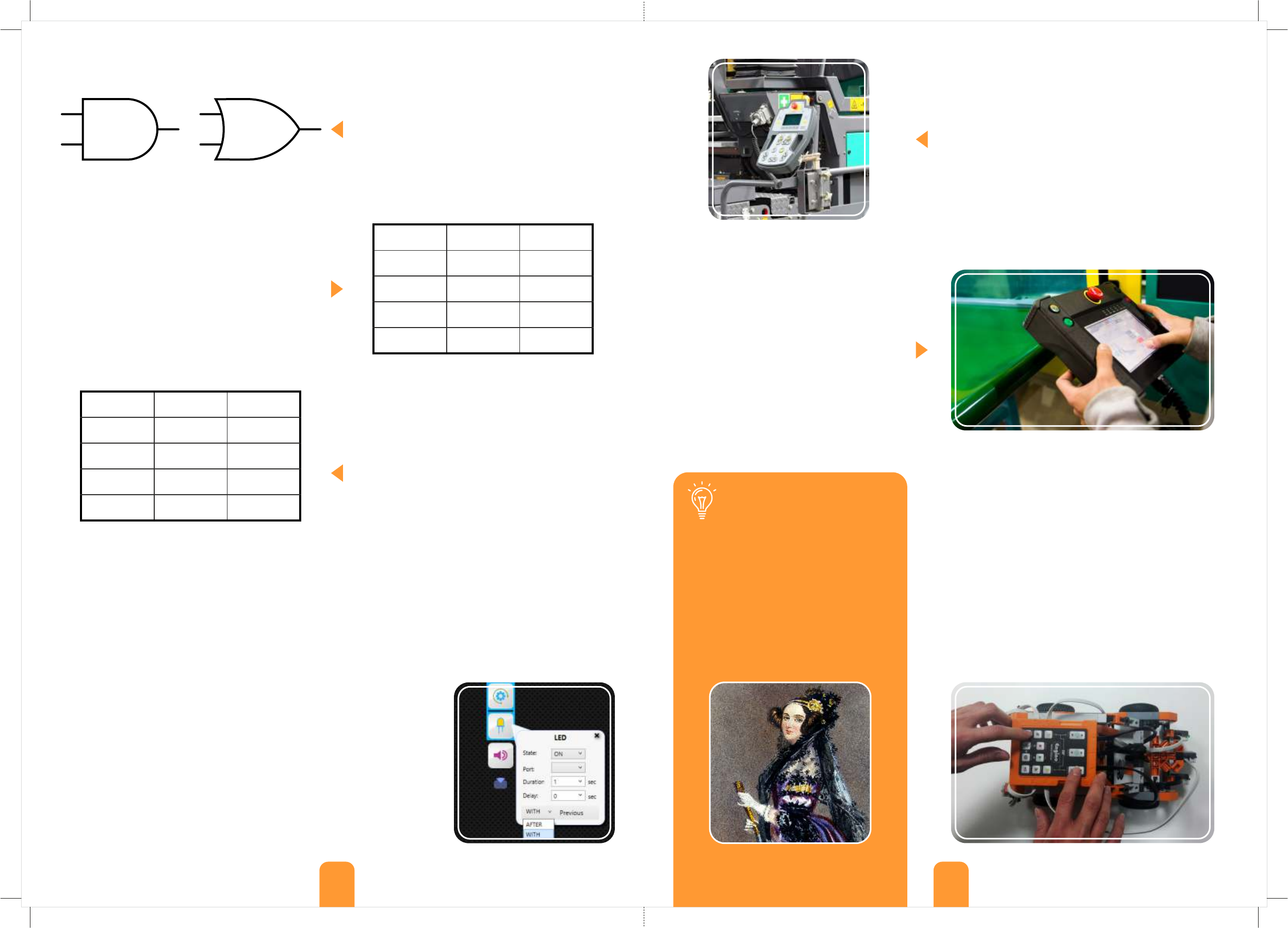
Logic gate AND: When both inputs are “true” then the
output is “true”. Otherwise, the output is “false”. This is
seen more clearly on the next table, where there is
only one combination of inputs in order to have an
output that is “true” (1), while the other combinations
result into “false” (0). In more practical terms, you can
use the AND gate for example if you want both
sensors to detect black (“true”) in order for the robot
to turn. If none (“false”) or only one of the sensors
detects black colour then the robot will not turn.
Logic gate OR: When one or both inputs are “true”
then the output is “true”. Only when both inputs are
“false” the output is “false”. As you can see in the next
table through the OR logic gate, there are three
combinations of inputs that create a result that is
“true” (1) and only one combination which results into
“false” (0). In comparison with the previous example,
you can use the OR gate if you want any or both of the
sensors to detect black in order for the robot to turn. If
none of the sensors detects black colour then the
robot will not turn.
Usually the procedure to create a factory robotic program is
by writing all the commands in a programming language,
checking if it works for certain conditions and adjusting it
back and forth until a satisfying result is reached. This
process requires complex coding skills and is often limited in
a specific range of motion e.g. a robot simply moves objects
from one place to another. But what if we want to mimic the
delicate movements of a worker to program a robot to do
actual human job without the need of writing complex
program instructions? Modern robotic technology allows us
to do just that through manual programming.
By using a teach pendant, which resembles a
traditional controller, the user controls the
robot remotely, so that it executes specific
movements e.g. pick up a car part and place it
on a conveyor belt. While the manual
programming is taking place, the sequence of
commands is generated and saved
automatically, thus the robot is ready to work in
the exact same way on itself. The programmers
are able to further edit the code, making any
changes related to speed, accuracy and
fluidness of the motion. When all is set, the
finished program is sent back to the robot.
Manual programming is one of the main features of the
®
Engino Robotics Platform. It is a very useful way to create a
program in real conditions without any knowledge of the
software itself. The user can simply press the buttons on the
ERP controller and record the sequence of commands that
the robot will execute in real-time. Once the program is
saved, it can be played manually at any time, even in loop.
Moreover, if the user wishes to refine the variables of the
commands and add conditional statements, this is done very
easily by connecting the device on a PC and sending the
program to the ERP software. When the adjustments are
completed, the program can be sent back to the robot for
testing.
Truth table for AND logic gate
Truth table for OR logic gate
Input 1
Input 2
Output
0
0
0
0
1
0
1
0
0
1
1
1
Input 1
Input 2
Output
0
0
0
0
1
1
1
0
1
1
1
1
A worker using a teach pendant
Machine that uses manual programming
Manual programming done with ERP
Parallel programming
After/With Previous variable
Very often robots have to do tasks simultaneously, for example turn their wheels, move their arms and light up LED
lights all at the same time. Therefore, simply by placing commands one after the other is not enough to fulfil the
required tasks. Programmers use special characters in order to create a program that contains parallel commands.
However, this is not an easy task, as robotic programming languages are complex and require advanced skills in
order to achieve parallelism, often with many repeated text lines.
®
One of the great advantages of the Engino Robotics Platform software is
that it allows parallel programming to be done very easily! The software
uses visual programming (blocks instead of text), which contains an
innovative After/With Previous variable allowing parallel features to run.
The user can choose between “after previous” if he/she wants the
command to be executed when the previous command is finished or “with
previous” if he/she wants the command to be executed at the same time.
The blocks that work in parallel are joined together with a coloured line.
This reduces the complexity of programming in a great extent, as the order
of commands become more clear and easy to formulate. With the addition
of delay and duration variables, each command can start and finish in any
desired order and time.
AND symbol OR symbol
Did you know?
The first computer programmer was a
female English Mathematician, named
Augusta Ada King (Countess of Lovelace).
Ada wrote the first algorithm in history
that was intended to be executed by a
machine in 1837. Specifically, it was an
algorithm to compute Bernoulli numbers
using the Analytical Engine, a proposed
idea from Charles Babbage for a
mechanical general-purpose computer.
Painting of Augusta Ada King (1815 - 1852)
®
The Engino Robotics Platform (ERP) is specially designed for Primary and Secondary school children and even
robotic hobbyists! It takes into account the latest technological trends and the most modern pedagogical principles
of learning. The set consists of all the necessary parts for studying robotics! These include an ERP controller, RJ
cables, one touch sensor, two InfraRed sensors, three motors, five LED lights and a USB cable! You can find easy-to-
follow instructions for all the robots in the booklet included. The booklet provides detailed explanations of the
different scientific principles applied and incorporates innovative activities for hands-on learning, along with a
detailed user manual with programming examples to get you started!
DISCOVERING
Science Technology Engineering Mathematics
pages of
theory and amazing facts!
12
pages of
user manual!
16
pages of
experimental activities!
8
pages of
step by step instructions!
32
www.engino.com
© Copyright Engino.net Ltd. All Rights Reserved.
HEAD OFFICE & FACTORY:
ENGINO.NET LTD
P.O.BOX 72100
4200, LIMASSOL, CYPRUS
Tel: +357 25821960
Fax: +357 25821961
Email: info@engino.com
Web: www.engino.com
UK OFFICE:
ENGINO TOY SYSTEMS LIMITED
4 CAPRICORN CENTER, CRANES FARM ROAD
BASILDON, ESSEX
UNITED KINGDOM, SS14 3JJ
Customer Service Line: 0333 200 0114
Email: info@enginotoys.co.uk
Web: www.enginotoys.co.uk
8-16+
TM
Product Code: STEM70
DEVELOPED FOR TEACHING ROBOTICS PROGRAMMING
ERP 1.2
PRO
AT PRIMARY AND SECONDARY EDUCATION
5 2 9 1 6 6 4 0 0 1 6 2 4
3D interactive instructions
to download on your smart device
models to build
8
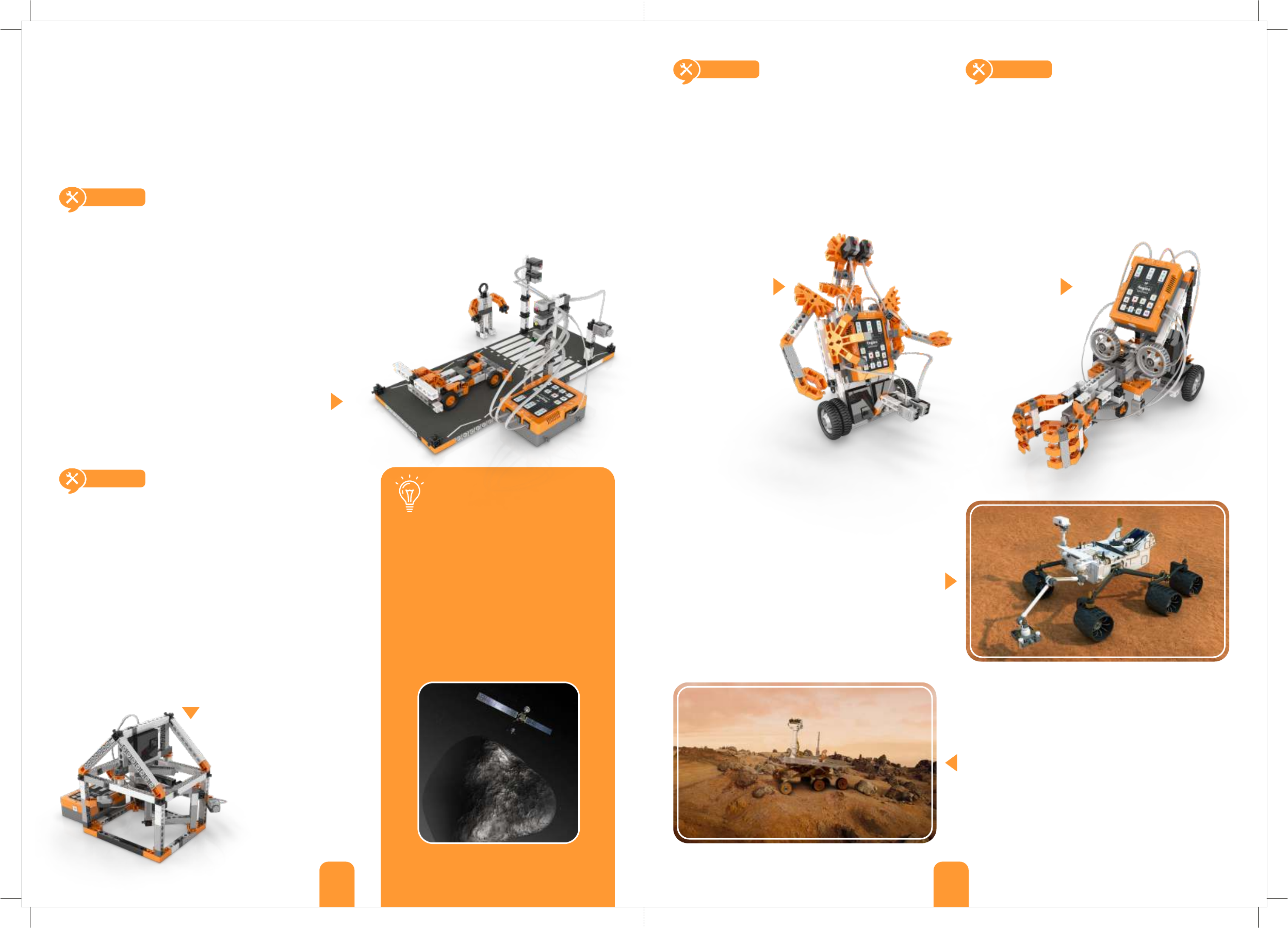
This unique grabber model simulates real life
factory robots that are programmed to follow
specific paths and do several tasks like carrying
heavy objects. Try this yourself and learn all
about loops and how to combine two different
types of sensors.
build a grabber robot
This exciting forklift model will help you
discover the different ways of controlling your
®
Engino robots. Learn how to use the GamePad
to move the vehicle or even program the forklift
wirelessly to lift, carry and set down objects.
build a forklift robot
What loops are.
How to use a REPEAT-UNTIL statement.
How to control a robot wirelessly.
Other types of digital and manual controls.
This experimental model will introduce you to
the main programming notions and the
®
innovative Engino Robotic Platform (ERP)
controller. It can also help you test different
variables and programs that you create either
manually or through the software.
build an experimental robot
What inputs and outputs are.
How you can manually program a robot.
Build this amazing humanoid robot and make use
of its dual capability! With the use of
programmable sensors the robot can distinguish
between black and white colours or detect
objects in its path. Learn how to use and calibrate
the infrared sensor so that the robot can follow a
line or warn you about obstacles.
build a humanoid robot
How infrared sensors work.
What logic gates and WHILE statements are.
Contents
Theory
03 What we will learn
03 History of Robotics
05 Definition of Robot
07 Applications in real life
09 Robotic components
11 Programming
ERP Manual
15 Engino Robotics philosophy
15 Five programming methods
16 Parallel programming
17 ERP controller
18 Manual ERP programming
19 ERP software installation
19 Firmware update
20 The ERP software
21 ERP Simulator programming
21 TextEditor programming
21 Android and iOs applications
22 Flow diagram programming
23 Actions
24 Controls - Functions block
24 Gamepad
Building
Instructions
Experiments
31 Manual Programming
32 Flow diagram and ERP Simulator
33 EnginoRobot app and GamePad
34 Functions, touch, IF and IF/ELSE
35 IR sensor, WHILE and logic gates
36 REPEAT and REPEAT UNTIL
37 Pedestrian crossing
38 Automated house
39 Experimental robot
42 Dinobot
48 Forklift robot
53 Jeep car robot
56 Humanoid robot
59 Grabber robot
64 Pedestrian crossing
68 Automated house
25 Sensors
27 Controls - Statement blocks
29 Example 1: obstacle avoiding robot
30 Example 2: line following robot
Discovering STEM
TM
BEST PRACTICE SME
MOST INNOVATIVE TOY 2010
Brand AWARDS:
Science Technology Engineering Mathematics
Visit our online library to download more building instructions: www.engino.com/instructions/stem70
The purpose of STEM education - Science, Technology, Engineering and Mathematics - is to provide students with
the necessary skills, knowledge and experience in order to cope with the technological challenges of the future.
Modern pedagogical theories suggest that the study of engineering should be incorporated in all other subjects,
starting from elementary level. DISCOVERING STEM series, offers a practical solution for facing all these educational
issues, aiding the teacher to engage students in STEM disciplines in a fun, exciting and interesting way!
The educational packages are also ideal as a home learning tool! The series covers a broad area of subjects:
Mechanics and Simple machines, Structures, Newton’s Laws, Renewable Energy and even Programmable Robotics.
levers linkages&
wheels, axles & inclined planes
pulley drives
cams & cranks
gears & worm drives
buildings bridges&
newton’s laws
solar power
simple machines
physics resource master set
architecture set
amusement park set
robotics pro erp
_____________________________________________________________________________________
29/3/2016
Letter of intent
Company: Engino.NET LTD
Factory Address: Stavrovouniou 2, 3rd Industrial area, Agios Silas, Ipsonas, 4193, Limassol, CYPRUS
Registered Address: Kerinias 34, Ipsonas, 4187, Limassol, Cyprus
Product Name: STEM ROBOTICS ERP PRO EDITION with Bluetooth
Model Number: STEM70
FCC Identifier: 2AHXT-STEM70
We hereby declare that we shall print the below information in a leaflet that will be included in the
afformentioned toy:
FCC Statement:
This equipment has been tested and found to comply with the limits for a Class B digital
device, pursuant to part 15 of the FCC Rules. These limits are designed to provide
reasonable protection against harmful interference in a residential installation. This
equipment generates, uses and can radiate radio frequency energy and, if not installed and
used in accordance with the instructions, may cause harmful interference to radio
communications.
However, there is no guarantee that interference will not occur in a particular installation. If
this equipment does cause harmful interference to radio or television reception, which
can be determined by turning the equipment off and on, the user is encouraged to try to
correct the interference by one or more of the following measures:
• Reorient or relocate the receiving antenna.
• Increase the separation between the equipment and receiver.
• Connect the equipment to an outlet on a circuit different from that to which the
receiver is connected.
This device complies with part 15 of the FCC rules. Operation is subject to the following two
conditions: (1) This device may not cause harmful interference, and (2) this device must
accept any interference received, including interference that may cause undesired operation.
Note: Modifications to this product will void the user’s authority to operate this
equipment.
Name: Costas Sisamos
Title: C.E.O.
Signature of applicant:
ENGINO.NET LTD
Kerinias 34, Ipsonas, 4187,
Limassol, Cyprus
tel: +35725821960, fax: +35725821961
www.engino.com