ENGINO NET STEM70 STEM70 User Manual 05 Robotics instructions 4
ENGINO.NET LTD STEM70 05 Robotics instructions 4
Contents
- 1. Users Manual p1
- 2. Users Manual p2
- 3. User Manual p3
Users Manual p2
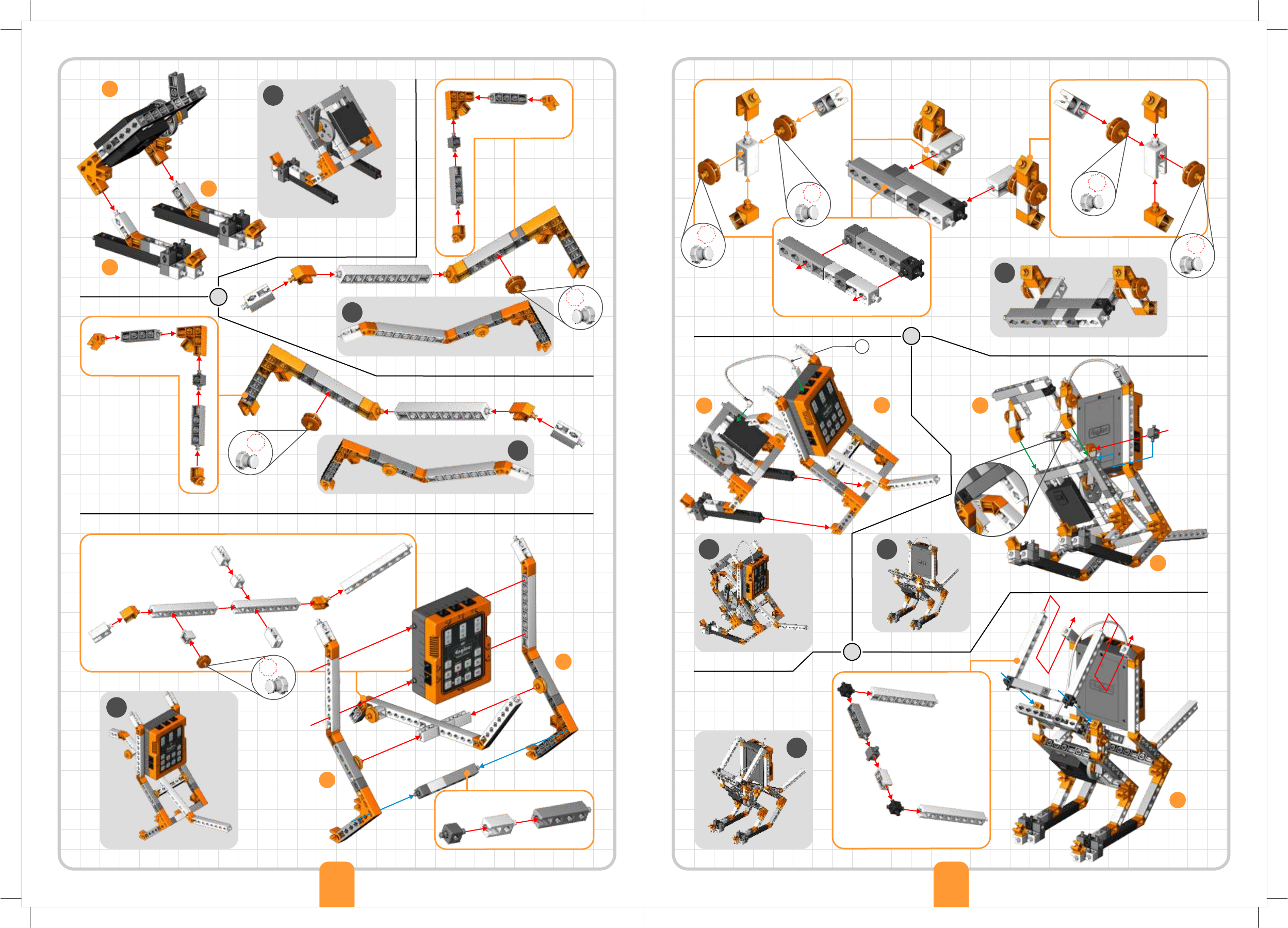
jeep car robot
01
02
03
13
x2
05
04
06
07
08
09
04
03
01
02
06
05
53 54
08
09
x4
10
11
10
07
C
3
GREEN LED
MOTOR
MOTOR
TOUCH SENSOR
11
1
GREEN LED
4
RED LED 2
RED LED
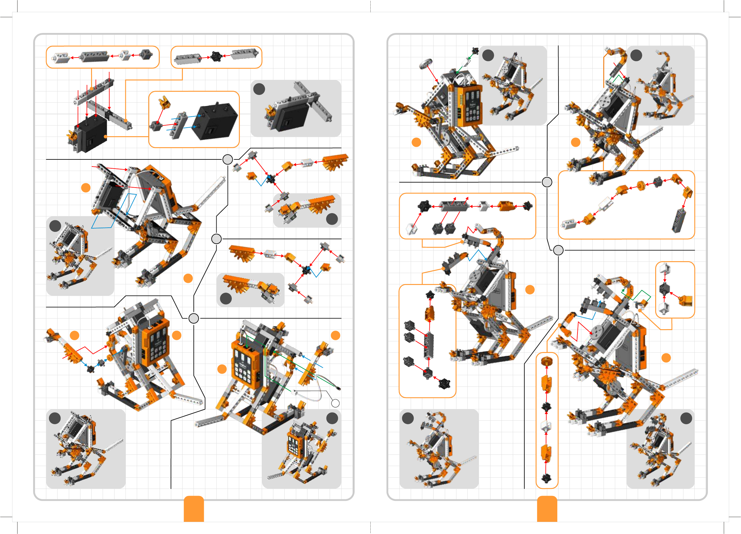
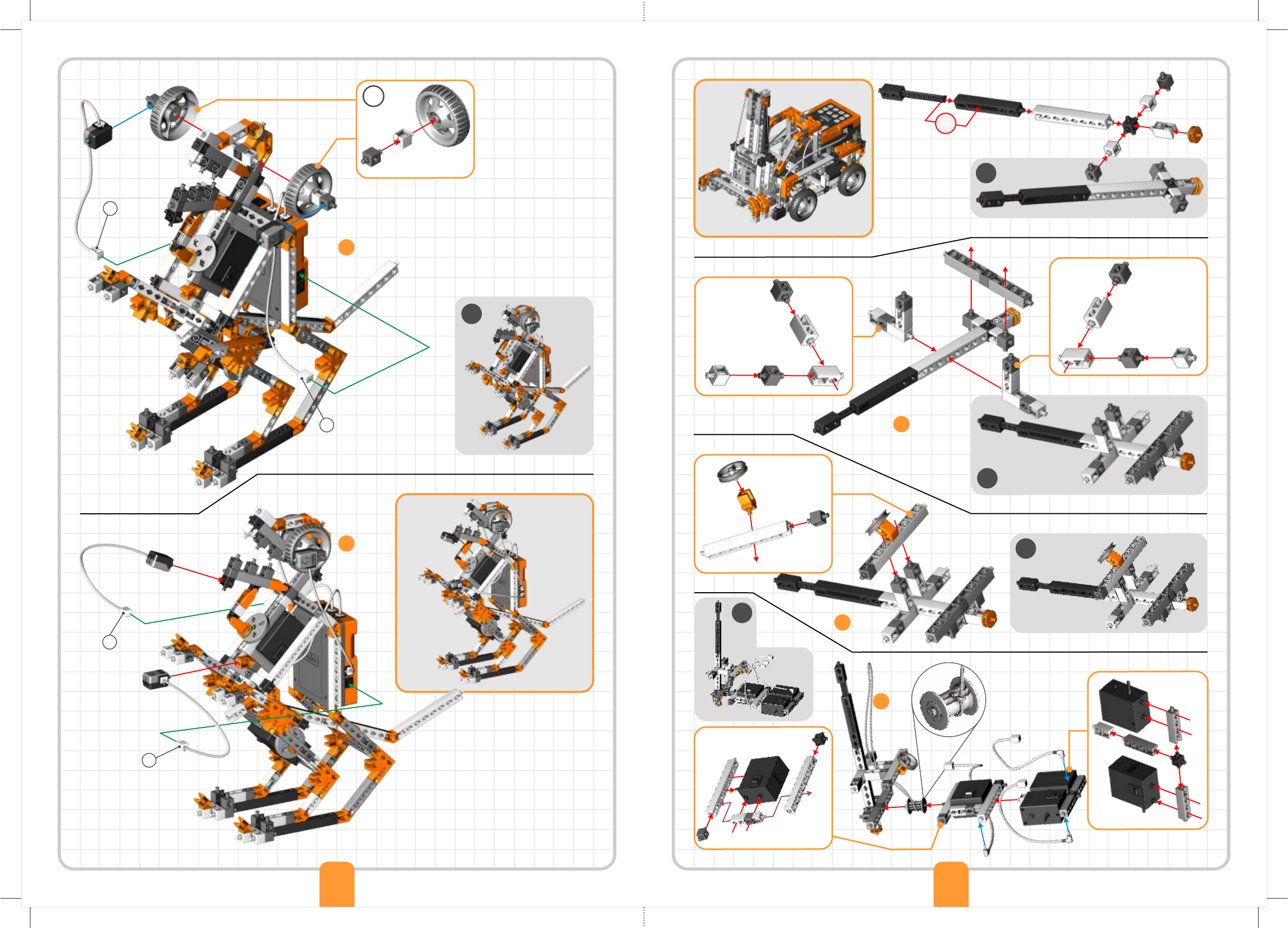
humanoid
robot
01
01
02
03 x2
x2
55 56
B
B
A
A
03
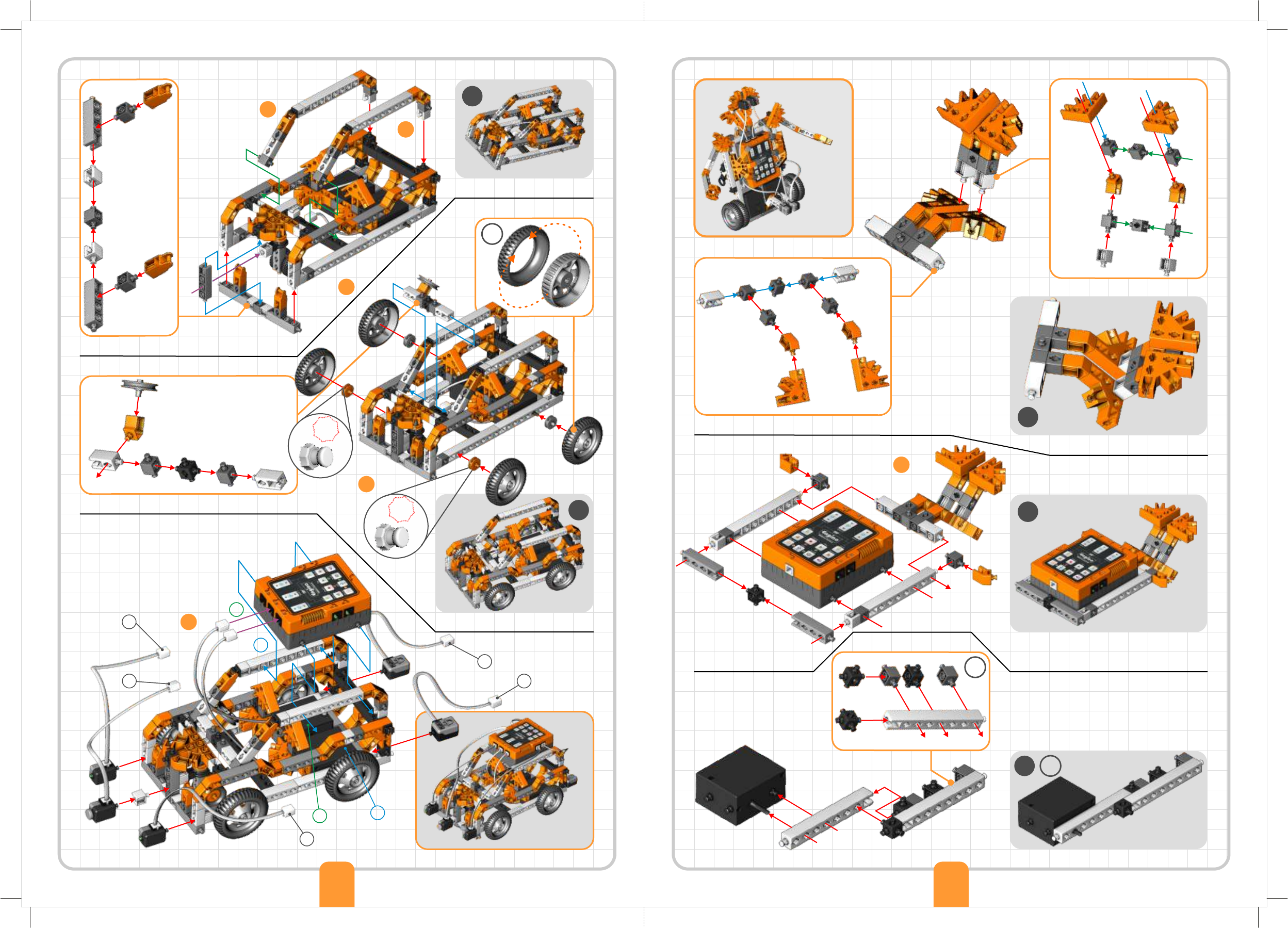
experimental
robot
01 x2
02
13
x2
04
05
02
01
03
x2
06
07
x2
Building Instructions
39 40
03
04
AMBER LED
RED LED
GREEN LED
05
x2
06
07
08
09
08
10
IR SENSOR
IR SENSOR
MOTOR
MOTOR
A
B
10
C
1
3
AMBER LED
GREEN LED
RED LED
4
IR SENSOR
dinobot
x2
01
02
13
x2
x2x2
03
01
41 42
2
IR SENSOR
04
05
06
06
05
07
02
03
03 08
08
09
09
07
04
10
11
10
A
4344
MOTOR
12
13
11
12
14
15
14 13
16 17
16
15
B
18 19
20
17 18
21
20
45 46
MOTOR
19
22
22
1
3
x2
21
2
4
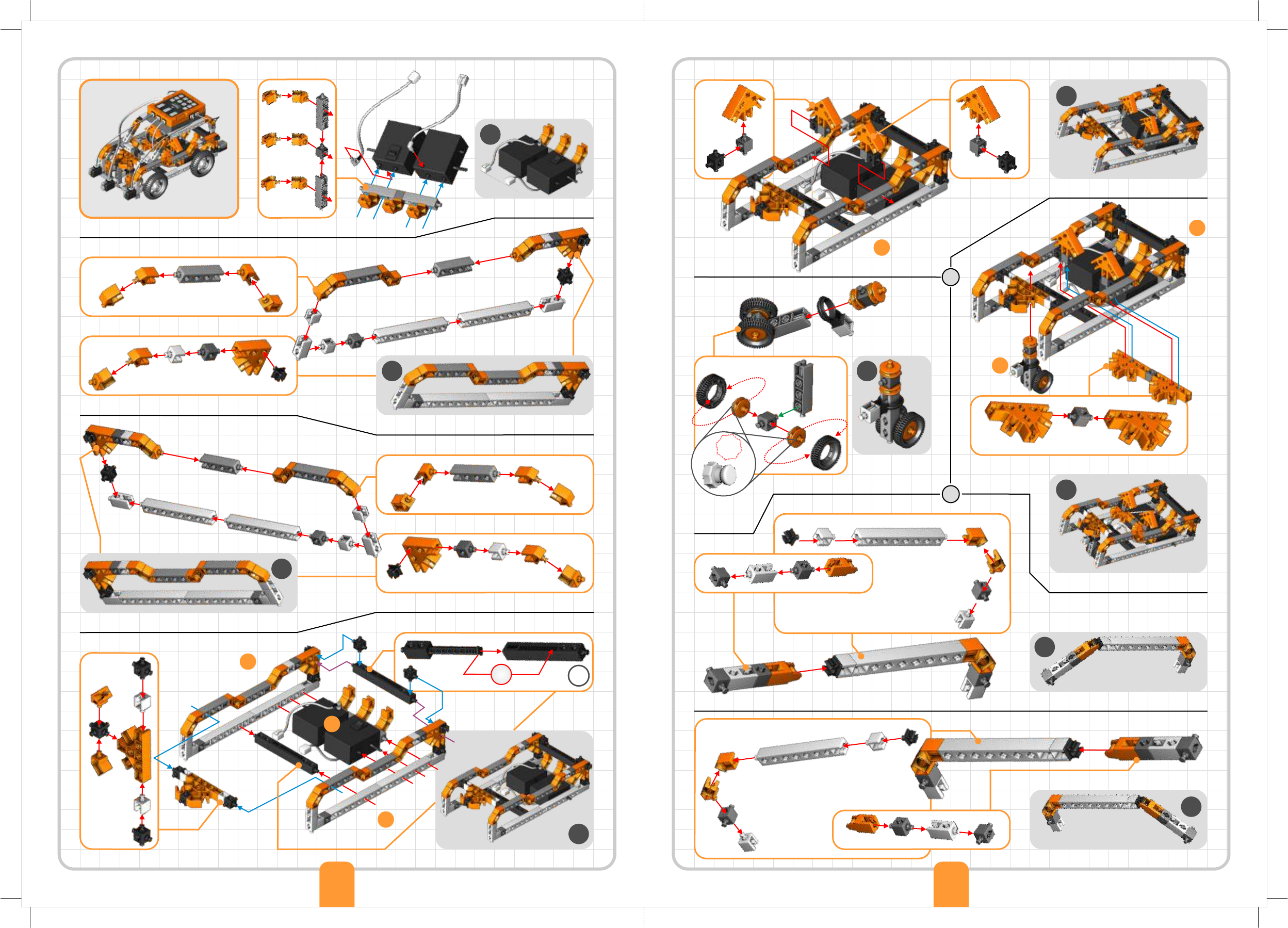
forklift
robot
6
01
02
03
03
01
02
04
47 48
IR SENSOR
IR SENSOR
GREEN LED
GREEN LED
Input
Motor 1
Motor 2
Motor 3
LED 1
LED 2
Buzzer
Exercise 2. Press “Program” (the red flashing light
indicates that the program is being recorded) and then
the necessary buttons in order to create the following
sequence:
Ÿleft fan rotates clockwise;
Ÿboth fans rotate at the same time in any direction;
Ÿred LED on;
Ÿorange and green LEDs on at the same time.
Once you finish, press the “Program” button again to
save the program and then press the “Play” button to
check if the command sequence is correct. If you press
and hold the play button for longer time the program will go
into loop (endless repeat).
Exercise 3. Note that the ERP does not record the elapsed time
between the button pushes and it just plays all the
recordings without delay. Record again, but this time
add delay between each command of exercise 2 by
pushing the “Idle Time” button. Check the results on
your model.
Exercise 4. Record the following sequence in order to simulate
traffic lights control. Don’t forget to use appropriate times:
Ÿred light on (cars stop);
Ÿred and amber light on simultaneously (cars ready to go);
Ÿgreen light on (cars go);
Ÿamber light on (cars ready to stop);
Ÿred light on (cars stop).
31
Level Of Difficulty Level Of Difficulty
®
The Engino Robotics Platform (ERP) is a robotic system
consisting of a main controller with different buttons, able to
connect with various peripherals: motors, lights and sensors.
Learn how to program the ERP device manually and create a
sequence of commands for traffic lights control.
What inputs and outputs are.
What a command sequence is.
How to program a robot manually.
How to reverse-engineer a program.
How to use the ERP simulator.
What a flow diagram is.
Procedure:
1. Find the instructions in pages 42-47 and
build the dinobot model. Lets wake it up, by
recording the sequence of exercise 1.
2. Connect the ERP device with the PC
using the USB cable. Open the Engino
Robotics Platform Pro 1.2 software and
click the Connect USB button.
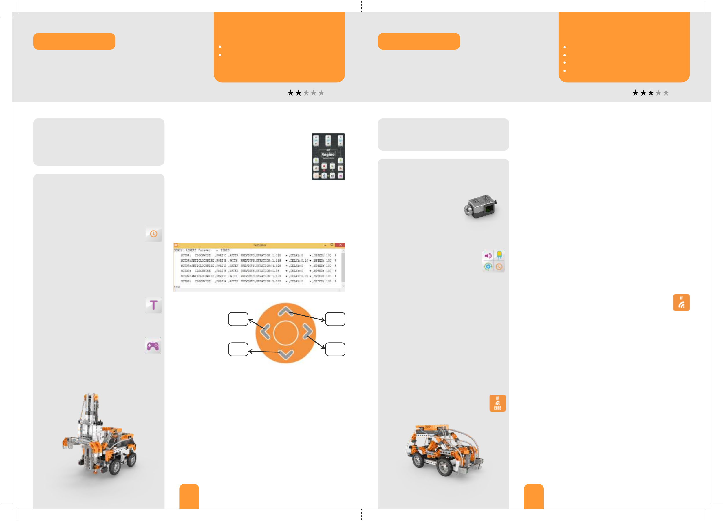
3. Click the “Receive Program” button,
so the recorded sequence is uploaded
on the computer. A vertical line of blocks
should appear, called “flow diagram”.
4. Click the “ERP Simulator view”
button and answer exercise 2.
5. Follow exercise 3 to learn more about the
action blocks and their variables on the flow
diagram. Make changes by dragging and
dropping the blocks. Right-click on each one
(motor, light, buzzer and idle), observe the
pop-up windows and complete the table.
6. Clear the screen by clicking the icon
“New”. Click the “Program” button on
the simulator (on the computer) and record
the same program as in procedure 1.
Observe what happens to the model and on
the screen.
Materials Needed:
®
- Engino Robotics PRO (STEM 70).
Materials Needed:
®
- Engino Robotics PRO (STEM70).
- Computer with ERP software downloaded
(www.enginorobotics.com) and installed.
Output
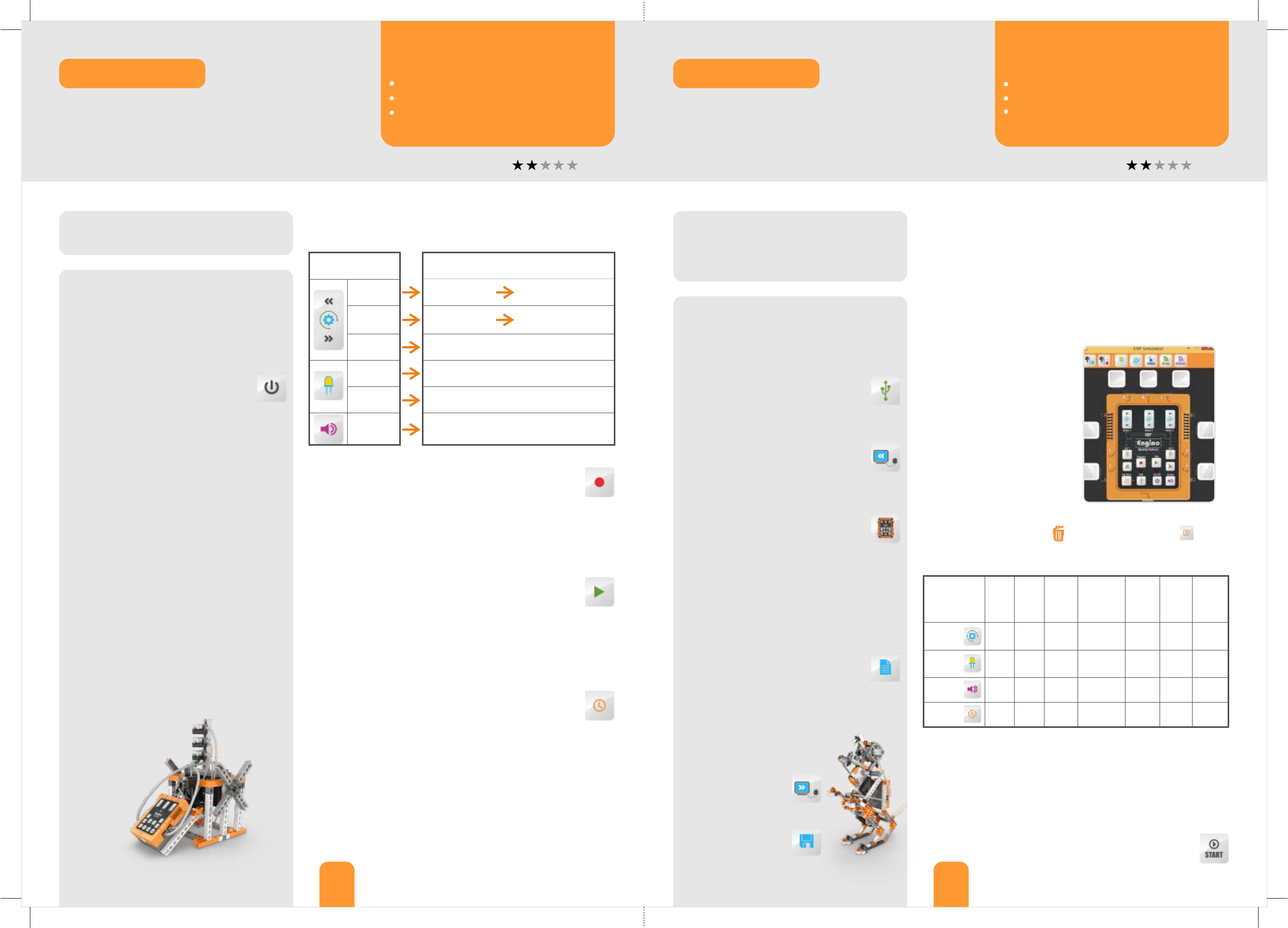
Exercise 1. Push the buttons on the ERP device (input) and
write briefly the outcome you observe on the model (output).
Exercise 3. In the flow diagram, delete the first motor icon
(drag and drop in the bin) and add an “Idle” icon
(from the left). Tick the boxes below to indicate which variables
can be changed for each action block.
Exercise 1. Using the dinobot model record the following
sequence:
Ÿboth green LEDs on at the same time (eyes open);
Ÿmotor 2 rotates clockwise (mouth opens);
Ÿmotor 2 rotates anti-clockwise (mouth closes);
Ÿmotor 1 rotates clockwise (small legs move);
Ÿbuzzer on (dinobot roars).
Upload your program on the computer (see steps 2 and 3).
Can you
modify...?
port
time
state
direction
delay
after/
with
prev.
speed
Motor
LED
Buzzer
Idle
Exercise 2. Drag and drop
the peripherals (motors,
LEDs and sensors) into the
ports of the ERP simulator,
according to the dinobot
model. Make sure that you
set them up correctly as this
affects the program and the
way your robot will behave.
Design them here as well.
Exercise 4. On the flow diagram make the following changes:
Ÿthe eyes light up at the same time and blink 2 times;
Ÿthe mouth opens and closes (use only one block);
Ÿthere is sound at the same time that the mouth moves;
Ÿthere is delay for 2 seconds and then the small legs move;
Ÿthe program should repeat for 2 times, not forever.
Tip: for this, right-click on the “start” block to choose
the number of repeats, also called loops.
A robotic system could not be complete without a programming
software. The ERP software is capable of receiving a recorded
program from the device or send a program to it. Wake up the
dinobot first manually and then through the software by using
the ERP simulator, the digital version of the actual ERP controller.
Manual Programming
ROBOTICS
Flow diagram and ERP Simulator
ROBOTICS
Learning about: Learning about:
Procedure:
1. Find the instructions in pages 39-41 and
build the experimental robot model. Make
sure you connect each cable with the correct
port. You can also twist the cables around
other parts so they do not get in the way.
Install 3 or 6 AA batteries on the back
of the ERP and power up the device
by pressing the On-Off button.
2. Press the buttons (input) on the ERP in
exercise 1 and write the results you observe
(output). On the motors, place the switch in
position II and try both buttons on the ERP.
Note that in position O the motor does not
work and in position I direction is reversed.
3. A useful function of the ERP is the ability to
record the buttons’ sequence. To test this,
press the “Program” button to record the
sequence in exercise 2. To save recording
press the “Program” button again and then
“Play” to test it. You can make many trials
until you find the corresponding buttons.
4. Did you notice that there is no delay time
between the button pushes during the
playback? Read exercise 3 to add this.
5. Use what you have learnt so far in order to
create a program concerning traffic lights
control. If you are unsure
about the correct order
you can review it in
exercise 4.
®
Engino experimental robot 32
®
Engino dinobot
7. Make changes on the flow
diagram, according to
exercise 4. Send the
program to the ERP by
clicking the “Send Program”
button and check it.
Save the program as
“dinobot” .
motor switch
in position II
motor switch
in position II
Discover:Discover: Discover:
33 34
Level Of Difficulty Level Of Difficulty
Procedure:
1. Find the instructions in pages 53-55 and
build the jeep car robot model.
2. Make sure you connect all
cables correctly. The touch
sensor must be connected
in port 3 of the ERP controller.
3. Open the ERP software and follow the
instructions in exercise 1. You can
use a function block to save the
subprogram of moving forward.
Once finished, send the program
to the ERP and test it. Save it as
“jeep forward”.
4. Add the necessary blocks on the program
you just made in order to create the program
of exercise 2. Save it as “jeep forward-turn”.
5. What happens if the model finds another
obstacle in its path? Follow the instructions of
exercises 3 and 4 to learn about the touch
sensor and the IF statement. Use this to
program your model, so that it reacts in every
obstacle it finds accordingly. Save the
program as “jeep touch-IF”
6. Create a more challenging program
with the if/else statement in
exercise 5.
Materials Needed:
®
- Engino Robotics PRO (STEM70).
- Computer with ERP software installed.
Procedure:
1. Find the instructions in pages 48-52 and
build the forklift robot model with its load.
Put motors’ switches in position II.
2. The ERP can connect wirelessly with
a smart device. To enable this feature,
push idle time button, find the ERP’s
Bluetooth network through the
EnginoRobot BT app and connect.
3. You can use the app the same way as the
actual device. Test the digital buttons and
program your model according to exercise 1.
4. Upload the program on the
software of the computer (through
USB). Follow instructions in exercise 2
about the “TextEditor” window.
5. Click on the “GamePad” button
and choose ports A-B on the pop-up
window. Click to test the arrows and
answer exercises 3 and 4.
6. Use the GamePad and the Simulator to
record the sequence described in exercise 5.
Materials Needed:
®
- Engino Robotics PRO (STEM70).
- Computer with ERP software installed.
- Smart device with Android or iOs operating
system and the EnginoRobot BT app installed.
Exercise 4. How the model turns (refer to the wheels’ direction)?
Exercise 2. Use your mouse and keyboard in order to make
necessary changes on different variables inside the TextEditor
(speed, duration, direction of motion and delay), so that the
forklift model executes its work more accurately. Circle the
changes you have made on the picture below.
Exercise 5. With the help of the GamePad and the Simulator
record the following sequence:
Ÿthe forklift robot moves forward and then turns to the right;
Ÿthe forklift robot moves forward until it finds the load;
Ÿthe teeth lift the load;
Ÿthe forklift robot turns to the left;
Ÿthe teeth lower the load.
..........................................................................................................
..........................................................................................................
..........................................................................................................
Exercise 3. Do the
wheels rotate in
the same direction
when each of the
4 arrows are
pressed? Write
YES or NO in the
boxes.
Exercise 1. On your smart device record the following
sequence:
Ÿthe forklift robot moves forward;
Ÿthe teeth lift the load;
Ÿthe forklift moves backwards;
Ÿthe teeth lower the load.
Tips: to move forward and backwards you should
tap on two motor buttons at the same time. Test
which is the correct direction for each one.
®
Engino forklift robot ®
Engino jeep car robot
®
There are many ways to control your Engino robots. One of
them is through the EnginoRobot application for smart devices
®
with a wireless Bluetooth connection. Try also the Engino
GamePad within the software and notice the difference between
manual button control and digital programming.
Decision making is what distinguishes a real robot from an
automated machine. This task is made possible by sensors which
receive feedback from the environment helping the robot to
decide what action to follow according to its program. Learn
about the touch sensor and the IF conditional statement below.
EnginoRobot app and GamePad
Learning about: ROBOTICS
Functions, touch sensor, IF and IF/ELSE statements
ROBOTICS
Learning about:
How to control your robot wirelessly.
Why controlling your robot using digital
programming is usually better than manual
programming.
How to use functions.
How to use a touch sensor.
What an IF conditional statement is.
What an IF/ELSE conditional statement is.
Exercise 1. On the computer, place the correct icons on the
ERP simulator according to the jeep car robot model. Drag and
drop the necessary blocks inside the flow diagram in order to
create the following program:
Ÿthe jeep moves forward for 3 seconds and the front LED lights
are both on at the same time.
Tip: use a “function” block to save the subprogram “move
forward”. Use the after/with previous command accordingly
and set the program to activate only once.
Exercise 2. Place an obstacle in front of the jeep car robot.
Make the necessary changes on the program of exercise
1 above so that:
Ÿthe jeep moves forward for 3 seconds and the front LED lights
are both on at the same time until it gets close to the obstacle;
Ÿthe jeep moves backwards for 1 second with all lights on;
Ÿthe jeep turns 90 degrees to the right with front LED lights on.
Tip: in order for the jeep to turn, you can either set the wheels
to turn in reverse or stop one wheel from moving altogether.
Also, conduct several tests to adjust the appropriate time
needed to turn.
Exercise 3. Drag and drop the IF statement block in the
flow diagram. Right-click on it and write below which
variables can be modified (ignore “advanced” tab).
.......................................................................................................
.......................................................................................................
Exercise 4. Use blocks inside the IF statement so that:
Ÿthe jeep moves forward continuously and the front LED lights
are both on at the same time;
Ÿif the touch sensor is pushed, then the jeep should go
backwards for 1 second with all lights on and turn 90 degrees
to the right with front LED lights on.
Tip: place the blocks that you used in exercise 2 inside the If
statement and change the program so that it repeats forever.
Exercise 5. Drop the blocks inside the IF/ELSE statement so:
Ÿthe jeep moves forward continuously and the front LED lights
are both on at the same time;
Ÿif the touch sensor is pushed, then it should go backwards for 1
second with all lights on and turn 90 degrees to the right with
front lights on. Else an interrupted beep should sound.
Discover:Discover: Discover:
35 36
Level Of Difficulty Level Of Difficulty
Materials Needed:
®
- Engino Robotics PRO (STEM70).
- Computer with ERP software installed.
- 4 x A3 white carton papers.
- Black sticky tape or black marker.
- 4 white objects for detection.
Materials Needed:
®
- Engino Robotics PRO (STEM70).
- Computer with ERP software installed.
- 4 x A3 white carton papers.
- Black sticky tape or black marker.
- 1 small water bottle (half full with 250 mL).
Procedure:
1. Find the instructions in pages 56-58 and
build the humanoid robot model.
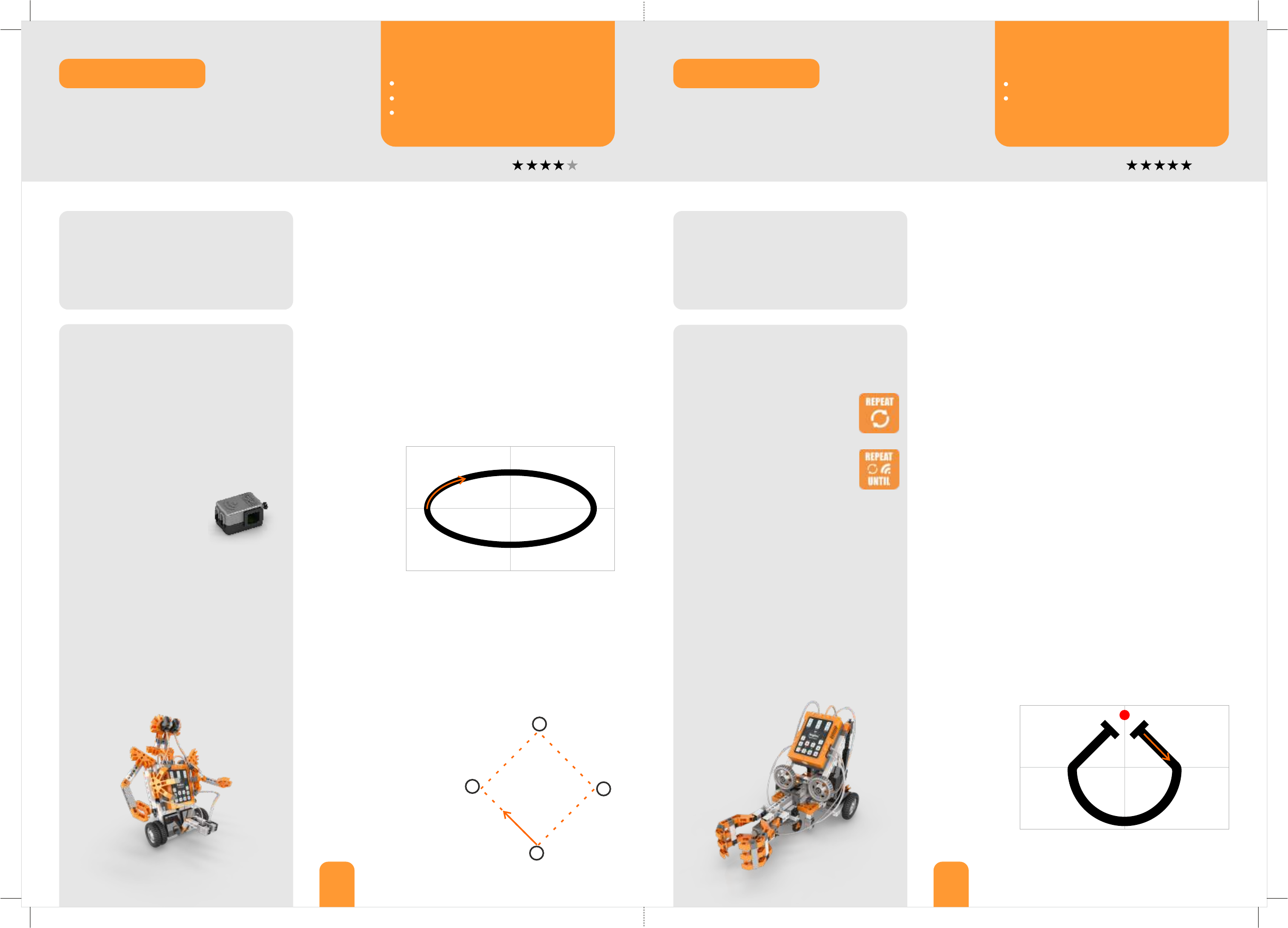
2. Stick the A3 papers together as to create a
big white rectangle. Draw a black ellipse, 5cm
thick, using a marker or sticky tape (see
picture on the right). You can also download
another path at www.enginorobotics.com
(teaching resources).
3. Open the ERP PRO 1.2
software and follow the
instructions in exercise 1,
in order to create a black
line following program.
For this, the two IR sensors should face the
ground, so turn them downwards.
4. Read exercise 2 in order to transform
your humanoid into an object detecting
robot. For this, turn the two IR sensors to
face forward. Once you create the program,
test it by placing four white objects (as tall as
the height of the sensors) as to create an
imaginary square for the robot to move
along its sides (see picture on the right).
Procedure:
1. Find the instructions in pages 59-63 and
build the grabber robot model.
2. Follow exercise 1 in order to
create a loop program using the
“repeat” block.
3. Sometimes we need a loop to be
executed continuously until a
sensor’s condition is met. Follow
exercise 2 to learn how to do this
using the “repeat until” block.
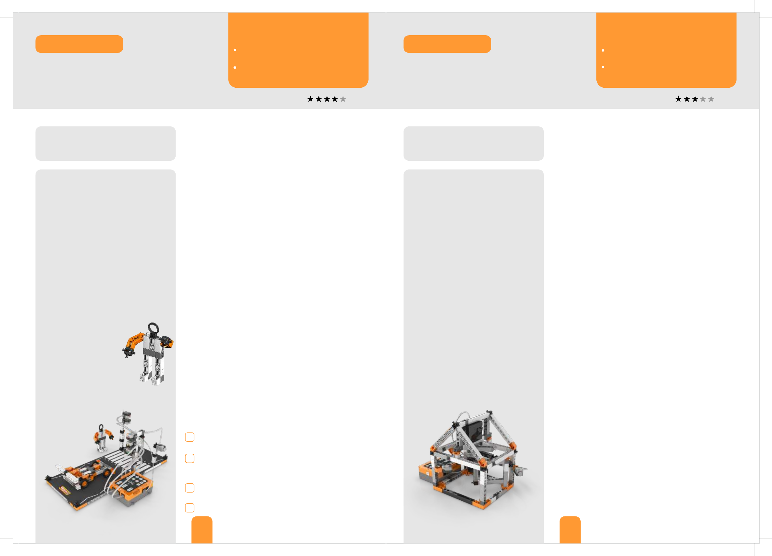
4. Stick the A3 pieces of papers together as
to create a big white rectangle. Draw a black
half circle ending with two vertical lines and a
red circle, as you see in the next picture. Or
download this at www.enginorobotics.com
(teaching resources). The grip should be in
the circle when the grabber stops on a line.
Place the bottle on the red circle.
5. Read exercise 3 in order to make a
robotic carrying device that would pick up
the bottle and take it to the other side.
Exercise 1. On the computer, place the correct icons on the
ERP simulator according to the humanoid robot model. Drag
and drop the necessary blocks inside the flow diagram in order
to create the following program:
Ÿwhile the IR sensor in port 2 detects black colour, the motor in
port B should move the humanoid forward and both lights
should be on;
Ÿwhile the IR sensor in port 4 detects black colour, the motor in
port A should move the humanoid forward and both lights
should be on.
Once you place the appropriate blocks, you will need to
configure the infrared sensors, so that they follow black
line. For this, consult the user manual under the section
“Sensors / Infrared sensor configuration” in pages 25-26.
With this program
the humanoid will
follow a black line.
In order to test
your program,
place your robot
on the black
ellipse you
created and see if
it goes around
with its lights on.
Exercise 1. On the computer, place the correct icons on the
ERP simulator according to the grabber robot model. Drag and
drop the necessary blocks inside the flow diagram in order to
create the following program:
Ÿthe grabber should move forward for 2 seconds precisely. This
should be repeated 5 times.
Ÿwhen the loop finishes the buzzer should sound for 2 seconds.
Tip: change the variable of the “start” block from “forever” to “1”
and use the “repeat” block to create the program.
Exercise 2. Drag and drop the necessary blocks inside the flow
diagram in order to create the following program:
Ÿhumanoid moves forward;
Ÿif it detects a white object with either sensor or both, the robot
should stop and warn with beeping sound and lights on;
Ÿafter 5 seconds the humanoid should turn 90 degrees to the
right in order to detect the next object.
Exercise 2. Create the following program (the grip of the
grabber should be open at the beginning):
Ÿthe grabber should move forward continuously until the touch
sensor is pressed.
Ÿwhen the touch sensor is pressed, the grabber should stop and
the grip should close with beeping sound.
Tip: change the variable of the “start” block from “forever” to “1”
and use the “repeat until” block.
Exercise 3. Create the following program (the grip of the
grabber should be open at the beginning):
Ÿwhile the IR sensor in port 2 detects white colour, the motor in
port A should move the grabber forward;
Ÿwhile the IR sensor in port 4 detects white colour, the motor in
port C should move the grabber forward;
Ÿif the touch sensor is pressed, the grip should close and grab
the bottle. Then the grabber should turn around for a specific
amount of time until it finds the black line;
Ÿthe program will be considered successful if the model reaches
the other black line.
With this program
the grabber will
follow the line by
avoiding the black
colour, pick up the
bottle and go
back. Place your
model on the
paper and see If it
works.
®
Engino humanoid robot
Tips: the angle is always the
same, so only one program is
needed for turning. To set
both or either sensor to
detect objects you must
choose the appropriate logic
gate (AND or OR). You should
also configure the sensors
again so they will activate on
object detection this time.
How to use the infrared sensor.
What a WHILE conditional statement is.
What logic gates are.
What a REPEAT statement is.
What a REPEAT UNTIL conditional
statement is.
Infrared sensors are used very frequently in robotics in two very
important applications: for distinguishing between black and
white colours and for object detection. Try both programming
challenges and learn how to configure the IR sensors, how to use
the WHILE conditional statement and logic gates.
Doing repetitive tasks with precision is one of the most important
features in programming and robotics. We can create a program
and make it repeat many times, thus entering into a “loop”. Find
out how to create loops with the ERP and how the robot can get
out of it and continue with the rest of the program.
IR sensor, WHILE statement and logic gates
Learning about: ROBOTICS
REPEAT and REPEAT UNTIL statements
ROBOTICS
Learning about:
®
Engino grabber robot
Discover:Discover: Discover:
37 38
Level Of Difficulty Level Of Difficulty
Exercise 1. On the computer, place the correct icons on the
ERP simulator according to the pedestrian crossing model. Drag
and drop the necessary blocks inside the flow diagram in order
to create the following program that simulates main traffic
lights control for the car (don’t forget to use appropriate times):
Ÿgreen light on (cars free to go);
Ÿamber light on (cars ready to stop);
Ÿred light on (cars stop);
Ÿred and amber lights on at the same time (cars ready to go);
Tip: if you put the program into loop, there is no need to add
green light as a final step, as it already exists in the beginning.
Exercise 2. Make the appropriate changes on the program of
exercise 1 in order to add the pedestrian crossing lights. These
will work in parallel with the main traffic lights so that:
Ÿwhen is green light for cars, it should be red for pedestrians;
Ÿwhen it changes to amber light for cars (ready to stop), it should
still be red light for pedestrians;
Ÿwhen it changes to red light for cars (stop), it should be green
for pedestrians (go);
Ÿwhen is red and amber lights for cars simultaneously (ready to
go), light should change to red for pedestrians.
Exercise 3. Make the appropriate changes on the program of
exercise 2 in such a way that:
Ÿthe lights interchange between the pedestrian crossing lights
and the main traffic lights should occur only if the pedestrian
pushes the button.
Tips: read the safety requirements below and adjust your
program accordingly. Remember that before the interchange,
lights should still work!
SAFETY REQUIREMENTS:
Exercise 1. It is a hot summer day! Engino-man is returning to
his house after a pleasant walk at the park. Tired as he is, he
wonders whether is it possible to install an automatic system
that would open the front door at the press of a button. Can
you help him?
On the computer, place the correct icons on the ERP simulator
according to the automated house model. Drag and drop the
necessary blocks inside the flow diagram in order to create the
following program:
Ÿif the touch sensor is pressed, the motor should open the door.
Tip: note that the motor should work accurately so that the
door will not close back.
How to program a real-life example of
pedestrian crossing.
What safety requirements should be
followed.
How to program a real-life example of an
automated house.
How to make a building more energy
efficient using robotics.
After experimenting thoroughly with all features of the Engino
Robotics Platform, you are now ready to put your knowledge into
practice! This can be achieved by programming real-life example
models, just like the one of pedestrian crossing that follows. Can
you make sure that Engino-man crosses the road safely?
Another real-life example is the automated house. One of the
main advantages of using robots is their ability to work only
when specific conditions are met. This can come in handy if we
want the air-condition of a house to work only when doors are
closed, thus saving energy. Can you simulate the same?
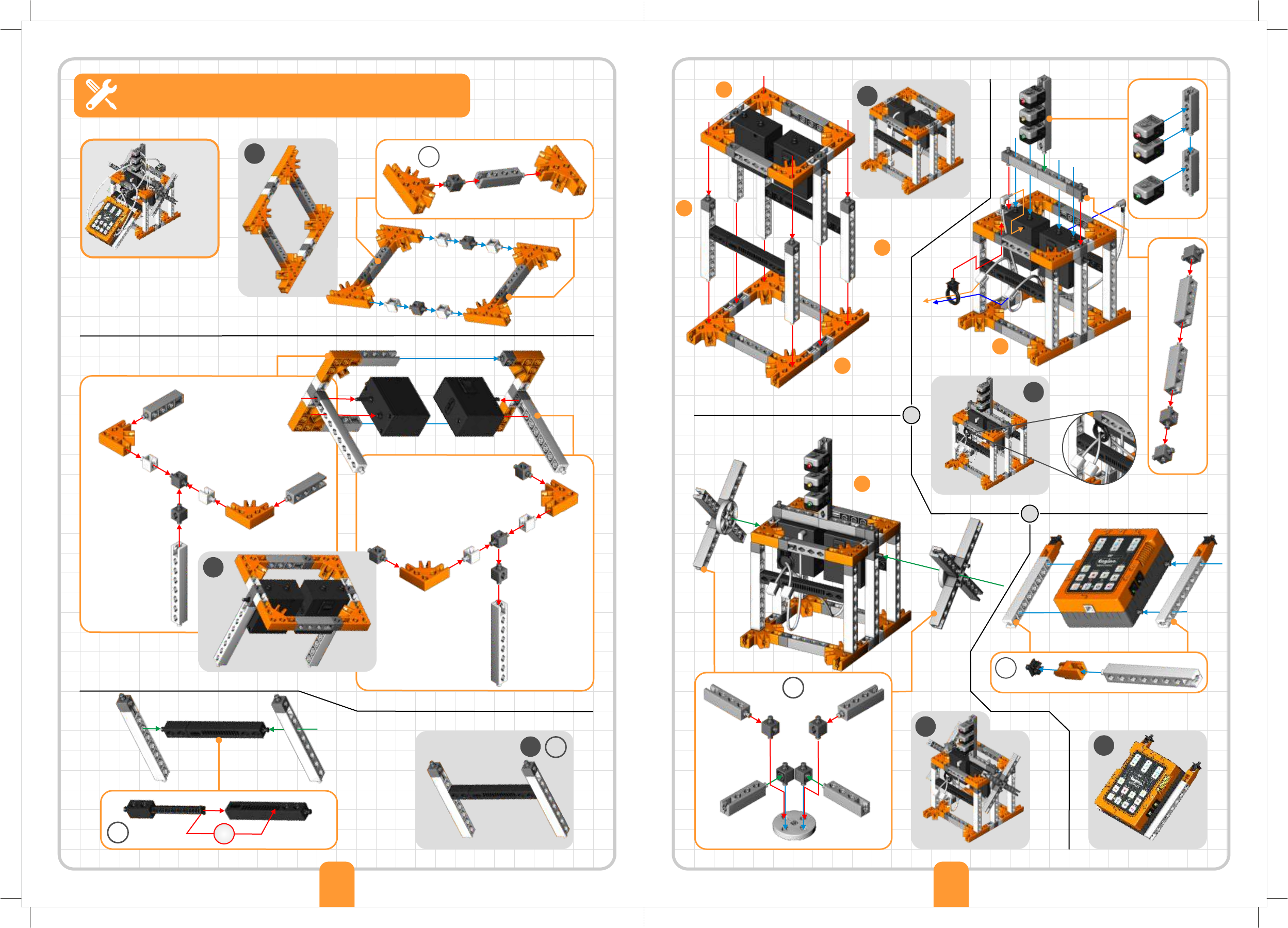
Real-life example: pedestrian crossing
Learning about: ROBOTICS
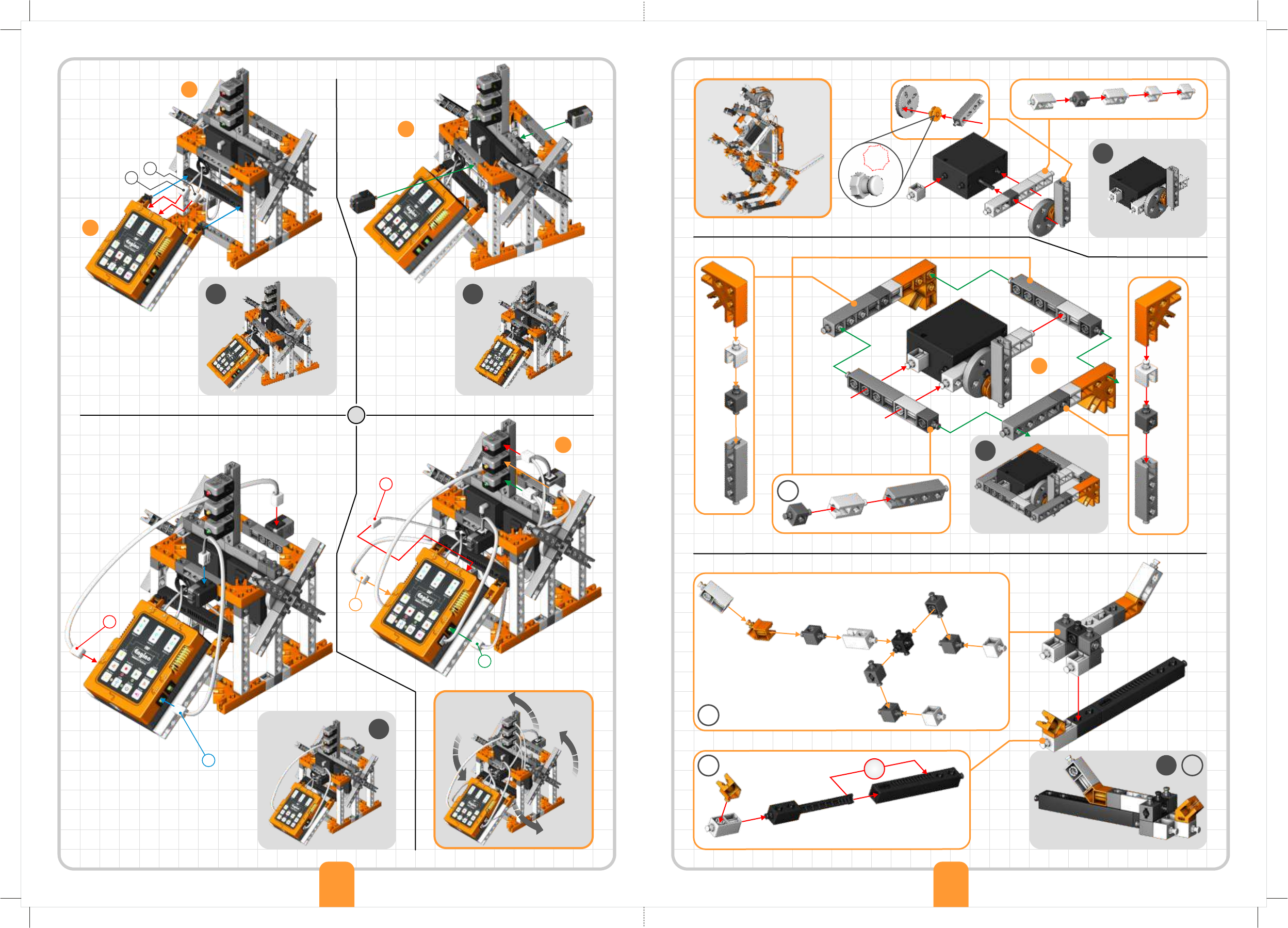
Real-life example: automated house
ROBOTICS
Learning about:
Procedure:
1. Find the instructions in pages 68-70 and
build the automated house model. With the
remaining parts you can create again an
Engino-man (page 65, step 6), who will trigger
the sensors of the house.
2. When building a house, usually the wires
are inserted inside the walls for safety and
aesthetic reasons. Twist the wires of your
model around the “columns” of the house to
simulate this, but keep the same ports.
3. Besides wiring, another problem is to
construct buildings that are as much energy
efficient as possible. And by this we mean
that the house should use power only when
is needed and at the least amount possible.
Follow exercises 1 and 2 in order to create
an energy efficient robotic house.
4. You can make your Engino model more
energy efficient structurally if you close the
walls entirely or even place an Engino solar
panel on the roof (available in solar set).
Answer question 3 about real-life houses’
efficiency, but from robotics perspective.
Materials Needed:
®
- Engino Robotics PRO (STEM70).
- Computer with ERP software installed.
®
Engino automated house
Procedure:
1. Find the instructions in pages 64-67 and
build the pedestrian crossing model. You
will find the carton paper for the road inside
your Robotics package.
2. Follow exercise 1 in order to simulate the
main traffic lights control for the cars.
3. Programming real-life traffic lights is a very
important task. People entrusted with this,
need to make absolutely sure that when one
light is green the vertical side light is always
red. This way cars or pedestrians will never
cross each other’s paths. With this in mind,
add the pedestrian crossing lights in your
existing program by following exercise 2.
4. Here comes Engino-
man wishing to cross the
road! To do this safely he
must use the pedestrian
crossing. Follow exercise
3 in order to create a
program that meets all
the safety requirements.
When you finish, tick the boxes below for
every point you got right.
Materials Needed:
®
- Engino Robotics PRO (STEM70).
- Computer with ERP software installed.
®
Engino pedestrian crossing
Is the amber light’s time adequate enough to warn car
drivers to stop?
Do the lights interchange in the correct order, not
conflicting with each other? For example, green light for
cars and pedestrians should never occur simultaneously.
Is the green light’s time adequate enough for pedestrians
to cross the road?
Did you add buzzer sound to warn pedestrians when to go?
Exercise 2. Engino-man can now enter his house in automatic
way. But why stop there? He thinks that it will be nice if there
was a way for the house to “sense” his presence so that the
door would close back and some devices would start working
after. These can be the air-condition (simulated by the fan) to
cool his house and the LED light to brighten the room. Can you
be so kind to help him again?
Make the appropriate changes on the program of exercise 1 in
such a way that:
Ÿif the IR sensor detects motion inside the house, then the door
should close back. After this, the fan should start working and
the LED light should be on.
With this program you save energy because the air-condition
works only if the door is closed, keeping the cool air inside the
house. You can make your program more energy efficient if you
add minimum time for the fan to work. In real life, air-
conditions stop when a pre-set temperature is reached.
Exercise 3. Can you think of some other ways to make real
houses more energy efficient using robotics?
..........................................................................................................
..........................................................................................................
..........................................................................................................
..........................................................................................................
Discover:Discover: Discover:
®
Engino Robotics philosophy
Five programming methods
Parallel programming
®
The Engino Robotics Platform (ERP) is specially designed for Primary and Secondary school children, taking into
account the latest technological trends and the most modern pedagogical principles of learning. Intellectual
development is approached in a spiral way, helping students to reconstruct their ideas formed based on their
existing knowledge merged with new information, acquiring higher order concepts and taking it to the next level.
The innovative ERP controller in conjunction with the patent pending ERP software are ideal for ICT teaching,
allowing various levels of robotic programming to be implemented in a fun and challenging way.
®
Two innovative ideas make the patent pending Engino Robotics Platform a unique teaching tool! Firstly, the ERP
allows five interconnected ways of programming, so the users can choose the method that suits them best
according to their age and experience. Each method is described briefly below and in more details with
programming examples in the following pages. Secondly, parallel programming (doing tasks simultaneously) has
never been easier with the introduction of the After/With Previous variable in every block of the ERP software.
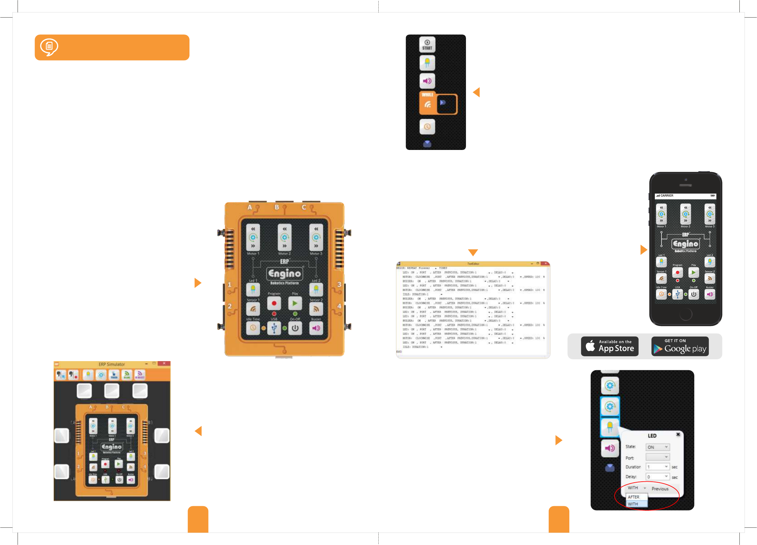
The ERP Simulator is a special window within the ERP
software that simulates the functions of the actual
controller, though the buttons in this case are digital
instead of physical. Once the computer is connected
with the ERP (through USB), the user may record a
program using the “Program” button and get a visible
feedback from the robot as before. The great
advantage of this method is that while the program is
being recorded, the commands are transferred into
the other two windows of the software: in the Flow
Diagram, as visual blocks and in the TextEditor, as lines
of text of a special pseudolanguage (not actual
programming language).
Most advanced programming languages based on text
and visual representation of commands may become
difficult as the program becomes bigger and more
complex. The Text Editor is using a “pseudolanguage”
created specifically for the ERP. It has many familiar
terms of programming languages (such as START, END,
IF etc). It is the ideal tool for introducing advanced
programming, as it allows the user to have a quick
review of the program and edit the variables easily.
Complying with modern
technological
advancements, the ERP
can also be controlled
with a smart device
(mobile or tablet) that
runs on either Android
or iOs operating system.
The user may download
the EnginoRobot BT
app, free of charge,
available on Google Play
or Apple Store. The app
simulates the actual
controller and can be
used wirelessly, once
the ERP is connected
with the smart device
over Bluetooth.
15 16
Manual ERP programming
ERP Simulator
Flow diagram
Text Editor Smart device application
The ERP device is designed in such a way that it allows
manual program recording through simple button
press. The user can easily push the “Program” button
in order to record any desired sequence of commands,
one by one or simultaneously, which is then saved on
the device and can be reviewed after by pushing the
“Play” button. This first level of programming is about
interacting physically with the learning material, using
a method (pushing buttons) that all children are
familiar with. The programming procedure provides
immediate visible feedback, enabling the user to
adjust the time and order of the commands through
unlimited number of attempts.
Once a program is created manually on the controller, it is impossible to edit
through the controller. The user must record it again in order to adjust the
commands. Also, there is no way to add advanced programming features like “If”
statements and “While” loops. This can only be done through the “Flow Diagram”,
the main programming feature of the ERP software. In this window, the user can
program complex commands and take full advantage of the robot’s capabilities and
®
sensors. The Engino robotics is designed for the gradual transition from physical
manual programming to abstract software control, by applying an innovative
reverse engineering method! The “receive” button uploads the manual program
from the device into the PC in the form of pictorial flow diagram and text! This can
be edited and fine tuned as needed. Then, the user can click the “send” button in
order to import the program back to the device for testing.
The second main innovation of Engino in educational
robotics is the function of parallel programming. The
®
Engino Robotics Platform software uses visual
programming (blocks with symbols instead of text),
which contain an innovative After/With Previous
variable that provides the parallel feature. The user
can choose between after previous if he/she wants
the command to be executed when the previous
command is finished or with previous if he/she wants
the command to be executed at the same time. The
blocks that work in parallel are joined together with a
coloured line. This reduces the complexity of
programming in a great extend, as the order of
commands become more clear and easy to formulate.
ERP Manual
17 18
®
The Engino Robotics Platform (ERP) is a robotic system consisting of a main controller with different buttons and
indicators, able to connect with various peripherals: motors, lights and sensors. The ERP is a powerful and flexible
tool that is easy to use and can connect with the rest of the Engino parts! In this manual you can find all the
necessary information about: how to program your robots with illustrated examples, the main features of the ERP
controller, how to install the ERP software, how to update the firmware, safety guidelines, tips and much more. But
first, see below the various buttons, ports and peripherals of the ERP.
Batteries: To turn on the controller you need to install
6 new AA batteries (it works also with 3 batteries
placed continuously up or down). You will need a
cross-head screw driver. Unscrew the battery cap at
the back of the controller. Place the batteries carefully
making sure that the + and - signs match those
indicated in each battery position. After you place the
batteries, screw the cap back in position if you want.
ERP controller
Manual ERP programming
MOTOR OR LED PORTS
USB PORT
for computer
connection
ON/OFF
BUTTON
IDLE TIME BUTTON
Press these buttons
to turn the motors
clockwise.
SENSOR OR LED PORTS SENSOR OR LED PORTS
LED BUTTON LED BUTTON
BUZZER BUTTON
MOTOR BUTTONS
Press this button
to light up the
connected LED.
Press this button
to light up the
connected LED.
Press this button to
play a buzzer sound.
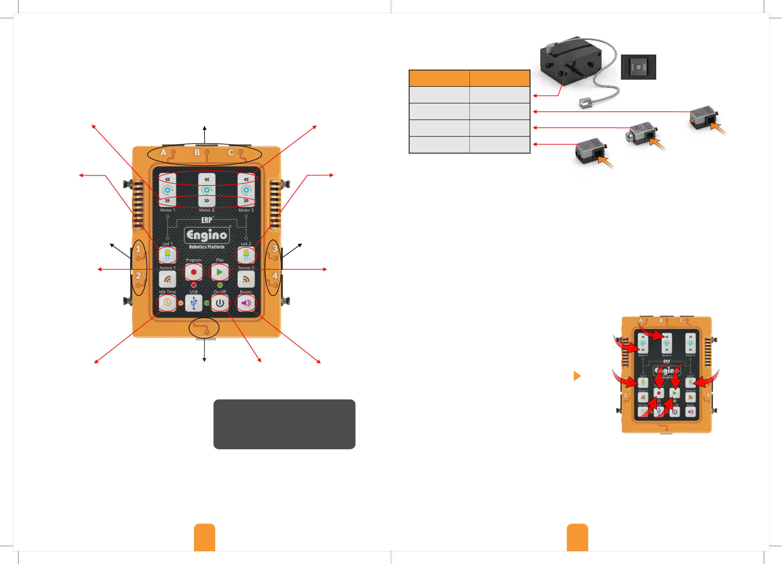
Peripherals and ports: different types of
peripherals work only in specific ports of
the ERP controller, as indicated below:
Peripherals
Ports to connect
Motors
A, B, C
LED lights
1, 2, 3, 4, A ,B, C
Touch sensors
1, 2, 3, 4
InfraRed sensors
2, 4
7
2
4
35
68
1
Connect RJ
cable here
Connect RJ
cable here
Connect RJ
cable here
Safety guidelines: Do not mix alkaline, standard or
rechargeable batteries. Non-rechargeable batteries
are not to be re-charged. Do not mix old with new
batteries. Remove dead or old batteries from the ERP
if they will not be used for a long time. Never dispose
off batteries in fire. Supply terminals are not to be
short circuited.
Instructions:
1. Press the “Program” button to begin recording (a
flashing red light should be on).
2. Hold pressed the clockwise button of the motor 1 in
port A for 3 seconds.
3. Hold pressed the button of the LED 1 in port 1 for 5
seconds.
4. Hold pressed the anti-clockwise button of the motor
2 in port B for 3 seconds.
5. Hold pressed button of the LED 2 in port 3 for 5 sec.
6. Press the “Program” button once to save the
program in memory.
7. Press the “Play” button to run the program.
8. After the program finishes you can repeat it
continuously in a loop if you hold pressed the “Play”
button for 3 seconds.
Note that the delay time between button pressing
is not recorded. While the program is in play mode
each command follows the other without any time
delay. If we want to have a time delay between steps
then we can use the “Idle Time” button. For as long as
the “Idle Time” button is pressed, interval time is
recorded between steps.
Press these buttons
to turn the motors
anti-clockwise.
MOTOR BUTTONS
PROGRAM BUTTON PLAY BUTTON
Only for manual
programming. Press this
button to start recording.
Once the red light starts
blinking the controller goes
in record mode. When you
finish, press the same button
again to store in memory.
Press the button once to
start the program. Press
and hold the button for
3 seconds to repeat the
program in a loop.
Bluetooth must be turned off in order to
turn off the device smoothly. Also, make
sure that the USB cable is not connected.
The ERP, once switched ON, can be operated manually by pressing the various buttons in real time. To begin manual
recording press the “Program” button once. The red flashing light indicates that the ERP is in record mode. In order
to create a programming sequence, press the buttons of the LEDs, Motors, Buzzer or Idle Time at any desired order,
either separately or simultaneously. Each step is recorded for a period of time that the button is being pressed.
When the programming procedure is finished, press again the “Program” button to save the program in the
controller’s memory. Press “play” to start the program; if you hold it for 3 seconds the program will repeat in a loop.
Note that the device can save only one program in its memory. You can also operate the ERP without setting it
in record mode; just press the buttons and it will work as a controller in order to see how the various outputs work.
Recording example 2: The ERP also allows many
commands to play simultaneously. For example you
can press two or more buttons at the same time and
they will play together. Repeat the same sequence as
in example 1, but this time follow commands 2 and 3
simultaneously. Then press and hold the “Buzzer” for 2
seconds; then press the “Idle Time” for 5 seconds and
carry out commands 4 and 5 simultaneously. Finally,
save and play (commands 6, 7 and 8).
ATTENTION:
This button has two functions:
- it adds idle time during manual programming;
- press once to activate the Bluetooth when the
controller is switched on (but not in recording or
play mode). Open the EnginoRobot BT app,
find the ERP Bluetooth network and connect.
Note that if the ERP is not connected with any
Bluetooth device within 1 minute, it will turn off
to save energy.
Recording example 1: Connect 2 motors in each of the ports A and B and 2 LED lights on ports 1 and 3. The
peripherals will run for as long as their buttons are pressed. You can try to press the Buzzer as well. For the
program, the motor in port A should move clockwise for 3 seconds, the LED in port 1 to light up for 5 seconds, the
motor in port B to turn anti-clockwise for 3 seconds and the LED in port 3 to light up for 5 seconds.
The motor does not work if
the switch is on position O. In
position II the motor works in
the direction of the ERP
controller. In position I the
direction is reversed. Motors
do not need extra batteries to
work.