ERG Transit Systems CID1B Card Reader User Manual APPENDIX B
ERG Transit Systems Card Reader APPENDIX B
User Manual

FCC ID: Q47 - CID1 B Report No. T31109_F Appendix H
APPENDIX H
OF
TEST REPORT T31109_F
TEST SAMPLE TECHNICAL(USER) MANUAL
FCC ID: Q47-CID1D
Manufacturer: ERG Ltd
Test Sample: Card Interface Device (CID1B)
Model: 18186
Serial No: 03222860
Date: 13th November 2003
EMC Technologies Pty Ltd
A.C.N. 057 105 549
16/6 Gladstone Rd
Castle Hill, NSW 2154
Ph: + 612 9899 4599
Fax: + 612 9899 4019
email: syd@emctech.com.au
HTTP: www.emctech.com.au
This material is confidential to ERG and may not be disclosed in whole or in part to any third party nor used in any
manner whatsoever other than for the purposes expressly consented to by ERG in writing.
This material is also copyright and may not be reproduced, stored in a retrieval system or transmitted in any form or
by any means in whole or in part without the express written consent of ERG.
Device Product Group
CID1B Field Maintenance Manual
Document No: DPG-00253 Category: 434 Revision: 1
ERG
Approvals Author Process Manager Manager
Name: William Rivera Gino Bertino
Signature:
Date:

Device Product Group Security Level 3 CID1B Field Maintenance Manual
DPG-00253 ERG Confidential © ERG 2003 Page 2 of 21
Revision 1 / 13 Nov 03
Document History
Revision Revision
Date Description Author
0.1 11 Nov 03 Initial Draft William Rivera
1.0 13 Nov 03 Initial Release William Rivera

Device Product Group Security Level 3 CID1B Field Maintenance Manual
DPG-00253 ERG Confidential © ERG 2003 Page 3 of 21
Revision 1 / 13 Nov 03
FCC Compliance Statement
This device complies with Part 15 of the FCC rules. Operation is subject to the following
two conditions: (1) This device may not cause harmful interference, and (2) this device
must accept any interference received, including interference that may cause undesired
operation.
This equipment has been tested and found to comply with the limits for a Class B digital
device, pursuant to Part 15 of the FCC Rules. These limits are designed to provide
reasonable protection against harmful interference in a residential installation. This
equipment generates, uses and can radiate radio frequency energy and, if not installed
and used in accordance with the instructions, may cause harmful interference to radio
communications. However, there is no guarantee that interference will not occur in a
particular installation. If this equipment does cause harmful interference to radio or
television reception, which can be determined by turning the equipment off and on, the
user is encourage to try to correct the interference by one or more of the following
measures:
Reorient or relocate the receiving antenna.
Increase the separation between the equipment and receiver.
Connect the equipment into an outlet on a circuit different from that to which the
receiver is connected.
Consult the dealer or an experienced radio/TV technician for help.
The CID1B was submitted and a grant of authorisation received from the FCC under the
intentional radiator requirements of part 15, Subpart C.
Warning: Any changes or modifications not expressively approved by ERG Transit
Systems could void the user’s authority to operate this equipment

Device Product Group Security Level 3 CID1B Field Maintenance Manual
DPG-00253 ERG Confidential © ERG 2003 Page 4 of 21
Revision 1 / 13 Nov 03
Table of Contents
1 INTRODUCTION .................................................................................................................................. 5
1.1 PURPOSE............................................................................................................................................ 5
1.2 SCOPE................................................................................................................................................ 5
1.3 TERMINOLOGY .................................................................................................................................... 5
2 OVERVIEW........................................................................................................................................... 6
2.1 MAINTENANCE STRUCTURE OVERVIEW ................................................................................................ 6
2.2 FIRST LINE MAINTENANCE ................................................................................................................... 6
2.3 SECOND LINE MAINTENANCE ............................................................................................................... 7
2.4 THIRD LINE MAINTENANCE................................................................................................................... 7
3 CID1B DEVICE DESCRIPTION ........................................................................................................... 8
3.1 OPERATIONAL MODES......................................................................................................................... 9
4 TROUBLESHOOTING AND DIAGNOSTIC TESTING ...................................................................... 10
4.1 TROUBLESHOOTING GUIDE ................................................................................................................ 10
4.2 DIAGNOSTIC TESTING........................................................................................................................ 10
4.2.1 Start-up ................................................................................................................................... 11
4.2.1.1 Power on Self-Test........................................................................................................................11
4.2.2 Maintenance Mode Testing..................................................................................................... 12
5 PREVENTATIVE MAINTENANCE..................................................................................................... 13
5.1 SAFETY ............................................................................................................................................ 13
5.2 RETRIEVING DATA FROM DEVICES ..................................................................................................... 13
5.3 DAILY MAINTENANCE......................................................................................................................... 13
5.4 WEEKLY MAINTENANCE..................................................................................................................... 13
5.5 MONTHLY MAINTENANCE................................................................................................................... 13
5.6 YEARLY MAINTENANCE...................................................................................................................... 13
5.7 SPECIAL MAINTENANCE..................................................................................................................... 14
6 LINE REPAIR PROCEDURES........................................................................................................... 15
6.1 GENERAL.......................................................................................................................................... 15
6.2 DIAGNOSTIC TESTING........................................................................................................................ 15
7 MOUNTING AND REMOVING THE CID1B....................................................................................... 16
7.1 CID1B MOUNTING ............................................................................................................................ 16
7.2 REMOVAL OF CID1B ......................................................................................................................... 18
8 CID1B AUDIO/VISUAL INDICATORS............................................................................................... 20
List of Tables
TABLE 1: TERMINOLOGY.................................................................................................................................. 5
TABLE 2: TROUBLESHOOTING CHART............................................................................................................. 10
TABLE 3: AUDIO/VISUAL INDICATORS TYPICAL VALUES ................................................................................... 20
TABLE 4: LED FUNCTIONALITY ...................................................................................................................... 21
List of Figures
FIGURE 1: CID1B CARD INTERFACE DEVICE.................................................................................................... 6
FIGURE 2: CID1B FRONT AND REAR VIEW ........................................................................................................ 8
FIGURE 3: CID1B MOUNTING CRADLE............................................................................................................. 8
Device Product Group Security Level 3 CID1B Field Maintenance Manual
DPG-00253 ERG Confidential © ERG 2003 Page 5 of 21
Revision 1 / 13 Nov 03
1 Introduction
1.1 Purpose
This manual describes the field maintenance procedures (refer to Section Maintenance
Structures Overview) for the Card Interface Device (CID1b).
1.2 Scope
The manual provides a technical description of the removal, replacement and
maintenance procedures for the CID1b. Information contained within this manual allows
on site, first line maintenance only.
Note: The maintenance procedures of the CID1b described in this manual may vary
slightly between operators to cater for their individual requirements.
1.3 Terminology
The following table contains a list of Equipment Terminology and their meanings.
Table 1: Terminology
Term Definition
CID Card Interface Device
CSC Contactless Smart Card
DC Driver Console
Hz Hertz
LCD Liquid Crystal Display
LED Light Emitting Diode
MTTR Mean Time To Repair
Patron Passenger or customer
PCB Printed Circuit Board
PID Patron Information Display
POST Power On Selt-Test
Device Product Group Security Level 3 CID1B Field Maintenance Manual
DPG-00253 ERG Confidential © ERG 2003 Page 6 of 21
Revision 1 / 13 Nov 03
2 Overview
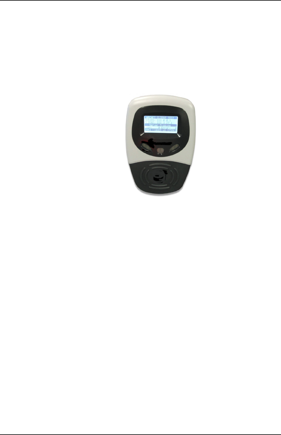
The Card Interface Device (CID1B) is used when passengers board a vehicle in order to
validate a contact-less smart card. Passengers are able to use their smart card to travel
with various operators on all modes of public transport including train, light rail, bus, and
ferry services.
Contact-less smart cards are credit-card sized, battery-less, encrypted, portable memory
devices that have the facility to store patron information and a value of currency within
their electronic "Purse". The operator can assess the value and deduct the payment for
any trips electronic "Purse".
Figure 1: CID1B Card Interface Device
2.1 Maintenance Structure Overview
Maintenance activities for the CID1B are divided into two categories:
1. First Line Maintenance
2. Third Line Maintenance
Note: Second Line Maintenance is not applicable to the CID1B. (Refer to 2.2.)
Factors that distinguish the two categories include:
The level of skill required.
Complexity of test equipment and tools required.
The need for workshop facilities.
The feasibility of maintenance activities being performed on-site.
2.2 First Line Maintenance
As a rule, field maintenance is performed on-site and does not require workshop facilities,
specialised test equipment or tools. Only basic technical knowledge is required, and work
is performed according to set procedures. In most cases the Transit Operators will
provide First Line maintenance.
Typical field maintenance activities include:
Periodic and preventative maintenance, e.g. cleaning, lubricating, replacement
of consumables.
Removal and installation of equipment.
Removal and installation of sub-assemblies using standard tools and methods.

Device Product Group Security Level 3 CID1B Field Maintenance Manual
DPG-00253 ERG Confidential © ERG 2003 Page 7 of 21
Revision 1 / 13 Nov 03
Low level commissioning of equipment, for example, loading of software, setting
of equipment parameters (like time) and machine numbers. In short, any
operation that does not require adjustments and calibrations based on
measurements and technical judgement.
Periodic monitoring, recording and reporting of equipment performance data.
Identification and assessment of fault and damage indications and the
preparation of fault reports.
Completion of Equipment Service Reports and return of faulty equipment to the
Service Bureau repair depot.
2.3 Second Line Maintenance
The Second Line maintenance is defined as any Service Bureau action necessary to
diagnose and restore any out of service equipment where First Line maintenance and/or
Transit Operator Telephone support was unsuccessful in resolving the problem. The
Service Bureau will be responsible for providing local on-line and on-call maintenance
support to the Transit Operators.
Typical Second Line maintenance activities include:
On-line telephone support by technically trained Customer Service
Representatives.
On-call field support by the Service Bureau Field Service Team.
Removal and installation of defective devices/modules.
Commissioning of equipment, including adjustments, calibrations and the use of
software diagnostic tools.
Note: The CID1B does not require Second Line Maintenance. This section is included for
information only.
2.4 Third Line Maintenance
Activities of this category are normally performed in workshop facilities and require a
degree of technical knowledge and some specialised tools. Valued judgement and
decisions as to the usability and serviceability of equipment may be required.
Typical shop maintenance activities include:
Periodic and preventive maintenance including the dismantling and re-assembly
of subassemblies, soldering, crimping and assembly of connectors.
Fault finding to functional block level, using electronic test equipment and
standard fault finding methods.
Identification and exchange of faulty PCBs.
Functional testing and certification of equipment.
Commissioning of equipment, including adjustments, calibrations and the use of
software diagnostic tools.
Monitoring, recording and reporting of equipment performance.
Contributions to measures aimed at the improvement of the
performance/reliability of equipment, e.g. Total Quality Management.
Device Product Group Security Level 3 CID1B Field Maintenance Manual
DPG-00253 ERG Confidential © ERG 2003 Page 8 of 21
Revision 1 / 13 Nov 03
3 CID1B Device Description
The patron is required to present (tag) the smart card on both entry and exit via this
device. The fare is deducted from the smart card on exit.
On a flat fare system, only one (tag) on entry is required.
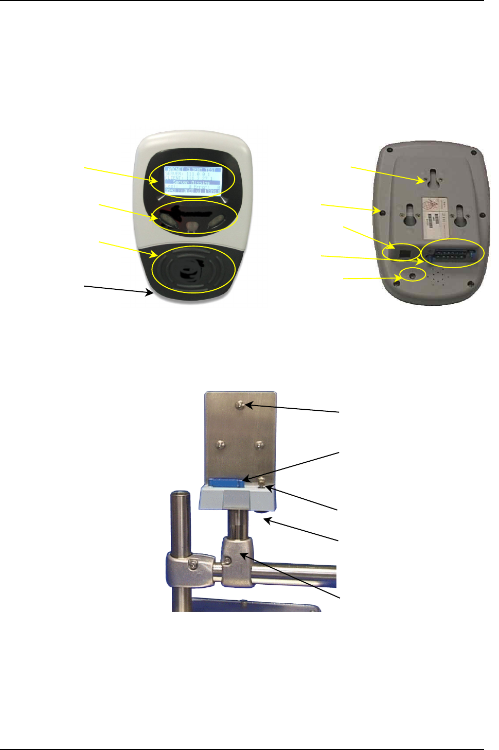
A CID1B consists of the following components (Figure 2):
Figure 2: CID1B front and rear view
The CID1B is mounted on a dedicated mounting cradle located adjacent to entry and exit
positions on each vehicle. The mounting cradle consists of:
Figure 3: CID1B Mounting Cradle
The CID1B consists of the following components.
Patron Information Display (PID)
Light Emitting Diode (LED) indicators and loudspeaker
Smart card target and reader/writer
Outer casing
Communication and diagnostic ports (not shown)
Mounting
Bolts (3)
Connector
Keybolt
Under base
Key Entry Point
T-Arm
Mounting Bolt Slots
(3)
Outer Casing
Screws (6)
Keybolt Opening
Connectors
Address Selector
Patron Information
Display (PID)
Transaction Status
Indicators (LEDs)
Smart Card Target
Outer Casing

Device Product Group Security Level 3 CID1B Field Maintenance Manual
DPG-00253 ERG Confidential © ERG 2003 Page 9 of 21
Revision 1 / 13 Nov 03
Internal electronic printed circuit boards (not shown)
The CID 1B is mounted on a dedicated mounting cradle located adjacent to
entry and exit positions on each vehicle.
3.1 Operational Modes
The CID1B can operate in one of the following five operational modes:
Start-up Mode.
In-service Mode.
Employee Logon Mode.
Maintenance Mode.
Out-of-service Modes.

Device Product Group Security Level 3 CID1B Field Maintenance Manual
DPG-00253 ERG Confidential © ERG 2003 Page 10 of 21
Revision 1 / 13 Nov 03
4 Troubleshooting and Diagnostic Testing
4.1 Troubleshooting Guide
If a problem is detected during the operation of the CID1B, turn the device off and on. If
after rebooting the problem still exists, remove and replace the CID1B.
In general, the following problems are possible during the operation of a CID1B:
Table 2: Troubleshooting Chart
Problem Description Repair
Procedure Successful Repair Unsuccessful Repair
No display Perform Start-up Proceed with normal
operation Remove and replace
CID1B (see 7 Mounting).
Displays incorrect
information
(see Appendix A)
Perform Start-up Proceed with normal
operation Remove and replace
CID1B (see 7 Mounting).
LEDs do not illuminate Perform Start-up Proceed with normal
operation Remove and replace
CID1B (see 7 Mounting).
LEDs illuminate
incorrectly
(see Appendix A)
Perform Start-up Proceed with normal
operation Remove and replace
CID1B (see 7 Mounting).
Speaker does not sound Perform Start-up Proceed with normal
operation Remove and replace
CID1B (see 7 Mounting).
Speaker sounds
incorrectly
(see Appendix A)
Perform Start-up Proceed with normal
operation Remove and replace
CID1B (see 7 Mounting).
CSC reader/writer does
not respond to card tag Perform Start-up Proceed with normal
operation Remove and replace
CID1B (see 7 Mounting).
4.2 Diagnostic Testing
The diagnostic testing consists of two testing methods:
Power on self-test performed at start-up.
Maintenance mode testing.
The following sections describe the diagnostic testing procedures of the CID1B.

Device Product Group Security Level 3 CID1B Field Maintenance Manual
DPG-00253 ERG Confidential © ERG 2003 Page 11 of 21
Revision 1 / 13 Nov 03
4.2.1 Start-up
Start-up diagnostic testing is performed whenever power is applied to the CID1B.
The purpose of the start-up diagnostic testing is to confirm the correct operation of the
CID1B Main board and its peripheral devices before the CID1B is placed In Service. On
Start-up the CID1B will cycle through operating the LCD, speakers, LEDs and CSC
reader/writer. The diagnostic messages are displayed on the screen.
The CID1B performs the following actions whenever it is powered up or is reset:
1. Power is applied to the CID1B and the CPU commences operation.
2. The CID1B performs a Power on Self-Test. See Section 4.2.1.1.
Note: The CID1B enters the Out of Service (permanent) mode if any of self-tests fails.
3. If the CID1B has been powered off or reset for less than a configurable period of
time, it enters into the mode of active operation before being reset or turned off,
otherwise it enters the Out Of Service temporary mode.
4.2.1.1 Power on Self-Test
Self-Test is performed whenever the CID1B is powered up, or reset.
The Self-test sequence is as follows:
1. Main PCB checks.
2. Memory checks.
3. CSC Reader checks.
4. If the CID1B internal tests fail the following sequence of events will occur:
– The CID1B goes into Out Of Service (Permanent) Mode.
– The CID1B logs the relevant error code.
5. If the CID1B internal tests pass the following sequence of events will occur:
– The CID1B sounds the O.K. tone.
– The CID1B enters into Out Of Service (Temporary) Mode.
The Out-of-service Modes are:
Permanent - when a CID fails its Power on Self-Test (POST), it can not be
operated and requires maintenance.
Temporary – when a CID passes its Power on Self-Test (POST), it goes into
standby mode ready for operation.

Device Product Group Security Level 3 CID1B Field Maintenance Manual
DPG-00253 ERG Confidential © ERG 2003 Page 12 of 21
Revision 1 / 13 Nov 03
4.2.2 Maintenance Mode Testing
Maintenance mode enables maintenance personnel to perform routine self test functions.
This mode can be entered and exited by tagging a special maintenance smart card on
the card reader.
When entering Maintenance mode, the CID1B display indicates that it is in Maintenance
mode.
The CID1B can be placed into Maintenance Mode by tagging a Maintenance card.
The CID1B performs a set of self-tests and displays the result of these tests.
The following self-tests are:
1. The CID1B displays a Maintenance Mode text message and turns off all LEDs.
You have 5 seconds to tag your card again to EXIT maintenance mode.
2. The CID1B displays software version and date.
3. The CID1B displays system information, i.e. fare information etc.
4. The CID1B tests the CSC reader/writer.
5. The CID1B tests the LCD screen by turning the pixels on then off.
6. The CID1B tests the background contrast of the LCD.
7. The CID1B tests the brightness of the LCD.
8. The CID1B tests the LEDs by turning them on one at a time then all three at the
same time; the LEDs test is repeated a second time.
9. The CID1B tests the Speaker by sending beeps to the speaker. These beeps will
last for 15 seconds and the level will gradually increase from (0 to 260).
10. At the completion of the Maintenance Mode self tests the CID1B will exit to Out-Of-
Service mode.
Note: Note: During a self-test, if a Maintenance card is placed over the CSC reader/writer the
CID1B will exit to Out-Of-Service mode.

Device Product Group Security Level 3 CID1B Field Maintenance Manual
DPG-00253 ERG Confidential © ERG 2003 Page 13 of 21
Revision 1 / 13 Nov 03
5 Preventative Maintenance
The Daily Maintenance checks described below are easily carried out in-situ and are
recommended for the continued efficient operation of the CID1B. Daily checks are best
carried out at the end of the last shift of the day. Weekly and monthly checks are not
required.
5.1 Safety
All maintenance work is to be performed to recognised industry standards, using
appropriate protective clothing where necessary and tools suitable for the task.
When a bus is in service, cradles must not be left empty and should have a device
mounted at all times.
Personnel attempting to diagnose or repair faults in the electrical wiring are to be trained
and qualified in the appropriate electrical codes of practice and are to work in accordance
with those codes.
5.2 Retrieving Data from Devices
The CID1B carries data recorded during each bus trip that has commercial value to the
bus service provider. It is important that this information is retrieved from the device
before any maintenance is carried out which may destroy the data.
5.3 Daily Maintenance
The daily maintenance procedure is as follows:
1) Check the exterior of the CID1B and cables for any signs of physical damage.
2) Check the security of the equipment in the cradle and the lock.
3) Power up the On-Board equipment and check the operation of the LCD display,
LEDs and loudspeaker.
4) Check the CID1B is positioned correctly to allow the patron to see the PID clearly.
5) Remove any dirt or dust from the surface of the equipment with a damp cloth.
Warning: Use of abrasive cloths, cleansers and concentrated cleaning solvents will cause
permanent damage to the exterior surfaces of the unit.
5.4 Weekly Maintenance
There is no requirement for weekly maintenance.
5.5 Monthly Maintenance
There is no requirement for monthly maintenance.
5.6 Yearly Maintenance
There is no requirement for yearly maintenance.

Device Product Group Security Level 3 CID1B Field Maintenance Manual
DPG-00253 ERG Confidential © ERG 2003 Page 14 of 21
Revision 1 / 13 Nov 03
5.7 Special Maintenance
Every two years the CID1B must be removed and returned to a Repair Depot for internal
maintenance including battery replacement. The cradle can be checked and cleaned at
this time.
1. Remove the CID1B from its mounting cradle (see Section 7.2).
2. Pack the CID1B for shipping to a Repair Depot.
3. Check the cleanliness of the cradle. Clean if required with a damp cloth. Dry
completely before replacing a unit.
4. Inspect the contacts in the connector for dirt and/or damage. Clean contacts with a
soft brush.
5. Install replacement CID1B unit (see Section 7.1).
6. Power up the On-Board equipment and check the operation of the LCD display,
LEDs and loudspeaker.
7. Check that the CID1B is positioned correctly to allow the patron to see the PID
clearly.
8. Remove any dirt or dust from the surface of the equipment with a damp cloth.
Warning: Use of abrasive cloths, cleansers and concentrated cleaning solvents will cause
permanent damage to the exterior surfaces of the unit.

Device Product Group Security Level 3 CID1B Field Maintenance Manual
DPG-00253 ERG Confidential © ERG 2003 Page 15 of 21
Revision 1 / 13 Nov 03
6 Line Repair Procedures
This section describes the various test, maintenance and service procedures to ensure
the CID1B operates correctly and at optimum performance.
6.1 General
In order to maintain a very low Mean Time to Repair (MTTR), faults should be quickly
investigated and a course of action undertaken.
Minor faults can be rectified onsite with the help of the Trouble Shooting Guide (see
Section 4.1). If the problem cannot be rectified onsite, the CID1B should be replaced
immediately with an operational spare. The defective CID1B should be returned to a
Repair Depot for servicing. This allows the user to continue operation with the minimum
of delay and inconvenience.
6.2 Diagnostic Testing
Start-up diagnostic testing is performed whenever power is applied to the CID1B. The
purpose of the start-up diagnostic testing is to confirm the correct operation of the CID1B
Main board and its peripheral devices before the CID1B is placed in service. On Start-up
the CID1B will cycle through operating the LCD, speakers, LEDs and CSC reader/writer.
The diagnostic messages are displayed on the screen.
Device Product Group Security Level 3 CID1B Field Maintenance Manual
DPG-00253 ERG Confidential © ERG 2003 Page 16 of 21
Revision 1 / 13 Nov 03
7 Mounting and Removing the CID1B
This section describes the method of mounting and removing the CID1B.
7.1 CID1B Mounting
This section describes the method of mounting the CID1B.
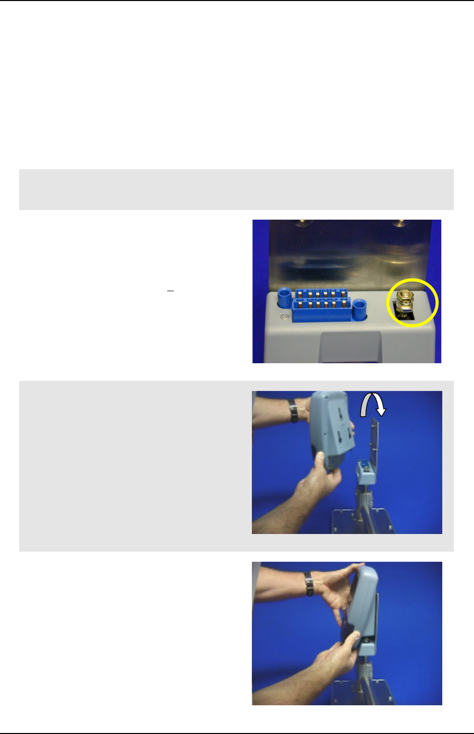
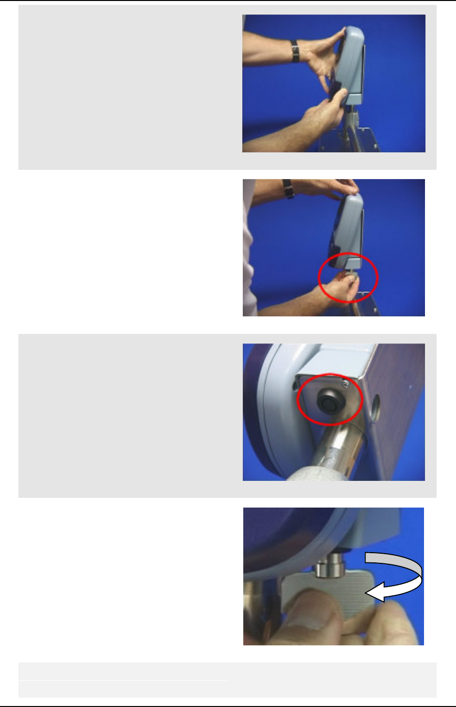
The CID1B is mounted on a cradle secured by a locking device. The following diagrams
detail the components of the CID1B.
1. Turn off the CID1B.
2. Ensure the keybolt on the cradle is
pointing forward to fit the Keybolt
Opening.
Note: The correct height of the locking
bolt is 17/64” (6.7mm + 0.1). This
should be checked prior to installation.
3. Align the CID1B slots with the
Mounting Bolts on the front of the
Cradle.
4. Check the CID1B is aligned with the
Cradle Serial Contacts.
Device Product Group Security Level 3 CID1B Field Maintenance Manual
DPG-00253 ERG Confidential © ERG 2003 Page 17 of 21
Revision 1 / 13 Nov 03
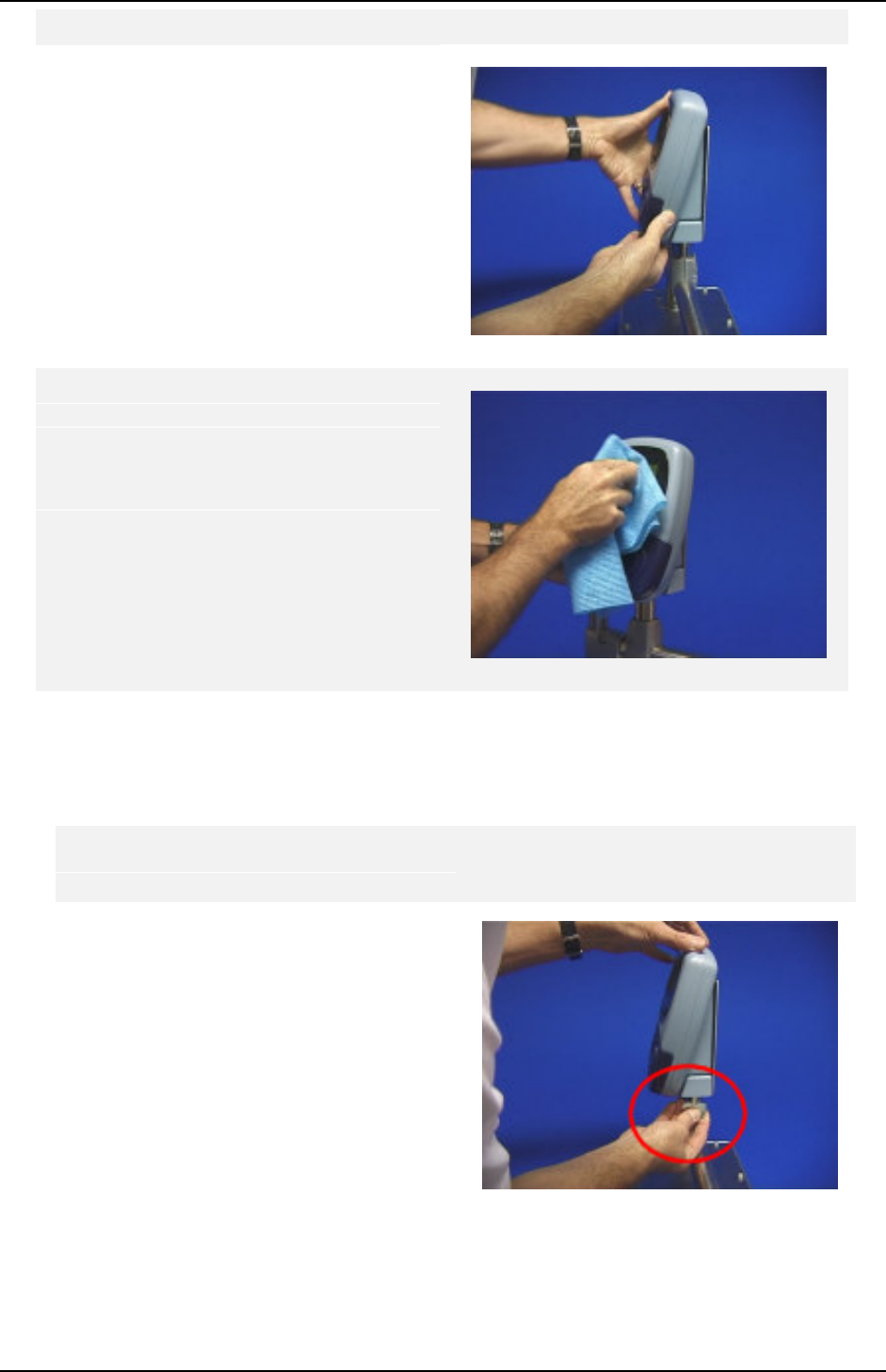
5. Seat the unit by pushing back and
down until it clicks in place.
The Keybolt on the cradle will now be
fully enclosed by the CID1B. Place the
Device Action Lock Key into the key
entry point.
Key Entry Point.
6. Turn the key firmly in a clockwise
direction. The CID1B is now securely
on the cradle.
7. Power up the On-Board equipment
and check the operation of the LCD
Device Product Group Security Level 3 CID1B Field Maintenance Manual
DPG-00253 ERG Confidential © ERG 2003 Page 18 of 21
Revision 1 / 13 Nov 03
display, LEDs and loudspeaker.
8. Check the CID1B is positioned
correctly to allow the patron to see the
PID clearly.
9. Remove any dirt or dust from the
surface of the equipment with a damp
cloth.
Note: Prolonged use of concentrated
cleaning solvents will lead to
permanent damage to the outer casing.
7.2 Removal of CID1B
This section describes the method of removal for the CID1B.
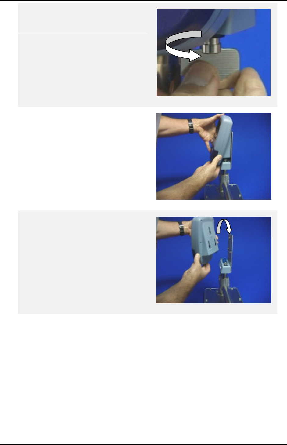
1. Turn off the CID1B
2. Locate the Device Action Lock Key
Keybolt on the CID1B.
Device Product Group Security Level 3 CID1B Field Maintenance Manual
DPG-00253 ERG Confidential © ERG 2003 Page 19 of 21
Revision 1 / 13 Nov 03
3. Turn the key firmly in an anti-
clockwise direction until the CID1B
is released from the cradle.
4. Gently lift the casing directly upwards
until it disengages with a click from
the cradle.
5. Unhook the CID1B from the
Mounting Bolts on the front of the
Cradle
6. Pack the CID1B into the packaging
from the replacement CID1B.

Device Product Group Security Level 3 CID1B Field Maintenance Manual
DPG-00253 ERG Confidential © ERG 2003 Page 20 of 21
Revision 1 / 13 Nov 03
8 CID1B Audio/Visual Indicators
The CID1B has audible and visual indicators to speed up patron throughput.
These indicators inform both the driver and patron of the status of the current smart card
transaction. This reduces the need for the patron to read the LCD and thus increases
patron throughput. For example, viewing a green LED and hearing a valid audible tone
from the loudspeaker is faster than reading "VALID TRANSACTION".
The typical values for the various tones and LED displays, along with the PID display, are
shown below in Table 3.
The CID1B audio indicators are three types of tones:
Valid transaction – a single tone of 1000Hz for 200ms.
Invalid transaction – three tones of 1400Hz for 100ms with a 50ms delay
between tones .
Low value transaction – two tones, first tone 1000Hz for 200ms, and second
tone 1200Hz for 200ms with a 50ms delay between
tones.
The CID1B visual indicators are red, green and amber LEDs:
Red – represents invalid transactions, (Out Of Service) or closed, all LEDs will
be on.
Green – a represents valid transactions.
Amber – a warning to the patron that e.g. funds have automatically been added
through the auto load facility. Travel is allowed for this transaction and therefore
the green LED is also on.
Table 3: Audio/Visual Indicators Typical Values
Transaction Screen Display LED
Display
Freq.
(Hz)
Duration
(ms) Pause Sequence
Valid card
used, $0.70
fare deducted
TRAVEL OK
FARE $0.70
BAL $25.30
Green 1000 200 None One Single
Tone
Valid card
One ride used
TRAVEL OK
RIDE USED
BAL 8 RIDES
Green 1000 200 None One Single
Tone
Valid card
upgrade UPGRADE OK
FARE $0.00
BAL $35.00
Green 1000 200 None One Single
Tone
Valid Senior TRAVEL OK
FAST PASS
RENEWED
OK TO FEB 28
Green 1000 200 None One Single
Tone
Low Value TRAVEL OK
FARE $0.70
BALANCE $0.70
Green
Amber
1000
then
1200
200 50 Two
Ascending
Tones
Low Funds TRAVEL DENIED
LOW FUNDS
BALANCE: $0.XX
Red 1400 100 50 Three Single
Tones
Device Product Group Security Level 3 CID1B Field Maintenance Manual
DPG-00253 ERG Confidential © ERG 2003 Page 21 of 21
Revision 1 / 13 Nov 03
Transaction Screen Display LED
Display
Freq.
(Hz)
Duration
(ms) Pause Sequence
Invalid TRAVEL DENIED
CARD INVALID
Red 1400 100 50 Three Single
Tones
Passback TRAVEL DENIED
CARD ALREADY
PROCESSED
Red 1400 100 50 Three Single
Tones
Expired TRAVEL DENIED
CARD EXPIRED
Red 1400 100 50 Three Single
Tones
Not Permitted TRAVEL NOT
PERMITTED Red 1400 100 50 Three Single
Tones
Hotlisted TRAVEL DENIED
CARD BLOCKED
Red 1400 100 50 Three Single
Tones
Table 4: LED Functionality
Function Red Amber Green
OUT OF SERVICE
(Equipment Fault, not processing
smart cards – end of day, etc.) ON ON ON
IDLE -------- ----- -----
LAST TRANSACTION -------- ON ------
Valid card or transaction ON ------ ------
Invalid card or transaction ------ ------ ON