ERG Transit Systems MCR500 PC TYPE CARD READER User Manual users manual
ERG Transit Systems PC TYPE CARD READER users manual
Contents
- 1. USER MANUAL
- 2. users manual
users manual

FCC ID: Q47-MCR500 EMC Technologies Report No. T50307_A Page 1 of 13
EMC Technologies Pty Ltd
Unit 3/87 Station Road,
Seven Hills, NSW 2147 Australia
+612 9624 2777 +612 9838 4050 www.emctech.com.au
APPENDIX G
USER MANUAL
This material is confidential to ERG and may not be disclosed in whole or in part to any third party nor used in any
manner whatsoever other than for the purposes expressly consented to by ERG in writing.
This material is also copyright and may not be reproduced, stored in a retrieval system or transmitted in any form or
by any means in whole or in part without the express written consent of ERG.
Device Product Group
MCR500 User Manual
Document No: DPG-00266 Category: 81 Revision: 2
ERG
Approvals Author Manager Group Manager
Name: Dan Zorde Stefan Walter Gino Bertino
Signature:
Date:

Device Product Group Security Level 3 MCR500 User Manual
DPG-00266 ERG Confidential © ERG 2005 Page 2 of 12
Revision 2 / 4 Mar 2005
Document History
Revision Revision
Date Description Author
0.1 12 Jan 2004 Initial Draft M Hanssen
1.0 8 Mar 2004 Released M Hanssen
1.1 28 Feb 2005 Updated with details of short variant MCR500 Dan Zorde
2.0 4 Mar 2005 Released for FCC Dan Zorde

Device Product Group Security Level 3 MCR500 User Manual
DPG-00266 ERG Confidential © ERG 2005 Page 3 of 12
Revision 2 / 4 Mar 2005
Table of Contents
1 INTRODUCTION .................................................................................................................................. 6
1.1 PURPOSE........................................................................................................................................ 6
1.2 SCOPE............................................................................................................................................ 6
1.3 TERMINOLOGY ................................................................................................................................6
2 MCR500 TECHNICAL SPECIFICATIONS........................................................................................... 7
3 ELECTRICAL SPECIFICATION .......................................................................................................... 8
3.1 HOST PCMCIA INTERFACE ............................................................................................................. 8
3.2 POWER SUPPLY .............................................................................................................................. 8
3.3 RF CONTROLLER............................................................................................................................. 8
3.3.1 Transmitter............................................................................................................................ 8
3.3.2 Receiver................................................................................................................................ 8
4 RECOMMENDED HARDWARE .......................................................................................................... 9
5 SOFTWARE AND IPAQ CONFIGURATION .....................................................................................10
5.1 TEST SOFTWARE........................................................................................................................... 10
5.2 IPAQ SOFTWARE INSTALLATION .................................................................................................... 10
6 MCR500.............................................................................................................................................. 11
6.1 MCR500 PHOTO’S....................................................................................................................... 11
6.2 MCR500 SHORT VARIANT PHOTO’S.............................................................................................. 12

Device Product Group Security Level 3 MCR500 User Manual
DPG-00266 ERG Confidential © ERG 2005 Page 4 of 12
Revision 2 / 4 Mar 2005
List of Tables
TABLE 1: RECOMMENDED HARDWARE.............................................................................................................. 9
List of Figures
FIGURE 1: TERMINOLOGY ................................................................................................................................6
FIGURE 2: IPAQ WITH MCR500 AND MCR500 SHORT VARIANT PHOTOS......................................................... 9
FIGURE 3: SOFTWARE ................................................................................................................................... 10
FIGURE 4: MCR500 PHOTO OF THE FRONT ................................................................................................... 11
FIGURE 5: MCR500 PHOTO OF THE BACK ..................................................................................................... 11
FIGURE 6: MCR500 SHORT VARIANT PHOTO OF THE FRONT.......................................................................... 12
FIGURE 7: MCR500 SHORT VARIANT PHOTO OF THE BACK............................................................................ 12

Device Product Group Security Level 3 MCR500 User Manual
DPG-00266 ERG Confidential © ERG 2005 Page 5 of 12
Revision 2 / 4 Mar 2005
FCC Compliance Statement
This device complies with Part 15 of the FCC rules. Operation is subject to the following
two conditions: (1) This device may not cause harmful interference, and (2) this device
must accept any interference received, including interference that may cause undesired
operation.
This equipment has been tested and found to comply with the limits for a Class B digital
device, pursuant to Part 15 of the FCC Rules. These limits are designed to provide
reasonable protection against harmful interference in a residential installation. This
equipment generates, uses and can radiate radio frequency energy and, if not installed
and used in accordance with the instructions, may cause harmful interference to radio
communications. However, there is no guarantee that interference will not occur in a
particular installation. If this equipment does cause harmful interference to radio or
television reception, which can be determined by turning the equipment off and on, the
user is encourage to try to correct the interference by one or more of the following
measures:
• Reorient or relocate the receiving antenna.
• Increase the separation between the equipment and receiver.
• Connect the equipment into an outlet on a circuit different from that to which the
receiver is connected.
• Consult the dealer or an experienced radio/TV technician for help.
Warning: Any changes or modifications not expressively approved by ERG Transit
Systems could void the user's authority to operate this equipment

Device Product Group Security Level 3 MCR500 User Manual
DPG-00266 ERG Confidential © ERG 2005 Page 6 of 12
Revision 2 / 4 Mar 2005
1 Introduction
1.1 Purpose
The purpose of this document is to provide summary technical details of the electrical
interface and physical characteristic of the Multiprotocol Card Reader (MCR500) and its
shorter variant. It is intended for use by third party developers wanting to integrate the
MCR500 Module into new or existing products.
1.2 Scope
This manual is intended for use by third party developers and integrators familiar with
similar type of equipment. This manual contains technical information sufficient to give
technical personnel an operational understanding of the MCR500 and its variant.
1.3 Terminology
Figure 1: Terminology
Term Definition
A Amp(s), Ampere(s)
ASK Amplitude Shift Keying
bps Bits per second
BPSK Binary Phased Shift Keying
CMOS Complementary Metal-Oxide Semiconductor
CSC Contact-less Smart Card
DUT Device Under Test
EEPROM Electrically Eraseable ROM
EMC Electromagnetic Compatibility
EPLD Eraseable, Programmable Logic Device
GND Ground – negative supply
Host A processing unit. (iPaq)
Hz Hertz, cycles per second
IEC International Electrotechnical Commission
ISO International Standards Organisation
JTAG Joint Test Action Group
MCR Multi protocol Contactless Reader
mm millimetre(s)
NRZ-L Non-return to zero - level
OOK On-Off keying
PCB Printed Circuit Board
RAM Random Access Memory
s second(s)
SAM Security Access Module

Device Product Group Security Level 3 MCR500 User Manual
DPG-00266 ERG Confidential © ERG 2005 Page 7 of 12
Revision 2 / 4 Mar 2005
2 MCR500 Technical Specifications
Form Factor
• PCMCIA Type II PC Card Extended.
• Card and Socket Services 2.1 compliant
Contactless Card
• Contact less cards as per ISO 14443 type A & type B
• 8bit Parallel access to controller.
Security Access Modules
• 2 x ID-000 SAM sockets provided.
• 8Bit Parallel access to controller.
Power Consumption
• <500mA worst case. (Datasheet Calculations, 5V SAMs)
• <160mA @ 3.3V (Card transaction with 2 SAMs)
• <50mA when in standby mode (Both chips in standby mode).
• <15mA when in sleep mode
Temperature Range
• Operating temperature range 0º to +70ºC.
• Storage temperature range -20º to +80ºC.
Weight & Dimmensions
• 40g
• 121.6 x 53.9 x 5.0mm (± 0.3)
Humidity
• 5% to 95% Relative Humidity (non- condensing).
Ingress Protection
• IP52.
EMC Compliance
• US – FCC Part 15
• Europe - CE R&TTE
• Australia C Tick
Operating System
• Windows CE 2003 (Driver available)
• Extendable to other PC operating systems.

Device Product Group Security Level 3 MCR500 User Manual
DPG-00266 ERG Confidential © ERG 2005 Page 8 of 12
Revision 2 / 4 Mar 2005
3 Electrical specification
3.1 Host PCMCIA interface
Item Description
MCR to Host
communication interface PCMCIA Type II PC Card Extended.
Card and Socket Services 2.1 compliant
3.2 Power Supply
The MCR500 PC Card module derives power directly from the host.
Item Description
Supply voltage 3.3Vdc ±0.1V with ripple of less than 100mV peak-peak.
Supply current Maximum 500 mA, typical 150 mA
Input power
requirements Maximum 1.65 Watts, typical 0.5 Watts
3.3 RF controller
The standards supported by the RF controller are ISO/IEC 14443 Type A, ISO/IEC 14443
Type B and Mifare Standard.
3.3.1 Transmitter
The MCR500 transmitter complies with the following specifications:
Item Description
Carrier Frequency 13.56 MHz + 7 kHz (ISO/IEC 14443-2:2001, 6.1)
Modulation Rise and
Fall Time < 2.0 µsec (ISO/IEC 14443-2:2001, 8.1.2 and 9.1.2)
ASK Modulation 100% Modified Miller (ISO/IEC 14443-2:2001, 7 and 8)
8%-14% NRZ (ISO/IEC 14443-2:2001, 7 and 9)
3.3.2 Receiver
The MCR500 receiver complies with the following specifications:
Item Description
Carrier Frequency 13.56 MHz
Subcarrier
Frequency 847.5 kHz (ISO/IEC 14443-2:2001, 7, 8 and 9)
Subcarrier Data OOK Manchester (ISO/IEC 14443-3:2001 7 and 8)
BPSK NRZ-L (ISO/IEC 14443-2:2001, 7 and 9)
Device Product Group Security Level 3 MCR500 User Manual
DPG-00266 ERG Confidential © ERG 2005 Page 9 of 12
Revision 2 / 4 Mar 2005
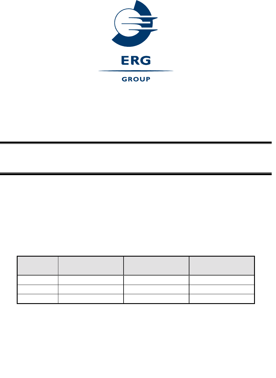
4 Recommended Hardware
Figure 2: iPAQ with MCR500 and MCR500 Short Variant Photos
Ref Item /
Order No Description Qty Source /
Manufacturer Purpose
1. H5550/
FA107A
IPAQ Pocket PC
H5550
1 Hewlett-Packard Processing Unit, Interface
for transactions
2. 249704-B22
FA120A#AC3
PC Card
Expansion Pack 1 Hewlett-Packard PC Slot for IPAQ, external
battery
3. MCR500 /
11081 Multipurpose
Card Reader 1 ERG Card reader
4. MCR500 /
18252 Multipurpose
Card Reader 1 ERG Card reader with shorter
antenna
Table 1: Recommended Hardware

Device Product Group Security Level 3 MCR500 User Manual
DPG-00266 ERG Confidential © ERG 2005 Page 10 of 12
Revision 2 / 4 Mar 2005
5 Software and iPAQ Configuration
The following describes how the iPAQ software should be configured for correct
operation. This assumes that an application based on ERG example source files has
been created called MCR500APP.EXE.
5.1 Test Software
Ref Description Ver Source Purpose
1. MCR500.DLL 1.0.0.6 ERG MCR500 PCMCIA Driver
2. MCR500APP.EXE 1.0 ERG MCR500 Application Software
3. MFCCE300D.DLL 6.0.99.0 MS MFC DLL
4. CIS.BIN 00.15 ERG MCR500 EEPROM Code (CIS)
Figure 3: Software
5.2 iPAQ Software installation
Install Microsoft ActiveSync on the PC following the instructions which came with the
iPAQ. After successful installation place the iPAQ into its cradle and wait for ActiveSync
to connect. Then launch the ActiveSync Explorer from the PC’s System Tray and copy
the following files from the DAMS release floppy onto the iPAQ:
A:\mcr500.dll to \Windows
A:\ mfcce300d.dll to \Windows
A:\mcr500app.exe to \Windows\Start Menu
A:\cis.bin to \
Enable mcr500app in the Start Menu by selecting the appropriate entry in:
Start|Settings|Menus
Device Product Group Security Level 3 MCR500 User Manual
DPG-00266 ERG Confidential © ERG 2005 Page 11 of 12
Revision 2 / 4 Mar 2005
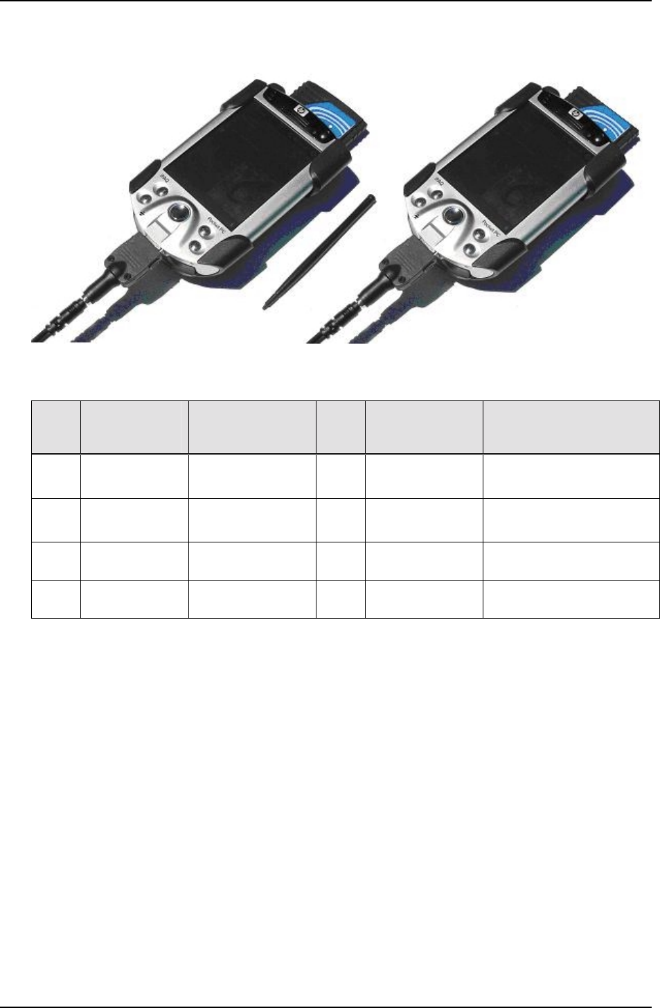
6 MCR500
6.1 MCR500 Photo’s
Figure 4: MCR500 Photo of the Front
Figure 5: MCR500 Photo of the Back
Device Product Group Security Level 3 MCR500 User Manual
DPG-00266 ERG Confidential © ERG 2005 Page 12 of 12
Revision 2 / 4 Mar 2005
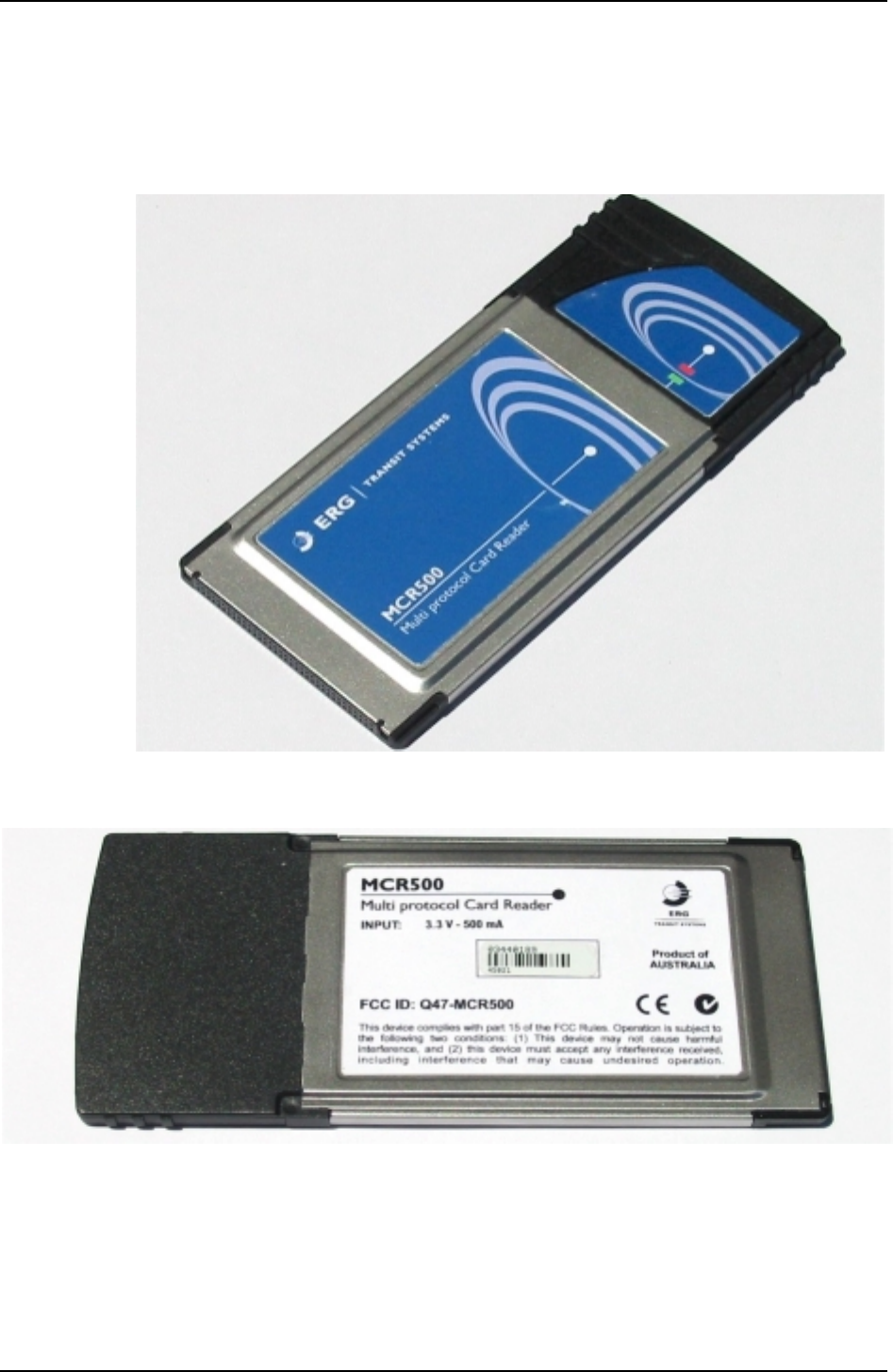
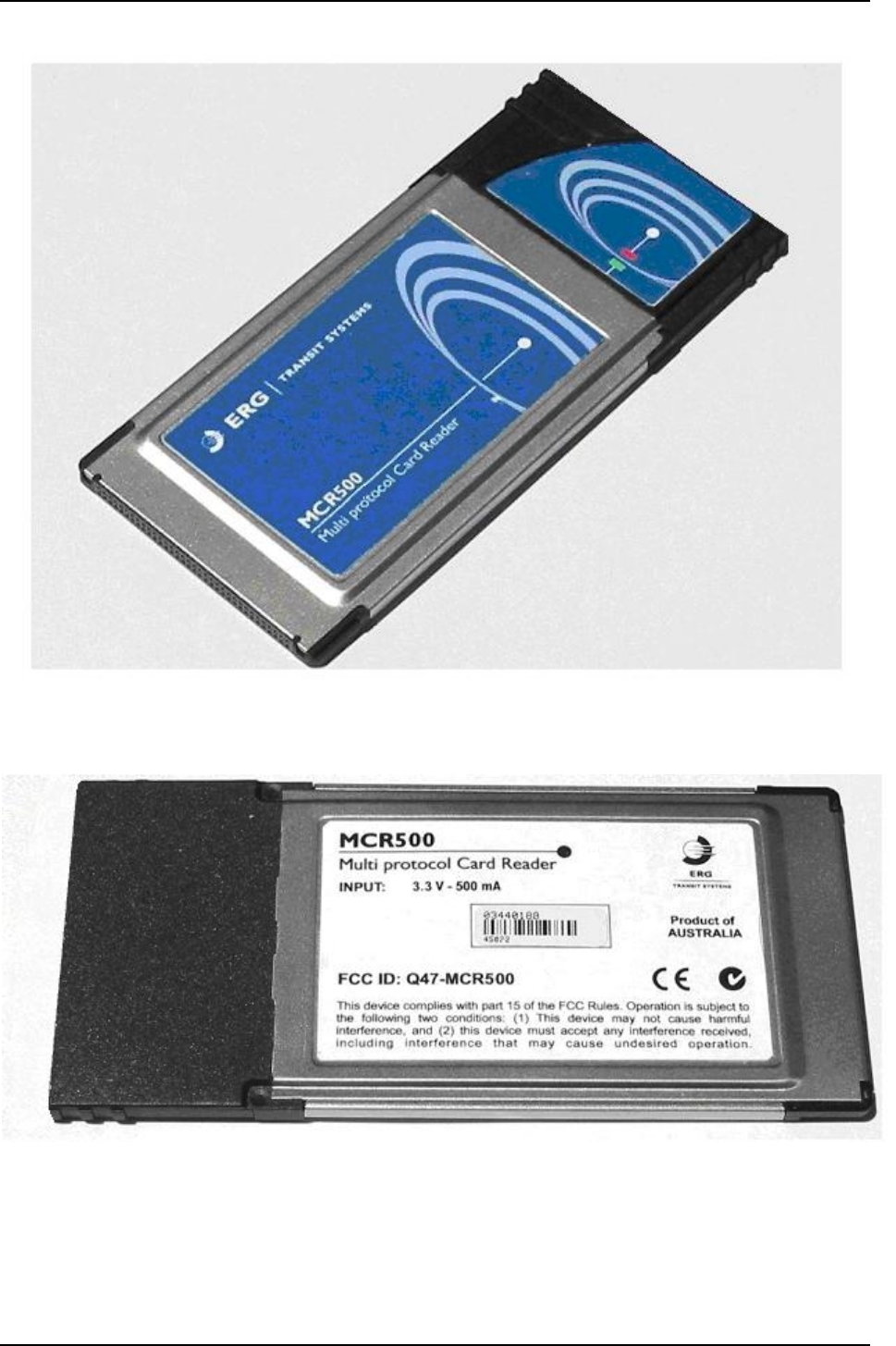
6.2 MCR500 Short Variant Photo’s
Figure 6: MCR500 Short Variant Photo of the Front
Figure 7: MCR500 Short Variant Photo of the Back